EP3930062A1 - Method for fabricating electrode assembly of secondary battery and device - Google Patents
Method for fabricating electrode assembly of secondary battery and device Download PDFInfo
- Publication number
- EP3930062A1 EP3930062A1 EP20874982.0A EP20874982A EP3930062A1 EP 3930062 A1 EP3930062 A1 EP 3930062A1 EP 20874982 A EP20874982 A EP 20874982A EP 3930062 A1 EP3930062 A1 EP 3930062A1
- Authority
- EP
- European Patent Office
- Prior art keywords
- separator
- electrode plate
- negative electrode
- positive electrode
- joining
- Prior art date
- Legal status (The legal status is an assumption and is not a legal conclusion. Google has not performed a legal analysis and makes no representation as to the accuracy of the status listed.)
- Granted
Links
Images


Classifications
-
- H—ELECTRICITY
- H01—ELECTRIC ELEMENTS
- H01M—PROCESSES OR MEANS, e.g. BATTERIES, FOR THE DIRECT CONVERSION OF CHEMICAL ENERGY INTO ELECTRICAL ENERGY
- H01M10/00—Secondary cells; Manufacture thereof
- H01M10/04—Construction or manufacture in general
- H01M10/0431—Cells with wound or folded electrodes
-
- H—ELECTRICITY
- H01—ELECTRIC ELEMENTS
- H01M—PROCESSES OR MEANS, e.g. BATTERIES, FOR THE DIRECT CONVERSION OF CHEMICAL ENERGY INTO ELECTRICAL ENERGY
- H01M10/00—Secondary cells; Manufacture thereof
- H01M10/04—Construction or manufacture in general
- H01M10/0404—Machines for assembling batteries
- H01M10/0409—Machines for assembling batteries for cells with wound electrodes
-
- H—ELECTRICITY
- H01—ELECTRIC ELEMENTS
- H01M—PROCESSES OR MEANS, e.g. BATTERIES, FOR THE DIRECT CONVERSION OF CHEMICAL ENERGY INTO ELECTRICAL ENERGY
- H01M10/00—Secondary cells; Manufacture thereof
- H01M10/04—Construction or manufacture in general
- H01M10/0468—Compression means for stacks of electrodes and separators
-
- H—ELECTRICITY
- H01—ELECTRIC ELEMENTS
- H01M—PROCESSES OR MEANS, e.g. BATTERIES, FOR THE DIRECT CONVERSION OF CHEMICAL ENERGY INTO ELECTRICAL ENERGY
- H01M50/00—Constructional details or processes of manufacture of the non-active parts of electrochemical cells other than fuel cells, e.g. hybrid cells
- H01M50/10—Primary casings; Jackets or wrappings
- H01M50/102—Primary casings; Jackets or wrappings characterised by their shape or physical structure
- H01M50/103—Primary casings; Jackets or wrappings characterised by their shape or physical structure prismatic or rectangular
-
- Y—GENERAL TAGGING OF NEW TECHNOLOGICAL DEVELOPMENTS; GENERAL TAGGING OF CROSS-SECTIONAL TECHNOLOGIES SPANNING OVER SEVERAL SECTIONS OF THE IPC; TECHNICAL SUBJECTS COVERED BY FORMER USPC CROSS-REFERENCE ART COLLECTIONS [XRACs] AND DIGESTS
- Y02—TECHNOLOGIES OR APPLICATIONS FOR MITIGATION OR ADAPTATION AGAINST CLIMATE CHANGE
- Y02E—REDUCTION OF GREENHOUSE GAS [GHG] EMISSIONS, RELATED TO ENERGY GENERATION, TRANSMISSION OR DISTRIBUTION
- Y02E60/00—Enabling technologies; Technologies with a potential or indirect contribution to GHG emissions mitigation
- Y02E60/10—Energy storage using batteries
-
- Y—GENERAL TAGGING OF NEW TECHNOLOGICAL DEVELOPMENTS; GENERAL TAGGING OF CROSS-SECTIONAL TECHNOLOGIES SPANNING OVER SEVERAL SECTIONS OF THE IPC; TECHNICAL SUBJECTS COVERED BY FORMER USPC CROSS-REFERENCE ART COLLECTIONS [XRACs] AND DIGESTS
- Y02—TECHNOLOGIES OR APPLICATIONS FOR MITIGATION OR ADAPTATION AGAINST CLIMATE CHANGE
- Y02P—CLIMATE CHANGE MITIGATION TECHNOLOGIES IN THE PRODUCTION OR PROCESSING OF GOODS
- Y02P70/00—Climate change mitigation technologies in the production process for final industrial or consumer products
- Y02P70/50—Manufacturing or production processes characterised by the final manufactured product
Definitions
- the present application relates to the field of battery technology, in particular to a method and apparatus for manufacturing an electrode assembly of a secondary battery.
- the main source of power for new energy vehicles is power batteries.
- the electrode assembly forming the power battery is wound by a winding machine, making the winding machine become an important apparatus for the production of power batteries.
- the currently equipped winding machine basically adopts a process in which the positive electrode plate, the separator, the negative electrode plate, and the separator are simultaneously wound around the winding needle and then cut. This type of winding machine is prone to problems such as the folding of the pole piece and the entraining of dust in winding during the production process, which in turn affects the yield and production efficiency of the electrode assembly.
- the current winding manner requires a roll-in auxiliary mechanism, such as a merging film roller group or a rolling feeding component, to be disposed in the upstream close to the winding needle to assist the positive electrode plate, the separator and the negative electrode plate to smoothly enter the winding needle separately, which causes the structure of the winding machine is complicated, and the efficiency of feeding and winding is low.
- a roll-in auxiliary mechanism such as a merging film roller group or a rolling feeding component
- Embodiments of the present application provide a method and apparatus for manufacturing an electrode assembly of a secondary battery.
- the method for manufacturing the electrode assembly of the secondary battery can improve the yield of the electrode assembly, simplify the structure of the winding apparatus, and improve the efficiency of the winding operation.
- Embodiments of the present application proposes a method for manufacturing an electrode assembly of a secondary battery, which includes:
- a cutting off process is performed for the positive electrode plate in the upstream of the joining position of the positive electrode plate and the first separator;
- a cutting off process is performed for the negative electrode plate in the upstream of the joining position of the negative electrode plate and the second separator.
- a dust removal process is performed for the positive electrode plate and/or the first separator before joined;
- a dust removal process is performed for the negative electrode plate and/or the second separator before joined.
- the composite starting end and/or the composite ending end of the positive electrode plate is adhesively connected to the first separator;
- the composite starting end and/or the composite ending end of the negative electrode plate is adhesively connected to the second separator.
- the positive electrode composite plate body and the negative electrode composite plate body together to form an electrode assembly in the step of winding the positive electrode composite plate body and the negative electrode composite plate body together to form an electrode assembly, the positive electrode composite plate body and/or the negative electrode composite plate body is transported from bottom to top to winding station and a winding process is performed.
- the joining of the positive electrode plate and the first separator may be completed in composite manner such as electrostatic adsorption, hot pressing joining, or glue pasting joining; and/or the joining of the negative electrode plate and the second separator may be completed in a composite manner such as electrostatically adsorption, plasma adsorption, hot pressing joining or glue pasting joining.
- the positive electrode plate and the first separator are joined in advance, and the negative electrode plate and the second separator are joined, so that the positive electrode plate and the first separator are connected to each other to form a whole, and the negative electrode plate and the second separator are connected to each other to form a whole.
- the positive electrode composite plate body and the negative electrode composite plate body are separately transported to the winding station.
- the positive electrode plate and the negative electrode plate are separately driven by the first separator and the second separator to enter the winding process.
- the method for manufacturing the electrode assembly of the secondary battery in the embodiments of the present application can effectively reduce the total number of plate bodies entering the winding process. Therefore it is beneficial to reducing the difficulty of aligning the positive electrode plate, the negative electrode plate and the separator, reducing the possibility that the positive electrode plate and the negative electrode plate are not aligned with each other, and improving the winding alignment accuracy.
- alignment means that the positive electrode plate, the negative electrode plate and the separator are aligned with each other in their respective width directions.
- the positive electrode plate, the negative electrode plate and the separator may not be provided with a roll-in auxiliary mechanism, such as a merging film roller group or a rolling feeding component, for guiding the positive electrode plate and the negative electrode plate to be rolled in, in the upstream close to the winding station, which is beneficial to reducing the number of parts used, simplifying the overall structure of the corresponding winding apparatus, and at the same time improving the efficiency of the winding operation.
- a roll-in auxiliary mechanism such as a merging film roller group or a rolling feeding component
- Embodiments of the present application further provide an apparatus for manufacturing an electrode assembly of a secondary battery, which includes:
- the apparatus further includes a positive electrode plate cutter, the positive electrode plate cutter is arranged in the upstream of the first joining device, and the positive electrode plate cutter is configured for cutting off the positive electrode plate in the upstream the joining position of the positive electrode plate and the first separator; and/or
- the apparatus further includes a negative electrode plate cutter, the negative electrode plate cutter is arranged in the upstream of the second joining device, and the negative electrode plate cutter is configured for cutting off the negative electrode plate in the upstream of the joining position of the negative electrode plate and the second separator.
- the apparatus further includes a first dust removal device, the first dust removal device is arranged in the upstream of the first joining device, and the first dust removal device is configured for performing dust removal process for the positive electrode plate and/or the first separator before joined; and/or
- the apparatus further includes a second dust removal device, the second dust removal device is arranged in the upstream of the second joining device, and the second dust removal device is configured for performing a dust removal process for the negative electrode plate and/or the second separator before joined.
- the winding device includes a winding needle, a positive electrode roll-in guide roller group and a negative electrode roll-in guide roller group, and the positive electrode roll-in guide roller group and the negative electrode roll-in guide roller group are both arranged in the upstream of the winding needle, the positive electrode roll-in guide roller group and the negative winding roller group are disposed below the winding needle, the positive electrode roll-in guide roller group transports the positive electrode composite plate body directly to the winding needle from bottom to top, and the negative electrode roll-in guide roller group transports the negative composite plate body directly to the winding needle from bottom to top.
- the winding device further includes a rotating base and two or more winding needles, and the two or more winding needles are arranged on the rotating base at intervals around a rotation axis of the rotating base.
- the apparatus further includes a first glue pasting device, the first glue pasting device is arranged in the downstream of the first joining device, and the first glue pasting device is configured for adhesively connecting the composite starting end and/or the composite ending end of the positive electrode plate to the first separator; and/or
- the apparatus further includes a second glue pasting device, the second glue pasting device is arranged in the downstream of the second joining device, and the second glue pasting device is configured for adhesively connecting the composite starting end and/or composite ending end of the negative electrode plate to the second separator.
- the apparatus further includes a first detection device, the first detection device is arranged in the downstream of the first joining device, and the first detection device is configured for detecting the composite alignment degree of the positive electrode plate and the first separator; and/or
- the apparatus further includes a second detection device, the second detection device is provided in the downstream of the second joining device, the second detection device is configured for detecting the composite alignment degree of the negative electrode plate and the second separator.
- the apparatus further includes a first correcting device, the first correcting device is arranged in the upstream of the first joining device, the first correcting device is configured for adjusting the relative position of the positive electrode plate and the first separator; and/or
- the apparatus further includes a second correcting device, the second correcting device is arranged in the upstream of the second joining device, the second correcting device is configured for adjusting the relative position of the negative electrode plate and the second separator.
- the apparatus further includes a tension adjusting device, the tension adjusting device is arranged in the upstream of the winding device, and is configured for adjusting the tension of the positive electrode composite plate body or the negative electrode composite plate body.
- the positive electrode plate and the first separator are joined in advance by the first joining device, and the negative electrode plate and the second separator are joined in advance by the second joining device, so that the positive electrode plate and the first separator are connected to each other to form a whole, and the negative electrode plate and the second separator are connected to each other to form a whole.
- the positive electrode composite plate body and the negative electrode composite plate body are separately transported to the winding station of the winding device to complete the winding operation.
- the positive electrode plate and the negative electrode plate are respectively driven by the first separator and the second separator to enter the winding process.
- the apparatus for manufacturing the electrode assembly of the secondary battery in the embodiment of the present application can effectively reduce the total number of plate bodies entering the winding process, which is beneficial to reducing the difficulty of aligning the positive electrode plate, the negative electrode plate and the separator, reducing the possibility that the positive electrode plate and the negative electrode plate are not aligned with each other, and improving the winding alignment accuracy.
- the positive electrode plate, the negative electrode plate and the separator may not be provided with a roll-in auxiliary mechanism for guiding the positive electrode plate and the negative electrode plate to be rolled in in the upstream close to the winding device, which is beneficial to reducing the number of parts used, simplifying the overall structure of the apparatus, and at the same time improving the efficiency of winding operation.
- first dust removal device 112, second dust removal device; 113. separator cutter; 114. first glue pasting device; 115. second glue pasting device; 116. first detection device; 117. second detection device; 118. first correction device; 119. second correction device.
- the secondary battery 10 includes a case 11, an electrode assembly 12 provided in the case 11, and a top cover assembly that is hermetically connected to the case 11.
- the case 11 in the embodiment of the present application has a square structure or other shapes.
- the case 11 has an internal space for accommodating the electrode assembly 12 and the electrolyte, and an opening communicating with the internal space.
- the case 11 may be made of materials such as aluminum, aluminum alloy, or plastic.
- the electrode assembly 12 of the embodiment of the present application includes a positive electrode plate 121, a negative electrode plate 123 and a separator, wherein the separator is an insulator between the positive electrode plate 121 and the negative electrode plate 123.
- the electrode assembly 12 has a main body and tabs.
- the main body of the present embodiment has a flat structure as a whole, which has a predetermined thickness, height, and width.
- the active material of the positive electrode plate 121 is coated on the coated area of the positive electrode plate 121, and the active material of the negative electrode plate 123 is coated on the coated area of the negative electrode plate 123.
- the uncoated area extending from the coated area of the main body is used as a tab.
- the electrode assembly 12 includes two tabs, namely a positive electrode tab and a negative electrode tab.
- the positive electrode tab extends from the coated area of the positive electrode plate 121, and the negative electrode tab extends from the coated area of the negative electrode plate 123.
- embodiments of the present application provide a method for manufacturing an electrode assembly 12 of a secondary battery 10, which includes the following steps:
- the positive electrode plate 121 and the first separator 122 may complete the joining in a composite manner such as electrostatic adsorption, hot pressing joining or glue pasting joining.
- the positive electrode plate 121 and the first separator 122 are laminated on each other along the thickness direction of the positive electrode plate 121.
- the negative electrode plate 123 and the second separator 124 can complete the joining in a composite manner such as electrostatic adsorption, plasma adsorption, hot pressing joining or glue pasting joining.
- the negative electrode plate 123 and the second separator 124 are laminated on each other in the thickness direction of the negative electrode plate 123.
- the positive electrode plate 121 and the first separator 122 are joined in advance, and the negative electrode plate 123 and the second separator 124 are joined, so that the positive electrode plate 121 and the first separator 122 are connected to each other to form a whole, and the negative electrode plate 123 and the second separator 124 are connected to each other to form a whole.
- the positive electrode composite plate body 20 and the negative electrode composite plate body 30 are separately transported to the winding station.
- the positive electrode plate 121 and the negative electrode plate 123 are respectively driven by the first separator 122 and the second separator 124 to enter the winding process.
- the method for manufacturing the electrode assembly 12 of the secondary battery 10 can effectively reduce the total number of plate body entering into the winding process.
- alignment means that the positive electrode plate 121, the negative electrode plate 123, and the separator are aligned with each other in their respective width directions.
- the positive electrode plate 121 and the negative electrode plate 123 may be folded or wrinkled when entering into the winding process, which effective improves the yield of the electrode assembly 12; moreover, the positive electrode plate 121, the negative electrode plate 123 and the separator may not be provided with a roll-in auxiliary mechanism, such as a merging film roller group or a rolling feeding component, for guiding the positive electrode plate 121 and the negative electrode plate 123 to be rolled in in the upstream close to the winding station, which is beneficial to reducing the number of parts used, simplifying the overall structure of the corresponding winding apparatus, and at the same time improving the efficiency of winding operation.
- a roll-in auxiliary mechanism such as a merging film roller group or a rolling feeding component
- a cutting off process is performed for the positive electrode plate 121 in the upstream of the joining position of the positive electrode plate 121 and the first separator 122.
- the joining position 99 of the positive electrode plate 121 and the first separator 122 is far away from the winding station. Therefore, the cutting off process is performed for the positive electrode plate 121 in the upstream of the joining position 99, which can further effectively reduce the possibility of a short circuit between the positive electrode plate 121 and the negative electrode plate 123 caused by the dust piercing the separator due to the dust generated during the cutting off process to be rolled in.
- the positive electrode plate 121 After the cutting off process is performed for the positive electrode plate 121, the positive electrode plate 121 forms a composite ending end close to the joining position 99 and a composite starting end far away from the joining position 99 and for winding the next electrode assembly 12 on two sides of the cutting off position, respectively.
- the cutting off process may be performed by a mechanical cutter or a laser cutter.
- a cutting off process is performed for the negative electrode plate 123 in the upstream of the joining position 99 of the negative electrode plate 123 and the second separator 124.
- the joining position 99 of the negative electrode plate 123 and the second separator 124 is far away from the winding station. Therefore, the cutting off process is performed for the negative electrode plate 123 in the upstream of the joining position 99, which can further effectively reduce the possibility of a short circuit between the positive electrode plate 121 and the negative electrode plate 123 caused by the dust piercing the separator due to the dust generated during the cutting off process to be rolled in.
- the negative electrode plate 123 After the cutting off process is performed for the negative electrode plate 123, the negative electrode plate 123 forms a composite ending end close to the joining position 99 and a composite starting end far away from the joining position 99 and for winding the next electrode assembly 12 on two sides of the cutting off place, respectively.
- the cutting off process may be performed by a mechanical cutter or a laser cutter.
- a cutting off process is performed for the positive electrode plate 121 in the upstream of the joining position 99 of the positive electrode plate 121 and the first separator 122, and at the same time before the joining of the negative electrode plate 123 and the second separator 124 is completed, a cutting off process is performed for the negative electrode plate 123 in the upstream of the joining position 99 of the negative electrode plate 123 and the second separator 124.
- a dust removal process is performed for the positive electrode plate 121 before joined, so as to remove dust generated during the cutting off process of the positive electrode plate 121 or remove the dust that enters the area of the positive electrode plate 121 close to the joining position 99 from the external environment, and reduce the possibility that the dust will follow the positive electrode plate 121, remain in the positive electrode composite plate body 20 formed after the joining is completed and follow the positive electrode composite plate body 20 to be rolled in.
- the dust removal process is performed for the first separator 122 before joined to remove the dust that enters the area of the first separator 122 close to the joining position 99 from the external environment and reduce the possibility that the dust will follow the first separator 122, remain in the positive electrode composite plate body 20 formed after the joining is completed and follow the positive electrode composite plate body 20 to be rolled in.
- a dust removal process is simultaneously performed for the positive electrode plate 121 and the first separator 122 before joined.
- a dust removal process is performed for the negative electrode plate 123 before joined, so as to remove dust generated during the cutting off process of the negative electrode plate 123 or remove the dust that enters the area of the negative electrode plate 123 close to the joining position 99 from the external environment, and reduce the possibility that the dust will follow the negative electrode plate 123, remain in the negative electrode composite plate body 30 formed after the joining is completed and follow the negative electrode composite plate body 30 to be rolled in.
- a dust removal process is performed for the second separator 124 before joined to remove the dust that enters the area of the second separator 124 close to the joining position 99 from the external environment, and reduce the possibility that the dust will follow the second separator 124, remain in the negative electrode composite plate body 30 formed after the joining is completed and follow the negative electrode composite plate body 30 to be rolled in.
- the dust removal process is simultaneously performed for the negative electrode plate 123 and the second separator 124 before joined.
- the positive electrode plate 121 to be joined has a composite starting end. After the positive electrode plate 121 is cut off after one winding process is completed, a composite ending end and a composite starting end for the next winding process are formed. In the step that the positive electrode plate 121 and the first separator 122 are joined to form the positive electrode composite plate body 20: the composite starting end or the composite ending end of the positive electrode plate 121 is adhesively connected to the first separator 122, thereby effectively reducing the possibility that during the composite process, the conveying process or the winding process, the composite starting end or the composite ending end of the positive electrode plate 121 joined to the first separator 122 may be folded or wrinkled.
- the composite starting end or composite ending end of the positive electrode plate 121 is adhesively connected to the first separator 122 by an adhesive tape.
- the composite starting end and the composite ending end of the positive electrode plate 121 are adhesively connected to the first separator 122.
- the negative electrode plate 123 to be joined has a composite starting end. After the negative electrode plate 123 is cut off after one winding process is completed, a composite ending end and a composite starting end for the next winding process are formed. In the step that the negative electrode plate 123 and the second separator 124 are joined to form the negative electrode composite plate body 30: the composite starting end or the composite ending end of the negative electrode plate 123 is adhesively connected to the second separator 124, thereby effectively reducing the possibility that during the composite process, the conveying process or the winding process, the composite starting end or the composite ending end of the negative electrode plate 123 joined to the second separator 124 may be folded or wrinkled.
- the composite starting end or composite ending end of the negative electrode plate 123 is adhesively connected to the second separator 124 by an adhesive tape.
- the composite starting end and the composite ending end of the negative electrode plate 123 are adhesively connected to the second separator 124.
- the positive electrode composite plate body 20 and the negative electrode composite plate body 30 is transported from bottom to top to the winding station and the winding process is performed.
- “from bottom to top” refers to the vertical direction as the reference direction. Since the positive electrode plate 121 and the negative electrode plate 123 of the embodiment of the present application are joined with the first separator 122 and the second separator 124 respectively, the positive electrode plate 121 and the negative electrode plate 123 follow the first separator 122 and the second separator 124 respectively to go through the winding process directly.
- the positive electrode composite plate body 20 or the negative electrode composite plate body 30 of the embodiment of the present application can adopt the manner of conveying from bottom to top, and meanwhile the composite starting end and the composite ending end of the positive electrode plate 121 or the negative electrode plate 123 will not be put in a hanging down state under its own gravity, which otherwise results in fold or wrinkle.
- it can further make that during the conveying process of the positive electrode composite plate body 20 or the negative electrode composite plate body 30, the dust carried will be separated and fall under the action of its own gravity, thereby reducing the possibility that the dust will follow the positive electrode composite plate body 20 or the negative electrode composite plate body 30 to enter into the electrode assembly 12 resulting from winding and affect the use safety of the electrode assembly 12.
- the positive electrode composite plate body 20 and the negative electrode composite plate body 30 are conveyed from bottom to top to the winding station and the winding process is performed.
- the method for manufacturing the electrode assembly 12 of the secondary battery 10 in the embodiment of the present application adopts the manner that the positive electrode plate 121 and the first separator 122 are joined and the negative electrode plate 123 and the second separator 124 are joined in advance, and then the composite plate body 20 and the negative electrode composite plate body 30 are wound.
- the method in the embodiment of the present application is no longer necessary to provide a roll-in auxiliary mechanism for guiding the positive electrode plate 121, the negative electrode plate 123 and the two separators to be rolled in, thereby reducing the number of parts used, at the same time more easily ensuring the accuracy of alignment of the positive electrode plate 121, the negative electrode plate 123, the first separator 122 and the second separator 124, and reducing the possibility of affecting the electrical performance of the electrode assembly 12 due to misalignment of the positive electrode plate 121, the negative electrode plate 123, and the separator.
- inventions of the present application provide an apparatus 100 for manufacturing the electrode assembly 12 of the secondary battery 10, which can be used to implement the method for manufacturing the electrode assembly 12 of the secondary battery 10 in the foregoing embodiments.
- the apparatus 100 of the present embodiment includes a positive electrode feeding device 101, a first separator feeding device 102, a first joining device 103, a negative electrode feeding device 104, a second separator feeding device 105, a second joining device 106, and a winding device 107.
- the positive electrode feeding device 101 is used to mount and fix the positive electrode plate 121 material roll, and then output the positive electrode plate 121 through the unwinding machine.
- the positive electrode plate 121 is driven by the transfer roller group to move toward the joining position 99.
- the first separator feeding device 102 is used to mount and fix the separator material roll, and then output the first separator 122 through the unwinding machine.
- the first separator 122 moves toward the joining position 99 under the driving of the conveying roller group.
- the first joining device 103 is arranged in the downstream of the positive electrode feeding device 101 and the first separator feeding device 102.
- Both the positive electrode plate 121 and the first separator 122 are transported to the first joining device 103, and then the first joining device 103 joins the positive electrode plate 121 and the first separator 122 to form the positive electrode composite plate body 20.
- the first joining device 103 includes a hot pressing mechanism. The positive electrode plate 121 and the first separator 122 are joined through hot pressing by a hot pressing mechanism.
- the first joining device 103 includes an electrostatic generator. The positive electrode plate 121 and the first separator 122 are joined through electrostatic adsorption.
- the first joining device 103 includes a glue pasting mechanism. The positive electrode plate 121 and the first separator 122 are joined via pasting glue. The positive electrode plate 121 and the first separator 122 are laminated and joined on each other in the thickness direction.
- the negative electrode feeding device 104 is used to mount and fix the negative electrode plate 123 material roll, and then output the negative electrode plate 123 through the unwinding machine.
- the negative electrode plate 123 moves toward the joining position 99 under the driving of the transfer roller group.
- the second separator feeding device 105 is used to mount and fix the separator material roll, and then output the second separator 124 through the unwinding machine.
- the second separator 124 moves toward the joining position 99 under the driving of the conveying roller group.
- the second joining device 106 is arranged downstream of the negative electrode feeding device 104 and the second separator feeding device 105.
- Both the negative electrode plate 123 and the second separator 124 are transported to the second joining device 106, and then the second joining device 106 joins the negative electrode plate 123 and the second separator 124 to form a negative composite plate body 30.
- the second joining device 106 includes a hot pressing mechanism. The negative electrode plate 123 and the second separator 124 are joined through hot pressing by a hot pressing mechanism.
- the second joining device 106 includes an electrostatic generator. The negative electrode plate 123 and the second separator 124 are joined through electrostatic adsorption.
- the second joining device 106 includes a glue pasting mechanism. The negative electrode plate 123 and the second separator 124 are joined via pasting glue. The negative electrode plate 123 and the second separator 124 are superimposed and joined on each other in the thickness direction.
- the winding device 107 is provided in the downstream of the first joining device 103 and the second joining device 106.
- the positive electrode composite plate body 20 and the negative electrode composite plate body 30 are conveyed to the winding device 107.
- the winding device 107 winds the positive electrode composite plate body 20 and the negative electrode composite plate body 30 to produce the electrode assembly 12.
- the first joining device 103 and the second joining device 106 are symmetrically arranged on both sides of the winding device 107, so as to ensure the consistency of the positions of the respective joining position 99 of the positive electrode plate 121 and the negative electrode plate 123 and the consistency of the roll-in positions of the positive electrode composite plate body 20 and the negative electrode composite plate body 30 formed after joined, which is beneficial to improving the alignment accuracy of the wound positive electrode plate 121 and the negative electrode plate 123.
- the apparatus 100 further includes a tension adjustment device 108.
- the tension adjusting device 108 is arranged in the upstream of the winding device 107 and is used to adjust the tension degree of the positive electrode composite plate body 20 or the negative electrode composite plate body 30.
- the positive electrode plate 121 and the first separator 122 are joined in advance by the first joining device 103, and the negative electrode plate 123 and the second separator 122 are joined in advance by the second joining device 106, so that the positive electrode plate 121 and the first separator 122 are connected to each other to form a whole, and the negative electrode plate 123 and the second separator 124 are connected to each other to form a whole. Then, the positive electrode composite plate body 20 and the negative electrode composite plate body 30 are separately conveyed to the winding station of the winding device 107 to complete the winding operation.
- the positive electrode plate 121 and the negative electrode plate 123 are respectively driven by the first separator 122 and the second separator 124 to enter the winding process.
- the apparatus 100 for manufacturing the electrode assembly 12 of the secondary battery 10 of the embodiment of the present application can effectively reduce the total number of the plate bodies entering into the winding process, which is beneficial to reducing the difficulty in alignment of the positive electrode plate 121, the negative electrode plate 123 and the separator, reducing the possibility of misalignment of the positive electrode plate 121 and the negative electrode plate 123, and improving the accuracy of winding alignment.
- the positive electrode plate 121, the negative electrode plate 123 and the separator may not be provided with a roll-in auxiliary mechanism for guiding the positive electrode plate 121 and the negative electrode plate 123 to be rolled in in the upstream close to the winding device 107, which is beneficial to reducing the number of parts used, simplifying the overall structure of the apparatus 100, and improving the efficiency of winding operation at the same time.
- the apparatus 100 further includes a positive electrode plate cutter 109 for cutting off the positive electrode plate 121.
- the positive electrode plate cutter 109 is arranged in the upstream of the first joining device 103.
- the positive electrode plate cutter 109 is used to cut off the positive electrode plate 121 in the upstream of the joining position 99 of the positive electrode plate 121 and the first separator 122.
- the positive electrode plate cutter 109 includes a cutter and a cutter seat. The positive electrode plate 121 passes between the cutter and the cutter holder. When it is necessary to cut off the positive electrode plate 121, the cutter and the cuter seat come close to each other to cut off the positive electrode plate 121.
- the positive electrode plate cutter 109 may be a laser cutter, and the positive electrode plate 121 is cut by laser. Before the joining of the positive electrode plate 121 and the first separator 122 is completed, a cutting off process is performed for the positive electrode plate 121 in the upstream of the joining position 99 of the positive electrode plate 121 and the first separator 122. The joining position 99 between the positive electrode plate 121 and the first separator 122 is far away from the winding station.
- the apparatus 100 further includes a negative electrode plate cutter 110 for cutting the negative electrode plate 123.
- the negative electrode plate cutter 110 is arranged in the upstream of the second joining device 106.
- the negative electrode plate cutter 110 is used to cut off the negative electrode plate 123 in the upstream of the joining position 99 of the negative electrode plate 123 and the second separator 124.
- the negative electrode plate cutter 110 includes a cutter and a cutter seat.
- the negative electrode plate 123 passes between the cutter and the cutter seat. When it is necessary to cut off the negative electrode plate 123, the cutter and the cutter seat come close to each other to cut off the negative electrode plate 123.
- the negative electrode plate cutter 110 may be a laser cutter, and the negative electrode plate 123 is cut by laser.
- a cutting off process is performed for the negative electrode plate 123 in the upstream of the joining position 99 of the negative electrode plate 123 and the second separator 124.
- the joining position 99 of the negative electrode plate 123 and the second separator 124 is far away from the winding station.
- the apparatus 100 includes a positive electrode plate cutter 109 for cutting off the positive electrode plate 121 and a negative electrode plate cutter 110 for cutting off the negative electrode plate 123.
- the apparatus 100 further includes a first dust removal device 111.
- the first dust removal device 111 is arranged in the upstream of the first joining device 103 and is used to perform a dust removal process for the positive electrode plate 121 and/or the first separator 122 before joined.
- the first dust removal device 111 is close to the positive electrode plate cutter 109.
- the first dust removal device 111 performs a dust removal process for the positive electrode plate 121 and/or the first separator 122 before joined, so as to remove the dust generated during the cutting off process of the positive electrode plate 121 or remove the dust entering the area near the joining position 99 from the external environment, thus reducing the possibility that the dust will remain in the positive composite plate body 20 formed after the joining is completed and follow the positive composite plate body 20 to be rolled in.
- the first dust removal device 111 includes a dust suction tube and a negative pressure generator connected to the dust suction tube.
- the apparatus 100 further includes a second dust removal device 112.
- the second dust removal device 112 is arranged in the upstream of the second joining device 106 and is used to perform a dust removal process for the negative electrode plate 123 and/or the second separator 124 before joined.
- the second dust removal device 112 is close to the negative electrode plate cutter 110.
- the second dust removal device 112 performs a dust removal process for the negative electrode plate 123 and/or the second separator 124 before joined, so as to remove the dust generated during the cutting off process of the negative electrode plate 123 or remove the dust entering the area near the joining position 99 from the external environment, thus reducing the possibility that the dust will remain in the negative electrode composite plate body 30 formed after the joining is completed and follow the negative composite plate body 30 to be rolled in.
- the second dust removal device 112 includes a dust suction tube and a negative pressure generator connected to the dust suction tube.
- the winding device 107 includes a winding needle 107a, a positive electrode roll-in guide roller group 107c, and a negative electrode roll-in guide roller group 107d. Both the positive electrode roll-in guide roller group 107c and the negative electrode roll-in guide roller group 107d are arranged in the upstream of the winding needle 107a. In an example, both the positive electrode roll-in guide roller group 107c and the negative electrode roll-in guide roller group 107d are arranged below the winding needle 107a.
- the positive electrode roll-in guide roller group 107c directly conveys the positive electrode composite plate body 20 from bottom to top to the winding needle 107a.
- the negative electrode roll-in guide roller group 107d directly conveys the negative electrode composite plate body 30 from bottom to top to the winding needle 107a.
- the winding needle 107a includes two half shafts that can be close to or away from each other. The starting ends of the first separator 122 and the second separator 124 are pre-clamped between the two half shafts, and then the winding needle 107a is rotated by a predetermined number of turns to wind the first separator 122 and the second separator 124 with a predetermined length. Then, the positive electrode plate 121 and the negative electrode plate 123 are respectively driven by the first separator 122 and the second separator 124 to enter into the winding needle 107a for winding.
- the positive electrode plate 121 and the negative electrode plate 123 are wound, the positive electrode plate 121 and the negative electrode plate 123 are cut off.
- the winding needle 107a continues to rotate by a predetermined number of turns to continue winding the first separator 122 and the second separator 124.
- the first separator 122 and the second separator 124 of a predetermined length are wound, the first separator 122 and the second separator 124 are cut off, and the winding operation is finally completed.
- the two half shafts are opened, and the electrode assembly 12 is removed from the winding needle 107a to complete the feeding.
- the winding device 107 includes a rotating base 107b and two winding needles 107a arranged on the rotating base 107b at intervals. After the first winding needle 107a completes the winding operation, the rotating base 107b rotates, so that the first winding needle 107a rotates to the feeding station, and the second winding needle 107a rotates to the winding station. The second coiling needle 107a clamps the first separator 122 and the second separator 124, and then the first separator 122 and the second separator 124 are cut off between the two winding needles 107a by the separator cutter 113.
- the two winding needles 107a are used in cycle to perform winding operation, so that in the process of winding a plurality of electrode assemblies 12 using the apparatus 100 for manufacturing the electrode assembly 12 of the secondary battery 10, the roll-in operation is required to perform on the first separator 122 and the second separator 124 only once in the initial stage, and then the two winding needles 107a alternately clamp the first separator 122 and the second separator 124 to continuously perform the winding operation.
- the roll-in operation is no longer required to perform on the first separator 122 and the second separator 124, thereby effectively improving the efficiency of the winding operation.
- the number of winding needles 107a is not limited to the above-mentioned two, and may be three or more.
- Each winding needle 107a can be switched between the unloading station and the winding station under the driving of the rotating base 107b.
- the positive electrode roll-in guide roller group 107c and the negative electrode roll-in guide roller group 107d are symmetrically arranged on both sides of the winding needle 107a in the winding station, so as to ensure the consistency of the roll-in positions of the positive electrode composite plate body 20 and the negative electrode composite plate body 30, which is beneficial to improving the alignment accuracy of the positive electrode plate 121 and the negative electrode plate 123 after the winding.
- the apparatus 100 includes a first glue pasting device 114.
- the first glue pasting device 114 is arranged in the downstream of the first joining device 103.
- the composite starting end or the composite ending end of the positive electrode plate 121 is adhesively connected to the first separator 122 through the first glue pasting device 114, thereby further effectively reducing the possibility that the composite starting end or the composite ending end of the positive electrode plate 121 joined to the first separator 122 nay be folded or wrinkled during the composite process, conveying process or winding process.
- the composite starting end and the composite ending end of the positive electrode plate 121 are adhesively connected to the first separator 122.
- the first glue pasting device 114 includes an adhesive tape output mechanism, an adhesive tape sticking mechanism, and an adhesive tape cutting-off mechanism. At least one of the composite starting end and the composite ending end of the positive electrode plate 121 is adhesively connected to the first separator 122 by an adhesive tape.
- the apparatus 100 includes a second glue pasting device 115. The second glue pasting device 115 is arranged in the downstream of the second joining device 106.
- the composite starting end or the composite ending end of the negative electrode plate 123 is adhesively connected to the second separator 124 by the second glue pasting device 115, thereby further effectively reducing the possibility that the composite starting end or the composite ending end of the negative electrode plate 123 joined to the second separator 124 nay be folded or wrinkled during the composite process, conveying process or winding process.
- the composite starting end and the composite ending end of the negative electrode plate 123 are adhesively connected to the second separator 124.
- the second glue pasting device 115 includes an adhesive tape output mechanism, an adhesive tape sticking mechanism, and an adhesive tape cutting-off mechanism.
- the composite starting end or composite ending end of the negative electrode plate 123 is adhesively connected to the second separator 124 by an adhesive tape.
- the apparatus 100 includes a first glue pasting device 114 and a second glue pasting device 115.
- the apparatus 100 further includes a first detection device 116 for detecting the composite alignment degree of the positive electrode plate 121 and the first separator 122.
- the first detection device 116 is arranged in the downstream of the first joining device 103 and can detect in real time the alignment degree of the positive electrode plate 121 and the first separator 122 after being joined.
- the positive electrode composite plate body 20 can be transported to the winding device 107 for winding, which is beneficial to ensuring the yield and quality of the wound electrode assembly 12.
- the first detection device 116 includes an industrial camera or a photoelectric sensor for detecting the degree of alignment.
- the apparatus 100 further includes a second detection device 117 for detecting the composite alignment degree of the negative electrode plate 123 and the second separator 124.
- the second detection device 117 is disposed in the downstream of the second joining device 106, and can detect in real time the alignment degree of the negative electrode plate 123 and the second separator 124 after being joined.
- the negative electrode composite plate body 30 can be transported to the winding device 107 for winding, which is beneficial to ensuring the yield and quality of the wound electrode assembly 12.
- the second detection device 117 includes an industrial camera or a photoelectric sensor for detecting the degree of alignment.
- the apparatus 100 further includes a first detection device 116 and a second detection device 117.
- the apparatus 100 further includes a first correction device 118 for adjusting the alignment degree of the positive electrode plate 121 and the first separator 122.
- the first correcting device 118 adjusts the relative position of the positive electrode plate 121 and the first separator 122 along the width direction of the positive electrode plate 121, so that the positive electrode plate 121 and the first separator 122 are aligned with each other so as to satisfy product requirements, which is beneficial to improving the yield of the wound electrode assembly 12.
- the apparatus 100 includes a first detection device 116.
- the first correction device 118 is in communication with the first detection device 116.
- the apparatus 100 further includes a second correction device 119 for adjusting the alignment degree of the negative electrode plate 123 and the second separator 124.
- the second correcting device 119 adjusts the relative position of the negative electrode plate 123 and the second separator 124 along the width direction of the negative electrode plate 123, so that the negative electrode plate 123 and the second separator 124 are aligned with each other so as to satisfy the product requirements, which is beneficial to improving the yield of the wound electrode assembly 12.
- the apparatus 100 includes a second detection device 117.
- the second correction device 119 is in communication with the second detection device 117.
- the apparatus 100 further includes a first correction device 118 and a second correction device 119.
- the positive electrode plate 121 and the first separator 122, and the negative electrode plate 123 and the second separator 124 are joined to form the positive electrode composite plate body 20 and the negative electrode composite plate body 30 in advance, so that the positive electrode plate 121 and the first separator 122 are connected as a whole, the negative electrode plate 123 and the second separator 124 are connected as a whole, and then the positive electrode composite plate body 20 and the negative electrode composite plate body 30 are wound to form the electrode assembly 12.
- the apparatus 100 of the embodiment of the present application does not require that the positive electrode plate 121, the negative electrode plate 123 and the separator to be rolled in for winding separately, which can reduce the possibility that the positive electrode plate 121 and the negative electrode plate 123 may be folded or wrinkled when they enter the winding process separately, and that the positive electrode plate 121 and the negative electrode plate 123 are not aligned with each other, and thus improve the yield of the electrode assembly 12 effectively.
- the positive electrode plate 121, the negative electrode plate 123 and the separator may not be provided with a roll-in auxiliary mechanism for guiding the positive electrode plate 121 and the negative electrode plate 123 to be rolled in in the upstream of the winding device 107, which is beneficial to reducing the number of parts used, simplifying the overall structure of the apparatus 100, and at the same time improving the efficiency of winding operation.
Landscapes
- Engineering & Computer Science (AREA)
- Manufacturing & Machinery (AREA)
- Chemical & Material Sciences (AREA)
- Chemical Kinetics & Catalysis (AREA)
- Electrochemistry (AREA)
- General Chemical & Material Sciences (AREA)
- Secondary Cells (AREA)
- Cell Separators (AREA)
- Battery Electrode And Active Subsutance (AREA)
Abstract
Description
- The present application claims the priority of the
Chinese patent application 201910957293.5 entitled "Method and Apparatus for Manufacturing Electrode Assembly of Secondary Battery" and filed on October 10, 2019 - The present application relates to the field of battery technology, in particular to a method and apparatus for manufacturing an electrode assembly of a secondary battery.
- With the development of society, human beings pay more and more attention to the importance of protecting the environment. Therefore, new energy vehicles are widely used as a transportation means with good environmental friendliness. The main source of power for new energy vehicles is power batteries. In the power battery processing equipment, the electrode assembly forming the power battery is wound by a winding machine, making the winding machine become an important apparatus for the production of power batteries. However, the currently equipped winding machine basically adopts a process in which the positive electrode plate, the separator, the negative electrode plate, and the separator are simultaneously wound around the winding needle and then cut. This type of winding machine is prone to problems such as the folding of the pole piece and the entraining of dust in winding during the production process, which in turn affects the yield and production efficiency of the electrode assembly. In addition, the current winding manner requires a roll-in auxiliary mechanism, such as a merging film roller group or a rolling feeding component, to be disposed in the upstream close to the winding needle to assist the positive electrode plate, the separator and the negative electrode plate to smoothly enter the winding needle separately, which causes the structure of the winding machine is complicated, and the efficiency of feeding and winding is low.
- Embodiments of the present application provide a method and apparatus for manufacturing an electrode assembly of a secondary battery. The method for manufacturing the electrode assembly of the secondary battery can improve the yield of the electrode assembly, simplify the structure of the winding apparatus, and improve the efficiency of the winding operation.
- Embodiments of the present application proposes a method for manufacturing an electrode assembly of a secondary battery, which includes:
- joining a positive electrode plate and a first separator to form a positive electrode composite plate body;
- joining a negative electrode plate and a second separator to form a negative electrode composite plate body;
- winding the positive electrode composite plate body and the negative electrode composite plate body together to form an electrode assembly, and the positive electrode plate and the negative electrode plate are disposed to isolate from each other by a first separator and a second separator.
- According to an embodiment of the present application, before completing the joining of the positive electrode plate and the first separator, a cutting off process is performed for the positive electrode plate in the upstream of the joining position of the positive electrode plate and the first separator; and/or
- Before completing the joining of the negative electrode plate and the second separator, a cutting off process is performed for the negative electrode plate in the upstream of the joining position of the negative electrode plate and the second separator.
- According to an embodiment of the present application, in the upstream of the joining position of the positive electrode plate and the first separator, a dust removal process is performed for the positive electrode plate and/or the first separator before joined; and/or
- In the upstream of the joining position of the negative electrode plate and the second separator, a dust removal process is performed for the negative electrode plate and/or the second separator before joined.
- According to an embodiment of the present application, in the step of joining the positive electrode plate and the first separator to form a positive electrode composite plate body, the composite starting end and/or the composite ending end of the positive electrode plate is adhesively connected to the first separator; and/or
- In the step of joining the negative electrode plate and the second separator to a negative electrode composite plate body, the composite starting end and/or the composite ending end of the negative electrode plate is adhesively connected to the second separator.
- According to an embodiment of the present application, in the step of winding the positive electrode composite plate body and the negative electrode composite plate body together to form an electrode assembly, the positive electrode composite plate body and/or the negative electrode composite plate body is transported from bottom to top to winding station and a winding process is performed.
- According to an embodiment of the present application, the joining of the positive electrode plate and the first separator may be completed in composite manner such as electrostatic adsorption, hot pressing joining, or glue pasting joining; and/or the joining of the negative electrode plate and the second separator may be completed in a composite manner such as electrostatically adsorption, plasma adsorption, hot pressing joining or glue pasting joining.
- According to an embodiment of the present application, before the winding process is performed, the positive electrode plate and the first separator are joined in advance, and the negative electrode plate and the second separator are joined, so that the positive electrode plate and the first separator are connected to each other to form a whole, and the negative electrode plate and the second separator are connected to each other to form a whole. Then, the positive electrode composite plate body and the negative electrode composite plate body are separately transported to the winding station. The positive electrode plate and the negative electrode plate are separately driven by the first separator and the second separator to enter the winding process. In this way, in contrast to the processing manner that the positive electrode plate, the negative electrode plate, and the separator enter the winding process independently, the method for manufacturing the electrode assembly of the secondary battery in the embodiments of the present application, on the one hand, can effectively reduce the total number of plate bodies entering the winding process. Therefore it is beneficial to reducing the difficulty of aligning the positive electrode plate, the negative electrode plate and the separator, reducing the possibility that the positive electrode plate and the negative electrode plate are not aligned with each other, and improving the winding alignment accuracy. Here, alignment means that the positive electrode plate, the negative electrode plate and the separator are aligned with each other in their respective width directions. On the other hand, it can reduce the possibility that the positive electrode plate and the negative electrode plate may be folded or wrinkled when entering the winding process, and effectively improve the yield of the electrode assembly; moreover, the positive electrode plate, the negative electrode plate and the separator may not be provided with a roll-in auxiliary mechanism, such as a merging film roller group or a rolling feeding component, for guiding the positive electrode plate and the negative electrode plate to be rolled in, in the upstream close to the winding station, which is beneficial to reducing the number of parts used, simplifying the overall structure of the corresponding winding apparatus, and at the same time improving the efficiency of the winding operation.
- Embodiments of the present application further provide an apparatus for manufacturing an electrode assembly of a secondary battery, which includes:
- a positive electrode feeding device for outputting a positive electrode plate;
- a first separator feeding device for outputting a first separator;
- a first joining device arranged in the downstream of the positive electrode feeding device and the first separator feeding device, wherein the first joining device can join the positive electrode plate and the first separator to form a positive electrode composite plate body;
- a negative electrode feeding device for outputting a negative electrode plate;
- a second separator feeding device for outputting a second separator;
- a second joining device arranged in the downstream of the negative electrode feeding device and the second separator feeding device, wherein the second joining device can join the negative electrode plate and the second separator to form a negative electrode composite plate body;
- a winding device arranged in the downstream of the first joining device and the second joining device, wherein the winding device can wind the positive electrode composite plate body and the negative electrode composite plate body to form an electrode assembly.
- According to an embodiment of the present application, the apparatus further includes a positive electrode plate cutter, the positive electrode plate cutter is arranged in the upstream of the first joining device, and the positive electrode plate cutter is configured for cutting off the positive electrode plate in the upstream the joining position of the positive electrode plate and the first separator; and/or
- The apparatus further includes a negative electrode plate cutter, the negative electrode plate cutter is arranged in the upstream of the second joining device, and the negative electrode plate cutter is configured for cutting off the negative electrode plate in the upstream of the joining position of the negative electrode plate and the second separator.
- According to an embodiment of the present application, the apparatus further includes a first dust removal device, the first dust removal device is arranged in the upstream of the first joining device, and the first dust removal device is configured for performing dust removal process for the positive electrode plate and/or the first separator before joined; and/or
- The apparatus further includes a second dust removal device, the second dust removal device is arranged in the upstream of the second joining device, and the second dust removal device is configured for performing a dust removal process for the negative electrode plate and/or the second separator before joined.
- According to an embodiment of the present application, the winding device includes a winding needle, a positive electrode roll-in guide roller group and a negative electrode roll-in guide roller group, and the positive electrode roll-in guide roller group and the negative electrode roll-in guide roller group are both arranged in the upstream of the winding needle, the positive electrode roll-in guide roller group and the negative winding roller group are disposed below the winding needle, the positive electrode roll-in guide roller group transports the positive electrode composite plate body directly to the winding needle from bottom to top, and the negative electrode roll-in guide roller group transports the negative composite plate body directly to the winding needle from bottom to top.
- According to an embodiment of the present application, the winding device further includes a rotating base and two or more winding needles, and the two or more winding needles are arranged on the rotating base at intervals around a rotation axis of the rotating base.
- According to an embodiment of the present application, the apparatus further includes a first glue pasting device, the first glue pasting device is arranged in the downstream of the first joining device, and the first glue pasting device is configured for adhesively connecting the composite starting end and/or the composite ending end of the positive electrode plate to the first separator; and/or
- The apparatus further includes a second glue pasting device, the second glue pasting device is arranged in the downstream of the second joining device, and the second glue pasting device is configured for adhesively connecting the composite starting end and/or composite ending end of the negative electrode plate to the second separator.
- According to an embodiment of the present application, the apparatus further includes a first detection device, the first detection device is arranged in the downstream of the first joining device, and the first detection device is configured for detecting the composite alignment degree of the positive electrode plate and the first separator; and/or
- The apparatus further includes a second detection device, the second detection device is provided in the downstream of the second joining device, the second detection device is configured for detecting the composite alignment degree of the negative electrode plate and the second separator.
- According to an embodiment of the present application, the apparatus further includes a first correcting device, the first correcting device is arranged in the upstream of the first joining device, the first correcting device is configured for adjusting the relative position of the positive electrode plate and the first separator; and/or
- The apparatus further includes a second correcting device, the second correcting device is arranged in the upstream of the second joining device, the second correcting device is configured for adjusting the relative position of the negative electrode plate and the second separator.
- According to an embodiment of the present application, the apparatus further includes a tension adjusting device, the tension adjusting device is arranged in the upstream of the winding device, and is configured for adjusting the tension of the positive electrode composite plate body or the negative electrode composite plate body.
- According to the equipment for manufacturing the electrode assembly of the secondary battery according to the embodiment of the present application, the positive electrode plate and the first separator are joined in advance by the first joining device, and the negative electrode plate and the second separator are joined in advance by the second joining device, so that the positive electrode plate and the first separator are connected to each other to form a whole, and the negative electrode plate and the second separator are connected to each other to form a whole. Then, the positive electrode composite plate body and the negative electrode composite plate body are separately transported to the winding station of the winding device to complete the winding operation. The positive electrode plate and the negative electrode plate are respectively driven by the first separator and the second separator to enter the winding process. In this way, in contrast to the processing manner that the positive electrode plate, the negative electrode plate, and the separator enter the winding process independently, the apparatus for manufacturing the electrode assembly of the secondary battery in the embodiment of the present application can effectively reduce the total number of plate bodies entering the winding process, which is beneficial to reducing the difficulty of aligning the positive electrode plate, the negative electrode plate and the separator, reducing the possibility that the positive electrode plate and the negative electrode plate are not aligned with each other, and improving the winding alignment accuracy. On the other hand, it can reduce the possibility that the positive electrode plate and the negative electrode plate may be folded or wrinkled when entering the winding process, which is beneficial to improving the yield of the electrode assembly; moreover, the positive electrode plate, the negative electrode plate and the separator may not be provided with a roll-in auxiliary mechanism for guiding the positive electrode plate and the negative electrode plate to be rolled in in the upstream close to the winding device, which is beneficial to reducing the number of parts used, simplifying the overall structure of the apparatus, and at the same time improving the efficiency of winding operation.
- In order to explain the technical solutions of embodiments of the present application more clearly, the drawings needed in the embodiments will be briefly introduced. Obviously, the drawings in the following description are only some embodiments of the present application. For the skilled person in the art, without inventive work, other drawings can be obtained from these drawings.
-
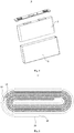
Fig. 1 is a schematic diagram of an exploded structure of a secondary battery according to an embodiment of the present application; -
Fig. 2 is a schematic cross-sectional structure diagram of an electrode assembly according to an embodiment of the present application; -
Fig. 3 is a flowchart of manufacturing an electrode assembly of a secondary battery according to an embodiment of the present application; -
Fig. 4 is a schematic structural diagram of an apparatus for manufacturing an electrode assembly of a secondary battery according to an embodiment of the present application. - In the drawings, the drawings are not drawn according to actual scale.
- 10. secondary battery; 11. case; 12. electrode assembly; 121. positive electrode plate; 122. first separator; 123. negative electrode plate; 124. second separator; 20. positive electrode composite plate body; 30. negative electrode composite plate body; 99. joining position; 100. apparatus; 101. positive electrode feeding device; 102. first separator feeding device; 103. first joining device; 104. negative electrode feeding device; 105. second separator feeding device; 106. second joining device; 107. winding device; 107a. winding needle; 107b, rotating base; 107c. positive electrode roll-in guide roller group; 107d. negative electrode roll-in guide roller group; 108. tension adjustment device; 109. positive electrode plate cutter; 110. negative electrode plate cutter; 111. first dust removal device; 112, second dust removal device; 113. separator cutter; 114. first glue pasting device; 115. second glue pasting device; 116. first detection device; 117. second detection device; 118. first correction device; 119. second correction device.
- The following describes the implementation of the present application in further detail with reference to the accompanying drawings and examples. The detailed description and drawings of the following embodiments are used to exemplarily illustrate the principle of the present application, but in no way to limit the scope of the present application, that is, the present application is not limited to the described embodiments.
- In the description of the present application, it should be noted that, unless otherwise specified, "plurality" means more than two; the orientation or positional relationship indicated by the terms "upper", "lower", "left", "right", "inner", "outside", etc. is only for the convenience of describing the present application and simplifying the description, and does not indicate or imply that the device or element referred to must have a specific orientation, and must be constructed and operated in a specific orientation, and therefore cannot be understood as a limitation to the present application. In addition, the terms "first", "second", "third", etc. are only used for descriptive purposes, and cannot be understood as indicating or implying relative importance. The term "vertical" does not require "vertical" strictly, but within the allowable error range. The term "parallel" does not require "parallel" strictly, but within the allowable error range.
- The orientation words appearing in the following description are all directions shown in the figures, and do not limit the specific structure of the present application. In the description of the present application, it should also be noted that, unless otherwise clearly defined and limited, the terms "mounting", "to be connected with", and "connecting" should be understood in a broad sense and for example, may be a fixed connection or a detachable connection, or integral connection; may be directly connected or indirectly connected through an intermediate medium. For the skilled person in the art, the specific meaning of the above-mentioned terms in the present application can be understood according to specific circumstances.
- In order to better understand the present application, the following describes embodiments of the present application in conjunction with
Figs. 1 to 4 . - Referring to
Fig. 1 , embodiments of the present application provide asecondary battery 10. Thesecondary battery 10 includes acase 11, anelectrode assembly 12 provided in thecase 11, and a top cover assembly that is hermetically connected to thecase 11. Thecase 11 in the embodiment of the present application has a square structure or other shapes. Thecase 11 has an internal space for accommodating theelectrode assembly 12 and the electrolyte, and an opening communicating with the internal space. Thecase 11 may be made of materials such as aluminum, aluminum alloy, or plastic. - As shown in
Fig. 2 , theelectrode assembly 12 of the embodiment of the present application includes apositive electrode plate 121, anegative electrode plate 123 and a separator, wherein the separator is an insulator between thepositive electrode plate 121 and thenegative electrode plate 123. Theelectrode assembly 12 has a main body and tabs. The main body of the present embodiment has a flat structure as a whole, which has a predetermined thickness, height, and width. The active material of thepositive electrode plate 121 is coated on the coated area of thepositive electrode plate 121, and the active material of thenegative electrode plate 123 is coated on the coated area of thenegative electrode plate 123. The uncoated area extending from the coated area of the main body is used as a tab. Theelectrode assembly 12 includes two tabs, namely a positive electrode tab and a negative electrode tab. The positive electrode tab extends from the coated area of thepositive electrode plate 121, and the negative electrode tab extends from the coated area of thenegative electrode plate 123. - Referring to
Fig. 3 , embodiments of the present application provide a method for manufacturing anelectrode assembly 12 of asecondary battery 10, which includes the following steps: - the
positive electrode plate 121 and thefirst separator 122 are joined to form a positive electrodecomposite plate body 20; - the
negative electrode plate 123 and thesecond separator 124 are joined to form a negative electrodecomposite plate body 30; - the positive electrode
composite plate body 20 and the negative electrodecomposite plate body 30 are wound together to form theelectrode assembly 12. Thepositive electrode plate 121 and thenegative electrode plate 123 included by thewound electrode assembly 12 are disposed to isolate from each other through thefirst separator 122 and thesecond separator 124. - In an embodiment, the
positive electrode plate 121 and thefirst separator 122 may complete the joining in a composite manner such as electrostatic adsorption, hot pressing joining or glue pasting joining. Thepositive electrode plate 121 and thefirst separator 122 are laminated on each other along the thickness direction of thepositive electrode plate 121. Thenegative electrode plate 123 and thesecond separator 124 can complete the joining in a composite manner such as electrostatic adsorption, plasma adsorption, hot pressing joining or glue pasting joining. Thenegative electrode plate 123 and thesecond separator 124 are laminated on each other in the thickness direction of thenegative electrode plate 123. - In the embodiment of the present application, before the winding process is performed, the
positive electrode plate 121 and thefirst separator 122 are joined in advance, and thenegative electrode plate 123 and thesecond separator 124 are joined, so that thepositive electrode plate 121 and thefirst separator 122 are connected to each other to form a whole, and thenegative electrode plate 123 and thesecond separator 124 are connected to each other to form a whole. Then, the positive electrodecomposite plate body 20 and the negative electrodecomposite plate body 30 are separately transported to the winding station. Thepositive electrode plate 121 and thenegative electrode plate 123 are respectively driven by thefirst separator 122 and thesecond separator 124 to enter the winding process. In this way, in contrast to the processing manner that thepositive electrode plate 121, thenegative electrode plate 123, and the separator enter the winding process independently, the method for manufacturing theelectrode assembly 12 of thesecondary battery 10 according to the embodiment of the present application, on the one hand, can effectively reduce the total number of plate body entering into the winding process. Thus it is beneficial to reducing the difficulty in alignment of thepositive electrode plate 121, thenegative electrode plate 123 and the separator, reducing the possibility of thepositive electrode plate 121 and thenegative electrode plate 123 being misaligned with each other, and improving the winding alignment accuracy. Here, alignment means that thepositive electrode plate 121, thenegative electrode plate 123, and the separator are aligned with each other in their respective width directions. On the other hand, it can reduce the possibility of that thepositive electrode plate 121 and thenegative electrode plate 123 may be folded or wrinkled when entering into the winding process, which effective improves the yield of theelectrode assembly 12; moreover, thepositive electrode plate 121, thenegative electrode plate 123 and the separator may not be provided with a roll-in auxiliary mechanism, such as a merging film roller group or a rolling feeding component, for guiding thepositive electrode plate 121 and thenegative electrode plate 123 to be rolled in in the upstream close to the winding station, which is beneficial to reducing the number of parts used, simplifying the overall structure of the corresponding winding apparatus, and at the same time improving the efficiency of winding operation. - In an embodiment, before the joining between the
positive electrode plate 121 and thefirst separator 122 is completed, a cutting off process is performed for thepositive electrode plate 121 in the upstream of the joining position of thepositive electrode plate 121 and thefirst separator 122. The joiningposition 99 of thepositive electrode plate 121 and thefirst separator 122 is far away from the winding station. Therefore, the cutting off process is performed for thepositive electrode plate 121 in the upstream of the joiningposition 99, which can further effectively reduce the possibility of a short circuit between thepositive electrode plate 121 and thenegative electrode plate 123 caused by the dust piercing the separator due to the dust generated during the cutting off process to be rolled in. After the cutting off process is performed for thepositive electrode plate 121, thepositive electrode plate 121 forms a composite ending end close to the joiningposition 99 and a composite starting end far away from the joiningposition 99 and for winding thenext electrode assembly 12 on two sides of the cutting off position, respectively. In an exemplary embodiment, the cutting off process may be performed by a mechanical cutter or a laser cutter. - In an embodiment, before the joining of the
negative electrode plate 123 and thesecond separator 124 is completed, a cutting off process is performed for thenegative electrode plate 123 in the upstream of the joiningposition 99 of thenegative electrode plate 123 and thesecond separator 124. The joiningposition 99 of thenegative electrode plate 123 and thesecond separator 124 is far away from the winding station. Therefore, the cutting off process is performed for thenegative electrode plate 123 in the upstream of the joiningposition 99, which can further effectively reduce the possibility of a short circuit between thepositive electrode plate 121 and thenegative electrode plate 123 caused by the dust piercing the separator due to the dust generated during the cutting off process to be rolled in. After the cutting off process is performed for thenegative electrode plate 123, thenegative electrode plate 123 forms a composite ending end close to the joiningposition 99 and a composite starting end far away from the joiningposition 99 and for winding thenext electrode assembly 12 on two sides of the cutting off place, respectively. In an exemplary embodiment, the cutting off process may be performed by a mechanical cutter or a laser cutter. - In an exemplary embodiment, before the joining of the
positive electrode plate 121 and thefirst separator 122 is completed, a cutting off process is performed for thepositive electrode plate 121 in the upstream of the joiningposition 99 of thepositive electrode plate 121 and thefirst separator 122, and at the same time before the joining of thenegative electrode plate 123 and thesecond separator 124 is completed, a cutting off process is performed for thenegative electrode plate 123 in the upstream of the joiningposition 99 of thenegative electrode plate 123 and thesecond separator 124. - In an embodiment, in the upstream of the joining
position 99 of thepositive electrode plate 121 and thefirst separator 122, a dust removal process is performed for thepositive electrode plate 121 before joined, so as to remove dust generated during the cutting off process of thepositive electrode plate 121 or remove the dust that enters the area of thepositive electrode plate 121 close to the joiningposition 99 from the external environment, and reduce the possibility that the dust will follow thepositive electrode plate 121, remain in the positive electrodecomposite plate body 20 formed after the joining is completed and follow the positive electrodecomposite plate body 20 to be rolled in. In another embodiment, in the upstream of the joiningposition 99 of thepositive electrode plate 121 and thefirst separator 122, the dust removal process is performed for thefirst separator 122 before joined to remove the dust that enters the area of thefirst separator 122 close to the joiningposition 99 from the external environment and reduce the possibility that the dust will follow thefirst separator 122, remain in the positive electrodecomposite plate body 20 formed after the joining is completed and follow the positive electrodecomposite plate body 20 to be rolled in. In an exemplary embodiment, in the upstream of the joiningposition 99 of thepositive electrode plate 121 and thefirst separator 122, a dust removal process is simultaneously performed for thepositive electrode plate 121 and thefirst separator 122 before joined. - In an embodiment, in the upstream of the joining
position 99 of thenegative electrode plate 123 and thesecond separator 124, a dust removal process is performed for thenegative electrode plate 123 before joined, so as to remove dust generated during the cutting off process of thenegative electrode plate 123 or remove the dust that enters the area of thenegative electrode plate 123 close to the joiningposition 99 from the external environment, and reduce the possibility that the dust will follow thenegative electrode plate 123, remain in the negative electrodecomposite plate body 30 formed after the joining is completed and follow the negative electrodecomposite plate body 30 to be rolled in. In another embodiment, in the upstream of the joiningposition 99 of thenegative electrode plate 123 and thesecond separator 124, a dust removal process is performed for thesecond separator 124 before joined to remove the dust that enters the area of thesecond separator 124 close to the joiningposition 99 from the external environment, and reduce the possibility that the dust will follow thesecond separator 124, remain in the negative electrodecomposite plate body 30 formed after the joining is completed and follow the negative electrodecomposite plate body 30 to be rolled in. In an exemplary embodiment, in the upstream of the joiningposition 99 of thenegative electrode plate 123 and thesecond separator 124, the dust removal process is simultaneously performed for thenegative electrode plate 123 and thesecond separator 124 before joined. - The
positive electrode plate 121 to be joined has a composite starting end. After thepositive electrode plate 121 is cut off after one winding process is completed, a composite ending end and a composite starting end for the next winding process are formed. In the step that thepositive electrode plate 121 and thefirst separator 122 are joined to form the positive electrode composite plate body 20: the composite starting end or the composite ending end of thepositive electrode plate 121 is adhesively connected to thefirst separator 122, thereby effectively reducing the possibility that during the composite process, the conveying process or the winding process, the composite starting end or the composite ending end of thepositive electrode plate 121 joined to thefirst separator 122 may be folded or wrinkled. In an example, the composite starting end or composite ending end of thepositive electrode plate 121 is adhesively connected to thefirst separator 122 by an adhesive tape. In an exemplary embodiment, the composite starting end and the composite ending end of thepositive electrode plate 121 are adhesively connected to thefirst separator 122. - The
negative electrode plate 123 to be joined has a composite starting end. After thenegative electrode plate 123 is cut off after one winding process is completed, a composite ending end and a composite starting end for the next winding process are formed. In the step that thenegative electrode plate 123 and thesecond separator 124 are joined to form the negative electrode composite plate body 30: the composite starting end or the composite ending end of thenegative electrode plate 123 is adhesively connected to thesecond separator 124, thereby effectively reducing the possibility that during the composite process, the conveying process or the winding process, the composite starting end or the composite ending end of thenegative electrode plate 123 joined to thesecond separator 124 may be folded or wrinkled. In an example, the composite starting end or composite ending end of thenegative electrode plate 123 is adhesively connected to thesecond separator 124 by an adhesive tape. In an exemplary embodiment, the composite starting end and the composite ending end of thenegative electrode plate 123 are adhesively connected to thesecond separator 124. - In the step of winding the positive electrode
composite plate body 20 and the negative electrodecomposite plate body 30 together to form theelectrode assembly 12, the positive electrodecomposite plate body 20 or the negative electrodecomposite plate body 30 is transported from bottom to top to the winding station and the winding process is performed. Here, "from bottom to top" refers to the vertical direction as the reference direction. Since thepositive electrode plate 121 and thenegative electrode plate 123 of the embodiment of the present application are joined with thefirst separator 122 and thesecond separator 124 respectively, thepositive electrode plate 121 and thenegative electrode plate 123 follow thefirst separator 122 and thesecond separator 124 respectively to go through the winding process directly. Therefore, the positive electrodecomposite plate body 20 or the negative electrodecomposite plate body 30 of the embodiment of the present application can adopt the manner of conveying from bottom to top, and meanwhile the composite starting end and the composite ending end of thepositive electrode plate 121 or thenegative electrode plate 123 will not be put in a hanging down state under its own gravity, which otherwise results in fold or wrinkle. In addition, it can further make that during the conveying process of the positive electrodecomposite plate body 20 or the negative electrodecomposite plate body 30, the dust carried will be separated and fall under the action of its own gravity, thereby reducing the possibility that the dust will follow the positive electrodecomposite plate body 20 or the negative electrodecomposite plate body 30 to enter into theelectrode assembly 12 resulting from winding and affect the use safety of theelectrode assembly 12. In an exemplary embodiment, the positive electrodecomposite plate body 20 and the negative electrodecomposite plate body 30 are conveyed from bottom to top to the winding station and the winding process is performed. - The method for manufacturing the
electrode assembly 12 of thesecondary battery 10 in the embodiment of the present application adopts the manner that thepositive electrode plate 121 and thefirst separator 122 are joined and thenegative electrode plate 123 and thesecond separator 124 are joined in advance, and then thecomposite plate body 20 and the negative electrodecomposite plate body 30 are wound. Therefore, compared with the manner that thepositive electrode plate 121, thenegative electrode plate 123, and the two separators are wound independently, the method in the embodiment of the present application is no longer necessary to provide a roll-in auxiliary mechanism for guiding thepositive electrode plate 121, thenegative electrode plate 123 and the two separators to be rolled in, thereby reducing the number of parts used, at the same time more easily ensuring the accuracy of alignment of thepositive electrode plate 121, thenegative electrode plate 123, thefirst separator 122 and thesecond separator 124, and reducing the possibility of affecting the electrical performance of theelectrode assembly 12 due to misalignment of thepositive electrode plate 121, thenegative electrode plate 123, and the separator. - Referring to
Fig. 4 , embodiments of the present application provide anapparatus 100 for manufacturing theelectrode assembly 12 of thesecondary battery 10, which can be used to implement the method for manufacturing theelectrode assembly 12 of thesecondary battery 10 in the foregoing embodiments. Theapparatus 100 of the present embodiment includes a positiveelectrode feeding device 101, a firstseparator feeding device 102, a first joiningdevice 103, a negativeelectrode feeding device 104, a secondseparator feeding device 105, a second joiningdevice 106, and a windingdevice 107. - The positive
electrode feeding device 101 is used to mount and fix thepositive electrode plate 121 material roll, and then output thepositive electrode plate 121 through the unwinding machine. Thepositive electrode plate 121 is driven by the transfer roller group to move toward the joiningposition 99. The firstseparator feeding device 102 is used to mount and fix the separator material roll, and then output thefirst separator 122 through the unwinding machine. Thefirst separator 122 moves toward the joiningposition 99 under the driving of the conveying roller group. The first joiningdevice 103 is arranged in the downstream of the positiveelectrode feeding device 101 and the firstseparator feeding device 102. Both thepositive electrode plate 121 and thefirst separator 122 are transported to the first joiningdevice 103, and then the first joiningdevice 103 joins thepositive electrode plate 121 and thefirst separator 122 to form the positive electrodecomposite plate body 20. In an example, the first joiningdevice 103 includes a hot pressing mechanism. Thepositive electrode plate 121 and thefirst separator 122 are joined through hot pressing by a hot pressing mechanism. In another example, the first joiningdevice 103 includes an electrostatic generator. Thepositive electrode plate 121 and thefirst separator 122 are joined through electrostatic adsorption. In yet another example, the first joiningdevice 103 includes a glue pasting mechanism. Thepositive electrode plate 121 and thefirst separator 122 are joined via pasting glue. Thepositive electrode plate 121 and thefirst separator 122 are laminated and joined on each other in the thickness direction. - The negative
electrode feeding device 104 is used to mount and fix thenegative electrode plate 123 material roll, and then output thenegative electrode plate 123 through the unwinding machine. Thenegative electrode plate 123 moves toward the joiningposition 99 under the driving of the transfer roller group. The secondseparator feeding device 105 is used to mount and fix the separator material roll, and then output thesecond separator 124 through the unwinding machine. Thesecond separator 124 moves toward the joiningposition 99 under the driving of the conveying roller group. The second joiningdevice 106 is arranged downstream of the negativeelectrode feeding device 104 and the secondseparator feeding device 105. Both thenegative electrode plate 123 and thesecond separator 124 are transported to the second joiningdevice 106, and then the second joiningdevice 106 joins thenegative electrode plate 123 and thesecond separator 124 to form a negativecomposite plate body 30. In an example, the second joiningdevice 106 includes a hot pressing mechanism. Thenegative electrode plate 123 and thesecond separator 124 are joined through hot pressing by a hot pressing mechanism. In another example, the second joiningdevice 106 includes an electrostatic generator. Thenegative electrode plate 123 and thesecond separator 124 are joined through electrostatic adsorption. In yet another example, the second joiningdevice 106 includes a glue pasting mechanism. Thenegative electrode plate 123 and thesecond separator 124 are joined via pasting glue. Thenegative electrode plate 123 and thesecond separator 124 are superimposed and joined on each other in the thickness direction. - The winding
device 107 is provided in the downstream of the first joiningdevice 103 and the second joiningdevice 106. The positive electrodecomposite plate body 20 and the negative electrodecomposite plate body 30 are conveyed to the windingdevice 107. The windingdevice 107 winds the positive electrodecomposite plate body 20 and the negative electrodecomposite plate body 30 to produce theelectrode assembly 12. - In an embodiment, the first joining
device 103 and the second joiningdevice 106 are symmetrically arranged on both sides of the windingdevice 107, so as to ensure the consistency of the positions of the respective joiningposition 99 of thepositive electrode plate 121 and thenegative electrode plate 123 and the consistency of the roll-in positions of the positive electrodecomposite plate body 20 and the negative electrodecomposite plate body 30 formed after joined, which is beneficial to improving the alignment accuracy of the woundpositive electrode plate 121 and thenegative electrode plate 123. - In an embodiment, the
apparatus 100 further includes atension adjustment device 108. Thetension adjusting device 108 is arranged in the upstream of the windingdevice 107 and is used to adjust the tension degree of the positive electrodecomposite plate body 20 or the negative electrodecomposite plate body 30. - In the
apparatus 100 for manufacturing theelectrode assembly 12 of thesecondary battery 10 in the embodiment of the present application, thepositive electrode plate 121 and thefirst separator 122 are joined in advance by the first joiningdevice 103, and thenegative electrode plate 123 and thesecond separator 122 are joined in advance by the second joiningdevice 106, so that thepositive electrode plate 121 and thefirst separator 122 are connected to each other to form a whole, and thenegative electrode plate 123 and thesecond separator 124 are connected to each other to form a whole. Then, the positive electrodecomposite plate body 20 and the negative electrodecomposite plate body 30 are separately conveyed to the winding station of the windingdevice 107 to complete the winding operation. Thepositive electrode plate 121 and thenegative electrode plate 123 are respectively driven by thefirst separator 122 and thesecond separator 124 to enter the winding process. In this way, in contrast to the processing manner that thepositive electrode plate 121, thenegative electrode plate 123, and the separator enter the winding process independently, theapparatus 100 for manufacturing theelectrode assembly 12 of thesecondary battery 10 of the embodiment of the present application, on the one hand, can effectively reduce the total number of the plate bodies entering into the winding process, which is beneficial to reducing the difficulty in alignment of thepositive electrode plate 121, thenegative electrode plate 123 and the separator, reducing the possibility of misalignment of thepositive electrode plate 121 and thenegative electrode plate 123, and improving the accuracy of winding alignment. On the other hand, it can reduce the possibility that the positive electrode plate and thenegative electrode plate 123 may be folded or wrinkled when entering the winding process, which is beneficial to improving the yield of theelectrode assembly 12; moreover, thepositive electrode plate 121, thenegative electrode plate 123 and the separator may not be provided with a roll-in auxiliary mechanism for guiding thepositive electrode plate 121 and thenegative electrode plate 123 to be rolled in in the upstream close to the windingdevice 107, which is beneficial to reducing the number of parts used, simplifying the overall structure of theapparatus 100, and improving the efficiency of winding operation at the same time. - In an embodiment, the
apparatus 100 further includes a positiveelectrode plate cutter 109 for cutting off thepositive electrode plate 121. The positiveelectrode plate cutter 109 is arranged in the upstream of the first joiningdevice 103. The positiveelectrode plate cutter 109 is used to cut off thepositive electrode plate 121 in the upstream of the joiningposition 99 of thepositive electrode plate 121 and thefirst separator 122. In an example, the positiveelectrode plate cutter 109 includes a cutter and a cutter seat. Thepositive electrode plate 121 passes between the cutter and the cutter holder. When it is necessary to cut off thepositive electrode plate 121, the cutter and the cuter seat come close to each other to cut off thepositive electrode plate 121. In an example, the positiveelectrode plate cutter 109 may be a laser cutter, and thepositive electrode plate 121 is cut by laser. Before the joining of thepositive electrode plate 121 and thefirst separator 122 is completed, a cutting off process is performed for thepositive electrode plate 121 in the upstream of the joiningposition 99 of thepositive electrode plate 121 and thefirst separator 122. The joiningposition 99 between thepositive electrode plate 121 and thefirst separator 122 is far away from the winding station. Therefore, the cutting off process is performed for thepositive electrode plate 121 in the upstream of the joiningposition 99, which can further effectively reduce the possibility of a short circuit between thepositive electrode plate 121 and thenegative electrode plate 123 caused by the dust piercing the separator due to the dust generated during the cutting off process to be rolled in. In an embodiment, theapparatus 100 further includes a negativeelectrode plate cutter 110 for cutting thenegative electrode plate 123. The negativeelectrode plate cutter 110 is arranged in the upstream of the second joiningdevice 106. The negativeelectrode plate cutter 110 is used to cut off thenegative electrode plate 123 in the upstream of the joiningposition 99 of thenegative electrode plate 123 and thesecond separator 124. In an example, the negativeelectrode plate cutter 110 includes a cutter and a cutter seat. Thenegative electrode plate 123 passes between the cutter and the cutter seat. When it is necessary to cut off thenegative electrode plate 123, the cutter and the cutter seat come close to each other to cut off thenegative electrode plate 123. In an example, the negativeelectrode plate cutter 110 may be a laser cutter, and thenegative electrode plate 123 is cut by laser. Before the joining of thenegative electrode plate 123 and thesecond separator 124 is completed, a cutting off process is performed for thenegative electrode plate 123 in the upstream of the joiningposition 99 of thenegative electrode plate 123 and thesecond separator 124. The joiningposition 99 of thenegative electrode plate 123 and thesecond separator 124 is far away from the winding station. Therefore, the cutting off process is performed for thenegative electrode plate 123 in the upstream of the joiningposition 99, which can further effectively reduce the possibility of a short circuit between thepositive electrode plate 121 and thenegative electrode plate 123 caused by the dust piercing the separator due to the dust generated during the cutting off process to be rolled in. In an exemplary embodiment, theapparatus 100 includes a positiveelectrode plate cutter 109 for cutting off thepositive electrode plate 121 and a negativeelectrode plate cutter 110 for cutting off thenegative electrode plate 123. - In an embodiment, the
apparatus 100 further includes a firstdust removal device 111. The firstdust removal device 111 is arranged in the upstream of the first joiningdevice 103 and is used to perform a dust removal process for thepositive electrode plate 121 and/or thefirst separator 122 before joined. The firstdust removal device 111 is close to the positiveelectrode plate cutter 109. In the upstream of the joiningposition 99 of thepositive electrode plate 121 and thefirst separator 122, the firstdust removal device 111 performs a dust removal process for thepositive electrode plate 121 and/or thefirst separator 122 before joined, so as to remove the dust generated during the cutting off process of thepositive electrode plate 121 or remove the dust entering the area near the joiningposition 99 from the external environment, thus reducing the possibility that the dust will remain in the positivecomposite plate body 20 formed after the joining is completed and follow the positivecomposite plate body 20 to be rolled in. In an example, the firstdust removal device 111 includes a dust suction tube and a negative pressure generator connected to the dust suction tube. In an embodiment, theapparatus 100 further includes a seconddust removal device 112. The seconddust removal device 112 is arranged in the upstream of the second joiningdevice 106 and is used to perform a dust removal process for thenegative electrode plate 123 and/or thesecond separator 124 before joined. The seconddust removal device 112 is close to the negativeelectrode plate cutter 110. In the upstream of the joiningposition 99 of thenegative electrode plate 123 and thesecond separator 124, the seconddust removal device 112 performs a dust removal process for thenegative electrode plate 123 and/or thesecond separator 124 before joined, so as to remove the dust generated during the cutting off process of thenegative electrode plate 123 or remove the dust entering the area near the joiningposition 99 from the external environment, thus reducing the possibility that the dust will remain in the negative electrodecomposite plate body 30 formed after the joining is completed and follow the negativecomposite plate body 30 to be rolled in. In an example, the seconddust removal device 112 includes a dust suction tube and a negative pressure generator connected to the dust suction tube. - In an embodiment, the winding
device 107 includes a windingneedle 107a, a positive electrode roll-inguide roller group 107c, and a negative electrode roll-inguide roller group 107d. Both the positive electrode roll-inguide roller group 107c and the negative electrode roll-inguide roller group 107d are arranged in the upstream of the windingneedle 107a. In an example, both the positive electrode roll-inguide roller group 107c and the negative electrode roll-inguide roller group 107d are arranged below the windingneedle 107a. The positive electrode roll-inguide roller group 107c directly conveys the positive electrodecomposite plate body 20 from bottom to top to the windingneedle 107a. The negative electrode roll-inguide roller group 107d directly conveys the negative electrodecomposite plate body 30 from bottom to top to the windingneedle 107a. In an example, the windingneedle 107a includes two half shafts that can be close to or away from each other. The starting ends of thefirst separator 122 and thesecond separator 124 are pre-clamped between the two half shafts, and then the windingneedle 107a is rotated by a predetermined number of turns to wind thefirst separator 122 and thesecond separator 124 with a predetermined length. Then, thepositive electrode plate 121 and thenegative electrode plate 123 are respectively driven by thefirst separator 122 and thesecond separator 124 to enter into the windingneedle 107a for winding. After a predetermined length of thepositive electrode plate 121 and thenegative electrode plate 123 are wound, thepositive electrode plate 121 and thenegative electrode plate 123 are cut off. After thepositive electrode plate 121 and thenegative electrode plate 123 are wound, the windingneedle 107a continues to rotate by a predetermined number of turns to continue winding thefirst separator 122 and thesecond separator 124. After thefirst separator 122 and thesecond separator 124 of a predetermined length are wound, thefirst separator 122 and thesecond separator 124 are cut off, and the winding operation is finally completed. The two half shafts are opened, and theelectrode assembly 12 is removed from the windingneedle 107a to complete the feeding. In an example, the windingdevice 107 includes arotating base 107b and two windingneedles 107a arranged on the rotatingbase 107b at intervals. After the first windingneedle 107a completes the winding operation, the rotatingbase 107b rotates, so that the first windingneedle 107a rotates to the feeding station, and the second windingneedle 107a rotates to the winding station. Thesecond coiling needle 107a clamps thefirst separator 122 and thesecond separator 124, and then thefirst separator 122 and thesecond separator 124 are cut off between the two windingneedles 107a by theseparator cutter 113. The two windingneedles 107a are used in cycle to perform winding operation, so that in the process of winding a plurality ofelectrode assemblies 12 using theapparatus 100 for manufacturing theelectrode assembly 12 of thesecondary battery 10, the roll-in operation is required to perform on thefirst separator 122 and thesecond separator 124 only once in the initial stage, and then the two windingneedles 107a alternately clamp thefirst separator 122 and thesecond separator 124 to continuously perform the winding operation. The roll-in operation is no longer required to perform on thefirst separator 122 and thesecond separator 124, thereby effectively improving the efficiency of the winding operation. The number of windingneedles 107a is not limited to the above-mentioned two, and may be three or more. Each windingneedle 107a can be switched between the unloading station and the winding station under the driving of therotating base 107b. In an example, the positive electrode roll-inguide roller group 107c and the negative electrode roll-inguide roller group 107d are symmetrically arranged on both sides of the windingneedle 107a in the winding station, so as to ensure the consistency of the roll-in positions of the positive electrodecomposite plate body 20 and the negative electrodecomposite plate body 30, which is beneficial to improving the alignment accuracy of thepositive electrode plate 121 and thenegative electrode plate 123 after the winding. - In an embodiment, the
apparatus 100 includes a firstglue pasting device 114. The firstglue pasting device 114 is arranged in the downstream of the first joiningdevice 103. The composite starting end or the composite ending end of thepositive electrode plate 121 is adhesively connected to thefirst separator 122 through the firstglue pasting device 114, thereby further effectively reducing the possibility that the composite starting end or the composite ending end of thepositive electrode plate 121 joined to thefirst separator 122 nay be folded or wrinkled during the composite process, conveying process or winding process. In an exemplary embodiment, the composite starting end and the composite ending end of thepositive electrode plate 121 are adhesively connected to thefirst separator 122. In an example, the firstglue pasting device 114 includes an adhesive tape output mechanism, an adhesive tape sticking mechanism, and an adhesive tape cutting-off mechanism. At least one of the composite starting end and the composite ending end of thepositive electrode plate 121 is adhesively connected to thefirst separator 122 by an adhesive tape. In an embodiment, theapparatus 100 includes a secondglue pasting device 115. The secondglue pasting device 115 is arranged in the downstream of the second joiningdevice 106. The composite starting end or the composite ending end of thenegative electrode plate 123 is adhesively connected to thesecond separator 124 by the secondglue pasting device 115, thereby further effectively reducing the possibility that the composite starting end or the composite ending end of thenegative electrode plate 123 joined to thesecond separator 124 nay be folded or wrinkled during the composite process, conveying process or winding process. In an exemplary embodiment, the composite starting end and the composite ending end of thenegative electrode plate 123 are adhesively connected to thesecond separator 124. In an example, the secondglue pasting device 115 includes an adhesive tape output mechanism, an adhesive tape sticking mechanism, and an adhesive tape cutting-off mechanism. The composite starting end or composite ending end of thenegative electrode plate 123 is adhesively connected to thesecond separator 124 by an adhesive tape. In an exemplary embodiment, theapparatus 100 includes a firstglue pasting device 114 and a secondglue pasting device 115. - In an embodiment, the
apparatus 100 further includes afirst detection device 116 for detecting the composite alignment degree of thepositive electrode plate 121 and thefirst separator 122. Thefirst detection device 116 is arranged in the downstream of the first joiningdevice 103 and can detect in real time the alignment degree of thepositive electrode plate 121 and thefirst separator 122 after being joined. When the alignment degree of thepositive electrode plate 121 and thefirst separator 122 meets the accuracy requirements, the positive electrodecomposite plate body 20 can be transported to the windingdevice 107 for winding, which is beneficial to ensuring the yield and quality of thewound electrode assembly 12. In an example, thefirst detection device 116 includes an industrial camera or a photoelectric sensor for detecting the degree of alignment. In an embodiment, theapparatus 100 further includes asecond detection device 117 for detecting the composite alignment degree of thenegative electrode plate 123 and thesecond separator 124. Thesecond detection device 117 is disposed in the downstream of the second joiningdevice 106, and can detect in real time the alignment degree of thenegative electrode plate 123 and thesecond separator 124 after being joined. When the alignment degree of thenegative electrode plate 123 and thesecond separator 124 meets the accuracy requirements, the negative electrodecomposite plate body 30 can be transported to the windingdevice 107 for winding, which is beneficial to ensuring the yield and quality of thewound electrode assembly 12. In an example, thesecond detection device 117 includes an industrial camera or a photoelectric sensor for detecting the degree of alignment. In an exemplary embodiment, theapparatus 100 further includes afirst detection device 116 and asecond detection device 117. - In an embodiment, the
apparatus 100 further includes afirst correction device 118 for adjusting the alignment degree of thepositive electrode plate 121 and thefirst separator 122. Before thepositive electrode plate 121 and thefirst separator 122 are joined, the first correctingdevice 118 adjusts the relative position of thepositive electrode plate 121 and thefirst separator 122 along the width direction of thepositive electrode plate 121, so that thepositive electrode plate 121 and thefirst separator 122 are aligned with each other so as to satisfy product requirements, which is beneficial to improving the yield of thewound electrode assembly 12. In an example, theapparatus 100 includes afirst detection device 116. Thefirst correction device 118 is in communication with thefirst detection device 116. When thefirst detection device 116 detects that the alignment degree between thepositive electrode plate 121 and thefirst separator 122 does not meet the requirements, it sends a signal to thefirst correction device 118, and then thefirst correction device 118 performs a correction action to adjust the alignment degree of thepositive electrode plate 121 and thefirst separator 122. In an embodiment, theapparatus 100 further includes asecond correction device 119 for adjusting the alignment degree of thenegative electrode plate 123 and thesecond separator 124. Before thenegative electrode plate 123 and thesecond separator 124 are joined, the second correctingdevice 119 adjusts the relative position of thenegative electrode plate 123 and thesecond separator 124 along the width direction of thenegative electrode plate 123, so that thenegative electrode plate 123 and thesecond separator 124 are aligned with each other so as to satisfy the product requirements, which is beneficial to improving the yield of thewound electrode assembly 12. In an example, theapparatus 100 includes asecond detection device 117. Thesecond correction device 119 is in communication with thesecond detection device 117. When thesecond detection device 117 detects that the alignment degree between thenegative electrode plate 123 and thesecond separator 124 does not meet the requirements, it sends a signal to the second correctingdevice 119, and then the second correctingdevice 119 performs a correcting action to adjust the alignment degree of thenegative electrode plate 123 and thesecond separator 124. In an exemplary embodiment, theapparatus 100 further includes afirst correction device 118 and asecond correction device 119. - According to the
apparatus 100 for manufacturing theelectrode assembly 12 of thesecondary battery 10 of the embodiment of the present application, thepositive electrode plate 121 and thefirst separator 122, and thenegative electrode plate 123 and thesecond separator 124 are joined to form the positive electrodecomposite plate body 20 and the negative electrodecomposite plate body 30 in advance, so that thepositive electrode plate 121 and thefirst separator 122 are connected as a whole, thenegative electrode plate 123 and thesecond separator 124 are connected as a whole, and then the positive electrodecomposite plate body 20 and the negative electrodecomposite plate body 30 are wound to form theelectrode assembly 12. In this way, on the one hand, theapparatus 100 of the embodiment of the present application does not require that thepositive electrode plate 121, thenegative electrode plate 123 and the separator to be rolled in for winding separately, which can reduce the possibility that thepositive electrode plate 121 and thenegative electrode plate 123 may be folded or wrinkled when they enter the winding process separately, and that thepositive electrode plate 121 and thenegative electrode plate 123 are not aligned with each other, and thus improve the yield of theelectrode assembly 12 effectively. On the other hand, thepositive electrode plate 121, thenegative electrode plate 123 and the separator may not be provided with a roll-in auxiliary mechanism for guiding thepositive electrode plate 121 and thenegative electrode plate 123 to be rolled in in the upstream of the windingdevice 107, which is beneficial to reducing the number of parts used, simplifying the overall structure of theapparatus 100, and at the same time improving the efficiency of winding operation. - Although the present application has been described with reference to the preferred embodiments, without departing from the scope of the present application, various improvements can be made to it and the components therein can be replaced with equivalents. In particular, as long as there is no structural conflict, the various technical features mentioned in the various embodiments can be combined in any manner. The present application is not limited to the specific embodiments disclosed in the text, but includes all technical solutions falling within the scope of the claims.
Claims (15)
- A method for manufacturing an electrode assembly of a secondary battery comprising:joining a positive electrode plate and a first separator to form a positive electrode composite plate body;joining a negative electrode plate and a second separator to form a negative electrode composite plate body;winding the positive electrode composite plate body and the negative electrode composite plate body together to form an electrode assembly, wherein the positive electrode plate and the negative electrode plate are disposed to isolate from each other by the first separator and the second separator.
- The method for manufacturing an electrode assembly of a secondary battery according to claim 1, whereinbefore completing the joining of the positive electrode plate and the first separator, a cutting off process is performed for the positive electrode plate in the upstream of the joining position of the positive electrode plate and the first separator; and/orbefore completing the joining of the negative electrode plate and the second separator, a cutting off process is performed for the negative electrode plate in the upstream of the joining position of the negative electrode plate and the second separator.
- The method for manufacturing an electrode assembly of a secondary battery according to claim 1 or 2, whereinin the upstream of the joining position of the positive electrode plate and the first separator, a dust removal process is performed for the positive electrode plate and/or the first separator before joined; and/orin the upstream of the joining position of the negative electrode plate and the second separator, a dust removal process is performed for the negative electrode plate and/or the second separator before joined.
- The method for manufacturing an electrode assembly of a secondary battery according to any one of claims 1 to 3, whereinin the step of joining the positive electrode plate and the first separator to form a positive electrode composite plate body, a composite starting end and/or a composite ending end of the positive electrode plate is adhesively connected with the first separator; and/orin the step of joining the negative electrode plate and the second separator to form a negative electrode composite plate body, a composite starting end and/or a composite ending end of the negative electrode plate is adhesively connected with the second separator.
- The method for manufacturing an electrode assembly of a secondary battery according to any one of claims 1 to 4, wherein
in the step of winding the positive electrode composite plate body and the negative electrode composite plate body together to form an electrode assembly, the positive electrode composite plate body and/or the negative electrode composite plate body is transported from bottom to top to a winding station and a winding process is performed. - The method for manufacturing an electrode assembly of a secondary battery according to any one of claims 1 to 5, wherein the joining of the positive electrode plate and the first separator can be completed in a composite manner such as electrostatic adsorption, hot pressing joining, or glue pasting joining; and/or
the joining of the negative electrode plate and the second separator can be completed in a composite manner such as electrostatic adsorption, plasma adsorption, hot pressing joining, or glue pasting joining. - An apparatus for manufacturing an electrode assembly of a secondary battery comprising:a positive electrode feeding device for outputting a positive electrode plate;a first separator feeding device for outputting a first separator;a first joining device arranged in the downstream of the positive electrode feeding device and the first separator feeding device, wherein the first joining device can join the positive electrode plate and the first separator to form a positive electrode composite plate body;a negative electrode feeding device for outputting a negative electrode plate;a second separator feeding device for outputting a second separator;a second joining device arranged in the downstream of the negative electrode feeding device and the second separator feeding device, wherein the second joining device can join the negative electrode plate and the second separator to form a negative electrode composite plate body;a winding device arranged in the downstream of the first joining device and the second joining device, wherein the winding device can wind the positive electrode composite plate body and the negative electrode composite plate body to form an electrode assembly.
- The apparatus for manufacturing an electrode assembly of a secondary battery according to claim 7, whereinthe apparatus further comprises a positive electrode plate cutter, the positive electrode plate cutter is arranged in the upstream of the first joining device, and the positive electrode plate cutter is configured for cutting off the positive electrode plate in the upstream of the joining position of the positive electrode plate and the first separator; and/orthe apparatus further comprises a negative electrode plate cutter, the negative electrode plate cutter is arranged in the upstream of the second joining device, and the negative electrode plate cutter is configured for cutting off the negative electrode plate in the upstream of the joining position of the negative electrode plate and the second separator.
- The apparatus for manufacturing an electrode assembly of a secondary battery according to claim 7 or 8, whereinthe apparatus further comprises a first dust removal device, the first dust removal device is arranged in the upstream of the first joining device, and the first dust removal device is configured for performing a dust removal process for the positive electrode plate and/or the first separator before joined; and/orthe apparatus further comprises a second dust removal device, the second dust removal device is arranged in the upstream of the second joining device, and the second dust removal device is configured for performing a dust removal process for the negative electrode plate and/or the second separator before joined.
- The apparatus for manufacturing an electrode assembly of a secondary battery according to any one of claims 6 to 9, wherein
the winding device comprises a winding needle, a positive electrode roll-in guide roller group and a negative electrode roll-in guide roller group, the positive electrode roll-in guide roller group and the negative electrode roll-in guide roller group are both arranged in the upstream of the winding needle, the positive electrode roll-in guide roller group and the negative electrode roll-in guide roller group are both arranged below the winding needle, the positive electrode roll-in guide roller group directly conveys the positive electrode composite plate body from bottom to top to the winding needle, and the negative electrode roll-in guide roller group directly conveys the negative electrode composite plate body from bottom to top to the winding needle. - The apparatus for manufacturing an electrode assembly of a secondary battery according to claim 10, wherein
the winding device further comprises a rotating base and two or more winding needles, and the two or more winding needles arranged on the rotating base at intervals around a rotation axis of the rotating base. - The apparatus for manufacturing an electrode assembly of a secondary battery according to any one of claims 6 to 11, whereinthe apparatus further comprises a first glue pasting device, the first glue pasting device is arranged in the downstream of the first joining device, and the first glue pasting device is configured for joining the composite starting end and/or the composite ending end of the positive electrode plate to the first separator; and/orthe apparatus further comprises a second glue pasting device, the second glue pasting device is arranged in the downstream of the second joining device, and the second glue pasting device is configured for joining the composite starting end and/or the composite ending end of the negative electrode plate to the second separator.
- The apparatus for manufacturing an electrode assembly of a secondary battery according to any one of claims 6 to 12, whereinthe apparatus further comprises a first detection device, the first detection device is arranged in the downstream of the first joining device, and the first detection device is configured for detecting a composite alignment degree of the positive electrode plate and the first separator; and/orthe apparatus further comprises a second detection device, the second detection device is arranged in the downstream of the second joining device, and the second detection device is configured for detecting a composite alignment degree of the negative electrode plate and the second separator .
- The apparatus for manufacturing an electrode assembly of a secondary battery according to claim 13, whereinthe apparatus further comprises a first correction device, the first correction device is arranged in the upstream of the first joining device, and the first correction device is configured for adjusting the relative position of the positive electrode plate and the first separator; and/orthe apparatus further comprises a second correction device, the second correction device is arranged in the upstream of the second joining device, and the second correction device is configured for adjusting the relative position of the negative electrode plate and the second separator.
- The apparatus for manufacturing an electrode assembly of a secondary battery according to any one of claims 6 to 14, further comprising a tension adjusting device, wherein the tension adjusting device is disposed in the upstream of the winding device for adjusting a degree of tension of the positive electrode composite plate body or the negative electrode composite plate body.
Applications Claiming Priority (2)
| Application Number | Priority Date | Filing Date | Title |
|---|---|---|---|
| CN201910957293.5A CN112310461B (en) | 2019-10-10 | 2019-10-10 | Method and apparatus for manufacturing electrode assembly of secondary battery |
| PCT/CN2020/114503 WO2021068705A1 (en) | 2019-10-10 | 2020-09-10 | Method for fabricating electrode assembly of secondary battery and device |
Publications (4)
| Publication Number | Publication Date |
|---|---|
| EP3930062A1 true EP3930062A1 (en) | 2021-12-29 |
| EP3930062A4 EP3930062A4 (en) | 2022-06-15 |
| EP3930062C0 EP3930062C0 (en) | 2023-08-02 |
| EP3930062B1 EP3930062B1 (en) | 2023-08-02 |
Family
ID=74485612
Family Applications (1)
| Application Number | Title | Priority Date | Filing Date |
|---|---|---|---|
| EP20874982.0A Active EP3930062B1 (en) | 2019-10-10 | 2020-09-10 | Method and apparatus for manufacturing electrode assembly of secondary battery |
Country Status (6)
| Country | Link |
|---|---|
| US (1) | US11961955B2 (en) |
| EP (1) | EP3930062B1 (en) |
| JP (1) | JP7379690B2 (en) |
| KR (1) | KR102646568B1 (en) |
| CN (1) | CN112310461B (en) |
| WO (1) | WO2021068705A1 (en) |
Cited By (1)
| Publication number | Priority date | Publication date | Assignee | Title |
|---|---|---|---|---|
| EP4276962A4 (en) * | 2022-03-18 | 2024-11-27 | Battero Tech Corporation Limited | BATTERY WINDING METHOD AND APPARATUS |
Families Citing this family (14)
| Publication number | Priority date | Publication date | Assignee | Title |
|---|---|---|---|---|
| KR102757891B1 (en) * | 2019-11-13 | 2025-01-22 | 주식회사 엘지에너지솔루션 | Electrode assembly manufacturing method and electrode assembly manufactured manufacturing device |
| CN113422113B (en) * | 2021-06-04 | 2022-07-05 | 深圳赛骄阳能源科技股份有限公司 | Method for manufacturing special-shaped lithium ion battery |
| CN115763932A (en) * | 2021-09-02 | 2023-03-07 | 宁德时代新能源科技股份有限公司 | Battery cell manufacturing device and method |
| CN115810713B (en) * | 2021-10-18 | 2025-03-07 | 宁德时代新能源科技股份有限公司 | Pole piece, assembly, monomer, battery, device, pole piece manufacturing method and system |
| CN116014362B (en) * | 2021-10-21 | 2025-03-07 | 宁德时代新能源科技股份有限公司 | Electrode assembly and related preparation device, battery cell and battery |
| CN116314999A (en) * | 2021-12-21 | 2023-06-23 | 宁德时代新能源科技股份有限公司 | Electrode assembly manufacturing apparatus and manufacturing method |
| KR20230106231A (en) * | 2022-01-06 | 2023-07-13 | 주식회사 엘지에너지솔루션 | Device for connecting eletore |
| WO2023197167A1 (en) * | 2022-04-12 | 2023-10-19 | 宁德时代新能源科技股份有限公司 | Control method and stacking system |
| CN114843618B (en) * | 2022-04-19 | 2025-12-02 | 三一技术装备有限公司 | Composite lamination equipment and production line |
| CN114937819A (en) * | 2022-04-26 | 2022-08-23 | 上海兰钧新能源科技有限公司 | Lithium ion battery pole piece preparation device and method |
| CN114883625A (en) * | 2022-05-10 | 2022-08-09 | 东莞市雅康精密机械有限公司 | Composite battery winding equipment |
| WO2024039221A1 (en) * | 2022-08-18 | 2024-02-22 | 주식회사 엘지에너지솔루션 | Jelly-roll type electrode assembly and method for manufacturing same |
| CN115763935B (en) * | 2022-11-18 | 2026-01-13 | 广东风华新能源股份有限公司 | Battery hot pressing rubber coating device |
| JP7778099B2 (en) * | 2023-02-01 | 2025-12-01 | プライムプラネットエナジー&ソリューションズ株式会社 | Method for manufacturing a wound electrode body, method for manufacturing an electricity storage device including the wound electrode body, and apparatus for manufacturing the wound electrode body |
Family Cites Families (28)
| Publication number | Priority date | Publication date | Assignee | Title |
|---|---|---|---|---|
| US2081943A (en) * | 1934-05-21 | 1937-06-01 | Arthur D Lund | Grid pasting machine |
| JPH0613129U (en) * | 1992-07-24 | 1994-02-18 | 日本ケミコン株式会社 | Winding device for capacitor element |
| JP2002298924A (en) * | 2001-03-30 | 2002-10-11 | Toray Eng Co Ltd | Secondary battery, secondary battery manufacturing method, and secondary battery manufacturing apparatus |
| KR100614390B1 (en) * | 2004-09-06 | 2006-08-21 | 삼성에스디아이 주식회사 | Wound electrode assembly, lithium ion secondary battery comprising same and method for manufacturing same |
| JP2006107847A (en) * | 2004-10-01 | 2006-04-20 | Sony Corp | Nonaqueous electrolyte secondary battery |
| JP2008152946A (en) * | 2006-12-14 | 2008-07-03 | Matsushita Electric Ind Co Ltd | Method for manufacturing electrode group for non-aqueous secondary battery and apparatus for manufacturing the same |
| JP4775668B2 (en) * | 2008-08-28 | 2011-09-21 | トヨタ自動車株式会社 | Method and apparatus for manufacturing wound electrode body, and method for manufacturing battery |
| KR101212017B1 (en) * | 2010-02-09 | 2012-12-13 | 주식회사 토바 | Production device and method therefor of secondary battery materials by roll to roll |
| CN201638903U (en) * | 2010-04-13 | 2010-11-17 | 深圳市赢合科技有限公司 | Integral device for producing pole pieces and coiling cores of batteries |
| WO2011130433A1 (en) * | 2010-04-13 | 2011-10-20 | Microvast, Inc. | Continuous prismatic cell stacking system and method |
| CN102270771A (en) * | 2010-06-03 | 2011-12-07 | 新科实业有限公司 | Automatic winding device for battery cells |
| WO2012023422A1 (en) * | 2010-08-19 | 2012-02-23 | コマツNtc株式会社 | Electrode winding method and electrode winding device |
| JP2013179035A (en) * | 2012-01-31 | 2013-09-09 | Nissan Motor Co Ltd | Method and apparatus for manufacturing non-bipolar battery |
| CN102969479B (en) * | 2012-09-29 | 2016-04-06 | 珠海华冠电子科技有限公司 | Pole pieces and battery core roll equipment integrating |
| CN104124414B (en) | 2013-04-28 | 2017-06-20 | 华为技术有限公司 | A kind of lithium-ion battery composite electrode sheet and its preparation method and lithium-ion battery |
| CN104253286A (en) * | 2013-06-26 | 2014-12-31 | 东莞市振华新能源科技有限公司 | Manufacturing method of high-energy-density button lithium ion battery |
| KR102177507B1 (en) * | 2015-06-19 | 2020-11-11 | 삼성에스디아이 주식회사 | A system for rolling electrode plate |
| CN105355962B (en) * | 2015-11-25 | 2017-12-05 | 合肥国轩高科动力能源有限公司 | A kind of preparation method of wound laminated battery |
| KR102104472B1 (en) * | 2016-02-22 | 2020-04-24 | 주식회사 엘지화학 | Manufacturing Apparatus for Electrode Assembly Capable of Real Time Removal of Dust Deteriorating Performance of Electrode During Manufacturing Process |
| CN113921287B (en) * | 2016-02-26 | 2023-06-13 | 武藏能源解决方案有限公司 | Doping system, and method for manufacturing electrode, battery and capacitor |
| CN105789675B (en) | 2016-03-17 | 2018-10-02 | 深圳吉阳智云科技有限公司 | A kind of electric core winding mechanism |
| CN105870488A (en) * | 2016-04-01 | 2016-08-17 | 深圳吉阳智云科技有限公司 | Battery cell and battery comprising same |
| CN106025376A (en) * | 2016-06-13 | 2016-10-12 | 合肥国轩高科动力能源有限公司 | A method for continuously manufacturing a wound-type laminated battery structural unit |
| CN207282646U (en) * | 2017-07-05 | 2018-04-27 | 深圳吉阳智能科技有限公司 | The core of lithium ion cell bag up- coiler of laser film-making |
| CN108110308A (en) * | 2018-02-01 | 2018-06-01 | 力信(江苏)能源科技有限责任公司 | A kind of cell winding device and electric core winding method |
| CN110034337B (en) * | 2019-03-25 | 2022-07-12 | 合肥国轩高科动力能源有限公司 | Method for compounding lithium ion battery pole piece and diaphragm and application of lithium ion battery pole piece and diaphragm in battery preparation |
| CN209843844U (en) * | 2019-06-28 | 2019-12-24 | 蜂巢能源科技有限公司 | Combined type battery utmost point group preparation facilities and power battery |
| CN210468000U (en) * | 2019-10-10 | 2020-05-05 | 宁德时代新能源科技股份有限公司 | Equipment for manufacturing electrode assemblies of secondary batteries |
-
2019
- 2019-10-10 CN CN201910957293.5A patent/CN112310461B/en active Active
-
2020
- 2020-09-10 WO PCT/CN2020/114503 patent/WO2021068705A1/en not_active Ceased
- 2020-09-10 EP EP20874982.0A patent/EP3930062B1/en active Active
- 2020-09-10 JP JP2022521575A patent/JP7379690B2/en active Active
- 2020-09-10 KR KR1020227012141A patent/KR102646568B1/en active Active
-
2022
- 2022-04-02 US US17/712,087 patent/US11961955B2/en active Active
Cited By (1)
| Publication number | Priority date | Publication date | Assignee | Title |
|---|---|---|---|---|
| EP4276962A4 (en) * | 2022-03-18 | 2024-11-27 | Battero Tech Corporation Limited | BATTERY WINDING METHOD AND APPARATUS |
Also Published As
| Publication number | Publication date |
|---|---|
| CN112310461B (en) | 2024-09-27 |
| EP3930062C0 (en) | 2023-08-02 |
| WO2021068705A1 (en) | 2021-04-15 |
| EP3930062B1 (en) | 2023-08-02 |
| US11961955B2 (en) | 2024-04-16 |
| US20220223897A1 (en) | 2022-07-14 |
| KR20220061218A (en) | 2022-05-12 |
| EP3930062A4 (en) | 2022-06-15 |
| JP2022551896A (en) | 2022-12-14 |
| JP7379690B2 (en) | 2023-11-14 |
| KR102646568B1 (en) | 2024-03-12 |
| CN112310461A (en) | 2021-02-02 |
Similar Documents
| Publication | Publication Date | Title |
|---|---|---|
| US11961955B2 (en) | Method and apparatus for manufacturing electrode assembly of secondary battery | |
| CN210468000U (en) | Equipment for manufacturing electrode assemblies of secondary batteries | |
| US12100796B2 (en) | Apparatus and method for manufacturing electrode assembly | |
| CN218039357U (en) | Battery cell manufacturing equipment | |
| CN221352823U (en) | Electrode assembly manufacturing equipment | |
| RU2557088C2 (en) | Stack-loading device and stack-loading method | |
| JP6030311B2 (en) | Belt-shaped battery material transport device and transport method | |
| JP5893427B2 (en) | Belt-shaped battery material transport device and transport method | |
| CN214848748U (en) | Cell winding equipment | |
| CN218333916U (en) | Battery cell manufacturing equipment | |
| CN115411384A (en) | Battery cell winding method and battery cell winding machine | |
| CN117039111A (en) | Winding device | |
| CN113363553A (en) | Battery winding device | |
| WO2023078217A1 (en) | Winding method during movement following-based cutting, and multi-position winding device | |
| CN117790876A (en) | Battery cell winding equipment and method | |
| CN115172842B (en) | Cylindrical sheet-making and winding integrated machine equipment | |
| CN119674252B (en) | Lithium-ion battery cutting and stacking integrated machine and its manufacturing process | |
| CN112768787A (en) | Battery cell winding equipment and preparation method of battery cell | |
| CN218385345U (en) | Composite electrode manufacturing device | |
| CN216698432U (en) | Pole piece feeding device | |
| CN217426786U (en) | Battery with a battery cell | |
| CN117013040A (en) | Continuous winding equipment for battery cells | |
| CN116706201A (en) | Battery, battery processing equipment and battery manufacturing process | |
| WO2025161761A1 (en) | Battery winding apparatus, battery production line and control method therefor | |
| CN116093400A (en) | A winding method with pre-rolling action and multi-station winding device |
Legal Events
| Date | Code | Title | Description |
|---|---|---|---|
| STAA | Information on the status of an ep patent application or granted ep patent |
Free format text: STATUS: THE INTERNATIONAL PUBLICATION HAS BEEN MADE |
|
| PUAI | Public reference made under article 153(3) epc to a published international application that has entered the european phase |
Free format text: ORIGINAL CODE: 0009012 |
|
| STAA | Information on the status of an ep patent application or granted ep patent |
Free format text: STATUS: REQUEST FOR EXAMINATION WAS MADE |
|
| 17P | Request for examination filed |
Effective date: 20210920 |
|
| AK | Designated contracting states |
Kind code of ref document: A1 Designated state(s): AL AT BE BG CH CY CZ DE DK EE ES FI FR GB GR HR HU IE IS IT LI LT LU LV MC MK MT NL NO PL PT RO RS SE SI SK SM TR |
|
| RAP3 | Party data changed (applicant data changed or rights of an application transferred) |
Owner name: CONTEMPORARY AMPEREX TECHNOLOGY CO., LIMITED |
|
| A4 | Supplementary search report drawn up and despatched |
Effective date: 20220517 |
|
| RIC1 | Information provided on ipc code assigned before grant |
Ipc: H01M 10/04 20060101AFI20220511BHEP |
|
| DAV | Request for validation of the european patent (deleted) | ||
| DAX | Request for extension of the european patent (deleted) | ||
| GRAP | Despatch of communication of intention to grant a patent |
Free format text: ORIGINAL CODE: EPIDOSNIGR1 |
|
| STAA | Information on the status of an ep patent application or granted ep patent |
Free format text: STATUS: GRANT OF PATENT IS INTENDED |
|
| INTG | Intention to grant announced |
Effective date: 20230227 |
|
| GRAS | Grant fee paid |
Free format text: ORIGINAL CODE: EPIDOSNIGR3 |
|
| GRAA | (expected) grant |
Free format text: ORIGINAL CODE: 0009210 |
|
| STAA | Information on the status of an ep patent application or granted ep patent |
Free format text: STATUS: THE PATENT HAS BEEN GRANTED |
|
| AK | Designated contracting states |
Kind code of ref document: B1 Designated state(s): AL AT BE BG CH CY CZ DE DK EE ES FI FR GB GR HR HU IE IS IT LI LT LU LV MC MK MT NL NO PL PT RO RS SE SI SK SM TR |
|
| REG | Reference to a national code |
Ref country code: GB Ref legal event code: FG4D |
|
| REG | Reference to a national code |
Ref country code: CH Ref legal event code: EP |
|
| REG | Reference to a national code |
Ref country code: DE Ref legal event code: R096 Ref document number: 602020015182 Country of ref document: DE |
|
| REG | Reference to a national code |
Ref country code: IE Ref legal event code: FG4D |
|
| U01 | Request for unitary effect filed |
Effective date: 20230904 |
|
| U07 | Unitary effect registered |
Designated state(s): AT BE BG DE DK EE FI FR IT LT LU LV MT NL PT SE SI Effective date: 20230911 |
|
| U20 | Renewal fee for the european patent with unitary effect paid |
Year of fee payment: 4 Effective date: 20230915 |
|
| PG25 | Lapsed in a contracting state [announced via postgrant information from national office to epo] |
Ref country code: GR Free format text: LAPSE BECAUSE OF FAILURE TO SUBMIT A TRANSLATION OF THE DESCRIPTION OR TO PAY THE FEE WITHIN THE PRESCRIBED TIME-LIMIT Effective date: 20231103 |
|
| PG25 | Lapsed in a contracting state [announced via postgrant information from national office to epo] |
Ref country code: IS Free format text: LAPSE BECAUSE OF FAILURE TO SUBMIT A TRANSLATION OF THE DESCRIPTION OR TO PAY THE FEE WITHIN THE PRESCRIBED TIME-LIMIT Effective date: 20231202 |
|
| PG25 | Lapsed in a contracting state [announced via postgrant information from national office to epo] |
Ref country code: RS Free format text: LAPSE BECAUSE OF FAILURE TO SUBMIT A TRANSLATION OF THE DESCRIPTION OR TO PAY THE FEE WITHIN THE PRESCRIBED TIME-LIMIT Effective date: 20230802 Ref country code: NO Free format text: LAPSE BECAUSE OF FAILURE TO SUBMIT A TRANSLATION OF THE DESCRIPTION OR TO PAY THE FEE WITHIN THE PRESCRIBED TIME-LIMIT Effective date: 20231102 Ref country code: IS Free format text: LAPSE BECAUSE OF FAILURE TO SUBMIT A TRANSLATION OF THE DESCRIPTION OR TO PAY THE FEE WITHIN THE PRESCRIBED TIME-LIMIT Effective date: 20231202 Ref country code: HR Free format text: LAPSE BECAUSE OF FAILURE TO SUBMIT A TRANSLATION OF THE DESCRIPTION OR TO PAY THE FEE WITHIN THE PRESCRIBED TIME-LIMIT Effective date: 20230802 Ref country code: GR Free format text: LAPSE BECAUSE OF FAILURE TO SUBMIT A TRANSLATION OF THE DESCRIPTION OR TO PAY THE FEE WITHIN THE PRESCRIBED TIME-LIMIT Effective date: 20231103 |
|
| PG25 | Lapsed in a contracting state [announced via postgrant information from national office to epo] |
Ref country code: PL Free format text: LAPSE BECAUSE OF FAILURE TO SUBMIT A TRANSLATION OF THE DESCRIPTION OR TO PAY THE FEE WITHIN THE PRESCRIBED TIME-LIMIT Effective date: 20230802 |
|
| PG25 | Lapsed in a contracting state [announced via postgrant information from national office to epo] |
Ref country code: ES Free format text: LAPSE BECAUSE OF FAILURE TO SUBMIT A TRANSLATION OF THE DESCRIPTION OR TO PAY THE FEE WITHIN THE PRESCRIBED TIME-LIMIT Effective date: 20230802 |
|
| PG25 | Lapsed in a contracting state [announced via postgrant information from national office to epo] |
Ref country code: SM Free format text: LAPSE BECAUSE OF FAILURE TO SUBMIT A TRANSLATION OF THE DESCRIPTION OR TO PAY THE FEE WITHIN THE PRESCRIBED TIME-LIMIT Effective date: 20230802 Ref country code: RO Free format text: LAPSE BECAUSE OF FAILURE TO SUBMIT A TRANSLATION OF THE DESCRIPTION OR TO PAY THE FEE WITHIN THE PRESCRIBED TIME-LIMIT Effective date: 20230802 Ref country code: ES Free format text: LAPSE BECAUSE OF FAILURE TO SUBMIT A TRANSLATION OF THE DESCRIPTION OR TO PAY THE FEE WITHIN THE PRESCRIBED TIME-LIMIT Effective date: 20230802 Ref country code: CZ Free format text: LAPSE BECAUSE OF FAILURE TO SUBMIT A TRANSLATION OF THE DESCRIPTION OR TO PAY THE FEE WITHIN THE PRESCRIBED TIME-LIMIT Effective date: 20230802 Ref country code: SK Free format text: LAPSE BECAUSE OF FAILURE TO SUBMIT A TRANSLATION OF THE DESCRIPTION OR TO PAY THE FEE WITHIN THE PRESCRIBED TIME-LIMIT Effective date: 20230802 |
|
| REG | Reference to a national code |
Ref country code: CH Ref legal event code: PL |
|
| REG | Reference to a national code |
Ref country code: DE Ref legal event code: R097 Ref document number: 602020015182 Country of ref document: DE |
|
| PG25 | Lapsed in a contracting state [announced via postgrant information from national office to epo] |
Ref country code: MC Free format text: LAPSE BECAUSE OF FAILURE TO SUBMIT A TRANSLATION OF THE DESCRIPTION OR TO PAY THE FEE WITHIN THE PRESCRIBED TIME-LIMIT Effective date: 20230802 |
|
| PLBE | No opposition filed within time limit |
Free format text: ORIGINAL CODE: 0009261 |
|
| STAA | Information on the status of an ep patent application or granted ep patent |
Free format text: STATUS: NO OPPOSITION FILED WITHIN TIME LIMIT |
|
| REG | Reference to a national code |
Ref country code: IE Ref legal event code: MM4A |
|
| PG25 | Lapsed in a contracting state [announced via postgrant information from national office to epo] |
Ref country code: IE Free format text: LAPSE BECAUSE OF NON-PAYMENT OF DUE FEES Effective date: 20230910 |
|
| 26N | No opposition filed |
Effective date: 20240503 |
|
| PG25 | Lapsed in a contracting state [announced via postgrant information from national office to epo] |
Ref country code: CH Free format text: LAPSE BECAUSE OF NON-PAYMENT OF DUE FEES Effective date: 20230930 |
|
| PG25 | Lapsed in a contracting state [announced via postgrant information from national office to epo] |
Ref country code: IE Free format text: LAPSE BECAUSE OF NON-PAYMENT OF DUE FEES Effective date: 20230910 Ref country code: CH Free format text: LAPSE BECAUSE OF NON-PAYMENT OF DUE FEES Effective date: 20230930 |
|
| U20 | Renewal fee for the european patent with unitary effect paid |
Year of fee payment: 5 Effective date: 20240920 |
|
| GBPC | Gb: european patent ceased through non-payment of renewal fee |
Effective date: 20240910 |
|
| PG25 | Lapsed in a contracting state [announced via postgrant information from national office to epo] |
Ref country code: GB Free format text: LAPSE BECAUSE OF NON-PAYMENT OF DUE FEES Effective date: 20240910 |
|
| PG25 | Lapsed in a contracting state [announced via postgrant information from national office to epo] |
Ref country code: CY Free format text: LAPSE BECAUSE OF FAILURE TO SUBMIT A TRANSLATION OF THE DESCRIPTION OR TO PAY THE FEE WITHIN THE PRESCRIBED TIME-LIMIT; INVALID AB INITIO Effective date: 20200910 |
|
| PG25 | Lapsed in a contracting state [announced via postgrant information from national office to epo] |
Ref country code: HU Free format text: LAPSE BECAUSE OF FAILURE TO SUBMIT A TRANSLATION OF THE DESCRIPTION OR TO PAY THE FEE WITHIN THE PRESCRIBED TIME-LIMIT; INVALID AB INITIO Effective date: 20200910 |
|
| U20 | Renewal fee for the european patent with unitary effect paid |
Year of fee payment: 6 Effective date: 20250916 |
|
| PG25 | Lapsed in a contracting state [announced via postgrant information from national office to epo] |
Ref country code: TR Free format text: LAPSE BECAUSE OF FAILURE TO SUBMIT A TRANSLATION OF THE DESCRIPTION OR TO PAY THE FEE WITHIN THE PRESCRIBED TIME-LIMIT Effective date: 20230802 |