EP3930027A1 - Battery pack and vehicle - Google Patents
Battery pack and vehicle Download PDFInfo
- Publication number
- EP3930027A1 EP3930027A1 EP20876475.3A EP20876475A EP3930027A1 EP 3930027 A1 EP3930027 A1 EP 3930027A1 EP 20876475 A EP20876475 A EP 20876475A EP 3930027 A1 EP3930027 A1 EP 3930027A1
- Authority
- EP
- European Patent Office
- Prior art keywords
- battery
- battery pack
- path
- partitioner
- row
- Prior art date
- Legal status (The legal status is an assumption and is not a legal conclusion. Google has not performed a legal analysis and makes no representation as to the accuracy of the status listed.)
- Granted
Links
Images



Classifications
-
- H—ELECTRICITY
- H01—ELECTRIC ELEMENTS
- H01M—PROCESSES OR MEANS, e.g. BATTERIES, FOR THE DIRECT CONVERSION OF CHEMICAL ENERGY INTO ELECTRICAL ENERGY
- H01M50/00—Constructional details or processes of manufacture of the non-active parts of electrochemical cells other than fuel cells, e.g. hybrid cells
- H01M50/30—Arrangements for facilitating escape of gases
- H01M50/383—Flame arresting or ignition-preventing means
-
- H—ELECTRICITY
- H01—ELECTRIC ELEMENTS
- H01M—PROCESSES OR MEANS, e.g. BATTERIES, FOR THE DIRECT CONVERSION OF CHEMICAL ENERGY INTO ELECTRICAL ENERGY
- H01M50/00—Constructional details or processes of manufacture of the non-active parts of electrochemical cells other than fuel cells, e.g. hybrid cells
- H01M50/30—Arrangements for facilitating escape of gases
- H01M50/342—Non-re-sealable arrangements
- H01M50/3425—Non-re-sealable arrangements in the form of rupturable membranes or weakened parts, e.g. pierced with the aid of a sharp member
-
- B—PERFORMING OPERATIONS; TRANSPORTING
- B60—VEHICLES IN GENERAL
- B60L—PROPULSION OF ELECTRICALLY-PROPELLED VEHICLES; SUPPLYING ELECTRIC POWER FOR AUXILIARY EQUIPMENT OF ELECTRICALLY-PROPELLED VEHICLES; ELECTRODYNAMIC BRAKE SYSTEMS FOR VEHICLES IN GENERAL; MAGNETIC SUSPENSION OR LEVITATION FOR VEHICLES; MONITORING OPERATING VARIABLES OF ELECTRICALLY-PROPELLED VEHICLES; ELECTRIC SAFETY DEVICES FOR ELECTRICALLY-PROPELLED VEHICLES
- B60L53/00—Methods of charging batteries, specially adapted for electric vehicles; Charging stations or on-board charging equipment therefor; Exchange of energy storage elements in electric vehicles
- B60L53/50—Charging stations characterised by energy-storage or power-generation means
- B60L53/53—Batteries
-
- B—PERFORMING OPERATIONS; TRANSPORTING
- B60—VEHICLES IN GENERAL
- B60L—PROPULSION OF ELECTRICALLY-PROPELLED VEHICLES; SUPPLYING ELECTRIC POWER FOR AUXILIARY EQUIPMENT OF ELECTRICALLY-PROPELLED VEHICLES; ELECTRODYNAMIC BRAKE SYSTEMS FOR VEHICLES IN GENERAL; MAGNETIC SUSPENSION OR LEVITATION FOR VEHICLES; MONITORING OPERATING VARIABLES OF ELECTRICALLY-PROPELLED VEHICLES; ELECTRIC SAFETY DEVICES FOR ELECTRICALLY-PROPELLED VEHICLES
- B60L50/00—Electric propulsion with power supplied within the vehicle
- B60L50/50—Electric propulsion with power supplied within the vehicle using propulsion power supplied by batteries or fuel cells
- B60L50/60—Electric propulsion with power supplied within the vehicle using propulsion power supplied by batteries or fuel cells using power supplied by batteries
- B60L50/64—Constructional details of batteries specially adapted for electric vehicles
-
- H—ELECTRICITY
- H01—ELECTRIC ELEMENTS
- H01M—PROCESSES OR MEANS, e.g. BATTERIES, FOR THE DIRECT CONVERSION OF CHEMICAL ENERGY INTO ELECTRICAL ENERGY
- H01M50/00—Constructional details or processes of manufacture of the non-active parts of electrochemical cells other than fuel cells, e.g. hybrid cells
- H01M50/10—Primary casings; Jackets or wrappings
- H01M50/14—Primary casings; Jackets or wrappings for protecting against damage caused by external factors
- H01M50/143—Fireproof; Explosion-proof
-
- H—ELECTRICITY
- H01—ELECTRIC ELEMENTS
- H01M—PROCESSES OR MEANS, e.g. BATTERIES, FOR THE DIRECT CONVERSION OF CHEMICAL ENERGY INTO ELECTRICAL ENERGY
- H01M50/00—Constructional details or processes of manufacture of the non-active parts of electrochemical cells other than fuel cells, e.g. hybrid cells
- H01M50/20—Mountings; Secondary casings or frames; Racks, modules or packs; Suspension devices; Shock absorbers; Transport or carrying devices; Holders
- H01M50/204—Racks, modules or packs for multiple batteries or multiple cells
- H01M50/207—Racks, modules or packs for multiple batteries or multiple cells characterised by their shape
- H01M50/209—Racks, modules or packs for multiple batteries or multiple cells characterised by their shape adapted for prismatic or rectangular cells
-
- H—ELECTRICITY
- H01—ELECTRIC ELEMENTS
- H01M—PROCESSES OR MEANS, e.g. BATTERIES, FOR THE DIRECT CONVERSION OF CHEMICAL ENERGY INTO ELECTRICAL ENERGY
- H01M50/00—Constructional details or processes of manufacture of the non-active parts of electrochemical cells other than fuel cells, e.g. hybrid cells
- H01M50/20—Mountings; Secondary casings or frames; Racks, modules or packs; Suspension devices; Shock absorbers; Transport or carrying devices; Holders
- H01M50/249—Mountings; Secondary casings or frames; Racks, modules or packs; Suspension devices; Shock absorbers; Transport or carrying devices; Holders specially adapted for aircraft or vehicles, e.g. cars or trains
-
- H—ELECTRICITY
- H01—ELECTRIC ELEMENTS
- H01M—PROCESSES OR MEANS, e.g. BATTERIES, FOR THE DIRECT CONVERSION OF CHEMICAL ENERGY INTO ELECTRICAL ENERGY
- H01M50/00—Constructional details or processes of manufacture of the non-active parts of electrochemical cells other than fuel cells, e.g. hybrid cells
- H01M50/20—Mountings; Secondary casings or frames; Racks, modules or packs; Suspension devices; Shock absorbers; Transport or carrying devices; Holders
- H01M50/271—Lids or covers for the racks or secondary casings
-
- H—ELECTRICITY
- H01—ELECTRIC ELEMENTS
- H01M—PROCESSES OR MEANS, e.g. BATTERIES, FOR THE DIRECT CONVERSION OF CHEMICAL ENERGY INTO ELECTRICAL ENERGY
- H01M50/00—Constructional details or processes of manufacture of the non-active parts of electrochemical cells other than fuel cells, e.g. hybrid cells
- H01M50/20—Mountings; Secondary casings or frames; Racks, modules or packs; Suspension devices; Shock absorbers; Transport or carrying devices; Holders
- H01M50/289—Mountings; Secondary casings or frames; Racks, modules or packs; Suspension devices; Shock absorbers; Transport or carrying devices; Holders characterised by spacing elements or positioning means within frames, racks or packs
-
- H—ELECTRICITY
- H01—ELECTRIC ELEMENTS
- H01M—PROCESSES OR MEANS, e.g. BATTERIES, FOR THE DIRECT CONVERSION OF CHEMICAL ENERGY INTO ELECTRICAL ENERGY
- H01M50/00—Constructional details or processes of manufacture of the non-active parts of electrochemical cells other than fuel cells, e.g. hybrid cells
- H01M50/30—Arrangements for facilitating escape of gases
- H01M50/35—Gas exhaust passages comprising elongated, tortuous or labyrinth-shaped exhaust passages
-
- H—ELECTRICITY
- H01—ELECTRIC ELEMENTS
- H01M—PROCESSES OR MEANS, e.g. BATTERIES, FOR THE DIRECT CONVERSION OF CHEMICAL ENERGY INTO ELECTRICAL ENERGY
- H01M2220/00—Batteries for particular applications
- H01M2220/20—Batteries in motive systems, e.g. vehicle, ship, plane
-
- Y—GENERAL TAGGING OF NEW TECHNOLOGICAL DEVELOPMENTS; GENERAL TAGGING OF CROSS-SECTIONAL TECHNOLOGIES SPANNING OVER SEVERAL SECTIONS OF THE IPC; TECHNICAL SUBJECTS COVERED BY FORMER USPC CROSS-REFERENCE ART COLLECTIONS [XRACs] AND DIGESTS
- Y02—TECHNOLOGIES OR APPLICATIONS FOR MITIGATION OR ADAPTATION AGAINST CLIMATE CHANGE
- Y02E—REDUCTION OF GREENHOUSE GAS [GHG] EMISSIONS, RELATED TO ENERGY GENERATION, TRANSMISSION OR DISTRIBUTION
- Y02E60/00—Enabling technologies; Technologies with a potential or indirect contribution to GHG emissions mitigation
- Y02E60/10—Energy storage using batteries
-
- Y—GENERAL TAGGING OF NEW TECHNOLOGICAL DEVELOPMENTS; GENERAL TAGGING OF CROSS-SECTIONAL TECHNOLOGIES SPANNING OVER SEVERAL SECTIONS OF THE IPC; TECHNICAL SUBJECTS COVERED BY FORMER USPC CROSS-REFERENCE ART COLLECTIONS [XRACs] AND DIGESTS
- Y02—TECHNOLOGIES OR APPLICATIONS FOR MITIGATION OR ADAPTATION AGAINST CLIMATE CHANGE
- Y02T—CLIMATE CHANGE MITIGATION TECHNOLOGIES RELATED TO TRANSPORTATION
- Y02T10/00—Road transport of goods or passengers
- Y02T10/60—Other road transportation technologies with climate change mitigation effect
- Y02T10/7072—Electromobility specific charging systems or methods for batteries, ultracapacitors, supercapacitors or double-layer capacitors
-
- Y—GENERAL TAGGING OF NEW TECHNOLOGICAL DEVELOPMENTS; GENERAL TAGGING OF CROSS-SECTIONAL TECHNOLOGIES SPANNING OVER SEVERAL SECTIONS OF THE IPC; TECHNICAL SUBJECTS COVERED BY FORMER USPC CROSS-REFERENCE ART COLLECTIONS [XRACs] AND DIGESTS
- Y02—TECHNOLOGIES OR APPLICATIONS FOR MITIGATION OR ADAPTATION AGAINST CLIMATE CHANGE
- Y02T—CLIMATE CHANGE MITIGATION TECHNOLOGIES RELATED TO TRANSPORTATION
- Y02T90/00—Enabling technologies or technologies with a potential or indirect contribution to GHG emissions mitigation
- Y02T90/10—Technologies relating to charging of electric vehicles
- Y02T90/12—Electric charging stations
-
- Y—GENERAL TAGGING OF NEW TECHNOLOGICAL DEVELOPMENTS; GENERAL TAGGING OF CROSS-SECTIONAL TECHNOLOGIES SPANNING OVER SEVERAL SECTIONS OF THE IPC; TECHNICAL SUBJECTS COVERED BY FORMER USPC CROSS-REFERENCE ART COLLECTIONS [XRACs] AND DIGESTS
- Y02—TECHNOLOGIES OR APPLICATIONS FOR MITIGATION OR ADAPTATION AGAINST CLIMATE CHANGE
- Y02T—CLIMATE CHANGE MITIGATION TECHNOLOGIES RELATED TO TRANSPORTATION
- Y02T90/00—Enabling technologies or technologies with a potential or indirect contribution to GHG emissions mitigation
- Y02T90/10—Technologies relating to charging of electric vehicles
- Y02T90/16—Information or communication technologies improving the operation of electric vehicles
Definitions
- This application relates to the field of battery technologies, and in particular, to a battery pack and a vehicle.
- Thermal runaway is an important threat to the safety performance of the battery products.
- an upper part of the battery pack is generally covered with fireproof cotton to temporarily slow down heat spread in the event of thermal runaway.
- fireproof cotton to temporarily slow down heat spread in the event of thermal runaway.
- a technical problem to be resolved by this application is to improve safety performance of battery packs.
- this application provides a battery pack, including:
- the battery pack includes at least two battery rows and at least two protective members, where the at least two battery rows are arranged side by side along a second direction, the at least two protective members are in one-to-one correspondence with the at least two battery rows, the constraining component constrains the at least two battery rows, and the second direction is perpendicular to the first direction and the height direction.
- the battery pack includes two constraining components, where the two constraining components are respectively located at two opposite sides of the battery row in the first direction.
- an explosion-proof exhaust structure is provided on a side plate of the box cover that is opposite the second path, and the explosion-proof exhaust structure communicates with the second path and is configured to discharge the fluid in the second path out of the battery pack.
- the explosion-proof exhaust structure includes an explosion-proof valve or a weak part, where the weak part is a part of the side plate, and the weak part has lower strength than other parts of the side plate.
- the battery pack further includes a partitioning structure, where the partitioning structure is disposed in the cavity and partitions the cavity into at least two accommodating zones, the batteries in the battery pack are grouped and arranged in different accommodating zones, the partitioning structure includes a first partitioner, the first partitioner extends in the first direction, and the constraining component is connected to the first partitioner.
- the partitioning structure further includes a second partitioner, where the second partitioner intersects with the first partitioner, and the second partitioner and the first partitioner jointly partition the cavity into the at least two accommodating zones.
- a space between the upper surface of the top cover and a top plate of the box cover and outside the first path is filled with thermal insulation glue.
- the protective member has an inverted U-shaped cross section.
- Another aspect of this application further provides a vehicle, where the vehicle includes a traction source and the battery pack of this application, the traction source is configured to provide traction for the vehicle, and the battery pack is configured to supply power to the traction source.
- the at least the part of the top of the constraining component is set to be lower than the upper surface of the battery row, and the part of the top of the constraining component lower than the upper surface of the battery row, the battery row, and the box cover form the second path communicating with fluid in the first path, so that produced gas guided out by the first path can be more smoothly guided to two sides of the box body of the battery pack for discharge, providing more smooth discharge of produced gas and improving safety performance of the battery pack.
- FIG. 1 to FIG. 6 show a battery pack according to an embodiment of this application.
- the battery pack 100 is used as a power apparatus of a vehicle, disposed in a vehicle body, and configured to provide electric power for the vehicle.
- the vehicle may include: a traction source that provides traction for the vehicle, and a battery pack according to some embodiments, where the battery pack is configured to supply power to the traction source, so as to provide electric power for the vehicle.
- the vehicle may include an electric vehicle, a hybrid electric vehicle, or the like.
- the electric vehicle may use an electric engine powered by electric energy output from the battery pack as the traction source, and the electric vehicle may use the battery pack according to some embodiments to power the electric engine, for example, a main traction source and/or a backup traction source.
- the hybrid electric vehicle may use two or more types of traction sources, for example, internal combustion engines and electric motors, to provide traction.
- the coordinate axis H represents a height direction of the battery pack 100 and is also a height direction of an accommodating box 1 and a battery 411 in the accommodating box 1;
- the coordinate axis W is perpendicular to the coordinate axis H and referred to as a first direction, and represents a width direction of the battery pack;
- the coordinate axis L is perpendicular to the coordinate axis H and the coordinate axis W and referred to as a second direction, and represents a length direction of the battery pack.
- a box cover 12 and a box body 11 of the battery pack are disposed oppositely in the height direction H, the box cover 12 is over the box body 11, and the box body 11 is under the box cover 12.
- orientation definitions are merely intended to simplify the descriptions of this application for a purpose of easy description. Unless otherwise stated, these orientation words do not indicate or imply that an apparatus or an element must have a particular orientation or must be constructed and operated in a particular orientation. Therefore, this shall not be construed as any limitation on the protection scope of this application.
- the battery pack 100 of this embodiment includes an accommodating box 1 and a battery module 4.
- the accommodating box 1 is configured to accommodate the battery module 4 to provide protection for the battery module 4 inside the accommodating box 1.
- the accommodating box 1 includes a box body 11 and a box cover 12.
- a cavity 111 is provided inside the box body 11 for accommodating the battery module 4 and the like, where a top of the cavity 111 is open to facilitate insertion or removal of the battery module 4, and the box cover 12 is closed on a top of the box body 11 to seal the cavity 111.
- the box cover 12 is adapted to the box body 11 in a sealed manner. For example, a sealing ring or other sealing elements may be provided between the box cover 12 and the box body 11.
- the box body 11 includes a bottom part 114, a side part 112, and a convex part 113.
- the side part 112 and the bottom part 114 enclose the cavity 111, the side part 112 is connected to the periphery of the bottom part 114 and extends upward, and the convex part 113 is connected to one end of the side part 112 and extends outward in a second direction L.
- the side part 112 and the bottom part 114 enclose a hollow cuboid, and the inner cuboid cavity 111 is configured to accommodate the battery module 4.
- the convex part 113 is trapezoid, and electronic components may be arranged on the convex part 113 to control working modes such as charging and discharging of the battery module 4.
- the box cover 12 is adapted to the box body 11 in overall shape, and includes a rectangular part and a trapezoidal part.
- the rectangular part includes a top plate 121 and a side plate 122 connected to the periphery of the top plate 121 and extending downward.
- the trapezoidal part is connected to one end of the side plate 122 and extends outward in the second direction L to form a flange part 123.
- the side plate 122 of the box cover 12 mates with the side part 112 of the box body 11, and the flange part 123 of the box cover 12 mates with to the convex part 113 of the box body 11, so as to seal the cavity 111.
- the box cover 12 faces upwards, and a side on which the convex part 113 and the flange part 123 are located is disposed close to the front of the vehicle.
- the height direction H is a height direction of the vehicle body
- the second direction L is a length direction of the vehicle body, which is also a direction in which the vehicle travels.
- the battery module 4 is disposed in the cavity 111 and is a core component of the battery pack 100 for providing electric energy for the vehicle. As shown in FIG. 3 to FIG. 8 , in this embodiment, the battery module 4 includes a battery row 41 and a protective member 42.
- the battery row 41 includes a plurality of batteries 411, where the battery 411 includes a top cover 411a and an explosion-proof valve 411b disposed on the top cover 411a.
- the explosion-proof valve 411b may be forced to open by gas, heat, flames, and high-temperature and high-pressure fluid (collectively referred to as produced gas) produced inside the battery 411, and the produced gas is discharged out of the battery 411, so that pressure inside the battery 411 is released from the top cover 411a.
- All the batteries 411 in the battery row 41 are arranged side by side along the same direction.
- all the batteries 411 in the battery row 41 are arranged vertically, the height direction H is the vertical direction and is consistent with the height direction of the box body 11, and the top covers 411a all face upwards, in other words, the top covers 411a all face toward the box cover 12 and face away from the box body 11.
- all the batteries 411 in the battery row 41 are arranged side by side along the first direction W to form a row.
- the protective member 42 covers all explosion-proof valves 411b of the battery row 41, and a first path P1 for guiding airflow to flow in the first direction W is provided between the protective member 42 and an upper surface of the top cover 411a. Based on this, the protective member 42 can protect the battery row 41 and control a diffusion range of the produced gas, so that the produced gas discharged from the explosion-proof valve 411b on the top cover 411a can be guided by the protective member 42 along the first path P1 to flow to two sides of the battery pack 100 in the first direction W, instead of being directly sprayed upwards.
- This not only can guide the produced gas to discharge from the two sides of the battery pack 100 in the first direction W, reduce accumulation of the produced gas inside the battery pack 100, and improve use safety of the battery pack 100, but also can prevent the produced gas from directly impacting a passenger above the battery pack 100, thereby improving the safety performance of the vehicle.
- the protective member 42 includes a main body plate 421 and two bent plates 422.
- the main body plate 421 extends in the first direction W.
- the two bent plates 422 are connected to opposite ends of the main body plate 421 in the second direction L respectively, and are both bent downward relative to the main body plate 421 (that is, toward the direction close to the battery row 4). Based on this, the two bent plates 422 support the main body plate 421 over the battery row 4, and the main body plate 421, the two bent plates 422, and the upper surface of the top cover 411a form the first path P1 extending in the first direction W.
- a top of the first path P1 and two ends of the first path P1 in the second direction L are all closed, and only two ends of the first path P1 in the first direction W are open, so that under the action of the protective member 42, the produced gas rushing out from the explosion-proof valve 411b of the battery 411 cannot flow upwards any more, but flows out in the first direction W.
- the first direction W is the width direction of the vehicle body, instead of the direction in which the front of the vehicle or a passenger is located. Therefore, guiding the produced gas to be discharged in the width direction of the vehicle body can safely discharge the produced gas and reduce threat of the produced gas to safety of the passenger.
- the main body plate 421 and the bent plates 422 may be in various plate structures such as flat plates, curved plates, or specially shaped plates, and the protective member 42 may have a cross section (that is, a section perpendicular to the first direction W) of various shapes such as an inverted U shape or M shape.
- the protective member 42 has an inverted U-shaped cross section. Compared with other shapes, the protective member 42 has a simpler structure, so as to facilitate processing.
- the protective member 42 may be connected to the box cover 12, for example, may be welded to the top plate 121 through the main body plate 421, to install and fix the protective member 42 and help the protective member 42 more reliably cover the all explosion-proof valves 411b of the battery row 41.
- the main body plate 421 of the protective member 42 and the top plate 121 can be in closer contact with each other based on a larger area, thereby facilitating stronger welding between the protective member 42 and the top plate 121.
- the battery module 4 is provided with six battery rows 41, and the six battery rows 41 are arranged side by side along the second direction L.
- the battery module 4 includes six protective members 42, and the protective members 42 are all arranged in a one-to-one correspondence with the battery rows 41, so that each protective member 42 can be used to guide the produced gas released by explosion-proof valves 411b of a corresponding battery row 41 to be discharged in the first direction W.
- the number of battery rows 41 in the battery module 4 may alternatively be one or two.
- the battery module 4 may include one or at least two battery rows 41.
- the battery rows 41 are all arranged side by side along the second direction L, and in this case, the protective members 42 in the battery module 4 have the same quantity as the battery rows 41 and are arranged above the battery rows 41 in a one-to-one correspondence.
- the battery pack 100 of this embodiment includes a plurality of battery rows 41, and the number of batteries 411 in each battery row 41 is more than one. Therefore, the battery pack 100 has a plurality of batteries 411, and the plurality of batteries 411 are arranged in rows and columns to form a multi-row and multi-column battery array.
- the battery pack 100 may further include a partitioning structure 3, where the partitioning structure 3 is disposed in the cavity 111 and partitions the cavity 111 into at least two accommodating zones 1a, and the batteries 411 in the battery pack 100 are grouped and arranged in different accommodating zones 1a.
- the partitioning structure 3 is disposed in the cavity 111 and partitions the cavity 111 into at least two accommodating zones 1a, and the batteries 411 in the battery pack 100 are grouped and arranged in different accommodating zones 1a.
- different groups of batteries 411 are respectively accommodated in different accommodating zones 1a, which makes the placement more orderly and convenient, and in addition, the different groups of batteries 411 can be more reliably limited by the partitioning structure 3.
- the partitioning structure 3 of this embodiment includes a first partitioner 31, where the first partitioner 31 extends in the first direction W, and partitions the cavity 111 into different accommodating zones 1a arranged in the second direction L; and the partitioning structure 3 further includes a second partitioner 32, where the second partitioner 32 extends in the second direction L, and intersects with the first partitioner 31.
- the second partitioner 32 further partitions the accommodating zones 1a partitioned by the first partitioner 31, so that there are more accommodating zones 1a in the cavity 111.
- These accommodating zones 1a not only include accommodating zones 1a arranged in the second direction L, but also include accommodating zones 1a arranged in the first direction W.
- different battery rows 41 may be grouped and accommodated in different accommodating zones 1a arranged in the second direction L, so as to realize partition placement of different groups of battery rows 41, and batteries 411 in the same battery row 41 are grouped and accommodated in the first direction W in different accommodating zones 1a arranged in the first direction W, so as to realize the partition placement within the same battery row 41 in the first direction W.
- the partitioning structure 3 includes two first partitioners 31 and one second partitioner 32, and the two first partitioners 31 are apart from each other and arranged side by side along the second direction L, and the second partitioner 32 is perpendicular to both of the two first partitioners 31.
- the partitioning structure 3 partitions the cavity 111 into 2 rows and 3 columns, that is, a total of six accommodating zones 1a.
- the six battery rows 41 arranged side by side along the second direction L are partitioned by the two first partitioners 31, where two battery rows 41 are located on the same side of the same first partitioner 31, and one battery row 41 is further partitioned by the second partitioner 32 in the first direction W, so that each battery row 41 is partitioned by the second partitioner 32 into a first battery row 41a and a second battery row 41b that are arranged in the first direction W, and the first battery row 41a and the second battery row 41b in the same battery row 41 are also in different accommodating zones 1a.
- the second partitioner 32 is located in the middle of the battery row 41 in the first direction W, so that the number of batteries 411 in the first battery row 41a is equal to the number of batteries 411 in the second battery row 41b.
- the number of first partitioners 31, the number of second partitioners 32, and a position of the first partitioner 31 are not limited to those shown in FIG. 3 .
- the number of second partitioners 32 may alternatively be at least two.
- the number of first partitioners 31 may alternatively vary with the number of battery rows 41, generally one less than the number of battery rows 41.
- the first partitioners 31 are spaced apart from each other and arranged side by side along the second direction L.
- the second partitioner 32 may not be located in the middle of the battery row 41 in the first direction W, but may be located close to one side in the first direction W. In this case, the number of batteries 411 in the first battery row 41a is not equal to the number of batteries 411 in the second battery row 41b any more.
- the first partitioner 31 and the second partitioner 32 may be constructed as a beam structure.
- the first partitioner 31 may be referred to as a transverse beam
- the second partitioner 32 may be referred to as a longitudinal beam.
- the first partitioner 31 and the second partitioner 32 are both fixedly connected to the box body 11.
- the first partitioner 31 and the second partitioner 32 are both fixedly connected to the bottom part 114 of the box body 11.
- the battery pack 100 further includes a constraining component 5, where the constraining component 5 is disposed in the cavity 111, located between the battery row 41 and an inner wall 111a of the cavity 111 in the first direction W, and configured to constrain the battery row 41.
- the constraining component 5 By disposing the constraining component 5, the displacement of the battery row 41 in the first direction W can be constrained, especially a swelling force experienced by the battery row 41 can be resisted, so that swelling and deformation of the battery row 41 can be reduced.
- the constraining component 5 may be connected to the first partitioner 31 to, for example, fix the constraining component 5.
- the constraining component 5 may extend from one end to the other end of the cavity 111a in the second direction L, for example, may be configured as a beam structure or a plate structure extending in the second direction L, so that the constraining component 5 can constrain all battery rows 41 in the battery module 4 that are arranged in the second direction L, to limit all the battery rows 41. In this way, there is no need to separately provide the constraining component 5 for each battery row 41, thereby effectively reducing the number of constraining components 5, simplifying the overall structure of the battery pack 100, and facilitating installation of the battery module 4 in the accommodating box 1.
- the constraining component 5 may be provided only on one side of the battery row 41 in the first direction W. However, in this embodiment, the constraining component 5 is provided on two opposite sides of the battery row 41 in the first direction W, to be specific, the battery pack 100 includes two constraining components 5 respectively arranged on two opposite sides of the battery row 41 in the first direction W, so that the two constraining components 5 can be used to clamp the battery row 41 in the middle to achieve a more reliable limitation effect.
- the two constraining components 5 are both disposed with their tops lower than the upper surface of the top cover 411a, so that the tops of the constraining components 5, the battery row 41, and the box cover 12 form a second path P2 communicating with the first path P1.
- the produced gas flowing out of the first path P1 can be more smoothly discharged to two sides of the battery pack 100 in the first direction W under the guidance of the second path P2, and the high-temperature and high-pressure fluid produced inside the battery 411 is released promptly when the battery 411 experiences thermal runaway, preventing heat spread and reducing safety risks.
- forming the second path P2 is simpler in both structure and process by making the tops of the constraining components 5 lower than the upper surface of the top cover 411a.
- a part of the top is lower than the upper surface of the top cover 411a.
- a part of a top of the constraining component 5 lower than the upper surface of the top cover 411a, the battery row 41, and the box cover 12 can still form the second path P2.
- a size of the second path P2 in the second direction L is smaller than that of the illustrated embodiment.
- At least a part of a top of only one of the two constraining components 5 may alternatively be lower than the upper surface of the top cover 411a.
- the second path P2 is formed only on one side of the battery row 41 in the first direction W.
- the produced gas rushing out from the inside of the battery 411 can more smoothly flow in the first direction W to two sides of the accommodating box 1 in the first direction W, and then is discharged on the two sides of the accommodating box 1 in the first direction W.
- an explosion-proof exhaust structure 13 is provided on the side plate 122 of the box cover 12 that is opposite the second path P2, and the explosion-proof exhaust structure 13 communicates with the second path P2 and is configured to discharge the fluid in the second path P2 out of the battery pack 100.
- the explosion-proof exhaust structure 13 may include an explosion-proof valve 411b; or the explosion-proof exhaust structure 13 may include a weak part, where the weak part is a part of the side plate 122, and the weak part has lower strength than other parts of the side plate 122.
- the weak part may be, for example, a groove or an indentation in the side plate 122.
- the explosion-proof exhaust structure 13 is disposed on the side plates 122 at two ends of the box cover 12 in the first direction W, so that the produced gas guided by the second path P2 can be easily discharged through the explosion-proof exhaust structure 13, with smoother exhaust achieved.
- the explosion-proof exhaust structure 13 can control the discharge of the produced gas to some extent, for example, can control the produced gas to be discharged when a preset pressure is reached, helping to further improve the use safety of the battery pack 100.
- the top of the constraining component 5 is lower than the upper surface of the top cover 411a, and at least a part of the constraining component 5 is also made to be lower than the bottom of the explosion-proof exhaust structure 13, so that the constraining component 5 can avoid the explosion-proof exhaust structure 13, which is beneficial to keeping the explosion-proof exhaust structure 13 unobstructed and is more convenient for the produced gas to be discharged through the explosion-proof exhaust structure 13.
- a space between the upper surface of the top cover 411a and the top plate 121, except for the part corresponding to the protective member 42, is filled with the thermal insulation glue 2.
- the thermal insulation glue 2 is filled by and sealed with the thermal insulation glue 2, helping to further improve the safety performance of the battery pack 100.
- the produced gas guided by the first path P1 to two sides of the battery row 41 in the first direction W may flow back to the space between the top plate 121 and the upper surface of the top cover 411a outside the protective member 42, which poses threat to the use safety of the battery pack 100.
- the space between the top plate 121 and the upper surface of the top cover 411a outside the protective member 42 is sealed by using the thermal insulation glue 2. This can effectively prevent the produced gas guided by the first path P1 from flowing back to the top of the battery row 41, and help the produced gas guided by the first path P1 to more fully flow to the second path P2, thereby helping improve the safety performance of the battery pack 100.
- the battery rows 41 arranged in the second direction L can also be separated due to thermal insulation performance of the thermal insulation glue 2, to prevent a battery row 41 that has already experienced thermal runaway from causing other battery rows 41 to also experience thermal runaway. From such point of view, the provision of the thermal insulation glue 2 also helps to improve the safety performance of the battery pack 100.
- the first path P1 and the second path P2 can more effectively and more reliably guide the produced gas to be discharged to the explosion-proof exhaust structure 13 in the desired first direction W, and promptly release the high-temperature and high-pressure fluid produced inside the battery 411 when the battery 411 experiences thermal runaway, preventing the produced gas from spreading in the accommodating box 1, reducing the risk of thermal runaway, improving use safety of the battery pack 100, and reducing safety risks of passengers in a vehicle to which the battery pack 100 is applied.
Landscapes
- Chemical & Material Sciences (AREA)
- Chemical Kinetics & Catalysis (AREA)
- Electrochemistry (AREA)
- General Chemical & Material Sciences (AREA)
- Engineering & Computer Science (AREA)
- Aviation & Aerospace Engineering (AREA)
- Power Engineering (AREA)
- Transportation (AREA)
- Mechanical Engineering (AREA)
- Sustainable Development (AREA)
- Sustainable Energy (AREA)
- Life Sciences & Earth Sciences (AREA)
- Battery Mounting, Suspending (AREA)
- Gas Exhaust Devices For Batteries (AREA)
- Secondary Cells (AREA)
Abstract
Description
- This application claims priority to
Chinese Patent Application No. 201910975581.3, filed with the China National Intellectual Property Administration on October 15, 2019 - This application relates to the field of battery technologies, and in particular, to a battery pack and a vehicle.
- As new energy vehicles are flourishing, demands for traction battery products are increasing, and safety performance of the battery products is drawing increasingly attention.
- Thermal runaway is an important threat to the safety performance of the battery products. In a traditional battery pack, an upper part of the battery pack is generally covered with fireproof cotton to temporarily slow down heat spread in the event of thermal runaway. Although such method can provide some protection, a problem of poor gas circulation is present. As a result, high-temperature gas, flames, and other fluids produced in thermal runaway damage the battery pack and even cause safety accidents because they cannot be discharged promptly.
- A technical problem to be resolved by this application is to improve safety performance of battery packs.
- To resolve the foregoing technical problem, this application provides a battery pack, including:
- an accommodating box, including a box body and a box cover, where a cavity is provided inside the box body, and the box cover is closed on a top of the box body;
- a battery row, including a plurality of batteries arranged side by side in the cavity along a first direction, where a battery includes a top cover and an explosion-proof valve disposed on the top cover;
- a protective member, where the protective member covers all explosion-proof valves of the battery row, a first path for guiding fluid to flow in the first direction is provided between the protective member and an upper surface of the top cover, and the first direction is perpendicular to a height direction of the battery; and
- a constraining component, disposed in the cavity, located between the battery row and an inner wall of the cavity in the first direction, and configured to constrain the battery row;
- where in the height direction, at least a part of a top of the constraining component is lower than the upper surface of the top cover, and the part of the top of the constraining component lower than the upper surface of the top cover, the battery row, and the box cover form a second path communicating with the first path.
- In some embodiments, the battery pack includes at least two battery rows and at least two protective members, where the at least two battery rows are arranged side by side along a second direction, the at least two protective members are in one-to-one correspondence with the at least two battery rows, the constraining component constrains the at least two battery rows, and the second direction is perpendicular to the first direction and the height direction.
- In some embodiments, the battery pack includes two constraining components, where the two constraining components are respectively located at two opposite sides of the battery row in the first direction.
- In some embodiments, an explosion-proof exhaust structure is provided on a side plate of the box cover that is opposite the second path, and the explosion-proof exhaust structure communicates with the second path and is configured to discharge the fluid in the second path out of the battery pack.
- In some embodiments, the explosion-proof exhaust structure includes an explosion-proof valve or a weak part, where the weak part is a part of the side plate, and the weak part has lower strength than other parts of the side plate.
- In some embodiments, the battery pack further includes a partitioning structure, where the partitioning structure is disposed in the cavity and partitions the cavity into at least two accommodating zones, the batteries in the battery pack are grouped and arranged in different accommodating zones, the partitioning structure includes a first partitioner, the first partitioner extends in the first direction, and the constraining component is connected to the first partitioner.
- In some embodiments, the partitioning structure further includes a second partitioner, where the second partitioner intersects with the first partitioner, and the second partitioner and the first partitioner jointly partition the cavity into the at least two accommodating zones.
- In some embodiments, a space between the upper surface of the top cover and a top plate of the box cover and outside the first path is filled with thermal insulation glue.
- In some embodiments, the protective member has an inverted U-shaped cross section.
- Another aspect of this application further provides a vehicle, where the vehicle includes a traction source and the battery pack of this application, the traction source is configured to provide traction for the vehicle, and the battery pack is configured to supply power to the traction source.
- In this application, the at least the part of the top of the constraining component is set to be lower than the upper surface of the battery row, and the part of the top of the constraining component lower than the upper surface of the battery row, the battery row, and the box cover form the second path communicating with fluid in the first path, so that produced gas guided out by the first path can be more smoothly guided to two sides of the box body of the battery pack for discharge, providing more smooth discharge of produced gas and improving safety performance of the battery pack.
- To describe the technical solutions in the embodiments of this application or in the prior art more clearly, the following briefly describes the accompanying drawings for describing the embodiments or the prior art. Apparently, the accompanying drawings in the following description show merely some embodiments of this application, and a person of ordinary skill in the art may still derive other drawings from these accompanying drawings without creative efforts.
-
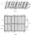
FIG. 1 is a schematic three-dimensional structural diagram of a battery pack according to an embodiment of this application. -
FIG. 2 is a vertical view of the battery pack shown inFIG. 1 with a box cover omitted. -
FIG. 3 is a schematic three-dimensional structural diagram ofFIG. 2 with thermal insulation glue omitted. -
FIG. 4 is a vertical view ofFIG. 3 with a protective member omitted. -
FIG. 5 is a schematic three-dimensional structural diagram of the protective member inFIG. 3 . -
FIG. 6 is a vertical view ofFIG. 1 . -
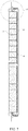
FIG. 7 is a cross-sectional view ofFIG. 6 in A-A direction. -
FIG. 8 is a partial enlarged schematic diagram of part I inFIG. 7 . - In which:
- 100. battery pack;
- 1. accommodating box; 11. box body; 111. cavity; 111a. inner wall; 112. side part; 113. convex part; 114. bottom part; 12. box cover; 121. top plate; 122. side plate; 123. flange part; 1a. accommodating zone; 13. explosion-proof exhaust structure;
- 2. thermal insulation glue;
- 3. partitioning structure; 31. first partitioner; 32. second partitioner;
- 4. battery module; 41. battery row; 41a. first battery row; 41b. second battery row; 411. battery; 411a. top cover; 411b. explosion-proof valve; 42. protective member; 421. main body plate; 422. bent plate;
- 5. constraining component;
- P1. first path; P2. second path; B. gap; H. height direction; W. first direction; and L. second direction.
- The following clearly and completely describes the technical solutions in the embodiments of this application with reference to the accompanying drawings in the embodiments of this application. Apparently, the described embodiments are only some rather than all of the embodiments of this application. The following description of at least one example embodiment is merely illustrative and definitely is not construed as any limitation on this application or on use of this application. All other embodiments obtained by a person of ordinary skill in the art based on the embodiments of this application without creative efforts shall fall within the protection scope of this application.
- The technologies, methods, and devices known to those of ordinary skill in the related art may not be discussed in detail, but where appropriate, the technologies, methods, and devices should be regarded as being authorized as a part of the specification.
- In the description of this application, it should be understood that the use of words "first", "second" and the like to define parts is merely intended to distinguish between the respective parts, and unless otherwise specified, the words have no special meaning and therefore are not construed as any limitation on the protection scope of this application.
- In addition, technical features in different embodiments of this application described below can be combined with each other as long as they do not conflict with each other.
-
FIG. 1 to FIG. 6 show a battery pack according to an embodiment of this application. In the illustrated embodiment, thebattery pack 100 is used as a power apparatus of a vehicle, disposed in a vehicle body, and configured to provide electric power for the vehicle. In some embodiments, the vehicle may include: a traction source that provides traction for the vehicle, and a battery pack according to some embodiments, where the battery pack is configured to supply power to the traction source, so as to provide electric power for the vehicle. The vehicle may include an electric vehicle, a hybrid electric vehicle, or the like. The electric vehicle may use an electric engine powered by electric energy output from the battery pack as the traction source, and the electric vehicle may use the battery pack according to some embodiments to power the electric engine, for example, a main traction source and/or a backup traction source. The hybrid electric vehicle may use two or more types of traction sources, for example, internal combustion engines and electric motors, to provide traction. - To clearly describe the orientations below, directions of the
battery pack 100 are defined by using a coordinate system inFIG. 1 . The coordinate axis H represents a height direction of thebattery pack 100 and is also a height direction of an accommodating box 1 and abattery 411 in the accommodating box 1; the coordinate axis W is perpendicular to the coordinate axis H and referred to as a first direction, and represents a width direction of the battery pack; and the coordinate axis L is perpendicular to the coordinate axis H and the coordinate axis W and referred to as a second direction, and represents a length direction of the battery pack. - Based on the foregoing orientation definitions, the terms "over", "under", "top", "bottom", and the like used in the following descriptions to indicate the orientation or position relationship are all relative to the height direction H. A
box cover 12 and abox body 11 of the battery pack are disposed oppositely in the height direction H, thebox cover 12 is over thebox body 11, and thebox body 11 is under thebox cover 12. - However, it should be understood that, the foregoing orientation definitions are merely intended to simplify the descriptions of this application for a purpose of easy description. Unless otherwise stated, these orientation words do not indicate or imply that an apparatus or an element must have a particular orientation or must be constructed and operated in a particular orientation. Therefore, this shall not be construed as any limitation on the protection scope of this application.
- As shown in
FIG. 1 to FIG. 8 , thebattery pack 100 of this embodiment includes an accommodating box 1 and abattery module 4. - The accommodating box 1 is configured to accommodate the
battery module 4 to provide protection for thebattery module 4 inside the accommodating box 1. As shown inFIG. 1 to FIG. 3 , in this embodiment, the accommodating box 1 includes abox body 11 and abox cover 12. Acavity 111 is provided inside thebox body 11 for accommodating thebattery module 4 and the like, where a top of thecavity 111 is open to facilitate insertion or removal of thebattery module 4, and thebox cover 12 is closed on a top of thebox body 11 to seal thecavity 111. Thebox cover 12 is adapted to thebox body 11 in a sealed manner. For example, a sealing ring or other sealing elements may be provided between thebox cover 12 and thebox body 11. - It can be learned from
FIG. 3 that thebox body 11 includes abottom part 114, aside part 112, and aconvex part 113. Theside part 112 and thebottom part 114 enclose thecavity 111, theside part 112 is connected to the periphery of thebottom part 114 and extends upward, and theconvex part 113 is connected to one end of theside part 112 and extends outward in a second direction L. Specifically, theside part 112 and thebottom part 114 enclose a hollow cuboid, and the innercuboid cavity 111 is configured to accommodate thebattery module 4. Theconvex part 113 is trapezoid, and electronic components may be arranged on theconvex part 113 to control working modes such as charging and discharging of thebattery module 4. - It can be learned from
FIG. 1 andFIG. 6 that thebox cover 12 is adapted to thebox body 11 in overall shape, and includes a rectangular part and a trapezoidal part. The rectangular part includes atop plate 121 and aside plate 122 connected to the periphery of thetop plate 121 and extending downward. The trapezoidal part is connected to one end of theside plate 122 and extends outward in the second direction L to form aflange part 123. - When the
box cover 12 is closed on thebox body 11, theside plate 122 of thebox cover 12 mates with theside part 112 of thebox body 11, and theflange part 123 of thebox cover 12 mates with to theconvex part 113 of thebox body 11, so as to seal thecavity 111. - When the accommodating box 1 is disposed on a vehicle body, the
box cover 12 faces upwards, and a side on which theconvex part 113 and theflange part 123 are located is disposed close to the front of the vehicle. In other words, when thebattery pack 100 is installed on the vehicle, the height direction H is a height direction of the vehicle body, and the second direction L is a length direction of the vehicle body, which is also a direction in which the vehicle travels. - The
battery module 4 is disposed in thecavity 111 and is a core component of thebattery pack 100 for providing electric energy for the vehicle. As shown inFIG. 3 to FIG. 8 , in this embodiment, thebattery module 4 includes abattery row 41 and aprotective member 42. - The
battery row 41 includes a plurality ofbatteries 411, where thebattery 411 includes atop cover 411a and an explosion-proof valve 411b disposed on thetop cover 411a. When thebattery 411 is experiencing thermal runaway, the explosion-proof valve 411b may be forced to open by gas, heat, flames, and high-temperature and high-pressure fluid (collectively referred to as produced gas) produced inside thebattery 411, and the produced gas is discharged out of thebattery 411, so that pressure inside thebattery 411 is released from thetop cover 411a. - All the
batteries 411 in thebattery row 41 are arranged side by side along the same direction. InFIG. 3 , all thebatteries 411 in thebattery row 41 are arranged vertically, the height direction H is the vertical direction and is consistent with the height direction of thebox body 11, and thetop covers 411a all face upwards, in other words, thetop covers 411a all face toward thebox cover 12 and face away from thebox body 11. In addition, all thebatteries 411 in thebattery row 41 are arranged side by side along the first direction W to form a row. - The
protective member 42 covers all explosion-proof valves 411b of thebattery row 41, and a first path P1 for guiding airflow to flow in the first direction W is provided between theprotective member 42 and an upper surface of thetop cover 411a. Based on this, theprotective member 42 can protect thebattery row 41 and control a diffusion range of the produced gas, so that the produced gas discharged from the explosion-proof valve 411b on thetop cover 411a can be guided by theprotective member 42 along the first path P1 to flow to two sides of thebattery pack 100 in the first direction W, instead of being directly sprayed upwards. This not only can guide the produced gas to discharge from the two sides of thebattery pack 100 in the first direction W, reduce accumulation of the produced gas inside thebattery pack 100, and improve use safety of thebattery pack 100, but also can prevent the produced gas from directly impacting a passenger above thebattery pack 100, thereby improving the safety performance of the vehicle. - Specifically, as shown in
FIG. 5 , theprotective member 42 includes amain body plate 421 and twobent plates 422. Themain body plate 421 extends in the first direction W. The twobent plates 422 are connected to opposite ends of themain body plate 421 in the second direction L respectively, and are both bent downward relative to the main body plate 421 (that is, toward the direction close to the battery row 4). Based on this, the twobent plates 422 support themain body plate 421 over thebattery row 4, and themain body plate 421, the twobent plates 422, and the upper surface of thetop cover 411a form the first path P1 extending in the first direction W. A top of the first path P1 and two ends of the first path P1 in the second direction L are all closed, and only two ends of the first path P1 in the first direction W are open, so that under the action of theprotective member 42, the produced gas rushing out from the explosion-proof valve 411b of thebattery 411 cannot flow upwards any more, but flows out in the first direction W. When the batteries are installed on the vehicle body, the first direction W is the width direction of the vehicle body, instead of the direction in which the front of the vehicle or a passenger is located. Therefore, guiding the produced gas to be discharged in the width direction of the vehicle body can safely discharge the produced gas and reduce threat of the produced gas to safety of the passenger. - The
main body plate 421 and thebent plates 422 may be in various plate structures such as flat plates, curved plates, or specially shaped plates, and theprotective member 42 may have a cross section (that is, a section perpendicular to the first direction W) of various shapes such as an inverted U shape or M shape. For example, inFIG. 3 , theprotective member 42 has an inverted U-shaped cross section. Compared with other shapes, theprotective member 42 has a simpler structure, so as to facilitate processing. - To limit the
protective member 42 conveniently, theprotective member 42 may be connected to thebox cover 12, for example, may be welded to thetop plate 121 through themain body plate 421, to install and fix theprotective member 42 and help theprotective member 42 more reliably cover the all explosion-proof valves 411b of thebattery row 41. Compared with theprotective member 42 having an M-shaped cross section and other shapes, for theprotective member 42 having an inverted U-shaped cross section, themain body plate 421 of theprotective member 42 and thetop plate 121 can be in closer contact with each other based on a larger area, thereby facilitating stronger welding between theprotective member 42 and thetop plate 121. - As shown in
FIG. 3 , in this embodiment, thebattery module 4 is provided with sixbattery rows 41, and the sixbattery rows 41 are arranged side by side along the second direction L. In addition, thebattery module 4 includes sixprotective members 42, and theprotective members 42 are all arranged in a one-to-one correspondence with thebattery rows 41, so that eachprotective member 42 can be used to guide the produced gas released by explosion-proof valves 411b of acorresponding battery row 41 to be discharged in the first direction W. - In a variant embodiment, the number of
battery rows 41 in thebattery module 4 may alternatively be one or two. In other words, thebattery module 4 may include one or at least twobattery rows 41. When thebattery module 4 includes at least twobattery rows 41, thebattery rows 41 are all arranged side by side along the second direction L, and in this case, theprotective members 42 in thebattery module 4 have the same quantity as thebattery rows 41 and are arranged above thebattery rows 41 in a one-to-one correspondence. - As set forth, the
battery pack 100 of this embodiment includes a plurality ofbattery rows 41, and the number ofbatteries 411 in eachbattery row 41 is more than one. Therefore, thebattery pack 100 has a plurality ofbatteries 411, and the plurality ofbatteries 411 are arranged in rows and columns to form a multi-row and multi-column battery array. - For more orderly placement of the plurality of
batteries 411 in thebattery pack 100, as shown inFIG. 2 andFIG. 3 , thebattery pack 100 may further include apartitioning structure 3, where thepartitioning structure 3 is disposed in thecavity 111 and partitions thecavity 111 into at least twoaccommodating zones 1a, and thebatteries 411 in thebattery pack 100 are grouped and arranged in differentaccommodating zones 1a. In this way, different groups ofbatteries 411 are respectively accommodated in differentaccommodating zones 1a, which makes the placement more orderly and convenient, and in addition, the different groups ofbatteries 411 can be more reliably limited by thepartitioning structure 3. - It can be learned from
FIG. 3 that thepartitioning structure 3 of this embodiment includes afirst partitioner 31, where thefirst partitioner 31 extends in the first direction W, and partitions thecavity 111 into differentaccommodating zones 1a arranged in the second direction L; and thepartitioning structure 3 further includes asecond partitioner 32, where thesecond partitioner 32 extends in the second direction L, and intersects with thefirst partitioner 31. In this way, thesecond partitioner 32 further partitions theaccommodating zones 1a partitioned by thefirst partitioner 31, so that there are moreaccommodating zones 1a in thecavity 111. Theseaccommodating zones 1a not only includeaccommodating zones 1a arranged in the second direction L, but also includeaccommodating zones 1a arranged in the first direction W. - When the
batteries 411 are grouped and placed in thecavity 111,different battery rows 41 may be grouped and accommodated in differentaccommodating zones 1a arranged in the second direction L, so as to realize partition placement of different groups ofbattery rows 41, andbatteries 411 in thesame battery row 41 are grouped and accommodated in the first direction W in differentaccommodating zones 1a arranged in the first direction W, so as to realize the partition placement within thesame battery row 41 in the first direction W. - Specifically, in the illustrated embodiment, it can be learned from
FIG. 3 that thepartitioning structure 3 includes twofirst partitioners 31 and onesecond partitioner 32, and the twofirst partitioners 31 are apart from each other and arranged side by side along the second direction L, and thesecond partitioner 32 is perpendicular to both of the twofirst partitioners 31. In this way, under the action of the first partitioners 31 and thesecond partitioner 32, thepartitioning structure 3 partitions thecavity 111 into 2 rows and 3 columns, that is, a total of sixaccommodating zones 1a. The sixbattery rows 41 arranged side by side along the second direction L are partitioned by the twofirst partitioners 31, where twobattery rows 41 are located on the same side of the samefirst partitioner 31, and onebattery row 41 is further partitioned by thesecond partitioner 32 in the first direction W, so that eachbattery row 41 is partitioned by thesecond partitioner 32 into afirst battery row 41a and a second battery row 41b that are arranged in the first direction W, and thefirst battery row 41a and the second battery row 41b in thesame battery row 41 are also in differentaccommodating zones 1a. - More specifically, as shown in
FIG. 3 , in this embodiment, thesecond partitioner 32 is located in the middle of thebattery row 41 in the first direction W, so that the number ofbatteries 411 in thefirst battery row 41a is equal to the number ofbatteries 411 in the second battery row 41b. - It should be understood that the number of
first partitioners 31, the number ofsecond partitioners 32, and a position of thefirst partitioner 31 are not limited to those shown inFIG. 3 . For example, the number ofsecond partitioners 32 may alternatively be at least two. For another example, the number offirst partitioners 31 may alternatively vary with the number ofbattery rows 41, generally one less than the number ofbattery rows 41. When the number offirst partitioners 31 is at least two, thefirst partitioners 31 are spaced apart from each other and arranged side by side along the second direction L. For another example, thesecond partitioner 32 may not be located in the middle of thebattery row 41 in the first direction W, but may be located close to one side in the first direction W. In this case, the number ofbatteries 411 in thefirst battery row 41a is not equal to the number ofbatteries 411 in the second battery row 41b any more. - The
first partitioner 31 and thesecond partitioner 32 may be constructed as a beam structure. InFIG. 3 , thefirst partitioner 31 may be referred to as a transverse beam, and thesecond partitioner 32 may be referred to as a longitudinal beam. In addition, thefirst partitioner 31 and thesecond partitioner 32 are both fixedly connected to thebox body 11. Specifically, thefirst partitioner 31 and thesecond partitioner 32 are both fixedly connected to thebottom part 114 of thebox body 11. - To more reliably constrain the
batteries 411 in thebattery pack 100, as shown inFIG. 2 to FIG. 6 , in this embodiment, thebattery pack 100 further includes a constrainingcomponent 5, where the constrainingcomponent 5 is disposed in thecavity 111, located between thebattery row 41 and aninner wall 111a of thecavity 111 in the first direction W, and configured to constrain thebattery row 41. By disposing the constrainingcomponent 5, the displacement of thebattery row 41 in the first direction W can be constrained, especially a swelling force experienced by thebattery row 41 can be resisted, so that swelling and deformation of thebattery row 41 can be reduced. - The constraining
component 5 may be connected to thefirst partitioner 31 to, for example, fix the constrainingcomponent 5. - The constraining
component 5 may extend from one end to the other end of thecavity 111a in the second direction L, for example, may be configured as a beam structure or a plate structure extending in the second direction L, so that the constrainingcomponent 5 can constrain allbattery rows 41 in thebattery module 4 that are arranged in the second direction L, to limit all thebattery rows 41. In this way, there is no need to separately provide the constrainingcomponent 5 for eachbattery row 41, thereby effectively reducing the number of constrainingcomponents 5, simplifying the overall structure of thebattery pack 100, and facilitating installation of thebattery module 4 in the accommodating box 1. - The constraining
component 5 may be provided only on one side of thebattery row 41 in the first direction W. However, in this embodiment, the constrainingcomponent 5 is provided on two opposite sides of thebattery row 41 in the first direction W, to be specific, thebattery pack 100 includes two constrainingcomponents 5 respectively arranged on two opposite sides of thebattery row 41 in the first direction W, so that the two constrainingcomponents 5 can be used to clamp thebattery row 41 in the middle to achieve a more reliable limitation effect. - To further facilitate the discharge of the produced gas, as shown in
FIG. 7 andFIG. 8 , in this embodiment, in the height direction H, the two constrainingcomponents 5 are both disposed with their tops lower than the upper surface of thetop cover 411a, so that the tops of the constrainingcomponents 5, thebattery row 41, and thebox cover 12 form a second path P2 communicating with the first path P1. As a result, the produced gas flowing out of the first path P1 can be more smoothly discharged to two sides of thebattery pack 100 in the first direction W under the guidance of the second path P2, and the high-temperature and high-pressure fluid produced inside thebattery 411 is released promptly when thebattery 411 experiences thermal runaway, preventing heat spread and reducing safety risks. In addition, compared with other methods of forming the second path P2, for example, providing a recessed groove in the first direction W on the surface of the constrainingcomponent 5, forming the second path P2 is simpler in both structure and process by making the tops of the constrainingcomponents 5 lower than the upper surface of thetop cover 411a. - In some variant embodiments, for the two constraining
components 5, instead of disposing the entire top being lower than the upper surface of thetop cover 411a, only a part of the top is lower than the upper surface of thetop cover 411a. In this case, a part of a top of the constrainingcomponent 5 lower than the upper surface of thetop cover 411a, thebattery row 41, and thebox cover 12 can still form the second path P2. However, a size of the second path P2 in the second direction L is smaller than that of the illustrated embodiment. - In some other variant embodiments, at least a part of a top of only one of the two constraining
components 5 may alternatively be lower than the upper surface of thetop cover 411a. In this case, the second path P2 is formed only on one side of thebattery row 41 in the first direction W. - Under the directional guidance of the first path P1 and the second path P2, the produced gas rushing out from the inside of the
battery 411 can more smoothly flow in the first direction W to two sides of the accommodating box 1 in the first direction W, and then is discharged on the two sides of the accommodating box 1 in the first direction W. - To further facilitate the discharge of the produced gas flowing out of the second path P2 out of the accommodating box 1, as shown in
FIG. 1 andFIG. 6 , in this embodiment, an explosion-proof exhaust structure 13 is provided on theside plate 122 of thebox cover 12 that is opposite the second path P2, and the explosion-proof exhaust structure 13 communicates with the second path P2 and is configured to discharge the fluid in the second path P2 out of thebattery pack 100. The explosion-proof exhaust structure 13 may include an explosion-proof valve 411b; or the explosion-proof exhaust structure 13 may include a weak part, where the weak part is a part of theside plate 122, and the weak part has lower strength than other parts of theside plate 122. The weak part may be, for example, a groove or an indentation in theside plate 122. - The explosion-
proof exhaust structure 13 is disposed on theside plates 122 at two ends of thebox cover 12 in the first direction W, so that the produced gas guided by the second path P2 can be easily discharged through the explosion-proof exhaust structure 13, with smoother exhaust achieved. In addition, the explosion-proof exhaust structure 13 can control the discharge of the produced gas to some extent, for example, can control the produced gas to be discharged when a preset pressure is reached, helping to further improve the use safety of thebattery pack 100. - It can be learned from
FIG. 6 that in the constrainingcomponent 5 of this embodiment, the top of the constrainingcomponent 5 is lower than the upper surface of thetop cover 411a, and at least a part of the constrainingcomponent 5 is also made to be lower than the bottom of the explosion-proof exhaust structure 13, so that the constrainingcomponent 5 can avoid the explosion-proof exhaust structure 13, which is beneficial to keeping the explosion-proof exhaust structure 13 unobstructed and is more convenient for the produced gas to be discharged through the explosion-proof exhaust structure 13. - In addition, as shown in
FIG. 2 , in this embodiment, a space between the upper surface of thetop cover 411a and thetop plate 121, except for the part corresponding to theprotective member 42, is filled with thethermal insulation glue 2. Based on this, in the entire height direction H, the space between thetop plate 121 and the upper surface of thebattery row 41, except for a zone corresponding to theprotective member 42, is filled by and sealed with thethermal insulation glue 2, helping to further improve the safety performance of thebattery pack 100. If the space between thetop plate 121 and the upper surface of thebattery row 41 outside theprotective member 42 is not sealed, the produced gas guided by the first path P1 to two sides of thebattery row 41 in the first direction W may flow back to the space between thetop plate 121 and the upper surface of thetop cover 411a outside theprotective member 42, which poses threat to the use safety of thebattery pack 100. In this embodiment, the space between thetop plate 121 and the upper surface of thetop cover 411a outside theprotective member 42 is sealed by using thethermal insulation glue 2. This can effectively prevent the produced gas guided by the first path P1 from flowing back to the top of thebattery row 41, and help the produced gas guided by the first path P1 to more fully flow to the second path P2, thereby helping improve the safety performance of thebattery pack 100. In addition, thebattery rows 41 arranged in the second direction L can also be separated due to thermal insulation performance of thethermal insulation glue 2, to prevent abattery row 41 that has already experienced thermal runaway from causingother battery rows 41 to also experience thermal runaway. From such point of view, the provision of thethermal insulation glue 2 also helps to improve the safety performance of thebattery pack 100. - In conclusion, in this application, the first path P1 and the second path P2 can more effectively and more reliably guide the produced gas to be discharged to the explosion-
proof exhaust structure 13 in the desired first direction W, and promptly release the high-temperature and high-pressure fluid produced inside thebattery 411 when thebattery 411 experiences thermal runaway, preventing the produced gas from spreading in the accommodating box 1, reducing the risk of thermal runaway, improving use safety of thebattery pack 100, and reducing safety risks of passengers in a vehicle to which thebattery pack 100 is applied. - The foregoing descriptions are merely example embodiments of this application, but are not intended to limit this application. Any modification, equivalent replacement, or improvement made without departing from the spirit and principle of this application shall fall within the protection scope of this application.
Claims (10)
- A battery pack (100), comprising:an accommodating box (1), comprising a box body (11) and a box cover (12), wherein a cavity (111) is provided inside the box body (11), and the box cover (12) is closed on a top of the box body (11);a battery row (41), comprising a plurality of batteries (411) arranged side by side in the cavity (111) along a first direction (W), wherein a battery (411) comprises a top cover (411a) and an explosion-proof valve (411b) disposed on the top cover (411a);a protective member (42), covering all explosion-proof valves (411b) of the battery row (41), wherein a first path (PI) for guiding fluid to flow in the first direction (W) is provided between the protective member (42) and an upper surface of the top cover (411a), and the first direction (W) is perpendicular to a height direction (H) of the battery (411); anda constraining component (5), disposed in the cavity (111), located between the battery row (41) and an inner wall (111a) of the cavity (111) in the first direction (W), and configured to constrain the battery row (41);wherein in the height direction (H), at least a part of a top of the constraining component (5) is lower than the upper surface of the top cover (411a), and the part of the top of the constraining component (5) lower than the upper surface of the top cover (411a), the battery row (41), and the box cover (12) form a second path (P2) communicating with the first path (PI).
- The battery pack (100) according to claim 1, wherein the battery pack (100) comprises at least two battery rows (41) and at least two protective members (42), the at least two battery rows (41) are arranged side by side along a second direction (L), the at least two protective members (42) are in one-to-one correspondence with the at least two battery rows (41), the constraining component (5) constrains the at least two battery rows (41), and the second direction (L) is perpendicular to the first direction (W) and the height direction (H).
- The battery pack (100) according to claim 1 or 2, wherein the battery pack (100) comprises two constraining components (5), and the two constraining components (5) are respectively located at two sides of the battery row (41) that are opposite in the first direction (W).
- The battery pack (100) according to any one of claims 1 to 3, wherein an explosion-proof exhaust structure (13) is provided on a side plate (122) of the box cover (12) that is opposite the second path (P2), and the explosion-proof exhaust structure (13) communicates with the second path (P2) and is configured to discharge the fluid in the second path (P2) out of the battery pack (100).
- The battery pack (100) according to claim 4, wherein the explosion-proof exhaust structure (13) comprises an explosion-proof valve or a weak part, the weak part is a part of the side plate (122), and the weak part has lower strength than other parts of the side plate (122).
- The battery pack (100) according to any one of claims 1 to 5, wherein the battery pack (100) further comprises a partitioning structure (3), the partitioning structure (3) is disposed in the cavity (111) and partitions the cavity (111) into at least two accommodating zones (1a), the batteries (411) in the battery pack (100) are grouped and arranged in different accommodating zones (1a), the partitioning structure (3) comprises a first partitioner (31), the first partitioner (31) extends in the first direction (W), and the constraining component (5) is connected to the first partitioner (31).
- The battery pack (100) according to claim 6, wherein the partitioning structure (3) further comprises a second partitioner (32), the second partitioner (32) intersects with the first partitioner (31), and the second partitioner (32) and the first partitioner (31) jointly partition the cavity (111) into the at least two accommodating zones (1a).
- The battery pack (100) according to any one of claims 1 to 7, wherein a space between the upper surface of the top cover (411a) and a top plate (121) of the box cover (12) and outside the first path (PI) is filled with thermal insulation glue (2).
- The battery pack (100) according to any one of claims 1 to 8, wherein the protective member (42) has an inverted U-shaped cross section.
- A vehicle, comprising:a traction source, wherein the traction source provides traction for the vehicle; andthe battery pack (100) according to any one of claims 1 to 9, wherein the battery pack (100) is configured to supply power to the traction source.
Applications Claiming Priority (2)
| Application Number | Priority Date | Filing Date | Title |
|---|---|---|---|
| CN201910975581.3A CN112331997B (en) | 2019-10-15 | 2019-10-15 | Battery packs and vehicles |
| PCT/CN2020/117309 WO2021073387A1 (en) | 2019-10-15 | 2020-09-24 | Battery pack and vehicle |
Publications (3)
| Publication Number | Publication Date |
|---|---|
| EP3930027A1 true EP3930027A1 (en) | 2021-12-29 |
| EP3930027A4 EP3930027A4 (en) | 2022-10-26 |
| EP3930027B1 EP3930027B1 (en) | 2025-12-24 |
Family
ID=74319244
Family Applications (1)
| Application Number | Title | Priority Date | Filing Date |
|---|---|---|---|
| EP20876475.3A Active EP3930027B1 (en) | 2019-10-15 | 2020-09-24 | Battery pack and vehicle |
Country Status (7)
| Country | Link |
|---|---|
| US (1) | US12431583B2 (en) |
| EP (1) | EP3930027B1 (en) |
| JP (1) | JP7513710B2 (en) |
| KR (1) | KR102657880B1 (en) |
| CN (1) | CN112331997B (en) |
| ES (1) | ES3063915T3 (en) |
| WO (1) | WO2021073387A1 (en) |
Cited By (10)
| Publication number | Priority date | Publication date | Assignee | Title |
|---|---|---|---|---|
| EP4312305A1 (en) * | 2022-07-28 | 2024-01-31 | Xiaomi EV Technology Co., Ltd. | Battery pack, method for manufacturing battery pack, and vehicle |
| US12230826B2 (en) | 2022-03-23 | 2025-02-18 | Ford Global Technologies, Llc | Methods for assembling traction battery packs |
| US12275298B2 (en) | 2022-03-23 | 2025-04-15 | Ford Global Technologies, Llc | Traction battery packs with cell-to-pack battery systems housed within irregularly shaped enclosures |
| US12374750B2 (en) | 2022-03-23 | 2025-07-29 | Ford Global Technologies, Llc | Traction battery pack assembling method |
| US12424695B2 (en) | 2022-03-23 | 2025-09-23 | Ford Global Technologies, Llc | Retention assemblies for traction battery packs with cell-to-pack battery systems |
| US12479327B2 (en) | 2022-03-23 | 2025-11-25 | Ford Global Technologies, Llc | Traction battery pack cell stack removal method and battery pack assembly |
| US12506215B2 (en) | 2022-03-23 | 2025-12-23 | Ford Global Technologies, Llc | Enclosure cover attachment configurations for traction battery packs with cell-to-pack battery systems |
| US12525637B2 (en) | 2022-03-23 | 2026-01-13 | Ford Global Technologies, Llc | Traction battery pack assembling method |
| US12567642B2 (en) | 2022-03-23 | 2026-03-03 | Ford Global Technologies, Llc | Shim systems for traction battery packs |
| US12603373B2 (en) | 2022-03-23 | 2026-04-14 | Ford Global Technologies, Llc | Traction battery pack assembling method |
Families Citing this family (11)
| Publication number | Priority date | Publication date | Assignee | Title |
|---|---|---|---|---|
| US11764431B2 (en) | 2020-10-22 | 2023-09-19 | Apple Inc. | Battery pack structures and systems |
| CN112787020B (en) * | 2021-03-11 | 2025-04-25 | 蔚来汽车科技(安徽)有限公司 | Power battery pack with thermal insulation component |
| US12283712B2 (en) * | 2021-12-27 | 2025-04-22 | Lg Energy Solution, Ltd. | Battery pack and vehicle including the same |
| US12594823B2 (en) * | 2022-02-24 | 2026-04-07 | Mazda Motor Corporation | Vehicle-body front structure with side frame support |
| WO2024063981A1 (en) * | 2022-09-23 | 2024-03-28 | Apple Inc. | Structural battery pack with durability improvements |
| EP4478502A4 (en) * | 2022-10-14 | 2025-07-30 | Contemporary Amperex Technology Hong Kong Ltd | BATTERY AND ELECTRICAL DEVICE |
| CN115498348B (en) * | 2022-11-18 | 2023-03-14 | 中创新航科技股份有限公司 | Battery pack assembling method and assembling equipment and battery pack |
| FR3150047A1 (en) * | 2023-06-15 | 2024-12-20 | Valeo Systemes Thermiques | thermal regulation device of a vehicle battery pack |
| CN220796940U (en) * | 2023-07-26 | 2024-04-16 | 比亚迪股份有限公司 | Battery trays, battery packs and vehicles |
| CN118380704A (en) * | 2024-05-23 | 2024-07-23 | 上海兰钧新能源科技有限公司 | Battery pack, battery manufacturing method and mold |
| JP2025187417A (en) * | 2024-06-13 | 2025-12-25 | トヨタ自動車株式会社 | Power storage device |
Family Cites Families (17)
| Publication number | Priority date | Publication date | Assignee | Title |
|---|---|---|---|---|
| JP2008243672A (en) | 2007-03-28 | 2008-10-09 | Toshiba Corp | Secondary electrode for rechargeable battery, lithium ion rechargeable battery and rechargeable battery pack |
| EP2325922B1 (en) | 2009-11-19 | 2012-05-09 | SB LiMotive Co., Ltd. | Battery pack |
| US9083029B2 (en) * | 2009-12-23 | 2015-07-14 | Samsung Sdi Co., Ltd. | Battery pack |
| JP5341156B2 (en) | 2011-09-06 | 2013-11-13 | 三洋電機株式会社 | Power supply |
| KR101282473B1 (en) * | 2011-09-21 | 2013-07-04 | 로베르트 보쉬 게엠베하 | Battery pack |
| JP2013171746A (en) * | 2012-02-21 | 2013-09-02 | Sanyo Electric Co Ltd | Power supply device, and vehicle and power storage device having the same |
| KR101881196B1 (en) | 2015-06-16 | 2018-07-23 | 주식회사 엘지화학 | Battery Pack |
| JP6606907B2 (en) | 2015-07-30 | 2019-11-20 | 株式会社Gsユアサ | Power storage device |
| JP2017098014A (en) * | 2015-11-20 | 2017-06-01 | 三菱自動車工業株式会社 | Battery module |
| CN108075062B (en) * | 2016-11-09 | 2021-08-06 | Cps科技控股有限公司 | Battery pack with two end plates |
| CN209183604U (en) * | 2018-12-27 | 2019-07-30 | 宁德时代新能源科技股份有限公司 | battery box |
| CN109742281B (en) | 2018-12-27 | 2021-05-28 | 宁德时代新能源科技股份有限公司 | a battery box |
| CN209104229U (en) * | 2018-12-27 | 2019-07-12 | 宁德时代新能源科技股份有限公司 | battery box |
| CN110190212B (en) | 2018-12-29 | 2020-02-04 | 比亚迪股份有限公司 | Power battery pack and vehicle |
| CN209401710U (en) * | 2019-03-28 | 2019-09-17 | 宁德时代新能源科技股份有限公司 | Battery modules and battery packs |
| CN210182427U (en) * | 2019-04-16 | 2020-03-24 | 上海申传电气股份有限公司 | Cast-in explosion-proof structure of lithium battery power supply |
| WO2021097644A1 (en) * | 2019-11-19 | 2021-05-27 | 宁德时代新能源科技股份有限公司 | Battery pack and transport equipment |
-
2019
- 2019-10-15 CN CN201910975581.3A patent/CN112331997B/en active Active
-
2020
- 2020-09-24 JP JP2022523012A patent/JP7513710B2/en active Active
- 2020-09-24 EP EP20876475.3A patent/EP3930027B1/en active Active
- 2020-09-24 WO PCT/CN2020/117309 patent/WO2021073387A1/en not_active Ceased
- 2020-09-24 KR KR1020227012577A patent/KR102657880B1/en active Active
- 2020-09-24 ES ES20876475T patent/ES3063915T3/en active Active
-
2021
- 2021-10-26 US US17/511,277 patent/US12431583B2/en active Active
Cited By (11)
| Publication number | Priority date | Publication date | Assignee | Title |
|---|---|---|---|---|
| US12230826B2 (en) | 2022-03-23 | 2025-02-18 | Ford Global Technologies, Llc | Methods for assembling traction battery packs |
| US12275298B2 (en) | 2022-03-23 | 2025-04-15 | Ford Global Technologies, Llc | Traction battery packs with cell-to-pack battery systems housed within irregularly shaped enclosures |
| US12374750B2 (en) | 2022-03-23 | 2025-07-29 | Ford Global Technologies, Llc | Traction battery pack assembling method |
| US12424695B2 (en) | 2022-03-23 | 2025-09-23 | Ford Global Technologies, Llc | Retention assemblies for traction battery packs with cell-to-pack battery systems |
| US12479327B2 (en) | 2022-03-23 | 2025-11-25 | Ford Global Technologies, Llc | Traction battery pack cell stack removal method and battery pack assembly |
| US12506215B2 (en) | 2022-03-23 | 2025-12-23 | Ford Global Technologies, Llc | Enclosure cover attachment configurations for traction battery packs with cell-to-pack battery systems |
| US12525637B2 (en) | 2022-03-23 | 2026-01-13 | Ford Global Technologies, Llc | Traction battery pack assembling method |
| US12567642B2 (en) | 2022-03-23 | 2026-03-03 | Ford Global Technologies, Llc | Shim systems for traction battery packs |
| US12603373B2 (en) | 2022-03-23 | 2026-04-14 | Ford Global Technologies, Llc | Traction battery pack assembling method |
| EP4312305A1 (en) * | 2022-07-28 | 2024-01-31 | Xiaomi EV Technology Co., Ltd. | Battery pack, method for manufacturing battery pack, and vehicle |
| US12573710B2 (en) | 2022-07-28 | 2026-03-10 | Xiaomi Ev Technology Co., Ltd. | Battery pack, method for manufacturing battery pack, and vehicle |
Also Published As
| Publication number | Publication date |
|---|---|
| JP7513710B2 (en) | 2024-07-09 |
| CN112331997B (en) | 2021-11-12 |
| US12431583B2 (en) | 2025-09-30 |
| KR20220065808A (en) | 2022-05-20 |
| EP3930027B1 (en) | 2025-12-24 |
| CN112331997A (en) | 2021-02-05 |
| ES3063915T3 (en) | 2026-04-21 |
| KR102657880B1 (en) | 2024-04-15 |
| US20220052415A1 (en) | 2022-02-17 |
| WO2021073387A1 (en) | 2021-04-22 |
| JP2022553242A (en) | 2022-12-22 |
| EP3930027A4 (en) | 2022-10-26 |
Similar Documents
| Publication | Publication Date | Title |
|---|---|---|
| US12431583B2 (en) | Battery pack and vehicle | |
| CN112331981B (en) | Battery pack and vehicle | |
| US11949114B2 (en) | Battery box | |
| EP3926747A1 (en) | Battery pack and apparatus | |
| KR102665192B1 (en) | Battery pack and device including the same | |
| CN111668409A (en) | Battery trays, power battery packs and vehicles | |
| KR102926488B1 (en) | Battery pack with gas venting path | |
| CN219350557U (en) | Battery tray and battery pack | |
| CN111668423A (en) | Battery modules, power battery packs and vehicles | |
| WO2024109418A1 (en) | Battery pack and automobile | |
| CN220544136U (en) | Battery pack trays, battery packs and vehicles | |
| CN110854466B (en) | Interval interactive microchannel liquid cooling plate | |
| CN223898515U (en) | Explosion-proof valve assembly, battery pack and electric equipment | |
| JP7780475B2 (en) | Battery pack | |
| EP4668430A1 (en) | Power battery system and its power battery module | |
| CN223598950U (en) | Battery pack and electricity utilization device | |
| CN223066390U (en) | Protective structure for battery, battery pack and electric equipment | |
| WO2026001007A1 (en) | Venting member, battery tray, battery pack, and electrical device | |
| EP4270604A1 (en) | Battery pack having improved cooling performance and vehicle including same | |
| KR20260015560A (en) | Battery Module And Battery Pack Including The Same | |
| JP2023174806A (en) | battery pack | |
| WO2025251424A1 (en) | Battery pack and electric device | |
| KR20260063428A (en) | Battery pack | |
| KR20260056641A (en) | Cooling structure and battery device having the same |
Legal Events
| Date | Code | Title | Description |
|---|---|---|---|
| STAA | Information on the status of an ep patent application or granted ep patent |
Free format text: STATUS: THE INTERNATIONAL PUBLICATION HAS BEEN MADE |
|
| PUAI | Public reference made under article 153(3) epc to a published international application that has entered the european phase |
Free format text: ORIGINAL CODE: 0009012 |
|
| STAA | Information on the status of an ep patent application or granted ep patent |
Free format text: STATUS: REQUEST FOR EXAMINATION WAS MADE |
|
| 17P | Request for examination filed |
Effective date: 20210924 |
|
| AK | Designated contracting states |
Kind code of ref document: A1 Designated state(s): AL AT BE BG CH CY CZ DE DK EE ES FI FR GB GR HR HU IE IS IT LI LT LU LV MC MK MT NL NO PL PT RO RS SE SI SK SM TR |
|
| REG | Reference to a national code |
Ref country code: DE Ref legal event code: R079 Free format text: PREVIOUS MAIN CLASS: H99Z9999999999 Ipc: H01M0050289000 Ref document number: 602020064548 Country of ref document: DE |
|
| A4 | Supplementary search report drawn up and despatched |
Effective date: 20220926 |
|
| RIC1 | Information provided on ipc code assigned before grant |
Ipc: B60L 50/64 20190101ALI20220920BHEP Ipc: H01M 50/367 20210101ALI20220920BHEP Ipc: H01M 50/271 20210101ALI20220920BHEP Ipc: H01M 50/289 20210101AFI20220920BHEP |
|
| DAV | Request for validation of the european patent (deleted) | ||
| DAX | Request for extension of the european patent (deleted) | ||
| RAP1 | Party data changed (applicant data changed or rights of an application transferred) |
Owner name: CONTEMPORARY AMPEREX TECHNOLOGY(HONG KONG) LIMITED |
|
| STAA | Information on the status of an ep patent application or granted ep patent |
Free format text: STATUS: EXAMINATION IS IN PROGRESS |
|
| 17Q | First examination report despatched |
Effective date: 20241015 |
|
| GRAP | Despatch of communication of intention to grant a patent |
Free format text: ORIGINAL CODE: EPIDOSNIGR1 |
|
| STAA | Information on the status of an ep patent application or granted ep patent |
Free format text: STATUS: GRANT OF PATENT IS INTENDED |
|
| RIC1 | Information provided on ipc code assigned before grant |
Ipc: H01M 50/289 20210101AFI20250820BHEP Ipc: H01M 50/271 20210101ALI20250820BHEP Ipc: H01M 50/367 20210101ALI20250820BHEP Ipc: B60L 50/64 20190101ALI20250820BHEP Ipc: H01M 50/209 20210101ALI20250820BHEP Ipc: H01M 50/342 20210101ALI20250820BHEP Ipc: H01M 50/35 20210101ALI20250820BHEP |
|
| INTG | Intention to grant announced |
Effective date: 20250924 |
|
| GRAS | Grant fee paid |
Free format text: ORIGINAL CODE: EPIDOSNIGR3 |
|
| GRAA | (expected) grant |
Free format text: ORIGINAL CODE: 0009210 |
|
| STAA | Information on the status of an ep patent application or granted ep patent |
Free format text: STATUS: THE PATENT HAS BEEN GRANTED |
|
| AK | Designated contracting states |
Kind code of ref document: B1 Designated state(s): AL AT BE BG CH CY CZ DE DK EE ES FI FR GB GR HR HU IE IS IT LI LT LU LV MC MK MT NL NO PL PT RO RS SE SI SK SM TR |
|
| REG | Reference to a national code |
Ref country code: CH Ref legal event code: F10 Free format text: ST27 STATUS EVENT CODE: U-0-0-F10-F00 (AS PROVIDED BY THE NATIONAL OFFICE) Effective date: 20251224 Ref country code: GB Ref legal event code: FG4D |
|
| REG | Reference to a national code |
Ref country code: DE Ref legal event code: R096 Ref document number: 602020064548 Country of ref document: DE |
|
| REG | Reference to a national code |
Ref country code: LT Ref legal event code: MG9D |
|
| PG25 | Lapsed in a contracting state [announced via postgrant information from national office to epo] |
Ref country code: NO Free format text: LAPSE BECAUSE OF FAILURE TO SUBMIT A TRANSLATION OF THE DESCRIPTION OR TO PAY THE FEE WITHIN THE PRESCRIBED TIME-LIMIT Effective date: 20260324 |
|
| PG25 | Lapsed in a contracting state [announced via postgrant information from national office to epo] |
Ref country code: FI Free format text: LAPSE BECAUSE OF FAILURE TO SUBMIT A TRANSLATION OF THE DESCRIPTION OR TO PAY THE FEE WITHIN THE PRESCRIBED TIME-LIMIT Effective date: 20251224 Ref country code: HR Free format text: LAPSE BECAUSE OF FAILURE TO SUBMIT A TRANSLATION OF THE DESCRIPTION OR TO PAY THE FEE WITHIN THE PRESCRIBED TIME-LIMIT Effective date: 20251224 |
|
| PG25 | Lapsed in a contracting state [announced via postgrant information from national office to epo] |
Ref country code: RS Free format text: LAPSE BECAUSE OF FAILURE TO SUBMIT A TRANSLATION OF THE DESCRIPTION OR TO PAY THE FEE WITHIN THE PRESCRIBED TIME-LIMIT Effective date: 20260324 |
|
| REG | Reference to a national code |
Ref country code: ES Ref legal event code: FG2A Ref document number: 3063915 Country of ref document: ES Kind code of ref document: T3 Effective date: 20260421 |
|
| PG25 | Lapsed in a contracting state [announced via postgrant information from national office to epo] |
Ref country code: LV Free format text: LAPSE BECAUSE OF FAILURE TO SUBMIT A TRANSLATION OF THE DESCRIPTION OR TO PAY THE FEE WITHIN THE PRESCRIBED TIME-LIMIT Effective date: 20251224 |