EP3929950A1 - Thermal management of inductor on a cold plate - Google Patents
Thermal management of inductor on a cold plate Download PDFInfo
- Publication number
- EP3929950A1 EP3929950A1 EP21181207.8A EP21181207A EP3929950A1 EP 3929950 A1 EP3929950 A1 EP 3929950A1 EP 21181207 A EP21181207 A EP 21181207A EP 3929950 A1 EP3929950 A1 EP 3929950A1
- Authority
- EP
- European Patent Office
- Prior art keywords
- portions
- cavity
- inductor
- cold plate
- wall
- Prior art date
- Legal status (The legal status is an assumption and is not a legal conclusion. Google has not performed a legal analysis and makes no representation as to the accuracy of the status listed.)
- Pending
Links
Images



Classifications
-
- H—ELECTRICITY
- H01—ELECTRIC ELEMENTS
- H01F—MAGNETS; INDUCTANCES; TRANSFORMERS; SELECTION OF MATERIALS FOR THEIR MAGNETIC PROPERTIES
- H01F27/00—Details of transformers or inductances, in general
- H01F27/08—Cooling; Ventilating
- H01F27/10—Liquid cooling
-
- H—ELECTRICITY
- H01—ELECTRIC ELEMENTS
- H01F—MAGNETS; INDUCTANCES; TRANSFORMERS; SELECTION OF MATERIALS FOR THEIR MAGNETIC PROPERTIES
- H01F27/00—Details of transformers or inductances, in general
- H01F27/02—Casings
- H01F27/025—Constructional details relating to cooling
-
- H—ELECTRICITY
- H01—ELECTRIC ELEMENTS
- H01F—MAGNETS; INDUCTANCES; TRANSFORMERS; SELECTION OF MATERIALS FOR THEIR MAGNETIC PROPERTIES
- H01F27/00—Details of transformers or inductances, in general
- H01F27/08—Cooling; Ventilating
- H01F27/22—Cooling by heat conduction through solid or powdered fillings
-
- H—ELECTRICITY
- H01—ELECTRIC ELEMENTS
- H01F—MAGNETS; INDUCTANCES; TRANSFORMERS; SELECTION OF MATERIALS FOR THEIR MAGNETIC PROPERTIES
- H01F27/00—Details of transformers or inductances, in general
- H01F27/24—Magnetic cores
- H01F27/26—Fastening parts of the core together; Fastening or mounting the core on casing or support
- H01F27/266—Fastening or mounting the core on casing or support
-
- H—ELECTRICITY
- H01—ELECTRIC ELEMENTS
- H01F—MAGNETS; INDUCTANCES; TRANSFORMERS; SELECTION OF MATERIALS FOR THEIR MAGNETIC PROPERTIES
- H01F27/00—Details of transformers or inductances, in general
- H01F27/28—Coils; Windings; Conductive connections
- H01F27/30—Fastening or clamping coils, windings, or parts thereof together; Fastening or mounting coils or windings on core, casing, or other support
- H01F27/306—Fastening or mounting coils or windings on core, casing or other support
-
- H—ELECTRICITY
- H01—ELECTRIC ELEMENTS
- H01F—MAGNETS; INDUCTANCES; TRANSFORMERS; SELECTION OF MATERIALS FOR THEIR MAGNETIC PROPERTIES
- H01F37/00—Fixed inductances not covered by group H01F17/00
Definitions
- Exemplary embodiments pertain to the art of thermal management and, in particular, to thermal management of an inductor on a cold plate.
- a liquid cold plate is a platform for mounting power electronic components.
- the cold plate provides localized cooling to the components by transferring heat from the components mounted on one or both surfaces to the liquid flowing within.
- One of the components that may be placed on a cold plate is an inductor.
- An inductor is a passive two-terminal electrical component that stores energy in a magnetic field when current flows through it.
- in inductor includes an insulated wire wound around a core as a coil.
- a cold plate in one embodiment, includes a first side with a first surface, and a second side, opposite the first side, with a second surface opposite the first surface.
- the cold plate also includes a flow channel formed between the first side and the second side, and a cavity integrally machined into the first surface of the first side.
- the cavity seats an inductor and is defined by an outer wall and a base with thicker sections and thinner sections such that even the thicker sections of the base are thinner than a thickness of the first surface.
- the cold plate also includes an inlet to channel coolant into the flow channel.
- the cold plate also includes an outlet to channel the coolant out of the flow channel.
- a thickness of the first side is greater than a thickness of the second side.
- the cavity includes first portions, second portions, and a center plate.
- the first portions have the base with the thicker sections and each of the thicker sections supports a core of the inductor.
- the outer wall corresponding with each of the first portions is curved.
- the first portions are on opposite ends of the center plate such that the outer wall corresponding with each of the first portions is perpendicular to the center plate.
- the second portions have the base with the thinner sections and each of the thinner sections supports windings of the inductor.
- the outer wall corresponding with each of the second portions is straight.
- the second portions are on opposite sides of the center plate such that the outer wall corresponding with each of the second portions is parallel with the center plate.
- the cold plate also includes one or more additional ones of the cavity to seat one or more additional ones of the inductor.
- the outer wall of at least one of the one or more additional ones of the cavity is part of the outer wall of the cavity.
- a method of fabricating a cold plate includes machining a flow channel between a first side with a first surface and a second side, opposite the first side, with a second surface opposite the first surface.
- the method also includes machining a cavity into the first surface of the first side.
- the cavity seats an inductor and is defined by an outer wall and a base with thicker sections and thinner sections such that even the thicker sections of the base are thinner than a thickness of the first surface.
- the method also includes forming an inlet to channel coolant into the flow channel, forming an outlet to channel the coolant out of the flow channel, and positioning the flow channel such that a thickness of the first side is greater than a thickness of the second side.
- the machining the cavity includes machining first portions, second portions, and a center plate.
- the machining the first portions includes forming the first portions with the base with the thicker sections.
- Each of the thicker sections supports a core of the inductor.
- the machining the second portions includes forming the second portions with the base with the thinner sections.
- Each of the thinner sections supports windings of the inductor.
- the method also includes machining the outer wall of each of the first portions to be curved and machining the outer wall of each of the second portions to be straight.
- the machining the cavity includes machining the first portions to be on opposite ends of the center plate such that the outer wall of each of the first portions is perpendicular to the center plate, and machining the second portions to be on opposite sides of the center plate such that the outer wall of each of the second portions is parallel to the center plate.
- the method also includes machining one or more additional ones of the cavity to seat one or more additional ones of the inductor.
- the machining includes the outer wall of at least one of the one or more additional ones of the cavity being part of the outer wall of the cavity.
- a cold plate can support and cool electronic components.
- Embodiments of the systems and methods detailed herein relate to thermal management of an inductor on a cold plate.
- a cavity is machined as an integral part of the cold plate to accommodate the inductor.
- more than one cavity may be machined to accommodate more than one inductor on the cold plate.
- the base of the cavity transfers heat from the inductor to a coolant flowing within the body of the cold plate in a flow channel.
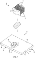
- FIG. 1 is an exploded view of a cold plate 130 used for thermal management of an inductor 110 according to one or more embodiments.
- the exploded view shows encapsulant 120, referred to also as potting material, and an inductor 110 above the cold plate 130.
- the encapsulant 120 is thermally conductive but electrically insulating.
- the encapsulant 120 encapsulates the inductor 110 and electrically separates the inductor 110 from a cavity 140 of the cold plate 130 while conducting heat from the inductor 110 to the cavity 140.
- the inductor 110 shown in FIG. 1 is a bobbin wound inductor.
- the windings 115 are pre-wound onto a bobbin 117 and then assembled on a core 105, as shown.
- the core 105 may be a laminated or taped wound silicon steel alloy, nick-iron alloy, cobalt alloy, or ferrite, for example.
- the two sets of windings 115 may be copper.
- the cavity 140 of the cold plate 130 is machined within a surface 135 of a first side 137 for seating the inductor 110.
- the inductor 110 dissipates heat that is removed according to one or more embodiments in order to maintain the temperature of the inductor 110 below a predefined limit.
- the cavity 140 of the cold plate 130 that seats the inductor 110 is further detailed with reference to FIG. 2 .
- the cold plate 130 has a second surface 145, opposite the surface 135, on a second side 147.
- components could be attached to both the surface 135 and second surface 145 of the cold plate 130.
- the thickness of the first side 137 is greater than the thickness of the second side 147 to accommodate the cavity 140, and components are only disposed on the surface 135.
- the exemplary cold plate 130 may be referred to as a one-sided.
- An inlet 150 facilitates an inflow of coolant 170 through a flow channel 610 ( FIG. 6 ) within the cold plate 130.
- the flow channel 610 may be formed as a pipe with fins for additional heat transfer.
- the flow channel 610 within the cold plate 130 may be formed in a pattern to allow the coolant 170 to absorb heat from different areas of the surface 135 as it moves from the inlet 150 to the outlet 160. That is, heat from the components on the surface 135, or both surfaces 135, 145, is conducted into the coolant 170, which carries the heat out via the outlet 160.
- Exemplary coolants 170 include ethylene glycol with water (EGW), propylene glycol with water (PGW), and polyalphaolefin (PAO). The cross-section indicated through B-B in shown in FIG. 6 .
- FIG. 2 shows aspects of the cavity 140 used to perform thermal management of the inductor 110 on a cold plate 130 according to one or more embodiments.
- the cavity 140 is machined as an integral part of the cold plate 130.
- the cold plate 130 and, thus, the cavity 140 are aluminum or copper, for example.
- the cavity 140 is defined by an outer wall 210 and includes a center plate 220.
- the center plate 220 does not extend from one side of the outer wall 210 to accommodate the core 105 of the inductor 110 in the cavity 140 as shown in FIG. 5 , for example.
- the center plate 220 defines first or core portions 240 of the cavity on either end of the center plate 220.
- the center plate 220 also defines second or winding portions 250 on either side of the center plate 220.
- the core portions 240 of the cavity 140 which are perpendicular to the center plate 220, support the parts of the core 105 of the inductor 110 that do not include the bobbins 117 and windings 115.
- the outer wall 210 corresponding with the core portions 240 is curved.
- the winding portions 250 of the cavity 140 which are parallel to the center plate 220, support the bobbins 117 and windings 115 of the inductor 110.
- the outer wall 210 corresponding with the winding portions 250 is straight.
- the floor or base 230 of the cavity 140 ultimately conducts the heat dissipated by the inductor 110, the heat source, to the coolant 170, the heat sink.
- the base 230 has a different thickness in the core portions 240 than in the winding portions 250, as discussed with reference to FIG. 7 .
- the heat conduction through the base 230 is further discussed with reference to FIGS. 8 and 9 .
- other components, additional to the inductor 110 may be mounted on the surface 135 of the cold plate 130. Additionally, another one or more cavities 140 to seat another one or more inductors 110 may also be integrated into the surface 135.
- FIG. 3 shows an example of multiple cavities 140 to perform thermal management according to one or more embodiments.
- Two cavities 140a and 140b (generally referred to as 140) to accommodate two inductors 110 are shown in FIG. 3 . While two cavities 140 are shown in the exemplary case, the number of cavities 140 and corresponding inductors 110 on the cold plate 130 is based on heat dissipation. That is, a particular number of inductors 110 and other components are placed on the surface 135 in consideration of the heat that they dissipate and the cooling capacity of the cold plate 130. The overall cooling capacity of the cold plate 130 is based on several factors including the size and thickness of the surface 135 and the temperature of the coolant 170. As FIG.
- each cavity 140 includes a corresponding outer wall 210a, 210b (generally referred to as 210) and center plate 220a, 220b (generally referred to as 220).
- the two cavities 140a, 140b have a shared wall 310 that is part of both the outer wall 210a and the outer wall 210b.
- FIG. 4 shows a cold plate 130 that provides thermal management of an inductor 110 seated in the cavity 140 according to one or more embodiments. As FIG. 4 indicates, only the encapsulant 120 is visible after the inductor 110 is fully installed in the cavity 140. The encapsulant 120 surrounds the inductor 110 such that no portion of the inductor 110 contacts the cavity 140. This is illustrated in FIG. 5 with a cross-section across A-A.
- FIG. 5 is a cross-sectional view A-A of an inductor 110 in a cavity 140 that performs thermal management according to one or more embodiments.
- the cross-section A-A is taken across the top of the cavity 140 that has the inductor 110 within.
- a top layer of encapsulant 120, windings 115a, 115b (generally referred to as 115), and bobbins 117a, 117b (generally referred to as 117) is removed exposing the core 105.
- encapsulant 120 separates each of the windings 115 and bobbins 117 from the center plate 220.
- the encapsulant 120 also separates the windings 115, the bobbins 117, and the core 105 from the outer wall 210.
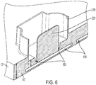
- FIG. 6 is a cross-sectional view B-B of a cavity 140 that performs thermal management according to one or more embodiments.
- the cross-section B-B is taken through the cavity 140 to expose the center plate 220 and the flow channel 610 between the first side 137 and second side 147.
- the cross-sectional view indicates that the thickness T of the first side 137 of the cold plate 130 that includes the cavity 140 is greater than the thickness t of the second side 147 of the cold plate 130. Sections of the flow channel 610 are visible within the cold plate 130.
- the cavity 140 is machined to be an integral part of the cold plate 130.
- the outer wall 210 and center plate 220 are machined from the material of the cold plate 130.
- thermal interface resistances are eliminated between different aspects of the cavity 140.
- the absence of thermal interface resistance maximizes heat dissipation from the source (i.e., the inductor 110).
- the base 230 of the cavity 140 ultimately conducts the heat from the cavity 140 to the heat sink, the coolant 170.
- the thickness Bt of even the thickest part of this base 230 is minimized, with consideration to structural integrity, to maximize heat transfer from the base 230 to the coolant 170 flowing through the flow channel 610.
- the base 230 actually includes two thicknesses. This is indicated in FIG. 7 .
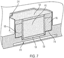
- FIG. 7 is a cross-sectional view detailing aspects of the base 230 of the cavity 140 that performs thermal management according to one or more embodiments.
- the center plate 220 is removed from the view shown in FIG. 7 and the inductor 110 is shown in the cavity 140.
- This view clarifies that the base 230 of the cavity 140 includes a thicker portion 710 that supports the core 105 of the inductor 110 and also includes a thinner portion 720 that supports the bobbins 117 and windings 115 of the inductor 110.
- the thicker portions 710 are on opposite ends of the cavity 140 and are perpendicular to the center plate 220 on either end of the center plate 220.
- the thicker portions 710 correspond with the core portions 240 of the cavity 140 indicated in FIG. 2 .
- the thinner portions 720 of the base 230 correspond with the winding portions 250 of the cavity 140 indicated in FIG. 2 .
- the view of FIG. 7 indicates that the encapsulant 120 that conducts heat from the inductor 110 to the cavity 140 is above, below, and on every side of the inductor 110.
- FIG. 8 shows heat flow from the inductor 110 into the cavity 140 according to one or more embodiments.
- the cross-sectional view across B-B as shown in FIG. 5 is shown in FIG. 8 .
- the top layer of encapsulant 120, windings 115, and bobbins 117 have been removed.
- the encapsulant 120 surrounding the inductor 110 on all sides is shown.
- This heat flow is both inward into the center plate 220 via encapsulant 120 and outward into the outer wall 210 via encapsulant 120.
- one or both of the portions of the outer wall 210 that are parallel to the center plate 220 may be shared walls 310 when two or more cavities 140 are part of the cold plate 130.
- FIG. 9 shows heat from the cavity 140 to the coolant 170 according to one or more embodiments.
- the cross-sectional view along A-A as shown in FIG. 6 is shown in FIG. 9 .
- the flow channel 610 between the first side 137 and second side 147 is visible.
Landscapes
- Engineering & Computer Science (AREA)
- Power Engineering (AREA)
- Cooling Or The Like Of Electrical Apparatus (AREA)
Abstract
Description
- Exemplary embodiments pertain to the art of thermal management and, in particular, to thermal management of an inductor on a cold plate.
- A liquid cold plate is a platform for mounting power electronic components. The cold plate provides localized cooling to the components by transferring heat from the components mounted on one or both surfaces to the liquid flowing within. One of the components that may be placed on a cold plate is an inductor. An inductor is a passive two-terminal electrical component that stores energy in a magnetic field when current flows through it. Generally, in inductor includes an insulated wire wound around a core as a coil.
- In one embodiment, a cold plate includes a first side with a first surface, and a second side, opposite the first side, with a second surface opposite the first surface. The cold plate also includes a flow channel formed between the first side and the second side, and a cavity integrally machined into the first surface of the first side. The cavity seats an inductor and is defined by an outer wall and a base with thicker sections and thinner sections such that even the thicker sections of the base are thinner than a thickness of the first surface.
- Additionally or alternatively, in this or other embodiments, the cold plate also includes an inlet to channel coolant into the flow channel.
- Additionally or alternatively, in this or other embodiments, the cold plate also includes an outlet to channel the coolant out of the flow channel.
- Additionally or alternatively, in this or other embodiments, a thickness of the first side is greater than a thickness of the second side.
- Additionally or alternatively, in this or other embodiments, the cavity includes first portions, second portions, and a center plate.
- Additionally or alternatively, in this or other embodiments, the first portions have the base with the thicker sections and each of the thicker sections supports a core of the inductor.
- Additionally or alternatively, in this or other embodiments, the outer wall corresponding with each of the first portions is curved.
- Additionally or alternatively, in this or other embodiments, the first portions are on opposite ends of the center plate such that the outer wall corresponding with each of the first portions is perpendicular to the center plate.
- Additionally or alternatively, in this or other embodiments, the second portions have the base with the thinner sections and each of the thinner sections supports windings of the inductor.
- Additionally or alternatively, in this or other embodiments, the outer wall corresponding with each of the second portions is straight.
- Additionally or alternatively, in this or other embodiments, the second portions are on opposite sides of the center plate such that the outer wall corresponding with each of the second portions is parallel with the center plate.
- Additionally or alternatively, in this or other embodiments, the cold plate also includes one or more additional ones of the cavity to seat one or more additional ones of the inductor.
- Additionally or alternatively, in this or other embodiments, the outer wall of at least one of the one or more additional ones of the cavity is part of the outer wall of the cavity.
- In another embodiment, a method of fabricating a cold plate includes machining a flow channel between a first side with a first surface and a second side, opposite the first side, with a second surface opposite the first surface. The method also includes machining a cavity into the first surface of the first side. The cavity seats an inductor and is defined by an outer wall and a base with thicker sections and thinner sections such that even the thicker sections of the base are thinner than a thickness of the first surface.
- Additionally or alternatively, in this or other embodiments, the method also includes forming an inlet to channel coolant into the flow channel, forming an outlet to channel the coolant out of the flow channel, and positioning the flow channel such that a thickness of the first side is greater than a thickness of the second side.
- Additionally or alternatively, in this or other embodiments, the machining the cavity includes machining first portions, second portions, and a center plate.
- Additionally or alternatively, in this or other embodiments, the machining the first portions includes forming the first portions with the base with the thicker sections. Each of the thicker sections supports a core of the inductor. The machining the second portions includes forming the second portions with the base with the thinner sections. Each of the thinner sections supports windings of the inductor.
- Additionally or alternatively, in this or other embodiments, the method also includes machining the outer wall of each of the first portions to be curved and machining the outer wall of each of the second portions to be straight.
- Additionally or alternatively, in this or other embodiments, the machining the cavity includes machining the first portions to be on opposite ends of the center plate such that the outer wall of each of the first portions is perpendicular to the center plate, and machining the second portions to be on opposite sides of the center plate such that the outer wall of each of the second portions is parallel to the center plate.
- Additionally or alternatively, in this or other embodiments, the method also includes machining one or more additional ones of the cavity to seat one or more additional ones of the inductor. The machining includes the outer wall of at least one of the one or more additional ones of the cavity being part of the outer wall of the cavity.
- The following descriptions should not be considered limiting in any way. With reference to the accompanying drawings, like elements are numbered alike:
-
FIG. 1 is an exploded view of a cold plate used for thermal management of an inductor according to one or more embodiments -
FIG. 2 shows aspects of the cavity used to perform thermal management of the inductor on a cold plate according to one or more embodiments; -
FIG. 3 shows an example of multiple cavities to perform thermal management according to one or more embodiments; -
FIG. 4 shows a cold plate that provides thermal management of an inductor seated in the cavity according to one or more embodiments; -
FIG. 5 is a cross-sectional view A-A of an inductor in a cavity that performs thermal management according to one or more embodiments; -
FIG. 6 is a cross-sectional view B-B of a cavity that performs thermal management according to one or more embodiments; -
FIG. 7 is a cross-sectional view detailing aspects of the base of the cavity that performs thermal management according to one or more embodiments; -
FIG. 8 shows heat flow from the inductor into the cavity according to one or more embodiments; and -
FIG. 9 shows heat from the cavity to the coolant according to one or more embodiments. - A detailed description of one or more embodiments of the disclosed apparatus and method are presented herein by way of exemplification and not limitation with reference to the Figures.
- As previously noted, a cold plate can support and cool electronic components. Embodiments of the systems and methods detailed herein relate to thermal management of an inductor on a cold plate. Specifically, a cavity is machined as an integral part of the cold plate to accommodate the inductor. As also detailed, more than one cavity may be machined to accommodate more than one inductor on the cold plate. The base of the cavity transfers heat from the inductor to a coolant flowing within the body of the cold plate in a flow channel.
-
FIG. 1 is an exploded view of acold plate 130 used for thermal management of aninductor 110 according to one or more embodiments. The exploded view shows encapsulant 120, referred to also as potting material, and aninductor 110 above thecold plate 130. The encapsulant 120 is thermally conductive but electrically insulating. Thus, theencapsulant 120 encapsulates theinductor 110 and electrically separates theinductor 110 from acavity 140 of thecold plate 130 while conducting heat from theinductor 110 to thecavity 140. Theinductor 110 shown inFIG. 1 is a bobbin wound inductor. In contrast to a toroidal inductor, for example, which includes coils wound directly onto a toroidal core, thewindings 115 are pre-wound onto abobbin 117 and then assembled on acore 105, as shown. Thecore 105 may be a laminated or taped wound silicon steel alloy, nick-iron alloy, cobalt alloy, or ferrite, for example. The two sets ofwindings 115 may be copper. Thecavity 140 of thecold plate 130 is machined within asurface 135 of afirst side 137 for seating theinductor 110. Theinductor 110 dissipates heat that is removed according to one or more embodiments in order to maintain the temperature of theinductor 110 below a predefined limit. - The
cavity 140 of thecold plate 130 that seats theinductor 110 is further detailed with reference toFIG. 2 . Thecold plate 130 has asecond surface 145, opposite thesurface 135, on asecond side 147. As previously noted, components could be attached to both thesurface 135 andsecond surface 145 of thecold plate 130. According to exemplary embodiments, the thickness of thefirst side 137 is greater than the thickness of thesecond side 147 to accommodate thecavity 140, and components are only disposed on thesurface 135. Thus, the exemplarycold plate 130 may be referred to as a one-sided. - An inlet 150 facilitates an inflow of
coolant 170 through a flow channel 610 (FIG. 6 ) within thecold plate 130. Theflow channel 610 may be formed as a pipe with fins for additional heat transfer. Theflow channel 610 within thecold plate 130 may be formed in a pattern to allow thecoolant 170 to absorb heat from different areas of thesurface 135 as it moves from the inlet 150 to theoutlet 160. That is, heat from the components on thesurface 135, or bothsurfaces coolant 170, which carries the heat out via theoutlet 160.Exemplary coolants 170 include ethylene glycol with water (EGW), propylene glycol with water (PGW), and polyalphaolefin (PAO). The cross-section indicated through B-B in shown inFIG. 6 . -
FIG. 2 shows aspects of thecavity 140 used to perform thermal management of theinductor 110 on acold plate 130 according to one or more embodiments. As previously noted, thecavity 140 is machined as an integral part of thecold plate 130. Thecold plate 130 and, thus, thecavity 140 are aluminum or copper, for example. Thecavity 140 is defined by anouter wall 210 and includes acenter plate 220. Thecenter plate 220 does not extend from one side of theouter wall 210 to accommodate thecore 105 of theinductor 110 in thecavity 140 as shown inFIG. 5 , for example. - The
center plate 220 defines first orcore portions 240 of the cavity on either end of thecenter plate 220. Thecenter plate 220 also defines second or windingportions 250 on either side of thecenter plate 220. Thecore portions 240 of thecavity 140, which are perpendicular to thecenter plate 220, support the parts of thecore 105 of theinductor 110 that do not include thebobbins 117 andwindings 115. Theouter wall 210 corresponding with thecore portions 240 is curved. The windingportions 250 of thecavity 140, which are parallel to thecenter plate 220, support thebobbins 117 andwindings 115 of theinductor 110. Theouter wall 210 corresponding with the windingportions 250 is straight. - The floor or
base 230 of thecavity 140 ultimately conducts the heat dissipated by theinductor 110, the heat source, to thecoolant 170, the heat sink. Thebase 230 has a different thickness in thecore portions 240 than in the windingportions 250, as discussed with reference toFIG. 7 . The heat conduction through thebase 230 is further discussed with reference toFIGS. 8 and 9 . It should be understood that other components, additional to theinductor 110, may be mounted on thesurface 135 of thecold plate 130. Additionally, another one ormore cavities 140 to seat another one ormore inductors 110 may also be integrated into thesurface 135. -
FIG. 3 shows an example ofmultiple cavities 140 to perform thermal management according to one or more embodiments. Twocavities inductors 110 are shown inFIG. 3 . While twocavities 140 are shown in the exemplary case, the number ofcavities 140 andcorresponding inductors 110 on thecold plate 130 is based on heat dissipation. That is, a particular number ofinductors 110 and other components are placed on thesurface 135 in consideration of the heat that they dissipate and the cooling capacity of thecold plate 130. The overall cooling capacity of thecold plate 130 is based on several factors including the size and thickness of thesurface 135 and the temperature of thecoolant 170. AsFIG. 3 indicates, eachcavity 140 includes a correspondingouter wall center plate cavities wall 310 that is part of both theouter wall 210a and theouter wall 210b. -
FIG. 4 shows acold plate 130 that provides thermal management of aninductor 110 seated in thecavity 140 according to one or more embodiments. AsFIG. 4 indicates, only theencapsulant 120 is visible after theinductor 110 is fully installed in thecavity 140. Theencapsulant 120 surrounds theinductor 110 such that no portion of theinductor 110 contacts thecavity 140. This is illustrated inFIG. 5 with a cross-section across A-A. -
FIG. 5 is a cross-sectional view A-A of aninductor 110 in acavity 140 that performs thermal management according to one or more embodiments. AsFIG. 4 indicates, the cross-section A-A is taken across the top of thecavity 140 that has theinductor 110 within. Specifically, a top layer ofencapsulant 120,windings bobbins core 105. AsFIG. 5 indicates,encapsulant 120 separates each of thewindings 115 andbobbins 117 from thecenter plate 220. Theencapsulant 120 also separates thewindings 115, thebobbins 117, and the core 105 from theouter wall 210. -
FIG. 6 is a cross-sectional view B-B of acavity 140 that performs thermal management according to one or more embodiments. AsFIG. 1 indicates, the cross-section B-B is taken through thecavity 140 to expose thecenter plate 220 and theflow channel 610 between thefirst side 137 andsecond side 147. The cross-sectional view indicates that the thickness T of thefirst side 137 of thecold plate 130 that includes thecavity 140 is greater than the thickness t of thesecond side 147 of thecold plate 130. Sections of theflow channel 610 are visible within thecold plate 130. - As previously noted, the
cavity 140 is machined to be an integral part of thecold plate 130. Thus, theouter wall 210 andcenter plate 220 are machined from the material of thecold plate 130. As a result, thermal interface resistances are eliminated between different aspects of thecavity 140. The absence of thermal interface resistance maximizes heat dissipation from the source (i.e., the inductor 110). As previously noted, thebase 230 of thecavity 140 ultimately conducts the heat from thecavity 140 to the heat sink, thecoolant 170. The thickness Bt of even the thickest part of thisbase 230 is minimized, with consideration to structural integrity, to maximize heat transfer from the base 230 to thecoolant 170 flowing through theflow channel 610. The base 230 actually includes two thicknesses. This is indicated inFIG. 7 . -
FIG. 7 is a cross-sectional view detailing aspects of thebase 230 of thecavity 140 that performs thermal management according to one or more embodiments. Thecenter plate 220 is removed from the view shown inFIG. 7 and theinductor 110 is shown in thecavity 140. This view clarifies that thebase 230 of thecavity 140 includes athicker portion 710 that supports thecore 105 of theinductor 110 and also includes athinner portion 720 that supports thebobbins 117 andwindings 115 of theinductor 110. Thethicker portions 710 are on opposite ends of thecavity 140 and are perpendicular to thecenter plate 220 on either end of thecenter plate 220. Thethicker portions 710 correspond with thecore portions 240 of thecavity 140 indicated inFIG. 2 . Thethinner portions 720 of the base 230 correspond with the windingportions 250 of thecavity 140 indicated inFIG. 2 . The view ofFIG. 7 indicates that theencapsulant 120 that conducts heat from theinductor 110 to thecavity 140 is above, below, and on every side of theinductor 110. -
FIG. 8 shows heat flow from theinductor 110 into thecavity 140 according to one or more embodiments. The cross-sectional view across B-B as shown inFIG. 5 is shown inFIG. 8 . As such, the top layer ofencapsulant 120,windings 115, andbobbins 117 have been removed. Theencapsulant 120 surrounding theinductor 110 on all sides is shown. As the arrows indicate, heat flows into theheat conducting encapsulant 120 from thecore 105 andwindings 115. This heat flow is both inward into thecenter plate 220 viaencapsulant 120 and outward into theouter wall 210 viaencapsulant 120. As previously noted, one or both of the portions of theouter wall 210 that are parallel to thecenter plate 220 may be sharedwalls 310 when two ormore cavities 140 are part of thecold plate 130. -
FIG. 9 shows heat from thecavity 140 to thecoolant 170 according to one or more embodiments. The cross-sectional view along A-A as shown inFIG. 6 is shown inFIG. 9 . Thus, theflow channel 610 between thefirst side 137 andsecond side 147 is visible. As the arrows indicate, heat flows from theinductor 110 throughencapsulant 120 to theouter wall 210 andcenter plate 220 of thecavity 140 and this heat is conducted through thebase 230 of thecavity 140 to thecoolant 170 flowing through theflow channel 610. - The term "about" is intended to include the degree of error associated with measurement of the particular quantity based upon the equipment available at the time of filing the application.
- The terminology used herein is for the purpose of describing particular embodiments only and is not intended to be limiting of the present disclosure. As used herein, the singular forms "a", "an" and "the" are intended to include the plural forms as well, unless the context clearly indicates otherwise. It will be further understood that the terms "comprises" and/or "comprising," when used in this specification, specify the presence of stated features, integers, steps, operations, elements, and/or components, but do not preclude the presence or addition of one or more other features, integers, steps, operations, element components, and/or groups thereof.
- While the present disclosure has been described with reference to an exemplary embodiment or embodiments, it will be understood by those skilled in the art that various changes may be made and equivalents may be substituted for elements thereof without departing from the scope of the invention as defined by the claims. In addition, many modifications may be made to adapt a particular situation or material to the teachings of the present disclosure without departing from the scope of the claims. Therefore, it is intended that the present disclosure not be limited to the particular embodiment disclosed as the best mode contemplated for carrying out this present disclosure, but that the present disclosure will include all embodiments falling within the scope of the claims.
Claims (15)
- A cold plate comprising:a first side (137) with a first surface (135);a second side (147), opposite the first side, with a second surface (145) opposite the first surface;a flow channel (610) formed between the first side and the second side; anda cavity (140) integrally machined into the first surface of the first side, wherein the cavity is configured to seat an inductor (110) and is defined by an outer wall (205) and a base (230) with thicker sections and thinner sections such that even the thicker sections of the base are thinner than a thickness of the first surface.
- The cold plate according to claim 1, further comprising an inlet (150) configured to channel coolant into the flow channel.
- The cold plate according to claim 2, further comprising an outlet (160) configured to channel the coolant out of the flow channel.
- The cold plate according to any preceding claim, wherein a thickness of the first side is greater than a thickness of the second side.
- The cold plate according to any preceding claim, wherein the cavity includes first portions (240), second portions (250), and a center plate (220).
- The cold plate according to claim 5, wherein the first portions have the base with the thicker sections and each of the thicker sections is configured to support a core of the inductor, and optionally wherein the outer wall corresponding with each of the first portions is curved, and optionally wherein the first portions are on opposite ends of the center plate such that the outer wall corresponding with each of the first portions is perpendicular to the center plate.
- The cold plate according to claim 5, wherein the second portions have the base with the thinner sections and each of the thinner sections is configured to support windings of the inductor, and optionally wherein the outer wall corresponding with each of the second portions is straight, and optionally wherein the second portions are on opposite sides of the center plate such that the outer wall corresponding with each of the second portions is parallel with the center plate.
- The cold plate according to any preceding claim, further comprising one or more additional ones of the cavity configured to seat one or more additional ones of the inductor, and optionally wherein the outer wall of at least one of the one or more additional ones of the cavity is part of the outer wall of the cavity.
- A method of fabricating a cold plate, the method comprising:machining a flow channel between a first side with a first surface and a second side, opposite the first side, with a second surface opposite the first surface; andmachining a cavity into the first surface of the first side, wherein the cavity is configured to seat an inductor and the machining the cavity includes defining the cavity with an outer wall and a base with thicker sections and thinner sections such that even the thicker sections of the base are thinner than a thickness of the first surface.
- The method according to claim 9, further comprising forming an inlet configured to channel coolant into the flow channel, forming an outlet configured to channel the coolant out of the flow channel, and positioning the flow channel such that a thickness of the first side is greater than a thickness of the second side.
- The method according to claim 9 or 10, wherein the machining the cavity includes machining first portions, second portions, and a center plate.
- The method according to claim 11, wherein the machining the first portions includes forming the first portions with the base with the thicker sections, each of the thicker sections being configured to support a core of the inductor, and the machining the second portions includes forming the second portions with the base with the thinner sections, each of the thinner sections being configured to support windings of the inductor.
- The method according to claim 11 or 12, further comprising machining the outer wall of each of the first portions to be curved and machining the outer wall of each of the second portions to be straight.
- The method according to claim 13, wherein the machining the cavity includes machining the first portions to be on opposite ends of the center plate such that the outer wall of each of the first portions is perpendicular to the center plate, and machining the second portions to be on opposite sides of the center plate such that the outer wall of each of the second portions is parallel to the center plate.
- The method according to any of claims 9 to 14, further comprising machining one or more additional ones of the cavity to seat one or more additional ones of the inductor, wherein the machining includes the outer wall of at least one of the one or more additional ones of the cavity being part of the outer wall of the cavity.
Applications Claiming Priority (1)
| Application Number | Priority Date | Filing Date | Title |
|---|---|---|---|
| US16/909,459 US11557419B2 (en) | 2020-06-23 | 2020-06-23 | Thermal management of inductor on a cold plate |
Publications (1)
| Publication Number | Publication Date |
|---|---|
| EP3929950A1 true EP3929950A1 (en) | 2021-12-29 |
Family
ID=76584412
Family Applications (1)
| Application Number | Title | Priority Date | Filing Date |
|---|---|---|---|
| EP21181207.8A Pending EP3929950A1 (en) | 2020-06-23 | 2021-06-23 | Thermal management of inductor on a cold plate |
Country Status (2)
| Country | Link |
|---|---|
| US (1) | US11557419B2 (en) |
| EP (1) | EP3929950A1 (en) |
Cited By (1)
| Publication number | Priority date | Publication date | Assignee | Title |
|---|---|---|---|---|
| EP4712115A1 (en) * | 2024-09-12 | 2026-03-18 | Delta Electronics, Inc. | Magnetic component |
Families Citing this family (1)
| Publication number | Priority date | Publication date | Assignee | Title |
|---|---|---|---|---|
| US12119156B2 (en) * | 2022-10-11 | 2024-10-15 | Lunar Energy, Inc. | Inductor thermal management system |
Citations (8)
| Publication number | Priority date | Publication date | Assignee | Title |
|---|---|---|---|---|
| JP2004319618A (en) * | 2003-04-14 | 2004-11-11 | Tokyo Seiden Kk | Reactor |
| WO2006016554A1 (en) * | 2004-08-10 | 2006-02-16 | Tamura Corporation | Reactor |
| JP2008182151A (en) * | 2007-01-26 | 2008-08-07 | Denso Corp | Reactor |
| JP2009147041A (en) * | 2007-12-13 | 2009-07-02 | Sumitomo Electric Ind Ltd | Reactor |
| JP2009188033A (en) * | 2008-02-04 | 2009-08-20 | Sumitomo Electric Ind Ltd | Reactor mounting structure |
| JP2015090912A (en) * | 2013-11-06 | 2015-05-11 | トヨタ自動車株式会社 | Reactor |
| US20180272889A1 (en) * | 2017-03-27 | 2018-09-27 | Toyota Jidosha Kabushiki Kaisha | Fuel cell unit |
| US20200135378A1 (en) * | 2018-10-31 | 2020-04-30 | Hamilton Sundstrand Corporation | Thermal management of high power inductors |
Family Cites Families (6)
| Publication number | Priority date | Publication date | Assignee | Title |
|---|---|---|---|---|
| US9066453B2 (en) | 2012-03-06 | 2015-06-23 | Mission Motor Company | Power electronic system and method of assembly |
| JP2013201377A (en) | 2012-03-26 | 2013-10-03 | Panasonic Corp | Reactor device |
| EP2874162B1 (en) | 2012-07-13 | 2017-06-07 | Hitachi Metals, Ltd. | Case unit and electronic component |
| KR101646375B1 (en) | 2014-11-05 | 2016-08-12 | 현대자동차주식회사 | Inductor apparatus |
| JP6759609B2 (en) * | 2016-02-04 | 2020-09-23 | Tdk株式会社 | Coil parts |
| JP6234614B1 (en) * | 2016-05-31 | 2017-11-22 | 新電元工業株式会社 | Coil structure and magnetic parts |
-
2020
- 2020-06-23 US US16/909,459 patent/US11557419B2/en active Active
-
2021
- 2021-06-23 EP EP21181207.8A patent/EP3929950A1/en active Pending
Patent Citations (8)
| Publication number | Priority date | Publication date | Assignee | Title |
|---|---|---|---|---|
| JP2004319618A (en) * | 2003-04-14 | 2004-11-11 | Tokyo Seiden Kk | Reactor |
| WO2006016554A1 (en) * | 2004-08-10 | 2006-02-16 | Tamura Corporation | Reactor |
| JP2008182151A (en) * | 2007-01-26 | 2008-08-07 | Denso Corp | Reactor |
| JP2009147041A (en) * | 2007-12-13 | 2009-07-02 | Sumitomo Electric Ind Ltd | Reactor |
| JP2009188033A (en) * | 2008-02-04 | 2009-08-20 | Sumitomo Electric Ind Ltd | Reactor mounting structure |
| JP2015090912A (en) * | 2013-11-06 | 2015-05-11 | トヨタ自動車株式会社 | Reactor |
| US20180272889A1 (en) * | 2017-03-27 | 2018-09-27 | Toyota Jidosha Kabushiki Kaisha | Fuel cell unit |
| US20200135378A1 (en) * | 2018-10-31 | 2020-04-30 | Hamilton Sundstrand Corporation | Thermal management of high power inductors |
Cited By (1)
| Publication number | Priority date | Publication date | Assignee | Title |
|---|---|---|---|---|
| EP4712115A1 (en) * | 2024-09-12 | 2026-03-18 | Delta Electronics, Inc. | Magnetic component |
Also Published As
| Publication number | Publication date |
|---|---|
| US20210398732A1 (en) | 2021-12-23 |
| US11557419B2 (en) | 2023-01-17 |
Similar Documents
| Publication | Publication Date | Title |
|---|---|---|
| US8928441B2 (en) | Liquid cooled magnetic component with indirect cooling for high frequency and high power applications | |
| EP2858076B1 (en) | Magnetic devices with integral cooling channels | |
| US7920039B2 (en) | Thermally enhanced magnetic transformer | |
| EP2711941B1 (en) | Electrical inductor assembly and method of cooling an electrical inductor assembly | |
| JP6234537B1 (en) | Power converter | |
| CN110660563A (en) | Magnetic assembly and power module | |
| US7911308B2 (en) | Low thermal impedance conduction cooled magnetics | |
| US11557419B2 (en) | Thermal management of inductor on a cold plate | |
| CN111554477A (en) | Hybrid transformer for DC/DC converter | |
| US12418208B2 (en) | Displacement body for a rotor and correspondingly configured rotor | |
| CN116368586A (en) | Winding holders for magnetic parts of electrical assemblies | |
| KR20030007477A (en) | Coil with cooling means | |
| EP3929949B1 (en) | Thermal management of toroidal transformer on a cold plate | |
| EP3929948B1 (en) | Thermal management of toroidal transformer mounted on a printed wiring board stiffener | |
| JP2008021688A (en) | Reactor core | |
| US11443882B2 (en) | Coil device | |
| EP2568484B1 (en) | Electro-magnetic device having a polymer housing | |
| US20230317345A1 (en) | Power magnetic component | |
| JP7110863B2 (en) | Reactor | |
| US20250374415A1 (en) | Pcb core laminate for wireless power charger and method of manufacturing the same | |
| JP6651592B1 (en) | Reactor cooling structure and power converter | |
| JP2023547212A (en) | inductor coil | |
| US12160161B1 (en) | Immersion-cooled axial flux electric motors and methods of operating thereof | |
| US20250374416A1 (en) | Pcb core laminate for wireless power charger and method of manufacturing the same | |
| US20240120147A1 (en) | Flat coil and coil device |
Legal Events
| Date | Code | Title | Description |
|---|---|---|---|
| PUAI | Public reference made under article 153(3) epc to a published international application that has entered the european phase |
Free format text: ORIGINAL CODE: 0009012 |
|
| STAA | Information on the status of an ep patent application or granted ep patent |
Free format text: STATUS: THE APPLICATION HAS BEEN PUBLISHED |
|
| AK | Designated contracting states |
Kind code of ref document: A1 Designated state(s): AL AT BE BG CH CY CZ DE DK EE ES FI FR GB GR HR HU IE IS IT LI LT LU LV MC MK MT NL NO PL PT RO RS SE SI SK SM TR |
|
| B565 | Issuance of search results under rule 164(2) epc |
Effective date: 20211125 |
|
| STAA | Information on the status of an ep patent application or granted ep patent |
Free format text: STATUS: REQUEST FOR EXAMINATION WAS MADE |
|
| 17P | Request for examination filed |
Effective date: 20220629 |
|
| RBV | Designated contracting states (corrected) |
Designated state(s): AL AT BE BG CH CY CZ DE DK EE ES FI FR GB GR HR HU IE IS IT LI LT LU LV MC MK MT NL NO PL PT RO RS SE SI SK SM TR |
|
| STAA | Information on the status of an ep patent application or granted ep patent |
Free format text: STATUS: EXAMINATION IS IN PROGRESS |
|
| 17Q | First examination report despatched |
Effective date: 20230717 |