EP3929761A1 - A graph database management system - Google Patents
A graph database management system Download PDFInfo
- Publication number
- EP3929761A1 EP3929761A1 EP20182082.6A EP20182082A EP3929761A1 EP 3929761 A1 EP3929761 A1 EP 3929761A1 EP 20182082 A EP20182082 A EP 20182082A EP 3929761 A1 EP3929761 A1 EP 3929761A1
- Authority
- EP
- European Patent Office
- Prior art keywords
- memory
- storing
- data
- management system
- graph database
- Prior art date
- Legal status (The legal status is an assumption and is not a legal conclusion. Google has not performed a legal analysis and makes no representation as to the accuracy of the status listed.)
- Granted
Links
Images



Classifications
-
- G—PHYSICS
- G06—COMPUTING OR CALCULATING; COUNTING
- G06F—ELECTRIC DIGITAL DATA PROCESSING
- G06F16/00—Information retrieval; Database structures therefor; File system structures therefor
- G06F16/20—Information retrieval; Database structures therefor; File system structures therefor of structured data, e.g. relational data
- G06F16/22—Indexing; Data structures therefor; Storage structures
- G06F16/2228—Indexing structures
-
- G—PHYSICS
- G06—COMPUTING OR CALCULATING; COUNTING
- G06F—ELECTRIC DIGITAL DATA PROCESSING
- G06F16/00—Information retrieval; Database structures therefor; File system structures therefor
- G06F16/20—Information retrieval; Database structures therefor; File system structures therefor of structured data, e.g. relational data
- G06F16/28—Databases characterised by their database models, e.g. relational or object models
Definitions
- Various example embodiments relate to a graph database management system and to a method for manipulating data in a graph database management system.
- Graph databases use graph structures such as nodes and edges to represent and store a vast amount of slowly changing connected data, such as a music database.
- Graph databases use an entity-relationship model that describes how nodes are interconnected or related. According to the entity-relationship model, each node represents an entity such as a parameter, and each edge represents a connection or relation between different parameters. Data is thus represented and stored in the form of data records characterizing the relationship between the different entities.
- graph databases are gaining popularity in new application domains such as sensor networks where millions of sensors are sensing data at a very high frequency, for example, every few seconds.
- a sensor network may be configured to count the people entering and exiting, to count the cars entering and exiting a parking lot, or it may even be integrated in a traffic control infrastructure to count the cars before a traffic light.
- the ability of the graph databases to handle fast-changing, highly dynamic data becomes crucial.
- a graph database management system comprising at least one processor and at least one memory including computer program code, the at least one memory and computer program code configured, with the at least one processor, to perform storing, in the memory, data in the form of data records in accordance with an entity-relationship model, the data records comprising at least a subject, a predicate, and an object, the database management system being further configured to perform:
- the graph database management system stores the data in its memory in the form of data records in accordance with the entity-relationship model.
- entity-relationship model is the Resource Description Framework, RDF, data model.
- the RDF data model describes the data in the form of subject-predicate-object expression, known as triples.
- the subject defines an entity
- the object defines either an entity or a value
- the predicate defines the relation between them.
- the information that "Sensor S_A is a CO2 sensor" and that "Sensor S_A has a value of 1000ppm" may be recorded as two triples.
- the first triple will have a subject denoting "Sensor S_A”, a predicate denoting "is a” and an object denoting the entity "CO2 sensor”, and the second triple will have a subject denoting "Sensor S_A”, a predicate denoting "has a value of” and an object denoting the value "1000 ppm”.
- a data records may further contain additional fields such as time, a higher-level grouping concept of triples, etc.
- the higher-level grouping concept of triples may be for example a subgraph unique identifier.
- the graph database management system stores the memory address of the object.
- the database management system is configured to derive the memory address of the respective object, i.e. the location in the memory where the value of the respective object is stored.
- the memory may comprise a cache memory for short term storage and a main memory for long term storage such as a hard disk.
- the cache memory may comprise one or more cache levels, for example, two or even three levels. The different cache levels are commonly referred to as L1, L2 and L3 levels.
- a data record thus may be stored in the main memory or in both the cache, for example at one or more cache levels and the main memory.
- the memory address for the main memory or memory addresses for both the cache and the main memory may be derived depending on where the object is stored.
- the derived memory address is then associated with the respective object and the information is stored in the memory.
- the object value of the data record may be updated by overwriting the old value stored at the memory address with the new one.
- a fast update of the object's value in the graph database management system is enabled.
- This in turn enables the graph database management system to store and manage highly dynamic data in the graph database without modifying the manner in which data is stored in and queried from the graph database.
- the associating comprises: determining unique identifiers for the respective objects; and associating the memory addresses with the respective unique identifiers; and wherein the storing comprises storing the memory addresses and the respective unique identifiers in the form of a lookup table.
- the graph database management system determines unique identifiers for the respective data records.
- the unique identifiers are then associated with the memory addresses of the respective objects.
- This information i.e. the unique identifiers together with the associated memory addresses is recorded in the memory of the graph database management system.
- the information is stored in the form of a look-up table.
- the respective objects have a value varying over time.
- data records may be classified as static or dynamic.
- Static data records are characterized by a constant object value
- dynamic data records are characterized by an object's value varying over time.
- dynamic data records may be further classified as slowly varying, i.e. less dynamic, or a fast varying, i.e. highly dynamic, data.
- Storing the memory addresses associated with objects of dynamic data records allows limiting the amount of additional data stored in the memory and therefore minimizing the overall memory overhead.
- the graph database management system is further configured to perform, when storing, in the memory, a new data record having an object with a varying over time value:
- the graph database management system When storing new data records in the memory, i.e. when additional data is added, the graph database management system stores the new data records in the memory together with the one or memory addresses associated with the objects of the respective new data records. Depending on where the object is stored, the memory address for the main memory or memory addresses for both the cache and the main memory may be derived.
- the graph database management system is further configured to perform, when deleting, from the memory, a data record having an object with a varying over time value:
- the graph database management system is further configured to perform, when updating a value of a respective object:
- a data record may be stored in the main memory or in both the cache and the main memory.
- the graph database management system retrieves the one or more memory addresses associated with the respective object. This may be done by retrieving the memory addresses associated with the unique identifier of the data record of the object.
- the graph database management system is further configured to perform:
- an object value will be updated if a specific condition is satisfied.
- the condition may be stored in the memory in the form of data records. The condition may thus be retrieved by issuing a query for that condition.
- the graph database management system will then check whether the new object value satisfies the condition and if so, it will update, i.e. write, the new value in the one or more memory addresses associated with the respective object.
- condition implements a threshold or a range-bound.
- a condition may be a threshold or a range-bound of the object value.
- the range-bound may be defined by a minimum and a maximum value.
- the minimum and maximum values may be derived from object values observed over a period of time, i.e. a time series.
- the stored object value may thus be updated only if the new object value does not fall within the range-bound defined by the minimum and maximum values. This significantly reduces the write frequency while allowing to keep a usable model of the time series, i.e. in the form of a range-bound, in the graph database.
- the associating comprises: determining unique identifiers for the respective objects; and associating the memory addresses with the respective unique identifiers; and wherein the storing comprises storing the memory addresses and the respective unique identifiers in the form of a lookup table.
- the respective objects have a value varying over time.
- the method is further configured to perform, when updating a value of a respective object:
- the method is further configured to perform:
- the other example embodiments of the first example aspect may further be applied as example embodiments to the second example aspects.
- a computer program product comprising computer-executable instructions for performing the following steps when the program is run on a computer:
- the other example embodiments of the first example aspect may be applied as example embodiments to the second example aspect.
- a computer readable storage medium comprising computer-executable instructions for performing the following steps when the program is run on a computer:
- the various example embodiments of the first example aspect may be applied as example embodiments to the third and fourth example aspects.
- a graph database stores data or information in the form of data records.
- the data records are created based on an entity-relationship model.
- An example of an entity-relationship model is the Resource Description Framework, RDF, data model.
- the RDF data model describes the data in the form of subject-predicate-object expression, known as triples.
- the subject denotes the resource
- the predicate denotes properties or aspects of the resource with a value denoted in the object, or, expresses a relationship between the subject and the object when the object denotes another resource.
- Graph databases can be optimized either for querying, i.e. for reading data, or for writing data into the database. If the database is optimized for data querying, the data writing becomes slow, and vice versa.
- the present disclosure discloses a graph database management system optimized both for querying and storing data and more specifically of highly dynamic data in the graph database, while preserving the manner in which data is stored in and queried from the graph database.
- FIG.1 shows a wireless sensor network 100 comprising N sensors deployed in several different locations within an environment.
- the sensors monitor and record the physical conditions of the environment such as temperature, pollution levels, humidity, etc. The recorded information is then collected at a centralized location.
- a wireless sensor network is deployed in an office building to monitor the air quality as well as the number of people occupying the office building.
- the sensor network comprises six CO2 sensors 121 to 126 deployed in different rooms of the building 110. Sensors 121 and 122 are deployed in room 111, sensors 125 and 126 are deployed in room 114 and sensors 123 and 124 are deployed in rooms 112 and 113, respectively.
- the sensors record the CO2 level at a high frequency, for example, every 10 sec.
- the recorded CO2 levels are transmitted to the graph database management system 130 via a wireless channel 131.
- the graph database management system 130 thus receives a sensed CO2 level from a respective sensor at the frequency of 10 sec.
- the graph database management system 130 To monitor the air quality as well as the number of people occupying the rooms, the graph database management system 130 records a structural representation of the wireless sensor network as well as a characterization of the sensors. This information is stored in the form of data records, for example in the form of triples.
- FIG.2A shows the data records related to the CO2 sensor 121 stored in the graph database.
- a data record 200 comprises a subject 210, a predicate 220, and an object 230, where the subject and the object define two entities and the predicate the relation between them.
- the first data record in the table records that the sensor "S_A" has a value of "100". In this example, the value 100 is denoted in implicit units. In practive this value may correspond to a real CO2 measurement of 20ppm.
- the second data record in the table records that the sensor "S_A” is a CO2 sensor.
- the third data record records that the sensor "S_A" is located in the room “R_A”.
- the fourth records that the room “R_A” is a meeting room and the fifth data record records that the room “R_A” is located in building "B_A”. This way complete characterization of the wireless sensor network and the environment where the sensor is deployed is stored in the graph database.
- This information may be visually represented in the form of a graph as shown in FIG.2B , where the subjects 210 and the objects 230 are the nodes of the graph, represented as circles, and the predicates 220 are the connections between the graph nodes.
- the graph database management system 130 may alert that the air quality in a specific room is above or below a pre-determined limit and/or that a specific room is empty or occupied by one, two or more people.
- This may be performed by processing the recorded CO2 levels in a processing device 140.
- the processing device retrieves the CO2 levels of the respective sensors by querying or reading the objects' values of the respective sensors from the graph database, processes the retrieved values to estimate the room occupation and potentially issues an alert if the CO2 level of a respective room is higher than the health limit.
- the processing device 140 may be included in the graph database management system and thus forming part of it. Alternatively, the processing device 140 may be external to the graph database management system device. In both cases, the processing device 140 is configured to accesses the graph database 130 via a communication link 141.
- the value of some of the objects in the graph database varies over time. Some may vary with a high frequency, i.e. their value will be modified or updated much more frequently than the value of other objects. For example, the value of the object of the first data record will be replaced or updated every 10 sec with a new sensed CO2 level by the sensor S_A, while the value of the objects of the second to fifth data records remain constant over a very long period of time. They might change only if the sensor is physically moved from one location to another, for example in a different room or even a different building. Thus, data records with objects having a value varying over time are, herein, referred to as a dynamic data record, while data records with objects having a constant value are referred to as a static data record.
- FIG.3A shows relevant components of the graph database management system
- FIG.3B shows an example look-up table storing the memory addresses of the data records' objects
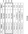
- FIG.4A shows an example of data records recorded in the graph database
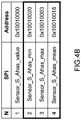
- FIG.4B shows an example of memory addresses for objects of respective data records
- FIG.5A shows steps performed by the graph database management system for storing data records in the graph database
- FIG.5B shows steps performed by the graph database management system for updating an object value of a data record
- FIG.5C shows steps performed by the graph database management system for deleting a data records from the graph database.
- a graph database stores 511 data 310 in the form of data records, for example, triples.
- the data 310 is represented in the form of data records and then serialized by a data serialized 320, i.e. converted to a format that allows the database management system to store the data in its memory 330.
- memory addresses are derived 512 of the objects, i.e. the location in the memory where the objects are stored is derived.
- the memory architecture may comprise a cache memory 331 and a main memory storage 332.
- the graph database management system 130 retrieves the memory addresses in the cache, c_adr, and the memory address in the main memory, m_adr, respectively. If the object is stored directly in the main memory, then its corresponding memory address in the main memory, m_adr, is only derived. Next, the derived memory address is associated 513 with the object and stored 514 in the memory, in the form of a look-up table, LUT, 350.
- each data record is associated with one or more indexes.
- indexes for the subject-predicate pair, SPi, and predicate-subject pair, PSi are derived.
- the SPi and PSi indexes are unique identifiers that allow fast data read when querying data from the graph database. Typically, they are derived by concatenating in a corresponding order the subject and the predicate of a respective data record.
- the memory address is, in effect, associated with the SPi and/or PSi indexes of the respective data records.
- FIG.3B shows a simplified LUT 350 comprising memory addresses m_adr of the main memory 323 associated with the respective SPi indexes of the data records shown in FIG.2A .
- the LUT 350 of FIG.3B is extended to include the cache memory address, c_adr.
- the update 520 of an object value is performed by modifying the object value in the memory.
- the object value stored in the memory of the graph database management system is simply overwritten with its new value.
- the graph database management system 130 retrieves 521 the memory addresses associated with the respective object from the LUT 350 and writes 522 the new object value into the memory address. If the object is stored in either of or in both the cache memory 331 and the main memory storage 332, the respective memory addresses are retrieved, and the new object value is written in the respective memory addresses.
- the system retrieves the index, e.g. SPi index, corresponding to the data record storing the value of the sensor, and then the memory addresses associated to that SPi from the LUT 350.
- the memory address, m_adr, 0x10010000 is retrieved.
- the system writes the new value in the memory address 0x10010000.
- Deleting 530 data from the graph database is performed in a similar way as in the conventional graph database management system.
- the entries in the LUT corresponding to the deleted objects need to be deleted as well.
- the graph database management system deletes 531 the data from the respective memory, i.e. cache memory and main memory, and updates 532 the LUT by deleting the entries of the deleted objects from the LUT 350.
- FIG.4A shows another example embodiment according to the present disclosure according to which additional data records are recorded in the graph database.
- These data records record one or more parameters of a model according to which an object value of a dynamic data record may be modelled.
- the model may be a range-bound specified by a minimum and a maximum CO2 level.
- a new CO2 level will be recorded in the graph database, i.e. the object value of the data record 410 will be updated, only if the latest CO2 level changes from a value within the range bounds to a value outside the range-bound, and, vice versa.
- the system 130 before updating the value of the CO2 sensor in the database, the system 130 performs a query to retrieve the min and max values for this sensor. It then evaluated whether the new object value is out of the range defined by the minimum and maximum values. For example, if the new value is 50, the system will retrieve the memory address for that data record from the LUT 350 and write the new value at that location in the memory.
- the range-bound is recorded as data records 420 and 430; the first data record 420 recording the minimum value of the range and the second data record 430 the maximum value of the range.
- the model may include statistical information such as a mean value of the CO2 level, which may be recorded as another the data record 440 as shown in the figure.
- the model may be pre-determined based on the specifics of the sensor and the environment where the sensor is located.
- the minimum and maximum CO2 levels of the range may be determined based on the size of the room. If the room is an office room configured to seat two people, the min range may be pre-set to a CO2 level signifying that the room is empty and the max range may be pre-set to a CO2 level signify that the room is occupied by more than two people. Thus, if the actual CO2 level is below the max value, an alarm may be issued that the room is occupied by more than two people.
- the model may be derived by means of machine learning.
- the processing device 140 may be configured to train a learning model based on the CO2 levels measured by the respective sensors in the sensor network 100. Once the learning model is trained, the parameters of the trained model are stored in the graph database as data records for the respective sensors.
- the graph database may store data about the people entering the building 110. This may be achieved by storing the number of badge-in and badge-out entries of a badge reader installed at the main entrance of the building 110. Similarly, to the range-bound for the CO2 level, herein a model may be used to issue an alarm if the number of people within the building exceeds a pre-determined limit. The pre-determined limit may be recorded as a separate data record.
- the models recorded as data records in the graph database may be as simple as a min-max model or as complex as a weight matrix derived by means of machine learning.
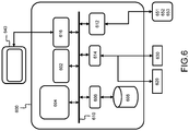
- FIG.6 shows a suitable computing system 600 enabling the implementation of embodiments of the method for manipulating data in a graph database management system according to the present disclosure.
- Computing system 600 may in general be formed as a suitable general-purpose computer and comprise a bus 610, a processor 602, a local memory 604, one or more optional input interfaces 614, one or more optional output interfaces 616, a communication interface 612, a storage element interface 606, and one or more storage elements 608.
- Bus 610 may comprise one or more conductors that permit communication among the components of the computing system 600.
- Processor 602 may include any type of conventional processor or microprocessor that interprets and executes programming instructions.
- Local memory 604 may include a random-access memory, RAM, or another type of dynamic storage device that stores information and instructions for execution by processor 602 and/or a read-only memory, ROM, or another type of static storage device that stores static information and instructions for use by processor 602.
- Input interface 614 may comprise one or more conventional mechanisms that permit an operator or user to input information to the computing device 600, such as a keyboard 620, a mouse 630, a pen, voice recognition and/or biometric mechanisms, a camera, etc.
- Output interface 616 may comprise one or more conventional mechanisms that output information to the operator or user, such as a display 640, etc.
- Communication interface 612 may comprise any transceiver-like mechanism such as for example one or more Ethernet interfaces that enables computing system 600 to communicate with other devices and/or systems, for example with other computing devices 651, 652, 653.
- the communication interface 612 of computing system 600 may be connected to such another computing system by means of a local area network, LAN, or a wide area network, WAN, such as for example the internet.
- Storage element interface 606 may comprise a storage interface such as for example a Serial Advanced Technology Attachment, SATA, interface or a Small Computer System Interface, SCSI, for connecting bus 610 to one or more storage elements 608, such as one or more local disks, for example SATA disk drives, and control the reading and writing of data to and/or from these storage elements 608.
- computing system 600 could thus correspond to the graph database management system as illustrated in FIG.1 and FIG.3 .
- circuitry may refer to one or more or all of the following:
- circuitry also covers an implementation of merely a hardware circuit or processor (or multiple processors) or portion of a hardware circuit or processor and its (or their) accompanying software and/or firmware.
- circuitry also covers, for example and if applicable to the particular claim element, a baseband integrated circuit or processor integrated circuit for a mobile device or a similar integrated circuit in a server, a cellular network device, or other computing or network device.
- top, bottom, over, under, and the like are introduced for descriptive purposes and not necessarily to denote relative positions. It is to be understood that the terms so used are interchangeable under appropriate circumstances and embodiments of the invention are capable of operating according to the present invention in other sequences, or in orientations different from the one(s) described or illustrated above.
Landscapes
- Engineering & Computer Science (AREA)
- Theoretical Computer Science (AREA)
- Databases & Information Systems (AREA)
- Data Mining & Analysis (AREA)
- Physics & Mathematics (AREA)
- General Engineering & Computer Science (AREA)
- General Physics & Mathematics (AREA)
- Software Systems (AREA)
- Information Retrieval, Db Structures And Fs Structures Therefor (AREA)
Abstract
Description
- Various example embodiments relate to a graph database management system and to a method for manipulating data in a graph database management system.
- Graph databases use graph structures such as nodes and edges to represent and store a vast amount of slowly changing connected data, such as a music database. Graph databases use an entity-relationship model that describes how nodes are interconnected or related. According to the entity-relationship model, each node represents an entity such as a parameter, and each edge represents a connection or relation between different parameters. Data is thus represented and stored in the form of data records characterizing the relationship between the different entities.
- Conventional graph databases are optimized either for querying or for writing data into the database. If the database is optimized for data querying, i.e. for reading data, the data writing becomes slow, and vice versa. Thus, the implementation of the graph database is driven by the specific requirements of its use case.
- Recently, graph databases are gaining popularity in new application domains such as sensor networks where millions of sensors are sensing data at a very high frequency, for example, every few seconds. A sensor network may be configured to count the people entering and exiting, to count the cars entering and exiting a parking lot, or it may even be integrated in a traffic control infrastructure to count the cars before a traffic light. In such applications, the ability of the graph databases to handle fast-changing, highly dynamic data becomes crucial.
- Amongst others, it is an object of embodiments of the present disclosure to provide a graph database management system that enables storing highly dynamic data in graph databases without modifying the manner in which data is stored and queried in the graph database management system. It is a further object of embodiments of the present disclosure to provide a graph database management system optimized for both for data querying and data writing.
- The scope of protection sought for various embodiments of the invention is set out by the independent claims.
- The embodiments and features described in this specification that do not fall within the scope of the independent claims, if any, are to be interpreted as examples useful for understanding various embodiments of the invention.
- This object is achieved, according to a first example aspect of the present disclosure, by a graph database management system, comprising at least one processor and at least one memory including computer program code, the at least one memory and computer program code configured, with the at least one processor, to perform storing, in the memory, data in the form of data records in accordance with an entity-relationship model, the data records comprising at least a subject, a predicate, and an object, the database management system being further configured to perform:
- deriving memory addresses of respective objects stored in the memory;
- associating the memory addresses with the respective objects; and
- storing, in the memory, the memory addresses associated with the respective objects.
- In other words, the graph database management system stores the data in its memory in the form of data records in accordance with the entity-relationship model. An example of an entity-relationship model is the Resource Description Framework, RDF, data model. The RDF data model describes the data in the form of subject-predicate-object expression, known as triples. According to the RDF model, the subject defines an entity, the object defines either an entity or a value, and, the predicate defines the relation between them. For example, the information that "Sensor S_A is a CO2 sensor" and that "Sensor S_A has a value of 1000ppm", may be recorded as two triples. The first triple will have a subject denoting "Sensor S_A", a predicate denoting "is a" and an object denoting the entity "CO2 sensor", and the second triple will have a subject denoting "Sensor S_A", a predicate denoting "has a value of" and an object denoting the value "1000 ppm".
- In addition to the subject, predicate and object, a data records may further contain additional fields such as time, a higher-level grouping concept of triples, etc. The higher-level grouping concept of triples may be for example a subgraph unique identifier.
- In addition to storing the data in the memory, the graph database management system stores the memory address of the object. For this purpose, the database management system is configured to derive the memory address of the respective object, i.e. the location in the memory where the value of the respective object is stored.
- The memory may comprise a cache memory for short term storage and a main memory for long term storage such as a hard disk. The cache memory may comprise one or more cache levels, for example, two or even three levels. The different cache levels are commonly referred to as L1, L2 and L3 levels. A data record thus may be stored in the main memory or in both the cache, for example at one or more cache levels and the main memory. Thus, the memory address for the main memory or memory addresses for both the cache and the main memory may be derived depending on where the object is stored.
- The derived memory address is then associated with the respective object and the information is stored in the memory.
- By associating the memory address indicating the storage location of the object in the memory, the object value of the data record may be updated by overwriting the old value stored at the memory address with the new one. As a result, a fast update of the object's value in the graph database management system is enabled. This in turn enables the graph database management system to store and manage highly dynamic data in the graph database without modifying the manner in which data is stored in and queried from the graph database. Thus, a solution applicable to different implementations of graph databases is provided.
- According to example embodiments, the associating comprises: determining unique identifiers for the respective objects; and associating the memory addresses with the respective unique identifiers; and wherein the storing comprises storing the memory addresses and the respective unique identifiers in the form of a lookup table.
- In other words, when storing data in the graph database, the graph database management system determines unique identifiers for the respective data records. The unique identifiers are then associated with the memory addresses of the respective objects. This information, i.e. the unique identifiers together with the associated memory addresses is recorded in the memory of the graph database management system. For example, the information is stored in the form of a look-up table.
- According to example embodiments, the respective objects have a value varying over time.
- Depending on how fast the object value changes over time, data records may be classified as static or dynamic. Static data records are characterized by a constant object value, while dynamic data records are characterized by an object's value varying over time. Depending on the frequency of variation, dynamic data records may be further classified as slowly varying, i.e. less dynamic, or a fast varying, i.e. highly dynamic, data.
- Storing the memory addresses associated with objects of dynamic data records allows limiting the amount of additional data stored in the memory and therefore minimizing the overall memory overhead.
- According to example embodiments, the graph database management system is further configured to perform, when storing, in the memory, a new data record having an object with a varying over time value:
- storing, in the memory, the new data record;
- deriving a memory address of the object of the new data record; and
- storing, in the memory, the memory address associated with the object.
- When storing new data records in the memory, i.e. when additional data is added, the graph database management system stores the new data records in the memory together with the one or memory addresses associated with the objects of the respective new data records. Depending on where the object is stored, the memory address for the main memory or memory addresses for both the cache and the main memory may be derived.
- According to example embodiments, the graph database management system is further configured to perform, when deleting, from the memory, a data record having an object with a varying over time value:
- deleting, from the memory, the data record; and
- deleting, from the memory, the memory address associated with the object.
- When deleting data records from the graph database management system, apart from deleting the data records from the memory, the memory addresses associated with the objects of the respective data records are deleted as well.
- According to example embodiments, the graph database management system is further configured to perform, when updating a value of a respective object:
- retrieving, from the memory, the memory address associated with the respective object; and
- writing a new value to the memory address associated with the respective object.
- A data record may be stored in the main memory or in both the cache and the main memory. Thus, when updating an object value in the graph database, the graph database management system retrieves the one or more memory addresses associated with the respective object. This may be done by retrieving the memory addresses associated with the unique identifier of the data record of the object.
- According to example embodiments, the graph database management system is further configured to perform:
- querying and checking a condition associated with a respective object; and
- updating the value of the respective object if the condition is satisfied.
- In other words, an object value will be updated if a specific condition is satisfied. The condition may be stored in the memory in the form of data records. The condition may thus be retrieved by issuing a query for that condition. The graph database management system will then check whether the new object value satisfies the condition and if so, it will update, i.e. write, the new value in the one or more memory addresses associated with the respective object.
- This allows further limiting the number of writes in the memory and therefore optimizing the write performance of the graph database management system.
- According to example embodiments, wherein the condition implements a threshold or a range-bound.
- Different conditions may be implemented. For example, a condition may be a threshold or a range-bound of the object value. The range-bound may be defined by a minimum and a maximum value. The minimum and maximum values may be derived from object values observed over a period of time, i.e. a time series. The stored object value may thus be updated only if the new object value does not fall within the range-bound defined by the minimum and maximum values. This significantly reduces the write frequency while allowing to keep a usable model of the time series, i.e. in the form of a range-bound, in the graph database.
- According to a second example aspect, a method is disclosed comprising
- storing, in a memory, data in the form of data records in accordance with an entity-relationship model, the data records comprising at least a subject, a predicate, and an object;
- deriving memory addresses of respective objects stored in the memory;
- associating the memory addresses with the respective objects; and
- storing, in the memory, the memory addresses associated with the respective objects.
- According to example embodiments, the associating comprises: determining unique identifiers for the respective objects; and associating the memory addresses with the respective unique identifiers; and wherein the storing comprises storing the memory addresses and the respective unique identifiers in the form of a lookup table.
- According to example embodiments, the respective objects have a value varying over time.
- According to example embodiments, the method is further configured to perform, when updating a value of a respective object:
- retrieving, from the memory, the memory address associated with the respective object; and
- writing a new value to the memory address associated with the respective object.
- According to example embodiments, the method is further configured to perform:
- querying and checking a condition associated with a respective object; and
- updating the value of the respective object if the condition is satisfied.
- The other example embodiments of the first example aspect may further be applied as example embodiments to the second example aspects.
- According to a third example aspect, a computer program product is disclosed comprising computer-executable instructions for performing the following steps when the program is run on a computer:
- storing, in a memory, data in the form of data records in accordance with an entity-relationship model, the data records comprising at least a subject, a predicate, and an object;
- deriving memory addresses of respective objects stored in the memory;
- associating the memory addresses with the respective objects; and
- storing, in the memory, the memory addresses associated with the respective objects.
- The other example embodiments of the first example aspect may be applied as example embodiments to the second example aspect.
- According to a fourth example aspect, a computer readable storage medium is disclosed comprising computer-executable instructions for performing the following steps when the program is run on a computer:
- storing, in a memory, data in the form of data records in accordance with an entity-relationship model, the data records comprising at least a subject, a predicate, and an object;
- deriving memory addresses of respective objects stored in the memory;
- associating the memory addresses with the respective objects; and
- storing, in the memory, the memory addresses associated with the respective objects.
- The various example embodiments of the first example aspect may be applied as example embodiments to the third and fourth example aspects.
- Some example embodiments will now be described with reference to the accompanying drawings.
-
FIG.1 shows an example embodiment of a graph database management system for storing data obtained by a sensor network; -
FIG.2A shows an example of data represented in the form of data records; -
FIG.2B shows a graph representation of the data records ofFIG.2A ; -
FIG.3A shows an example embodiment of a block scheme of the graph database management system according to the present disclosure; -
FIG.3B shows an example of a look-up table according to the present disclosure storing the memory addresses of the data records; -
FIG.4A shows an example of static and dynamic data records according to the present disclosure; -
FIG.4B shows an example of a look-up table according to the present disclosure storing the memory addresses of the dynamic data records ofFIG.4A ; -
FIG.5A shows steps according to an example embodiment of the present disclosure for storing data in a graph database; -
FIG.5B shows steps according to an example embodiment of the present disclosure for updating data in a graph database; -
FIG.5C shows steps according to an example embodiment of the present disclosure for deleting data in a graph database; and -
FIG.6 shows an example embodiment of a suitable computing system for performing one or several steps in embodiments of the invention. - A graph database stores data or information in the form of data records. The data records are created based on an entity-relationship model. An example of an entity-relationship model is the Resource Description Framework, RDF, data model. The RDF data model describes the data in the form of subject-predicate-object expression, known as triples. The subject denotes the resource, the predicate denotes properties or aspects of the resource with a value denoted in the object, or, expresses a relationship between the subject and the object when the object denotes another resource. Graph databases can be optimized either for querying, i.e. for reading data, or for writing data into the database. If the database is optimized for data querying, the data writing becomes slow, and vice versa.
- The present disclosure discloses a graph database management system optimized both for querying and storing data and more specifically of highly dynamic data in the graph database, while preserving the manner in which data is stored in and queried from the graph database.
-
FIG.1 shows awireless sensor network 100 comprising N sensors deployed in several different locations within an environment. The sensors monitor and record the physical conditions of the environment such as temperature, pollution levels, humidity, etc. The recorded information is then collected at a centralized location. In this figure, a wireless sensor network is deployed in an office building to monitor the air quality as well as the number of people occupying the office building. The sensor network comprises sixCO2 sensors 121 to 126 deployed in different rooms of thebuilding 110.Sensors room 111,sensors room 114 andsensors rooms - The sensors record the CO2 level at a high frequency, for example, every 10 sec. The recorded CO2 levels are transmitted to the graph
database management system 130 via awireless channel 131. The graphdatabase management system 130 thus receives a sensed CO2 level from a respective sensor at the frequency of 10 sec. - To monitor the air quality as well as the number of people occupying the rooms, the graph
database management system 130 records a structural representation of the wireless sensor network as well as a characterization of the sensors. This information is stored in the form of data records, for example in the form of triples. -
FIG.2A shows the data records related to theCO2 sensor 121 stored in the graph database. Adata record 200 comprises a subject 210, apredicate 220, and anobject 230, where the subject and the object define two entities and the predicate the relation between them. The first data record in the table records that the sensor "S_A" has a value of "100". In this example, thevalue 100 is denoted in implicit units. In practive this value may correspond to a real CO2 measurement of 20ppm.The second data record in the table records that the sensor "S_A" is a CO2 sensor. The third data record records that the sensor "S_A" is located in the room "R_A". The fourth records that the room "R_A" is a meeting room and the fifth data record records that the room "R_A" is located in building "B_A". This way complete characterization of the wireless sensor network and the environment where the sensor is deployed is stored in the graph database. - This information may be visually represented in the form of a graph as shown in
FIG.2B , where thesubjects 210 and theobjects 230 are the nodes of the graph, represented as circles, and thepredicates 220 are the connections between the graph nodes. - Thus, based on the CO2 level recorded by a specific sensor the graph
database management system 130 may alert that the air quality in a specific room is above or below a pre-determined limit and/or that a specific room is empty or occupied by one, two or more people. - This may be performed by processing the recorded CO2 levels in a
processing device 140. For this purpose, the processing device retrieves the CO2 levels of the respective sensors by querying or reading the objects' values of the respective sensors from the graph database, processes the retrieved values to estimate the room occupation and potentially issues an alert if the CO2 level of a respective room is higher than the health limit. Theprocessing device 140 may be included in the graph database management system and thus forming part of it. Alternatively, theprocessing device 140 may be external to the graph database management system device. In both cases, theprocessing device 140 is configured to accesses thegraph database 130 via acommunication link 141. - The value of some of the objects in the graph database varies over time. Some may vary with a high frequency, i.e. their value will be modified or updated much more frequently than the value of other objects. For example, the value of the object of the first data record will be replaced or updated every 10 sec with a new sensed CO2 level by the sensor S_A, while the value of the objects of the second to fifth data records remain constant over a very long period of time. They might change only if the sensor is physically moved from one location to another, for example in a different room or even a different building. Thus, data records with objects having a value varying over time are, herein, referred to as a dynamic data record, while data records with objects having a constant value are referred to as a static data record.
- The graph database management system and its operation will be now described in more detail with reference to
FIG.3 ,FIG.4 , andFIG.5 .FIG.3A shows relevant components of the graph database management system;FIG.3B shows an example look-up table storing the memory addresses of the data records' objects;FIG.4A shows an example of data records recorded in the graph database;FIG.4B shows an example of memory addresses for objects of respective data records;FIG.5A shows steps performed by the graph database management system for storing data records in the graph database;FIG.5B shows steps performed by the graph database management system for updating an object value of a data record, andFIG.5C shows steps performed by the graph database management system for deleting a data records from the graph database. - As described above, a
graph database stores 511data 310 in the form of data records, for example, triples. For this purpose, thedata 310 is represented in the form of data records and then serialized by a data serialized 320, i.e. converted to a format that allows the database management system to store the data in itsmemory 330. Once the data is stored in the memory, memory addresses are derived 512 of the objects, i.e. the location in the memory where the objects are stored is derived. Depending on the memory architecture of the graphdatabase management system 130, the memory architecture may comprise acache memory 331 and amain memory storage 332. If the object is stored both in thecache memory 331 and themain memory 332, the graphdatabase management system 130 retrieves the memory addresses in the cache, c_adr, and the memory address in the main memory, m_adr, respectively. If the object is stored directly in the main memory, then its corresponding memory address in the main memory, m_adr, is only derived. Next, the derived memory address is associated 513 with the object and stored 514 in the memory, in the form of a look-up table, LUT, 350. - In practice, when storing data in a graph database, each data record is associated with one or more indexes. For example, indexes for the subject-predicate pair, SPi, and predicate-subject pair, PSi, are derived. The SPi and PSi indexes are unique identifiers that allow fast data read when querying data from the graph database. Typically, they are derived by concatenating in a corresponding order the subject and the predicate of a respective data record. Thus, the memory address is, in effect, associated with the SPi and/or PSi indexes of the respective data records.
-
FIG.3B shows asimplified LUT 350 comprising memory addresses m_adr of the main memory 323 associated with the respective SPi indexes of the data records shown inFIG.2A . In case there are data records stored in thecache memory 331, theLUT 350 ofFIG.3B is extended to include the cache memory address, c_adr. - Differently to conventional graph databases, instead of deleting the complete data record and then storing it again with its new object value, herein the
update 520 of an object value is performed by modifying the object value in the memory. In other words, the object value stored in the memory of the graph database management system is simply overwritten with its new value. To do so, the graphdatabase management system 130 retrieves 521 the memory addresses associated with the respective object from theLUT 350 and writes 522 the new object value into the memory address. If the object is stored in either of or in both thecache memory 331 and themain memory storage 332, the respective memory addresses are retrieved, and the new object value is written in the respective memory addresses. - For example, if a new value recorded by sensor S_A is received by the
database management system 130, the system retrieves the index, e.g. SPi index, corresponding to the data record storing the value of the sensor, and then the memory addresses associated to that SPi from theLUT 350. In this example, the memory address, m_adr, 0x10010000, is retrieved. And, finally, the system writes the new value in the memory address 0x10010000. - Deleting 530 data from the graph database is performed in a similar way as in the conventional graph database management system. Herein, however, apart from deleting data from the graph database, the entries in the LUT corresponding to the deleted objects need to be deleted as well. For this purpose, the graph database management system deletes 531 the data from the respective memory, i.e. cache memory and main memory, and updates 532 the LUT by deleting the entries of the deleted objects from the
LUT 350. -
FIG.4A shows another example embodiment according to the present disclosure according to which additional data records are recorded in the graph database. These data records record one or more parameters of a model according to which an object value of a dynamic data record may be modelled. For the example shown inFIG.1 , the model may be a range-bound specified by a minimum and a maximum CO2 level. According to this min-max model, a new CO2 level will be recorded in the graph database, i.e. the object value of thedata record 410 will be updated, only if the latest CO2 level changes from a value within the range bounds to a value outside the range-bound, and, vice versa. For this purpose, before updating the value of the CO2 sensor in the database, thesystem 130 performs a query to retrieve the min and max values for this sensor. It then evaluated whether the new object value is out of the range defined by the minimum and maximum values. For example, if the new value is 50, the system will retrieve the memory address for that data record from theLUT 350 and write the new value at that location in the memory. - As shown in the figure, the range-bound is recorded as
data records first data record 420 recording the minimum value of the range and thesecond data record 430 the maximum value of the range. Further, the model may include statistical information such as a mean value of the CO2 level, which may be recorded as another thedata record 440 as shown in the figure. - The model may be pre-determined based on the specifics of the sensor and the environment where the sensor is located. The minimum and maximum CO2 levels of the range may be determined based on the size of the room. If the room is an office room configured to seat two people, the min range may be pre-set to a CO2 level signifying that the room is empty and the max range may be pre-set to a CO2 level signify that the room is occupied by more than two people. Thus, if the actual CO2 level is below the max value, an alarm may be issued that the room is occupied by more than two people.
- Alternatively, the model may be derived by means of machine learning. In this case, the
processing device 140 may be configured to train a learning model based on the CO2 levels measured by the respective sensors in thesensor network 100. Once the learning model is trained, the parameters of the trained model are stored in the graph database as data records for the respective sensors. - Additionally, the graph database may store data about the people entering the
building 110. This may be achieved by storing the number of badge-in and badge-out entries of a badge reader installed at the main entrance of thebuilding 110. Similarly, to the range-bound for the CO2 level, herein a model may be used to issue an alarm if the number of people within the building exceeds a pre-determined limit. The pre-determined limit may be recorded as a separate data record. - Depending on the specific requirements, the models recorded as data records in the graph database may be as simple as a min-max model or as complex as a weight matrix derived by means of machine learning.
-
FIG.6 shows asuitable computing system 600 enabling the implementation of embodiments of the method for manipulating data in a graph database management system according to the present disclosure.Computing system 600 may in general be formed as a suitable general-purpose computer and comprise abus 610, aprocessor 602, alocal memory 604, one or more optional input interfaces 614, one or moreoptional output interfaces 616, acommunication interface 612, astorage element interface 606, and one ormore storage elements 608.Bus 610 may comprise one or more conductors that permit communication among the components of thecomputing system 600.Processor 602 may include any type of conventional processor or microprocessor that interprets and executes programming instructions.Local memory 604 may include a random-access memory, RAM, or another type of dynamic storage device that stores information and instructions for execution byprocessor 602 and/or a read-only memory, ROM, or another type of static storage device that stores static information and instructions for use byprocessor 602.Input interface 614 may comprise one or more conventional mechanisms that permit an operator or user to input information to thecomputing device 600, such as akeyboard 620, amouse 630, a pen, voice recognition and/or biometric mechanisms, a camera, etc.Output interface 616 may comprise one or more conventional mechanisms that output information to the operator or user, such as adisplay 640, etc.Communication interface 612 may comprise any transceiver-like mechanism such as for example one or more Ethernet interfaces that enablescomputing system 600 to communicate with other devices and/or systems, for example withother computing devices communication interface 612 ofcomputing system 600 may be connected to such another computing system by means of a local area network, LAN, or a wide area network, WAN, such as for example the internet.Storage element interface 606 may comprise a storage interface such as for example a Serial Advanced Technology Attachment, SATA, interface or a Small Computer System Interface, SCSI, for connectingbus 610 to one ormore storage elements 608, such as one or more local disks, for example SATA disk drives, and control the reading and writing of data to and/or from thesestorage elements 608. Although the storage element(s) 608 above is/are described as a local disk, in general any other suitable computer-readable media such as a removable magnetic disk, optical storage media such as a CD or DVD, - ROM disk, solid state drives, flash memory cards, ... could be used.Computing system 600 could thus correspond to the graph database management system as illustrated inFIG.1 andFIG.3 . - As used in this application, the term "circuitry" may refer to one or more or all of the following:
- (a) hardware-only circuit implementations such as implementations in only analog and/or digital circuitry and
- (b) combinations of hardware circuits and software, such as (as applicable):
- (i) a combination of analog and/or digital hardware circuit(s) with software/firmware and
- (ii) any portions of hardware processor(s) with software (including digital signal processor(s)), software, and memory(ies) that work together to cause an apparatus, such as a mobile phone or server, to perform various functions) and
- (c) hardware circuit(s) and/or processor(s), such as microprocessor(s) or a portion of a microprocessor(s), that requires software (e.g. firmware) for operation, but the software may not be present when it is not needed for operation.
- This definition of circuitry applies to all uses of this term in this application, including in any claims. As a further example, as used in this application, the term circuitry also covers an implementation of merely a hardware circuit or processor (or multiple processors) or portion of a hardware circuit or processor and its (or their) accompanying software and/or firmware. The term circuitry also covers, for example and if applicable to the particular claim element, a baseband integrated circuit or processor integrated circuit for a mobile device or a similar integrated circuit in a server, a cellular network device, or other computing or network device.
- Although the present invention has been illustrated by reference to specific embodiments, it will be apparent to those skilled in the art that the invention is not limited to the details of the foregoing illustrative embodiments, and that the present invention may be embodied with various changes and modifications without departing from the scope thereof. The present embodiments are therefore to be considered in all respects as illustrative and not restrictive, the scope of the invention being indicated by the appended claims rather than by the foregoing description, and all changes which come within the scope of the claims are therefore intended to be embraced therein.
- It will furthermore be understood by the reader of this patent application that the words "comprising" or "comprise" do not exclude other elements or steps, that the words "a" or "an" do not exclude a plurality, and that a single element, such as a computer system, a processor, or another integrated unit may fulfil the functions of several means recited in the claims. Any reference signs in the claims shall not be construed as limiting the respective claims concerned. The terms "first", "second", third", "a", "b", "c", and the like, when used in the description or in the claims are introduced to distinguish between similar elements or steps and are not necessarily describing a sequential or chronological order. Similarly, the terms "top", "bottom", "over", "under", and the like are introduced for descriptive purposes and not necessarily to denote relative positions. It is to be understood that the terms so used are interchangeable under appropriate circumstances and embodiments of the invention are capable of operating according to the present invention in other sequences, or in orientations different from the one(s) described or illustrated above.
Claims (15)
- A graph database management system comprising at least one processor (602) and at least one memory (604) including computer program code, the at least one memory and computer program code configured, with the at least one processor, to perform storing (511), in the memory, data in the form of data records in accordance with an entity-relationship model, the data records comprising at least a subject, a predicate, and an object, the database management system being further configured to perform:- deriving (512) memory addresses of respective objects stored in the memory;- associating (513) the memory addresses with the respective objects; and- storing (514), in the memory, the memory addresses associated with the respective objects.
- The graph database management system according to claim 1, wherein the associating comprises: determining unique identifiers for the respective objects; and associating the memory addresses with the respective unique identifiers; and wherein the storing comprises storing the memory addresses and the respective unique identifiers in the form of a lookup table.
- The graph database management system according to claims 1 or 2, wherein the respective objects have a value varying over time.
- The graph database management system according to any one of the preceding claims, further configured to perform, when storing (510), in the memory, a new data record having an object with a varying over time value:- storing (511), in the memory, the new data record;- deriving (512) a memory address of the object of the new data record; and- storing (514), in the memory, the memory address associated with the object.
- The graph database management system according to any one of the preceding claims, further configured to perform, when deleting (530), from the memory, a data record having an object with a varying over time value:- deleting (531), from the memory, the data record; and- deleting (532), from the memory, the memory address associated with the object.
- The graph database management system according to any one of the preceding claims, further configured to perform, when updating (520) a value of a respective object:- retrieving (521), from the memory, the memory address associated with the respective object; and- writing (522) a new value to the memory address associated with the respective object.
- The graph database management system according to any one of the preceding claims further configured to perform :- querying and checking a condition associated with a respective object; and- updating the value of the respective object if the condition is satisfied.
- The graph database management system according to claim 7, wherein the condition implements a threshold or a range-bound.
- A method comprising:- storing (511), in a memory (604), data in the form of data records in accordance with an entity-relationship model, the data records comprising at least a subject, a predicate, and an object;- deriving (512) memory addresses of respective objects stored in the memory;- associating (513) the memory addresses with the respective objects; and- storing (514), in the memory, the memory addresses associated with the respective objects.
- The method according to claim 9, wherein the associating comprises: determining unique identifiers for the respective objects; and associating the memory addresses with the respective unique identifiers; and wherein the storing comprises storing the memory addresses and the respective unique identifiers in the form of a lookup table.
- The method according to claims 9 or 10, wherein the respective objects have a value varying over time.
- The method according to any one of claims 9 to 11, further configured to perform, when updating (520) a value of a respective object:- retrieving (521), from the memory, the memory address associated with the respective object; and- writing (522) a new value to the memory address associated with the respective object.
- The method according to any one of claims 9 to 12, further configured to perform:- querying and checking a condition associated with a respective object; and- updating the value of the respective object if the condition is satisfied.
- A computer program product comprising computer-executable instructions for performing the following steps when the program is run on a computer:- storing (511), in a memory (604), data in the form of data records in accordance with an entity-relationship model, the data records comprising at least a subject, a predicate, and an object;- deriving (512) memory addresses of respective objects stored in the memory;- associating (513) the memory addresses with the respective objects; and- storing (514), in the memory, the memory addresses associated with the respective objects.
- A computer readable storage medium comprising computer-executable instructions for performing the following steps when the program is run on a computer:- storing (511), in a memory (604), data in the form of data records in accordance with an entity-relationship model, the data records comprising at least a subject, a predicate, and an object;- deriving (512) memory addresses of respective objects stored in the memory;- associating (513) the memory addresses with the respective objects; and- storing (514), in the memory, the memory addresses associated with the respective objects.
Priority Applications (1)
| Application Number | Priority Date | Filing Date | Title |
|---|---|---|---|
| EP20182082.6A EP3929761B1 (en) | 2020-06-24 | 2020-06-24 | A graph database management system |
Applications Claiming Priority (1)
| Application Number | Priority Date | Filing Date | Title |
|---|---|---|---|
| EP20182082.6A EP3929761B1 (en) | 2020-06-24 | 2020-06-24 | A graph database management system |
Publications (2)
| Publication Number | Publication Date |
|---|---|
| EP3929761A1 true EP3929761A1 (en) | 2021-12-29 |
| EP3929761B1 EP3929761B1 (en) | 2024-04-03 |
Family
ID=71143591
Family Applications (1)
| Application Number | Title | Priority Date | Filing Date |
|---|---|---|---|
| EP20182082.6A Active EP3929761B1 (en) | 2020-06-24 | 2020-06-24 | A graph database management system |
Country Status (1)
| Country | Link |
|---|---|
| EP (1) | EP3929761B1 (en) |
Cited By (1)
| Publication number | Priority date | Publication date | Assignee | Title |
|---|---|---|---|---|
| CN115904487A (en) * | 2022-11-29 | 2023-04-04 | 广发银行股份有限公司 | Analytical data aperture management method, system, equipment and storage medium |
Citations (2)
| Publication number | Priority date | Publication date | Assignee | Title |
|---|---|---|---|---|
| WO2018080560A1 (en) * | 2016-10-28 | 2018-05-03 | Microsoft Technology Licensing, Llc | Encoding edges in graph databases |
| CN110096515A (en) * | 2019-05-10 | 2019-08-06 | 天津大学深圳研究院 | A kind of RDF data management method, device and storage medium based on triple |
-
2020
- 2020-06-24 EP EP20182082.6A patent/EP3929761B1/en active Active
Patent Citations (2)
| Publication number | Priority date | Publication date | Assignee | Title |
|---|---|---|---|---|
| WO2018080560A1 (en) * | 2016-10-28 | 2018-05-03 | Microsoft Technology Licensing, Llc | Encoding edges in graph databases |
| CN110096515A (en) * | 2019-05-10 | 2019-08-06 | 天津大学深圳研究院 | A kind of RDF data management method, device and storage medium based on triple |
Cited By (2)
| Publication number | Priority date | Publication date | Assignee | Title |
|---|---|---|---|---|
| CN115904487A (en) * | 2022-11-29 | 2023-04-04 | 广发银行股份有限公司 | Analytical data aperture management method, system, equipment and storage medium |
| CN115904487B (en) * | 2022-11-29 | 2023-08-18 | 广发银行股份有限公司 | Analytical data caliber management method, system, equipment and storage medium |
Also Published As
| Publication number | Publication date |
|---|---|
| EP3929761B1 (en) | 2024-04-03 |
Similar Documents
| Publication | Publication Date | Title |
|---|---|---|
| JP2865500B2 (en) | File storage management method | |
| CN104516894B (en) | Method and apparatus for managing time series databases | |
| CN104765731B (en) | Database inquiry optimization method and apparatus | |
| CN107533507A (en) | According to the data in log-structured managing storage | |
| CN105700819B (en) | Method and system for network data storage | |
| CN113297171A (en) | Database migration method and device and database cluster | |
| US10468061B1 (en) | Indexing zones for storage devices | |
| WO2018097846A1 (en) | Edge store designs for graph databases | |
| CN104268099A (en) | Management data reading and writing method and device | |
| CN105630803A (en) | Method and apparatus for establishing index for document database | |
| WO2022241813A1 (en) | Graph database construction method and apparatus based on graph compression, and related component | |
| CN111753186A (en) | Population screening method, device, equipment and storage medium | |
| CN108205571A (en) | The connection method of key assignments tables of data and device | |
| CN113641659A (en) | Medical characteristic database construction method, device, equipment and storage medium | |
| EP3929761B1 (en) | A graph database management system | |
| CN110018949A (en) | A kind of general journal management method and system based on IPMI protocol | |
| JPH08339318A (en) | Data recording device and data management method | |
| CN112488236B (en) | An integrated unsupervised student behavior clustering method | |
| EP3940572B1 (en) | Data generalization device, data generalization method, and program | |
| CN112989949A (en) | Network scene recognition method, equipment and storage medium | |
| KR100858157B1 (en) | System and method for updating map, storage medium recording method program, user terminal | |
| CN119226554A (en) | Commodity image retrieval method, device, electronic device, and storage medium | |
| CN108197267A (en) | The extensive diagnostic method, apparatus and terminal device of partitions of database table | |
| JPH06103128A (en) | Storage device | |
| CN121233784B (en) | Knowledge Graph Generation Method and System Applied to Building Operation Data Mining |
Legal Events
| Date | Code | Title | Description |
|---|---|---|---|
| PUAI | Public reference made under article 153(3) epc to a published international application that has entered the european phase |
Free format text: ORIGINAL CODE: 0009012 |
|
| STAA | Information on the status of an ep patent application or granted ep patent |
Free format text: STATUS: THE APPLICATION HAS BEEN PUBLISHED |
|
| AK | Designated contracting states |
Kind code of ref document: A1 Designated state(s): AL AT BE BG CH CY CZ DE DK EE ES FI FR GB GR HR HU IE IS IT LI LT LU LV MC MK MT NL NO PL PT RO RS SE SI SK SM TR |
|
| B565 | Issuance of search results under rule 164(2) epc |
Effective date: 20201109 |
|
| STAA | Information on the status of an ep patent application or granted ep patent |
Free format text: STATUS: REQUEST FOR EXAMINATION WAS MADE |
|
| 17P | Request for examination filed |
Effective date: 20220629 |
|
| RBV | Designated contracting states (corrected) |
Designated state(s): AL AT BE BG CH CY CZ DE DK EE ES FI FR GB GR HR HU IE IS IT LI LT LU LV MC MK MT NL NO PL PT RO RS SE SI SK SM TR |
|
| GRAP | Despatch of communication of intention to grant a patent |
Free format text: ORIGINAL CODE: EPIDOSNIGR1 |
|
| STAA | Information on the status of an ep patent application or granted ep patent |
Free format text: STATUS: GRANT OF PATENT IS INTENDED |
|
| INTG | Intention to grant announced |
Effective date: 20231117 |
|
| GRAS | Grant fee paid |
Free format text: ORIGINAL CODE: EPIDOSNIGR3 |
|
| GRAA | (expected) grant |
Free format text: ORIGINAL CODE: 0009210 |
|
| STAA | Information on the status of an ep patent application or granted ep patent |
Free format text: STATUS: THE PATENT HAS BEEN GRANTED |
|
| AK | Designated contracting states |
Kind code of ref document: B1 Designated state(s): AL AT BE BG CH CY CZ DE DK EE ES FI FR GB GR HR HU IE IS IT LI LT LU LV MC MK MT NL NO PL PT RO RS SE SI SK SM TR |
|
| REG | Reference to a national code |
Ref country code: CH Ref legal event code: EP |
|
| REG | Reference to a national code |
Ref country code: DE Ref legal event code: R096 Ref document number: 602020028209 Country of ref document: DE |
|
| REG | Reference to a national code |
Ref country code: IE Ref legal event code: FG4D |
|
| REG | Reference to a national code |
Ref country code: LT Ref legal event code: MG9D |
|
| REG | Reference to a national code |
Ref country code: NL Ref legal event code: MP Effective date: 20240403 |
|
| REG | Reference to a national code |
Ref country code: AT Ref legal event code: MK05 Ref document number: 1673126 Country of ref document: AT Kind code of ref document: T Effective date: 20240403 |
|
| PG25 | Lapsed in a contracting state [announced via postgrant information from national office to epo] |
Ref country code: NL Free format text: LAPSE BECAUSE OF FAILURE TO SUBMIT A TRANSLATION OF THE DESCRIPTION OR TO PAY THE FEE WITHIN THE PRESCRIBED TIME-LIMIT Effective date: 20240403 |
|
| PG25 | Lapsed in a contracting state [announced via postgrant information from national office to epo] |
Ref country code: NL Free format text: LAPSE BECAUSE OF FAILURE TO SUBMIT A TRANSLATION OF THE DESCRIPTION OR TO PAY THE FEE WITHIN THE PRESCRIBED TIME-LIMIT Effective date: 20240403 |
|
| PG25 | Lapsed in a contracting state [announced via postgrant information from national office to epo] |
Ref country code: IS Free format text: LAPSE BECAUSE OF FAILURE TO SUBMIT A TRANSLATION OF THE DESCRIPTION OR TO PAY THE FEE WITHIN THE PRESCRIBED TIME-LIMIT Effective date: 20240803 |
|
| PG25 | Lapsed in a contracting state [announced via postgrant information from national office to epo] |
Ref country code: BG Free format text: LAPSE BECAUSE OF FAILURE TO SUBMIT A TRANSLATION OF THE DESCRIPTION OR TO PAY THE FEE WITHIN THE PRESCRIBED TIME-LIMIT Effective date: 20240403 |
|
| PG25 | Lapsed in a contracting state [announced via postgrant information from national office to epo] |
Ref country code: FI Free format text: LAPSE BECAUSE OF FAILURE TO SUBMIT A TRANSLATION OF THE DESCRIPTION OR TO PAY THE FEE WITHIN THE PRESCRIBED TIME-LIMIT Effective date: 20240403 Ref country code: HR Free format text: LAPSE BECAUSE OF FAILURE TO SUBMIT A TRANSLATION OF THE DESCRIPTION OR TO PAY THE FEE WITHIN THE PRESCRIBED TIME-LIMIT Effective date: 20240403 |
|
| PG25 | Lapsed in a contracting state [announced via postgrant information from national office to epo] |
Ref country code: GR Free format text: LAPSE BECAUSE OF FAILURE TO SUBMIT A TRANSLATION OF THE DESCRIPTION OR TO PAY THE FEE WITHIN THE PRESCRIBED TIME-LIMIT Effective date: 20240704 |
|
| PG25 | Lapsed in a contracting state [announced via postgrant information from national office to epo] |
Ref country code: PT Free format text: LAPSE BECAUSE OF FAILURE TO SUBMIT A TRANSLATION OF THE DESCRIPTION OR TO PAY THE FEE WITHIN THE PRESCRIBED TIME-LIMIT Effective date: 20240805 |
|
| PG25 | Lapsed in a contracting state [announced via postgrant information from national office to epo] |
Ref country code: ES Free format text: LAPSE BECAUSE OF FAILURE TO SUBMIT A TRANSLATION OF THE DESCRIPTION OR TO PAY THE FEE WITHIN THE PRESCRIBED TIME-LIMIT Effective date: 20240403 |
|
| PG25 | Lapsed in a contracting state [announced via postgrant information from national office to epo] |
Ref country code: CZ Free format text: LAPSE BECAUSE OF FAILURE TO SUBMIT A TRANSLATION OF THE DESCRIPTION OR TO PAY THE FEE WITHIN THE PRESCRIBED TIME-LIMIT Effective date: 20240403 |
|
| PG25 | Lapsed in a contracting state [announced via postgrant information from national office to epo] |
Ref country code: AT Free format text: LAPSE BECAUSE OF FAILURE TO SUBMIT A TRANSLATION OF THE DESCRIPTION OR TO PAY THE FEE WITHIN THE PRESCRIBED TIME-LIMIT Effective date: 20240403 |
|
| PG25 | Lapsed in a contracting state [announced via postgrant information from national office to epo] |
Ref country code: PL Free format text: LAPSE BECAUSE OF FAILURE TO SUBMIT A TRANSLATION OF THE DESCRIPTION OR TO PAY THE FEE WITHIN THE PRESCRIBED TIME-LIMIT Effective date: 20240403 |
|
| PG25 | Lapsed in a contracting state [announced via postgrant information from national office to epo] |
Ref country code: LV Free format text: LAPSE BECAUSE OF FAILURE TO SUBMIT A TRANSLATION OF THE DESCRIPTION OR TO PAY THE FEE WITHIN THE PRESCRIBED TIME-LIMIT Effective date: 20240403 |
|
| PG25 | Lapsed in a contracting state [announced via postgrant information from national office to epo] |
Ref country code: PT Free format text: LAPSE BECAUSE OF FAILURE TO SUBMIT A TRANSLATION OF THE DESCRIPTION OR TO PAY THE FEE WITHIN THE PRESCRIBED TIME-LIMIT Effective date: 20240805 Ref country code: PL Free format text: LAPSE BECAUSE OF FAILURE TO SUBMIT A TRANSLATION OF THE DESCRIPTION OR TO PAY THE FEE WITHIN THE PRESCRIBED TIME-LIMIT Effective date: 20240403 Ref country code: NO Free format text: LAPSE BECAUSE OF FAILURE TO SUBMIT A TRANSLATION OF THE DESCRIPTION OR TO PAY THE FEE WITHIN THE PRESCRIBED TIME-LIMIT Effective date: 20240703 Ref country code: LV Free format text: LAPSE BECAUSE OF FAILURE TO SUBMIT A TRANSLATION OF THE DESCRIPTION OR TO PAY THE FEE WITHIN THE PRESCRIBED TIME-LIMIT Effective date: 20240403 Ref country code: IS Free format text: LAPSE BECAUSE OF FAILURE TO SUBMIT A TRANSLATION OF THE DESCRIPTION OR TO PAY THE FEE WITHIN THE PRESCRIBED TIME-LIMIT Effective date: 20240803 Ref country code: HR Free format text: LAPSE BECAUSE OF FAILURE TO SUBMIT A TRANSLATION OF THE DESCRIPTION OR TO PAY THE FEE WITHIN THE PRESCRIBED TIME-LIMIT Effective date: 20240403 Ref country code: GR Free format text: LAPSE BECAUSE OF FAILURE TO SUBMIT A TRANSLATION OF THE DESCRIPTION OR TO PAY THE FEE WITHIN THE PRESCRIBED TIME-LIMIT Effective date: 20240704 Ref country code: FI Free format text: LAPSE BECAUSE OF FAILURE TO SUBMIT A TRANSLATION OF THE DESCRIPTION OR TO PAY THE FEE WITHIN THE PRESCRIBED TIME-LIMIT Effective date: 20240403 Ref country code: ES Free format text: LAPSE BECAUSE OF FAILURE TO SUBMIT A TRANSLATION OF THE DESCRIPTION OR TO PAY THE FEE WITHIN THE PRESCRIBED TIME-LIMIT Effective date: 20240403 Ref country code: CZ Free format text: LAPSE BECAUSE OF FAILURE TO SUBMIT A TRANSLATION OF THE DESCRIPTION OR TO PAY THE FEE WITHIN THE PRESCRIBED TIME-LIMIT Effective date: 20240403 Ref country code: BG Free format text: LAPSE BECAUSE OF FAILURE TO SUBMIT A TRANSLATION OF THE DESCRIPTION OR TO PAY THE FEE WITHIN THE PRESCRIBED TIME-LIMIT Effective date: 20240403 Ref country code: AT Free format text: LAPSE BECAUSE OF FAILURE TO SUBMIT A TRANSLATION OF THE DESCRIPTION OR TO PAY THE FEE WITHIN THE PRESCRIBED TIME-LIMIT Effective date: 20240403 Ref country code: RS Free format text: LAPSE BECAUSE OF FAILURE TO SUBMIT A TRANSLATION OF THE DESCRIPTION OR TO PAY THE FEE WITHIN THE PRESCRIBED TIME-LIMIT Effective date: 20240703 |
|
| REG | Reference to a national code |
Ref country code: DE Ref legal event code: R097 Ref document number: 602020028209 Country of ref document: DE |
|
| PG25 | Lapsed in a contracting state [announced via postgrant information from national office to epo] |
Ref country code: DK Free format text: LAPSE BECAUSE OF FAILURE TO SUBMIT A TRANSLATION OF THE DESCRIPTION OR TO PAY THE FEE WITHIN THE PRESCRIBED TIME-LIMIT Effective date: 20240403 |
|
| PG25 | Lapsed in a contracting state [announced via postgrant information from national office to epo] |
Ref country code: EE Free format text: LAPSE BECAUSE OF FAILURE TO SUBMIT A TRANSLATION OF THE DESCRIPTION OR TO PAY THE FEE WITHIN THE PRESCRIBED TIME-LIMIT Effective date: 20240403 |
|
| PG25 | Lapsed in a contracting state [announced via postgrant information from national office to epo] |
Ref country code: RO Free format text: LAPSE BECAUSE OF FAILURE TO SUBMIT A TRANSLATION OF THE DESCRIPTION OR TO PAY THE FEE WITHIN THE PRESCRIBED TIME-LIMIT Effective date: 20240403 Ref country code: SK Free format text: LAPSE BECAUSE OF FAILURE TO SUBMIT A TRANSLATION OF THE DESCRIPTION OR TO PAY THE FEE WITHIN THE PRESCRIBED TIME-LIMIT Effective date: 20240403 |
|
| PG25 | Lapsed in a contracting state [announced via postgrant information from national office to epo] |
Ref country code: SM Free format text: LAPSE BECAUSE OF FAILURE TO SUBMIT A TRANSLATION OF THE DESCRIPTION OR TO PAY THE FEE WITHIN THE PRESCRIBED TIME-LIMIT Effective date: 20240403 |
|
| PG25 | Lapsed in a contracting state [announced via postgrant information from national office to epo] |
Ref country code: SM Free format text: LAPSE BECAUSE OF FAILURE TO SUBMIT A TRANSLATION OF THE DESCRIPTION OR TO PAY THE FEE WITHIN THE PRESCRIBED TIME-LIMIT Effective date: 20240403 Ref country code: SK Free format text: LAPSE BECAUSE OF FAILURE TO SUBMIT A TRANSLATION OF THE DESCRIPTION OR TO PAY THE FEE WITHIN THE PRESCRIBED TIME-LIMIT Effective date: 20240403 Ref country code: RO Free format text: LAPSE BECAUSE OF FAILURE TO SUBMIT A TRANSLATION OF THE DESCRIPTION OR TO PAY THE FEE WITHIN THE PRESCRIBED TIME-LIMIT Effective date: 20240403 Ref country code: EE Free format text: LAPSE BECAUSE OF FAILURE TO SUBMIT A TRANSLATION OF THE DESCRIPTION OR TO PAY THE FEE WITHIN THE PRESCRIBED TIME-LIMIT Effective date: 20240403 Ref country code: DK Free format text: LAPSE BECAUSE OF FAILURE TO SUBMIT A TRANSLATION OF THE DESCRIPTION OR TO PAY THE FEE WITHIN THE PRESCRIBED TIME-LIMIT Effective date: 20240403 Ref country code: MC Free format text: LAPSE BECAUSE OF FAILURE TO SUBMIT A TRANSLATION OF THE DESCRIPTION OR TO PAY THE FEE WITHIN THE PRESCRIBED TIME-LIMIT Effective date: 20240403 |
|
| REG | Reference to a national code |
Ref country code: CH Ref legal event code: PL |
|
| PLBE | No opposition filed within time limit |
Free format text: ORIGINAL CODE: 0009261 |
|
| STAA | Information on the status of an ep patent application or granted ep patent |
Free format text: STATUS: NO OPPOSITION FILED WITHIN TIME LIMIT |
|
| PG25 | Lapsed in a contracting state [announced via postgrant information from national office to epo] |
Ref country code: LU Free format text: LAPSE BECAUSE OF NON-PAYMENT OF DUE FEES Effective date: 20240624 |
|
| 26N | No opposition filed |
Effective date: 20250106 |
|
| PG25 | Lapsed in a contracting state [announced via postgrant information from national office to epo] |
Ref country code: IE Free format text: LAPSE BECAUSE OF NON-PAYMENT OF DUE FEES Effective date: 20240624 |
|
| PG25 | Lapsed in a contracting state [announced via postgrant information from national office to epo] |
Ref country code: BE Free format text: LAPSE BECAUSE OF NON-PAYMENT OF DUE FEES Effective date: 20240630 Ref country code: CH Free format text: LAPSE BECAUSE OF NON-PAYMENT OF DUE FEES Effective date: 20240630 Ref country code: SI Free format text: LAPSE BECAUSE OF FAILURE TO SUBMIT A TRANSLATION OF THE DESCRIPTION OR TO PAY THE FEE WITHIN THE PRESCRIBED TIME-LIMIT Effective date: 20240403 |
|
| PG25 | Lapsed in a contracting state [announced via postgrant information from national office to epo] |
Ref country code: FR Free format text: LAPSE BECAUSE OF NON-PAYMENT OF DUE FEES Effective date: 20240630 |
|
| REG | Reference to a national code |
Ref country code: BE Ref legal event code: MM Effective date: 20240630 |
|
| PGFP | Annual fee paid to national office [announced via postgrant information from national office to epo] |
Ref country code: DE Payment date: 20250429 Year of fee payment: 6 |
|
| PGFP | Annual fee paid to national office [announced via postgrant information from national office to epo] |
Ref country code: GB Payment date: 20250501 Year of fee payment: 6 |
|
| PG25 | Lapsed in a contracting state [announced via postgrant information from national office to epo] |
Ref country code: SE Free format text: LAPSE BECAUSE OF FAILURE TO SUBMIT A TRANSLATION OF THE DESCRIPTION OR TO PAY THE FEE WITHIN THE PRESCRIBED TIME-LIMIT Effective date: 20240403 |
|
| PG25 | Lapsed in a contracting state [announced via postgrant information from national office to epo] |
Ref country code: CY Free format text: LAPSE BECAUSE OF FAILURE TO SUBMIT A TRANSLATION OF THE DESCRIPTION OR TO PAY THE FEE WITHIN THE PRESCRIBED TIME-LIMIT; INVALID AB INITIO Effective date: 20200624 |
|
| PG25 | Lapsed in a contracting state [announced via postgrant information from national office to epo] |
Ref country code: IT Free format text: LAPSE BECAUSE OF FAILURE TO SUBMIT A TRANSLATION OF THE DESCRIPTION OR TO PAY THE FEE WITHIN THE PRESCRIBED TIME-LIMIT Effective date: 20240403 |
|
| PG25 | Lapsed in a contracting state [announced via postgrant information from national office to epo] |
Ref country code: HU Free format text: LAPSE BECAUSE OF FAILURE TO SUBMIT A TRANSLATION OF THE DESCRIPTION OR TO PAY THE FEE WITHIN THE PRESCRIBED TIME-LIMIT; INVALID AB INITIO Effective date: 20200624 |