EP3929704A1 - Optical reference for inertial drift mitigation - Google Patents
Optical reference for inertial drift mitigation Download PDFInfo
- Publication number
- EP3929704A1 EP3929704A1 EP21181527.9A EP21181527A EP3929704A1 EP 3929704 A1 EP3929704 A1 EP 3929704A1 EP 21181527 A EP21181527 A EP 21181527A EP 3929704 A1 EP3929704 A1 EP 3929704A1
- Authority
- EP
- European Patent Office
- Prior art keywords
- photoreceptors
- leds
- head
- inertial
- tracking system
- Prior art date
- Legal status (The legal status is an assumption and is not a legal conclusion. Google has not performed a legal analysis and makes no representation as to the accuracy of the status listed.)
- Pending
Links
Images


Classifications
-
- G—PHYSICS
- G06—COMPUTING OR CALCULATING; COUNTING
- G06F—ELECTRIC DIGITAL DATA PROCESSING
- G06F3/00—Input arrangements for transferring data to be processed into a form capable of being handled by the computer; Output arrangements for transferring data from processing unit to output unit, e.g. interface arrangements
- G06F3/01—Input arrangements or combined input and output arrangements for interaction between user and computer
- G06F3/011—Arrangements for interaction with the human body, e.g. for user immersion in virtual reality
- G06F3/012—Head tracking input arrangements
-
- G—PHYSICS
- G01—MEASURING; TESTING
- G01S—RADIO DIRECTION-FINDING; RADIO NAVIGATION; DETERMINING DISTANCE OR VELOCITY BY USE OF RADIO WAVES; LOCATING OR PRESENCE-DETECTING BY USE OF THE REFLECTION OR RERADIATION OF RADIO WAVES; ANALOGOUS ARRANGEMENTS USING OTHER WAVES
- G01S5/00—Position-fixing by co-ordinating two or more direction or position line determinations; Position-fixing by co-ordinating two or more distance determinations
- G01S5/16—Position-fixing by co-ordinating two or more direction or position line determinations; Position-fixing by co-ordinating two or more distance determinations using electromagnetic waves other than radio waves
-
- G—PHYSICS
- G06—COMPUTING OR CALCULATING; COUNTING
- G06F—ELECTRIC DIGITAL DATA PROCESSING
- G06F3/00—Input arrangements for transferring data to be processed into a form capable of being handled by the computer; Output arrangements for transferring data from processing unit to output unit, e.g. interface arrangements
- G06F3/01—Input arrangements or combined input and output arrangements for interaction between user and computer
- G06F3/03—Arrangements for converting the position or the displacement of a member into a coded form
- G06F3/0304—Detection arrangements using opto-electronic means
- G06F3/0308—Detection arrangements using opto-electronic means comprising a plurality of distinctive and separately oriented light emitters or reflectors associated to the pointing device, e.g. remote cursor controller with distinct and separately oriented LEDs at the tip whose radiations are captured by a photo-detector associated to the screen
-
- G—PHYSICS
- G06—COMPUTING OR CALCULATING; COUNTING
- G06F—ELECTRIC DIGITAL DATA PROCESSING
- G06F3/00—Input arrangements for transferring data to be processed into a form capable of being handled by the computer; Output arrangements for transferring data from processing unit to output unit, e.g. interface arrangements
- G06F3/01—Input arrangements or combined input and output arrangements for interaction between user and computer
- G06F3/03—Arrangements for converting the position or the displacement of a member into a coded form
- G06F3/0304—Detection arrangements using opto-electronic means
- G06F3/0325—Detection arrangements using opto-electronic means using a plurality of light emitters or reflectors or a plurality of detectors forming a reference frame from which to derive the orientation of the object, e.g. by triangulation or on the basis of reference deformation in the picked up image
Definitions
- Inertial head-tracking systems are compact and low cost, but drift rates over time are inadequate for precision pointing applications.
- Methods for "ground truth reference" are applied on a regular interval to correct drift misalignment.
- Existing methods to correct drift, such as inertial optical blend, require expensive cameras and / or are computationally intensive.
- embodiments of the inventive concepts disclosed herein are directed to a system of light emitting diodes (LEDs) and photoreceptors.
- the LEDs and photoreceptors are positioned around the environment and head worn goggles or helmet respectively.
- a processor periodically receives measurements from the photoreceptors and resets inertial drift based on those measurements.
- either the LEDs or the photoreceptors are constrained to a specified range to allow for more accurate drift estimation.
- inventive concepts are not limited in their application to the details of construction and the arrangement of the components or steps or methodologies set forth in the following description or illustrated in the drawings.
- inventive concepts disclosed herein may be practiced without these specific details.
- well-known features may not be described in detail to avoid unnecessarily complicating the instant disclosure.
- inventive concepts disclosed herein are capable of other embodiments or of being practiced or carried out in various ways. Also, it is to be understood that the phraseology and terminology employed herein is for the purpose of description and should not be regarded as limiting.
- a letter following a reference numeral is intended to reference an embodiment of the feature or element that may be similar, but not necessarily identical, to a previously described element or feature bearing the same reference numeral (e.g., 1, 1a, 1b).
- reference numeral e.g. 1, 1a, 1b
- Such shorthand notations are used for purposes of convenience only, and should not be construed to limit the inventive concepts disclosed herein in any way unless expressly stated to the contrary.
- any reference to "one embodiment,” or “some embodiments” means that a particular element, feature, structure, or characteristic described in connection with the embodiment is included in at least one embodiment of the inventive concepts disclosed herein.
- the appearances of the phrase “in some embodiments” in various places in the specification are not necessarily all referring to the same embodiment, and embodiments of the inventive concepts disclosed may include one or more of the features expressly described or inherently present herein, or any combination of sub-combination of two or more such features, along with any other features which may not necessarily be expressly described or inherently present in the instant disclosure.
- embodiments of the inventive concepts disclosed herein are directed to a pose tracking and verification system for determining poses from fiducials with coded dimensional features. While specific embodiments described herein are directed toward head-tracking systems, the principles described are generally applicable to any system with one or more cameras rigidly affixed to one body and one or more fiducials with coded features rigidly affixed to a second body.
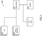
- FIG. 1 a block diagram of a system 100 useful for implanting exemplary embodiments is shown.
- the system 100 embodied in or working in conjunction with an inertial head-tracking system, includes a processor 102, memory 104 in data communication with the processor 102 for embodying processor executable code, a plurality of LEDs 106, and a plurality of photoreceptors 108 in data communication with the processor 102.
- the plurality of LEDs 106 may or may not be in data communication with the processor 102.
- head pose estimates deviate over time.
- the processor 102 is configured to determine a drift correction by periodically receiving values from the photoreceptors 108 corresponding to an intensity of light from the LEDs 106.
- the intensity values generally correspond to more or less direct exposure the LEDs 106.
- Multiple, contemporaneous photoreceptor values may be combined to identify an estimated head pose; the estimated head pose is compared to head pose determined via inertial head-tracking.
- the difference between the estimated head pose and the inertial head-tracking determined pose may comprise a measure of drift.
- a correction factor is determined based on the difference and the correction factor is applied to future inertial head-tracking poses until the next drift determination.
- the processor 102 may receive a head pose from an inertial head-tracking system and determine anticipated photoreceptor intensity values. The anticipated photoreceptor values may be compared to received photoreceptor values to determine a drift correction.
- the LEDs 106 are adapted to operate in a wavelength that is not visible to the human eye to avoid distracting pilots, for night-vision compatibility, for sunlight rejection. Combinations of LEDs 106 and photoreceptors 108 may be adapted to operate in distinct wavelengths such that photoreceptors 108 only register light from one or more specific LEDs 106. Such embodiments may operate with greater accuracy within a limited range of likely head poses.
- each of the LEDs 106 may be configured to flash at a specific frequency such that corresponding photoreceptors 108 may distinguish received intensity values.
- a photoreceptor 108 may periodically register a first intensity at a first frequency; likewise, the same photoreceptor 108 may periodically register a second intensity at a second frequency.
- other photoreceptors 108 may similarly receive intensity values at those frequencies; the disparity in intensity values may be used to triangulate the relative position of each LED 106 with respect to the photoreceptors 108, and thereby produce an estimated head pose.
- the system 100 further comprises a data storage element 110 in data communication with the at least one processor 102.
- the data storage element may store relational values associating photoreceptor values with an estimated head pose.
- An aircraft cockpit 200 utilizing an inertial head-tracking system may include a drift correction system.
- the drift correction system determines drift correction values for head poses of a pilots helmet 202 based on a head pose determined by the inertial head-tracking system and the relative locations of light sources 204, 206 disposed on the helmet 202 with respect to photoreceptors 208, 210, 212 disposed at known locations around the cabin.
- light sources may be disposed about the cabin while the photoreceptors are disposed on the helmet 202.
- existing in cabin light sources may be utilized provided they are sufficiently distinguishable by the corresponding photoreceptors.
- Light sources 204, 206 and photoreceptors 208, 210, 212 may be disposed to substantially isolate specific light source 204, 206 and photoreceptor 208, 210, 212 pairs to limit interference when the helmet 202 is within a range of expected values.
- An aircraft cockpit 300 utilizing an inertial head-tracking system may include a drift correction system.
- the drift correction system determines drift correction values for head poses of multiple pilots' helmets 302, 304 based on head poses determined by the inertial head-tracking system and the relative locations of light sources 306, 308, 310, 312 disposed on the helmets 302, 304 with respect to photoreceptors 314, 316, 318, 320, 322, 324 disposed at known locations around the cabin.
- Light sources 306, 308, 310, 312 may be configured to distinguish a first helmet 302 from a second helmet 304.
- a first set of light sources 306, 308 associated with the first helmet 302 and a second set of light sources 310, 312 associated with the second helmet 304 may be operated exclusively such that the first set of light sources 306, 308 and the second set of light sources 310, 312 are not on at the same time.
- a single set of photoreceptors 314, 316, 318, 320, 322, 324 may thereby identify drift correction values for more than one helmet 302, 304.
- light sources may be disposed about the cabin while the photoreceptors are disposed on the helmets 302, 304.
- existing in cabin light sources may be utilized provided they are sufficiently distinguishable by the corresponding photoreceptors.
- a range restriction element 400 according to an exemplary embodiment is shown. In at least one embodiment, it may be advantageous to restrict the field of view of a photoreceptor 402 to exclude some of a plurality of light sources and enhance the accuracy of the drift correction system.
- a range restriction element 500 according to an exemplary embodiment is shown. In at least one embodiment, it may be advantageous to restrict the field of illumination of a light source 502 to focus light on specific photoreceptors to enhance the accuracy of the drift correction system.
- photoreceptor range restriction elements FIG. 4
- light source range restriction elements FIG. 5
- the helmet 600 comprises a plurality of light sources 602, 604 disposed at locations identified to be easily registered via photoreceptors disposed at known locations in a cockpit, and easily distinguishable from each other.
- the light sources 602, 604 may be disposed to register predictably changing values as a function of head pose; for example, a first light source 602 may produce a linearly diminishing intensity value at a photoreceptor as the helmet turns about a vertical axis, while a second light source 604 may produce a linearly diminishing intensity value at a photoreceptor as the helmet inclines or declines about a vertical axis.
- a pilot may have goggles with embedded light sources 602, 604. Such embodiment may allow for a more compact form while still closely associating the light sources 602, 604 with the pilot's eyes.
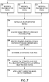
- Photoreceptor signals are received 700, 702, 704 from a plurality of photoreceptors; each signal corresponding to light source intensities.
- the photoreceptor signals are distinguished 706; for example, via separation in time (light sources exclusively operated within millisecond windows), distinct flashing frequencies in each light source, distinct operating wavelength of each light source, etc.
- signal strengths are analyzed 708 and relative locations of each photoreceptor and light source are identified 710.
- the photoreceptors are disposed at known locations and the light sources are disposed relative to each other; in other embodiments, the light sources are disposed at known locations and the photoreceptors are disposed relative to each other.
- locations may be determined via triangulation algorithms specific to the disposition of the elements.
- a neural network algorithm may be trained via associations of photoreceptor values and locations or head poses.
- an estimated head pose is determined 712 based on the identified locations of the elements.
- the estimated head pose is compared 714 to a head pose determined via an inertial head-tracking system.
- the difference of the estimated pose and output of the inertial head tacking system comprises a drift correction factor.
- the drift correction factor is applied 716 to future inertial head poses until the next drift correction factor is determined.
- the method is applied periodically; for example, every ten seconds.
- neural network algorithms may be trained to produce a drift correction based on photoreceptor inputs and inertial head-tracking inputs.
Landscapes
- Engineering & Computer Science (AREA)
- Physics & Mathematics (AREA)
- General Engineering & Computer Science (AREA)
- Theoretical Computer Science (AREA)
- General Physics & Mathematics (AREA)
- Human Computer Interaction (AREA)
- Electromagnetism (AREA)
- Radar, Positioning & Navigation (AREA)
- Remote Sensing (AREA)
- Length Measuring Devices By Optical Means (AREA)
Abstract
Description
- Inertial head-tracking systems are compact and low cost, but drift rates over time are inadequate for precision pointing applications. Methods for "ground truth reference" are applied on a regular interval to correct drift misalignment. Existing methods to correct drift, such as inertial optical blend, require expensive cameras and / or are computationally intensive.
- In one aspect, embodiments of the inventive concepts disclosed herein are directed to a system of light emitting diodes (LEDs) and photoreceptors. The LEDs and photoreceptors are positioned around the environment and head worn goggles or helmet respectively. A processor periodically receives measurements from the photoreceptors and resets inertial drift based on those measurements.
- In a further aspect, either the LEDs or the photoreceptors are constrained to a specified range to allow for more accurate drift estimation.
- It is to be understood that both the foregoing general description and the following detailed description are exemplary and explanatory only and should not restrict the scope of the claims. The accompanying drawings, which are incorporated in and constitute a part of the specification, illustrate exemplary embodiments of the inventive concepts disclosed herein and together with the general description, serve to explain the principles.
- The numerous advantages of the embodiments of the inventive concepts disclosed herein may be better understood by those skilled in the art by reference to the accompanying figures in which:
- FIG. 1
- shows a block diagram of a system useful for implanting exemplary embodiments;
- FIG. 2
- shows a perspective, environmental view according to an exemplary embodiment;
- FIG. 3
- shows a perspective, environmental view according to an exemplary embodiment;
- FIG. 4
- shows a range restriction element according to an exemplary embodiment;
- FIG. 5
- shows a range restriction element according to an exemplary embodiment;
- FIG. 6
- shows a helmet according to an exemplary embodiment;
- FIG. 7
- shows a flowchart for a method of correcting drift according to an exemplary embodiment;
- Before explaining at least one embodiment of the inventive concepts disclosed herein in detail, it is to be understood that the inventive concepts are not limited in their application to the details of construction and the arrangement of the components or steps or methodologies set forth in the following description or illustrated in the drawings. In the following detailed description of embodiments of the instant inventive concepts, numerous specific details are set forth in order to provide a more thorough understanding of the inventive concepts. However, it will be apparent to one of ordinary skill in the art having the benefit of the instant disclosure that the inventive concepts disclosed herein may be practiced without these specific details. In other instances, well-known features may not be described in detail to avoid unnecessarily complicating the instant disclosure. The inventive concepts disclosed herein are capable of other embodiments or of being practiced or carried out in various ways. Also, it is to be understood that the phraseology and terminology employed herein is for the purpose of description and should not be regarded as limiting.
- As used herein a letter following a reference numeral is intended to reference an embodiment of the feature or element that may be similar, but not necessarily identical, to a previously described element or feature bearing the same reference numeral (e.g., 1, 1a, 1b). Such shorthand notations are used for purposes of convenience only, and should not be construed to limit the inventive concepts disclosed herein in any way unless expressly stated to the contrary.
- Further, unless expressly stated to the contrary, "or" refers to an inclusive or and not to an exclusive or. For example, a condition A or B is satisfied by anyone of the following: A is true (or present) and B is false (or not present), A is false (or not present) and B is true (or present), and both A and B are true (or present).
- In addition, use of the "a" or "an" are employed to describe elements and components of embodiments of the instant inventive concepts. This is done merely for convenience and to give a general sense of the inventive concepts, and "a" and "an" are intended to include one or at least one and the singular also includes the plural unless it is obvious that it is meant otherwise.
- Finally, as used herein any reference to "one embodiment," or "some embodiments" means that a particular element, feature, structure, or characteristic described in connection with the embodiment is included in at least one embodiment of the inventive concepts disclosed herein. The appearances of the phrase "in some embodiments" in various places in the specification are not necessarily all referring to the same embodiment, and embodiments of the inventive concepts disclosed may include one or more of the features expressly described or inherently present herein, or any combination of sub-combination of two or more such features, along with any other features which may not necessarily be expressly described or inherently present in the instant disclosure.
- Broadly, embodiments of the inventive concepts disclosed herein are directed to a pose tracking and verification system for determining poses from fiducials with coded dimensional features. While specific embodiments described herein are directed toward head-tracking systems, the principles described are generally applicable to any system with one or more cameras rigidly affixed to one body and one or more fiducials with coded features rigidly affixed to a second body.
- Referring to
FIG. 1 , a block diagram of asystem 100 useful for implanting exemplary embodiments is shown. Thesystem 100, embodied in or working in conjunction with an inertial head-tracking system, includes aprocessor 102,memory 104 in data communication with theprocessor 102 for embodying processor executable code, a plurality ofLEDs 106, and a plurality ofphotoreceptors 108 in data communication with theprocessor 102. The plurality ofLEDs 106 may or may not be in data communication with theprocessor 102. - During inertial head-tracking, head pose estimates deviate over time. In at least one embodiment, the
processor 102 is configured to determine a drift correction by periodically receiving values from thephotoreceptors 108 corresponding to an intensity of light from theLEDs 106. The intensity values generally correspond to more or less direct exposure theLEDs 106. Multiple, contemporaneous photoreceptor values may be combined to identify an estimated head pose; the estimated head pose is compared to head pose determined via inertial head-tracking. The difference between the estimated head pose and the inertial head-tracking determined pose may comprise a measure of drift. A correction factor is determined based on the difference and the correction factor is applied to future inertial head-tracking poses until the next drift determination. - Alternatively, or in addition, the
processor 102 may receive a head pose from an inertial head-tracking system and determine anticipated photoreceptor intensity values. The anticipated photoreceptor values may be compared to received photoreceptor values to determine a drift correction. - In at least one embodiment, the
LEDs 106 are adapted to operate in a wavelength that is not visible to the human eye to avoid distracting pilots, for night-vision compatibility, for sunlight rejection. Combinations ofLEDs 106 andphotoreceptors 108 may be adapted to operate in distinct wavelengths such thatphotoreceptors 108 only register light from one or morespecific LEDs 106. Such embodiments may operate with greater accuracy within a limited range of likely head poses. - In at least one embodiment, each of the
LEDs 106 may be configured to flash at a specific frequency such thatcorresponding photoreceptors 108 may distinguish received intensity values. For example, aphotoreceptor 108 may periodically register a first intensity at a first frequency; likewise, thesame photoreceptor 108 may periodically register a second intensity at a second frequency. Furthermore,other photoreceptors 108 may similarly receive intensity values at those frequencies; the disparity in intensity values may be used to triangulate the relative position of eachLED 106 with respect to thephotoreceptors 108, and thereby produce an estimated head pose. - In at least one embodiment, the
system 100 further comprises adata storage element 110 in data communication with the at least oneprocessor 102. The data storage element may store relational values associating photoreceptor values with an estimated head pose. - Referring to
FIG. 2 , a perspective, environmental view according to an exemplary embodiment is shown. Anaircraft cockpit 200 utilizing an inertial head-tracking system may include a drift correction system. The drift correction system determines drift correction values for head poses of apilots helmet 202 based on a head pose determined by the inertial head-tracking system and the relative locations oflight sources helmet 202 with respect tophotoreceptors - Alternatively, in at least one embodiment, light sources may be disposed about the cabin while the photoreceptors are disposed on the
helmet 202. Furthermore, existing in cabin light sources may be utilized provided they are sufficiently distinguishable by the corresponding photoreceptors. -
Light sources photoreceptors light source photoreceptor helmet 202 is within a range of expected values. - Referring to
FIG. 3 , a perspective, environmental view according to an exemplary embodiment is shown. Anaircraft cockpit 300 utilizing an inertial head-tracking system may include a drift correction system. The drift correction system determines drift correction values for head poses of multiple pilots'helmets 302, 304 based on head poses determined by the inertial head-tracking system and the relative locations oflight sources helmets 302, 304 with respect tophotoreceptors Light sources second helmet 304. For example, a first set oflight sources 306, 308 associated with the first helmet 302 and a second set oflight sources 310, 312 associated with thesecond helmet 304 may be operated exclusively such that the first set oflight sources 306, 308 and the second set oflight sources 310, 312 are not on at the same time. A single set ofphotoreceptors helmet 302, 304. - Alternatively, in at least one embodiment, light sources may be disposed about the cabin while the photoreceptors are disposed on the
helmets 302, 304. Furthermore, existing in cabin light sources may be utilized provided they are sufficiently distinguishable by the corresponding photoreceptors. - Referring to
FIG. 4 , arange restriction element 400 according to an exemplary embodiment is shown. In at least one embodiment, it may be advantageous to restrict the field of view of aphotoreceptor 402 to exclude some of a plurality of light sources and enhance the accuracy of the drift correction system. - Referring to
FIG. 5 , arange restriction element 500 according to an exemplary embodiment is shown. In at least one embodiment, it may be advantageous to restrict the field of illumination of alight source 502 to focus light on specific photoreceptors to enhance the accuracy of the drift correction system. - It may be appreciated that a combination of photoreceptor range restriction elements (
FIG. 4 ) and light source range restriction elements (FIG. 5 ) may be employed. - Referring to
FIG. 6 , ahelmet 600 according to an exemplary embodiment is shown. In at least one embodiment, thehelmet 600 comprises a plurality oflight sources light sources light source 602 may produce a linearly diminishing intensity value at a photoreceptor as the helmet turns about a vertical axis, while a secondlight source 604 may produce a linearly diminishing intensity value at a photoreceptor as the helmet inclines or declines about a vertical axis. - It may be appreciated that, while embodiments are shown depicting
light sources helmet 600, all of the same principles may be applied to a system where the light sources are disposed about the cockpit and the photoreceptors are disposed on thehelmet 600. - It may be appreciated that while embodiments are shown with
light sources helmet 600, other embodiments are envisioned. For example, in at least one embodiment, a pilot may have goggles with embeddedlight sources light sources - Referring to
FIG. 7 , a flowchart for a method of correcting drift according to an exemplary embodiment is shown. Photoreceptor signals are received 700, 702, 704 from a plurality of photoreceptors; each signal corresponding to light source intensities. The photoreceptor signals are distinguished 706; for example, via separation in time (light sources exclusively operated within millisecond windows), distinct flashing frequencies in each light source, distinct operating wavelength of each light source, etc. - Based on the distinguished signals, signal strengths are analyzed 708 and relative locations of each photoreceptor and light source are identified 710. In at least one embodiment, the photoreceptors are disposed at known locations and the light sources are disposed relative to each other; in other embodiments, the light sources are disposed at known locations and the photoreceptors are disposed relative to each other. In at least one embodiment, locations may be determined via triangulation algorithms specific to the disposition of the elements. Alternatively, a neural network algorithm may be trained via associations of photoreceptor values and locations or head poses.
- In at least one embodiment, an estimated head pose is determined 712 based on the identified locations of the elements. The estimated head pose is compared 714 to a head pose determined via an inertial head-tracking system. The difference of the estimated pose and output of the inertial head tacking system comprises a drift correction factor. The drift correction factor is applied 716 to future inertial head poses until the next drift correction factor is determined. In at least one embodiment, the method is applied periodically; for example, every ten seconds.
- In at least one embodiment, neural network algorithms may be trained to produce a drift correction based on photoreceptor inputs and inertial head-tracking inputs.
- It is believed that the inventive concepts disclosed herein and many of their attendant advantages will be understood by the foregoing description of embodiments of the inventive concepts disclosed, and it will be apparent that various changes may be made in the form, construction, and arrangement of the components thereof without departing from the broad scope of the inventive concepts disclosed herein or without sacrificing all of their material advantages; and individual features from various embodiments may be combined to arrive at other embodiments. The form herein before described being merely an explanatory embodiment thereof, it is the intention of the following claims to encompass and include such changes. Furthermore, any of the features disclosed in relation to any of the individual embodiments may be incorporated into any other embodiment.
Claims (15)
- An inertial head-tracking system (100) comprising:a plurality of light emitting diodes "LEDs" (106);a plurality of photoreceptors (108); andat least one processor (102) in data communication with the plurality of photoreceptors (108) and a memory storing processor executable code to configure the at least one processor to:receive a signal from each of the plurality of photoreceptors (108), each signal corresponding to light from one or more of the plurality of LEDs (106) ;determine a relative location of each of the plurality of LEDs (106) and plurality of photoreceptors (108);produce an estimated head pose based on the determined locations;receive a determined head pose based on inertial head-tracking;compare the estimated head pose to the determined head pose; anddetermine a drift correction factor based on the comparison.
- The inertial head-tracking system of Claim 1, wherein the plurality of LEDs and plurality of photoreceptors are configured to operate in a wavelength invisible to a human eye.
- The inertial head-tracking system of any preceding Claim, wherein the plurality of LEDs and plurality of photoreceptors define sets of LEDs and photoreceptors, each set configured to operate in a distinct wavelength.
- The inertial head-tracking system of any preceding Claim, wherein each LED in the plurality of LEDs is configured to flash at a distinct frequency.
- The inertial head-tracking system of any preceding Claim, further comprising a range restriction element associated with each photoreceptor in the plurality of photoreceptors.
- The inertial head-tracking system of any preceding Claim, further comprising a range restriction element associated with each LED in the plurality of LEDs.
- The inertial head-tracking system of any preceding Claim, wherein determining the relative location of each of the plurality of LEDs and plurality of photoreceptors comprises applying a trained neural network algorithm to the signals.
- The inertial head-tracking system of any preceding Claim, wherein the plurality of photoreceptors are disposed at known locations on a helmet.
- The inertial head-tracking system of any preceding Claim, wherein the plurality of LEDs are disposed at known locations on a helmet.
- A method for correcting drift in an inertial head-tracking system comprising:receiving a signal from each of a plurality of photoreceptors (108), each signal corresponding to light from one or more of a plurality of LEDs (106);determining a relative location of each of the plurality of LEDs (106) and plurality of photoreceptors (108);producing an estimated head pose based on the determined locations;receiving a determined head pose based on inertial head-tracking;comparing the estimated head pose to the determined head pose; anddetermining a drift correction factor based on the comparison.
- The method of Claim 10, wherein the plurality of LEDs and plurality of photoreceptors are configured to operate in a wavelength invisible to a human eye.
- The method of Claim 10, wherein the plurality of LEDs and plurality of photoreceptors define sets of LEDs and photoreceptors, each set configured to operate in a distinct wavelength.
- The method of any of Claims 10 to 12, further comprising flashing each LED at a distinct frequency.
- The method of any of Claims 10 to 13, wherein determining the relative location of each of the plurality of LEDs and plurality of photoreceptors comprises applying a trained neural network algorithm to the signals.
- The method of any of Claims 10 to 14, wherein determining the drift correction comprises applying a trained neural network algorithm to the signals and the determined head pose.
Applications Claiming Priority (1)
| Application Number | Priority Date | Filing Date | Title |
|---|---|---|---|
| US16/910,995 US12130374B2 (en) | 2020-06-24 | 2020-06-24 | Optical reference for inertial drift mitigation |
Publications (1)
| Publication Number | Publication Date |
|---|---|
| EP3929704A1 true EP3929704A1 (en) | 2021-12-29 |
Family
ID=76601135
Family Applications (1)
| Application Number | Title | Priority Date | Filing Date |
|---|---|---|---|
| EP21181527.9A Pending EP3929704A1 (en) | 2020-06-24 | 2021-06-24 | Optical reference for inertial drift mitigation |
Country Status (2)
| Country | Link |
|---|---|
| US (1) | US12130374B2 (en) |
| EP (1) | EP3929704A1 (en) |
Families Citing this family (1)
| Publication number | Priority date | Publication date | Assignee | Title |
|---|---|---|---|---|
| JP2026025395A (en) * | 2024-08-02 | 2026-02-16 | 任天堂株式会社 | Stationary Devices |
Citations (8)
| Publication number | Priority date | Publication date | Assignee | Title |
|---|---|---|---|---|
| US5023943A (en) * | 1988-12-31 | 1991-06-11 | Deutsche Itt Industries Gmbh | Electrooptical pointing device for remotely controlling electronic apparatus |
| US6608688B1 (en) * | 1998-04-03 | 2003-08-19 | Image Guided Technologies, Inc. | Wireless optical instrument for position measurement and method of use therefor |
| US20140362370A1 (en) * | 2013-06-11 | 2014-12-11 | Sony Computer Entertainment Europe Limited | Directional light beams for angle detection |
| US20170308159A1 (en) * | 2016-04-26 | 2017-10-26 | Oculus Vr, Llc | Motion Tracker with an Array of Distinct Light Sources |
| US20170352160A1 (en) * | 2016-06-01 | 2017-12-07 | Kyocera Corporation | Detection method, display apparatus, and detection system |
| US20180266847A1 (en) * | 2015-09-11 | 2018-09-20 | Bae Systems Plc | Inertial sensor data correction |
| US20180322335A1 (en) * | 2017-05-07 | 2018-11-08 | Massachusetts Institute Of Technology | Methods and Apparatus for Sharing of Music or Other Information |
| US20190094989A1 (en) * | 2017-09-27 | 2019-03-28 | Htc Corporation | Tracking system, virtual reality system and attachable device |
Family Cites Families (21)
| Publication number | Priority date | Publication date | Assignee | Title |
|---|---|---|---|---|
| JPH10960A (en) | 1996-06-12 | 1998-01-06 | Yazaki Corp | Driver monitoring device |
| US20070273983A1 (en) * | 2006-05-26 | 2007-11-29 | Hebert Raymond T | Devices, methods, and systems for image viewing |
| US7893890B2 (en) | 2007-03-05 | 2011-02-22 | The Boeing Company | Electrically dimmable combiner optics for head-up display |
| US8487837B2 (en) | 2008-11-06 | 2013-07-16 | Bae Systems Information And Electronic Systems Integration Inc. | Optical six-degree of freedom tracking apparatus and method |
| JP5252080B2 (en) * | 2009-06-10 | 2013-07-31 | 株式会社島津製作所 | Head-mounted display device |
| US8825435B2 (en) | 2010-02-19 | 2014-09-02 | Itrack, Llc | Intertial tracking system with provision for position correction |
| EP2428813B1 (en) | 2010-09-08 | 2014-02-26 | Harman Becker Automotive Systems GmbH | Head Tracking System with Improved Detection of Head Rotation |
| US9213084B2 (en) * | 2011-02-24 | 2015-12-15 | The Flewelling Ford Family Trust | Situational marking and awareness tag (SMART) beacon, system and method |
| US9167860B2 (en) * | 2012-01-13 | 2015-10-27 | Craig M. Fedewa | Protective modular helmet with integrated lighting system |
| US11389059B2 (en) * | 2013-01-25 | 2022-07-19 | Wesley W. O. Krueger | Ocular-performance-based head impact measurement using a faceguard |
| WO2014167387A1 (en) | 2013-04-12 | 2014-10-16 | Aselsan Elektronik Sanayi Ve Ticaret Anonim Sirketi | A system and method for optimizing fiducial marker and camera positions/orientations |
| KR101723765B1 (en) | 2013-06-11 | 2017-04-05 | 아셀산 엘렉트로닉 사나이 베 티카렛 아노님 시르케티 | Pose determination from a pattern of four leds |
| US10247613B1 (en) * | 2015-04-03 | 2019-04-02 | Rockwell Collins, Inc. | Optical head tracking and object tracking without the use of fiducials |
| CN105353347B (en) * | 2015-10-30 | 2017-10-10 | 中国地质大学(武汉) | A kind of indoor positioning air navigation aid and device based on LED illumination |
| US9874931B1 (en) * | 2016-02-22 | 2018-01-23 | Rockwell Collins, Inc. | Head-tracking system and method |
| US9891705B1 (en) * | 2016-08-25 | 2018-02-13 | Rockwell Collins, Inc. | Automatic boresighting of head-worn display |
| US10466779B1 (en) * | 2017-07-24 | 2019-11-05 | Facebook Technologies, Llc | Event camera for eye tracking |
| US10775881B1 (en) | 2018-08-24 | 2020-09-15 | Rockwell Collins, Inc. | High assurance head tracker monitoring and calibration |
| US11280872B1 (en) * | 2019-02-04 | 2022-03-22 | See Xyz., Inc. | Location tracking using one or more beacons |
| US11650426B2 (en) * | 2019-05-09 | 2023-05-16 | Meta Platforms Technologies, Llc | Holographic optical elements for eye-tracking illumination |
| US11605222B2 (en) * | 2019-11-01 | 2023-03-14 | Robert Bosch Gmbh | Apparatus and system related to an intelligent helmet |
-
2020
- 2020-06-24 US US16/910,995 patent/US12130374B2/en active Active
-
2021
- 2021-06-24 EP EP21181527.9A patent/EP3929704A1/en active Pending
Patent Citations (8)
| Publication number | Priority date | Publication date | Assignee | Title |
|---|---|---|---|---|
| US5023943A (en) * | 1988-12-31 | 1991-06-11 | Deutsche Itt Industries Gmbh | Electrooptical pointing device for remotely controlling electronic apparatus |
| US6608688B1 (en) * | 1998-04-03 | 2003-08-19 | Image Guided Technologies, Inc. | Wireless optical instrument for position measurement and method of use therefor |
| US20140362370A1 (en) * | 2013-06-11 | 2014-12-11 | Sony Computer Entertainment Europe Limited | Directional light beams for angle detection |
| US20180266847A1 (en) * | 2015-09-11 | 2018-09-20 | Bae Systems Plc | Inertial sensor data correction |
| US20170308159A1 (en) * | 2016-04-26 | 2017-10-26 | Oculus Vr, Llc | Motion Tracker with an Array of Distinct Light Sources |
| US20170352160A1 (en) * | 2016-06-01 | 2017-12-07 | Kyocera Corporation | Detection method, display apparatus, and detection system |
| US20180322335A1 (en) * | 2017-05-07 | 2018-11-08 | Massachusetts Institute Of Technology | Methods and Apparatus for Sharing of Music or Other Information |
| US20190094989A1 (en) * | 2017-09-27 | 2019-03-28 | Htc Corporation | Tracking system, virtual reality system and attachable device |
Also Published As
| Publication number | Publication date |
|---|---|
| US12130374B2 (en) | 2024-10-29 |
| US20210405147A1 (en) | 2021-12-30 |
Similar Documents
| Publication | Publication Date | Title |
|---|---|---|
| US11226175B2 (en) | Devices with network-connected scopes for allowing a target to be simultaneously tracked by multiple devices | |
| US10012506B1 (en) | Navigation guidance system and method of use | |
| US9373051B2 (en) | Statistical approach to identifying and tracking targets within captured image data | |
| US10573074B1 (en) | Evaluating display accuracy | |
| Domozi et al. | Real time object detection for aerial search and rescue missions for missing persons | |
| US11965704B2 (en) | Weapon usage monitoring system having shot count monitoring and safety selector switch | |
| EP3259734A1 (en) | Glare reduction | |
| US20150262018A1 (en) | Detecting moving vehicles | |
| JP2003505985A (en) | Head tracker system | |
| US10775881B1 (en) | High assurance head tracker monitoring and calibration | |
| US7010401B1 (en) | System for guiding a vehicle to a position | |
| EP0983477A1 (en) | Aiming apparatus | |
| US11360552B1 (en) | High assurance headtracking via structured light projection for head worn display (HWD) | |
| US12130374B2 (en) | Optical reference for inertial drift mitigation | |
| US20180173247A1 (en) | System and apparatus for integrating mobile sensor platforms into autonomous vehicle operational control | |
| US11530918B2 (en) | Integrity monitoring systems and methods for image sensors | |
| US11796800B2 (en) | Tracking system | |
| US20240212190A1 (en) | A method and assembly for creating a landmark map | |
| AU2017348768B2 (en) | Method for assisting the location of a target and observation device enabling the implementation of this method | |
| US10989797B2 (en) | Passive altimeter system for a platform and method thereof | |
| US20240102760A1 (en) | A Weapon Usage Monitoring System Having Shot Correlation Monitoring Based on User Fatigue | |
| US6957132B1 (en) | Method of guiding a vehicle to a position | |
| Narayanan et al. | Deep learning based soldier face detection and counting method for military tactical operations and artificial intelligence powered weapons | |
| US7039506B1 (en) | Light system for defining line of approach | |
| US11372476B1 (en) | Low profile helmet mounted display (HMD) eye tracker |
Legal Events
| Date | Code | Title | Description |
|---|---|---|---|
| PUAI | Public reference made under article 153(3) epc to a published international application that has entered the european phase |
Free format text: ORIGINAL CODE: 0009012 |
|
| STAA | Information on the status of an ep patent application or granted ep patent |
Free format text: STATUS: THE APPLICATION HAS BEEN PUBLISHED |
|
| AK | Designated contracting states |
Kind code of ref document: A1 Designated state(s): AL AT BE BG CH CY CZ DE DK EE ES FI FR GB GR HR HU IE IS IT LI LT LU LV MC MK MT NL NO PL PT RO RS SE SI SK SM TR |
|
| B565 | Issuance of search results under rule 164(2) epc |
Effective date: 20211125 |
|
| STAA | Information on the status of an ep patent application or granted ep patent |
Free format text: STATUS: REQUEST FOR EXAMINATION WAS MADE |
|
| 17P | Request for examination filed |
Effective date: 20220629 |
|
| RBV | Designated contracting states (corrected) |
Designated state(s): AL AT BE BG CH CY CZ DE DK EE ES FI FR GB GR HR HU IE IS IT LI LT LU LV MC MK MT NL NO PL PT RO RS SE SI SK SM TR |
|
| STAA | Information on the status of an ep patent application or granted ep patent |
Free format text: STATUS: EXAMINATION IS IN PROGRESS |
|
| 17Q | First examination report despatched |
Effective date: 20230503 |