EP3929505A1 - Accumulator - Google Patents
Accumulator Download PDFInfo
- Publication number
- EP3929505A1 EP3929505A1 EP20759184.3A EP20759184A EP3929505A1 EP 3929505 A1 EP3929505 A1 EP 3929505A1 EP 20759184 A EP20759184 A EP 20759184A EP 3929505 A1 EP3929505 A1 EP 3929505A1
- Authority
- EP
- European Patent Office
- Prior art keywords
- oil
- outlet pipe
- tank
- oil return
- floating member
- Prior art date
- Legal status (The legal status is an assumption and is not a legal conclusion. Google has not performed a legal analysis and makes no representation as to the accuracy of the status listed.)
- Granted
Links
Images



Classifications
-
- F—MECHANICAL ENGINEERING; LIGHTING; HEATING; WEAPONS; BLASTING
- F25—REFRIGERATION OR COOLING; COMBINED HEATING AND REFRIGERATION SYSTEMS; HEAT PUMP SYSTEMS; MANUFACTURE OR STORAGE OF ICE; LIQUEFACTION SOLIDIFICATION OF GASES
- F25B—REFRIGERATION MACHINES, PLANTS OR SYSTEMS; COMBINED HEATING AND REFRIGERATION SYSTEMS; HEAT PUMP SYSTEMS
- F25B43/00—Arrangements for separating or purifying gases or liquids; Arrangements for vaporising the residuum of liquid refrigerant, e.g. by heat
- F25B43/02—Arrangements for separating or purifying gases or liquids; Arrangements for vaporising the residuum of liquid refrigerant, e.g. by heat for separating lubricants from the refrigerant
-
- F—MECHANICAL ENGINEERING; LIGHTING; HEATING; WEAPONS; BLASTING
- F25—REFRIGERATION OR COOLING; COMBINED HEATING AND REFRIGERATION SYSTEMS; HEAT PUMP SYSTEMS; MANUFACTURE OR STORAGE OF ICE; LIQUEFACTION SOLIDIFICATION OF GASES
- F25B—REFRIGERATION MACHINES, PLANTS OR SYSTEMS; COMBINED HEATING AND REFRIGERATION SYSTEMS; HEAT PUMP SYSTEMS
- F25B43/00—Arrangements for separating or purifying gases or liquids; Arrangements for vaporising the residuum of liquid refrigerant, e.g. by heat
- F25B43/006—Accumulators
-
- F—MECHANICAL ENGINEERING; LIGHTING; HEATING; WEAPONS; BLASTING
- F25—REFRIGERATION OR COOLING; COMBINED HEATING AND REFRIGERATION SYSTEMS; HEAT PUMP SYSTEMS; MANUFACTURE OR STORAGE OF ICE; LIQUEFACTION SOLIDIFICATION OF GASES
- F25B—REFRIGERATION MACHINES, PLANTS OR SYSTEMS; COMBINED HEATING AND REFRIGERATION SYSTEMS; HEAT PUMP SYSTEMS
- F25B2345/00—Details for charging or discharging refrigerants; Service stations therefor
- F25B2345/002—Collecting refrigerant from a cycle
-
- F—MECHANICAL ENGINEERING; LIGHTING; HEATING; WEAPONS; BLASTING
- F25—REFRIGERATION OR COOLING; COMBINED HEATING AND REFRIGERATION SYSTEMS; HEAT PUMP SYSTEMS; MANUFACTURE OR STORAGE OF ICE; LIQUEFACTION SOLIDIFICATION OF GASES
- F25B—REFRIGERATION MACHINES, PLANTS OR SYSTEMS; COMBINED HEATING AND REFRIGERATION SYSTEMS; HEAT PUMP SYSTEMS
- F25B2400/00—Component parts or details not otherwise provided for in this subclass
- F25B2400/23—Separators
-
- F—MECHANICAL ENGINEERING; LIGHTING; HEATING; WEAPONS; BLASTING
- F25—REFRIGERATION OR COOLING; COMBINED HEATING AND REFRIGERATION SYSTEMS; HEAT PUMP SYSTEMS; MANUFACTURE OR STORAGE OF ICE; LIQUEFACTION SOLIDIFICATION OF GASES
- F25B—REFRIGERATION MACHINES, PLANTS OR SYSTEMS; COMBINED HEATING AND REFRIGERATION SYSTEMS; HEAT PUMP SYSTEMS
- F25B2700/00—Sensing or detecting of parameters; Sensors therefor
- F25B2700/04—Refrigerant level
Definitions
- the present invention relates to accumulators (i.e., gas-liquid separators) for use in the heat pump refrigeration cycles (hereinafter referred to as heat pump systems) of car air conditioners, room air conditioners, refrigerators, and the like.
- accumulators i.e., gas-liquid separators
- heat pump systems the heat pump refrigeration cycles of car air conditioners, room air conditioners, refrigerators, and the like.
- a typical accumulator for use in the heat pump system of the car air conditioner and the like there is known the one that includes a closed-bottomed cylindrical tank having an open upper face that is hermetically closed by a cap member having an inlet port and an outlet port; a gas-liquid separator in the shape of a conical hat or an inverted wide bowl that has a smaller diameter than the inside diameter of the tank; an outlet pipe with a double-pipe structure of an inner pipe, which is coupled at its upper end to the outlet port and extending downward, and an outer pipe; a strainer provided around the bottom of the outlet pipe (or the outer pipe thereof), for trapping or removing foreign matter contained in a liquid-phase refrigerant and oil (i.e., oil for the refrigerator) mixed therewith; and the like, as described in Patent Literature 1, for example.
- a space i.e., a downward-feed flow channel
- Oil that has accumulated in the lower portion of the tank together with the liquid-phase refrigerant moves toward the bottom of the tank due to the difference in specific gravity, properties, and the like between the oil and the liquid-phase refrigerant.
- the oil at the bottom of the tank is absorbed into the gas-phase refrigerant to be suctioned to the suction side of the compressor via the outlet pipe and then passes through the strainer (or the mesh filter thereof) ⁇ an oil return hole formed at the bottom of the outlet pipe (or the outer pipe thereof) ⁇ the space inside of the inner pipe of the outlet pipe and thus is returned to the suction side of the compressor together with the gas-phase refrigerant so as to be circulated (see also Patent Literature 2, for example).
- the amount of refrigerant circulating through such a system varies depending on the required load. For example, during cooling operation (i.e., when the required load is high), a large amount of refrigerant is required for circulation, and thus the liquid-phase refrigerant (including oil) accumulated in the tank of the accumulator decreases and its surface level becomes low. Meanwhile, during heating operation (i.e., when the required load is low), a small amount of refrigerant circulates, and thus the liquid-phase refrigerant (including oil) accumulated in the tank of the accumulator increases and its surface level becomes high.
- the liquid-phase refrigerant including oil (hereinafter also referred to as a liquid portion) accumulates in the lower portion of the tank of the accumulator, and when the system uses oil that is not compatible with the refrigerant and has a lower specific gravity than the refrigerant, two separate layers, that is, an oil layer on the upper side and a liquid-phase refrigerant layer on the lower side, are formed due to the difference in specific gravity and viscosity between the liquid-phase refrigerant and the oil.
- the oil is returned to the suction side of the compressor together with the gas-phase refrigerant through, for example, the oil return hole provided at the bottom of the outlet pipe (or the outer pipe thereof), and as described above, during low-load operation, such as heating operation, for example, the oil layer is formed in the upper position inside of the tank of the accumulator. This may reduce the oil return amount and consequently reduce the operation efficiency (i.e., heating efficiency).
- Patent Literature 2 One of the strategies of preventing oil shortage in such a compressor has already been proposed in Patent Literature 2, in which oil is taken into the outlet pipe by displacing an oil take-in position in the outlet pipe in response to the displacement of the oil layer.
- a plurality of intake holes for taking in oil is formed in the vertical direction of the outlet pipe, and the outlet pipe has inserted therein through screwing a movable body, which is prepared from a magnetic body and is adapted to move so as to open any of the plurality of intake holes.
- the movable body is adapted to move in the vertical direction with respect to the outlet pipe by applying current to an electromagnetic coil according to the outside air temperature detected by an outside air temperature detector so as to open any of intake holes formed in the outlet pipe. This allows the oil to be taken into the outlet pipe in response to the displacement of the oil layer according to change in the operation state (i.e., required load).
- the above-described conventional technique requires preparing separate means to move the movable body with respect to the outlet pipe (e.g., an electromagnetic coil for excitation, an outside air temperature detector, a control device for applying current to the electromagnetic coil in response to a detection signal from the outside air temperature detector, for example) as well as preparing the movable body from a magnetic body and having the movable body inserted into the outlet pipe through screwing.
- This may make the configuration of the apparatus more complicated, increase the number of components, and increase costs, for example.
- the present invention has been made in view of the foregoing, and it is an object of the present invention to provide an accumulator with a simple and inexpensive structure capable of increasing the oil return amount and improving the operation efficiency of a system even when the tank of the accumulator has a large liquid portion including a liquid-phase refrigerant and oil accumulated therein and the liquid portion is in a two-layer separate state (i.e., the oil layer on the upper side and the liquid-phase refrigerant layer on the lower side) with use of the oil that is not compatible with the refrigerant and has a lower specific gravity than the refrigerant, thus forming the oil layer in the upper position inside of the tank of the accumulator, for example.
- an accumulator in accordance with the present invention basically includes a tank having an inlet port and an outlet port; an outlet pipe provided within the tank, the outlet pipe being coupled at one end to the outlet port and being open at another end inside of the tank; and a gas-liquid separator adapted to separate a refrigerant introduced into the tank via the inlet port into a liquid-phase refrigerant and a gas-phase refrigerant, in which a floating member is disposed on an outer periphery of the outlet pipe so as to be slidable in a vertical direction, the floating member being adapted to move up or down according to change in an oil surface level with buoyancy received from oil included in the refrigerant, and being provided with an oil return hole in a portion to be immersed in the oil, and the outlet pipe is provided with a slit hole extending in the vertical direction and being adapted to be continuous with the oil return hole when the oil surface level exceeds a predetermined level.
- the oil return hole when the oil surface level is lower than or equal to the predetermined level, the oil return hole is located below the slit hole such that the oil return hole is closed by the outlet pipe, and when the oil surface level exceeds the predetermined level, the oil return hole is adapted to communicate with the slit hole such that the oil accumulated in the tank is returned to the outlet pipe through the oil return hole and the slit hole.
- the outlet pipe has a double-pipe structure of an inner pipe and an outer pipe.
- the tank has a cylindrical shape, and the outlet pipe is eccentrically disposed in the tank.
- the floating member includes a cylindrical sliding portion externally arranged around the outlet pipe so as to be slidable and a plate-like flange portion extending outwardly from the sliding portion, and the oil return hole is provided in a lower portion of the sliding portion with respect to the flange portion.
- the flange portion is adapted to float on the oil accumulated in the tank.
- the sliding portion has a larger vertical length than a vertical length of the slit hole.
- the floating member is made of a material having a lower specific gravity than the oil, a foamed material, or a porous material.
- the slit hole has a width in a circumferential direction that is varied in a vertical direction
- the oil return hole has a width in a circumferential direction that is larger than at least a width in a circumferential direction of a narrowest portion of the slit hole.
- the slit hole has a width in a circumferential direction that is varied continuously or in stages in a vertical direction.
- the slit hole includes a plurality of slit holes provided in different positions in a circumferential direction of the outlet pipe and in different vertical positions in a vertical direction.
- the oil return hole includes a plurality of oil return holes provided in different positions in a circumferential direction of the floating member and in different vertical positions in a vertical direction.
- a guide mechanism for guiding the floating member so as to be vertically movable with respect to the outlet pipe is provided between the outlet pipe and the floating member.
- the oil return hole provided in the floating member is adapted to be continuous with the slit hole provided in the outlet pipe, and the oil is returned to the outlet pipe through the oil return hole and the slit hole, consequently to the suction side of the compressor.
- the system can improve the operation efficiency (for example, heating efficiency).
- the floating member made of a material having a lower specific gravity than the oil, a foamed material, a porous material, for example, may be disposed on the outer periphery of the outlet pipe.
- This can simplify the configuration of the accumulator, reduce the number of components, achieve cost reduction, for example, as compared to the conventional one using moving means or the like.
- the floating member includes a cylindrical sliding portion externally arranged around the outlet pipe so as to be slidable and a plate-like flange portion extending outwardly from the sliding portion.
- the sliding portion is provided with an oil return hole on the lower side with respect to the flange portion, and the flange portion serves as a cap adapted to cover the top of the liquid portion accumulated in the tank of the accumulator, that is, the top of the oil layer on the upper side in the two-layer separate state, for example. This can prevent the turbulence of the liquid portion accumulated in the tank of the accumulator and also increase the gas-liquid separation performance.
- Fig. 1 and Fig. 3 are vertical cross-sectional views each illustrating one embodiment of an accumulator in accordance with the present invention ( Fig. 1 illustrates the accumulator during cooling operation and Fig. 3 illustrates the accumulator during heating operation).
- Fig. 2 and Fig. 4 are partially cutaway side views of Fig. 1 and Fig. 3 , respectively.
- An accumulator 1 of the embodiment illustrated in the drawings is used as an accumulator in the heat pump systems of car air conditioners for electric vehicles, for example, and includes a closed-bottomed cylindrical tank 10 made of metal, such as stainless steel or aluminum alloy, and having an open upper face that is hermetically closed by a cap member 12 made of the same metal. It should be noted that the accumulator 1 of this embodiment is placed in a vertical, upright position as illustrated, for example. That is, the cap member 12 is located on the upper (top) side, and a bottom 13 of the tank 10 is located on the lower (bottom) side.
- the cap member 12 has an inlet port 15 and a stepped outlet port 16 that are arranged side by side (specifically, in the right and left positions that are displaced from the center of the cap member 12).
- a gas-liquid separator 18 in the shape of a conical hat or an inverted wide bowl that has a slightly smaller diameter than the inside diameter of the tank 10 is arranged below the cap member 12.
- the upper end of an outlet pipe 30 is coupled to the lower portion of the outlet port 16.
- the outlet pipe 30 is coupled at its upper end to the lower portion of the outlet port 16 through press-fitting, pipe expansion, swaging, and the like and has a double-pipe structure of an inner pipe 31, which is made of metal, for example, and extends downward within the tank 10 through a through-hole 19 provided in a ceiling portion 18a of the gas-liquid separator 18, and a closed-bottomed outer pipe 32, which is made of synthetic resin, for example, and is arranged approximately coaxially with the inner pipe 31 on the outer periphery of the inner pipe 31.
- ribs for securing predetermined intervals therebetween may be formed on at least one of the inner pipe 31 or the outer pipe 32.
- a plurality of plate-like ribs is provided in an inwardly protruding manner in the radial direction on the inner periphery of the outer pipe 32 along the longitudinal direction (i.e., the vertical direction) and at equiangular intervals.
- the inner pipe 31 is securely inserted on the inner periphery side of the plurality of plate-like ribs by press-fitting.
- the plate-like ribs may be provided on the inner pipe 31 (or the lower portion thereof with respect to the gas-liquid separator 18) or may be provided on both of the inner pipe 31 and the outer pipe 32.
- the inner pipe 31, the outer pipe 32, and the plate-like ribs may be integrally formed by extrusion using synthetic resin material, aluminum material, or the like. That is, the above-described double-pipe structure may be an integrally molded component made of aluminum extruded material, for example.
- the lower end of the outer pipe 32 is securely fitted into an upper portion 42a with a stepped inner periphery of a case 42 of a strainer 40 (described below) through press-fitting or the like.
- the lower end of the inner pipe 31 is located slightly above a bottom 32b of the outer pipe 32.
- the upper end of the outer pipe 32 is located slightly below the cap member 12.
- a lower oil return hole 35 (hereinafter simply referred to as the oil return hole 35) is formed in the center of the bottom 32b of the outer pipe 32.
- the diameter of the oil return hole 35 is set to about 1 mm, for example.
- the gas-liquid separator 18 is made of metal, such as stainless steel or aluminum alloy, and is securely arranged below the inlet port 15 so as to cover the opening (i.e., the opening at the other end of the outlet pipe 30) formed of the inner pipe 31 and the outer pipe 32 (or the upper end thereof) of the outlet pipe 30.
- the gas-liquid separator 18 includes the disk-shaped ceiling portion 18a, which is provided with the through-hole 19 having the upper end of the outlet pipe 30 (or the inner pipe 31 thereof) inserted thereinto and is disposed to face the inlet port 15, and a cylindrical peripheral wall 18b, which extends downward from the outer periphery of the ceiling portion 18a.
- the upper end of the inner pipe 31 securely inserted into the outer pipe 32 (or the plate-like ribs thereof) in advance is passed through the through-hole 19 provided in the gas-liquid separator 18 and is then fixed to the outlet port 16 from the lower side through press-fitting, pipe expansion, swaging, and the like. Accordingly, the gas-liquid separator 18 is securely retained so as to be sandwiched between the plate-like ribs of the outer pipe 32 and the lower end face of the cap member 12.
- gas-liquid separator 18 may be securely retained so as to be sandwiched between a flanged portion, which has been provided near the upper end of the inner pipe 31 through compression bending, such as bulge forming, and the lower end face of the cap member 12.
- the method for arranging and attaching the outlet pipe 30 (or the inner pipe 31 and the outer pipe 32 thereof) and the gas-liquid separator 18 may not be limited to the one described above.
- the strainer 40 is fixedly disposed on the bottom 13 of the tank 10 and includes a closed-bottomed cylindrical case 42 made of synthetic resin and a cylindrical mesh filter 45 integrally formed with the case 42 through insert molding.
- the mesh filter 45 is made of a metallic mesh or a mesh member of synthetic resin, for example.
- the case 42 of the strainer 40 includes the upper portion 42a with a stepped inner periphery into which the lower end of the outer pipe 32 is securely fitted, a base plate 42c, and four columnar portions 42b disposed upright on the outer periphery of the base plate 42c at equiangular intervals to couple the upper portion 42a.
- Four windows 44 that are rectangular as seen in side view are defined between the four respective columnar portions 42b, and the mesh filter 45 is stretched over the respective windows 44. It should be noted that the method for providing the mesh filter 45 in the case 42 is not limited to the one described above.
- a low-temperature, low-pressure refrigerant in a gas-liquid mixed state from an evaporator is introduced into the tank 10 via the inlet port 15, as in the conventional one.
- the introduced refrigerant collides with the gas-liquid separator 18 (or the ceiling portion 18a thereof) and is radially diffused to be separated into a liquid-phase refrigerant and a gas-phase refrigerant, and the liquid-phase refrigerant (including oil) flows downward along the inner peripheral face of the tank 10 and accumulates in the lower portion of the tank 10, while the gas-phase refrigerant is suctioned to the suction side of the compressor via the space (i.e., downward-feed flow channel 33) formed between the inner pipe 31 and the outer pipe 32 of the outlet pipe 30 ⁇ the space inside of the inner pipe 31 so as to be circulated.
- the space i.e., downward-feed flow channel 33
- Oil that has accumulated in the lower portion of the tank 10 together with the liquid-phase refrigerant moves toward the bottom 13 of the tank 10 due to the difference in specific gravity, properties, and the like between the oil and the liquid-phase refrigerant.
- the oil at the bottom 13 of the tank 10 is absorbed into the gas-phase refrigerant to be suctioned to the suction side of the compressor via the outlet pipe 30 and then passes through the mesh filter 45 of the strainer 40 ⁇ the oil return hole 35 ⁇ the space inside of the inner pipe 31 and thus is returned to the suction side of the compressor together with the gas-phase refrigerant so as to be circulated.
- the mesh filter 45 foreign matter, such as sludge and the like, is trapped and thus is removed from the circulating refrigerant (including oil).
- the liquid portion including the liquid-phase refrigerant and oil accumulates in the lower portion of the tank 10 of the accumulator 1, and when the system uses oil that is not compatible with the refrigerant and has a lower specific gravity than the refrigerant, two separate layers, that is, an oil layer on the upper side and a liquid-phase refrigerant layer on the lower side, are formed due to the difference in specific gravity and viscosity between the liquid-phase refrigerant and the oil.
- the oil layer is formed in the upper position inside of the tank 10 of the accumulator 1. This may reduce the oil return amount through the oil return hole 35.
- the accumulator 1 of the present embodiment takes the following measures to secure the oil return amount even in the above-described situations.
- a slit hole 39 extending in the vertical direction is formed in the upper portion of the outer pipe 32 of the outlet pipe 30 that is provided within the tank 10.
- the long slit hole 39 with a length of about 1/6 of the outer pipe 32 and a constant width in the vertical direction is formed in the center side portion (near the center) of the outer pipe 32 eccentrically disposed in the tank 10, below the gas-liquid separator 18.
- the width (i.e., the width in the circumferential direction) of the slit hole 39 is set to about 1 mm, for example.
- an approximately cylindrical floating member 20 is disposed on (i.e., mounted around) the outer periphery of the outer pipe 32 so as to be slidable in the vertical direction.
- This floating member 20 is made of a material having a lower specific gravity than the oil, such as polypropylene (PP), a foamed material (including foam therein), or a porous material, for example, and a portion of the floating member 20 is immersed in the liquid portion (in particular, the oil layer) accumulated in the tank 10.
- the floating member 20 is adapted to move (i.e., float) up or down along the outer periphery of the outer pipe 32 with the buoyancy received from the liquid portion (in particular, the oil layer).
- the floating member 20 includes a cylindrical sliding portion 21, which has a slightly larger vertical length than that of the slit hole 39 and is externally arranged around the outlet pipe 31 so as to be slidable in the vertical direction, and a disk-like flange portion 22 extending (outwardly) from around the center of the sliding portion 21 (or the outer face thereof) to around the inner peripheral face (or the inner wall face) of the tank 10.
- the flange portion 22 has a slightly smaller outside diameter than the inside diameter of the tank 10, and a gap is formed between the flange portion 22 (or the outer end thereof) and the inner peripheral face of the tank 10 so as to allow the liquid-phase refrigerant (including oil) to flow downward to the lower portion of the tank 10.
- an upper oil return hole 25 (hereinafter simply referred to as the oil return hole 25) made of a through-hole is formed in the lower portion of the sliding portion 21 (i.e., the lower portion with respect to the flange portion 22).
- the round oil return hole 25 having a diameter approximately equal to the width (i.e., the width in the circumferential direction) of the slit hole 39 is formed in the sliding portion 21 on its center side portion (near the center) (that is, in the position in the same circumferential direction as the slit hole 39).
- the diameter of the oil return hole 25 is set to about 1 mm, for example.
- the floating member 20 is adapted to float with the buoyancy received from the liquid portion when the lower portion of the sliding portion 21 with respect to the flange portion 22 (i.e., the portion including the oil return hole 25) or the lower portion of the sliding portion 21 with respect to the flange portion 22 as well as a portion of the flange portion 22 is/are immersed in the liquid portion accumulated in the tank 10.
- the flange portion 22 is adapted to float on the liquid portion (specifically, the oil layer on the upper side).
- the floating member 20 is adapted to move up or down along the outer periphery of the outer pipe 32 (that is, move while sliding on the outer periphery of the outer pipe 32) according to the surface level of the liquid portion, specifically, the oil surface level of the oil layer on the upper side.
- the approximately lower half of the floating member 20 is immersed only in the oil layer of the liquid portion accumulated in the tank 10, and the floating member 20 is adapted to move up or down with the buoyancy received only from the oil layer of the liquid portion.
- the oil return hole 25 is provided at least in the portion to be immersed in the oil
- a portion of the floating member 20 may be immersed in the liquid-phase refrigerant layer on the lower side of the liquid portion, and the floating member 20 may be adapted to move up or down with the buoyancy received from both of the oil layer and the liquid-phase refrigerant layer of the liquid portion, for example.
- the oil return hole 25 formed in the lower portion of the floating member 20 (or the sliding portion 21 thereof) is located below the slit hole 39 formed in the upper portion of the outer pipe 32, and the oil return hole 25 is closed (blocked) by the outer periphery (i.e., the outer peripheral face) of the outer pipe 32.
- the oil return hole 25 formed in the lower portion of the floating member 20 (or the sliding portion 21 thereof) is adapted to communicate with the slit hole 39 formed in the upper portion of the outer pipe 32.
- the system i.e., compressor
- the oil accumulated in the tank 10 is absorbed into the gas-phase refrigerant to be suctioned to the suction side of the compressor via the outlet pipe 30 and then passes through the oil return hole 25 of the floating member 20 ⁇ the slit hole 39 of the outer pipe 32 ⁇ the space (i.e., downward-feed flow channel 33) formed between the inner pipe 31 and the outer pipe 32 of the outlet pipe 30 ⁇ the space inside of the inner pipe 31 and thus is returned to the suction side of the compressor together with the gas-phase refrigerant so as to be circulated.
- the space i.e., downward-feed flow channel 33
- the oil return hole 25 provided in the floating member 20 (or the sliding portion 21 thereof) is adapted to be continuous (communicate) with the slit hole 39 provided in the outlet pipe 30 (or the outer pipe 32 thereof), and the oil is returned to the outlet pipe 30 through the oil return hole 25 and the slit hole 39, consequently to the suction side of the compressor.
- the system can improve the operation efficiency (for example, heating efficiency).
- the floating member 20 made of a material having a lower specific gravity than the oil, a foamed material, a porous material, for example, may be disposed on the outer periphery of the outlet pipe 30 (or the outer pipe 32 thereof).
- This can simplify the configuration of the accumulator 1, reduce the number of components, achieve cost reduction, for example, as compared to the conventional one using moving means or the like.
- the floating member 20 includes the cylindrical sliding portion 21 externally arranged around the outlet pipe 31 (or the outer pipe 32 thereof) so as to be slidable, and the disk-like flange portion 22 extending outwardly from the sliding portion 21.
- the sliding portion 21 is provided with the oil return hole 25 on the lower side with respect to the flange portion 22, and the flange portion 22 serves as a cap adapted to cover the top of the liquid portion accumulated in the tank 10 of the accumulator 1, that is, the top of the oil layer on the upper side in the two-layer separate state, for example. This can prevent the turbulence of the liquid portion accumulated in the tank 10 of the accumulator 1 and also increase the gas-liquid separation performance.
- the position, size, and shape of the slit hole 39 of the outlet pipe 30 (or the outer pipe 32 thereof) and the number of slit holes 39, the shape of the floating member 20, the position, size, and shape of the oil return hole 25 of the floating member 20 and the number of oil return holes 25, or the like may not be limited to those of the above-described example.
- the floating member 20 has an approximately cylindrical shape surrounding the entire outer periphery (i.e., perimeter) of the outlet pipe 30 (or the outer pipe 32 thereof), the floating member 20 may have a shape that surrounds only a portion of the outer periphery of the outlet pipe 30 (or the outer pipe 32 thereof) (specifically, at least a portion including the slit hole 39).
- the width (i.e., the width in the circumferential direction) of the slit hole 39 of the outlet pipe 30 (or the outer pipe 32 thereof) may be varied in the vertical direction and the width (i.e., the width in the circumferential direction) of the oil return hole 25 of the floating member 20 may be set larger than the width of the narrowest portion of the slit hole 39.
- the width of the slit hole 39 increases continuously from its bottom to top (in other words, the slit hole 39 is formed to be tapered), and the width of the oil return hole 25 is set larger than the width of the lower end portion of the slit hole 39.
- the width of the slit hole 39 increases in stages from its bottom to top (in other words, the slit hole 39 is formed into steps), and the width of the oil return hole 25 is set larger than the width of the lower end portion of the slit hole 39.
- the area of the portion in which the slit hole 39 and the oil return hole 25 overlap each other changes depending on the position (that is, the surface level of the liquid portion, specifically, the oil surface level of the oil layer on the upper side) of the floating member 20 with respect to the outlet pipe 30 (or the outer pipe 32 thereof).
- This can change the oil return amount.
- the oil return amount is adapted to increase as the surface level of the liquid portion, specifically the oil surface level of the oil layer on the upper side, increases.
- a plurality of slit holes 39 and a plurality of oil return holes 25 may be formed in the circumferential direction of the outer pipe 32 and the floating member 20, respectively.
- the slit holes 39 or oil return holes 25 formed in different positions may be in various vertical positions (including upper and lower end positions, central positions, vertical lengths). In the example illustrated in Fig.
- the plurality of slit holes 39 is formed in different positions in the circumferential direction of the outer pipe 32, and the slit holes 39 are set to be in different vertical positions (i.e., different lower end positions in the illustrated example) in the vertical direction.
- the plurality of oil return holes 25 is formed in different positions in the circumferential direction of the floating member 20 (or the sliding portion 21 thereof), and the oil return holes 25 are set to be in different vertical positions (i.e., different central positions) in the vertical direction.
- the area (i.e., the total area) of the portion in which the slit holes 39 and the oil return holes 25 overlap each other changes depending on the position (that is, the surface level of the liquid portion, specifically, the oil surface level of the oil layer on the upper side) of the floating member 20 with respect to the outlet pipe 30 (or the outer pipe 32 thereof).
- This can change the oil return amount.
- the oil return amount is adapted to increase as the surface level of the liquid portion, specifically the oil surface level of the oil layer on the upper side, increases.
- the slit holes 39 or the oil return holes 25 do not need to be located in the same position (height), or to have the same size (width in the circumferential direction, diameter, or the like), shape, or the like.
- the floating member 20 is substantially prevented from rotating around the outlet pipe 30.
- a guide mechanism for guiding the floating member 20 so as to be vertically movable with respect to the outlet pipe 30 (or the outer pipe 32 thereof) may be provided between the outlet pipe 30 (or the outer pipe 32 thereof) and the floating member 20 (or the sliding portion 21 thereof).
- a protrusion or a projection extending in the vertical direction may be formed on one of the outer periphery of the outlet pipe 30 (or the outer pipe 32 thereof) or the inner periphery of the floating member 20 (or the sliding portion 21 thereof) and, for example, a recessed groove extending in the vertical direction, into which the protrusion or the projection extending in the vertical direction, for example, is fitted, may be formed on the other one of the outer periphery of the outlet pipe 30 (or the outer pipe 32 thereof) or the inner periphery of the floating member 20 (or the sliding portion 21 thereof).
- the present invention can also be applied to an accumulator with an outlet pipe of, for example, a U-shaped pipe (i.e., a pipe formed into a U-shape) or a straight pipe (i.e., a pipe formed into a straight line) that is coupled at one end to the outlet port and is open at the other end near the lower face of a gas-liquid separator.
- a U-shaped pipe i.e., a pipe formed into a U-shape
- a straight pipe i.e., a pipe formed into a straight line
- the above embodiment shows the example in which the oil and the liquid-phase refrigerant are in a two-layer separate state (i.e., the oil layer on the upper side and the liquid-phase refrigerant layer on the lower side) as described above while the operation of the compressor is stopping with use of the oil that is not compatible with the refrigerant and has a lower specific gravity than the refrigerant.
- the present invention can also be applied even when the oil and the liquid-phase refrigerant are not in a two-layer separate state as described above while the operation of the compressor is stopping, that is, even when a liquid-phase refrigerant layer on the upper side and an oil layer on the lower side are formed while the operation of the compressor is stopping with use of the oil that is not compatible with the refrigerant and has a higher specific gravity than the refrigerant.
Landscapes
- Engineering & Computer Science (AREA)
- Chemical & Material Sciences (AREA)
- Analytical Chemistry (AREA)
- Power Engineering (AREA)
- Physics & Mathematics (AREA)
- Mechanical Engineering (AREA)
- Thermal Sciences (AREA)
- General Engineering & Computer Science (AREA)
- Applications Or Details Of Rotary Compressors (AREA)
- Compressor (AREA)
Abstract
Description
- The present invention relates to accumulators (i.e., gas-liquid separators) for use in the heat pump refrigeration cycles (hereinafter referred to as heat pump systems) of car air conditioners, room air conditioners, refrigerators, and the like.
- As a typical accumulator for use in the heat pump system of the car air conditioner and the like, there is known the one that includes a closed-bottomed cylindrical tank having an open upper face that is hermetically closed by a cap member having an inlet port and an outlet port; a gas-liquid separator in the shape of a conical hat or an inverted wide bowl that has a smaller diameter than the inside diameter of the tank; an outlet pipe with a double-pipe structure of an inner pipe, which is coupled at its upper end to the outlet port and extending downward, and an outer pipe; a strainer provided around the bottom of the outlet pipe (or the outer pipe thereof), for trapping or removing foreign matter contained in a liquid-phase refrigerant and oil (i.e., oil for the refrigerator) mixed therewith; and the like, as described in
Patent Literature 1, for example. - A refrigerant in a gas-liquid mixed state introduced into the accumulator collides with the gas-liquid separator and is radially diffused to be separated into a liquid-phase refrigerant and a gas-phase refrigerant. Then, the liquid-phase refrigerant (including oil) flows downward along the inner peripheral face of the tank and accumulates in the lower portion of the tank, while the gas-phase refrigerant flows downward through a space (i.e., a downward-feed flow channel) formed between the inner pipe and the outer pipe of the outlet pipe, so that the gas-phase refrigerant rises through a space inside of the inner pipe and is suctioned to the suction side of a compressor so as to be circulated.
- Oil that has accumulated in the lower portion of the tank together with the liquid-phase refrigerant moves toward the bottom of the tank due to the difference in specific gravity, properties, and the like between the oil and the liquid-phase refrigerant. The oil at the bottom of the tank is absorbed into the gas-phase refrigerant to be suctioned to the suction side of the compressor via the outlet pipe and then passes through the strainer (or the mesh filter thereof) → an oil return hole formed at the bottom of the outlet pipe (or the outer pipe thereof) → the space inside of the inner pipe of the outlet pipe and thus is returned to the suction side of the compressor together with the gas-phase refrigerant so as to be circulated (see also Patent Literature 2, for example).
- By the way, the amount of refrigerant circulating through such a system varies depending on the required load. For example, during cooling operation (i.e., when the required load is high), a large amount of refrigerant is required for circulation, and thus the liquid-phase refrigerant (including oil) accumulated in the tank of the accumulator decreases and its surface level becomes low. Meanwhile, during heating operation (i.e., when the required load is low), a small amount of refrigerant circulates, and thus the liquid-phase refrigerant (including oil) accumulated in the tank of the accumulator increases and its surface level becomes high.
- In addition, while the operation of the system (i.e., compressor) is stopping, the liquid-phase refrigerant including oil (hereinafter also referred to as a liquid portion) accumulates in the lower portion of the tank of the accumulator, and when the system uses oil that is not compatible with the refrigerant and has a lower specific gravity than the refrigerant, two separate layers, that is, an oil layer on the upper side and a liquid-phase refrigerant layer on the lower side, are formed due to the difference in specific gravity and viscosity between the liquid-phase refrigerant and the oil.
- When the system (i.e., compressor) is activated in such a two-layer separate state, the oil is returned to the suction side of the compressor together with the gas-phase refrigerant through, for example, the oil return hole provided at the bottom of the outlet pipe (or the outer pipe thereof), and as described above, during low-load operation, such as heating operation, for example, the oil layer is formed in the upper position inside of the tank of the accumulator. This may reduce the oil return amount and consequently reduce the operation efficiency (i.e., heating efficiency).
- One of the strategies of preventing oil shortage in such a compressor has already been proposed in Patent Literature 2, in which oil is taken into the outlet pipe by displacing an oil take-in position in the outlet pipe in response to the displacement of the oil layer.
- Specifically, in the technique proposed in Patent Literature 2, a plurality of intake holes for taking in oil is formed in the vertical direction of the outlet pipe, and the outlet pipe has inserted therein through screwing a movable body, which is prepared from a magnetic body and is adapted to move so as to open any of the plurality of intake holes. The movable body is adapted to move in the vertical direction with respect to the outlet pipe by applying current to an electromagnetic coil according to the outside air temperature detected by an outside air temperature detector so as to open any of intake holes formed in the outlet pipe. This allows the oil to be taken into the outlet pipe in response to the displacement of the oil layer according to change in the operation state (i.e., required load).
-
- Patent Literature 1:
JP 2014-70869 A - Patent Literature 2:
JP H09-4934 A - However, the above-described conventional technique requires preparing separate means to move the movable body with respect to the outlet pipe (e.g., an electromagnetic coil for excitation, an outside air temperature detector, a control device for applying current to the electromagnetic coil in response to a detection signal from the outside air temperature detector, for example) as well as preparing the movable body from a magnetic body and having the movable body inserted into the outlet pipe through screwing. This may make the configuration of the apparatus more complicated, increase the number of components, and increase costs, for example.
- The present invention has been made in view of the foregoing, and it is an object of the present invention to provide an accumulator with a simple and inexpensive structure capable of increasing the oil return amount and improving the operation efficiency of a system even when the tank of the accumulator has a large liquid portion including a liquid-phase refrigerant and oil accumulated therein and the liquid portion is in a two-layer separate state (i.e., the oil layer on the upper side and the liquid-phase refrigerant layer on the lower side) with use of the oil that is not compatible with the refrigerant and has a lower specific gravity than the refrigerant, thus forming the oil layer in the upper position inside of the tank of the accumulator, for example.
- Accordingly, an accumulator in accordance with the present invention basically includes a tank having an inlet port and an outlet port; an outlet pipe provided within the tank, the outlet pipe being coupled at one end to the outlet port and being open at another end inside of the tank; and a gas-liquid separator adapted to separate a refrigerant introduced into the tank via the inlet port into a liquid-phase refrigerant and a gas-phase refrigerant, in which a floating member is disposed on an outer periphery of the outlet pipe so as to be slidable in a vertical direction, the floating member being adapted to move up or down according to change in an oil surface level with buoyancy received from oil included in the refrigerant, and being provided with an oil return hole in a portion to be immersed in the oil, and the outlet pipe is provided with a slit hole extending in the vertical direction and being adapted to be continuous with the oil return hole when the oil surface level exceeds a predetermined level.
- In a preferred aspect, when the oil surface level is lower than or equal to the predetermined level, the oil return hole is located below the slit hole such that the oil return hole is closed by the outlet pipe, and when the oil surface level exceeds the predetermined level, the oil return hole is adapted to communicate with the slit hole such that the oil accumulated in the tank is returned to the outlet pipe through the oil return hole and the slit hole.
- In another preferred aspect, the outlet pipe has a double-pipe structure of an inner pipe and an outer pipe.
- In another preferred aspect, the tank has a cylindrical shape, and the outlet pipe is eccentrically disposed in the tank.
- In another preferred aspect, the floating member includes a cylindrical sliding portion externally arranged around the outlet pipe so as to be slidable and a plate-like flange portion extending outwardly from the sliding portion, and the oil return hole is provided in a lower portion of the sliding portion with respect to the flange portion.
- In a further preferred aspect, the flange portion is adapted to float on the oil accumulated in the tank.
- In a further preferred aspect, the sliding portion has a larger vertical length than a vertical length of the slit hole.
- In a further preferred aspect, the floating member is made of a material having a lower specific gravity than the oil, a foamed material, or a porous material.
- In a further preferred aspect, the slit hole has a width in a circumferential direction that is varied in a vertical direction, and the oil return hole has a width in a circumferential direction that is larger than at least a width in a circumferential direction of a narrowest portion of the slit hole.
- In a further preferred aspect, the slit hole has a width in a circumferential direction that is varied continuously or in stages in a vertical direction.
- In a further preferred aspect, the slit hole includes a plurality of slit holes provided in different positions in a circumferential direction of the outlet pipe and in different vertical positions in a vertical direction.
- In a further preferred aspect, the oil return hole includes a plurality of oil return holes provided in different positions in a circumferential direction of the floating member and in different vertical positions in a vertical direction.
- In a further preferred aspect, a guide mechanism for guiding the floating member so as to be vertically movable with respect to the outlet pipe is provided between the outlet pipe and the floating member.
- In the accumulator in accordance with the present invention, when the surface level of the oil accumulated in the tank (i.e., oil surface level) exceeds a predetermined level, the oil return hole provided in the floating member is adapted to be continuous with the slit hole provided in the outlet pipe, and the oil is returned to the outlet pipe through the oil return hole and the slit hole, consequently to the suction side of the compressor. This can increase the oil return amount even when the tank of the accumulator has a large liquid portion accumulated therein and the liquid portion is in a two-layer separate state (i.e., the oil layer on the upper side and the liquid-phase refrigerant layer on the lower side) with use of the oil that is not compatible with the refrigerant and has a lower specific gravity than the refrigerant, thus forming the oil layer in the upper position inside of the tank of the accumulator, for example. As a result, the system can improve the operation efficiency (for example, heating efficiency).
- In this case, basically the floating member made of a material having a lower specific gravity than the oil, a foamed material, a porous material, for example, may be disposed on the outer periphery of the outlet pipe. This can simplify the configuration of the accumulator, reduce the number of components, achieve cost reduction, for example, as compared to the conventional one using moving means or the like.
- In addition, the floating member includes a cylindrical sliding portion externally arranged around the outlet pipe so as to be slidable and a plate-like flange portion extending outwardly from the sliding portion. The sliding portion is provided with an oil return hole on the lower side with respect to the flange portion, and the flange portion serves as a cap adapted to cover the top of the liquid portion accumulated in the tank of the accumulator, that is, the top of the oil layer on the upper side in the two-layer separate state, for example. This can prevent the turbulence of the liquid portion accumulated in the tank of the accumulator and also increase the gas-liquid separation performance.
-
-
Fig. 1 is a vertical cross-sectional view of one embodiment of an accumulator during cooling operation in accordance with the present invention. -
Fig. 2 is a partially cutaway side view ofFig. 1 . -
Fig. 3 is a vertical cross-sectional view of one embodiment of an accumulator during heating operation in accordance with the present invention. -
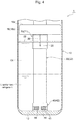
Fig. 4 is a partially cutaway side view ofFig. 3 . -
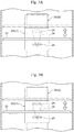
Fig. 5A is an enlarged side view of a main part of another embodiment of the accumulator in accordance with the present invention. -
Fig. 5B is an enlarged side view of a main part of another embodiment of the accumulator in accordance with the present invention. -
Fig. 6A is an enlarged vertical cross-sectional view of a main part of another embodiment of the accumulator in accordance with the present invention. -
Fig. 6B is an enlarged vertical cross-sectional view of a main part of another embodiment of the accumulator in accordance with the present invention. - Hereinafter, embodiments of the present invention will be described with reference to the drawings.
-
Fig. 1 andFig. 3 are vertical cross-sectional views each illustrating one embodiment of an accumulator in accordance with the present invention (Fig. 1 illustrates the accumulator during cooling operation andFig. 3 illustrates the accumulator during heating operation).Fig. 2 andFig. 4 are partially cutaway side views ofFig. 1 andFig. 3 , respectively. - An
accumulator 1 of the embodiment illustrated in the drawings is used as an accumulator in the heat pump systems of car air conditioners for electric vehicles, for example, and includes a closed-bottomedcylindrical tank 10 made of metal, such as stainless steel or aluminum alloy, and having an open upper face that is hermetically closed by acap member 12 made of the same metal. It should be noted that theaccumulator 1 of this embodiment is placed in a vertical, upright position as illustrated, for example. That is, thecap member 12 is located on the upper (top) side, and a bottom 13 of thetank 10 is located on the lower (bottom) side. - The
cap member 12 has aninlet port 15 and a steppedoutlet port 16 that are arranged side by side (specifically, in the right and left positions that are displaced from the center of the cap member 12). A gas-liquid separator 18 in the shape of a conical hat or an inverted wide bowl that has a slightly smaller diameter than the inside diameter of thetank 10 is arranged below thecap member 12. The upper end of anoutlet pipe 30 is coupled to the lower portion of theoutlet port 16. - The
outlet pipe 30 is coupled at its upper end to the lower portion of theoutlet port 16 through press-fitting, pipe expansion, swaging, and the like and has a double-pipe structure of aninner pipe 31, which is made of metal, for example, and extends downward within thetank 10 through a through-hole 19 provided in aceiling portion 18a of the gas-liquid separator 18, and a closed-bottomedouter pipe 32, which is made of synthetic resin, for example, and is arranged approximately coaxially with theinner pipe 31 on the outer periphery of theinner pipe 31. - Though not illustrated in the drawings, ribs for securing predetermined intervals therebetween may be formed on at least one of the
inner pipe 31 or theouter pipe 32. For example, a plurality of plate-like ribs is provided in an inwardly protruding manner in the radial direction on the inner periphery of theouter pipe 32 along the longitudinal direction (i.e., the vertical direction) and at equiangular intervals. Theinner pipe 31 is securely inserted on the inner periphery side of the plurality of plate-like ribs by press-fitting. - The plate-like ribs may be provided on the inner pipe 31 (or the lower portion thereof with respect to the gas-liquid separator 18) or may be provided on both of the
inner pipe 31 and theouter pipe 32. In addition, theinner pipe 31, theouter pipe 32, and the plate-like ribs may be integrally formed by extrusion using synthetic resin material, aluminum material, or the like. That is, the above-described double-pipe structure may be an integrally molded component made of aluminum extruded material, for example. - The lower end of the
outer pipe 32 is securely fitted into anupper portion 42a with a stepped inner periphery of acase 42 of a strainer 40 (described below) through press-fitting or the like. The lower end of theinner pipe 31 is located slightly above a bottom 32b of theouter pipe 32. The upper end of theouter pipe 32 is located slightly below thecap member 12. A lower oil return hole 35 (hereinafter simply referred to as the oil return hole 35) is formed in the center of the bottom 32b of theouter pipe 32. The diameter of theoil return hole 35 is set to about 1 mm, for example. - The gas-
liquid separator 18 is made of metal, such as stainless steel or aluminum alloy, and is securely arranged below theinlet port 15 so as to cover the opening (i.e., the opening at the other end of the outlet pipe 30) formed of theinner pipe 31 and the outer pipe 32 (or the upper end thereof) of theoutlet pipe 30. The gas-liquid separator 18 includes the disk-shapedceiling portion 18a, which is provided with the through-hole 19 having the upper end of the outlet pipe 30 (or theinner pipe 31 thereof) inserted thereinto and is disposed to face theinlet port 15, and a cylindricalperipheral wall 18b, which extends downward from the outer periphery of theceiling portion 18a. - To attach the gas-
liquid separator 18 to thecap member 12, the upper end of theinner pipe 31 securely inserted into the outer pipe 32 (or the plate-like ribs thereof) in advance is passed through the through-hole 19 provided in the gas-liquid separator 18 and is then fixed to theoutlet port 16 from the lower side through press-fitting, pipe expansion, swaging, and the like. Accordingly, the gas-liquid separator 18 is securely retained so as to be sandwiched between the plate-like ribs of theouter pipe 32 and the lower end face of thecap member 12. It should be noted that the gas-liquid separator 18 may be securely retained so as to be sandwiched between a flanged portion, which has been provided near the upper end of theinner pipe 31 through compression bending, such as bulge forming, and the lower end face of thecap member 12. - It should be noted that it is needless to mention that the method for arranging and attaching the outlet pipe 30 (or the
inner pipe 31 and theouter pipe 32 thereof) and the gas-liquid separator 18 may not be limited to the one described above. - The
strainer 40 is fixedly disposed on the bottom 13 of thetank 10 and includes a closed-bottomedcylindrical case 42 made of synthetic resin and acylindrical mesh filter 45 integrally formed with thecase 42 through insert molding. Themesh filter 45 is made of a metallic mesh or a mesh member of synthetic resin, for example. - The
case 42 of thestrainer 40 includes theupper portion 42a with a stepped inner periphery into which the lower end of theouter pipe 32 is securely fitted, abase plate 42c, and fourcolumnar portions 42b disposed upright on the outer periphery of thebase plate 42c at equiangular intervals to couple theupper portion 42a. Fourwindows 44 that are rectangular as seen in side view are defined between the four respectivecolumnar portions 42b, and themesh filter 45 is stretched over therespective windows 44. It should be noted that the method for providing themesh filter 45 in thecase 42 is not limited to the one described above. - In the
accumulator 1 with such a configuration, a low-temperature, low-pressure refrigerant in a gas-liquid mixed state from an evaporator is introduced into thetank 10 via theinlet port 15, as in the conventional one. The introduced refrigerant collides with the gas-liquid separator 18 (or theceiling portion 18a thereof) and is radially diffused to be separated into a liquid-phase refrigerant and a gas-phase refrigerant, and the liquid-phase refrigerant (including oil) flows downward along the inner peripheral face of thetank 10 and accumulates in the lower portion of thetank 10, while the gas-phase refrigerant is suctioned to the suction side of the compressor via the space (i.e., downward-feed flow channel 33) formed between theinner pipe 31 and theouter pipe 32 of theoutlet pipe 30 → the space inside of theinner pipe 31 so as to be circulated. - Oil that has accumulated in the lower portion of the
tank 10 together with the liquid-phase refrigerant moves toward the bottom 13 of thetank 10 due to the difference in specific gravity, properties, and the like between the oil and the liquid-phase refrigerant. The oil at the bottom 13 of thetank 10 is absorbed into the gas-phase refrigerant to be suctioned to the suction side of the compressor via theoutlet pipe 30 and then passes through themesh filter 45 of thestrainer 40 → theoil return hole 35 → the space inside of theinner pipe 31 and thus is returned to the suction side of the compressor together with the gas-phase refrigerant so as to be circulated. When the oil passes through themesh filter 45, foreign matter, such as sludge and the like, is trapped and thus is removed from the circulating refrigerant (including oil). - Here, in the heat pump system including the
accumulator 1 with such a configuration, during cooling operation (i.e., when the required load is high), a large amount of refrigerant is required for circulation, and thus the liquid-phase refrigerant (including oil) accumulated in thetank 10 of theaccumulator 1 decreases and its surface level becomes low (seeFig. 1 ,Fig. 2 ). Meanwhile, during heating operation (i.e., when the required load is low), a small amount of refrigerant circulates, and thus the liquid-phase refrigerant (including oil) accumulated in thetank 10 of theaccumulator 1 increases and its surface level becomes high (seeFig. 3 ,Fig. 4 ). - Furthermore, while the operation of the system (i.e., compressor) is stopping, the liquid portion including the liquid-phase refrigerant and oil accumulates in the lower portion of the
tank 10 of theaccumulator 1, and when the system uses oil that is not compatible with the refrigerant and has a lower specific gravity than the refrigerant, two separate layers, that is, an oil layer on the upper side and a liquid-phase refrigerant layer on the lower side, are formed due to the difference in specific gravity and viscosity between the liquid-phase refrigerant and the oil. - Therefore, when the system uses oil that is not compatible with the refrigerant and has a lower specific gravity than the refrigerant, during low-load operation, such as heating operation, for example, the oil layer is formed in the upper position inside of the
tank 10 of theaccumulator 1. This may reduce the oil return amount through theoil return hole 35. - The
accumulator 1 of the present embodiment takes the following measures to secure the oil return amount even in the above-described situations. - That is, in addition to the above configuration, in the present embodiment, a
slit hole 39 extending in the vertical direction is formed in the upper portion of theouter pipe 32 of theoutlet pipe 30 that is provided within thetank 10. In this example, thelong slit hole 39 with a length of about 1/6 of theouter pipe 32 and a constant width in the vertical direction is formed in the center side portion (near the center) of theouter pipe 32 eccentrically disposed in thetank 10, below the gas-liquid separator 18. The width (i.e., the width in the circumferential direction) of theslit hole 39 is set to about 1 mm, for example. - In addition, an approximately cylindrical floating
member 20 is disposed on (i.e., mounted around) the outer periphery of theouter pipe 32 so as to be slidable in the vertical direction. This floatingmember 20 is made of a material having a lower specific gravity than the oil, such as polypropylene (PP), a foamed material (including foam therein), or a porous material, for example, and a portion of the floatingmember 20 is immersed in the liquid portion (in particular, the oil layer) accumulated in thetank 10. The floatingmember 20 is adapted to move (i.e., float) up or down along the outer periphery of theouter pipe 32 with the buoyancy received from the liquid portion (in particular, the oil layer). - Specifically, the floating
member 20 includes a cylindrical slidingportion 21, which has a slightly larger vertical length than that of theslit hole 39 and is externally arranged around theoutlet pipe 31 so as to be slidable in the vertical direction, and a disk-like flange portion 22 extending (outwardly) from around the center of the sliding portion 21 (or the outer face thereof) to around the inner peripheral face (or the inner wall face) of thetank 10. In this example, theflange portion 22 has a slightly smaller outside diameter than the inside diameter of thetank 10, and a gap is formed between the flange portion 22 (or the outer end thereof) and the inner peripheral face of thetank 10 so as to allow the liquid-phase refrigerant (including oil) to flow downward to the lower portion of thetank 10. - In addition, an upper oil return hole 25 (hereinafter simply referred to as the oil return hole 25) made of a through-hole is formed in the lower portion of the sliding portion 21 (i.e., the lower portion with respect to the flange portion 22). In this example, the round
oil return hole 25 having a diameter approximately equal to the width (i.e., the width in the circumferential direction) of theslit hole 39 is formed in the slidingportion 21 on its center side portion (near the center) (that is, in the position in the same circumferential direction as the slit hole 39). The diameter of theoil return hole 25 is set to about 1 mm, for example. - In this example, due to the specific gravity of the oil and the floating
member 20, the shape and volume of the floatingmember 20, and the like, the floatingmember 20 is adapted to float with the buoyancy received from the liquid portion when the lower portion of the slidingportion 21 with respect to the flange portion 22 (i.e., the portion including the oil return hole 25) or the lower portion of the slidingportion 21 with respect to theflange portion 22 as well as a portion of theflange portion 22 is/are immersed in the liquid portion accumulated in thetank 10. In other words, in this case, theflange portion 22 is adapted to float on the liquid portion (specifically, the oil layer on the upper side). - Accordingly, with the buoyancy received from the liquid portion (in particular, the oil layer) accumulated in the
tank 10 of theaccumulator 1, the floatingmember 20 is adapted to move up or down along the outer periphery of the outer pipe 32 (that is, move while sliding on the outer periphery of the outer pipe 32) according to the surface level of the liquid portion, specifically, the oil surface level of the oil layer on the upper side. - It should be noted that in the illustrated example, the approximately lower half of the floating
member 20 is immersed only in the oil layer of the liquid portion accumulated in thetank 10, and the floatingmember 20 is adapted to move up or down with the buoyancy received only from the oil layer of the liquid portion. However, it is needless to mention that as long as theoil return hole 25 is provided at least in the portion to be immersed in the oil, a portion of the floatingmember 20 may be immersed in the liquid-phase refrigerant layer on the lower side of the liquid portion, and the floatingmember 20 may be adapted to move up or down with the buoyancy received from both of the oil layer and the liquid-phase refrigerant layer of the liquid portion, for example. - Therefore, in the
accumulator 1 with such a configuration, during high-load operation, such as cooling operation as illustrated inFig. 1 andFig. 2 for example, when the surface level of the liquid portion accumulated in the tank 10 (specifically, the oil surface level of the oil layer on the upper side) is lower than or equal to a predetermined level, theoil return hole 25 formed in the lower portion of the floating member 20 (or the slidingportion 21 thereof) is located below theslit hole 39 formed in the upper portion of theouter pipe 32, and theoil return hole 25 is closed (blocked) by the outer periphery (i.e., the outer peripheral face) of theouter pipe 32. - Meanwhile, during low-load operation, such as heating operation as illustrated in
Fig. 3 andFig. 4 for example, when the oil surface level of the liquid portion accumulated in the tank 10 (specifically, the oil surface level of the oil layer on the upper side) exceeds the predetermined level, theoil return hole 25 formed in the lower portion of the floating member 20 (or the slidingportion 21 thereof) is adapted to communicate with theslit hole 39 formed in the upper portion of theouter pipe 32. Accordingly, when the system (i.e., compressor) is activated in such a state, the oil accumulated in thetank 10 is absorbed into the gas-phase refrigerant to be suctioned to the suction side of the compressor via theoutlet pipe 30 and then passes through theoil return hole 25 of the floatingmember 20 → theslit hole 39 of theouter pipe 32 → the space (i.e., downward-feed flow channel 33) formed between theinner pipe 31 and theouter pipe 32 of theoutlet pipe 30 → the space inside of theinner pipe 31 and thus is returned to the suction side of the compressor together with the gas-phase refrigerant so as to be circulated. - As described above, in the
accumulator 1 of the present embodiment, when the surface level of the oil accumulated in the tank 10 (i.e., oil surface level) exceeds the predetermined level, theoil return hole 25 provided in the floating member 20 (or the slidingportion 21 thereof) is adapted to be continuous (communicate) with theslit hole 39 provided in the outlet pipe 30 (or theouter pipe 32 thereof), and the oil is returned to theoutlet pipe 30 through theoil return hole 25 and theslit hole 39, consequently to the suction side of the compressor. This can increase the oil return amount even when thetank 10 of theaccumulator 1 has a large liquid portion accumulated therein and the liquid portion is in a two-layer separate state (i.e., the oil layer on the upper side and the liquid-phase refrigerant layer on the lower side) with use of the oil that is not compatible with the refrigerant and has a lower specific gravity than the refrigerant, thus forming the oil layer in the upper position inside of thetank 10 of theaccumulator 1, for example. As a result, the system can improve the operation efficiency (for example, heating efficiency). - In this case, basically the floating
member 20 made of a material having a lower specific gravity than the oil, a foamed material, a porous material, for example, may be disposed on the outer periphery of the outlet pipe 30 (or theouter pipe 32 thereof). This can simplify the configuration of theaccumulator 1, reduce the number of components, achieve cost reduction, for example, as compared to the conventional one using moving means or the like. - In addition, the floating
member 20 includes the cylindrical slidingportion 21 externally arranged around the outlet pipe 31 (or theouter pipe 32 thereof) so as to be slidable, and the disk-like flange portion 22 extending outwardly from the slidingportion 21. The slidingportion 21 is provided with theoil return hole 25 on the lower side with respect to theflange portion 22, and theflange portion 22 serves as a cap adapted to cover the top of the liquid portion accumulated in thetank 10 of theaccumulator 1, that is, the top of the oil layer on the upper side in the two-layer separate state, for example. This can prevent the turbulence of the liquid portion accumulated in thetank 10 of theaccumulator 1 and also increase the gas-liquid separation performance. - It should be noted that it is needless to mention that the position, size, and shape of the
slit hole 39 of the outlet pipe 30 (or theouter pipe 32 thereof) and the number of slit holes 39, the shape of the floatingmember 20, the position, size, and shape of theoil return hole 25 of the floatingmember 20 and the number of oil return holes 25, or the like may not be limited to those of the above-described example. - For example, in the above embodiment, although the floating
member 20 has an approximately cylindrical shape surrounding the entire outer periphery (i.e., perimeter) of the outlet pipe 30 (or theouter pipe 32 thereof), the floatingmember 20 may have a shape that surrounds only a portion of the outer periphery of the outlet pipe 30 (or theouter pipe 32 thereof) (specifically, at least a portion including the slit hole 39). - In addition, as illustrated in
Fig. 5A and Fig. 5B for example, the width (i.e., the width in the circumferential direction) of theslit hole 39 of the outlet pipe 30 (or theouter pipe 32 thereof) may be varied in the vertical direction and the width (i.e., the width in the circumferential direction) of theoil return hole 25 of the floatingmember 20 may be set larger than the width of the narrowest portion of theslit hole 39. In the example illustrated inFig. 5A , the width of theslit hole 39 increases continuously from its bottom to top (in other words, theslit hole 39 is formed to be tapered), and the width of theoil return hole 25 is set larger than the width of the lower end portion of theslit hole 39. Further, in the example illustrated inFig. 5B , the width of theslit hole 39 increases in stages from its bottom to top (in other words, theslit hole 39 is formed into steps), and the width of theoil return hole 25 is set larger than the width of the lower end portion of theslit hole 39. - With the configurations illustrated in
Fig. 5A and Fig. 5B , the area of the portion in which theslit hole 39 and theoil return hole 25 overlap each other changes depending on the position (that is, the surface level of the liquid portion, specifically, the oil surface level of the oil layer on the upper side) of the floatingmember 20 with respect to the outlet pipe 30 (or theouter pipe 32 thereof). This can change the oil return amount. In the examples illustrated inFig. 5A and Fig. 5B , the oil return amount is adapted to increase as the surface level of the liquid portion, specifically the oil surface level of the oil layer on the upper side, increases. - In addition, although one
slit hole 39 and oneoil return hole 25 are provided in the above embodiment, a plurality of slit holes 39 and a plurality of oil return holes 25 may be formed in the circumferential direction of theouter pipe 32 and the floatingmember 20, respectively. In this case, as illustrated inFig. 6A and Fig. 6B for example, the slit holes 39 or oil return holes 25 formed in different positions (in the circumferential direction) may be in various vertical positions (including upper and lower end positions, central positions, vertical lengths). In the example illustrated inFig. 6A , the plurality of slit holes 39 is formed in different positions in the circumferential direction of theouter pipe 32, and the slit holes 39 are set to be in different vertical positions (i.e., different lower end positions in the illustrated example) in the vertical direction. Meanwhile, in the example illustrated inFig. 6B , the plurality of oil return holes 25 is formed in different positions in the circumferential direction of the floating member 20 (or the slidingportion 21 thereof), and the oil return holes 25 are set to be in different vertical positions (i.e., different central positions) in the vertical direction. - With the configurations illustrated in
Fig. 6A and Fig. 6B , as in the examples illustrated inFig. 5A and Fig. 5B , the area (i.e., the total area) of the portion in which the slit holes 39 and the oil return holes 25 overlap each other changes depending on the position (that is, the surface level of the liquid portion, specifically, the oil surface level of the oil layer on the upper side) of the floatingmember 20 with respect to the outlet pipe 30 (or theouter pipe 32 thereof). This can change the oil return amount. In the examples illustrated inFig. 6A and Fig. 6B , the oil return amount is adapted to increase as the surface level of the liquid portion, specifically the oil surface level of the oil layer on the upper side, increases. - When the plurality of slit holes 39 or the plurality of oil return holes 25 is formed, it is needless to mention that the slit holes 39 or the oil return holes 25 do not need to be located in the same position (height), or to have the same size (width in the circumferential direction, diameter, or the like), shape, or the like.
- In addition, in the above embodiment, since the
outlet pipe 30 provided within thetank 10 is eccentrically disposed in thetank 10, the floatingmember 20 is substantially prevented from rotating around theoutlet pipe 30. However, in order to surely prevent the floatingmember 20 from rotating around theoutlet pipe 30, a guide mechanism for guiding the floatingmember 20 so as to be vertically movable with respect to the outlet pipe 30 (or theouter pipe 32 thereof) may be provided between the outlet pipe 30 (or theouter pipe 32 thereof) and the floating member 20 (or the slidingportion 21 thereof). For example, a protrusion or a projection extending in the vertical direction, for example, may be formed on one of the outer periphery of the outlet pipe 30 (or theouter pipe 32 thereof) or the inner periphery of the floating member 20 (or the slidingportion 21 thereof) and, for example, a recessed groove extending in the vertical direction, into which the protrusion or the projection extending in the vertical direction, for example, is fitted, may be formed on the other one of the outer periphery of the outlet pipe 30 (or theouter pipe 32 thereof) or the inner periphery of the floating member 20 (or the slidingportion 21 thereof). - Although the above embodiment adopts the
outlet pipe 30 having a double-pipe structure of theinner pipe 31 and theouter pipe 32, it is needless to mention that the present invention can also be applied to an accumulator with an outlet pipe of, for example, a U-shaped pipe (i.e., a pipe formed into a U-shape) or a straight pipe (i.e., a pipe formed into a straight line) that is coupled at one end to the outlet port and is open at the other end near the lower face of a gas-liquid separator. - In addition, the above embodiment shows the example in which the oil and the liquid-phase refrigerant are in a two-layer separate state (i.e., the oil layer on the upper side and the liquid-phase refrigerant layer on the lower side) as described above while the operation of the compressor is stopping with use of the oil that is not compatible with the refrigerant and has a lower specific gravity than the refrigerant. However, it is needless to explain in detail that by designing the floating
member 20 according to the type, properties, or the like of the refrigerant and oil, the present invention can also be applied even when the oil and the liquid-phase refrigerant are not in a two-layer separate state as described above while the operation of the compressor is stopping, that is, even when a liquid-phase refrigerant layer on the upper side and an oil layer on the lower side are formed while the operation of the compressor is stopping with use of the oil that is not compatible with the refrigerant and has a higher specific gravity than the refrigerant. -
- 1
- Accumulator
- 10
- Tank
- 12
- Cap member
- 13
- Bottom of tank
- 15
- Inlet port
- 16
- Outlet port
- 18
- Gas-liquid separator
- 18a
- Ceiling portion
- 18b
- Peripheral wall
- 19
- Through-hole
- 20
- Floating member
- 21
- Sliding portion
- 22
- Flange portion
- 25
- Upper oil return hole
- 30
- Outlet pipe
- 31
- Inner pipe
- 32
- Outer pipe
- 32b
- Bottom of outer pipe
- 33
- Downward-feed flow channel
- 35
- Lower oil return hole
- 39
- Slit hole
- 40
- Strainer
- 42
- Case
- 44
- Window
- 45
- Mesh filter
Claims (13)
- An accumulator comprising:a tank having an inlet port and an outlet port;an outlet pipe provided within the tank, the outlet pipe being coupled at one end to the outlet port and being open at another end inside of the tank; anda gas-liquid separator adapted to separate a refrigerant introduced into the tank via the inlet port into a liquid-phase refrigerant and a gas-phase refrigerant,wherein:a floating member is disposed on an outer periphery of the outlet pipe so as to be slidable in a vertical direction, the floating member being adapted to move up or down according to change in an oil surface level with buoyancy received from oil included in the refrigerant, and being provided with an oil return hole in a portion to be immersed in the oil, andthe outlet pipe is provided with a slit hole extending in the vertical direction and being adapted to be continuous with the oil return hole when the oil surface level exceeds a predetermined level.
- The accumulator according to claim 1, wherein:when the oil surface level is lower than or equal to the predetermined level, the oil return hole is located below the slit hole such that the oil return hole is closed by the outlet pipe, andwhen the oil surface level exceeds the predetermined level, the oil return hole is adapted to communicate with the slit hole such that the oil accumulated in the tank is returned to the outlet pipe through the oil return hole and the slit hole.
- The accumulator according to claim 1 or 2, wherein the outlet pipe has a double-pipe structure of an inner pipe and an outer pipe.
- The accumulator according to any one of claims 1 to 3, wherein the tank has a cylindrical shape, and the outlet pipe is eccentrically disposed in the tank.
- The accumulator according to any one of claims 1 to 4, wherein:the floating member includes a cylindrical sliding portion externally arranged around the outlet pipe so as to be slidable and a plate-like flange portion extending outwardly from the sliding portion, andthe oil return hole is provided in a lower portion of the sliding portion with respect to the flange portion.
- The accumulator according to claim 5, wherein the flange portion is adapted to float on the oil accumulated in the tank.
- The accumulator according to claim 5 or 6, wherein the sliding portion has a larger vertical length than a vertical length of the slit hole.
- The accumulator according to any one of claims 1 to 7, wherein the floating member is made of a material having a lower specific gravity than the oil, a foamed material, or a porous material.
- The accumulator according to any one of claims 1 to 8, wherein:the slit hole has a width in a circumferential direction that is varied in a vertical direction, andthe oil return hole has a width in a circumferential direction that is larger than at least a width in a circumferential direction of a narrowest portion of the slit hole.
- The accumulator according to claim 9, wherein the slit hole has a width in a circumferential direction that is varied continuously or in stages in a vertical direction.
- The accumulator according to any one of claims 1 to 10, wherein the slit hole includes a plurality of slit holes provided in different positions in a circumferential direction of the outlet pipe and in different vertical positions in a vertical direction.
- The accumulator according to any one of claims 1 to 11, wherein the oil return hole includes a plurality of oil return holes provided in different positions in a circumferential direction of the floating member and in different vertical positions in a vertical direction.
- The accumulator according to any one of claims 1 to 12, wherein a guide mechanism for guiding the floating member so as to be vertically movable with respect to the outlet pipe is provided between the outlet pipe and the floating member.
Applications Claiming Priority (2)
| Application Number | Priority Date | Filing Date | Title |
|---|---|---|---|
| JP2019029005A JP7054222B2 (en) | 2019-02-21 | 2019-02-21 | accumulator |
| PCT/JP2020/000283 WO2020170627A1 (en) | 2019-02-21 | 2020-01-08 | Accumulator |
Publications (3)
| Publication Number | Publication Date |
|---|---|
| EP3929505A1 true EP3929505A1 (en) | 2021-12-29 |
| EP3929505A4 EP3929505A4 (en) | 2022-10-26 |
| EP3929505B1 EP3929505B1 (en) | 2023-11-22 |
Family
ID=72144575
Family Applications (1)
| Application Number | Title | Priority Date | Filing Date |
|---|---|---|---|
| EP20759184.3A Active EP3929505B1 (en) | 2019-02-21 | 2020-01-08 | Accumulator |
Country Status (4)
| Country | Link |
|---|---|
| EP (1) | EP3929505B1 (en) |
| JP (1) | JP7054222B2 (en) |
| CN (1) | CN113439189B (en) |
| WO (1) | WO2020170627A1 (en) |
Families Citing this family (4)
| Publication number | Priority date | Publication date | Assignee | Title |
|---|---|---|---|---|
| CN112611135A (en) * | 2020-12-04 | 2021-04-06 | 青岛海信日立空调系统有限公司 | Gas-liquid separator and heat pump system |
| CN114812000B (en) * | 2022-05-24 | 2023-04-28 | 珠海格力电器股份有限公司 | Oil return device of dual-mode fluorine pump refrigerating system, control method of oil return device and machine room air conditioner |
| CN115977958B (en) * | 2023-01-04 | 2026-04-10 | 珠海格力节能环保制冷技术研究中心有限公司 | An oil return assembly and a compressor |
| CN117213082A (en) * | 2023-10-20 | 2023-12-12 | 中国船舶集团有限公司第七一九研究所 | Marine anti-turbulence refrigeration system and control method |
Family Cites Families (13)
| Publication number | Priority date | Publication date | Assignee | Title |
|---|---|---|---|---|
| JPS5714166A (en) * | 1980-07-01 | 1982-01-25 | Nihon Radiator Co | Airconditioner for automobile |
| JPH02272272A (en) * | 1989-04-13 | 1990-11-07 | Matsushita Refrig Co Ltd | Accumulator for freezer |
| JP3104513B2 (en) * | 1993-12-28 | 2000-10-30 | 三菱電機株式会社 | accumulator |
| JPH094934A (en) * | 1995-06-20 | 1997-01-10 | Sanyo Electric Co Ltd | Deep freezer |
| JP3339302B2 (en) * | 1996-04-26 | 2002-10-28 | 三菱電機株式会社 | accumulator |
| JPH10205931A (en) * | 1997-01-22 | 1998-08-04 | Matsushita Refrig Co Ltd | Accumulator |
| KR100669289B1 (en) * | 2004-12-09 | 2007-01-15 | 주식회사 대우일렉트로닉스 | Capacity variable accumulator |
| CN101109590B (en) * | 2006-07-17 | 2011-07-20 | 上海日立电器有限公司 | Floater type liquid container |
| KR20100085258A (en) * | 2009-01-20 | 2010-07-29 | 주식회사 대우일렉트로닉스 | Accumulator for refrigerator |
| JP2011064409A (en) * | 2009-09-17 | 2011-03-31 | Sanden Corp | Liquid receiver and refrigerating circuit including the same |
| JP6068909B2 (en) | 2012-10-02 | 2017-01-25 | 株式会社不二工機 | accumulator |
| JP6762025B2 (en) * | 2016-08-17 | 2020-09-30 | 株式会社不二工機 | accumulator |
| CN209558732U (en) * | 2019-01-08 | 2019-10-29 | 湖南汤普悦斯压缩机科技有限公司 | A kind of gas-liquid separator |
-
2019
- 2019-02-21 JP JP2019029005A patent/JP7054222B2/en active Active
-
2020
- 2020-01-08 CN CN202080014747.6A patent/CN113439189B/en active Active
- 2020-01-08 EP EP20759184.3A patent/EP3929505B1/en active Active
- 2020-01-08 WO PCT/JP2020/000283 patent/WO2020170627A1/en not_active Ceased
Also Published As
| Publication number | Publication date |
|---|---|
| JP2020134039A (en) | 2020-08-31 |
| CN113439189B (en) | 2023-01-10 |
| WO2020170627A1 (en) | 2020-08-27 |
| JP7054222B2 (en) | 2022-04-13 |
| EP3929505A4 (en) | 2022-10-26 |
| EP3929505B1 (en) | 2023-11-22 |
| CN113439189A (en) | 2021-09-24 |
Similar Documents
| Publication | Publication Date | Title |
|---|---|---|
| EP3929505A1 (en) | Accumulator | |
| US10190809B2 (en) | Accumulator | |
| US10926608B2 (en) | Refrigerant container | |
| EP2469202A2 (en) | Accumulator for refrigeration cycle system | |
| US10989457B2 (en) | Accumulator | |
| JP2017026192A (en) | accumulator | |
| CN106352620B (en) | Liquid storage device | |
| EP3677857A1 (en) | Accumulator | |
| EP3118543B1 (en) | Accumulator | |
| US10821811B2 (en) | Refrigerant container | |
| KR102180361B1 (en) | Device for storing refrigerant of a refrigerant circuit system, and method for operating the device | |
| EP3671074B1 (en) | Accumulator | |
| JP2017015366A (en) | accumulator | |
| JP2015064128A (en) | Accumulator and refrigeration equipment | |
| EP4379291A1 (en) | Refrigerant storage container, and refrigeration cycle device provided with said refrigerant storage container | |
| JP5982114B2 (en) | Gas-liquid separator | |
| KR100600625B1 (en) | Oil separator | |
| KR20000032417A (en) | Oil separator | |
| WO2018079182A1 (en) | Accumulator |
Legal Events
| Date | Code | Title | Description |
|---|---|---|---|
| STAA | Information on the status of an ep patent application or granted ep patent |
Free format text: STATUS: THE INTERNATIONAL PUBLICATION HAS BEEN MADE |
|
| PUAI | Public reference made under article 153(3) epc to a published international application that has entered the european phase |
Free format text: ORIGINAL CODE: 0009012 |
|
| STAA | Information on the status of an ep patent application or granted ep patent |
Free format text: STATUS: REQUEST FOR EXAMINATION WAS MADE |
|
| 17P | Request for examination filed |
Effective date: 20210920 |
|
| AK | Designated contracting states |
Kind code of ref document: A1 Designated state(s): AL AT BE BG CH CY CZ DE DK EE ES FI FR GB GR HR HU IE IS IT LI LT LU LV MC MK MT NL NO PL PT RO RS SE SI SK SM TR |
|
| DAV | Request for validation of the european patent (deleted) | ||
| DAX | Request for extension of the european patent (deleted) | ||
| A4 | Supplementary search report drawn up and despatched |
Effective date: 20220928 |
|
| RIC1 | Information provided on ipc code assigned before grant |
Ipc: F25B 43/02 20060101ALI20220922BHEP Ipc: F25B 43/00 20060101AFI20220922BHEP |
|
| STAA | Information on the status of an ep patent application or granted ep patent |
Free format text: STATUS: EXAMINATION IS IN PROGRESS |
|
| 17Q | First examination report despatched |
Effective date: 20230330 |
|
| GRAP | Despatch of communication of intention to grant a patent |
Free format text: ORIGINAL CODE: EPIDOSNIGR1 |
|
| STAA | Information on the status of an ep patent application or granted ep patent |
Free format text: STATUS: GRANT OF PATENT IS INTENDED |
|
| INTG | Intention to grant announced |
Effective date: 20230616 |
|
| GRAS | Grant fee paid |
Free format text: ORIGINAL CODE: EPIDOSNIGR3 |
|
| GRAA | (expected) grant |
Free format text: ORIGINAL CODE: 0009210 |
|
| STAA | Information on the status of an ep patent application or granted ep patent |
Free format text: STATUS: THE PATENT HAS BEEN GRANTED |
|
| AK | Designated contracting states |
Kind code of ref document: B1 Designated state(s): AL AT BE BG CH CY CZ DE DK EE ES FI FR GB GR HR HU IE IS IT LI LT LU LV MC MK MT NL NO PL PT RO RS SE SI SK SM TR |
|
| REG | Reference to a national code |
Ref country code: GB Ref legal event code: FG4D |
|
| REG | Reference to a national code |
Ref country code: CH Ref legal event code: EP Ref country code: DE Ref legal event code: R096 Ref document number: 602020021548 Country of ref document: DE |
|
| REG | Reference to a national code |
Ref country code: IE Ref legal event code: FG4D |
|
| REG | Reference to a national code |
Ref country code: LT Ref legal event code: MG9D |
|
| REG | Reference to a national code |
Ref country code: NL Ref legal event code: MP Effective date: 20231122 |
|
| PG25 | Lapsed in a contracting state [announced via postgrant information from national office to epo] |
Ref country code: GR Free format text: LAPSE BECAUSE OF FAILURE TO SUBMIT A TRANSLATION OF THE DESCRIPTION OR TO PAY THE FEE WITHIN THE PRESCRIBED TIME-LIMIT Effective date: 20240223 |
|
| PG25 | Lapsed in a contracting state [announced via postgrant information from national office to epo] |
Ref country code: IS Free format text: LAPSE BECAUSE OF FAILURE TO SUBMIT A TRANSLATION OF THE DESCRIPTION OR TO PAY THE FEE WITHIN THE PRESCRIBED TIME-LIMIT Effective date: 20240322 |
|
| PG25 | Lapsed in a contracting state [announced via postgrant information from national office to epo] |
Ref country code: LT Free format text: LAPSE BECAUSE OF FAILURE TO SUBMIT A TRANSLATION OF THE DESCRIPTION OR TO PAY THE FEE WITHIN THE PRESCRIBED TIME-LIMIT Effective date: 20231122 |
|
| REG | Reference to a national code |
Ref country code: AT Ref legal event code: MK05 Ref document number: 1634188 Country of ref document: AT Kind code of ref document: T Effective date: 20231122 |
|
| PG25 | Lapsed in a contracting state [announced via postgrant information from national office to epo] |
Ref country code: NL Free format text: LAPSE BECAUSE OF FAILURE TO SUBMIT A TRANSLATION OF THE DESCRIPTION OR TO PAY THE FEE WITHIN THE PRESCRIBED TIME-LIMIT Effective date: 20231122 |
|
| PG25 | Lapsed in a contracting state [announced via postgrant information from national office to epo] |
Ref country code: AT Free format text: LAPSE BECAUSE OF FAILURE TO SUBMIT A TRANSLATION OF THE DESCRIPTION OR TO PAY THE FEE WITHIN THE PRESCRIBED TIME-LIMIT Effective date: 20231122 |
|
| PG25 | Lapsed in a contracting state [announced via postgrant information from national office to epo] |
Ref country code: ES Free format text: LAPSE BECAUSE OF FAILURE TO SUBMIT A TRANSLATION OF THE DESCRIPTION OR TO PAY THE FEE WITHIN THE PRESCRIBED TIME-LIMIT Effective date: 20231122 |
|
| PG25 | Lapsed in a contracting state [announced via postgrant information from national office to epo] |
Ref country code: NL Free format text: LAPSE BECAUSE OF FAILURE TO SUBMIT A TRANSLATION OF THE DESCRIPTION OR TO PAY THE FEE WITHIN THE PRESCRIBED TIME-LIMIT Effective date: 20231122 Ref country code: LT Free format text: LAPSE BECAUSE OF FAILURE TO SUBMIT A TRANSLATION OF THE DESCRIPTION OR TO PAY THE FEE WITHIN THE PRESCRIBED TIME-LIMIT Effective date: 20231122 Ref country code: IS Free format text: LAPSE BECAUSE OF FAILURE TO SUBMIT A TRANSLATION OF THE DESCRIPTION OR TO PAY THE FEE WITHIN THE PRESCRIBED TIME-LIMIT Effective date: 20240322 Ref country code: GR Free format text: LAPSE BECAUSE OF FAILURE TO SUBMIT A TRANSLATION OF THE DESCRIPTION OR TO PAY THE FEE WITHIN THE PRESCRIBED TIME-LIMIT Effective date: 20240223 Ref country code: ES Free format text: LAPSE BECAUSE OF FAILURE TO SUBMIT A TRANSLATION OF THE DESCRIPTION OR TO PAY THE FEE WITHIN THE PRESCRIBED TIME-LIMIT Effective date: 20231122 Ref country code: BG Free format text: LAPSE BECAUSE OF FAILURE TO SUBMIT A TRANSLATION OF THE DESCRIPTION OR TO PAY THE FEE WITHIN THE PRESCRIBED TIME-LIMIT Effective date: 20240222 Ref country code: AT Free format text: LAPSE BECAUSE OF FAILURE TO SUBMIT A TRANSLATION OF THE DESCRIPTION OR TO PAY THE FEE WITHIN THE PRESCRIBED TIME-LIMIT Effective date: 20231122 Ref country code: PT Free format text: LAPSE BECAUSE OF FAILURE TO SUBMIT A TRANSLATION OF THE DESCRIPTION OR TO PAY THE FEE WITHIN THE PRESCRIBED TIME-LIMIT Effective date: 20240322 |
|
| PG25 | Lapsed in a contracting state [announced via postgrant information from national office to epo] |
Ref country code: SE Free format text: LAPSE BECAUSE OF FAILURE TO SUBMIT A TRANSLATION OF THE DESCRIPTION OR TO PAY THE FEE WITHIN THE PRESCRIBED TIME-LIMIT Effective date: 20231122 Ref country code: RS Free format text: LAPSE BECAUSE OF FAILURE TO SUBMIT A TRANSLATION OF THE DESCRIPTION OR TO PAY THE FEE WITHIN THE PRESCRIBED TIME-LIMIT Effective date: 20231122 Ref country code: PL Free format text: LAPSE BECAUSE OF FAILURE TO SUBMIT A TRANSLATION OF THE DESCRIPTION OR TO PAY THE FEE WITHIN THE PRESCRIBED TIME-LIMIT Effective date: 20231122 Ref country code: NO Free format text: LAPSE BECAUSE OF FAILURE TO SUBMIT A TRANSLATION OF THE DESCRIPTION OR TO PAY THE FEE WITHIN THE PRESCRIBED TIME-LIMIT Effective date: 20240222 Ref country code: LV Free format text: LAPSE BECAUSE OF FAILURE TO SUBMIT A TRANSLATION OF THE DESCRIPTION OR TO PAY THE FEE WITHIN THE PRESCRIBED TIME-LIMIT Effective date: 20231122 Ref country code: HR Free format text: LAPSE BECAUSE OF FAILURE TO SUBMIT A TRANSLATION OF THE DESCRIPTION OR TO PAY THE FEE WITHIN THE PRESCRIBED TIME-LIMIT Effective date: 20231122 |
|
| PG25 | Lapsed in a contracting state [announced via postgrant information from national office to epo] |
Ref country code: DK Free format text: LAPSE BECAUSE OF FAILURE TO SUBMIT A TRANSLATION OF THE DESCRIPTION OR TO PAY THE FEE WITHIN THE PRESCRIBED TIME-LIMIT Effective date: 20231122 |
|
| PG25 | Lapsed in a contracting state [announced via postgrant information from national office to epo] |
Ref country code: CZ Free format text: LAPSE BECAUSE OF FAILURE TO SUBMIT A TRANSLATION OF THE DESCRIPTION OR TO PAY THE FEE WITHIN THE PRESCRIBED TIME-LIMIT Effective date: 20231122 |
|
| PG25 | Lapsed in a contracting state [announced via postgrant information from national office to epo] |
Ref country code: SK Free format text: LAPSE BECAUSE OF FAILURE TO SUBMIT A TRANSLATION OF THE DESCRIPTION OR TO PAY THE FEE WITHIN THE PRESCRIBED TIME-LIMIT Effective date: 20231122 |
|
| PG25 | Lapsed in a contracting state [announced via postgrant information from national office to epo] |
Ref country code: SM Free format text: LAPSE BECAUSE OF FAILURE TO SUBMIT A TRANSLATION OF THE DESCRIPTION OR TO PAY THE FEE WITHIN THE PRESCRIBED TIME-LIMIT Effective date: 20231122 Ref country code: SK Free format text: LAPSE BECAUSE OF FAILURE TO SUBMIT A TRANSLATION OF THE DESCRIPTION OR TO PAY THE FEE WITHIN THE PRESCRIBED TIME-LIMIT Effective date: 20231122 Ref country code: RO Free format text: LAPSE BECAUSE OF FAILURE TO SUBMIT A TRANSLATION OF THE DESCRIPTION OR TO PAY THE FEE WITHIN THE PRESCRIBED TIME-LIMIT Effective date: 20231122 Ref country code: EE Free format text: LAPSE BECAUSE OF FAILURE TO SUBMIT A TRANSLATION OF THE DESCRIPTION OR TO PAY THE FEE WITHIN THE PRESCRIBED TIME-LIMIT Effective date: 20231122 Ref country code: DK Free format text: LAPSE BECAUSE OF FAILURE TO SUBMIT A TRANSLATION OF THE DESCRIPTION OR TO PAY THE FEE WITHIN THE PRESCRIBED TIME-LIMIT Effective date: 20231122 Ref country code: CZ Free format text: LAPSE BECAUSE OF FAILURE TO SUBMIT A TRANSLATION OF THE DESCRIPTION OR TO PAY THE FEE WITHIN THE PRESCRIBED TIME-LIMIT Effective date: 20231122 |
|
| REG | Reference to a national code |
Ref country code: DE Ref legal event code: R097 Ref document number: 602020021548 Country of ref document: DE |
|
| PG25 | Lapsed in a contracting state [announced via postgrant information from national office to epo] |
Ref country code: MC Free format text: LAPSE BECAUSE OF FAILURE TO SUBMIT A TRANSLATION OF THE DESCRIPTION OR TO PAY THE FEE WITHIN THE PRESCRIBED TIME-LIMIT Effective date: 20231122 |
|
| PG25 | Lapsed in a contracting state [announced via postgrant information from national office to epo] |
Ref country code: MC Free format text: LAPSE BECAUSE OF FAILURE TO SUBMIT A TRANSLATION OF THE DESCRIPTION OR TO PAY THE FEE WITHIN THE PRESCRIBED TIME-LIMIT Effective date: 20231122 |
|
| REG | Reference to a national code |
Ref country code: CH Ref legal event code: PL |
|
| PG25 | Lapsed in a contracting state [announced via postgrant information from national office to epo] |
Ref country code: LU Free format text: LAPSE BECAUSE OF NON-PAYMENT OF DUE FEES Effective date: 20240108 |
|
| PLBE | No opposition filed within time limit |
Free format text: ORIGINAL CODE: 0009261 |
|
| STAA | Information on the status of an ep patent application or granted ep patent |
Free format text: STATUS: NO OPPOSITION FILED WITHIN TIME LIMIT |
|
| PG25 | Lapsed in a contracting state [announced via postgrant information from national office to epo] |
Ref country code: LU Free format text: LAPSE BECAUSE OF NON-PAYMENT OF DUE FEES Effective date: 20240108 |
|
| PG25 | Lapsed in a contracting state [announced via postgrant information from national office to epo] |
Ref country code: BE Free format text: LAPSE BECAUSE OF NON-PAYMENT OF DUE FEES Effective date: 20240131 |
|
| PG25 | Lapsed in a contracting state [announced via postgrant information from national office to epo] |
Ref country code: CH Free format text: LAPSE BECAUSE OF NON-PAYMENT OF DUE FEES Effective date: 20240131 |
|
| GBPC | Gb: european patent ceased through non-payment of renewal fee |
Effective date: 20240222 |
|
| PG25 | Lapsed in a contracting state [announced via postgrant information from national office to epo] |
Ref country code: SI Free format text: LAPSE BECAUSE OF FAILURE TO SUBMIT A TRANSLATION OF THE DESCRIPTION OR TO PAY THE FEE WITHIN THE PRESCRIBED TIME-LIMIT Effective date: 20231122 |
|
| 26N | No opposition filed |
Effective date: 20240823 |
|
| PG25 | Lapsed in a contracting state [announced via postgrant information from national office to epo] |
Ref country code: SI Free format text: LAPSE BECAUSE OF FAILURE TO SUBMIT A TRANSLATION OF THE DESCRIPTION OR TO PAY THE FEE WITHIN THE PRESCRIBED TIME-LIMIT Effective date: 20231122 Ref country code: CH Free format text: LAPSE BECAUSE OF NON-PAYMENT OF DUE FEES Effective date: 20240131 Ref country code: BE Free format text: LAPSE BECAUSE OF NON-PAYMENT OF DUE FEES Effective date: 20240131 |
|
| REG | Reference to a national code |
Ref country code: BE Ref legal event code: MM Effective date: 20240131 |
|
| PG25 | Lapsed in a contracting state [announced via postgrant information from national office to epo] |
Ref country code: GB Free format text: LAPSE BECAUSE OF NON-PAYMENT OF DUE FEES Effective date: 20240222 |
|
| PG25 | Lapsed in a contracting state [announced via postgrant information from national office to epo] |
Ref country code: IE Free format text: LAPSE BECAUSE OF NON-PAYMENT OF DUE FEES Effective date: 20240108 |
|
| PG25 | Lapsed in a contracting state [announced via postgrant information from national office to epo] |
Ref country code: IE Free format text: LAPSE BECAUSE OF NON-PAYMENT OF DUE FEES Effective date: 20240108 Ref country code: GB Free format text: LAPSE BECAUSE OF NON-PAYMENT OF DUE FEES Effective date: 20240222 |
|
| PG25 | Lapsed in a contracting state [announced via postgrant information from national office to epo] |
Ref country code: CY Free format text: LAPSE BECAUSE OF FAILURE TO SUBMIT A TRANSLATION OF THE DESCRIPTION OR TO PAY THE FEE WITHIN THE PRESCRIBED TIME-LIMIT; INVALID AB INITIO Effective date: 20200108 |
|
| PG25 | Lapsed in a contracting state [announced via postgrant information from national office to epo] |
Ref country code: HU Free format text: LAPSE BECAUSE OF FAILURE TO SUBMIT A TRANSLATION OF THE DESCRIPTION OR TO PAY THE FEE WITHIN THE PRESCRIBED TIME-LIMIT; INVALID AB INITIO Effective date: 20200108 |
|
| PG25 | Lapsed in a contracting state [announced via postgrant information from national office to epo] |
Ref country code: FI Free format text: LAPSE BECAUSE OF FAILURE TO SUBMIT A TRANSLATION OF THE DESCRIPTION OR TO PAY THE FEE WITHIN THE PRESCRIBED TIME-LIMIT Effective date: 20231122 |
|
| PG25 | Lapsed in a contracting state [announced via postgrant information from national office to epo] |
Ref country code: TR Free format text: LAPSE BECAUSE OF FAILURE TO SUBMIT A TRANSLATION OF THE DESCRIPTION OR TO PAY THE FEE WITHIN THE PRESCRIBED TIME-LIMIT Effective date: 20231122 |
|
| PGFP | Annual fee paid to national office [announced via postgrant information from national office to epo] |
Ref country code: FR Payment date: 20251128 Year of fee payment: 7 |
|
| PGFP | Annual fee paid to national office [announced via postgrant information from national office to epo] |
Ref country code: DE Payment date: 20251203 Year of fee payment: 7 |
|
| PGFP | Annual fee paid to national office [announced via postgrant information from national office to epo] |
Ref country code: IT Payment date: 20251219 Year of fee payment: 7 |