EP3929483B1 - Panel light - Google Patents
Panel light Download PDFInfo
- Publication number
- EP3929483B1 EP3929483B1 EP20194116.8A EP20194116A EP3929483B1 EP 3929483 B1 EP3929483 B1 EP 3929483B1 EP 20194116 A EP20194116 A EP 20194116A EP 3929483 B1 EP3929483 B1 EP 3929483B1
- Authority
- EP
- European Patent Office
- Prior art keywords
- frame
- diffuser plate
- annular
- base plate
- ribs
- Prior art date
- Legal status (The legal status is an assumption and is not a legal conclusion. Google has not performed a legal analysis and makes no representation as to the accuracy of the status listed.)
- Active
Links
Images


Classifications
-
- F—MECHANICAL ENGINEERING; LIGHTING; HEATING; WEAPONS; BLASTING
- F21—LIGHTING
- F21V—FUNCTIONAL FEATURES OR DETAILS OF LIGHTING DEVICES OR SYSTEMS THEREOF; STRUCTURAL COMBINATIONS OF LIGHTING DEVICES WITH OTHER ARTICLES, NOT OTHERWISE PROVIDED FOR
- F21V17/00—Fastening of component parts of lighting devices, e.g. shades, globes, refractors, reflectors, filters, screens, grids or protective cages
- F21V17/10—Fastening of component parts of lighting devices, e.g. shades, globes, refractors, reflectors, filters, screens, grids or protective cages characterised by specific fastening means or way of fastening
- F21V17/12—Fastening of component parts of lighting devices, e.g. shades, globes, refractors, reflectors, filters, screens, grids or protective cages characterised by specific fastening means or way of fastening by screwing
-
- F—MECHANICAL ENGINEERING; LIGHTING; HEATING; WEAPONS; BLASTING
- F21—LIGHTING
- F21V—FUNCTIONAL FEATURES OR DETAILS OF LIGHTING DEVICES OR SYSTEMS THEREOF; STRUCTURAL COMBINATIONS OF LIGHTING DEVICES WITH OTHER ARTICLES, NOT OTHERWISE PROVIDED FOR
- F21V15/00—Protecting lighting devices from damage
- F21V15/01—Housings, e.g. material or assembling of housing parts
-
- F—MECHANICAL ENGINEERING; LIGHTING; HEATING; WEAPONS; BLASTING
- F21—LIGHTING
- F21V—FUNCTIONAL FEATURES OR DETAILS OF LIGHTING DEVICES OR SYSTEMS THEREOF; STRUCTURAL COMBINATIONS OF LIGHTING DEVICES WITH OTHER ARTICLES, NOT OTHERWISE PROVIDED FOR
- F21V3/00—Globes; Bowls; Cover glasses
- F21V3/04—Globes; Bowls; Cover glasses characterised by materials, surface treatments or coatings
- F21V3/06—Globes; Bowls; Cover glasses characterised by materials, surface treatments or coatings characterised by the material
- F21V3/062—Globes; Bowls; Cover glasses characterised by materials, surface treatments or coatings characterised by the material the material being plastics
-
- F—MECHANICAL ENGINEERING; LIGHTING; HEATING; WEAPONS; BLASTING
- F21—LIGHTING
- F21Y—INDEXING SCHEME ASSOCIATED WITH SUBCLASSES F21K, F21L, F21S and F21V, RELATING TO THE FORM OR THE KIND OF THE LIGHT SOURCES OR OF THE COLOUR OF THE LIGHT EMITTED
- F21Y2103/00—Elongate light sources, e.g. fluorescent tubes
- F21Y2103/10—Elongate light sources, e.g. fluorescent tubes comprising a linear array of point-like light-generating elements
-
- F—MECHANICAL ENGINEERING; LIGHTING; HEATING; WEAPONS; BLASTING
- F21—LIGHTING
- F21Y—INDEXING SCHEME ASSOCIATED WITH SUBCLASSES F21K, F21L, F21S and F21V, RELATING TO THE FORM OR THE KIND OF THE LIGHT SOURCES OR OF THE COLOUR OF THE LIGHT EMITTED
- F21Y2105/00—Planar light sources
-
- F—MECHANICAL ENGINEERING; LIGHTING; HEATING; WEAPONS; BLASTING
- F21—LIGHTING
- F21Y—INDEXING SCHEME ASSOCIATED WITH SUBCLASSES F21K, F21L, F21S and F21V, RELATING TO THE FORM OR THE KIND OF THE LIGHT SOURCES OR OF THE COLOUR OF THE LIGHT EMITTED
- F21Y2115/00—Light-generating elements of semiconductor light sources
- F21Y2115/10—Light-emitting diodes [LED]
Definitions
- the present invention relates to the technical field of illumination devices, and more particularly to a panel light.
- the panel lights have changed from the traditional grid lamp panel with lamp tube to the light-emitting mode combining LED light source and diffuser plate.
- the height of the existed panel lights is usually between 50 and 100 mm, and there is a phenomenon of sagging due to the insufficient strength of the flat diffuser plate.
- the panel light when being in a normal use state the diffuser plate is disposed downward, and the middle portion of the diffuser plate will be convex outward.
- the panel light when being laid flat for display, the diffuser plate is disposed upward, the middle portion of the diffuser plate will be concave inward, the diffuser plate will be close to the light source assembly, creating a light pattern in a Tic-Tac shape, and thus the quality of the optical cannot meet requirements.
- the light pattern output from the panel light may differ greatly when being in a normal use state or being laid flat for display.
- prior art document CN205807313U discloses a non-rigid locking structure of a flat panel lamp, which comprises a non-rigid convex body arranged on the edge of the back panel of the flat panel lamp and an inverted buckle arranged on the face frame.
- the non-rigid convex body is buckled with the inverted buckle to fix the back panel and the frame.
- the lock catch structure adopts the combination of curling and reverse buckle, and the installation is fast and efficient, so as to reduce the labor cost, and there is no screw on the surface of the lamp, so that the flat panel lamp has a simpler appearance.
- US2012/105770A1 discloses a backlight module, the backlight module comprises a back plate, a frame, a light source, and a diffusion plate, wherein the diffusion plate is connected with and fixed to the frame or the back plate by hold structures that impose a tension effect on the diffusion plate.
- US2012/105770A1 also discloses a liquid crystal display device comprising the backlight module.
- Prior art document CN205316166U discloses a flat lamp
- the plat lamp includes a bottom shell, a surface shell, a light source and a diffusion plate;
- the bottom shell is provided with a plurality of elastic buckles;
- the surface shell is provided with a number of card bodies corresponding to the elastic buckle, and the card body is provided with a number of clamping teeth arranged side by side along a clamping direction;
- the elastic snap fits with the snap teeth;
- the elastic snap of the bottom shell is buckled on the snap teeth of the surface shell, so that the bottom shell is connected with the surface shell, and the bottom shell is connected with the surface shell and clamps the diffusion plate;
- the light source is arranged on the inner side of the bottom shell.
- the production efficiency is improved and it is convenient to use the flat lamp.
- Prior art document CN206958632U discloses a direct light-emitting flat lamp which comprises an aluminum frame and a lampshade bottom shell.
- the aluminum frame is a rectangular frame with a straight front and oblique edges on the inner four sides.
- the aluminum frame is fixedly connected with the lampshade bottom shell.
- the lampshade bottom shell is an inverted trapezoidal platform structure shell, and a PS diffusion plate is clamped between the aluminum frame and the lampshade bottom shell; the two symmetrical edges of the aluminum frame and the lampshade bottom shell are connected through the first self tapping screw, and the other two edges of the aluminum frame and the lampshade bottom shell are connected through the second self tapping screw; A plurality of grooves are arranged at the bottom of the bottom shell of the lampshade, and a light source light strip is arranged between the grooves.
- the light source light strip includes an aluminum substrate, led patches and lenses.
- the aluminum substrate is connected through nylon rivets, led patches are installed on the aluminum substrate at intervals, and the LED patches are covered with lenses; the direct light-emitting flat lamp has the advantages of long service life, low loss, low energy consumption, low cost, stable performance, high reliability and maintenance free.
- Prior art document EP2631536A2 discloses an illumination unit and a display apparatus.
- the illumination unit includes a first reflector, a second reflector arranged at either side of the first reflector, at least one light source module arranged between the first reflector and the second reflector, a cover member for covering the second reflector, an optical member arranged between the cover member and the second reflector while facing the first reflector, a first projection member interposed between the optical member and the cover member, and a second projection member interposed between the optical member and the second reflector.
- the distance from the cover member to one side surface of the first projection member is longer than the distance from the cover member to one side surface of the second projection member.
- Prior art document CN210398468U discloses a screw free direct light-emitting panel lamp, the panel lamp comprises a frame, a diffusion plate, a back plate and a light strip fixed on the back plate.
- the upper and lower parts of the inner side of the frame are respectively provided with a limiting edge and a support edge, the support edge is provided with a groove, the diffusion plate is placed in the frame and supported by the support edge, the edge of the back plate is provided with a bent fastener, the lower end of the fastener conflicts with the diffusion plate, and the upper end is clamped on the limiting edge, the height of the clamping piece is slightly greater than the spacing between the diffuser and the limiting edge.
- a downward deformation space is provided for the diffusion plate during extrusion.
- the lower end of the backplane fastener squeezes the diffuser plate to deform downward under the action of external force, so that the upper end is clamped into the limiting edge.
- the fastener on the backplane is stably clamped between the diffuser plate and the limiting edge under the elastic force for restoring the diffuser plate to its original state.
- a purpose according to embodiments of the present application is to provide a panel light to solve the technical problem that the light pattern output from the existing panel light differs greatly when being in a normal use state or being laid flat for display.
- a panel light which includes a frame, a diffuser plate, a base plate and a light source assembly;
- the frame has an annular retaining rim, and ribs are arranged on the annular retaining rim;
- the diffuser plate has an outer surface and an inner surface opposite to each other, and an edge portion of the outer surface of the diffuser plate is configured to abut against the ribs;
- the base plate has an annular flange, an edge portion of the base plate is fixed to the frame, and the annular flange is configured to abut on an edge portion of the inner surface of the diffuser plate, wherein the distance between a position where the annular flange abuts on the diffuser plate and a center of the diffuser plate is smaller than the distance between a position where the ribs abuts on the diffuser plate and the center of the diffuser plate, so that the diffuser plate bulges outwards;
- the light source assembly is installed on the base plate, and a light-emitting
- the frame includes a plurality of profiles which are arranged arranged in an annular manner; or the frame is configured to be an integrally formed structure.
- an outer edge of the frame has an annular boss, and an annular limiting groove is formed between an inner wall of the annular boss and the annular retaining rim, the annular flange is accommodated in the annular limiting groove; the edge portion of the base plate is fixed to the annular boss.
- a cross-section of the ribs is square, triangular, trapezoidal or semicircular.
- the ribs are arranged in a circle around the inner edge of the frame.
- the base plate has a plurality of positioning grooves, the number of the light source assembly is multiple, and the light source assembly are respectively arranged in different positioning grooves.
- the light source assembly includes a substrate and LED lamp beads arranged on the substrate, the substrate is arranged on the base plate, and the LED lamp beads are arranged toward the diffuser plate.
- the panel light further includes a driving assembly, and the driving assembly is electrically connected with the light source assembly.
- the frame is square, circular, oval or triangular.
- ribs are provided on the annular retaining rim of the frame which increases the strength of the frame.
- the distance between a position where the annular flange abuts on the diffuser plate and a center of the diffuser plate is smaller than the distance between a position where the rib abuts on the diffuser plate and the center of the diffuser plate.
- the diffuser plate will bulge outwards, thereby increasing the strength of the diffuser plate, the deformation of the diffuser plate when the panel light being in a normal use state or being laid flat for display is relatively small, and the sag phenomenon of the diffuser plate by gravity is reduced, such that the distance between the light source assembly and the diffuser plate is within a predetermined range, thereby the output light pattern is relatively uniform when being in the normal use state or being laid flat for display, the difference is small, and the optical quality is improved.
- the terms “install”, “connection”, “connect”, “fix” and so on should be understood in a broad sense.
- it may be a fixed connection, a detachable connection, or an integrated connection; it may be mechanical connection or electrical connection; it may be directly connected or indirectly connected through an intermediate medium, and it may be an internal communication of two components or an interaction relationship between two components.
- install may be a fixed connection, a detachable connection, or an integrated connection; it may be mechanical connection or electrical connection; it may be directly connected or indirectly connected through an intermediate medium, and it may be an internal communication of two components or an interaction relationship between two components.
- a frame is used to fix a diffuser plate and a base plate, and the diffuser plate is clamped between the frame and the base plate.
- the conventional panel light when being laid flat for display, the diffuser plate is disposed upward, and the diffuser plate has a sag phenomenon by gravity. The closer the diffuser plate sags to the light source, the closer it gets to the light source assembly, then the panel light may create a light pattern in Tic-Tac-shaped, and thus the optical quality cannot meet the requirements.
- an embodiment of the present application provides a panel light, which includes a frame 10, a diffuser plate 20, a base plate 30 and a light source assembly 40.
- the frame 10 has an annular retaining rim 11, and ribs 12 are provided on the annular retaining rim 11.
- the diffuser plate 20 has an outer surface 20a and an inner surface 20b opposite to each other, and an edge portion of the outer surface 20a of the diffuser plate 20 abuts against the rib 12.
- the base plate 30 has an annular flange 31, an edge portion of the base plate 30 is fixed to the frame 10, and the annular flange 31 abuts on an edge portion of the inner surface 20b of the diffuser plate 20, and the distance between a position where the annular flange 31 abuts on the diffuser plate 20 and a center of the diffuser plate 20 is smaller than the distance between a position where the rib 12 abuts on the diffuser plate 20 and the center of the diffuser plate 20, so that the diffuser plate 20 bulges outwards.
- the center of the diffuser plate 20 can be understood as a center line passing through the outer surface 20a and the inner surface 20b of the diffuser plate 20.
- the light source assembly 40 is installed on the base plate 30, and a light-emitting side of the light source assembly 40 face towards the diffuser plate 20.
- the ribs 12 are provided on the annular retaining rim 11 of the frame 10 that can increase the strength of the frame 10. As shown in Figs. 6 and 7 , during assembling, the edge portion of the outer surface 20a of the diffuser plate 20 abuts against the rib 12, the annular flange 31 of the base plate 30 abuts against the edge portion of the inner surface 20b of the diffuser plate 20, and the edge portion of the base plate 30 is fixed to the frame 10.
- the distance between a position where the annular flange 31 abuts on the diffuser plate 20 and a center of the diffuser plate 20 is smaller than the distance between a position where the rib 12 abuts on the diffuser plate 20 and the center of the diffuser plate 20, so that the diffuser plate 20 may bulge outwards.
- the diffuser plate 20 may be made of PC (polycarbonate), PS (polystyrene) or PP (polypropylene).
- the base plate 30 may be formed by a process of sheet metal stamping and spraying, which is easy to manufacture and is beneficial to increase the strength of the base plate 30.
- the base plate 30 has an inner cavity 33, and the light source assembly 40 may be disposed on an inner bottom surface of the base plate 30.
- the edge portion of the outer surface 20a of the diffuser plate 20 abuts against the ribs 12 during assembly, and the annular flange 31 of the base plate 30 abuts against the edge portion of the inner surface 20b of the diffuser plate 20, such that the middle portion of the diffuser plate 20 bulges outwards, and the sag of the diffuser plate 20 can be reduced by about 5mm, this improves light emitting angles of the light source, reduces the overall height of the lamp, and the output light pattern of the panel light is relatively uniform.
- the thinner diffuser plates have lower strength and there may be more obvious sagging.
- the diffuser plates made of PP and PC will sag more obviously than the diffuser plates made of PS.
- the larger the length to width ratio of the diffuser plate the more obvious the sagging.
- the panel light of this embodiment can adapt to diffuser plates 20 of different sizes, thicknesses, materials and length-to-width ratios, so that the middle portion of the diffuser plate 20 assembled between the frame 10 and the base plate 30 will bulge outward, thereby realizing an adjustment to the shape of the diffuser plate 20.
- the material and thickness of the diffuser plate 20 can be changed, there may be more choices and thus the material cost can be reduced.
- the frame 10 has a square, circular, elliptical or triangular shape or other shapes, which can be specifically set as required.
- the annular retaining rim 11 of the frame 10 and the annular flange 31 of the base plate 30 may be a circular, elliptical, square, rounded square structure or other annular structures, which can be specifically set as required.
- the frame 10 is square, and the annular retaining rim 11 is also square, correspondingly, the outer edges of the diffuser plate 20 and the base plate 30 are also square.
- the frame 10 includes a plurality of profiles 13, which are arranged in a ring shape, which facilitates the production of a plurality of profiles 13, and then form one profile 13 by an assembly.
- the frame 10 can be made of aluminum profiles or other metal profiles.
- the frame 10 has a square shape, four profiles 13 are provided, and the four profiles 13 enclose together to form a square frame 10. It is understandable that the frame 10 may also be an integrally formed structure.
- the outer edge of the frame 10 has an annular boss 14, and an annular limiting groove 15 may be formed between an inner wall of the annular boss 14 and the annular retaining rim 11,
- the annular flange 31 may be accommodated in the annular limiting groove 15; the edge portion of the base plate 30 may be fixed to the annular boss 14.
- the annular boss 14 is provided to facilitate the assembly of the base plate 30.
- the annular flange 31 of the base plate 30 is disposed in the annular limiting groove 15, and the edge portion of the base plate 30 will be aligned with the annular boss 14 of the frame 10, such that the assembly efficiency can be improved.
- the edge portion of the base plate 30 and the frame 10 are connected through a fastener 50.
- the base plate 30 can be securely attached to the frame 10 with the fastener 50.
- the fastener 50 is a screw, the screw passes through the edge portion of the base plate 30 and is threaded to the frame 10, thereby achieving the assembly.
- the cross section of the ribs 12 may be square, triangular, trapezoidal, semicircular or other shapes, which can be specifically set as required.
- a triangular slope of the ribs 12 is close to the inner edge of the frame 10.
- the slope surface of the ribs 12 abuts against the edge portion of the outer surface 20a of the diffuser plate 20, such that the stress can be evenly distributed on the diffuser plate 20, the diffuser plate 20 has better strength, and the amount of deformation of the diffuser plate 20 is smaller when it is displayed flat or in a normal use state.
- the ribs 12 are arranged in a circle around the inner edge of the frame 10.
- the ribs 12 abut against the edge portion of the outer surface 20a of the diffuser plate 20, with the annular flange 31 of the base plate 30 abuts against the inner surface 20b of the diffuser plate 20, the diffuser plate 20 can be deformed, and the middle portion of the diffuser plate 20 protrudes outward.
- the ribs 12 are also arranged in multiple sections, and the ribs 12 with multiple sections are distributed on the frame 10 in an annular manner.
- the ribs 12 abut on the edge portion of the outer surface 20a of the diffuser plate 20, with the annular flange 31 of the base plate 30 abuts against the inner surface 20b of the diffuser plate 20,the diffuser plate 20 can also be deformed to a certain extent, and the middle portion of the diffuser plate 20 protrudes outward.
- the base plate 30 has a plurality of positioning grooves 32, the number of light source assembly 40 is multiple, and the light source assembly 40 are respectively arranged in different positioning grooves 32, this facilitates the positioning and installation of the light source assembly 40.
- the positioning grooves 32 are strip-shaped and arranged at intervals, and the light source assemblies 40 are strip-shaped that facilitates the installation of the light source assembly 40 at different positions, so as to dissipate heat from the multiple light source assemblies 40 and improve the heat dissipation effect.
- the light source assembly 40 includes a substrate 41 and LED lamp beads 42 disposed on the substrate 41.
- the substrate 41 is disposed on the base plate 30, and the LED lamp beads 42 are disposed toward the diffuser plate 20. In this way, it is easy to manufacture the light source assembly 40, thereby facilitating the heat generated by the light source assembly 40 to diffuse from the base plate 30 to the external environment.
- the panel light further includes a driving assembly (not shown) being electrically connected with the light source assembly 40.
- the driving assembly is used to convert the external power source into the power required by the light source assembly 40 and drive the light source assembly 40 to work.
- the driving assembly is arranged outside the base plate 30 to reduce the possibility of the heat generated by the light source assembly 40 being diffused to the driving assembly, and to improve the reliability of the lamp.
Landscapes
- Engineering & Computer Science (AREA)
- General Engineering & Computer Science (AREA)
- Planar Illumination Modules (AREA)
Description
- The present invention relates to the technical field of illumination devices, and more particularly to a panel light.
- Nowadays, the panel lights have changed from the traditional grid lamp panel with lamp tube to the light-emitting mode combining LED light source and diffuser plate. The height of the existed panel lights is usually between 50 and 100 mm, and there is a phenomenon of sagging due to the insufficient strength of the flat diffuser plate. The panel light when being in a normal use state, the diffuser plate is disposed downward, and the middle portion of the diffuser plate will be convex outward. The panel light when being laid flat for display, the diffuser plate is disposed upward, the middle portion of the diffuser plate will be concave inward, the diffuser plate will be close to the light source assembly, creating a light pattern in a Tic-Tac shape, and thus the quality of the optical cannot meet requirements. In this way, the light pattern output from the panel light may differ greatly when being in a normal use state or being laid flat for display.
- For example, prior art document
CN205807313U discloses a non-rigid locking structure of a flat panel lamp, which comprises a non-rigid convex body arranged on the edge of the back panel of the flat panel lamp and an inverted buckle arranged on the face frame. The non-rigid convex body is buckled with the inverted buckle to fix the back panel and the frame. The lock catch structure adopts the combination of curling and reverse buckle, and the installation is fast and efficient, so as to reduce the labor cost, and there is no screw on the surface of the lamp, so that the flat panel lamp has a simpler appearance. - Prior art document
US2012/105770A1 discloses a backlight module, the backlight module comprises a back plate, a frame, a light source, and a diffusion plate, wherein the diffusion plate is connected with and fixed to the frame or the back plate by hold structures that impose a tension effect on the diffusion plate.US2012/105770A1 also discloses a liquid crystal display device comprising the backlight module. - Prior art document
CN205316166U discloses a flat lamp, the plat lamp includes a bottom shell, a surface shell, a light source and a diffusion plate; the bottom shell is provided with a plurality of elastic buckles; the surface shell is provided with a number of card bodies corresponding to the elastic buckle, and the card body is provided with a number of clamping teeth arranged side by side along a clamping direction; the elastic snap fits with the snap teeth; the elastic snap of the bottom shell is buckled on the snap teeth of the surface shell, so that the bottom shell is connected with the surface shell, and the bottom shell is connected with the surface shell and clamps the diffusion plate; the light source is arranged on the inner side of the bottom shell. The production efficiency is improved and it is convenient to use the flat lamp. - Prior art document
CN206958632U discloses a direct light-emitting flat lamp which comprises an aluminum frame and a lampshade bottom shell. The aluminum frame is a rectangular frame with a straight front and oblique edges on the inner four sides. The aluminum frame is fixedly connected with the lampshade bottom shell. The lampshade bottom shell is an inverted trapezoidal platform structure shell, and a PS diffusion plate is clamped between the aluminum frame and the lampshade bottom shell; the two symmetrical edges of the aluminum frame and the lampshade bottom shell are connected through the first self tapping screw, and the other two edges of the aluminum frame and the lampshade bottom shell are connected through the second self tapping screw; A plurality of grooves are arranged at the bottom of the bottom shell of the lampshade, and a light source light strip is arranged between the grooves. The light source light strip includes an aluminum substrate, led patches and lenses. The aluminum substrate is connected through nylon rivets, led patches are installed on the aluminum substrate at intervals, and the LED patches are covered with lenses; the direct light-emitting flat lamp has the advantages of long service life, low loss, low energy consumption, low cost, stable performance, high reliability and maintenance free. - Prior art document
EP2631536A2 discloses an illumination unit and a display apparatus. The illumination unit includes a first reflector, a second reflector arranged at either side of the first reflector, at least one light source module arranged between the first reflector and the second reflector, a cover member for covering the second reflector, an optical member arranged between the cover member and the second reflector while facing the first reflector, a first projection member interposed between the optical member and the cover member, and a second projection member interposed between the optical member and the second reflector. The distance from the cover member to one side surface of the first projection member is longer than the distance from the cover member to one side surface of the second projection member. - Prior art document
CN210398468U discloses a screw free direct light-emitting panel lamp, the panel lamp comprises a frame, a diffusion plate, a back plate and a light strip fixed on the back plate. The upper and lower parts of the inner side of the frame are respectively provided with a limiting edge and a support edge, the support edge is provided with a groove, the diffusion plate is placed in the frame and supported by the support edge, the edge of the back plate is provided with a bent fastener, the lower end of the fastener conflicts with the diffusion plate, and the upper end is clamped on the limiting edge, the height of the clamping piece is slightly greater than the spacing between the diffuser and the limiting edge. By setting a support edge with a groove at the lower part of the inner side of the frame, a downward deformation space is provided for the diffusion plate during extrusion. When the backplane is assembled, the lower end of the backplane fastener squeezes the diffuser plate to deform downward under the action of external force, so that the upper end is clamped into the limiting edge. After the assembly of the panel lamp is completed, the fastener on the backplane is stably clamped between the diffuser plate and the limiting edge under the elastic force for restoring the diffuser plate to its original state. - A purpose according to embodiments of the present application is to provide a panel light to solve the technical problem that the light pattern output from the existing panel light differs greatly when being in a normal use state or being laid flat for display.
- According to an embodiment of the application, a panel light is provided, which includes a frame, a diffuser plate, a base plate and a light source assembly; the frame has an annular retaining rim, and ribs are arranged on the annular retaining rim; the diffuser plate has an outer surface and an inner surface opposite to each other, and an edge portion of the outer surface of the diffuser plate is configured to abut against the ribs; the base plate has an annular flange, an edge portion of the base plate is fixed to the frame, and the annular flange is configured to abut on an edge portion of the inner surface of the diffuser plate, wherein the distance between a position where the annular flange abuts on the diffuser plate and a center of the diffuser plate is smaller than the distance between a position where the ribs abuts on the diffuser plate and the center of the diffuser plate, so that the diffuser plate bulges outwards; the light source assembly is installed on the base plate, and a light-emitting side of the light source assembly face towards the diffuser plate; the ribs are arranged in multiple sections, and the multiple sections of the ribs are distributed on the frame in an annular manner; the edge portion of the base plate and the frame are connected through fasteners, the fasteners are screws that pass through the edge portion of the base plate and are threaded to the frame.
- Optionally, the frame includes a plurality of profiles which are arranged arranged in an annular manner; or the frame is configured to be an integrally formed structure.
- Optionally, an outer edge of the frame has an annular boss, and an annular limiting groove is formed between an inner wall of the annular boss and the annular retaining rim, the annular flange is accommodated in the annular limiting groove; the edge portion of the base plate is fixed to the annular boss.
- Optionally, a cross-section of the ribs is square, triangular, trapezoidal or semicircular.
- Optionally, the ribs are arranged in a circle around the inner edge of the frame.
- Optionally, the base plate has a plurality of positioning grooves, the number of the light source assembly is multiple, and the light source assembly are respectively arranged in different positioning grooves.
- Optionally, the light source assembly includes a substrate and LED lamp beads arranged on the substrate, the substrate is arranged on the base plate, and the LED lamp beads are arranged toward the diffuser plate.
- Optionally, the panel light further includes a driving assembly, and the driving assembly is electrically connected with the light source assembly.
- Optionally, the frame is square, circular, oval or triangular.
- The above-mentioned one or more technical solutions provided by the embodiments of the present application have at least one of the following technical effects: in the panel light, ribs are provided on the annular retaining rim of the frame which increases the strength of the frame. During assembling, the edge portion of the outer surface of the diffuser plate abuts against the ribs, and the annular flange of the base plate abuts against the edge of the inner surface of the diffuser plate to fix the edge of the base plate to the frame. Since the pressure of the annular flange of the base plate on the diffuser plate and the pressure of the ribs on the diffuser plate are in opposite directions, the distance between a position where the annular flange abuts on the diffuser plate and a center of the diffuser plate is smaller than the distance between a position where the rib abuts on the diffuser plate and the center of the diffuser plate. In this way, the diffuser plate will bulge outwards, thereby increasing the strength of the diffuser plate, the deformation of the diffuser plate when the panel light being in a normal use state or being laid flat for display is relatively small, and the sag phenomenon of the diffuser plate by gravity is reduced, such that the distance between the light source assembly and the diffuser plate is within a predetermined range, thereby the output light pattern is relatively uniform when being in the normal use state or being laid flat for display, the difference is small, and the optical quality is improved.
- In order to illustrate the technical solutions in the embodiments of the present application more clearly, the drawings needed in the description of the embodiments or the prior art will be briefly described hereinbelow. Obviously, the drawings in the following description are only some embodiments of the present application, and for those of ordinary skill in the art, other drawings may be obtained based on these drawings without paying any creative work.
-
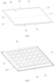
Fig.1 is an assembled perspective view of a panel light provided by an embodiment of the application when being laid flat for display; -
Fig.2 is an assembled perspective view of the panel light ofFig.1 when being in a normal use state; -
Fig.3 is an exploded perspective view of the panel light ofFig.2 ; -
Fig.4 is an enlarged view of part B inFig.3 ; -
Fig.5 is a perspective structural view of the base plate in the panel light ofFig.3 ; -
Fig.6 is a partial cross-sectional view along line A-A inFig.1 ; and -
Fig.7 is a schematic view showing the deformation of the diffuser plate in the panel light ofFig.1 . - In order to make the technical problems to be solved, technical solutions and beneficial effects of this application more comprehensible, the present disclosure is further described in detail below with reference to the accompanying drawings and embodiments. It is understood that the specific embodiments described herein are merely illustrative of the present application and are not intended to limit the present application.
- In the description of the embodiments of the present application, it should be understood that the terms "length", "width", "upper", "lower", "front", "rear", "left", "right", "vertical", "horizontal", "top", "bottom", "inner", "outer" and other directions or positional relationships are based on the directions or positional relationships shown in the drawings, which are merely used for facilitating description of embodiments and simplifying the description, without indicating or implying that the referred device or element must have a specific orientation, be constructed and operated in a specific orientation, and therefore cannot be understood as a limitation to the embodiments of the present application. In the description of the present application, "a plurality of" means two or more than two, unless specifically defined otherwise.
- In the embodiments of the present application, unless clearly specified and defined otherwise, the terms "install", "connection", "connect", "fix" and so on should be understood in a broad sense. For example, it may be a fixed connection, a detachable connection, or an integrated connection; it may be mechanical connection or electrical connection; it may be directly connected or indirectly connected through an intermediate medium, and it may be an internal communication of two components or an interaction relationship between two components. For those of ordinary skill in the art, the specific meanings of the above-mentioned terms in the embodiments of the present application can be understood according to specific circumstances.
- In a conventional panel light, a frame is used to fix a diffuser plate and a base plate, and the diffuser plate is clamped between the frame and the base plate. The conventional panel light when being laid flat for display, the diffuser plate is disposed upward, and the diffuser plate has a sag phenomenon by gravity. The closer the diffuser plate sags to the light source, the closer it gets to the light source assembly, then the panel light may create a light pattern in Tic-Tac-shaped, and thus the optical quality cannot meet the requirements.
- Please refer to
FIGS. 1 to 3 , an embodiment of the present application provides a panel light, which includes aframe 10, adiffuser plate 20, abase plate 30 and alight source assembly 40. With reference toFig.4 , theframe 10 has anannular retaining rim 11, andribs 12 are provided on theannular retaining rim 11. With reference toFig.6 , thediffuser plate 20 has anouter surface 20a and aninner surface 20b opposite to each other, and an edge portion of theouter surface 20a of thediffuser plate 20 abuts against therib 12. Thebase plate 30 has anannular flange 31, an edge portion of thebase plate 30 is fixed to theframe 10, and theannular flange 31 abuts on an edge portion of theinner surface 20b of thediffuser plate 20, and the distance between a position where theannular flange 31 abuts on thediffuser plate 20 and a center of thediffuser plate 20 is smaller than the distance between a position where therib 12 abuts on thediffuser plate 20 and the center of thediffuser plate 20, so that thediffuser plate 20 bulges outwards. The center of thediffuser plate 20 can be understood as a center line passing through theouter surface 20a and theinner surface 20b of thediffuser plate 20. With reference toFig.3 , thelight source assembly 40 is installed on thebase plate 30, and a light-emitting side of thelight source assembly 40 face towards thediffuser plate 20. - Compared with the related arts, in the panel light provided by the present application, the
ribs 12 are provided on the annular retaining rim 11 of theframe 10 that can increase the strength of theframe 10. As shown inFigs. 6 and 7 , during assembling, the edge portion of theouter surface 20a of thediffuser plate 20 abuts against therib 12, theannular flange 31 of thebase plate 30 abuts against the edge portion of theinner surface 20b of thediffuser plate 20, and the edge portion of thebase plate 30 is fixed to theframe 10. Since the pressure F1 of theannular flange 31 of thebase plate 30 on thediffuser plate 20 and the pressure F2 of therib 12 on thediffuser plate 20 are in opposite directions, the distance between a position where theannular flange 31 abuts on thediffuser plate 20 and a center of thediffuser plate 20 is smaller than the distance between a position where therib 12 abuts on thediffuser plate 20 and the center of thediffuser plate 20, so that thediffuser plate 20 may bulge outwards. InFigs. 6 and 7 , shown as bulge upwards, thereby increasing the strength of thediffuser plate 20, the deformation of thediffuser plate 20 when the panel light being in a normal use state or being laid flat for display is relatively small, and the sag phenomenon of thediffuser plate 20 by gravity is reduced, such that the distance between thelight source assembly 40 and thediffuser plate 20 is within a predetermined range, thereby the output light pattern can be relatively uniform when being in the normal use state or being laid flat for display, the difference is small, and the optical quality is improved - Among them, the
diffuser plate 20 may be made of PC (polycarbonate), PS (polystyrene) or PP (polypropylene). Thebase plate 30 may be formed by a process of sheet metal stamping and spraying, which is easy to manufacture and is beneficial to increase the strength of thebase plate 30. Thebase plate 30 has aninner cavity 33, and thelight source assembly 40 may be disposed on an inner bottom surface of thebase plate 30. - Exemplarily, with the
ribs 12 being provided on the annular retaining rim 11 of theframe 10, the edge portion of theouter surface 20a of thediffuser plate 20 abuts against theribs 12 during assembly, and theannular flange 31 of thebase plate 30 abuts against the edge portion of theinner surface 20b of thediffuser plate 20, such that the middle portion of thediffuser plate 20 bulges outwards, and the sag of thediffuser plate 20 can be reduced by about 5mm, this improves light emitting angles of the light source, reduces the overall height of the lamp, and the output light pattern of the panel light is relatively uniform. - In conventional panel lights, for diffuser plates of different thicknesses, the thinner diffuser plates have lower strength and there may be more obvious sagging. For diffuser plates of different materials, the diffuser plates made of PP and PC will sag more obviously than the diffuser plates made of PS. For diffuser plates of different sizes, the larger the length to width ratio of the diffuser plate, the more obvious the sagging.
- The panel light of this embodiment can adapt to
diffuser plates 20 of different sizes, thicknesses, materials and length-to-width ratios, so that the middle portion of thediffuser plate 20 assembled between theframe 10 and thebase plate 30 will bulge outward, thereby realizing an adjustment to the shape of thediffuser plate 20. In this way, the material and thickness of thediffuser plate 20 can be changed, there may be more choices and thus the material cost can be reduced. - Please refer to
Fig.2 andFig.3 , in another embodiment of the present application, theframe 10 has a square, circular, elliptical or triangular shape or other shapes, which can be specifically set as required. The annular retaining rim 11 of theframe 10 and theannular flange 31 of thebase plate 30 may be a circular, elliptical, square, rounded square structure or other annular structures, which can be specifically set as required. Exemplarily, theframe 10 is square, and the annular retaining rim 11 is also square, correspondingly, the outer edges of thediffuser plate 20 and thebase plate 30 are also square. - Referring to
Fig.3 , in another embodiment of the present application, theframe 10 includes a plurality ofprofiles 13, which are arranged in a ring shape, which facilitates the production of a plurality ofprofiles 13, and then form oneprofile 13 by an assembly. Theframe 10 can be made of aluminum profiles or other metal profiles. Exemplarily, theframe 10 has a square shape, fourprofiles 13 are provided, and the fourprofiles 13 enclose together to form asquare frame 10. It is understandable that theframe 10 may also be an integrally formed structure. - Please refer to
Figures 4 and6 , in another embodiment of the present application, the outer edge of theframe 10 has anannular boss 14, and an annular limitinggroove 15 may be formed between an inner wall of theannular boss 14 and theannular retaining rim 11, Theannular flange 31 may be accommodated in the annular limitinggroove 15; the edge portion of thebase plate 30 may be fixed to theannular boss 14. Theannular boss 14 is provided to facilitate the assembly of thebase plate 30. During assembling, theannular flange 31 of thebase plate 30 is disposed in the annular limitinggroove 15, and the edge portion of thebase plate 30 will be aligned with theannular boss 14 of theframe 10, such that the assembly efficiency can be improved. - Please refer to
Fig.6 . According to the invention, the edge portion of thebase plate 30 and theframe 10 are connected through afastener 50. Thebase plate 30 can be securely attached to theframe 10 with thefastener 50. Thefastener 50 is a screw, the screw passes through the edge portion of thebase plate 30 and is threaded to theframe 10, thereby achieving the assembly. - Please refer to
Fig.4 andFig.6 . In another embodiment of the present application, the cross section of theribs 12 may be square, triangular, trapezoidal, semicircular or other shapes, which can be specifically set as required. When therib 12 is provided with a triangular cross-sectional structure, a triangular slope of theribs 12 is close to the inner edge of theframe 10. When thediffuser plate 20 is assembled to theframe 10, the slope surface of theribs 12 abuts against the edge portion of theouter surface 20a of thediffuser plate 20, such that the stress can be evenly distributed on thediffuser plate 20, thediffuser plate 20 has better strength, and the amount of deformation of thediffuser plate 20 is smaller when it is displayed flat or in a normal use state. - Please refer to
Figs.4 and6 , in another embodiment of the present application, theribs 12 are arranged in a circle around the inner edge of theframe 10. When theribs 12 abut against the edge portion of theouter surface 20a of thediffuser plate 20, with theannular flange 31 of thebase plate 30 abuts against theinner surface 20b of thediffuser plate 20, thediffuser plate 20 can be deformed, and the middle portion of thediffuser plate 20 protrudes outward. - According to the invention, the
ribs 12 are also arranged in multiple sections, and theribs 12 with multiple sections are distributed on theframe 10 in an annular manner. When theribs 12 abut on the edge portion of theouter surface 20a of thediffuser plate 20, with theannular flange 31 of thebase plate 30 abuts against theinner surface 20b of thediffuser plate 20,thediffuser plate 20 can also be deformed to a certain extent, and the middle portion of thediffuser plate 20 protrudes outward. - Please refer to
Figs.3 and5 , in another embodiment of the present application, thebase plate 30 has a plurality ofpositioning grooves 32, the number oflight source assembly 40 is multiple, and thelight source assembly 40 are respectively arranged indifferent positioning grooves 32, this facilitates the positioning and installation of thelight source assembly 40. Exemplarily, thepositioning grooves 32 are strip-shaped and arranged at intervals, and thelight source assemblies 40 are strip-shaped that facilitates the installation of thelight source assembly 40 at different positions, so as to dissipate heat from the multiplelight source assemblies 40 and improve the heat dissipation effect. - Please refer to
Fig.3 , in another embodiment of the present application, thelight source assembly 40 includes asubstrate 41 andLED lamp beads 42 disposed on thesubstrate 41. Thesubstrate 41 is disposed on thebase plate 30, and theLED lamp beads 42 are disposed toward thediffuser plate 20. In this way, it is easy to manufacture thelight source assembly 40, thereby facilitating the heat generated by thelight source assembly 40 to diffuse from thebase plate 30 to the external environment. - Please refer to
Fig.3 , in another embodiment of the present application, the panel light further includes a driving assembly (not shown) being electrically connected with thelight source assembly 40. The driving assembly is used to convert the external power source into the power required by thelight source assembly 40 and drive thelight source assembly 40 to work. The driving assembly is arranged outside thebase plate 30 to reduce the possibility of the heat generated by thelight source assembly 40 being diffused to the driving assembly, and to improve the reliability of the lamp. The above are merely preferred embodiments of this application and are not intended to limit this application.
Claims (9)
- A panel light, comprising:a frame (10),a diffuser plate (20) having an outer surface (20a) and an inner surface (20b) opposite to each other,a base plate (30), anda light source assembly (40) configured to be installed on the base plate (30), and a light-emitting side of the light source assembly (40) face towards the diffuser plate (20);whereinthe frame (10) has an annular retaining rim (11), and ribs (12) are provided on the annular retaining rim (11); and an edge portion of the outer surface (20a) of the diffuser plate (20) is configured to abut against the ribs (12);the base plate (30) has an annular flange (31), an edge portion of the base plate (30) is fixed to the frame (10), and the annular flange (31) is configured to abut on an edge portion of the inner surface (20b) of the diffuser plate (20),the ribs (10) are arranged in multiple sections, and the ribs (10) with multiple sections are distributed on the frame (10) in an annular manner;the edge portion of the base plate (30) and the frame (10) are connected through fasteners (50);the fasteners (50) are screws that pass through the edge portion of the base plate (30) and are threaded to the frame (10);characterized in that the distance between a position where the annular flange (31) abuts on the diffuser plate (20) and a center of the diffuser plate (20) is smaller than the distance between a position where the ribs (12) abut on the diffuser plate (20) and the center of the diffuser plate (20), so that the diffuser plate (20) bulges outwards.
- The panel light according to claim 1, characterized in that, the frame (10) comprises a plurality of profiles (13), and the profiles (13) are arranged in an annular manner; or the frame (10) is configured to be an integrally formed structure.
- The panel light according to claim 1 or claim 2, characterized in that, an outer edge of the frame (10) has an annular boss (14), and an annular limiting groove (15) is formed between an inner wall of the annular boss (14) and the annular retaining rim (11), the annular flange (31) is accommodated in the annular limiting groove (15); the edge portion of the base plate (30) is fixed to the annular boss (14).
- The panel light according to any one of claim 1 to 3, characterized in that, a cross-section of the ribs (12) is square, triangular, trapezoidal or semicircular.
- The panel light according to any one of claims 1 to 4, characterized in that, the ribs (12) are arranged in a circle around an inner edge of the frame (10); or the ribs (12) are arranged in multiple sections, and the multiple sections of the ribs (12) are distributed on the frame (10) in an annular manner.
- The panel light according to any one of claims 1 to 4, characterized in that, the base plate (30) has a plurality of positioning grooves (32), the number of the light source assembly (40) is multiple, and the light source assembly (40) are respectively arranged in different positioning grooves (32).
- The panel light according to any one of claims 1 to 4, characterized in that, the light source assembly (40) comprises a substrate (41) and LED lamp beads (42) arranged on the substrate (41), the substrate (41) is arranged on the base plate (30), and the LED lamp beads (42) are arranged toward the diffuser plate (20).
- The panel light according to any one of claims 1 to 4, characterized in that, the panel light further comprises a driving assembly, and the driving assembly is electrically connected with the light source assembly (40).
- The panel light according to any one of claims 1 to 4, characterized in that, the frame (10) is square, circular, oval or triangular.
Applications Claiming Priority (1)
| Application Number | Priority Date | Filing Date | Title |
|---|---|---|---|
| CN202021171549.4U CN212390198U (en) | 2020-06-22 | 2020-06-22 | Panel light |
Publications (2)
| Publication Number | Publication Date |
|---|---|
| EP3929483A1 EP3929483A1 (en) | 2021-12-29 |
| EP3929483B1 true EP3929483B1 (en) | 2024-11-06 |
Family
ID=72422051
Family Applications (1)
| Application Number | Title | Priority Date | Filing Date |
|---|---|---|---|
| EP20194116.8A Active EP3929483B1 (en) | 2020-06-22 | 2020-09-02 | Panel light |
Country Status (2)
| Country | Link |
|---|---|
| EP (1) | EP3929483B1 (en) |
| CN (1) | CN212390198U (en) |
Families Citing this family (1)
| Publication number | Priority date | Publication date | Assignee | Title |
|---|---|---|---|---|
| CN218327615U (en) * | 2022-09-09 | 2023-01-17 | 惠州市晶辉科技有限公司 | An integrated lamp panel surface frame and an integrated panel lamp without a surface frame |
Citations (1)
| Publication number | Priority date | Publication date | Assignee | Title |
|---|---|---|---|---|
| EP2631536B1 (en) * | 2012-02-23 | 2018-04-11 | LG Innotek Co., Ltd. | Illumination unit and display apparatus using the same |
Family Cites Families (5)
| Publication number | Priority date | Publication date | Assignee | Title |
|---|---|---|---|---|
| CN201827785U (en) * | 2010-11-01 | 2011-05-11 | 北京京东方光电科技有限公司 | Back light source and liquid crystal display |
| CN205316166U (en) * | 2016-01-11 | 2016-06-15 | 佛山市柯迅照明电气有限公司 | Flat plate light |
| CN205807313U (en) * | 2016-06-29 | 2016-12-14 | 中山市华艺灯饰照明股份有限公司 | Flat light non-rigid locking structure |
| CN206958632U (en) * | 2017-07-21 | 2018-02-02 | 广州美谷电子科技有限公司 | A kind of straight light emitting plane lamp |
| CN210398468U (en) * | 2019-07-31 | 2020-04-24 | 佛山皇光照明电器有限公司 | Screw-free direct-lighting panel lamp |
-
2020
- 2020-06-22 CN CN202021171549.4U patent/CN212390198U/en active Active
- 2020-09-02 EP EP20194116.8A patent/EP3929483B1/en active Active
Patent Citations (1)
| Publication number | Priority date | Publication date | Assignee | Title |
|---|---|---|---|---|
| EP2631536B1 (en) * | 2012-02-23 | 2018-04-11 | LG Innotek Co., Ltd. | Illumination unit and display apparatus using the same |
Also Published As
| Publication number | Publication date |
|---|---|
| CN212390198U (en) | 2021-01-22 |
| EP3929483A1 (en) | 2021-12-29 |
Similar Documents
| Publication | Publication Date | Title |
|---|---|---|
| US7481569B2 (en) | Direct type backlight module | |
| US9989204B2 (en) | Substrate tensioning systems | |
| US11435061B2 (en) | Direct-type panel lamp | |
| CN217441545U (en) | Panel light | |
| US11927843B2 (en) | Backlight module and display device | |
| CN205402421U (en) | Straight down type backlight module and display device provided with same | |
| CN207455351U (en) | Illuminator and light source module group | |
| EP2560042B1 (en) | Backlight unit and lighting system including the same | |
| US8388181B2 (en) | Light source assembly using light emitting diodes and reflective sheet set | |
| US20110069251A1 (en) | Liquid crystal display device, backlight module, and method of assembling a backlight module | |
| CN210835512U (en) | Display device and backlight module thereof | |
| EP3929483A1 (en) | Panel light | |
| CN109764286A (en) | A direct type luminous panel light | |
| CN213983262U (en) | Direct type panel light | |
| KR20200085131A (en) | Slim typed led lighting | |
| CN216280966U (en) | Mounting structure of panel light | |
| US20230408866A1 (en) | Backlight module and curved display device | |
| CN213983264U (en) | Direct type panel light | |
| CN213983266U (en) | Direct type panel light | |
| CN216387674U (en) | Backlight module and display device | |
| CN102519018B (en) | Module assembly structure | |
| CN211040873U (en) | Light projector | |
| US8654277B2 (en) | Liquid crystal display module, backlight module and back plate thereof | |
| CN216952917U (en) | Full-luminous direct type panel lamp | |
| CN217684790U (en) | Panel light |
Legal Events
| Date | Code | Title | Description |
|---|---|---|---|
| PUAI | Public reference made under article 153(3) epc to a published international application that has entered the european phase |
Free format text: ORIGINAL CODE: 0009012 |
|
| STAA | Information on the status of an ep patent application or granted ep patent |
Free format text: STATUS: REQUEST FOR EXAMINATION WAS MADE |
|
| 17P | Request for examination filed |
Effective date: 20200902 |
|
| AK | Designated contracting states |
Kind code of ref document: A1 Designated state(s): AL AT BE BG CH CY CZ DE DK EE ES FI FR GB GR HR HU IE IS IT LI LT LU LV MC MK MT NL NO PL PT RO RS SE SI SK SM TR |
|
| B565 | Issuance of search results under rule 164(2) epc |
Effective date: 20210226 |
|
| STAA | Information on the status of an ep patent application or granted ep patent |
Free format text: STATUS: EXAMINATION IS IN PROGRESS |
|
| 17Q | First examination report despatched |
Effective date: 20220601 |
|
| GRAP | Despatch of communication of intention to grant a patent |
Free format text: ORIGINAL CODE: EPIDOSNIGR1 |
|
| STAA | Information on the status of an ep patent application or granted ep patent |
Free format text: STATUS: GRANT OF PATENT IS INTENDED |
|
| RIC1 | Information provided on ipc code assigned before grant |
Ipc: F21Y 105/00 20160101ALN20240308BHEP Ipc: F21Y 115/10 20160101ALN20240308BHEP Ipc: F21Y 103/10 20160101ALN20240308BHEP Ipc: F21V 17/12 20060101ALI20240308BHEP Ipc: F21V 15/01 20060101ALI20240308BHEP Ipc: F21V 3/06 20180101AFI20240308BHEP |
|
| INTG | Intention to grant announced |
Effective date: 20240404 |
|
| GRAS | Grant fee paid |
Free format text: ORIGINAL CODE: EPIDOSNIGR3 |
|
| GRAA | (expected) grant |
Free format text: ORIGINAL CODE: 0009210 |
|
| STAA | Information on the status of an ep patent application or granted ep patent |
Free format text: STATUS: THE PATENT HAS BEEN GRANTED |
|
| AK | Designated contracting states |
Kind code of ref document: B1 Designated state(s): AL AT BE BG CH CY CZ DE DK EE ES FI FR GB GR HR HU IE IS IT LI LT LU LV MC MK MT NL NO PL PT RO RS SE SI SK SM TR |
|
| REG | Reference to a national code |
Ref country code: GB Ref legal event code: FG4D |
|
| REG | Reference to a national code |
Ref country code: CH Ref legal event code: EP |
|
| REG | Reference to a national code |
Ref country code: DE Ref legal event code: R096 Ref document number: 602020040702 Country of ref document: DE |
|
| REG | Reference to a national code |
Ref country code: IE Ref legal event code: FG4D |
|
| REG | Reference to a national code |
Ref country code: LT Ref legal event code: MG9D |
|
| REG | Reference to a national code |
Ref country code: NL Ref legal event code: MP Effective date: 20241106 |
|
| PG25 | Lapsed in a contracting state [announced via postgrant information from national office to epo] |
Ref country code: HR Free format text: LAPSE BECAUSE OF FAILURE TO SUBMIT A TRANSLATION OF THE DESCRIPTION OR TO PAY THE FEE WITHIN THE PRESCRIBED TIME-LIMIT Effective date: 20241106 Ref country code: PT Free format text: LAPSE BECAUSE OF FAILURE TO SUBMIT A TRANSLATION OF THE DESCRIPTION OR TO PAY THE FEE WITHIN THE PRESCRIBED TIME-LIMIT Effective date: 20250306 Ref country code: IS Free format text: LAPSE BECAUSE OF FAILURE TO SUBMIT A TRANSLATION OF THE DESCRIPTION OR TO PAY THE FEE WITHIN THE PRESCRIBED TIME-LIMIT Effective date: 20250306 |
|
| PG25 | Lapsed in a contracting state [announced via postgrant information from national office to epo] |
Ref country code: FI Free format text: LAPSE BECAUSE OF FAILURE TO SUBMIT A TRANSLATION OF THE DESCRIPTION OR TO PAY THE FEE WITHIN THE PRESCRIBED TIME-LIMIT Effective date: 20241106 Ref country code: NL Free format text: LAPSE BECAUSE OF FAILURE TO SUBMIT A TRANSLATION OF THE DESCRIPTION OR TO PAY THE FEE WITHIN THE PRESCRIBED TIME-LIMIT Effective date: 20241106 |
|
| REG | Reference to a national code |
Ref country code: AT Ref legal event code: MK05 Ref document number: 1739693 Country of ref document: AT Kind code of ref document: T Effective date: 20241106 |
|
| PG25 | Lapsed in a contracting state [announced via postgrant information from national office to epo] |
Ref country code: BG Free format text: LAPSE BECAUSE OF FAILURE TO SUBMIT A TRANSLATION OF THE DESCRIPTION OR TO PAY THE FEE WITHIN THE PRESCRIBED TIME-LIMIT Effective date: 20241106 |
|
| PG25 | Lapsed in a contracting state [announced via postgrant information from national office to epo] |
Ref country code: ES Free format text: LAPSE BECAUSE OF FAILURE TO SUBMIT A TRANSLATION OF THE DESCRIPTION OR TO PAY THE FEE WITHIN THE PRESCRIBED TIME-LIMIT Effective date: 20241106 |
|
| PG25 | Lapsed in a contracting state [announced via postgrant information from national office to epo] |
Ref country code: NO Free format text: LAPSE BECAUSE OF FAILURE TO SUBMIT A TRANSLATION OF THE DESCRIPTION OR TO PAY THE FEE WITHIN THE PRESCRIBED TIME-LIMIT Effective date: 20250206 |
|
| PG25 | Lapsed in a contracting state [announced via postgrant information from national office to epo] |
Ref country code: LV Free format text: LAPSE BECAUSE OF FAILURE TO SUBMIT A TRANSLATION OF THE DESCRIPTION OR TO PAY THE FEE WITHIN THE PRESCRIBED TIME-LIMIT Effective date: 20241106 Ref country code: GR Free format text: LAPSE BECAUSE OF FAILURE TO SUBMIT A TRANSLATION OF THE DESCRIPTION OR TO PAY THE FEE WITHIN THE PRESCRIBED TIME-LIMIT Effective date: 20250207 Ref country code: AT Free format text: LAPSE BECAUSE OF FAILURE TO SUBMIT A TRANSLATION OF THE DESCRIPTION OR TO PAY THE FEE WITHIN THE PRESCRIBED TIME-LIMIT Effective date: 20241106 |
|
| PG25 | Lapsed in a contracting state [announced via postgrant information from national office to epo] |
Ref country code: PL Free format text: LAPSE BECAUSE OF FAILURE TO SUBMIT A TRANSLATION OF THE DESCRIPTION OR TO PAY THE FEE WITHIN THE PRESCRIBED TIME-LIMIT Effective date: 20241106 |
|
| PG25 | Lapsed in a contracting state [announced via postgrant information from national office to epo] |
Ref country code: RS Free format text: LAPSE BECAUSE OF FAILURE TO SUBMIT A TRANSLATION OF THE DESCRIPTION OR TO PAY THE FEE WITHIN THE PRESCRIBED TIME-LIMIT Effective date: 20250206 |
|
| PG25 | Lapsed in a contracting state [announced via postgrant information from national office to epo] |
Ref country code: SM Free format text: LAPSE BECAUSE OF FAILURE TO SUBMIT A TRANSLATION OF THE DESCRIPTION OR TO PAY THE FEE WITHIN THE PRESCRIBED TIME-LIMIT Effective date: 20241106 |
|
| PG25 | Lapsed in a contracting state [announced via postgrant information from national office to epo] |
Ref country code: DK Free format text: LAPSE BECAUSE OF FAILURE TO SUBMIT A TRANSLATION OF THE DESCRIPTION OR TO PAY THE FEE WITHIN THE PRESCRIBED TIME-LIMIT Effective date: 20241106 |
|
| PG25 | Lapsed in a contracting state [announced via postgrant information from national office to epo] |
Ref country code: EE Free format text: LAPSE BECAUSE OF FAILURE TO SUBMIT A TRANSLATION OF THE DESCRIPTION OR TO PAY THE FEE WITHIN THE PRESCRIBED TIME-LIMIT Effective date: 20241106 |
|
| PGFP | Annual fee paid to national office [announced via postgrant information from national office to epo] |
Ref country code: FR Payment date: 20250626 Year of fee payment: 6 |
|
| PG25 | Lapsed in a contracting state [announced via postgrant information from national office to epo] |
Ref country code: RO Free format text: LAPSE BECAUSE OF FAILURE TO SUBMIT A TRANSLATION OF THE DESCRIPTION OR TO PAY THE FEE WITHIN THE PRESCRIBED TIME-LIMIT Effective date: 20241106 |
|
| PG25 | Lapsed in a contracting state [announced via postgrant information from national office to epo] |
Ref country code: SK Free format text: LAPSE BECAUSE OF FAILURE TO SUBMIT A TRANSLATION OF THE DESCRIPTION OR TO PAY THE FEE WITHIN THE PRESCRIBED TIME-LIMIT Effective date: 20241106 |
|
| PG25 | Lapsed in a contracting state [announced via postgrant information from national office to epo] |
Ref country code: CZ Free format text: LAPSE BECAUSE OF FAILURE TO SUBMIT A TRANSLATION OF THE DESCRIPTION OR TO PAY THE FEE WITHIN THE PRESCRIBED TIME-LIMIT Effective date: 20241106 |
|
| PG25 | Lapsed in a contracting state [announced via postgrant information from national office to epo] |
Ref country code: IT Free format text: LAPSE BECAUSE OF FAILURE TO SUBMIT A TRANSLATION OF THE DESCRIPTION OR TO PAY THE FEE WITHIN THE PRESCRIBED TIME-LIMIT Effective date: 20241106 |
|
| REG | Reference to a national code |
Ref country code: DE Ref legal event code: R097 Ref document number: 602020040702 Country of ref document: DE |
|
| PG25 | Lapsed in a contracting state [announced via postgrant information from national office to epo] |
Ref country code: SE Free format text: LAPSE BECAUSE OF FAILURE TO SUBMIT A TRANSLATION OF THE DESCRIPTION OR TO PAY THE FEE WITHIN THE PRESCRIBED TIME-LIMIT Effective date: 20241106 |
|
| PLBE | No opposition filed within time limit |
Free format text: ORIGINAL CODE: 0009261 |
|
| STAA | Information on the status of an ep patent application or granted ep patent |
Free format text: STATUS: NO OPPOSITION FILED WITHIN TIME LIMIT |
|
| PGFP | Annual fee paid to national office [announced via postgrant information from national office to epo] |
Ref country code: DE Payment date: 20250627 Year of fee payment: 6 |
|
| 26N | No opposition filed |
Effective date: 20250807 |
|
| PGFP | Annual fee paid to national office [announced via postgrant information from national office to epo] |
Ref country code: GB Payment date: 20250703 Year of fee payment: 6 |
|
| REG | Reference to a national code |
Ref country code: CH Ref legal event code: H13 Free format text: ST27 STATUS EVENT CODE: U-0-0-H10-H13 (AS PROVIDED BY THE NATIONAL OFFICE) Effective date: 20260504 |