EP3929479A1 - Switchless valve position detection system - Google Patents
Switchless valve position detection system Download PDFInfo
- Publication number
- EP3929479A1 EP3929479A1 EP21180479.4A EP21180479A EP3929479A1 EP 3929479 A1 EP3929479 A1 EP 3929479A1 EP 21180479 A EP21180479 A EP 21180479A EP 3929479 A1 EP3929479 A1 EP 3929479A1
- Authority
- EP
- European Patent Office
- Prior art keywords
- valve
- current
- driver
- controller
- opening
- Prior art date
- Legal status (The legal status is an assumption and is not a legal conclusion. Google has not performed a legal analysis and makes no representation as to the accuracy of the status listed.)
- Pending
Links
Images










Classifications
-
- F—MECHANICAL ENGINEERING; LIGHTING; HEATING; WEAPONS; BLASTING
- F16—ENGINEERING ELEMENTS AND UNITS; GENERAL MEASURES FOR PRODUCING AND MAINTAINING EFFECTIVE FUNCTIONING OF MACHINES OR INSTALLATIONS; THERMAL INSULATION IN GENERAL
- F16K—VALVES; TAPS; COCKS; ACTUATING-FLOATS; DEVICES FOR VENTING OR AERATING
- F16K37/00—Special means in or on valves or other cut-off apparatus for indicating or recording operation thereof, or for enabling an alarm to be given
- F16K37/0025—Electrical or magnetic means
- F16K37/0041—Electrical or magnetic means for measuring valve parameters
-
- F—MECHANICAL ENGINEERING; LIGHTING; HEATING; WEAPONS; BLASTING
- F16—ENGINEERING ELEMENTS AND UNITS; GENERAL MEASURES FOR PRODUCING AND MAINTAINING EFFECTIVE FUNCTIONING OF MACHINES OR INSTALLATIONS; THERMAL INSULATION IN GENERAL
- F16K—VALVES; TAPS; COCKS; ACTUATING-FLOATS; DEVICES FOR VENTING OR AERATING
- F16K31/00—Actuating devices; Operating means; Releasing devices
- F16K31/02—Actuating devices; Operating means; Releasing devices electric; magnetic
- F16K31/04—Actuating devices; Operating means; Releasing devices electric; magnetic using a motor
-
- F—MECHANICAL ENGINEERING; LIGHTING; HEATING; WEAPONS; BLASTING
- F16—ENGINEERING ELEMENTS AND UNITS; GENERAL MEASURES FOR PRODUCING AND MAINTAINING EFFECTIVE FUNCTIONING OF MACHINES OR INSTALLATIONS; THERMAL INSULATION IN GENERAL
- F16K—VALVES; TAPS; COCKS; ACTUATING-FLOATS; DEVICES FOR VENTING OR AERATING
- F16K31/00—Actuating devices; Operating means; Releasing devices
- F16K31/02—Actuating devices; Operating means; Releasing devices electric; magnetic
- F16K31/04—Actuating devices; Operating means; Releasing devices electric; magnetic using a motor
- F16K31/046—Actuating devices; Operating means; Releasing devices electric; magnetic using a motor with electric means, e.g. electric switches, to control the motor or to control a clutch between the valve and the motor
-
- F—MECHANICAL ENGINEERING; LIGHTING; HEATING; WEAPONS; BLASTING
- F16—ENGINEERING ELEMENTS AND UNITS; GENERAL MEASURES FOR PRODUCING AND MAINTAINING EFFECTIVE FUNCTIONING OF MACHINES OR INSTALLATIONS; THERMAL INSULATION IN GENERAL
- F16K—VALVES; TAPS; COCKS; ACTUATING-FLOATS; DEVICES FOR VENTING OR AERATING
- F16K37/00—Special means in or on valves or other cut-off apparatus for indicating or recording operation thereof, or for enabling an alarm to be given
- F16K37/0075—For recording or indicating the functioning of a valve in combination with test equipment
- F16K37/0083—For recording or indicating the functioning of a valve in combination with test equipment by measuring valve parameters
Definitions
- the present disclosure pertains to valves and control of valves.
- the disclosure reveals a valve without position indicating switches. Positions of the valve are detected from current magnitude measurements and current profile analytics.
- the current profile can be initially learned and relearned and adapted with each valve operation.
- the valve may be opened and closed by a driver that is actuated by an electrical current to control the opening and closing of the valve.
- the current may be regulated by a controller to open and close the valve appropriately.
- the present system and approach may incorporate one or more processors, computers, controllers, user interfaces, wireless and/or wire connections, and/or the like, in an implementation described and/or shownherein.
- This description may provide one or more illustrative and specific examples or ways of implementing the present system and approach. There may be numerous other examples or ways of implementing the system and approach.
- FIG. 1 is a basic diagram of a switchless valve control system 400.
- a valve 401 that is opened and closed by an electric valve moving driver 402.
- a controller 403 may provide power via lines 404 and 405 to driver 402.
- An ampere meter 409 may be connected in series with line 404 or is part of the controller 403.
- Meter 409 may have an output to a detection and/or analytics module 406 via connection 408 of a waveform of magnitude of current provided to driver 402.
- the detection and/or analytics module 406 canbe also part of the controller 403. From the waveform, detection module 406 can determine whether the valve is opening, is open, closing, is closed, or is at an intermediate position.
- Determinations of valve activity may be sent by detection module 406 via a connection 407 to controller 403 so as to provide appropriate control of valve 401 with current control via lines 404 and 405 to driver 402.
- Connections 407 and 408 may be wired or wireless.
- Controller 403 may incorporate a user interface. In other words, present system 400 maydetect valve positions, opened and closed, without switches by current measurement of, for example, a valve motor, and by driving the valve to a defined block position.
- a software algorithm which is parameterized to new valve performance of current and time, may have a learning algorithm in that these valve parameters can be adapted to later ageing and dust effects. This adaption maybe done smoothly to avoid the learning of failure modes.
- the system may remain robust for voltage and temperature differences and can detect abnormaltamper or blocking conditions.
- the current measurement may be done by existing components with the micro of the electronic index and so achieving a significant cost reduction by removing the switches from the printed circuit board assembly (PCBA) appearsfeasible.
- PCBA printed circuit board assembly
- the challenge minimizing the current valve version development is to recognize the valve position as well as the further possible states by the physical signals like time, current, voltage with the goal to remove the end position switches. As minimum requirement is to recognize the end positions, i.e., open and closed.
- a straight forward solution may be to detect the end position on a steep threshold of a current waveform. But this kind of detection alone may not be enough, because with respect to all known additional situations like ageing, tampering, environmental conditions, and so on, one needs to adapt a decision with maximum objectivity in comparison to a proper solution with the end position detectors realized by the hardware (HW), that provides geometrical position knowledge independent of the environmental conditions, tampering, and so on.
- Data generated or captured may include current values derived fromopening or closing a valve by a microelectronic assembly.
- a specification may show a valve module with a driver interface and no additional digital positioning detectors.
- the valve state may be recognized from physical characteristics detected by a software (SW) module in a microcontroller (uC).
- SW software
- uC microcontroller
- the present system is to recognize a valve position aswell as the further possible states by the physical signals like time, current, voltage with a goal to remove the end position switches.
- the system may recognize the end positions open and closed.
- the system may detect an end position on the steep threshold of the current.
- the valve position and interaction time may play a secondary role.
- the driver function mayprovide robust and clear diagnostic information.
- Production steps to be taken in account may be as follows. 1) The indexHW may be flashed and rebooted without the connected valve. 2) In the next step, the valve with a physically unknown position may be connected to the Index. 3) At this step, it should be needed to execute the learning procedure, with the goal to learn the valve HW parameters as well as bring the valve into a defined position. 4) The leakage test may be executed. The valve position maybe expected to be in the open state as a default state.
- the learning phase may have an initial connection the valve HW to the main board of the index or driver box HW.
- the driver HW does not necessarily have any knowledge about the current valve position following someinitial actions, or calibration steps.
- the simplest action needed for the initialization may be a "feeling" of the closing position and measurement of the operational mechanical distance over the time during the additional opening phase. As soon the "closed" end position is reached, the opening transition may be initiated. By driving up to the physical end position, the operation time may be tracked and stored as the initial operational time. This may be used to adapt the operational parametersin the field depending on the ageing processes.
- the learning phase for production and final in field operation options may be a little bit different in the sensitivity and diagnostic behavior. However, there may be an exchange of the configuration by changing some of the key parameters of the driver.
- the learning process may self-implement two significant phases.
- the driver may try to detect a proof end position for a close state.
- the operational time, up to this threshold may be irrelevant.
- Thefirmware may drive the valve as soon the maximum current consumption is detected.
- An error may state that can happen here in that there is only the "time_out" for an operation.
- the driver may start the moving in the opposite direction and measure the opening time until the hardcurrent threshold is detected.
- the measured opening time may be used as initializer for opening and closing observer variables.
- the new learned behavior parameters may be immediately valid and can be stored in the non- volatile memory.
- a typical current profile of a closing transition may have the following behavior during the closing transition as it is important to recognize the rapid current jump in any case as soon as possible for proper recognition of the endposition and immediately stopping the movement if an issue is detected of gasflow detection.
- Figure 2 may be noted as an example trace 301 of a valve closure.
- a typical current profile of the opening transition may have a picture as in Figure 3 of an example trace 302 of a valve during an opening transition. It is important to recognize the rapid current jump at any case as soon as possible in recognition of an end position within a ten percent tolerance in case of an issue while trying a closing or opening the valve.
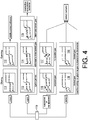
- Figure 4 is a diagram of various functional samples. With respect to safety and mechanical requirements, an optimal solution may be to implementan algorithm with end position detection on the raised current threshold at a closing stage and with a valve driver stopping on the estimated position during an opening transition.
- the diagram may provide a rough overview of expectedstates of a valve from a beginning of manufacturing up to functioning in the field with or without an impact of tampering or ageing.
- Waveforms of a driver 110 are shown in Figure 4 .
- Waveforms 111 show valve closing and waveforms 112 show a valve opening in view of stable correct behavior.
- Signal waveforms 113 show an aged or jammed function; and waveforms 114 show deformed or dirtied (defect) gear.
- Waveforms 115 show a deformed (defect) gear.
- Waveforms 113, 114 and 115 may have borderline acceptable behavior.
- Waveforms 116 are suspected of a tampered valve.
- Waveforms 117 are suspected of a manipulated valve.
- Waveforms 118 and 119 indicate a blocked valve revealing defective behavior. There may be load free running, that is, no grip in the gear, or a physical driver disconnection.
- an opening data set 305 shown in Figure 5 reveals the following significant process stages: Stage A) initial inertia overcoming; Stage B) tolerance compensation -- the driver is running nearly without the load; Stage C)spring compressing -- the effective mechanical moving phase -- the current is bit higher under real pressure conditions; and Stage D) end compression against the physical border.
- a closing data set 306 in Figure 6 reveals the following significant process stages: Stage A) initial inertia overcoming; Stage B)closing phase with support of the gas pressure and spring force -- The driver is running nearly without the load; and Stage C) end compression against the physical border.
- Figure 7 is a diagram of signals designated as: raw current 61 - the raw measured current value without any filter; avg 62 - current average value (discrete low pass filter); base current 63 - the geometrical average value buildfrom the start point of the measurement; avg/base 64 - the ratio between the current raw measured and the base current values; raw int 65 - the integrated raw current value; soll int 66 - the estimated energy consumption from the "golden device"; end pos 67 - raised threshold indicates the estimated action end position; and current monitor 68 - detection of the mechanical end positionon the driver current threshold.
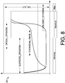
- a basic profile should be monitored by the controller which may be simplified by a diagram in Figure 8 , which is a diagram 251 showing a basic profile as monitored by a controller.
- Another part, a driver valve -- valve_drv may provide a piece ofcode for direct hardware control.
- Figure 9 is a diagram 252 showing a current consumption curve separated into several areas and corridors.
- the areas may be defined by an electrical current consumption value in dependency to a time related window.
- a middle area may indicate a nominal operational pattern. Any deviations ofthe corridor may lead to a related error log entry.
- the driver may be a simple current observer only. For a final decision,the current consumption information may be associated with related time information.
- Figure 10 may provide several scenarios during a valve interaction.
- a curve 46 may show a typical current flow by an intact valve hardware.
- a curve 42 may mark a typical position detection by a valve with endposition detection. So 41st, 43rd, 44th and 45th lines may present several tampering or jamming conditions.
- Last but not least the curve 47 may provide an unloaded driver operation.
- an interaction process call may be divided into the following sections on the lower portion of Figure 10 .
- a motor may start the driving.
- a process slot the whole opening or closing job may be executed.
- the time window within the abrupt raised current threshold, as an indication by the border may be detected.
- an error phase may be a time-out without the expected high current measurement as an indication of damage or an unexpected condition.
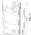
- the driver may implement some additional services to diagnose the valve state as well as manipulation attacks. Similar to a previous minimal implementation concept, a diagram of Figure 11 may provide curves 55 and 56as a typical current flow by an intact valve hardware. The 51st, 52nd, 53rd and54 lines may present several tampering or jamming conditions. Lastly, a curve57 may provide an unloaded driver operation.
- a valve driver may implement the observation slots and following diagnostic functions.
- the motor may start the driving, and the current profile may be monitored. In case of an unexpected high current consumption, this may provide an indication of damage/blockage.
- a first significant correction point may be recorded.
- current progress may be monitored. In case of an unexpected high current consumption, there may an indication of blockage/tampering.
- the second control point may be recorded.
- a comparison between first and second control points may provide information regarding the whole hardware "feeling". So the effort value at the second point may provide knowledge and a following correction factor for the following stage. This may also estimate an end time of the border event.
- An observation slot within the time window may allow detection of an abrupt raised current threshold. This event may be logged as a "transition successful”. The process may be successfully stopped with a logged message of "driver stopped”.
- the whole operational time may be separated into three slots: [MIN TIME, NOM_TIME, and MAX_TIME].
- the minimal time window: MIN_TIME may define the slot within no high consumption to be expected. If high current is detected, it may be a hint of possible ageing, manipulation or mechanical damage of the valve. In any case, this will be logged and stored into the log memory.
- NOM_TIME the expected end position may be measured. The window may be more or less dynamic and be adapted at everyclose or open action separately.
- the driver activity may be switched off, because this may be outside the expected "usual" process area. A related log event may be generated.
- the valve driver may take the state UNKNOWN independent of the real valve connection.
- the model does not necessarily expect any parametrization.
- the index may receive further commands for closing or opening and execute this but without proper state management. From this point on are existing two possibilities to provide proper operation to the valve driver.
- One may execute the learning process by writing a valve model configuration option to the HARDWARE_INFO object. This may be done at everytime (for execution conditions that refer to the object implementation, and for instance takes up to 20 sec. in the execution) or, second, execute the open -- close cycle for more such as four times. In this case, the driver may measure the HW conditions and learn that it is over several cycles for a stable operation. After successful execution of the recommended procedure (i) or (ii), the state may be stored into the nonvolatile memory and be used for a specified operation.
- the learning process may self-implement two significant phases or states.
- the driver may try to detect a proof end position for a close state.
- the operational time, up to this threshold may be irrelevant.
- the firmware may drive the valve as soon as the max current consumption is detected.
- the error state that may happen here, is only the "time_out” for operation.
- the driver may start moving in the opposite direction and measure the opening time until the hard current threshold is detected.
- the measured opening time may be used as an initializer for opening and closing observer variables.
- the new learned behavior parameters may be immediately valid and be stored in the nonvolatile memory.
- the new learned operational time may be adopted for the next opening and closing processes.
- the last learned "finger print' may be found in the VALVE_DRV_SETUP_CONTROL. This time may be directly coupled to the environmental conditions (operation under gas pressure or operation under anunloaded condition). The last means to rush condition change may lead to unwanted side effects and error events.
- Figure 12 is a flow diagram of a driver process with signals going from one functional block to another for opening and closing a valve.
- An idle block 71 may incorporate a "previous error_state”.
- a "statement logged” may go from block 71 to an active/movement block 72.
- a "diag_higher_consumption” may go from block 72 to a high current block 73.
- a “diag_unexpected_threshold” may go from block 72 to a stop_by_blocking block 74.
- a “timeout” may go from block 72 to a stop_by_timeout block 75.
- a “stop_condition; statement_logged_conditons_stored;” may go from block 72 toa relearning block 76.
- a “diag unexpected threshold” may go from block 73 toblock 74.
- a “stop condition; statement_logged conditions_stored;” may go from block 73 to block 76.
- a “diag unexpected threshold” may be from block 73 to block 74.
- a “statement logged; conditions_stored;” may go from block 74 to a reverse movement block 77.
- a “statement_logged; conditions_stored;” may go from block 75 to block 71.
- a “statement logged; conditions stored;” may go from block 76 to a valve position changed block 78.
- a “statement_logged; conditions stored; may go from block 77 to block 78.
- a “state changed;” may go from block 78 to block 71.
- Figure 13 is a diagram of a logic schematic.
- a block 11 may show a "reboot or 1 st connection” to a block 21 entitled “unexpected state 'blocking'”.
- a "voltage stability” block 12 may show a connection to a block 22 entitled “consumption is higher” and to a block 23 entitled “actions take longer”.
- a block 13 may show a "time monitoring” connected to block 21 entitled “unexpected state 'blocking', block 22 “consumption is higher”, block 23 entitled “actions take longer”, and a block 24 entitled “actions are faster”.
- a block 14 may show “aging” connected to block 23 entitled “actions take longer”.
- a block 15 may show "temperature variation” connected to block 23 entitled “actions take longer” and block 24 entitled “actions are faster”.
- Block 21 entitled “unexpected state 'blocking'", block 22 entitled “consumption is higher”, block 23 entitled “actions take longer” and block 24 entitled “actionsare faster” have outputs connected to a
- An output from “logic” block 20 may go to a "SW driver normal conditions” block 31, which may have outputs to a “blocking in action” block 32, “blocking at start” block 33, “defect_gear” block 34, and “interruption” block 35. Connections directly from “logic” block 20 may go directly to "blocking inaction” block 32 and “blocking at start” block 33.
- Another output from "SW driver normal conditions” block 31 may go to a block 36 where the current difference between the base current and average current is over a threshold limit. Block 36 may indicate the threshold as covered.
- a block 37 may indicate a current isover the alert-limit and a debouncing slot is exceeded.
- a block 38 encompassing block 34 and block 35, may indicate the current is under the alert-limit and a qualification time out is fired.
- Figure 14 is a diagram of regular operation logic for regular open/close processing.
- a start may begin at symbol 81 which can provide a signal to a closed symbol 82 and/or opened symbol 83.
- a signal may go to opened symbol 83.
- a signal may go from symbol 83 to a close_pre symbol 84 which in turn may provide a signal to close_nom 85.
- From symbol 85 a signal may go toclosed symbol 82.
- a signal may go from symbol 82 to open_presymbol 87.
- Toan open_nom symbol 88 may a signal be from symbol 87. From symbol 88, a signal may go to an opened symbol 83.
- a block 91 that contains symbol 87 and symbol 88, may provide a signal to a force_state (emergency close) symbol 93.
- a block 92 that contains symbol84 and symbol 85, may send a signal to symbol 93. From symbol 93 a signal may go to a defect symbol 94.
- a signal from block 92 may go to a time out symbol 95, interrupted symbol 96, blocked signal 97 and high load (manipulation/aging/and so on) symbol 98.
- a signal from block 91 may also go to symbol 95, symbol 96,symbol 97 and symbol 98.
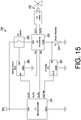
- FIG. 15 is a block diagram 200 of valve control electronics.
- the microcontroller U1 201 controls the valve driver U2 202 via IN1 and IN2 of the valve driver.
- IN1 and IN2 have high impedance, so the current in these pins is very low compared to the valve current to valve 203 from OUT1 and OUT2 of valve driver 202.
- the valve driver 202 controls the valve 203 via OUT1 and OUT2.
- Valve driver 202 pins OUT1 and OUT2 can have a high or low voltage.
- the valve driver 202 can control the direction of the motor of valve 203 by applying positive or negative voltage to the valve 203 motor.
- the valve current goes through the GND pin of the valvedriver 202 and the shunt resistor 204.
- the voltage drop at resistor 204 is proportional to the absolute value of the valve current.
- the microcontroller 201 measures the voltage drop at resistor 204 with its analog to digital converter via the ADC_IN pin of microcontroller 201.
- the ADC_IN pin has high impedance, so the current at this pin is very small compared to the valve 203 current.
- the microcontroller 201 sends a signal to the safety circuit 205.
- the safety circuit 205 controls the switch 206.
- the valve 203 can be operated only when the switch 206 is activated. This switch 206 prevents operation of the valve 203 in case of a failure.
- the HF-filter 207 filters high frequency noise from the shunt voltage across resistor 204. This improves the accuracy of the ADC measurements at ADC IN of microcontroller 201.
- Figure 16A is a diagram of an illustrative example present valve assembly 351.
- the diagram reveals a motor 352, gears 353 and gear rack 354.
- Figure16B shows valve assembly 351 with a protective cover 355. Also shown are locations of cutaways at positions A-A and B-B.
- Figure 16C is an A-A cutaway view of assembly 351. The view reveals a valve housing 357, valve cover 358,spring 359, valve disk 361, valve gasket 362 and valve body 363.
- a switchless valve control system may incorporate a driver for a mechanical connection to a valve and be configured to change a position of the valve, a controller electrically connected to the driver and be configured to electrically cause the driver to change the position of the valve, and a current sensor electrically connected to the driver so as to detect a profile of current from the controller in terms of magnitude going to the driver, to indicate a position of the valve.
- the system may further incorporate an analytics or detection module connected to or is a part of the controller, and connected to an output of the current sensor.
- the analytics module may identify a closing of the valve and an opening of the valve from the profile of current detected by the current sensor.
- a sensing of a closing and measurement of an operational mechanical distance overtime may occur during an additional opening phase of the valve.
- an opening transition may be initiated.
- a closing transition may be initiated.
- an operation time may betracked and stored as an initial operation time.
- the initial operation time may be for adapting operational parameters ofthe driver.
- a valve position driver apparatus may incorporate a valve driver, a controller having a power output for the valve driver, and a sensor connected to the controller for detecting current of the power output.
- the controller may detect closure and opening of a valve according to a magnitude of current provided to the valve driver system.
- the controller may be effected with a learning process.
- the driver may detect a proof end position for a closedstate.
- the controller may cause the driver to move a valve as soon as a maximum of current consumption is detected.
- the driver may start moving the valve in an opposite direction and measure an opening time until a threshold is detected.
- the driver may start moving the valve in anopposite direction and measure a closing time until a threshold is detected.
- a measured opening time may be usedas an initializer for opening and closing observer variables.
- Newly learned behavior parameters may be validated and stored in a non-volatile memory.
- a time of operation may incorporate multiple slots.
- the multiple slots may include a minimal time window, a nominal time window and a maximum time window.
- the minimal time window may define a slot where current consumption is abnormal, and if current higher or lower than normal in the slot is detected, then a problem with the valve may be noted and stored in a memory.
- the nominal time window may define a slot where a normal expected end position is measured and adapted at each close or open action.
- the maximum time window may define a slot where the driver is switched off since a duration ofthe slot is outside a normal process.
- a valve control mechanism may incorporate a valve driver, a controllerconnected to the valve driver, and a current meter connected in-line between the controller and the valve driver.
- the current meter may have an output indicating current magnitude, connected to the controller.
- the valve driver maybe connected to a valve and configured to open and close the valve.
- a current profile of the current magnitude of current used to power the valve driver may indicate openness and closure of the valve, or a physical condition of the valve.
- a start slot may be when a motor of the valve driver starts driving the valve, while the current profile is monitored.
- the mechanism may further incorporate a device configured to record consumption of current, connected to the controller.
- An unusual amount of consumption of current may indicate a functional discrepancy with the valve.
- the device may record a first control point of the unusual amount of consumption of current.
- a qualification slot may involve monitoring a progress of the current consumption and noting higher than usual current consumption at an end ofthe qualification slot.
- the device may record a second control point of the higher than usual current consumption.
- a comparison of the first and second control points may provideinformation leading to a correction factor for controlling the valve.
- An observation slot may have a time window which is allowed detection of an abrupt raised current threshold, an event that is logged in as a transitionsuccessful and provides information about a whole process that is used for a relearning operation in controlling the valve.
- New measured process data may be used at least partially as a calibration for the next action for controlling the valve.
Landscapes
- Engineering & Computer Science (AREA)
- General Engineering & Computer Science (AREA)
- Mechanical Engineering (AREA)
- Indication Of The Valve Opening Or Closing Status (AREA)
Abstract
Description
- The present disclosure pertains to valves and control of valves.
- The disclosure reveals a valve without position indicating switches. Positions of the valve are detected from current magnitude measurements and current profile analytics. The current profile can be initially learned and relearned and adapted with each valve operation. The valve may be opened and closed by a driver that is actuated by an electrical current to control the opening and closing of the valve. The current may be regulated by a controller to open and close the valve appropriately.
-
-
Figure 1 is a diagram of a basic switchless valve control system; -
Figure 2 is a diagram of an example trace of a valve closure; -
Figure 3 is a diagram of an example trace of a valve during an opening transition; -
Figure 4 is a diagram of signal waveforms of various functions of a driver;Figure 5 is a diagram of a data set for an opening phase of a valve; -
Figure 6 is a diagram of a data set for a closing phase of the valve;Figure 7 is a diagram of signals of various states of current to the driver; -
Figures 8 and9 are diagrams of basic profiles of current magnitude monitored by a controller; -
Figure 9 is a diagram showing a current consumption curve separatedinto several areas and corridors; -
Figure 10 is a diagram of several scenarios during a valve interaction; -
Figure 11 is a diagram of curves of a typical current flow by intact valvehardware; -
Figure 12 is a diagram of a driver process with signals going from one functional block to another for opening and closing a valve; -
Figure 13 is a diagram of a logic schematic for the driver and valvesystem operation; -
Figure 14 is a diagram of regular operation logic for regular valve open/close processing; -
Figure 15 is a diagram of valve system electronics; and -
Figures 16A-16C are diagrams of various aspects of an illustrative - The present system and approach may incorporate one or more processors, computers, controllers, user interfaces, wireless and/or wire connections, and/or the like, in an implementation described and/or shownherein.
- This description may provide one or more illustrative and specific examples or ways of implementing the present system and approach. There may be numerous other examples or ways of implementing the system and approach.
-
Figure 1 is a basic diagram of a switchlessvalve control system 400. There may be avalve 401 that is opened and closed by an electricvalve moving driver 402. Acontroller 403 may provide power vialines ampere meter 409 may be connected in series withline 404 or is part of thecontroller 403.Meter 409 may have an output to a detection and/oranalytics module 406 viaconnection 408 of a waveform of magnitude of current provided todriver 402. The detection and/oranalytics module 406 canbe also part of thecontroller 403. From the waveform,detection module 406
can determine whether the valve is opening, is open, closing, is closed, or is at
an intermediate position. Determinations of valve activity may be sent bydetection module 406 via aconnection 407 tocontroller 403 so as to provide appropriate control ofvalve 401 with current control vialines Connections Controller 403
may incorporate a user interface. In other words,present system 400 maydetect valve positions, opened and closed, without switches by current measurement of, for example, a valve motor, and by driving the valve to a defined block position. - A software algorithm, which is parameterized to new valve performance of current and time, may have a learning algorithm in that these valve parameters can be adapted to later ageing and dust effects. This adaption maybe done smoothly to avoid the learning of failure modes. The system may remain robust for voltage and temperature differences and can detect abnormaltamper or blocking conditions.
- The current measurement may be done by existing components with the micro of the electronic index and so achieving a significant cost reduction by removing the switches from the printed circuit board assembly (PCBA) appearsfeasible.
- Within the scope of the cost reduction, one may minimize the material costs of the system. The challenge minimizing the current valve version development is to recognize the valve position as well as the further possible states by the physical signals like time, current, voltage with the goal to remove the end position switches. As minimum requirement is to recognize the end positions, i.e., open and closed.
- A straight forward solution may be to detect the end position on a steep threshold of a current waveform. But this kind of detection alone may not be enough, because with respect to all known additional situations like ageing, tampering, environmental conditions, and so on, one needs to adapt a decision with maximum objectivity in comparison to a proper solution with the end
position detectors realized by the hardware (HW), that provides geometrical position knowledge independent of the environmental conditions, tampering, and so on. Data generated or captured may include current values derived fromopening or closing a valve by a microelectronic assembly. - A specification may show a valve module with a driver interface and no additional digital positioning detectors. The valve state may be recognized from physical characteristics detected by a software (SW) module in a microcontroller (uC). The present system is to recognize a valve position aswell as the further possible states by the physical signals like time, current, voltage with a goal to remove the end position switches. The system may
recognize the end positions open and closed. The system may detect an end position on the steep threshold of the current. But this alone may not be enough, because with respect to all known additional situations like ageing, tampering, environmental conditions, and so on, it may adapt a decision with maximum objectivity in comparison to a proper solution with the end position
detectors realized by the hardware (HW), that can provide geometrical position knowledge in dependence of the environmental conditions, tampering, and soforth. - One may need to act with a specific driver variant, and to track very sensitively the valve current during operation. The valve position and interaction time may play a secondary role. However, the driver function mayprovide robust and clear diagnostic information.
- Production steps to be taken in account may be as follows. 1) The indexHW may be flashed and rebooted without the connected valve. 2) In the next step, the valve with a physically unknown position may be connected to the
Index. 3) At this step, it should be needed to execute the learning procedure, with the goal to learn the valve HW parameters as well as bring the valve into a defined position. 4) The leakage test may be executed. The valve position maybe expected to be in the open state as a default state. - The learning phase may have an initial connection the valve HW to the main board of the index or driver box HW. In this case, the driver HW does not necessarily have any knowledge about the current valve position following someinitial actions, or calibration steps.
- The simplest action needed for the initialization may be a "feeling" of the closing position and measurement of the operational mechanical distance over the time during the additional opening phase. As soon the "closed" end position is reached, the opening transition may be initiated. By driving up to the physical end position, the operation time may be tracked and stored as the initial operational time. This may be used to adapt the operational parametersin the field depending on the ageing processes. The learning phase for
production and final in field operation options may be a little bit different in the sensitivity and diagnostic behavior. However, there may be an exchange of the configuration by changing some of the key parameters of the driver. - The learning process may self-implement two significant phases. In the first phase, the driver may try to detect a proof end position for a close state. In this phase, the operational time, up to this threshold may be irrelevant. Thefirmware may drive the valve as soon the maximum current consumption is detected. An error may state that can happen here in that there is only the "time_out" for an operation.
- As soon the "close" end position is reached the driver may start the moving in the opposite direction and measure the opening time until the hardcurrent threshold is detected. The measured opening time may be used as initializer for opening and closing observer variables. The new learned behavior parameters may be immediately valid and can be stored in the non- volatile memory.
- A typical current profile of a closing transition may have the following behavior during the closing transition as it is important to recognize the rapid current jump in any case as soon as possible for proper recognition of the endposition and immediately stopping the movement if an issue is detected of gasflow detection.
Figure 2 may be noted as anexample trace 301 of a valve
closure. - A typical current profile of the opening transition may have a picture as
inFigure 3 of anexample trace 302 of a valve during an opening transition. It is important to recognize the rapid current jump at any case as soon as possible in recognition of an end position within a ten percent tolerance in case of an
issue while trying a closing or opening the valve. -
Figure 4 is a diagram of various functional samples. With respect to safety and mechanical requirements, an optimal solution may be to implementan algorithm with end position detection on the raised current threshold at a closing stage and with a valve driver stopping on the estimated position during
an opening transition. The diagram may provide a rough overview of expectedstates of a valve from a beginning of manufacturing up to functioning in the field with or without an impact of tampering or ageing. - Signal waveforms of a
driver 110 are shown inFigure 4 .Waveforms 111 show valve closing andwaveforms 112 show a valve opening in view of stable correct behavior.Signal waveforms 113 show an aged or jammed function; andwaveforms 114 show deformed or dirtied (defect) gear.Waveforms 115 show a deformed (defect) gear.Waveforms Waveforms 116 are suspected of a tampered valve.Waveforms 117 are suspected of a manipulated valve.Waveforms
indicate a blocked valve revealing defective behavior. There may be load free running, that is, no grip in the gear, or a physical driver disconnection. - The following discussion may show a typical current profile for opening and closing actions taken on a test bench without the typical gas pressure. For the opening phase, an opening
data set 305 shown inFigure 5 reveals the
following significant process stages: Stage A) initial inertia overcoming; Stage B) tolerance compensation -- the driver is running nearly without the load; Stage C)spring compressing -- the effective mechanical moving phase -- the current is bit higher under real pressure conditions; and Stage D) end compression against the physical border. - For the closing phase, a
closing data set 306 inFigure 6 reveals the following significant process stages: Stage A) initial inertia overcoming; Stage B)closing phase with support of the gas pressure and spring force -- The driver is running nearly without the load; and Stage C) end compression against the
physical border. -
Figure 7 is a diagram of signals designated as: raw current 61 - the raw measured current value without any filter; avg 62 - current average value (discrete low pass filter); base current 63 - the geometrical average value buildfrom the start point of the measurement; avg/base 64 - the ratio between the
current raw measured and the base current values; raw int 65 - the integrated raw current value; soll int 66 - the estimated energy consumption from the "golden device"; end pos 67 - raised threshold indicates the estimated action end position; and current monitor 68 - detection of the mechanical end positionon the driver current threshold. - A basic profile should be monitored by the controller which may be simplified by a diagram in
Figure 8 , which is a diagram 251 showing a basic profile as monitored by a controller. There are two main parts of the valve component. One is an application part -- valve_app. It may implement globallogical interactions. A main idea is a safe releasing control and diagnostic
management. Another part, a driver valve -- valve_drv, may provide a piece ofcode for direct hardware control. -
Figure 9 is a diagram 252 showing a current consumption curve separated into several areas and corridors. The areas may be defined by an electrical current consumption value in dependency to a time related window.
A middle area may indicate a nominal operational pattern. Any deviations ofthe corridor may lead to a related error log entry. - The driver may be a simple current observer only. For a final decision,the current consumption information may be associated with related time information.
Figure 10 may provide several scenarios during a valve
interaction. Acurve 46 may show a typical current flow by an intact valve hardware. Acurve 42 may mark a typical position detection by a valve with endposition detection. So 41st, 43rd, 44th and 45th lines may present several tampering or jamming conditions. Last but not least thecurve 47 may provide an unloaded driver operation. With respect to the current valve approach as
well as the typical current profile (line 46), an interaction process call may be divided into the following sections on the lower portion ofFigure 10 . At a starting phase, a motor may start the driving. At a process slot, the whole opening or closing job may be executed. At an end phase, the time window within the abrupt raised current threshold, as an indication by the border, may
be detected. At an error phase may be a time-out without the expected high current measurement as an indication of damage or an unexpected condition. With a goal to provide a full service logic, a detection algorithm may provide additional intelligence. - The driver may implement some additional services to diagnose the valve state as well as manipulation attacks. Similar to a previous minimal implementation concept, a diagram of
Figure 11 may provide curves 55 and 56as a typical current flow by an intact valve hardware. The 51st, 52nd, 53rd and54 lines may present several tampering or jamming conditions. Lastly, a curve57 may provide an unloaded driver operation. - A valve driver may implement the observation slots and following diagnostic functions. At a start slot, the motor may start the driving, and the current profile may be monitored. In case of an unexpected high current consumption, this may provide an indication of damage/blockage. At the endof the start slot, a first significant correction point may be recorded. At a
qualification slot, current progress may be monitored. In case of an unexpected high current consumption, there may an indication of blockage/tampering. At the end of the qualification slot, the second control point may be recorded. A comparison between first and second control pointsmay provide information regarding the whole hardware "feeling". So the effort
value at the second point may provide knowledge and a following correction factor for the following stage. This may also estimate an end time of the border event. An observation slot within the time window may allow detection of an abrupt raised current threshold. This event may be logged as a "transition successful". The process may be successfully stopped with a logged
message of "driver stopped". - The whole operational time may be separated into three slots: [MIN TIME, NOM_TIME, and MAX_TIME]. The minimal time window: MIN_TIME may define the slot within no high consumption to be expected. If high current is detected, it may be a hint of possible ageing, manipulation or mechanical damage of the valve. In any case, this will be logged and stored into the log memory. Inside the nominal time window: NOM_TIME, the expected end position may be measured. The window may be more or less dynamic and be adapted at everyclose or open action separately. At the time point of MAX_TIME, the driver activity may be switched off, because this may be outside the expected "usual"
process area. A related log event may be generated. - Learning logic may be noted. As soon the firmware is flashed into the uC and reboots, the valve driver may take the state UNKNOWN independent of the real valve connection. The model does not necessarily expect any parametrization. The index may receive further commands for closing or
opening and execute this but without proper state management. From this point on are existing two possibilities to provide proper operation to the valve driver. One may execute the learning process by writing a valve model configuration option to the HARDWARE_INFO object. This may be done at everytime (for execution conditions that refer to the object implementation, and for
instance takes up to 20 sec. in the execution) or, second, execute the open -- close cycle for more such as four times. In this case, the driver may measure the HW conditions and learn that it is over several cycles for a stable operation. After successful execution of the recommended procedure (i) or (ii), the state may be stored into the nonvolatile memory and be used for a specified
operation. - The learning process may self-implement two significant phases or states. In the first state, the driver may try to detect a proof end position for a close state. In this phase or state, the operational time, up to this threshold may be irrelevant. The firmware may drive the valve as soon as the max current
consumption is detected. The error state that may happen here, is only the "time_out" for operation. As soon the "close" end position is reached, the drivermay start moving in the opposite direction and measure the opening time until the hard current threshold is detected. The measured opening time may be used as an initializer for opening and closing observer variables. The new
learned behavior parameters may be immediately valid and be stored in the nonvolatile memory. - The new learned operational time may be adopted for the next opening and closing processes. The last learned "finger print' may be found in the VALVE_DRV_SETUP_CONTROL. This time may be directly coupled to the environmental conditions (operation under gas pressure or operation under anunloaded condition). The last means to rush condition change may lead to unwanted side effects and error events.
-
Figure 12 is a flow diagram of a driver process with signals going from one functional block to another for opening and closing a valve. Anidle block 71 may incorporate a "previous error_state". A "statement logged" may go fromblock 71 to an active/movement block 72. A "diag_higher_consumption"may go fromblock 72 to a highcurrent block 73. A "diag_unexpected_threshold" may go fromblock 72 to astop_by_blocking block 74. A "timeout" may go fromblock 72 to astop_by_timeout block 75. A
"stop_condition; statement_logged_conditons_stored;" may go fromblock 72toa relearning block 76. A "diag unexpected threshold" may go fromblock 73toblock 74. A "stop condition; statement_logged conditions_stored;" may go fromblock 73 to block 76. A "diag unexpected threshold" may be fromblock 73 to block 74. A "statement logged; conditions_stored;" may go from block
74 to areverse movement block 77. A "statement_logged; conditions_stored;"
may go fromblock 75 to block 71. A "statement logged; conditions stored;"may go fromblock 76 to a valve position changedblock 78. A "statement_logged; conditions stored; may go fromblock 77 to block 78. A "state changed;" may go fromblock 78 to block 71. -
Figure 13 is a diagram of a logic schematic. Ablock 11 may show a "reboot or 1st connection" to ablock 21 entitled "unexpected state 'blocking'". A "voltage stability"block 12 may show a connection to ablock 22 entitled "consumption is higher" and to ablock 23 entitled "actions take longer". Ablock 13 may show a "time monitoring" connected to block 21 entitled
"unexpected state 'blocking', block 22 "consumption is higher", block 23 entitled "actions take longer", and ablock 24 entitled "actions are faster". Ablock 14 may show "aging" connected to block 23 entitled "actions take longer".Ablock 15 may show "temperature variation" connected to block 23 entitled "actions take longer" and block 24 entitled "actions are faster".Block 21
entitled "unexpected state 'blocking'", block 22 entitled "consumption is higher", block 23 entitled "actions take longer" and block 24 entitled "actionsare faster" have outputs connected to a "logic"block 20. - An output from "logic"
block 20 may go to a "SW driver normal conditions"block 31, which may have outputs to a "blocking in action"block 32, "blocking at start"block 33, "defect_gear"block 34, and "interruption"block 35. Connections directly from "logic"block 20 may go directly to "blocking inaction"block 32 and "blocking at start"block 33. Another output from "SW driver normal conditions"block 31 may go to ablock 36 where the current difference between the base current and average current is over a threshold
limit.Block 36 may indicate the threshold as covered. - A
block 37, encompassingblocks block 38, encompassingblock 34 andblock 35, may indicate the current is under the alert-limit and a qualification time out is fired. -
Figure 14 is a diagram of regular operation logic for regular open/close processing. A start may begin atsymbol 81 which can provide a signal to aclosed symbol 82 and/or openedsymbol 83. A signal may go to openedsymbol 83. A signal may go fromsymbol 83 to aclose_pre symbol 84 which in
turn may provide a signal to close_nom 85. From symbol 85 a signal may gotoclosed symbol 82. A signal may go fromsymbol 82 toopen_presymbol 87. Toanopen_nom symbol 88 may a signal be fromsymbol 87. Fromsymbol 88, a signal may go to an openedsymbol 83. - A
block 91 that containssymbol 87 andsymbol 88, may provide a signal to a force_state (emergency close)symbol 93. Ablock 92 that contains symbol84 andsymbol 85, may send a signal tosymbol 93. From symbol 93 a signal may go to adefect symbol 94. - A signal from
block 92 may go to a time outsymbol 95, interruptedsymbol 96, blockedsignal 97 and high load (manipulation/aging/and so on)
symbol 98. A signal fromblock 91 may also go tosymbol 95,symbol 96,symbol 97 and symbol 98. -
Figure 15 is a block diagram 200 of valve control electronics. Themicrocontroller U1 201 controls thevalve driver U2 202 via IN1 and IN2 of the valve driver. IN1 and IN2 have high impedance, so the current in these pins is
very low compared to the valve current tovalve 203 from OUT1 and OUT2 ofvalve driver 202. Thus, the current consumption of thevalve driver 202 is verylow compared to the current consumptions ofvalve 203. Thevalve driver 202 controls thevalve 203 via OUT1 and OUT2.Valve driver 202 pins OUT1 and OUT2 can have a high or low voltage. Thevalve driver 202 can control the
direction of the motor ofvalve 203 by applying positive or negative voltage to thevalve 203 motor. The valve current goes through the GND pin of thevalvedriver 202 and theshunt resistor 204. The voltage drop atresistor 204 is proportional to the absolute value of the valve current. Themicrocontroller 201 measures the voltage drop atresistor 204 with its analog to digital
converter via the ADC_IN pin ofmicrocontroller 201. The ADC_IN pin has high impedance, so the current at this pin is very small compared to thevalve 203 current. To enable thevalve driver circuit 202, themicrocontroller 201 sends a signal to thesafety circuit 205. Thesafety circuit 205 controls theswitch 206. Thevalve 203 can be operated only when theswitch 206 is activated. This
switch 206 prevents operation of thevalve 203 in case of a failure. The HF-filter 207 filters high frequency noise from the shunt voltage acrossresistor 204. This improves the accuracy of the ADC measurements at ADC IN ofmicrocontroller 201. -
Figure 16A is a diagram of an illustrative examplepresent valve assembly 351. The diagram reveals amotor 352, gears 353 andgear rack 354.Figure16B showsvalve assembly 351 with aprotective cover 355. Also shown are locations of cutaways at positions A-A and B-B.Figure 16C is an A-A cutaway view ofassembly 351. The view reveals avalve housing 357,valve cover 358,spring 359,valve disk 361,valve gasket 362 andvalve body 363. - To recap, a switchless valve control system may incorporate a driver for a mechanical connection to a valve and be configured to change a position of the valve, a controller electrically connected to the driver and be configured to electrically cause the driver to change the position of the valve, and a current sensor electrically connected to the driver so as to detect a profile of current
from the controller in terms of magnitude going to the driver, to indicate a position of the valve. - The system may further incorporate an analytics or detection module connected to or is a part of the controller, and connected to an output of the current sensor. The analytics module may identify a closing of the valve and an
opening of the valve from the profile of current detected by the current sensor. - For initialization, a sensing of a closing and measurement of an operational mechanical distance overtime may occur during an additional opening phase of the valve.
- As soon as a closed position is reached, an opening transition may be initiated. As soon as an open position is reached, a closing transition may be initiated. By driving up a physical end position, an operation time may betracked and stored as an initial operation time.
- The initial operation time may be for adapting operational parameters ofthe driver.
- A valve position driver apparatus may incorporate a valve driver, a controller having a power output for the valve driver, and a sensor connected to the controller for detecting current of the power output. The controller may detect closure and opening of a valve according to a magnitude of current provided to the valve driver system.
- The controller may be effected with a learning process.
- In a first phase, the driver may detect a proof end position for a closedstate. The controller may cause the driver to move a valve as soon as a maximum of current consumption is detected. As soon as a closed end position is reached, the driver may start moving the valve in an opposite
direction and measure an opening time until a threshold is detected. As soon as an open end position is reached, the driver may start moving the valve in anopposite direction and measure a closing time until a threshold is detected. - By detection of an open position, a measured opening time may be usedas an initializer for opening and closing observer variables.
- Newly learned behavior parameters may be validated and stored in a non-volatile memory.
- A time of operation may incorporate multiple slots. The multiple slots may include a minimal time window, a nominal time window and a maximum time window.
- The minimal time window may define a slot where current consumption is abnormal, and if current higher or lower than normal in the slot is detected, then a problem with the valve may be noted and stored in a memory. The nominal time window may define a slot where a normal expected end position is measured and adapted at each close or open action. The maximum time window may define a slot where the driver is switched off since a duration ofthe slot is outside a normal process.
- A valve control mechanism may incorporate a valve driver, a controllerconnected to the valve driver, and a current meter connected in-line between the controller and the valve driver. The current meter may have an output indicating current magnitude, connected to the controller. The valve driver maybe connected to a valve and configured to open and close the valve. A current profile of the current magnitude of current used to power the valve driver, may indicate openness and closure of the valve, or a physical condition of the valve.
- Detecting a closing transition of the valve according to the current profilemay include recognition of a rapid current jump and of an end position in detecting an opening transition according to the current profile that includes recognition of an end position. Detecting an opening transition of the valve according to the current profile may include recognition of a rapid current jump
and of an end position in detecting a closing transition according to the currentprofile that includes recognition of an end position. - A start slot may be when a motor of the valve driver starts driving the valve, while the current profile is monitored.
- The mechanism may further incorporate a device configured to record consumption of current, connected to the controller. An unusual amount of consumption of current may indicate a functional discrepancy with the valve. The device may record a first control point of the unusual amount of consumption of current.
- A qualification slot may involve monitoring a progress of the current consumption and noting higher than usual current consumption at an end ofthe qualification slot. The device may record a second control point of the higher than usual current consumption.
- A comparison of the first and second control points may provideinformation leading to a correction factor for controlling the valve.
- An observation slot may have a time window which is allowed detection of an abrupt raised current threshold, an event that is logged in as a transitionsuccessful and provides information about a whole process that is used for a relearning operation in controlling the valve.
- New measured process data may be used at least partially as a calibration for the next action for controlling the valve.
- Any publication or patent document noted herein may hereby be incorporated by reference to the same extent as if each individual publicationor patent document was specifically and individually indicated to be
incorporated by reference. - In the present specification, some of the matter may be of a hypotheticalor prophetic nature although stated in another manner or tense.
- Although the present system and/or approach has been described with respect to at least one illustrative example, many variations and modifications will become apparent to those skilled in the art upon reading the specification.It is therefore the intention that the appended claims be interpreted as broadlyas possible in view of the related art to include all such variations and modifications.
Claims (15)
- A switchless valve control system comprising:a driver for a mechanical connection to a valve and configured to change a position of the valve;a controller electrically connected to the driver and configured to electrically cause the driver to change the position of the valve; anda current sensor electrically connected to the driver so as to detect a profile of current from the controller in terms of magnitude going to the driver, to indicate a position of the valve.
- The system of claim 1, further comprising:an analytics module connected to or as a part of the controller, and being connected to an output of the current sensor; andwherein the analytics module identifies a closing of the valve and an opening of the valve from the profile of current detected by the current sensor.
- The system of claim 2, wherein for initialization, a sensing of a closing and measurement of an operational mechanical distance overtime occurs during an additional opening phase of the valve.
- The system of claim 3, wherein:as soon as a closed position is reached, an opening transition is initiated;as soon as an open position is reached, a closing transition is initiated;by driving up a physical end position, an operation time is tracked and stored as an initial operation time; andthe initial operation time is for adapting operational parameters of the driver.
- A valve position driver apparatus comprising:a valve driver;a controller having a power output for the valve driver; anda sensor connected to the controller for detecting current of the power output; andwherein the controller detects closure and opening of a valve accordingto a magnitude of current provided to the valve driver system.
- The apparatus of claim 5, wherein:the controller is effected with a learning process;in a first phase, the driver detects a proof end position for a closed state;the controller causes the driver to move a valve as soon as a maximum of current consumption is detected;as soon as a closed end position is reached, the driver starts moving the valve in an opposite direction and measures an opening time until a threshold is detected;as soon as an open end position is reached, the driver starts moving the valve in an opposite direction and measures a closing time until a threshold is detected; andby detection of an open position, a measured opening time is used as an initializer for opening and closing observer variables.
- The apparatus of claim 6, wherein:newly learned behavior parameters are validated and stored in a non-volatile memory;a time of operation incorporates multiple slots; andthe multiple slots include a minimal time window, a nominal time window and a maximum time window.
- The apparatus of claim 7, wherein:the minimal time window defines a slot where current consumption is abnormal, and if current higher or lower than normal in the slot is detected, then a problem with the valve is noted and stored in a memory;the nominal time window defines a slot where a normal expected end position is measured and adapted at each close or open action; andthe maximum time window defines a slot where the driver is switched off since a duration of the slot is outside a normal process.
- A valve control mechanism comprising:a valve driver;a controller connected to the valve driver; anda current meter connected in-line between the controller and the valve driver; andwherein:the current meter has an output indicating current magnitude, connected to the controller;the valve driver is connected to a valve and configured to open and close the valve; anda current profile of the current magnitude of current used to power the valve driver, indicates openness and closure of the valve, or a physical condition of the valve.
- The mechanism of claim 9, wherein:detecting a closing transition of the valve according to the current profile includes recognition of a rapid current jump and of an end position in detecting an opening transition according to the current profile that includes recognition of an end position; anddetecting an opening transition of the valve according to the current profile includes recognition of a rapid current jump and of an end position in detecting a closing transition according to the current profile that includes recognition of an end position.
- The mechanism of claim 10, wherein a start slot is when a motor of the valve driver starts driving the valve, while the current profile is monitored.
- The mechanism of claim 9, further comprising:a device, configured to record consumption of current, connected to the controller; andwherein:an unusual amount of consumption of current can indicate a functional discrepancy with the valve; andthe device records a first control point of the unusual amount of consumption of current.
- The mechanism of claim 12, wherein:a qualification slot involves monitoring a progress of the current consumption and noting higher than usual current consumption at an end of the qualification slot; andthe device records a second control point of the higher than usual current consumption.
- The mechanism of claim 13, wherein a comparison of the first and second control points provides information leading to a correction factor for controlling the valve.
- The mechanism of claim 9, wherein:an observation slot has a time window which is allowed detection of an abrupt raised current threshold, an event that is logged in as a transition successful and provides information about a whole process that is used for a relearning operation in controlling the valve; andnew measured process data are used at least partially as a calibration for the next action for controlling the valve.
Applications Claiming Priority (1)
| Application Number | Priority Date | Filing Date | Title |
|---|---|---|---|
| US16/909,802 US11499651B2 (en) | 2020-06-23 | 2020-06-23 | Switchless valve position detection system |
Publications (1)
| Publication Number | Publication Date |
|---|---|
| EP3929479A1 true EP3929479A1 (en) | 2021-12-29 |
Family
ID=76532123
Family Applications (1)
| Application Number | Title | Priority Date | Filing Date |
|---|---|---|---|
| EP21180479.4A Pending EP3929479A1 (en) | 2020-06-23 | 2021-06-18 | Switchless valve position detection system |
Country Status (2)
| Country | Link |
|---|---|
| US (1) | US11499651B2 (en) |
| EP (1) | EP3929479A1 (en) |
Families Citing this family (1)
| Publication number | Priority date | Publication date | Assignee | Title |
|---|---|---|---|---|
| BE1029494B1 (en) * | 2021-06-14 | 2023-01-16 | Atlas Copco Airpower Nv | MONITORING AN ACTUATOR'S HEALTH STATUS |
Citations (3)
| Publication number | Priority date | Publication date | Assignee | Title |
|---|---|---|---|---|
| EP2467630A1 (en) * | 2009-08-20 | 2012-06-27 | Vetco Gray Scandinavia AS | Electrically operated valve actuator with electro-mechanical end stop detection device |
| JP2017194142A (en) * | 2016-04-22 | 2017-10-26 | 株式会社クボタケミックス | Electric actuator and learning method |
| US20190226601A1 (en) * | 2016-06-30 | 2019-07-25 | Ivex Pty Ltd | Valve controller |
Family Cites Families (10)
| Publication number | Priority date | Publication date | Assignee | Title |
|---|---|---|---|---|
| US5433245A (en) * | 1993-08-16 | 1995-07-18 | Westinghouse Electric Corporation | Online valve diagnostic monitoring system having diagnostic couplings |
| US6064192A (en) | 1998-04-08 | 2000-05-16 | Ohio Semitronics | Revenue meter with integral current transformer |
| US7085824B2 (en) | 2001-02-23 | 2006-08-01 | Power Measurement Ltd. | Systems for in the field configuration of intelligent electronic devices |
| CN101458277B (en) | 2009-01-13 | 2011-02-09 | 中国计量科学研究院 | Three phase electric energy measurement apparatus |
| US8405383B2 (en) | 2011-03-14 | 2013-03-26 | General Electric Company | Three-phase selectable energy meter |
| US9506952B2 (en) | 2012-12-31 | 2016-11-29 | Veris Industries, Llc | Power meter with automatic configuration |
| WO2016176315A1 (en) | 2015-04-27 | 2016-11-03 | Raritan Americas, Inc. | Modular power metering system |
| DE102015109694B4 (en) | 2015-06-17 | 2017-06-29 | Johnson Electric Germany GmbH & Co. KG | Shut-off valve for installation in gas meters and method of operating the same |
| JP2018528433A (en) | 2015-09-24 | 2018-09-27 | アース・ネットワークス・インコーポレイテッドEarth Networks,Inc. | Remote sensing to derive calibrated power measurement results |
| CN206096429U (en) | 2016-10-21 | 2017-04-12 | 三峡大学 | Digital electric energy meter field calibration instrument based on radio communication technique |
-
2020
- 2020-06-23 US US16/909,802 patent/US11499651B2/en active Active
-
2021
- 2021-06-18 EP EP21180479.4A patent/EP3929479A1/en active Pending
Patent Citations (3)
| Publication number | Priority date | Publication date | Assignee | Title |
|---|---|---|---|---|
| EP2467630A1 (en) * | 2009-08-20 | 2012-06-27 | Vetco Gray Scandinavia AS | Electrically operated valve actuator with electro-mechanical end stop detection device |
| JP2017194142A (en) * | 2016-04-22 | 2017-10-26 | 株式会社クボタケミックス | Electric actuator and learning method |
| US20190226601A1 (en) * | 2016-06-30 | 2019-07-25 | Ivex Pty Ltd | Valve controller |
Also Published As
| Publication number | Publication date |
|---|---|
| US20210396331A1 (en) | 2021-12-23 |
| US11499651B2 (en) | 2022-11-15 |
Similar Documents
| Publication | Publication Date | Title |
|---|---|---|
| CN112977298B (en) | Controller area network sleep diagnostic apparatus and method for vehicle | |
| CN104777888B (en) | Coordinate the energy consumption in control reduction computer system by the software and hardware of more power supplys | |
| US7701224B2 (en) | Wire abnormality detecting device | |
| CN104010889B (en) | Apparatus and method for monitoring power supply of a vehicle system | |
| KR100244781B1 (en) | A scsi device with functions of fault estimation and self-monitoring | |
| CN101896878A (en) | Touch sensor device, control method, touch panel device and program | |
| EP3668811B1 (en) | Method and monitoring device for monitoring an operation of an elevator door arrangement | |
| CN108194679B (en) | Metering instrument valve control method and system | |
| US11499651B2 (en) | Switchless valve position detection system | |
| CN112179949A (en) | Method of operating a gas sensing device and corresponding gas sensing device | |
| US7688230B2 (en) | Switching device with critical switch detection | |
| JPWO2003067349A1 (en) | Load fault diagnosis method and apparatus, and load fault processing method and apparatus | |
| JPH113626A (en) | Circuit device nd method for checking contact of switch or push-button switch | |
| JP2012245943A (en) | Controller | |
| CN118777751B (en) | Method and device for diagnosing electric signal faults of electromagnetic valve of commercial vehicle air suspension | |
| US7372248B2 (en) | Electronic circuit, system with an electronic circuit and method for testing an electronic circuit | |
| JP5056623B2 (en) | Non-contact input device | |
| US11767698B2 (en) | Pinch detection during motor restart | |
| KR20100091420A (en) | Detection system for leakage power of outside switch and method thereof | |
| CN116512553A (en) | Abnormal detection method for driving unit of injection molding machine | |
| JPH0244414A (en) | Operation status detection method for electronic devices and switches | |
| KR20230106016A (en) | Apparatus and method for driving motor | |
| US20240111266A1 (en) | Redundant valve position detection system | |
| KR102860954B1 (en) | Apparatus and method for diagnosing vehicle | |
| JP2667076B2 (en) | Sensor switch for vacuum suction device |
Legal Events
| Date | Code | Title | Description |
|---|---|---|---|
| PUAI | Public reference made under article 153(3) epc to a published international application that has entered the european phase |
Free format text: ORIGINAL CODE: 0009012 |
|
| STAA | Information on the status of an ep patent application or granted ep patent |
Free format text: STATUS: REQUEST FOR EXAMINATION WAS MADE |
|
| 17P | Request for examination filed |
Effective date: 20210618 |
|
| AK | Designated contracting states |
Kind code of ref document: A1 Designated state(s): AL AT BE BG CH CY CZ DE DK EE ES FI FR GB GR HR HU IE IS IT LI LT LU LV MC MK MT NL NO PL PT RO RS SE SI SK SM TR |
|
| B565 | Issuance of search results under rule 164(2) epc |
Effective date: 20211119 |
|
| P01 | Opt-out of the competence of the unified patent court (upc) registered |
Effective date: 20230414 |
|
| STAA | Information on the status of an ep patent application or granted ep patent |
Free format text: STATUS: EXAMINATION IS IN PROGRESS |
|
| 17Q | First examination report despatched |
Effective date: 20240422 |