EP3929348A1 - An iron comprising a locking mechanism - Google Patents
An iron comprising a locking mechanism Download PDFInfo
- Publication number
- EP3929348A1 EP3929348A1 EP21171620.4A EP21171620A EP3929348A1 EP 3929348 A1 EP3929348 A1 EP 3929348A1 EP 21171620 A EP21171620 A EP 21171620A EP 3929348 A1 EP3929348 A1 EP 3929348A1
- Authority
- EP
- European Patent Office
- Prior art keywords
- iron
- locking
- locking mechanism
- tank
- housing
- Prior art date
- Legal status (The legal status is an assumption and is not a legal conclusion. Google has not performed a legal analysis and makes no representation as to the accuracy of the status listed.)
- Granted
Links
Images



Classifications
-
- D—TEXTILES; PAPER
- D06—TREATMENT OF TEXTILES OR THE LIKE; LAUNDERING; FLEXIBLE MATERIALS NOT OTHERWISE PROVIDED FOR
- D06F—LAUNDERING, DRYING, IRONING, PRESSING OR FOLDING TEXTILE ARTICLES
- D06F75/00—Hand irons
- D06F75/40—Stands or supports attached to the iron
-
- D—TEXTILES; PAPER
- D06—TREATMENT OF TEXTILES OR THE LIKE; LAUNDERING; FLEXIBLE MATERIALS NOT OTHERWISE PROVIDED FOR
- D06F—LAUNDERING, DRYING, IRONING, PRESSING OR FOLDING TEXTILE ARTICLES
- D06F75/00—Hand irons
- D06F75/08—Hand irons internally heated by electricity
- D06F75/10—Hand irons internally heated by electricity with means for supplying steam to the article being ironed
- D06F75/12—Hand irons internally heated by electricity with means for supplying steam to the article being ironed the steam being produced from water supplied to the iron from an external source
Definitions
- the present invention relates to a steam generator iron comprising a locking mechanism.
- the steam generator iron comprises a tank with a large volume suitable for adding water by the user.
- the water filled in by the user is converted into steam by the steam tank and transferred to the individual component for ironing.
- a warmer and denser amount of steam is delivered to the clothes via the individual component.
- the ironing process is realized more efficiently.
- Cables for transmitting steam and electricity are provided between the steam tank and the individual component.
- the individual component is placed onto the steam tank.
- the individual component and the steam water must be carried separately. While being carried, the individual component may sometimes fall. This causes the cables between the steam tank and the individual component to be damaged and put the user safety at risk.
- the state of the art locking mechanisms enable the individual component to be fixed onto the steam tank from the front and rear sides.
- the individual component may move sideways, thus eliminating the ability of the users to carry the same with one hand.
- an iron comprising locking members at the sides thereof for fixing the individual component onto the steam tank.
- the aim of the present invention is the realization of an iron where ease of use is provided.
- the iron realized in order to attain the aim of the present invention, explicated in the first claim and the respective claims thereof, comprises a body; a tank which generates steam; a housing which is provided on the tank; a cavity which is provided on the rear side of the housing; and a locking mechanism which enables the body to be fixed onto the tank.
- the locking mechanism By means of the locking mechanism, the body is fixed onto the tank, enabling the same to be carried more easily.
- use safety is improved and ease of use is provided.
- the iron of the present invention a locking mechanism having an actuation member which is actuated by the user, a movement member which is connected to the actuation member, at least two locking arms which enable the body to be fixed onto the tank, a connection member which is disposed between the locking arm and the movement member, and a spring which is connected to the movement member.
- the actuation member is actuated by the user.
- the movement member moves, and the movement is transmitted to the locking arms by means of the connection member.
- the locking arms engaging with the body, the body is fixed onto the tank.
- the iron comprises a locking member which is arranged on the movement member.
- the locking member By means of the locking member, the locking arms are prevented from moving without being controlled by the user. Thus, the safety of the user is ensured.
- the iron comprises the locking mechanism having a first position wherein the locking arms engage with the sides of the body and a second position wherein the body is released.
- the locking mechanism When the locking mechanism is in the first position, the body is fixed onto the tank. Thus, the body can be used for easy carrying.
- the locking mechanism When the locking mechanism is in the second position, the body can be separated from the steam tank.
- the iron comprises the movement member having a spring housing which engages with the spring when the locking mechanism is in the first position.
- the spring engages with the spring housing, the locking mechanism is fixed in the first position and cannot be shifted to the second position without being controlled by the user. Thus, the safety of the user is ensured.
- the iron comprises a protrusion which is provided on the movement member and a channel through which the protrusion moves.
- the protrusion When the locking mechanism is in the first position and the second position, the protrusion is positioned at the points farthest from each other on the channel.
- the protrusion When the protrusion is on one end of the channel, the locking mechanism is in the first position, and when the protrusion is at the opposite end, the locking member is in the second position.
- the iron comprises the channel which is almost quadrilateral.
- the iron comprises a claw which is provided on the movement member and a recess which engages with the claw.
- the actuation member is actuated by the user, the movement member moves and the claw engages with the recess.
- the locking arms are enabled to be fixed onto the body.
- the iron comprises a protective barrier which almost completely surrounds the housing.
- the barrier By means of the barrier, when the soleplate of the body is hot, the user is prevented from contacting the same.
- a steam generator iron is realized, which can be carried only by being held by the body.
- the iron (1) comprises a body (2); a tank (3) which is filled with water so as to generate steam; a housing (4) which is provided on the tank (3) and wherein the body (2) is placed; a cavity (18) which is provided at the rear side of the housing (4) and which is used for locking the rear side of the body (2); and a locking mechanism (5) which is provided on the housing (4) and which enables the body (2) to be locked onto the tank (3).
- the ironing process is realized by means of the body (2).
- the body (2) is placed into the housing (4) provided on the tank (3).
- the cavity (18) By means of the cavity (18), the rear side of the body (2) is fixed onto the tank (3). While being carried, the body (2) is fixed onto the tank (3) by means of the locking mechanism (5).
- the iron (1) of the present invention comprises the locking mechanism (5) having an actuation member (6) which is actuated by the user, a movement member (7) with one end connected to the actuation member (6) and the other end extending towards the housing (4), at least two locking arms (8) which enable the soleplate of the body (2) to be fixed, a connection member (9) with one end connected to the movement member (7) and the other end to the locking arm (8), which enables the movement of the movement member (7) to be transferred to the locking arms (8), and at least one spring (10) which is connected to the movement member (7).
- the actuation member (6) is actuated by the user. By means of the movement of the actuation member (6), the movement member (7) extending into the housing (4) also moves. The movement of the movement member (7) is transferred to the connection member (9).
- the locking arms (8) move towards the body (2) so as to provide the locking.
- the iron (1) comprises the locking mechanism (5) having a locking member (11) which is provided on the movement member (7) and which prevents the locking arms (8) from moving without being controlled by the user.
- the locking member (11) By means of the locking member (11), the locking arms (8) cannot be opened without being controlled by the user. Thus, the safety of the user is ensured.
- the iron (1) comprises the locking mechanism (5) having a first position wherein the locking arms (8) engage with the sides of the body (2) and a second position wherein the locking arms (8) release the sides of the body (2).
- the locking arms (8) hold the body (2) in the first position.
- the body (2) is enabled to be fixed onto the tank (3).
- the locking mechanism (5) is in the second position, the locking arms (8) are released from the body (2).
- the body (2) gains the ability to move and the ironing process can be performed.
- the iron (1) comprises the movement member (7) having a spring housing (12) which engages with the spring (10) when the locking mechanism (5) is in the first position.
- the spring (10) engaging with the spring housing (12)
- the locking mechanism (5) is prevented from moving between the first position and the second position.
- the iron (1) comprises a protrusion (13) which is provided on the movement member (7), a channel (14) through which the protrusion (13) moves, and the locking mechanism (5) which enables the locking arms (8) to be fixed by means of the protrusion (13) positioned at the two farthest points of the channel (14) from each other when the locking mechanism (5) is in the first position and the second position. While the protrusion (13) moves through the channel (14), the locking mechanism (5) moves between the first position and the second position.
- the iron (1) comprises the channel (14) which is almost quadrilateral.
- the locking mechanism (15) shifts to the first position and the second position.
- the iron (1) comprises a claw (15) which is provided on the movement member (7), a recess (16) which is positioned so as to align with the claw (15), and the locking mechanism (5) which enables the locking arms (8) to be fixed as the claw (15) engages with the recess (6) when the locking mechanism (5) is in the first position.
- the locking mechanism (5) When the locking mechanism (5) is in the first position, the claw (15) engages with the recess (16) and the locking mechanism (5) cannot shift between the first position and the second position. Thus, the safety of the user is ensured.
- the iron (1) comprises the tank (3) having a protective barrier (17) which almost completely surrounds the housing (4).
- a protective barrier (17) which almost completely surrounds the housing (4).
- an iron (1) is realized, comprising a locking mechanism (5) which enables the body (2) to be peripherally fixed onto the tank (3).
- a locking mechanism (5) which enables the body (2) to be peripherally fixed onto the tank (3).
Landscapes
- Engineering & Computer Science (AREA)
- Textile Engineering (AREA)
- Irons (AREA)
Abstract
Description
- The present invention relates to a steam generator iron comprising a locking mechanism.
- The steam generator iron comprises a tank with a large volume suitable for adding water by the user. The water filled in by the user is converted into steam by the steam tank and transferred to the individual component for ironing. By means of the ability of the steam tank to produce large volumes of steam, a warmer and denser amount of steam is delivered to the clothes via the individual component. Thus, the ironing process is realized more efficiently. Cables for transmitting steam and electricity are provided between the steam tank and the individual component. The individual component is placed onto the steam tank. However, when the iron is desired to be carried by the user, the individual component and the steam water must be carried separately. While being carried, the individual component may sometimes fall. This causes the cables between the steam tank and the individual component to be damaged and put the user safety at risk. The state of the art locking mechanisms enable the individual component to be fixed onto the steam tank from the front and rear sides. However, when the individual component is fixed onto the steam tank from the front and rear sides, the individual component may move sideways, thus eliminating the ability of the users to carry the same with one hand.
- In the state of the Chinese Patent No.
CN103361952 , an iron is disclosed, comprising locking members at the sides thereof for fixing the individual component onto the steam tank. - The aim of the present invention is the realization of an iron where ease of use is provided.
- The iron realized in order to attain the aim of the present invention, explicated in the first claim and the respective claims thereof, comprises a body; a tank which generates steam; a housing which is provided on the tank; a cavity which is provided on the rear side of the housing; and a locking mechanism which enables the body to be fixed onto the tank. By means of the locking mechanism, the body is fixed onto the tank, enabling the same to be carried more easily. Thus, use safety is improved and ease of use is provided.
- The iron of the present invention a locking mechanism having an actuation member which is actuated by the user, a movement member which is connected to the actuation member, at least two locking arms which enable the body to be fixed onto the tank, a connection member which is disposed between the locking arm and the movement member, and a spring which is connected to the movement member. The actuation member is actuated by the user. Thus, the movement member moves, and the movement is transmitted to the locking arms by means of the connection member. By means of the locking arms engaging with the body, the body is fixed onto the tank.
- In an embodiment of the present invention, the iron comprises a locking member which is arranged on the movement member. By means of the locking member, the locking arms are prevented from moving without being controlled by the user. Thus, the safety of the user is ensured.
- In an embodiment of the present invention, the iron comprises the locking mechanism having a first position wherein the locking arms engage with the sides of the body and a second position wherein the body is released. When the locking mechanism is in the first position, the body is fixed onto the tank. Thus, the body can be used for easy carrying. When the locking mechanism is in the second position, the body can be separated from the steam tank.
- In an embodiment of the present invention, the iron comprises the movement member having a spring housing which engages with the spring when the locking mechanism is in the first position. As the spring engages with the spring housing, the locking mechanism is fixed in the first position and cannot be shifted to the second position without being controlled by the user. Thus, the safety of the user is ensured.
- In an embodiment of the present invention, the iron comprises a protrusion which is provided on the movement member and a channel through which the protrusion moves. When the locking mechanism is in the first position and the second position, the protrusion is positioned at the points farthest from each other on the channel. When the protrusion is on one end of the channel, the locking mechanism is in the first position, and when the protrusion is at the opposite end, the locking member is in the second position.
- In an embodiment of the present invention, the iron comprises the channel which is almost quadrilateral. By means of the protrusion moving through the channel, the locking mechanism moves between the first position and the second position.
- In an embodiment of the present invention, the iron comprises a claw which is provided on the movement member and a recess which engages with the claw. When the actuation member is actuated by the user, the movement member moves and the claw engages with the recess. Thus, the locking arms are enabled to be fixed onto the body.
- In an embodiment of the present invention, the iron comprises a protective barrier which almost completely surrounds the housing. By means of the barrier, when the soleplate of the body is hot, the user is prevented from contacting the same.
- By means of the present invention, a steam generator iron is realized, which can be carried only by being held by the body.
- An iron realized in order to attain the aim of the present invention is illustrated in the attached figures, where:
-
Figure 1 - is the sideways view of the iron. -
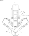
Figure 2 - is the bottom view of the iron when the movement mechanism is in the second position. -
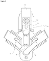
Figure 3 - is the bottom view of the iron when the movement mechanism is in the first position. -
Figure 4 - is the view of the spring and the spring housing on the movement mechanism. -
Figure 5 - is the view of the protrusion and the channel on the movement mechanism. -
Figure 6 - is the view of the claw and the recess on the movement mechanism. - The elements illustrated in the figures are numbered as follows:
- 1. Iron
- 2. Body
- 3. Tank
- 4. Housing
- 5. Locking mechanism
- 6. Actuation member
- 7. Movement member
- 8. Locking arm
- 9. Connection member
- 10. Spring
- 11. Locking member
- 12. Spring housing
- 13. Protrusion
- 14. Channel
- 15. Claw
- 16. Recess
- 17. Protective barrier
- 18. Cavity
- The iron (1) comprises a body (2); a tank (3) which is filled with water so as to generate steam; a housing (4) which is provided on the tank (3) and wherein the body (2) is placed; a cavity (18) which is provided at the rear side of the housing (4) and which is used for locking the rear side of the body (2); and a locking mechanism (5) which is provided on the housing (4) and which enables the body (2) to be locked onto the tank (3). The ironing process is realized by means of the body (2). The body (2) is placed into the housing (4) provided on the tank (3). By means of the cavity (18), the rear side of the body (2) is fixed onto the tank (3). While being carried, the body (2) is fixed onto the tank (3) by means of the locking mechanism (5).
- The iron (1) of the present invention comprises the locking mechanism (5) having an actuation member (6) which is actuated by the user, a movement member (7) with one end connected to the actuation member (6) and the other end extending towards the housing (4), at least two locking arms (8) which enable the soleplate of the body (2) to be fixed, a connection member (9) with one end connected to the movement member (7) and the other end to the locking arm (8), which enables the movement of the movement member (7) to be transferred to the locking arms (8), and at least one spring (10) which is connected to the movement member (7). The actuation member (6) is actuated by the user. By means of the movement of the actuation member (6), the movement member (7) extending into the housing (4) also moves. The movement of the movement member (7) is transferred to the connection member (9). Thus, the locking arms (8) move towards the body (2) so as to provide the locking.
- In an embodiment of the present invention, the iron (1) comprises the locking mechanism (5) having a locking member (11) which is provided on the movement member (7) and which prevents the locking arms (8) from moving without being controlled by the user. By means of the locking member (11), the locking arms (8) cannot be opened without being controlled by the user. Thus, the safety of the user is ensured.
- In an embodiment of the present invention, the iron (1) comprises the locking mechanism (5) having a first position wherein the locking arms (8) engage with the sides of the body (2) and a second position wherein the locking arms (8) release the sides of the body (2). The locking arms (8) hold the body (2) in the first position. Thus, the body (2) is enabled to be fixed onto the tank (3). When the locking mechanism (5) is in the second position, the locking arms (8) are released from the body (2). The body (2) gains the ability to move and the ironing process can be performed.
- In an embodiment of the present invention, the iron (1) comprises the movement member (7) having a spring housing (12) which engages with the spring (10) when the locking mechanism (5) is in the first position. By means of the spring (10) engaging with the spring housing (12), the locking mechanism (5) is prevented from moving between the first position and the second position. Thus, the safety of the user is ensured.
- In an embodiment of the present invention, the iron (1) comprises a protrusion (13) which is provided on the movement member (7), a channel (14) through which the protrusion (13) moves, and the locking mechanism (5) which enables the locking arms (8) to be fixed by means of the protrusion (13) positioned at the two farthest points of the channel (14) from each other when the locking mechanism (5) is in the first position and the second position. While the protrusion (13) moves through the channel (14), the locking mechanism (5) moves between the first position and the second position.
- In an embodiment of the present invention, the iron (1) comprises the channel (14) which is almost quadrilateral. When the protrusion (13) completes a complete tour on the channel (14), the locking mechanism (15) shifts to the first position and the second position.
- In an embodiment of the present invention, the iron (1) comprises a claw (15) which is provided on the movement member (7), a recess (16) which is positioned so as to align with the claw (15), and the locking mechanism (5) which enables the locking arms (8) to be fixed as the claw (15) engages with the recess (6) when the locking mechanism (5) is in the first position. When the locking mechanism (5) is in the first position, the claw (15) engages with the recess (16) and the locking mechanism (5) cannot shift between the first position and the second position. Thus, the safety of the user is ensured.
- In an embodiment of the present invention, the iron (1) comprises the tank (3) having a protective barrier (17) which almost completely surrounds the housing (4). By means of the protective barrier (17), when the soleplate of the iron (1) is hot, the user is prevented from contacting the same.
- By means of the present invention, an iron (1) is realized, comprising a locking mechanism (5) which enables the body (2) to be peripherally fixed onto the tank (3). Thus, the user is enabled to easily carry the iron (1), providing user safety.
Claims (8)
- An iron (1) comprising a body (2); a tank (3) which is filled with water so as to generate steam; a housing (4) which is provided on the tank (3) and wherein the body (2) is placed; a cavity (18) which is provided at the rear side of the housing (4) and which is used for locking the rear side of the body (2); and a locking mechanism (5) which is provided on the housing (4) and which enables the body (2) to be locked onto the tank (3), characterized by the locking mechanism (5) having an actuation member (6) which is actuated by the user, a movement member (7) with one end connected to the actuation member (6) and the other end extending towards the housing (4), at least two locking arms (8) which enable the soleplate of the body (2) to be fixed, a connection member (9) with one end connected to the movement member (7) and the other end to the locking arm (8), which enables the movement of the movement member (7) to be transferred to the locking arms (8), and at least one spring (10) which is connected to the movement member (7).
- An iron (1) as in Claim 1, characterized by the locking mechanism (5) having a locking member (11) which is provided on the movement member (7) and which prevents the locking arms (8) from moving without being controlled by the user.
- An iron (1) as in any one of Claim 1 or Claim 2, characterized by the locking mechanism (5) having a first position wherein the locking arms (8) engage with the sides of the body (2) and a second position wherein the locking arms (8) release the sides of the body (2).
- An iron (1) as in Claim 3, characterized by the movement member (7) having a spring housing (12) which engages with the spring (10) when the locking mechanism (5) is in the first position.
- An iron (1) as in any one of Claim 2 and Claim 4, characterized by a protrusion (13) which is provided on the movement member (7), a channel (14) through which the protrusion (13) moves, and the locking mechanism (5) which enables the locking arms (8) to be fixed by means of the protrusion (13) positioned at the two farthest points of the channel (14) from each other when the locking mechanism (5) is in the first position and the second position.
- An iron (1) as in Claim 5, characterized by the channel (14) which is almost quadrilateral.
- An iron (1) as in any one of Claim 1 to Claim 6, characterized by a claw (15) which is provided on the movement member (7), a recess (16) which is positioned so as to align with the claw (15), and the locking mechanism (5) which enables the locking arms (8) to be fixed as the claw (15) engages with the recess (6) when the locking mechanism (5) is in the first position.
- An iron (1) as in any one of the above claims, characterized by the tank (3) having a protective barrier (17) which almost completely surrounds the housing (4).
Applications Claiming Priority (1)
| Application Number | Priority Date | Filing Date | Title |
|---|---|---|---|
| TR2020/09645A TR202009645A2 (en) | 2020-06-22 | 2020-06-22 | AN IRON WITH LOCKING MECHANISM |
Publications (2)
| Publication Number | Publication Date |
|---|---|
| EP3929348A1 true EP3929348A1 (en) | 2021-12-29 |
| EP3929348B1 EP3929348B1 (en) | 2023-06-07 |
Family
ID=75746515
Family Applications (1)
| Application Number | Title | Priority Date | Filing Date |
|---|---|---|---|
| EP21171620.4A Active EP3929348B1 (en) | 2020-06-22 | 2021-04-30 | An iron comprising a locking mechanism |
Country Status (2)
| Country | Link |
|---|---|
| EP (1) | EP3929348B1 (en) |
| TR (1) | TR202009645A2 (en) |
Citations (4)
| Publication number | Priority date | Publication date | Assignee | Title |
|---|---|---|---|---|
| CN103361952A (en) | 2012-03-31 | 2013-10-23 | 宁波新乐生活电器有限公司 | Electric iron |
| EP3002363A1 (en) * | 2014-10-03 | 2016-04-06 | Seb S.A. | Household appliance comprising an iron and a portable base including an area for setting the iron |
| EP3585932A1 (en) * | 2017-02-21 | 2020-01-01 | De' Longhi Appliances S.r.l. Con Unico Socio | Support base |
| CN210712276U (en) * | 2019-08-07 | 2020-06-09 | 宁波爱佳电器有限公司 | Ironing equipment with locking device |
-
2020
- 2020-06-22 TR TR2020/09645A patent/TR202009645A2/en unknown
-
2021
- 2021-04-30 EP EP21171620.4A patent/EP3929348B1/en active Active
Patent Citations (4)
| Publication number | Priority date | Publication date | Assignee | Title |
|---|---|---|---|---|
| CN103361952A (en) | 2012-03-31 | 2013-10-23 | 宁波新乐生活电器有限公司 | Electric iron |
| EP3002363A1 (en) * | 2014-10-03 | 2016-04-06 | Seb S.A. | Household appliance comprising an iron and a portable base including an area for setting the iron |
| EP3585932A1 (en) * | 2017-02-21 | 2020-01-01 | De' Longhi Appliances S.r.l. Con Unico Socio | Support base |
| CN210712276U (en) * | 2019-08-07 | 2020-06-09 | 宁波爱佳电器有限公司 | Ironing equipment with locking device |
Also Published As
| Publication number | Publication date |
|---|---|
| EP3929348B1 (en) | 2023-06-07 |
| TR202009645A2 (en) | 2022-01-21 |
Similar Documents
| Publication | Publication Date | Title |
|---|---|---|
| JP4063675B2 (en) | Steamer system | |
| EP3596264B1 (en) | Domestic appliance for ironing clothes and similars | |
| JP6795745B2 (en) | Clothing steamer | |
| CN1922354B (en) | Ironing appliance comprising an iron and a portable base | |
| US20100199529A1 (en) | Fastening device for system irons | |
| US9624620B2 (en) | Gravity-fed combined iron and steamer | |
| EP3929348B1 (en) | An iron comprising a locking mechanism | |
| DK163599B (en) | MANUAL BRAKE MECHANISM FOR A REPLACEMENT VALVE, ISAIR FOR A MIXTURE BATTERY | |
| US20120102793A1 (en) | Iron with lip for ironing hard to reach areas on a garment | |
| CA1037856A (en) | Steam iron | |
| Bourdieu | Den biografiske illusjon | |
| CN208965285U (en) | There are two types of the vapour irons of steam mode handoff functionality for tool | |
| CN209010808U (en) | A kind of ironing equipment | |
| CN107513854B (en) | Table type electric iron with lock catch fixing device | |
| CN101245553A (en) | steam ironing machine | |
| EP3949877A1 (en) | Actuation structure of blood vessel clip applier | |
| CN211788715U (en) | Lockable trigger device and hand-held device with trigger device | |
| IT9005154A1 (en) | DEGREE FOR THE SELECTIVE RELEASE OF DOGS IN SHOOTING MECHANISMS FOR TWO-BARREL SPEARGUNS | |
| CN209243443U (en) | A kind of electric iron | |
| CN106480698A (en) | Home appliance including the use steam treatment fabric of the control knob for controlling steam diffusion | |
| RU2817939C2 (en) | Ironing device | |
| US2053950A (en) | Pressing machine | |
| IT227070Y1 (en) | APPARATUS FOR HEATING ENVIRONMENTS AND PREPARING USE WATER | |
| NO800655L (en) | CLUTCH DEVICE FOR AN ELECTRIC TOOL. | |
| EP3947805B1 (en) | Ironing apparatus and method of ironing |
Legal Events
| Date | Code | Title | Description |
|---|---|---|---|
| PUAI | Public reference made under article 153(3) epc to a published international application that has entered the european phase |
Free format text: ORIGINAL CODE: 0009012 |
|
| STAA | Information on the status of an ep patent application or granted ep patent |
Free format text: STATUS: REQUEST FOR EXAMINATION WAS MADE |
|
| 17P | Request for examination filed |
Effective date: 20210430 |
|
| AK | Designated contracting states |
Kind code of ref document: A1 Designated state(s): AL AT BE BG CH CY CZ DE DK EE ES FI FR GB GR HR HU IE IS IT LI LT LU LV MC MK MT NL NO PL PT RO RS SE SI SK SM TR |
|
| B565 | Issuance of search results under rule 164(2) epc |
Effective date: 20211012 |
|
| GRAP | Despatch of communication of intention to grant a patent |
Free format text: ORIGINAL CODE: EPIDOSNIGR1 |
|
| STAA | Information on the status of an ep patent application or granted ep patent |
Free format text: STATUS: GRANT OF PATENT IS INTENDED |
|
| RIC1 | Information provided on ipc code assigned before grant |
Ipc: D06F 75/12 20060101ALN20230201BHEP Ipc: D06F 75/40 20060101AFI20230201BHEP |
|
| RIC1 | Information provided on ipc code assigned before grant |
Ipc: D06F 75/12 20060101ALN20230208BHEP Ipc: D06F 75/40 20060101AFI20230208BHEP |
|
| INTG | Intention to grant announced |
Effective date: 20230222 |
|
| GRAS | Grant fee paid |
Free format text: ORIGINAL CODE: EPIDOSNIGR3 |
|
| GRAA | (expected) grant |
Free format text: ORIGINAL CODE: 0009210 |
|
| STAA | Information on the status of an ep patent application or granted ep patent |
Free format text: STATUS: THE PATENT HAS BEEN GRANTED |
|
| AK | Designated contracting states |
Kind code of ref document: B1 Designated state(s): AL AT BE BG CH CY CZ DE DK EE ES FI FR GB GR HR HU IE IS IT LI LT LU LV MC MK MT NL NO PL PT RO RS SE SI SK SM TR |
|
| REG | Reference to a national code |
Ref country code: GB Ref legal event code: FG4D |
|
| REG | Reference to a national code |
Ref country code: CH Ref legal event code: EP Ref country code: AT Ref legal event code: REF Ref document number: 1575310 Country of ref document: AT Kind code of ref document: T Effective date: 20230615 Ref country code: DE Ref legal event code: R096 Ref document number: 602021002681 Country of ref document: DE |
|
| REG | Reference to a national code |
Ref country code: LT Ref legal event code: MG9D |
|
| REG | Reference to a national code |
Ref country code: NL Ref legal event code: MP Effective date: 20230607 |
|
| PG25 | Lapsed in a contracting state [announced via postgrant information from national office to epo] |
Ref country code: SE Free format text: LAPSE BECAUSE OF FAILURE TO SUBMIT A TRANSLATION OF THE DESCRIPTION OR TO PAY THE FEE WITHIN THE PRESCRIBED TIME-LIMIT Effective date: 20230607 Ref country code: NO Free format text: LAPSE BECAUSE OF FAILURE TO SUBMIT A TRANSLATION OF THE DESCRIPTION OR TO PAY THE FEE WITHIN THE PRESCRIBED TIME-LIMIT Effective date: 20230907 Ref country code: ES Free format text: LAPSE BECAUSE OF FAILURE TO SUBMIT A TRANSLATION OF THE DESCRIPTION OR TO PAY THE FEE WITHIN THE PRESCRIBED TIME-LIMIT Effective date: 20230607 |
|
| REG | Reference to a national code |
Ref country code: AT Ref legal event code: MK05 Ref document number: 1575310 Country of ref document: AT Kind code of ref document: T Effective date: 20230607 |
|
| PG25 | Lapsed in a contracting state [announced via postgrant information from national office to epo] |
Ref country code: RS Free format text: LAPSE BECAUSE OF FAILURE TO SUBMIT A TRANSLATION OF THE DESCRIPTION OR TO PAY THE FEE WITHIN THE PRESCRIBED TIME-LIMIT Effective date: 20230607 Ref country code: NL Free format text: LAPSE BECAUSE OF FAILURE TO SUBMIT A TRANSLATION OF THE DESCRIPTION OR TO PAY THE FEE WITHIN THE PRESCRIBED TIME-LIMIT Effective date: 20230607 Ref country code: LV Free format text: LAPSE BECAUSE OF FAILURE TO SUBMIT A TRANSLATION OF THE DESCRIPTION OR TO PAY THE FEE WITHIN THE PRESCRIBED TIME-LIMIT Effective date: 20230607 Ref country code: LT Free format text: LAPSE BECAUSE OF FAILURE TO SUBMIT A TRANSLATION OF THE DESCRIPTION OR TO PAY THE FEE WITHIN THE PRESCRIBED TIME-LIMIT Effective date: 20230607 Ref country code: HR Free format text: LAPSE BECAUSE OF FAILURE TO SUBMIT A TRANSLATION OF THE DESCRIPTION OR TO PAY THE FEE WITHIN THE PRESCRIBED TIME-LIMIT Effective date: 20230607 Ref country code: GR Free format text: LAPSE BECAUSE OF FAILURE TO SUBMIT A TRANSLATION OF THE DESCRIPTION OR TO PAY THE FEE WITHIN THE PRESCRIBED TIME-LIMIT Effective date: 20230908 |
|
| PG25 | Lapsed in a contracting state [announced via postgrant information from national office to epo] |
Ref country code: FI Free format text: LAPSE BECAUSE OF FAILURE TO SUBMIT A TRANSLATION OF THE DESCRIPTION OR TO PAY THE FEE WITHIN THE PRESCRIBED TIME-LIMIT Effective date: 20230607 |
|
| PG25 | Lapsed in a contracting state [announced via postgrant information from national office to epo] |
Ref country code: SK Free format text: LAPSE BECAUSE OF FAILURE TO SUBMIT A TRANSLATION OF THE DESCRIPTION OR TO PAY THE FEE WITHIN THE PRESCRIBED TIME-LIMIT Effective date: 20230607 |
|
| PG25 | Lapsed in a contracting state [announced via postgrant information from national office to epo] |
Ref country code: IS Free format text: LAPSE BECAUSE OF FAILURE TO SUBMIT A TRANSLATION OF THE DESCRIPTION OR TO PAY THE FEE WITHIN THE PRESCRIBED TIME-LIMIT Effective date: 20231007 |
|
| PG25 | Lapsed in a contracting state [announced via postgrant information from national office to epo] |
Ref country code: SM Free format text: LAPSE BECAUSE OF FAILURE TO SUBMIT A TRANSLATION OF THE DESCRIPTION OR TO PAY THE FEE WITHIN THE PRESCRIBED TIME-LIMIT Effective date: 20230607 Ref country code: SK Free format text: LAPSE BECAUSE OF FAILURE TO SUBMIT A TRANSLATION OF THE DESCRIPTION OR TO PAY THE FEE WITHIN THE PRESCRIBED TIME-LIMIT Effective date: 20230607 Ref country code: RO Free format text: LAPSE BECAUSE OF FAILURE TO SUBMIT A TRANSLATION OF THE DESCRIPTION OR TO PAY THE FEE WITHIN THE PRESCRIBED TIME-LIMIT Effective date: 20230607 Ref country code: PT Free format text: LAPSE BECAUSE OF FAILURE TO SUBMIT A TRANSLATION OF THE DESCRIPTION OR TO PAY THE FEE WITHIN THE PRESCRIBED TIME-LIMIT Effective date: 20231009 Ref country code: IS Free format text: LAPSE BECAUSE OF FAILURE TO SUBMIT A TRANSLATION OF THE DESCRIPTION OR TO PAY THE FEE WITHIN THE PRESCRIBED TIME-LIMIT Effective date: 20231007 Ref country code: EE Free format text: LAPSE BECAUSE OF FAILURE TO SUBMIT A TRANSLATION OF THE DESCRIPTION OR TO PAY THE FEE WITHIN THE PRESCRIBED TIME-LIMIT Effective date: 20230607 Ref country code: CZ Free format text: LAPSE BECAUSE OF FAILURE TO SUBMIT A TRANSLATION OF THE DESCRIPTION OR TO PAY THE FEE WITHIN THE PRESCRIBED TIME-LIMIT Effective date: 20230607 Ref country code: AT Free format text: LAPSE BECAUSE OF FAILURE TO SUBMIT A TRANSLATION OF THE DESCRIPTION OR TO PAY THE FEE WITHIN THE PRESCRIBED TIME-LIMIT Effective date: 20230607 |
|
| PG25 | Lapsed in a contracting state [announced via postgrant information from national office to epo] |
Ref country code: PL Free format text: LAPSE BECAUSE OF FAILURE TO SUBMIT A TRANSLATION OF THE DESCRIPTION OR TO PAY THE FEE WITHIN THE PRESCRIBED TIME-LIMIT Effective date: 20230607 |
|
| REG | Reference to a national code |
Ref country code: DE Ref legal event code: R097 Ref document number: 602021002681 Country of ref document: DE |
|
| PLBE | No opposition filed within time limit |
Free format text: ORIGINAL CODE: 0009261 |
|
| STAA | Information on the status of an ep patent application or granted ep patent |
Free format text: STATUS: NO OPPOSITION FILED WITHIN TIME LIMIT |
|
| PG25 | Lapsed in a contracting state [announced via postgrant information from national office to epo] |
Ref country code: DK Free format text: LAPSE BECAUSE OF FAILURE TO SUBMIT A TRANSLATION OF THE DESCRIPTION OR TO PAY THE FEE WITHIN THE PRESCRIBED TIME-LIMIT Effective date: 20230607 |
|
| PG25 | Lapsed in a contracting state [announced via postgrant information from national office to epo] |
Ref country code: SI Free format text: LAPSE BECAUSE OF FAILURE TO SUBMIT A TRANSLATION OF THE DESCRIPTION OR TO PAY THE FEE WITHIN THE PRESCRIBED TIME-LIMIT Effective date: 20230607 |
|
| 26N | No opposition filed |
Effective date: 20240308 |
|
| PG25 | Lapsed in a contracting state [announced via postgrant information from national office to epo] |
Ref country code: SI Free format text: LAPSE BECAUSE OF FAILURE TO SUBMIT A TRANSLATION OF THE DESCRIPTION OR TO PAY THE FEE WITHIN THE PRESCRIBED TIME-LIMIT Effective date: 20230607 Ref country code: IT Free format text: LAPSE BECAUSE OF FAILURE TO SUBMIT A TRANSLATION OF THE DESCRIPTION OR TO PAY THE FEE WITHIN THE PRESCRIBED TIME-LIMIT Effective date: 20230607 |
|
| PG25 | Lapsed in a contracting state [announced via postgrant information from national office to epo] |
Ref country code: BG Free format text: LAPSE BECAUSE OF FAILURE TO SUBMIT A TRANSLATION OF THE DESCRIPTION OR TO PAY THE FEE WITHIN THE PRESCRIBED TIME-LIMIT Effective date: 20230607 |
|
| PG25 | Lapsed in a contracting state [announced via postgrant information from national office to epo] |
Ref country code: MC Free format text: LAPSE BECAUSE OF FAILURE TO SUBMIT A TRANSLATION OF THE DESCRIPTION OR TO PAY THE FEE WITHIN THE PRESCRIBED TIME-LIMIT Effective date: 20230607 |
|
| PG25 | Lapsed in a contracting state [announced via postgrant information from national office to epo] |
Ref country code: MC Free format text: LAPSE BECAUSE OF FAILURE TO SUBMIT A TRANSLATION OF THE DESCRIPTION OR TO PAY THE FEE WITHIN THE PRESCRIBED TIME-LIMIT Effective date: 20230607 Ref country code: BG Free format text: LAPSE BECAUSE OF FAILURE TO SUBMIT A TRANSLATION OF THE DESCRIPTION OR TO PAY THE FEE WITHIN THE PRESCRIBED TIME-LIMIT Effective date: 20230607 |
|
| REG | Reference to a national code |
Ref country code: CH Ref legal event code: PL |
|
| PG25 | Lapsed in a contracting state [announced via postgrant information from national office to epo] |
Ref country code: LU Free format text: LAPSE BECAUSE OF NON-PAYMENT OF DUE FEES Effective date: 20240430 |
|
| REG | Reference to a national code |
Ref country code: BE Ref legal event code: MM Effective date: 20240430 |
|
| PG25 | Lapsed in a contracting state [announced via postgrant information from national office to epo] |
Ref country code: LU Free format text: LAPSE BECAUSE OF NON-PAYMENT OF DUE FEES Effective date: 20240430 |
|
| PG25 | Lapsed in a contracting state [announced via postgrant information from national office to epo] |
Ref country code: BE Free format text: LAPSE BECAUSE OF NON-PAYMENT OF DUE FEES Effective date: 20240430 |
|
| PG25 | Lapsed in a contracting state [announced via postgrant information from national office to epo] |
Ref country code: BE Free format text: LAPSE BECAUSE OF NON-PAYMENT OF DUE FEES Effective date: 20240430 Ref country code: CH Free format text: LAPSE BECAUSE OF NON-PAYMENT OF DUE FEES Effective date: 20240430 |
|
| PG25 | Lapsed in a contracting state [announced via postgrant information from national office to epo] |
Ref country code: IE Free format text: LAPSE BECAUSE OF NON-PAYMENT OF DUE FEES Effective date: 20240430 |
|
| PG25 | Lapsed in a contracting state [announced via postgrant information from national office to epo] |
Ref country code: CY Free format text: LAPSE BECAUSE OF FAILURE TO SUBMIT A TRANSLATION OF THE DESCRIPTION OR TO PAY THE FEE WITHIN THE PRESCRIBED TIME-LIMIT; INVALID AB INITIO Effective date: 20210430 |
|
| PG25 | Lapsed in a contracting state [announced via postgrant information from national office to epo] |
Ref country code: HU Free format text: LAPSE BECAUSE OF FAILURE TO SUBMIT A TRANSLATION OF THE DESCRIPTION OR TO PAY THE FEE WITHIN THE PRESCRIBED TIME-LIMIT; INVALID AB INITIO Effective date: 20210430 |
|
| PGFP | Annual fee paid to national office [announced via postgrant information from national office to epo] |
Ref country code: GB Payment date: 20260306 Year of fee payment: 6 |
|
| PGFP | Annual fee paid to national office [announced via postgrant information from national office to epo] |
Ref country code: DE Payment date: 20260422 Year of fee payment: 6 |
|
| PGFP | Annual fee paid to national office [announced via postgrant information from national office to epo] |
Ref country code: TR Payment date: 20260402 Year of fee payment: 6 |
|
| PGFP | Annual fee paid to national office [announced via postgrant information from national office to epo] |
Ref country code: FR Payment date: 20260420 Year of fee payment: 6 |