EP3929193A1 - Arylamine compound having benzoazole ring structure, and organic electroluminescent element - Google Patents
Arylamine compound having benzoazole ring structure, and organic electroluminescent element Download PDFInfo
- Publication number
- EP3929193A1 EP3929193A1 EP20759116.5A EP20759116A EP3929193A1 EP 3929193 A1 EP3929193 A1 EP 3929193A1 EP 20759116 A EP20759116 A EP 20759116A EP 3929193 A1 EP3929193 A1 EP 3929193A1
- Authority
- EP
- European Patent Office
- Prior art keywords
- group
- substituted
- unsubstituted
- carbon atoms
- formula
- Prior art date
- Legal status (The legal status is an assumption and is not a legal conclusion. Google has not performed a legal analysis and makes no representation as to the accuracy of the status listed.)
- Granted
Links
- 0 *(*(*1)C(CC2)C=C[C@@]2*(C2C=CC(c3c(cccc4)c4c(C=CCC4)c4c3)=CC2)C(C=C2)=CCC2C2=*C3C=CC=C*3*2)c2c1cccc2 Chemical compound *(*(*1)C(CC2)C=C[C@@]2*(C2C=CC(c3c(cccc4)c4c(C=CCC4)c4c3)=CC2)C(C=C2)=CCC2C2=*C3C=CC=C*3*2)c2c1cccc2 0.000 description 4
Images


Classifications
-
- H—ELECTRICITY
- H10—SEMICONDUCTOR DEVICES; ELECTRIC SOLID-STATE DEVICES NOT OTHERWISE PROVIDED FOR
- H10K—ORGANIC ELECTRIC SOLID-STATE DEVICES
- H10K85/00—Organic materials used in the body or electrodes of devices covered by this subclass
- H10K85/60—Organic compounds having low molecular weight
- H10K85/631—Amine compounds having at least two aryl rest on at least one amine-nitrogen atom, e.g. triphenylamine
-
- C—CHEMISTRY; METALLURGY
- C09—DYES; PAINTS; POLISHES; NATURAL RESINS; ADHESIVES; COMPOSITIONS NOT OTHERWISE PROVIDED FOR; APPLICATIONS OF MATERIALS NOT OTHERWISE PROVIDED FOR
- C09K—MATERIALS FOR MISCELLANEOUS APPLICATIONS, NOT PROVIDED FOR ELSEWHERE
- C09K11/00—Luminescent materials, e.g. electroluminescent or chemiluminescent
- C09K11/06—Luminescent materials, e.g. electroluminescent or chemiluminescent containing organic luminescent materials
-
- C—CHEMISTRY; METALLURGY
- C07—ORGANIC CHEMISTRY
- C07D—HETEROCYCLIC COMPOUNDS
- C07D209/00—Heterocyclic compounds containing five-membered rings, condensed with other rings, with one nitrogen atom as the only ring hetero atom
- C07D209/56—Ring systems containing three or more rings
- C07D209/80—[b, c]- or [b, d]-condensed
- C07D209/82—Carbazoles; Hydrogenated carbazoles
-
- C—CHEMISTRY; METALLURGY
- C07—ORGANIC CHEMISTRY
- C07D—HETEROCYCLIC COMPOUNDS
- C07D251/00—Heterocyclic compounds containing 1,3,5-triazine rings
- C07D251/02—Heterocyclic compounds containing 1,3,5-triazine rings not condensed with other rings
- C07D251/12—Heterocyclic compounds containing 1,3,5-triazine rings not condensed with other rings having three double bonds between ring members or between ring members and non-ring members
- C07D251/14—Heterocyclic compounds containing 1,3,5-triazine rings not condensed with other rings having three double bonds between ring members or between ring members and non-ring members with hydrogen or carbon atoms directly attached to at least one ring carbon atom
- C07D251/24—Heterocyclic compounds containing 1,3,5-triazine rings not condensed with other rings having three double bonds between ring members or between ring members and non-ring members with hydrogen or carbon atoms directly attached to at least one ring carbon atom to three ring carbon atoms
-
- C—CHEMISTRY; METALLURGY
- C07—ORGANIC CHEMISTRY
- C07D—HETEROCYCLIC COMPOUNDS
- C07D263/00—Heterocyclic compounds containing 1,3-oxazole or hydrogenated 1,3-oxazole rings
- C07D263/52—Heterocyclic compounds containing 1,3-oxazole or hydrogenated 1,3-oxazole rings condensed with carbocyclic rings or ring systems
- C07D263/62—Heterocyclic compounds containing 1,3-oxazole or hydrogenated 1,3-oxazole rings condensed with carbocyclic rings or ring systems having two or more ring systems containing condensed 1,3-oxazole rings
-
- C—CHEMISTRY; METALLURGY
- C07—ORGANIC CHEMISTRY
- C07D—HETEROCYCLIC COMPOUNDS
- C07D277/00—Heterocyclic compounds containing 1,3-thiazole or hydrogenated 1,3-thiazole rings
- C07D277/60—Heterocyclic compounds containing 1,3-thiazole or hydrogenated 1,3-thiazole rings condensed with carbocyclic rings or ring systems
- C07D277/62—Benzothiazoles
- C07D277/64—Benzothiazoles with only hydrocarbon or substituted hydrocarbon radicals attached in position 2
- C07D277/66—Benzothiazoles with only hydrocarbon or substituted hydrocarbon radicals attached in position 2 with aromatic rings or ring systems directly attached in position 2
-
- C—CHEMISTRY; METALLURGY
- C07—ORGANIC CHEMISTRY
- C07D—HETEROCYCLIC COMPOUNDS
- C07D405/00—Heterocyclic compounds containing both one or more hetero rings having oxygen atoms as the only ring hetero atoms, and one or more rings having nitrogen as the only ring hetero atom
- C07D405/14—Heterocyclic compounds containing both one or more hetero rings having oxygen atoms as the only ring hetero atoms, and one or more rings having nitrogen as the only ring hetero atom containing three or more hetero rings
-
- C—CHEMISTRY; METALLURGY
- C07—ORGANIC CHEMISTRY
- C07D—HETEROCYCLIC COMPOUNDS
- C07D413/00—Heterocyclic compounds containing two or more hetero rings, at least one ring having nitrogen and oxygen atoms as the only ring hetero atoms
- C07D413/02—Heterocyclic compounds containing two or more hetero rings, at least one ring having nitrogen and oxygen atoms as the only ring hetero atoms containing two hetero rings
- C07D413/12—Heterocyclic compounds containing two or more hetero rings, at least one ring having nitrogen and oxygen atoms as the only ring hetero atoms containing two hetero rings linked by a chain containing hetero atoms as chain links
-
- C—CHEMISTRY; METALLURGY
- C07—ORGANIC CHEMISTRY
- C07D—HETEROCYCLIC COMPOUNDS
- C07D417/00—Heterocyclic compounds containing two or more hetero rings, at least one ring having nitrogen and sulfur atoms as the only ring hetero atoms, not provided for by group C07D415/00
- C07D417/02—Heterocyclic compounds containing two or more hetero rings, at least one ring having nitrogen and sulfur atoms as the only ring hetero atoms, not provided for by group C07D415/00 containing two hetero rings
- C07D417/12—Heterocyclic compounds containing two or more hetero rings, at least one ring having nitrogen and sulfur atoms as the only ring hetero atoms, not provided for by group C07D415/00 containing two hetero rings linked by a chain containing hetero atoms as chain links
-
- H—ELECTRICITY
- H10—SEMICONDUCTOR DEVICES; ELECTRIC SOLID-STATE DEVICES NOT OTHERWISE PROVIDED FOR
- H10K—ORGANIC ELECTRIC SOLID-STATE DEVICES
- H10K50/00—Organic light-emitting devices
- H10K50/10—OLEDs or polymer light-emitting diodes [PLED]
- H10K50/11—OLEDs or polymer light-emitting diodes [PLED] characterised by the electroluminescent [EL] layers
-
- H—ELECTRICITY
- H10—SEMICONDUCTOR DEVICES; ELECTRIC SOLID-STATE DEVICES NOT OTHERWISE PROVIDED FOR
- H10K—ORGANIC ELECTRIC SOLID-STATE DEVICES
- H10K50/00—Organic light-emitting devices
- H10K50/10—OLEDs or polymer light-emitting diodes [PLED]
- H10K50/14—Carrier transporting layers
- H10K50/15—Hole transporting layers
-
- H—ELECTRICITY
- H10—SEMICONDUCTOR DEVICES; ELECTRIC SOLID-STATE DEVICES NOT OTHERWISE PROVIDED FOR
- H10K—ORGANIC ELECTRIC SOLID-STATE DEVICES
- H10K50/00—Organic light-emitting devices
- H10K50/80—Constructional details
- H10K50/84—Passivation; Containers; Encapsulations
-
- H—ELECTRICITY
- H10—SEMICONDUCTOR DEVICES; ELECTRIC SOLID-STATE DEVICES NOT OTHERWISE PROVIDED FOR
- H10K—ORGANIC ELECTRIC SOLID-STATE DEVICES
- H10K50/00—Organic light-emitting devices
- H10K50/80—Constructional details
- H10K50/84—Passivation; Containers; Encapsulations
- H10K50/844—Encapsulations
-
- H—ELECTRICITY
- H10—SEMICONDUCTOR DEVICES; ELECTRIC SOLID-STATE DEVICES NOT OTHERWISE PROVIDED FOR
- H10K—ORGANIC ELECTRIC SOLID-STATE DEVICES
- H10K50/00—Organic light-emitting devices
- H10K50/80—Constructional details
- H10K50/85—Arrangements for extracting light from the devices
- H10K50/858—Arrangements for extracting light from the devices comprising refractive means, e.g. lenses
-
- H—ELECTRICITY
- H10—SEMICONDUCTOR DEVICES; ELECTRIC SOLID-STATE DEVICES NOT OTHERWISE PROVIDED FOR
- H10K—ORGANIC ELECTRIC SOLID-STATE DEVICES
- H10K85/00—Organic materials used in the body or electrodes of devices covered by this subclass
- H10K85/30—Coordination compounds
- H10K85/341—Transition metal complexes, e.g. Ru(II)polypyridine complexes
- H10K85/342—Transition metal complexes, e.g. Ru(II)polypyridine complexes comprising iridium
-
- H—ELECTRICITY
- H10—SEMICONDUCTOR DEVICES; ELECTRIC SOLID-STATE DEVICES NOT OTHERWISE PROVIDED FOR
- H10K—ORGANIC ELECTRIC SOLID-STATE DEVICES
- H10K85/00—Organic materials used in the body or electrodes of devices covered by this subclass
- H10K85/60—Organic compounds having low molecular weight
- H10K85/631—Amine compounds having at least two aryl rest on at least one amine-nitrogen atom, e.g. triphenylamine
- H10K85/636—Amine compounds having at least two aryl rest on at least one amine-nitrogen atom, e.g. triphenylamine comprising heteroaromatic hydrocarbons as substituents on the nitrogen atom
-
- H—ELECTRICITY
- H10—SEMICONDUCTOR DEVICES; ELECTRIC SOLID-STATE DEVICES NOT OTHERWISE PROVIDED FOR
- H10K—ORGANIC ELECTRIC SOLID-STATE DEVICES
- H10K85/00—Organic materials used in the body or electrodes of devices covered by this subclass
- H10K85/60—Organic compounds having low molecular weight
- H10K85/649—Aromatic compounds comprising a hetero atom
- H10K85/654—Aromatic compounds comprising a hetero atom comprising only nitrogen as heteroatom
-
- H—ELECTRICITY
- H10—SEMICONDUCTOR DEVICES; ELECTRIC SOLID-STATE DEVICES NOT OTHERWISE PROVIDED FOR
- H10K—ORGANIC ELECTRIC SOLID-STATE DEVICES
- H10K85/00—Organic materials used in the body or electrodes of devices covered by this subclass
- H10K85/60—Organic compounds having low molecular weight
- H10K85/649—Aromatic compounds comprising a hetero atom
- H10K85/657—Polycyclic condensed heteroaromatic hydrocarbons
-
- H—ELECTRICITY
- H10—SEMICONDUCTOR DEVICES; ELECTRIC SOLID-STATE DEVICES NOT OTHERWISE PROVIDED FOR
- H10K—ORGANIC ELECTRIC SOLID-STATE DEVICES
- H10K85/00—Organic materials used in the body or electrodes of devices covered by this subclass
- H10K85/60—Organic compounds having low molecular weight
- H10K85/649—Aromatic compounds comprising a hetero atom
- H10K85/657—Polycyclic condensed heteroaromatic hydrocarbons
- H10K85/6572—Polycyclic condensed heteroaromatic hydrocarbons comprising only nitrogen in the heteroaromatic polycondensed ring system, e.g. phenanthroline or carbazole
-
- H—ELECTRICITY
- H10—SEMICONDUCTOR DEVICES; ELECTRIC SOLID-STATE DEVICES NOT OTHERWISE PROVIDED FOR
- H10K—ORGANIC ELECTRIC SOLID-STATE DEVICES
- H10K85/00—Organic materials used in the body or electrodes of devices covered by this subclass
- H10K85/60—Organic compounds having low molecular weight
- H10K85/649—Aromatic compounds comprising a hetero atom
- H10K85/657—Polycyclic condensed heteroaromatic hydrocarbons
- H10K85/6574—Polycyclic condensed heteroaromatic hydrocarbons comprising only oxygen in the heteroaromatic polycondensed ring system, e.g. cumarine dyes
-
- C—CHEMISTRY; METALLURGY
- C09—DYES; PAINTS; POLISHES; NATURAL RESINS; ADHESIVES; COMPOSITIONS NOT OTHERWISE PROVIDED FOR; APPLICATIONS OF MATERIALS NOT OTHERWISE PROVIDED FOR
- C09K—MATERIALS FOR MISCELLANEOUS APPLICATIONS, NOT PROVIDED FOR ELSEWHERE
- C09K2211/00—Chemical nature of organic luminescent or tenebrescent compounds
- C09K2211/18—Metal complexes
- C09K2211/185—Metal complexes of the platinum group, i.e. Os, Ir, Pt, Ru, Rh or Pd
-
- H—ELECTRICITY
- H10—SEMICONDUCTOR DEVICES; ELECTRIC SOLID-STATE DEVICES NOT OTHERWISE PROVIDED FOR
- H10K—ORGANIC ELECTRIC SOLID-STATE DEVICES
- H10K2101/00—Properties of the organic materials covered by group H10K85/00
- H10K2101/10—Triplet emission
-
- H—ELECTRICITY
- H10—SEMICONDUCTOR DEVICES; ELECTRIC SOLID-STATE DEVICES NOT OTHERWISE PROVIDED FOR
- H10K—ORGANIC ELECTRIC SOLID-STATE DEVICES
- H10K2101/00—Properties of the organic materials covered by group H10K85/00
- H10K2101/90—Multiple hosts in the emissive layer
-
- H—ELECTRICITY
- H10—SEMICONDUCTOR DEVICES; ELECTRIC SOLID-STATE DEVICES NOT OTHERWISE PROVIDED FOR
- H10K—ORGANIC ELECTRIC SOLID-STATE DEVICES
- H10K2102/00—Constructional details relating to the organic devices covered by this subclass
- H10K2102/301—Details of OLEDs
- H10K2102/351—Thickness
-
- H—ELECTRICITY
- H10—SEMICONDUCTOR DEVICES; ELECTRIC SOLID-STATE DEVICES NOT OTHERWISE PROVIDED FOR
- H10K—ORGANIC ELECTRIC SOLID-STATE DEVICES
- H10K50/00—Organic light-emitting devices
- H10K50/10—OLEDs or polymer light-emitting diodes [PLED]
- H10K50/14—Carrier transporting layers
- H10K50/15—Hole transporting layers
- H10K50/156—Hole transporting layers comprising a multilayered structure
-
- H—ELECTRICITY
- H10—SEMICONDUCTOR DEVICES; ELECTRIC SOLID-STATE DEVICES NOT OTHERWISE PROVIDED FOR
- H10K—ORGANIC ELECTRIC SOLID-STATE DEVICES
- H10K59/00—Integrated devices, or assemblies of multiple devices, comprising at least one organic light-emitting element covered by group H10K50/00
- H10K59/80—Constructional details
- H10K59/875—Arrangements for extracting light from the devices
- H10K59/879—Arrangements for extracting light from the devices comprising refractive means, e.g. lenses
-
- H—ELECTRICITY
- H10—SEMICONDUCTOR DEVICES; ELECTRIC SOLID-STATE DEVICES NOT OTHERWISE PROVIDED FOR
- H10K—ORGANIC ELECTRIC SOLID-STATE DEVICES
- H10K85/00—Organic materials used in the body or electrodes of devices covered by this subclass
- H10K85/30—Coordination compounds
- H10K85/341—Transition metal complexes, e.g. Ru(II)polypyridine complexes
- H10K85/346—Transition metal complexes, e.g. Ru(II)polypyridine complexes comprising platinum
Definitions
- the present invention relates to a compound suitable for an organic electroluminescence device (abbreviated hereinbelow as "organic EL device”) which is a self-luminous light-emitting device suitable for various display devices, and to the organic EL device. More specifically, the present invention relates to an arylamine compound having a benzazole ring structure, and to an organic EL device employing the compound.
- organic EL device organic electroluminescence device
- Organic EL devices which are self-luminous light-emitting devices, are brighter, have better visibility, and are capable of clearer display compared to liquid crystal devices. Therefore, organic EL devices have been actively researched.
- top-emission light-emitting devices which allow light emission from the top side by using, as an anode, a metal having a high work function.
- a metal having a high work function In the aforementioned bottom-emission structure, light exits from the bottom side where pixel circuits are provided; this configuration unfortunately limits the area from which light can be extracted.
- top-emission light-emitting devices light exits from the top side; this is advantageous in that the area for extracting light can be increased, since the pixel circuits do not get in the way.
- Non-Patent Literature 2 To further improve luminous efficiency, attempts have been made to employ triplet excitons. Also, the use of phosphorescent substances has been investigated (see, for example, Non-Patent Literature 2).
- the light-emitting layer can be prepared by doping a charge-transporting compound, typically called a "host material", with a fluorescent substance or a phosphorescent substance.
- a charge-transporting compound typically called a "host material”
- a fluorescent substance or a phosphorescent substance typically called a fluorescent substance or a phosphorescent substance.
- Iridium complexes are typically used as materials exhibiting high luminous efficiency as phosphorescent substances. Unfortunately, the emission spectra of organic EL devices employing iridium complexes have broad half-widths, thus resulting in poor color purity.
- a light-emitting device configuration As a means for improving color purity as well as luminous efficiency, a light-emitting device configuration has been proposed, wherein a "capping layer" having a high refractive index is provided on the outer side of a semi-transparent electrode having a low refractive index, to thereby constitute an optical resonator called a "microcavity" to adjust the emission spectrum (see, for example, Patent Literature 5).
- Alq3 and arylamine compounds have been proposed as materials for the capping layer (see, for example, Non-Patent Literature 3 and Patent Literature 6).
- these conventional materials have low refractive indices in the green and red emission ranges, thus resulting in poor light extraction efficiency.
- devices provided with a capping layer using such conventional materials allow transmission of sunlight within the wavelength range of 400 nm to 410 nm, which may affect materials inside the device. This may also impair color purity as well as light extraction efficiency.
- An objective of the present invention is to provide an organic EL device that employs, in combination, various materials for an organic EL device that have excellent injection-transport performance of holes and electrons and have excellent stability and durability in a thin-film state, and a capping layer composed from a material that has a high light absorption coefficient to absorb sunlight within the wavelength range of 400 nm to 410 nm and thereby prevent impact on materials inside the organic EL device, has a high refractive index to significantly improve light extraction efficiency, has excellent stability, durability and light resistance in a thin film, and has no absorption within the wavelength ranges of blue, green and red, to thereby effectively achieve the characteristics of the respective materials in order to provide an organic EL device having (1) high luminous efficiency and high power efficiency, (2) a low emission start voltage, (3) a low practical driving voltage, and (4) a particularly long lifetime.
- Physical characteristics of a capping layer material suitable for achieving the aforementioned objective may include, for example, (1) capability of absorbing light within the range from 400 nm to 410 nm, (2) a high refractive index, (3) capability of vapor deposition without thermal decomposition, (4) stability in a thin-film state, and (5) a high glass transition temperature.
- Physical characteristics of a device suitable for the present invention may include, for example, (1) high light extraction efficiency, (2) no deterioration of color purity, (3) transmission of light with no change over time, (4) high luminous efficiency and power efficiency, (5) a low emission start voltage, (6) a low practical driving voltage, and (7) a particularly long lifetime.
- arylamine materials have excellent stability and durability in a thin film, and that metal complexes, as phosphorescent dopants, have excellent luminous efficiency.
- Inventors produced various organic EL devices by selecting and using, as capping layer materials, specific benzazole-ring-structure arylamine compounds that have a high refractive index within the wavelength range of 400 nm to 650 nm and have a high extinction coefficient within the wavelength range of 400 nm to 410 nm, and by combining those compounds with phosphorescent dopant-containing light-emitting layers. Further, Inventors diligently assessed the characteristics of those devices, to thus accomplish the present invention.
- An organic EL device of the present disclosure capable of solving the aforementioned problems includes at least an anode, a first hole transport layer, a second hole transport layer, a light-emitting layer, an electron transport layer, a cathode, and a capping layer in this order, wherein: the capping layer contains an arylamine compound having a group (benzazole ring structure) represented by the following formula (1); and the light-emitting layer contains a host and a phosphorescent dopant which is a metal complex containing iridium or platinum.
- R 1 to R 4 each independently represent a hydrogen atom, a deuterium atom, a fluorine atom, a chlorine atom, a cyano group, a nitro group, a silyl group, a linear or branched alkyl group having 1 to 6 carbon atoms and optionally having a substituent, a cycloalkyl group having 5 to 10 carbon atoms and optionally having a substituent, a linear or branched alkenyl group having 2 to 6 carbon atoms and optionally having a substituent, a linear or branched alkyloxy group having 1 to 6 carbon atoms and optionally having a substituent, a cycloalkyloxy group having 5 to 10 carbon atoms and optionally having a substituent, a substituted or unsubstituted aromatic hydrocarbon group, a substituted or unsubstituted aromatic heterocyclic group, a substituted or unsubstituted fused polycyclic aromatic group, or a
- the organic EL device of the present invention includes a capping layer provided on the outer side of a transparent or semi-transparent electrode and having a higher refractive index than the electrode, and is thus significantly improved in color purity and light extraction efficiency. Further, by using, for the capping layer, an arylamine compound having a group represented by formula (1), sunlight within the range of 400 to 410 nm can be absorbed, and thus, damage to the light-emitting device can be prevented. With these characteristics, the organic EL device can be suitably applied to full-color displays and can display images with high definition.
- R 1 to R 4 each independently represent a hydrogen atom, a deuterium atom, a fluorine atom, a chlorine atom, a cyano group, a nitro group, a silyl group, a linear or branched alkyl group having 1 to 6 carbon atoms and optionally having a substituent, a cycloalkyl group having 5 to 10 carbon atoms and optionally having a substituent, a linear or branched alkenyl group having 2 to 6 carbon atoms and optionally having a substituent, a linear or branched alkyloxy group having 1 to 6 carbon atoms and optionally having a substituent, a cycloalkyloxy group having 5 to 10 carbon atoms and optionally having a substituent, a substituted or unsubstituted aromatic hydrocarbon group, a substituted or unsubstituted aromatic heterocyclic group, a substituted or unsubstituted fused polycyclic aromatic group, or a
- Ar 2 , Ar 3 , and Ar 4 each independently represent a substituted or unsubstituted aromatic hydrocarbon group, a substituted or unsubstituted aromatic heterocyclic group, a substituted or unsubstituted fused polycyclic aromatic group, or a group represented by the formula (1), wherein at least one of Ar 2 , Ar 3 , and Ar 4 is a group represented by the formula (1).
- Ar 5 , Ar 6 , Ar 7 , and Ar 8 each independently represent a substituted or unsubstituted aromatic hydrocarbon group, a substituted or unsubstituted aromatic heterocyclic group, a substituted or unsubstituted fused polycyclic aromatic group, or a group represented by the formula (1), wherein at least one of Ar 5 , Ar 6 , Ar 7 , and Ar 8 is a group represented by the formula (1); and L 1 represents a substituted or unsubstituted phenylene group, a substituted or unsubstituted biphenylene group, or a substituted or unsubstituted terphenylene group.
- the plural Z each independently represent N or CRa, wherein at least one of the plural Z is N;
- Y 1 and Y 2 each independently represent a single bond, a substituted or unsubstituted aryl group having 6 to 30 carbon atoms, or a substituted or unsubstituted heteroaryl group having 5 to 30 carbon atoms;
- R 17 to R 32 each independently represent a hydrogen atom, a deuterium atom, a fluorine atom, a chlorine atom, a linear or branched alkyl group having 1 to 6 carbon atoms and optionally having a substituent, a cycloalkyl group having 5 to 10 carbon atoms and optionally having a substituent, a linear or branched alkenyl group having 2 to 6 carbon atoms and optionally having a substituent, a linear or branched alkyloxy group having 1 to 6 carbon atoms and optionally having a substituent, a cycloalkyloxy group having 5 to 10 carbon atoms and optionally having a substituent, a trimethylsilyl group, a substituted or unsubstituted aromatic hydrocarbon group, a substituted or unsubstituted aromatic heterocyclic group, a substituted or unsubstituted fused polycyclic aromatic group, a substituted or unsubstituted aryl
- R 36 to R 39 , Rb, and Rc each independently represent a hydrogen atom, a deuterium atom, a fluorine atom, a chlorine atom, a cyano group, a nitro group, a substituted or unsubstituted alkyl group having 1 to 15 carbon atoms, or a substituted or unsubstituted aryl group having 6 to 12 carbon atoms.
- aromatic hydrocarbon group "aromatic heterocyclic group” or “fused polycyclic aromatic group” in the "substituted or unsubstituted aromatic hydrocarbon group", “substituted or unsubstituted aromatic heterocyclic group” or “substituted or unsubstituted fused polycyclic aromatic group” as represented by Ar 1 to Ar 8 in the aforementioned formulas (1), (2), and (3) may include a phenyl group, a biphenylyl group, a terphenylyl group, a naphthyl group, an anthracenyl group, a phenanthrenyl group, a fluorenyl group, an indenyl group, a pyrenyl group, a perylenyl group, a fluoranthenyl group, a triphenylenyl group, a pyridyl group, a pyrimidinyl group, a triazinyl group,
- substituted aromatic hydrocarbon group may include: a deuterium atom; a cyano group; a nitro group; halogen atoms, such as a fluorine atom, a chlorine atom, a bromine atom, or an iodine atom; linear or branched alkyl groups having 1 to 6 carbon atoms, such as a methyl group, an ethyl group, a n-propyl group, an isopropyl group, a n-butyl group, an isobutyl group, a tert-butyl group, a n-pentyl group, an isopentyl group, a neopentyl group, a n-hexy
- substituents may further be substituted by any of the substituents given as examples above. Further, these substituents may be bonded to each other via a single bond, a substituted or unsubstituted methylene group, an oxygen atom, or a sulfur atom, to form a ring.
- substituents may further be substituted by any of the substituents given as examples above. Further, these substituents may be bonded to each other via a single bond, a substituted or unsubstituted methylene group, an oxygen atom, or a sulfur atom, to form a ring.
- Examples of the "substituent" in the "linear or branched alkyloxy group having 1 to 6 carbon atoms and having a substituent” or “cycloalkyloxy group having 5 to 10 carbon atoms and having a substituent” as represented by R 1 to R 4 in the aforementioned formula (1) may include the aforementioned examples given for the "substituent” in the "linear or branched alkyl group having 1 to 6 carbon atoms and having a substituent", "cycloalkyl group having 5 to 10 carbon atoms and having a substituent” or “linear or branched alkenyl group having 2 to 6 carbon atoms and having a substituent” as represented by R 1 to R 4 in the aforementioned general formula (1), and they may take similar forms/configurations as those described above.
- Examples of the "aromatic hydrocarbon group", “aromatic heterocyclic group” or “fused polycyclic aromatic group” in the “substituted or unsubstituted aromatic hydrocarbon group", “substituted or unsubstituted aromatic heterocyclic group” or “substituted or unsubstituted fused polycyclic aromatic group” as represented by R 1 to R 4 in the aforementioned formula (1) may include the aforementioned examples given for the "aromatic hydrocarbon group”, “aromatic heterocyclic group” or “fused polycyclic aromatic group” in the "substituted or unsubstituted aromatic hydrocarbon group", “substituted or unsubstituted aromatic heterocyclic group” or “substituted or unsubstituted fused polycyclic aromatic group” as represented by Ar 1 to Ar 8 in the aforementioned formulas (1), (2), and (3).
- These groups may be bonded to each other via a single bond, a substituted or unsubstituted methylene group, an oxygen atom, or a sulfur atom, to form a ring. Further, these groups may have a substituent, and examples of the substituent may include the aforementioned examples given for the "substituent" in the "substituted aromatic hydrocarbon group", "substituted aromatic heterocyclic group” or "substituted fused polycyclic aromatic group” as represented by Ar 1 to Ar 8 in the aforementioned formulas (1), (2), and (3), and they may take similar forms/configurations as those described above.
- aryloxy group in the "substituted or unsubstituted aryloxy group” as represented by R 1 to R 4 in the aforementioned formula (1) may include a phenyloxy group, a biphenylyloxy group, a terphenylyloxy group, a naphthyloxy group, an anthracenyloxy group, a phenanthrenyloxy group, a fluorenyloxy group, an indenyloxy group, a pyrenyloxy group, a perylenyloxy group, etc.
- These groups may be bonded to each other via a single bond, a substituted or unsubstituted methylene group, an oxygen atom, or a sulfur atom, to form a ring. Further, these groups may have a substituent, and examples of the substituent may include the aforementioned examples given for the "substituent" in the "substituted aromatic hydrocarbon group", "substituted aromatic heterocyclic group” or "substituted fused polycyclic aromatic group” as represented by Ar 1 to Ar 8 in the aforementioned formulas (1), (2), and (3), and they may take similar forms/configurations as those described above.
- R 1 to R 4 and Ar 1 in the aforementioned formula (1) is a linking group as a bonding site.
- one of R 1 to R 4 and Ar 1 in the aforementioned formula (1) is a linking group for bonding the group represented by the formula (1) and another structure in the arylamine compound having the group represented by the formula (1).
- R 1 to R 4 may be a single bond.
- Ar 1 in the formula (1) is a "substituted or unsubstituted aromatic hydrocarbon group" or "substituted or unsubstituted fused polycyclic aromatic group", more preferably a phenyl group or a biphenyl group, and further preferably a phenyl group.
- R 1 to R 4 in the formula (1) are preferably a hydrogen atom or a deuterium atom, and from the viewpoint of synthesis, are more preferably a hydrogen atom.
- the arylamine compound having a group represented by the formula (1) is an arylamine compound represented by the aforementioned formula (2) or (3). It is also preferable that Ar 1 in the formula (1) is bonded to the nitrogen atom in the formula (2) or (3).
- At least one of Ar 2 to Ar 4 in the formula (2) is a group represented by the formula (1), and it is preferable that two of Ar 2 to Ar 4 each independently represent a group represented by the formula (1).
- at least one of Ar 5 to Ar 8 in the formula (3) is a group represented by the formula (1), and it is preferable that two of Ar 5 to Ar 8 each independently represent a group represented by the formula (1), and it is even preferable that Ar 5 and Ar 8 each independently represent a group represented by the formula (1).
- groups other than the group(s) represented by the formula (1) are preferably a "substituted or unsubstituted aromatic hydrocarbon group" or "substituted or unsubstituted fused polycyclic aromatic group", and more preferably a substituted or unsubstituted phenyl group or a substituted or unsubstituted biphenyl group.
- substituents of the phenyl group and biphenyl group may preferably include a phenyl group, a naphthyl group, and a phenanthrenyl group. Concrete examples of preferred groups may include groups represented by the following formulas.
- L 1 in the aforementioned formula (3) is preferably a substituted or unsubstituted biphenylene group, or a substituted or unsubstituted terphenylene group, and from the viewpoint of synthesis, is more preferably an unsubstituted biphenylene group or an unsubstituted terphenylene group.
- Figs. 1 to 11 illustrate concrete examples of preferred compounds among arylamine compounds represented by the formula (1) that may be suitably used for the organic EL device of the present invention. Note, however, that the compounds are not limited to the illustrated compounds.
- alkyl group having 1 to 15 carbon atoms in the "substituted or unsubstituted alkyl group having 1 to 15 carbon atoms” as represented by R 5 to R 10 and Ra in the formula (Host-A) may include a methyl group, an ethyl group, a propyl group, an isopropyl group, a n-butyl group, a s-butyl group, an isobutyl group, a t-butyl group, a n-pentyl group, a n-hexyl group, a n-heptyl group, a n-octyl group, a hydroxymethyl group, a 1-hydroxyethyl group, a 2-hydroxyethyl group, a 2-hydroxyisobutyl group, a 1,2-dihydroxyethyl group, a 1,3-dihydroxyisopropyl group, a 2,3-dihydroxy-t
- Examples of the "substituent" in the "substituted or unsubstituted alkyl group having 1 to 15 carbon atoms" as represented by R 5 to R 10 and Ra in the formula (Host-A) may include the aforementioned examples given for the "substituent” in the "linear or branched alkyl group having 1 to 6 carbon atoms and having a substituent", "cycloalkyl group having 5 to 10 carbon atoms and having a substituent” or “linear or branched alkenyl group having 2 to 6 carbon atoms and having a substituent” as represented by R 1 to R 4 in the aforementioned formula (1), and they may take similar forms/configurations as those described above.
- Concrete examples of the "substituted or unsubstituted aryl group having 6 to 15 carbon atoms" as represented by R 5 to R 10 and Ra in the formula (Host-A) may include a phenyl group, a biphenylyl group, a 9,9'-dimethylfluorenyl group, a 1-naphthyl group, a 2-naphthyl group, a fluorophenyl group, a difluorophenyl group, a trifluorophenyl group, a tetrafluorophenyl group, a pentafluorophenyl group, a toluyl group, a nitrophenyl group, a cyanophenyl group, a fluorobiphenylyl group, a nitrobiphenylyl group, a cyanobiphenyl group, a cyanonaphthyl group, a nitronaphthyl group,
- Examples of the "substituent" in the "substituted or unsubstituted aryl group having 6 to 12 ring-forming carbon atoms" as represented by R 5 to R 10 and Ra in the formula (Host-A) may include the aforementioned examples given for the "substituent” in the "substituted aromatic hydrocarbon group", "substituted aromatic heterocyclic group” or "substituted fused polycyclic aromatic group” as represented by Ar 1 to Ar 8 in the aforementioned formulas (1), (2), and (3), and they may take similar forms/configurations as those described above.
- Examples of the "substituent" in the "substituted or unsubstituted arylene group having 6 to 30 ring-forming carbon atoms” or “substituted or unsubstituted heteroarylene group having 5 to 30 ring-forming carbon atoms” as represented by L 1 and L 2 in the formula (Host-A) may include the aforementioned examples given for the "substituent” in the "substituted aromatic hydrocarbon group", “substituted aromatic heterocyclic group” or “substituted fused polycyclic aromatic group” as represented by Ar 1 to Ar 8 in the aforementioned formulas (1), (2), and (3), and they may take similar forms/configurations as those described above.
- Figs. 12 to 16 illustrate concrete examples of preferred compounds among first host compounds represented by the formula (Host-A) that may be suitably used for the organic EL device of the present invention. Note, however, that the compounds are not limited to the illustrated compounds.
- compound (A-43) illustrated in Fig. 14 is preferable, although the compound does not constitute a limitation.
- Examples of the "substituent" in the "substituted or unsubstituted aryl group having 6 to 30 carbon atoms” or “substituted or unsubstituted heteroaryl group having 5 to 30 carbon atoms” as represented by Ar 9 and Ar 10 in the formula (Host-B) may include the aforementioned examples given for the "substituent” in the "substituted aromatic hydrocarbon group", “substituted aromatic heterocyclic group” or “substituted fused polycyclic aromatic group” as represented by Ar 1 to Ar 8 in the aforementioned formulas (1), (2), and (3), and they may take similar forms/configurations as those described above.
- alkyl group having 1 to 15 carbon atoms may include a methyl group, an ethyl group, a propyl group, an isopropyl group, a n-butyl group, a s-butyl group, an isobutyl group, a t-butyl group, a n-pentyl group, a n-hexyl group, a n-heptyl group, a n-octyl group, a hydroxymethyl group, a 1-hydroxyethyl group, a 2-hydroxyethyl group, a 2-hydroxyisobutyl group, a 1,2-dihydroxyethyl group, a 1,3-dihydroxyisopropyl group, a 2,3-dihydroxy-t-butyl group, a 1,2,3-trihydroxypropyl group, a chloromethyl group, a 1-ch
- Examples of the "substituent" in the "alkyl group having 1 to 15 carbon atoms” as represented by R 11 to R 16 in the formula (Host-B) may include the aforementioned examples given for the "substituent” in the "linear or branched alkyl group having 1 to 6 carbon atoms and having a substituent", "cycloalkyl group having 5 to 10 carbon atoms and having a substituent” or "linear or branched alkenyl group having 2 to 6 carbon atoms and having a substituent” as represented by R 1 to R 4 in the aforementioned formula (1), and they may take similar forms/configurations as those described above.
- Examples of the "substituted or unsubstituted aryl group having 6 to 30 ring-forming carbon atoms" or “substituted or unsubstituted heteroaryl group having 5 to 30 ring-forming carbon atoms" as represented by R 11 to R 16 in the formula (Host-B) may include a phenyl group, a biphenylyl group, a terphenylyl group, a naphthyl group, an anthracenyl group, a phenanthrenyl group, a fluorenyl group, an indenyl group, a pyrenyl group, a perylenyl group, a fluoranthenyl group, a triphenylenyl group, a pyridyl group, a pyrimidinyl group, a triazinyl group, a furyl group, a pyrrolyl group, a thienyl group, a quinolyl group,
- Examples of the "substituent" in the "substituted or unsubstituted aryl group having 6 to 30 ring-forming carbon atoms” or “substituted or unsubstituted heteroaryl group having 5 to 30 ring-forming carbon atoms” as represented by R 11 to R 16 in the formula (Host-B) may include the aforementioned examples given for the "substituent” in the "substituted aromatic hydrocarbon group", “substituted aromatic heterocyclic group” or “substituted fused polycyclic aromatic group” as represented by Ar 1 to Ar 8 in the aforementioned formulas (1), (2), and (3), and they may take similar forms/configurations as those described above.
- Examples of the "substituent" in the "substituted or unsubstituted aryl group having 6 to 30 carbon atoms” or “substituted or unsubstituted heteroaryl group having 5 to 30 carbon atoms” as represented by Y 1 and Y 2 in the formula (Host-B) may include the aforementioned examples given for the "substituent” in the "substituted aromatic hydrocarbon group", “substituted aromatic heterocyclic group” or “substituted fused polycyclic aromatic group” as represented by Ar 1 to Ar 8 in the aforementioned formulas (1), (2), and (3), and they may take similar forms/configurations as those described above.
- Figs. 17 to 20 illustrate concrete examples of preferred compounds among second host compounds represented by the formula (Host-B) that may be suitably used for the organic EL device of the present invention. Note, however, that the compounds are not limited to the illustrated compounds.
- compound (B-25) illustrated in Fig. 18 is preferable, although the compound does not constitute a limitation.
- Examples of the "substituent" in the "linear or branched alkyl group having 1 to 6 carbon atoms and optionally having a substituent", "cycloalkyl group having 5 to 10 carbon atoms and optionally having a substituent” or “linear or branched alkenyl group having 2 to 6 carbon atoms and optionally having a substituent” as represented by R 17 to R 32 in the formula (4) may include the aforementioned examples given for the "substituent” in the "linear or branched alkyl group having 1 to 6 carbon atoms and having a substituent", “cycloalkyl group having 5 to 10 carbon atoms and having a substituent” or “linear or branched alkenyl group having 2 to 6 carbon atoms and having a substituent” as represented by R 1 to R 4 in the aforementioned formula (1), and they may take similar forms/configurations as those described above.
- Examples of the "substituent" in the "linear or branched alkyloxy group having 1 to 6 carbon atoms and having a substituent” or “cycloalkyloxy group having 5 to 10 carbon atoms and having a substituent” as represented by R 17 to R 32 in the formula (4) may include the aforementioned examples given for the "substituent” in the "linear or branched alkyl group having 1 to 6 carbon atoms and having a substituent", "cycloalkyl group having 5 to 10 carbon atoms and having a substituent” or “linear or branched alkenyl group having 2 to 6 carbon atoms and having a substituent” as represented by R 1 to R 4 in the aforementioned formula (1), and they may take similar forms/configurations as those described above.
- aryloxy group in the "substituted or unsubstituted aryloxy group” as represented by R 17 to R 32 in the formula (4) may include a phenyloxy group, a biphenylyloxy group, a terphenylyloxy group, a naphthyloxy group, an anthracenyloxy group, a phenanthrenyloxy group, a fluorenyloxy group, an indenyloxy group, a pyrenyloxy group, a perylenyloxy group, etc. These groups may be bonded to each other via a single bond, a substituted or unsubstituted methylene group, an oxygen atom, or a sulfur atom, to form a ring.
- Examples of the "substituent" in the "substituted or unsubstituted aryloxy group" as represented by R 17 to R 32 in the formula (4) may include the aforementioned examples given for the "substituent” in the "substituted or unsubstituted aryloxy group” as represented by R 1 to R 4 in the aforementioned formula (1), and they may take similar forms/configurations as those described above.
- aromatic hydrocarbon group "aromatic heterocyclic group” or “fused polycyclic aromatic group” in the "substituted or unsubstituted aromatic hydrocarbon group", “substituted or unsubstituted aromatic heterocyclic group” or “substituted or unsubstituted fused polycyclic aromatic group” as represented by R 17 to R 32 in the formula (4) may include a phenyl group, a naphthyl group, an anthracenyl group, a phenanthryl group, a naphthacenyl group, a pyrenyl group, a biphenylyl group, a p-terphenyl group, a m-terphenyl group, a chrysenyl group, a triphenylenyl group, a perylenyl group, an indenyl group, a furanyl group, a thiophenyl group, a pyrrolyl
- Examples of the "substituent" in the "substituted or unsubstituted aromatic hydrocarbon group", "substituted or unsubstituted aromatic heterocyclic group", or “substituted or unsubstituted fused polycyclic aromatic group” as represented by R 17 to R 32 in the formula (4) may include the aforementioned examples given for the "substituent” in the "substituted aromatic hydrocarbon group", “substituted aromatic heterocyclic group” or “substituted fused polycyclic aromatic group” as represented by Ar 1 to Ar 8 in the aforementioned formulas (1), (2), and (3), and they may take similar forms/configurations as those described above.
- Figs. 21 to 23 illustrate concrete examples of preferred compounds among metal complexes represented by the formula (4) that may be suitably used for the organic EL device of the present invention. Note, however, that the compounds are not limited to the illustrated compounds.
- compound (4-35) illustrated in Fig. 23 is preferable, although the compound does not constitute a limitation.
- Examples of the "substituent" in the "substituted or unsubstituted aryl group having 6 to 30 carbon atoms” or “substituted or unsubstituted heteroaryl group having 5 to 30 carbon atoms” as represented by Ar 11 and Ar 12 in the formula (5) may include the aforementioned examples given for the "substituent” in the "substituted aromatic hydrocarbon group", “substituted aromatic heterocyclic group” or “substituted fused polycyclic aromatic group” as represented by Ar 1 to Ar 8 in the aforementioned formulas (1), (2), and (3), and they may take similar forms/configurations as those described above.
- alkyl group having 1 to 15 carbon atoms in the "substituted or unsubstituted alkyl group having 1 to 15 carbon atoms” as represented by R 33 to R 39 in the formulas (5) and (6) may include a methyl group, an ethyl group, a propyl group, an isopropyl group, a n-butyl group, a s-butyl group, an isobutyl group, a t-butyl group, a n-pentyl group, a n-hexyl group, a n-heptyl group, a n-octyl group, a hydroxymethyl group, a 1-hydroxyethyl group, a 2-hydroxyethyl group, a 2-hydroxyisobutyl group, a 1,2-dihydroxyethyl group, a 1,3-dihydroxyisopropyl group, a 2,3-dihydroxy-t-but
- Examples of the "substituent" in the "substituted or unsubstituted alkyl group having 1 to 15 carbon atoms" as represented by R 33 to R 39 in the formulas (5) and (6) may include the aforementioned examples given for the "substituent” in the "linear or branched alkyl group having 1 to 6 carbon atoms and having a substituent", "cycloalkyl group having 5 to 10 carbon atoms and having a substituent” or “linear or branched alkenyl group having 2 to 6 carbon atoms and having a substituent” as represented by R 1 to R 4 in the aforementioned formula (1), and they may take similar forms/configurations as those described above.
- aryl group having 6 to 12 carbon atoms in the "substituted or unsubstituted aryl group having 6 to 12 carbon atoms” as represented by R 33 to R 39 in the formulas (5) and (6) may include a phenyl group, a biphenylyl group, a 1-naphthyl group, a 2-naphthyl group, a fluorophenyl group, a difluorophenyl group, a trifluorophenyl group, a tetrafluorophenyl group, a pentafluorophenyl group, a toluyl group, a nitrophenyl group, a cyanophenyl group, a fluorobiphenylyl group, a nitrobiphenylyl group, a cyanobiphenyl group, a cyanonaphthyl group, a nitronaphthyl group, a fluor
- Examples of the "substituent" in the "substituted or unsubstituted aryl group having 6 to 12 carbon atoms" as represented by R 33 to R 39 in the formulas (5) and (6) may include the aforementioned examples given for the "substituent” in the "substituted aromatic hydrocarbon group", "substituted aromatic heterocyclic group” or "substituted fused polycyclic aromatic group” as represented by Ar 1 to Ar 8 in the aforementioned formulas (1), (2), and (3), and they may take similar forms/configurations as those described above.
- Ar 11 and Ar 12 in the formula (5) are an unsubstituted biphenyl group, an unsubstituted terphenyl group, an unsubstituted triphenylenyl group, an unsubstituted phenanthrenyl group, a fluorenyl group having a substituent, or a thienyl group having a substituent, and more preferably an unsubstituted biphenyl group or a fluorenyl group having a substituent. It is preferable that the substituent of the fluorenyl group and thienyl group is a methyl group or a phenyl group, and it is even preferable that the substituent of the fluorenyl group is a methyl group.
- R 33 to R 37 in the formulas (5) and (6) are a hydrogen atom or a deuterium atom, and from the viewpoint of synthesis, is more preferably a hydrogen atom. It is preferable that R 38 and R 39 in the formula (6) is a methyl group.
- Figs. 24 to 27 illustrate concrete examples of preferred compounds among arylamine compounds represented by the formula (5) that may be suitably used for the organic EL device of the present invention. Note, however, that the compounds are not limited to the illustrated compounds.
- compound (5-48) illustrated in Fig. 26 is preferable, although the compound does not constitute a limitation.
- the arylamine compound having a group represented by the formula (1) according to the present invention is a novel compound, having a higher refractive index within an optical wavelength range of 450 nm to 650 nm than conventional capping materials, and having an action of more suitably improving the light extraction efficiency of organic EL devices particularly in cases where green and/or and red phosphorescent light-emitting materials are included.
- the arylamine compound having a group represented by the formula (1) according to the present invention has a higher extinction coefficient within an optical wavelength range of 400 nm to 410 nm than conventional capping materials, and thus has an action of preventing damage to devices due to sunlight and can therefore achieve high durability.
- the organic EL device according to the present invention employs an arylamine compound having a group represented by the formula (1), i.e., having a benzazole ring structure, that has a higher refractive index than conventional capping materials, has excellent light absorption coefficient, and excellent amorphous properties, and can thus achieve high efficiency and high durability.
- an arylamine compound having a group represented by the formula (1) i.e., having a benzazole ring structure, that has a higher refractive index than conventional capping materials, has excellent light absorption coefficient, and excellent amorphous properties, and can thus achieve high efficiency and high durability.
- the amine compound having a group represented by the formula (1) according to the present invention is a novel compound.
- the benzazole derivative which is the main skeleton of the compound can be synthesized according to known methods (see, for example, Non-Patent Literature 4).
- the synthesized halogenated benzazole derivative and an arylamine can be subjected to a copper-catalyzed or palladium-catalyzed coupling reaction, to synthesize an amine compound having a group represented by the formula (1) according to the present invention.
- the halogenated benzazole derivative can be made into a boronic acid derivative or a boronate ester derivative, and then subjected to a coupling reaction with a halogenated arylamine, to synthesize an arylamine compound having a group represented by the formula (1) according to the present invention (see, for example, Non-Patent Literatures 4 and 5).
- the first host compound represented by the aforementioned formula (Host-A) can be synthesized according to known methods (see, for example, Patent Literatures 3, 4, and 8).
- the second host compound represented by the aforementioned formula (Host-B) can be synthesized according to known methods (see, for example, Patent Literatures 3 and 4).
- the metal complex represented by the aforementioned formula (4) can be synthesized according to known methods (see, for example, Patent Literatures 9 and 10).
- the arylamine compound represented by the aforementioned formula (5) can be synthesized according to known methods (see, for example, Patent Literature 11).
- Purification of the amine compound having a group represented by the formula (1), the first host compound represented by the formula (Host-A), the second host compound represented by the formula (Host-B), the metal complex represented by the formula (4), and the arylamine compound represented by the formula (5) can be achieved by such techniques as column chromatography purification, adsorption purification with silica gel, activated carbon, activated clay, etc., recrystallization or crystallization using a solvent, sublimation purification, or the like.
- Compound identification can be achieved by NMR analysis.
- Physical properties to be measured preferably include such values as the melting point, glass transition point (Tg), work function, or the like.
- the melting point serves as an index of vapor deposition characteristics.
- the glass transition point (Tg) serves as an index of stability in a thin-film state.
- the work function serves as an index of hole transportability and hole blockability.
- compounds to be used in the organic EL device of the present invention it is preferable to use compounds first purified by, for example, column chromatography purification, adsorption purification with silica gel, activated carbon, activated clay, etc., recrystallization or crystallization using a solvent, or the like, and then lastly purified by sublimation purification.
- the melting point and glass transition point (Tg) can be measured with a high-sensitivity differential scanning calorimeter (DSC3100SA from Bruker AXS) using a powder.
- the amine compound having a group represented by the formula (1) it is preferable to measure its refractive index and extinction coefficient.
- the refractive index and extinction coefficient can be measured with a spectrometer (F10-RT-UV from Filmetrics) by preparing an 80-nm thin film on a silicon substrate.
- a structure of the organic EL device of the present invention may sequentially include, on a glass substrate, an anode, a hole injection layer, a first hole transport layer, a second hole transport layer, a light-emitting layer, an electron transport layer, a cathode, and a capping layer, in cases where the device is a top-emission-structure light-emitting device.
- a hole injection layer may be provided between the anode and the hole transport layer; an electron blocking layer may be provided between the hole transport layer and the light-emitting layer; a hole blocking layer may be provided between the light-emitting layer and the electron transport layer; or an electron injection layer may be provided between the electron transport layer and the cathode.
- a single organic layer may have functions of several layers; for example, a single organic layer may have: functions of the hole injection layer and the hole transport layer; functions of the hole transport layer and the electron blocking layer; functions of the hole blocking layer and the electron transport layer; or functions of the electron transport layer and the electron injection layer. Further, it is possible to stack two or more organic layers having the same function; for example, the structure may include: two hole transport layers; two light-emitting layers; two electron transport layers; or two capping layers.
- the total thickness of the various layers of the organic EL device is preferably around 100 nm to 700 nm, more preferably around 150 nm to 300 nm.
- the thickness of the capping layer may be, for example, preferably 30 nm to 120 nm, more preferably 40 nm to 80 nm. In this range, excellent light extraction efficiency can be obtained. Note that the thickness of the capping layer can be varied as appropriate depending on, for example, the type of light-emitting material to be used in the light-emitting device, the thickness of the organic EL device excluding the capping layer, or the like.
- an arylamine compound including, in its molecule, three or more triphenylamine structures which are linked by a single bond or a divalent group containing no hetero atom, such as a starburst triphenylamine derivative or one of various triphenylamine tetramers; a porphyrin compound typified by copper phthalocyanine; an acceptor heterocyclic compound such as hexacyanoazatriphenylene; or a coating-type polymer material.
- a benzidine derivative such as N,N'-diphenyl-N,N'-di(m-tolyl)benzidine (abbreviated hereinbelow as "TPD"), N,N'-diphenyl-N,N'-di( ⁇ -naphthyl)benzidine (abbreviated hereinbelow as “NPD”), N,N,N',N'-tetrabiphenylylbenzidine, etc., or 1,1-bis[4-(di-4-tolylamino)phenyl]cyclohexane (abbreviated hereinbelow as "TAPC”), and particularly, an arylamine compound including, in its molecule, two triphenylamine structures which are linked by a single bond or a divalent group containing no hetero atom, such as N, N, N', N'-tetrabiphenylyl
- TPD N,N'-diphenyl-N,N'-di( ⁇ -na
- an arylamine compound including, in its molecule, three or more triphenylamine structures which are linked by a single bond or a divalent group containing no hetero atom, such as one of various triphenylamine trimers and tetramers.
- a coating-type polymer material such as poly(3,4-ethylenedioxythiophene) (abbreviated hereinbelow as “PEDOT”)/poly(styrene sulfonate) (abbreviated hereinbelow as "PSS").
- PEDOT poly(3,4-ethylenedioxythiophene)
- PSS poly(styrene sulfonate)
- an arylamine compound represented by the formula (5) it is preferable to use an arylamine compound represented by the formula (5), but it is also possible to use a compound having an electron blocking action, such as: a carbazole derivative, such as 4,4',4"-tri(N-carbazolyl)triphenylamine (abbreviated hereinbelow as "TCTA”), 9,9-bis[4-(carbazol-9-yl)phenyl]fluorene, 1,3-bis(carbazol-9-yl)benzene (abbreviated hereinbelow as "mCP”), 2,2-bis(4-carbazol-9-ylphenyl)adamantane (abbreviated hereinbelow as "Ad-Cz”), etc.; or a compound containing a triarylamine structure and a triphenylsilyl group typified by 9-[4-(carbazol-9-yl)phenyl]-9-[4-(triphenyl)
- the material for the hole injection layer and the hole transport layer it is possible to use: a material commonly used for such layers and p-doped with trisbromophenylamine hexachloroantimonate or a radialene derivative (see, for example, later-described compound (Acceptor-1) and Patent Literature 12); or a polymer compound having, as a partial structure thereof, a benzidine derivative structure such as TPD.
- the host in the light-emitting layer of the organic EL device of the present invention it is possible to use a hole-transporting host material and an electron-transporting host material.
- the hole-transporting host material it is possible to use the second host compound represented by the aforementioned formula (Host-B), and/or a carbazole derivative such as 4,4'-di(N-carbazolyl)biphenyl (CBP), TCTA, mCP, etc.
- the electron-transporting host material it is possible to use the first host compound represented by the aforementioned formula (Host-A), and/or p-bis(triphenylsilyl)benzene (UGH2), 2,2',2"-(l,3,5-phenylene)-tris(1-phenyl-1H-benzimidazole) (TPBi), etc.
- Host-A p-bis(triphenylsilyl)benzene
- TPBi p-bis(triphenylsilyl)benzene
- At least two types of compounds including a first host compound having electron transportability and a second host compound having hole transportability.
- One type, or two or more types, of the second host compound(s) may be used.
- the weight ratio between the first host compound to the second host compound may be, for example, 1:10 to 10:1.
- the first host compound in the light-emitting layer of the organic EL device of the present invention it is preferable to use a compound having a nitrogen-containing heteroaromatic ring structure represented by the aforementioned formula (Host-A).
- first host compound and second host compound it is possible to further include one or more types of host compounds.
- a preferred example of the phosphorescent dopant in the light-emitting layer of the organic EL device of the present invention is a metal complex represented by the formula (4), but it is also possible to use an organometallic compound containing Pt, Os, Ti, Zr, Hf, Eu, Tb, Tm, Fe, Co, Ni, Ru, Rh, Pd, or a combination thereof.
- the dopant may be a red, green or blue dopant, enabling production of a high-performance organic EL device.
- doping of the host material(s) with a phosphorescent dopant is preferably performed by co-vapor deposition within a range of 1 to 30 wt.% with respect to the entire light-emitting layer.
- phenanthroline derivatives such as bathocuproine (abbreviated hereinbelow as “BCP”), metal complexes of a quinolinol derivative such as bis(2-methyl-8-quinolinolato))-4-phenylphenolato aluminum (III) (abbreviated hereinbelow as "BAlq”), various rare-earth complexes, triazole derivatives, triazine derivatives, pyrimidine derivatives, oxadiazole derivatives, benzazole derivatives, etc. These materials may also serve as materials for the electron transport layer.
- BCP bathocuproine
- BAlq metal complexes of a quinolinol derivative such as bis(2-methyl-8-quinolinolato))-4-phenylphenolato aluminum (III)
- BAlq metal complexes of a quinolinol derivative
- various rare-earth complexes such as bis(2-methyl-8-quinolinolato))-4-phenylphenolato aluminum
- a metal complex of a quinolinol derivative such as Alq 3 , BAlq, etc., one of various metal complexes, a triazole derivative, a triazine derivative, a pyrimidine derivative, an oxadiazole derivative, a pyridine derivative, a benzimidazole derivative, a benzazole derivative, a thiadiazole derivative, an anthracene derivative, a carbodiimide derivative, a quinoxaline derivative, a pyridoindole derivative, a phenanthroline derivative, a silole derivative, etc.
- a quinolinol derivative such as Alq 3 , BAlq, etc.
- an alkali metal salt such as lithium fluoride, cesium fluoride, etc., an alkaline-earth metal salt such as magnesium fluoride, etc., a metal complex of a quinolinol derivative such as quinolinol lithium, etc., a metal oxide such as aluminum oxide, etc.
- the electron injection layer may, however, be omitted by suitable selection of the electron transport layer and the cathode.
- the material for the electron injection layer and the electron transport layer it is possible to use an organic compound commonly used for such layers and n-doped with a metal such as cesium, lithium fluoride, ytterbium, etc.
- an electrode material having a low work function such as aluminum, ytterbium, etc., or an alloy having an even lower work function, such as magnesium silver alloy, magnesium indium alloy, aluminum magnesium alloy, etc., may be used as the electrode material.
- the material for the capping layer in the organic EL device of the present invention it is preferable to use the arylamine compound having a group represented by the formula (1) according to the present embodiment.
- the material constituting the capping layer has a greater refractive index than the adjacent electrode.
- the capping layer can improve the light extraction efficiency in the organic EL device, but this effect is more significant when the reflectance at the interface between the capping layer and a material in contact therewith is greater, because a greater optical coherence effect can be obtained.
- the refractive index of the material constituting the capping layer is greater than the refractive index of the adjacent electrode, and, although it is sufficient if the refractive index is 1.70 or greater within a wavelength range of 450 nm to 650 nm, it is more preferable that the refractive index is 1.80 or greater, and particularly preferably 1.85 or greater.
- the aforementioned materials used for the various layers constituting the organic EL device of the present invention can form thin films by known methods, such as vapor deposition, spin coating, ink-jetting, etc.
- These materials may each be formed into a film singly, or a plurality of types of materials may be mixed and formed into a film, and each may be used as a single layer. It is possible to form a laminate structure constituted by layers each formed singly by the respective materials, or a laminate structure constituted by layers formed by mixing the materials, or a laminate structure constituted by layers each formed singly by the respective materials and layers formed by mixing a plurality of types of materials.
- top-emission-structure organic EL device but the present invention is not limited thereto, and is similarly applicable to bottom-emission-structure organic EL devices, as well as dual-emission organic EL devices that emit light from both the top and bottom sides. In these cases, it is necessary that the electrode(s) located in the direction in which light exits from the light-emitting device toward outside be transparent or semi-transparent.
- the structure of the obtained pale yellow powder was identified by NMR.
- the structure of the obtained pale yellow powder was identified by NMR.
- the structure of the obtained pale yellow powder was identified by NMR.
- a vapor deposition film having a thickness of 80 nm was formed on a silicon substrate by using each of the arylamine compounds obtained in the aforementioned Examples 1 to 10, and the refractive index n and extinction coefficient k within a wavelength range of 400 nm to 650 nm were measured using a spectrometer (F 10-RT-UV from Filmetrics).
- F 10-RT-UV spectrometer
- the refractive index n and extinction coefficient k within a wavelength range of 400 nm to 650 nm were measured also for compounds (CPL-1) and (CPL-2) having the following structural formulas (see, for example, Patent Literature 6).
- the measurement results are collectively shown in Table 2.
- the arylamine compounds according to the present invention having a group represented by the formula (1) each have a high refractive index in the blue light emission wavelength range (450 nm), wherein the compounds of the present invention have refractive indices of 2.18 to 2.39, whereas the compounds (CPL-1) and (CPL-2) have refractive indices of 1.98 and 2.02, respectively.
- the compounds of the present invention in the green light emission wavelength range (550 nm), have high refractive indices ranging from 1.95 to 2.05, whereas the compounds (CPL-1) and (CPL-2) have refractive indices of 1.85 and 1.90, respectively.
- the compounds of the present invention have high refractive indices ranging from 1.90 to 1.97, whereas the compounds (CPL-1) and (CPL-2) have refractive indices of 1.84 and 1.81, respectively.
- the compounds according to the present invention have higher refractive indices than the compounds (CPL-1) and (CPL-2) in the blue, green and red light emission wavelength ranges, and can therefore be expected to improve light extraction efficiency in organic EL devices.
- the compounds of the present invention have large values ranging from 0.46 to 0.89, whereas the compounds (CPL-1) and (CPL-2) have values below 0.2. This shows that the present compounds favorably absorb sunlight within the wavelength range of 400 nm to 410 nm and therefore prevent impact on materials inside devices.
- an organic EL device was prepared by vapor-depositing a hole injection layer 4, a first hole transport layer 5, a second hole transport layer 6, a light-emitting layer 7, an electron transport layer 8, an electron injection layer 9, a cathode 10, and a capping layer 11 in this order onto a glass substrate 1 having formed thereon a reflective film 2 and an ITO electrode as a metal anode 3 in advance.
- a glass substrate 1 having formed thereon a reflective film 2 and ITO as a transparent anode 3 was subjected to ultrasonic cleaning in isopropyl alcohol for 20 minutes, and then dried for 10 minutes on a hot plate heated to 200°C. Then, after UV ozone treatment for 15 minutes, the glass substrate having the reflective film and ITO was mounted to a vacuum vapor deposition apparatus, in which the pressure was reduced to 0.001 Pa or lower.
- a hole injection layer 4 was formed so as to cover the transparent anode 3 by performing binary vapor deposition, onto the transparent anode 3, of a compound (Acceptor-1) and a compound (HTM-1) respectively having the following structural formulas. The vapor deposition was performed at a rate at which the vapor deposition rate ratio between Acceptor-1 and HTM-1 was 3:97.
- the hole injection layer 4 was formed having a film thickness of 10 nm.
- HTM-1 was vapor-deposited to form a first hole transport layer 5 having a film thickness of 70 nm.
- an arylamine compound (5-48) having the following structural formula was vapor-deposited to form a second hole transport layer 6 having a film thickness of 10 nm.
- a light-emitting layer 7 was formed by simultaneously employing, as a host, a first host compound (A-43) having the following structural formula and a second host compound (B-25) having the following structural formula while doping, as a dopant, a metal complex (4-35) having the following structural formula at 5 wt%, and performing vacuum vapor deposition of the compounds, to form the light-emitting layer 7 having a film thickness of 40 nm.
- the first host compound (A-43) and the second host compound (B-25) were employed at a 1:1 ratio.
- an electron transport layer 8 was formed by performing binary vapor deposition of a compound (ETM-1) having the following structural formula and a compound (ETM-2) having the following structural formula. The vapor deposition was performed at a rate at which the vapor deposition rate ratio between ETM-1 and ETM-2 was 50:50. The electron transport layer 8 was formed having a film thickness of 30 nm.
- lithium fluoride was vapor-deposited to form an electron injection layer 9 having a film thickness of 1 nm.
- a magnesium silver alloy layer was formed as a transparent cathode 10 having a film thickness of 12 nm.
- Example 1 the compound (2-34) obtained in Example 1 was formed as a capping layer 11 having a film thickness of 60 nm. Properties of the produced organic EL device were measured in the atmosphere at atmospheric temperature.
- Examples 14 to 22 Organic EL devices were produced in the same manner as above, except that the respective compounds obtained in Examples 2 to 10 were used instead of the compound (2-34) obtained in Example 1 used as the material for the capping layer 11 in Example 13. Properties of the produced organic EL devices were measured in the atmosphere at atmospheric temperature. Measurement results of light emission properties when a direct-current voltage was applied to each of the produced organic EL devices are collectively shown in Table 3.
- Device life was measured using the organic EL devices produced in Examples 13 to 22 and Comparative Examples 1 and 2. The results are collectively shown in Table 3. Device life was measured as follows. Constant current driving was performed, with the light emission luminance at the start of light emission (i.e., initial luminance) being 10000 cd/m 2 , and the time (hours) it took for the light emission luminance to attenuate to 9500 cd/m 2 (95% attenuation: amounting to 95% when the initial luminance is considered 100%) was measured.
- the drive voltage at a current density of 10 mA/cm 2 was substantially the same for the devices of Comparative Examples 1 and 2 and the devices of Examples 13 to 22.
- the devices of Examples 13 to 22 had improved luminance, luminous efficiency, power efficiency and lifetime, compared to the devices of Comparative Examples 1 and 2. This shows that light extraction efficiency can be significantly improved by containing, in the capping layer, materials according to the present invention that have a high refractive index and are suitably usable in organic EL devices.
- the arylamine compound having a group represented by the aforementioned formula (1) which is suitably usable in the organic EL device of the present invention, has a high refractive index, and can thus significantly improve light extraction efficiency.
- the present arylamine compound is stable in a thin-film state, and is thus an excellent compound for use in an organic EL device.
- high efficiency can be achieved.
- the present compound in a capping layer of an organic EL device sunlight within a specific wavelength range can be absorbed, thereby preventing impact on materials inside the device and thus improving durability and light resistance.
- the present compound which has no absorption in the blue, green and red wavelength ranges it is possible to display clear and bright images with excellent color purity.
- the devices are thus applicable to, for example, household electrical appliances and illumination.
Landscapes
- Chemical & Material Sciences (AREA)
- Organic Chemistry (AREA)
- Engineering & Computer Science (AREA)
- Materials Engineering (AREA)
- Physics & Mathematics (AREA)
- Spectroscopy & Molecular Physics (AREA)
- Optics & Photonics (AREA)
- Crystallography & Structural Chemistry (AREA)
- Inorganic Chemistry (AREA)
- Electroluminescent Light Sources (AREA)
- Furan Compounds (AREA)
- Plural Heterocyclic Compounds (AREA)
Abstract
Description
- The present invention relates to a compound suitable for an organic electroluminescence device (abbreviated hereinbelow as "organic EL device") which is a self-luminous light-emitting device suitable for various display devices, and to the organic EL device. More specifically, the present invention relates to an arylamine compound having a benzazole ring structure, and to an organic EL device employing the compound.
- Organic EL devices, which are self-luminous light-emitting devices, are brighter, have better visibility, and are capable of clearer display compared to liquid crystal devices. Therefore, organic EL devices have been actively researched.
- In 1987, C. W. Tang et al. of Eastman Kodak Company developed a device having a multilayer structure wherein various roles for light emission were allotted respectively to different materials, thereby achieving practical utilization of organic EL devices using organic materials. They developed a laminate including a layer of a fluorescent substance, tris(8-hydroxyquinoline)aluminum (abbreviated hereinbelow as "Alq3"), capable of transporting electrons and a layer of an aromatic amine compound capable of transporting holes. Injecting both charges into the fluorescent substance layer causes emission of light, achieving a high luminance of 1,000 cd/m2 or higher at a voltage of 10 V or less (see, for example,
Patent Literatures 1 and 2). - Many improvements have been heretofore made for practical utilization of organic EL devices. Further subdivision of the various roles within the multilayer structure has yielded an electroluminescent device wherein an anode, a hole injection layer, a hole transport layer, a light-emitting layer, an electron transport layer, an electron injection layer, and a cathode are formed sequentially on a substrate. Further, it has been found that bottom-emission light-emitting devices, which allow light to exit from the bottom side of such electroluminescent devices, can achieve high efficiency and high durability (see, for example, Non-Patent Literature 1).
- Recent years have seen the use of top-emission light-emitting devices which allow light emission from the top side by using, as an anode, a metal having a high work function. In the aforementioned bottom-emission structure, light exits from the bottom side where pixel circuits are provided; this configuration unfortunately limits the area from which light can be extracted. In contrast, in top-emission light-emitting devices, light exits from the top side; this is advantageous in that the area for extracting light can be increased, since the pixel circuits do not get in the way.
- To further improve luminous efficiency, attempts have been made to employ triplet excitons. Also, the use of phosphorescent substances has been investigated (see, for example, Non-Patent Literature 2).
- The light-emitting layer can be prepared by doping a charge-transporting compound, typically called a "host material", with a fluorescent substance or a phosphorescent substance. In recent years, it has been found that the combined use, as a host, of a compound having a nitrogen-containing heteroaromatic ring structure and having high electron transportability and a compound having a carbazole structure and having hole transportability can significantly improve luminous efficiency compared to cases where they are used singly (see, for example,
Patent Literatures 3 and 4). - Iridium complexes are typically used as materials exhibiting high luminous efficiency as phosphorescent substances. Unfortunately, the emission spectra of organic EL devices employing iridium complexes have broad half-widths, thus resulting in poor color purity.
- As a means for improving color purity as well as luminous efficiency, a light-emitting device configuration has been proposed, wherein a "capping layer" having a high refractive index is provided on the outer side of a semi-transparent electrode having a low refractive index, to thereby constitute an optical resonator called a "microcavity" to adjust the emission spectrum (see, for example, Patent Literature 5).
- Alq3 and arylamine compounds have been proposed as materials for the capping layer (see, for example,
Non-Patent Literature 3 and Patent Literature 6). Unfortunately, these conventional materials have low refractive indices in the green and red emission ranges, thus resulting in poor light extraction efficiency. - Also, devices provided with a capping layer using such conventional materials allow transmission of sunlight within the wavelength range of 400 nm to 410 nm, which may affect materials inside the device. This may also impair color purity as well as light extraction efficiency.
- Thus, in order to improve the characteristics of organic EL devices, and particularly to absorb sunlight within the wavelength range of 400 nm to 410 nm to prevent impact on materials inside the device, and also to significantly improve light extraction efficiency, there is a demand for a material, usable as a capping layer material, having a high refractive index and having excellent stability and durability in a thin film.
-
- Patent Literature 1:
US5792557 - Patent Literature 2:
US5639914 - Patent Literature 3:
EP3042943 - Patent Literature 4:
US20170104163 - Patent Literature 5:
US7102282 - Patent Literature 6:
US20140225100 - Patent Literature 7:
WO2015/001726 - Patent Literature 8:
US10147891 - Patent Literature 9:
JP2002-105055A - Patent Literature 10:
EP2730583 - Patent Literature 11:
US20180093962 - Patent Literature 12:
EP2684932 -
- Non-Patent Literature 1: Japan Society of Applied Physics, 9th Class, Proceedings, pp. 55-61 (2001)
- Non-Patent Literature 2: Japan Society of Applied Physics, 9th Class, Proceedings, pp. 23-31 (2001)
- Non-Patent Literature 3: Appl. Phys. Let., 78, 544 (2001)
- Non-Patent Literature 4: J. Org. Chcm., 60, 7508 (1995)
- Non-Patent Literature 5: Synth. Commun., 11, 513 (1981)
- An objective of the present invention is to provide an organic EL device that employs, in combination, various materials for an organic EL device that have excellent injection-transport performance of holes and electrons and have excellent stability and durability in a thin-film state, and a capping layer composed from a material that has a high light absorption coefficient to absorb sunlight within the wavelength range of 400 nm to 410 nm and thereby prevent impact on materials inside the organic EL device, has a high refractive index to significantly improve light extraction efficiency, has excellent stability, durability and light resistance in a thin film, and has no absorption within the wavelength ranges of blue, green and red, to thereby effectively achieve the characteristics of the respective materials in order to provide an organic EL device having (1) high luminous efficiency and high power efficiency, (2) a low emission start voltage, (3) a low practical driving voltage, and (4) a particularly long lifetime.
- Physical characteristics of a capping layer material suitable for achieving the aforementioned objective may include, for example, (1) capability of absorbing light within the range from 400 nm to 410 nm, (2) a high refractive index, (3) capability of vapor deposition without thermal decomposition, (4) stability in a thin-film state, and (5) a high glass transition temperature.
- Physical characteristics of a device suitable for the present invention may include, for example, (1) high light extraction efficiency, (2) no deterioration of color purity, (3) transmission of light with no change over time, (4) high luminous efficiency and power efficiency, (5) a low emission start voltage, (6) a low practical driving voltage, and (7) a particularly long lifetime.
- To achieve the aforementioned objective, Inventors focused on the fact that arylamine materials have excellent stability and durability in a thin film, and that metal complexes, as phosphorescent dopants, have excellent luminous efficiency. Inventors produced various organic EL devices by selecting and using, as capping layer materials, specific benzazole-ring-structure arylamine compounds that have a high refractive index within the wavelength range of 400 nm to 650 nm and have a high extinction coefficient within the wavelength range of 400 nm to 410 nm, and by combining those compounds with phosphorescent dopant-containing light-emitting layers. Further, Inventors diligently assessed the characteristics of those devices, to thus accomplish the present invention.
- An organic EL device of the present disclosure capable of solving the aforementioned problems includes at least an anode, a first hole transport layer, a second hole transport layer, a light-emitting layer, an electron transport layer, a cathode, and a capping layer in this order, wherein: the capping layer contains an arylamine compound having a group (benzazole ring structure) represented by the following formula (1); and the light-emitting layer contains a host and a phosphorescent dopant which is a metal complex containing iridium or platinum.

- (In the formula, R1 to R4 each independently represent a hydrogen atom, a deuterium atom, a fluorine atom, a chlorine atom, a cyano group, a nitro group, a silyl group, a linear or branched alkyl group having 1 to 6 carbon atoms and optionally having a substituent, a cycloalkyl group having 5 to 10 carbon atoms and optionally having a substituent, a linear or branched alkenyl group having 2 to 6 carbon atoms and optionally having a substituent, a linear or branched alkyloxy group having 1 to 6 carbon atoms and optionally having a substituent, a cycloalkyloxy group having 5 to 10 carbon atoms and optionally having a substituent, a substituted or unsubstituted aromatic hydrocarbon group, a substituted or unsubstituted aromatic heterocyclic group, a substituted or unsubstituted fused polycyclic aromatic group, or a substituted or unsubstituted aryloxy group;
- Ar1 represents a substituted or unsubstituted aromatic hydrocarbon group, a substituted or unsubstituted aromatic heterocyclic group, or a substituted or unsubstituted fused polycyclic aromatic group;
- one of R1 to R4 and Ar1 is a linking group as a bonding site;
- X represents an oxygen atom or a sulfur atom; and
- R1 to R4 may be bonded to each other via a single bond, a substituted or unsubstituted methylene group, a substituted or unsubstituted amino group, an oxygen atom, or a sulfur atom, to form a ring.)
- The organic EL device of the present invention includes a capping layer provided on the outer side of a transparent or semi-transparent electrode and having a higher refractive index than the electrode, and is thus significantly improved in color purity and light extraction efficiency. Further, by using, for the capping layer, an arylamine compound having a group represented by formula (1), sunlight within the range of 400 to 410 nm can be absorbed, and thus, damage to the light-emitting device can be prevented. With these characteristics, the organic EL device can be suitably applied to full-color displays and can display images with high definition.
-
- [
Fig. 1] Fig. 1 is a diagram illustrating structures of compounds (2-1) to (2-16) as arylamine compounds represented by formula (2). - [
Fig. 2] Fig. 2 is a diagram illustrating structures of compounds (2-17) to (2-32) as arylamine compounds represented by formula (2). - [
Fig. 3] Fig. 3 is a diagram illustrating structures of compounds (2-33) to (2-48) as arylamine compounds represented by formula (2). - [
Fig. 4] Fig. 4 is a diagram illustrating structures of compounds (2-49) to (2-64) as arylamine compounds represented by formula (2). - [
Fig. 5] Fig. 5 is a diagram illustrating structures of compounds (2-65) to (2-82) as arylamine compounds represented by formula (2). - [
Fig. 6] Fig. 6 is a diagram illustrating structures of compounds (3-1) to (3-14) as arylamine compounds represented by formula (3). - [
Fig. 7] Fig. 7 is a diagram illustrating structures of compounds (3-15) to (3-30) as arylamine compounds represented by formula (3). - [
Fig. 8] Fig. 8 is a diagram illustrating structures of compounds (3-31) to (3-42) as arylamine compounds represented by formula (3). - [
Fig. 9] Fig. 9 is a diagram illustrating structures of compounds (3-43) to (3-53) as arylamine compounds represented by formula (3). - [
Fig. 10] Fig. 10 is a diagram illustrating structures of compounds (3-54) to (3-65) as arylamine compounds represented by formula (3). - [
Fig. 11] Fig. 11 is a diagram illustrating structures of compounds (3-66) to (3-74) as arylamine compounds represented by formula (3). - [
Fig. 12] Fig. 12 is a diagram illustrating structures of compounds (A-1) to (A-15) as first host compounds represented by formula (Host-A). - [
Fig. 13] Fig. 13 is a diagram illustrating structures of compounds (A-16) to (A-28) as first host compounds represented by formula (Host-A). - [
Fig. 14] Fig. 14 is a diagram illustrating structures of compounds (A-29) to (A-43) as first host compounds represented by formula (Host-A). - [
Fig. 15] Fig. 15 is a diagram illustrating structures of compounds (A-44) to (A-56) as first host compounds represented by formula (Host-A). - [
Fig. 16] Fig. 16 is a diagram illustrating structures of compounds (A-57) to (A-69) as first host compounds represented by formula (Host-A). - [
Fig. 17] Fig. 17 is a diagram illustrating structures of compounds (B-1) to (B-15) as second host compounds represented by formula (Host-B). - [
Fig. 18] Fig. 18 is a diagram illustrating structures of compounds (B-16) to (B-27) as second host compounds represented by formula (Host-B). - [
Fig. 19] Fig. 19 is a diagram illustrating structures of compounds (B-28) to (B-39) as second host compounds represented by formula (Host-B). - [
Fig. 20] Fig. 20 is a diagram illustrating structures of compounds (B-40) to (B-52) as second host compounds represented by formula (Host-B). - [
Fig. 21] Fig. 21 is a diagram illustrating structures of compounds (4-1) to (4-18) as metal complexes represented by formula (4). - [
Fig. 22] Fig. 22 is a diagram illustrating structures of compounds (4-19) to (4-32) as metal complexes represented by formula (4). - [
Fig. 23] Fig. 23 is a diagram illustrating structures of compounds (4-33) to (4-45) as metal complexes represented by formula (4). - [
Fig. 24] Fig. 24 is a diagram illustrating structures of compounds (5-1) to (5-16) as arylamine compounds represented by formula (5). - [
Fig. 25] Fig. 25 is a diagram illustrating structures of compounds (5-17) to (5-32) as arylamine compounds represented by formula (5). - [
Fig. 26] Fig. 26 is a diagram illustrating structures of compounds (5-33) to (5-48) as arylamine compounds represented by formula (5). - [
Fig. 27] Fig. 27 is a diagram illustrating structures of compounds (5-49) to (5-63) as arylamine compounds represented by formula (5). - [
Fig. 28] Fig. 28 is a diagram illustrating a configuration of an organic EL device for Examples 13 to 22 and Comparative Examples 1 and 2. - Embodiments of the present invention will be described in detail below. First, various aspects of arylamine compounds and organic EL devices of the present invention will be described. Herein, the term "to" is a term indicating a range. For example, the description "5 to 10" means "from 5 to 10, inclusive," indicating a range including both the numerical values described before and after the term "to."
- (1) An organic electroluminescence device including at least an anode, a first hole transport layer, a second hole transport layer, a light-emitting layer, an electron transport layer, a cathode, and a capping layer in this order, wherein:
- the capping layer contains an arylamine compound having a group represented by the following formula (1); and
- the light-emitting layer contains a host and a phosphorescent dopant which is a metal complex containing iridium or platinum.
- (In the formula, R1 to R4 each independently represent a hydrogen atom, a deuterium atom, a fluorine atom, a chlorine atom, a cyano group, a nitro group, a silyl group, a linear or branched alkyl group having 1 to 6 carbon atoms and optionally having a substituent, a cycloalkyl group having 5 to 10 carbon atoms and optionally having a substituent, a linear or branched alkenyl group having 2 to 6 carbon atoms and optionally having a substituent, a linear or branched alkyloxy group having 1 to 6 carbon atoms and optionally having a substituent, a cycloalkyloxy group having 5 to 10 carbon atoms and optionally having a substituent, a substituted or unsubstituted aromatic hydrocarbon group, a substituted or unsubstituted aromatic heterocyclic group, a substituted or unsubstituted fused polycyclic aromatic group, or a substituted or unsubstituted aryloxy group;
- Ar1 represents a substituted or unsubstituted aromatic hydrocarbon group, a substituted or unsubstituted aromatic heterocyclic group, or a substituted or unsubstituted fused polycyclic aromatic group;
- one of R1 to R4 and Ar1 is a linking group as a bonding site;
- X represents an oxygen atom or a sulfur atom; and
- R1 to R4 may be bonded to each other via a single bond, a substituted or unsubstituted methylene group, a substituted or unsubstituted amino group, an oxygen atom, or a sulfur atom, to form a ring.)
- (2) The organic electroluminescence device as set forth in clause (1), wherein the arylamine compound having a group represented by the formula (1) is an arylamine compound represented by the following formula (2) or formula (3).

- (In the formula, Ar2, Ar3, and Ar4 each independently represent a substituted or unsubstituted aromatic hydrocarbon group, a substituted or unsubstituted aromatic heterocyclic group, a substituted or unsubstituted fused polycyclic aromatic group, or a group represented by the formula (1), wherein at least one of Ar2, Ar3, and Ar4 is a group represented by the formula (1).)

- (In the formula, Ar5, Ar6, Ar7, and Ar8 each independently represent a substituted or unsubstituted aromatic hydrocarbon group, a substituted or unsubstituted aromatic heterocyclic group, a substituted or unsubstituted fused polycyclic aromatic group, or a group represented by the formula (1), wherein at least one of Ar5, Ar6, Ar7, and Ar8 is a group represented by the formula (1); and
L1 represents a substituted or unsubstituted phenylene group, a substituted or unsubstituted biphenylene group, or a substituted or unsubstituted terphenylene group.) - (3) The organic electroluminescence device as set forth in clause (2), wherein the arylamine compound having a group represented by the formula (1) is an arylamine compound represented by the formula (3).
- (4) The organic EL device as set forth in any one of clauses (1) to (3), wherein the host contains a first host compound represented by the following formula (Host-A) and a second host compound represented by the following formula (Host-B).

- (In the formula, the plural Z each independently represent N or CRa, wherein at least one of the plural Z is N;
- R5 to R10 and Ra each independently represent a hydrogen atom, a deuterium atom, a fluorine atom, a chlorine atom, a cyano group, a nitro group, a substituted or unsubstituted alkyl group having 1 to 15 carbon atoms, or a substituted or unsubstituted aryl group having 6 to 12 carbon atoms;
- L2 and L3 each independently represent a single bond, a substituted or unsubstituted aryl group having 6 to 30 carbon atoms, or a substituted or unsubstituted heteroaryl group having 2 to 30 carbon atoms; and
- n1 and n2 each independently represent the
integer 0 or 1.) - (In the formula, Y1 and Y2 each independently represent a single bond, a substituted or unsubstituted aryl group having 6 to 30 carbon atoms, or a substituted or unsubstituted heteroaryl group having 5 to 30 carbon atoms;
- Ar9 and Ar10 each independently represent a substituted or unsubstituted aryl group having 6 to 30 carbon atoms, or a substituted or unsubstituted heteroaryl group having 5 to 30 carbon atoms;
- R11 to R16 each independently represent a hydrogen atom, a deuterium atom, a fluorine atom, a chlorine atom, a cyano group, a nitro group, an alkyl group having 1 to 15 carbon atoms, a substituted or unsubstituted aryl group having 6 to 30 carbon atoms, or a substituted or unsubstituted heteroaryl group having 5 to 30 carbon atoms; and
- m represents an integer of 0 to 4.)
- (5) The organic EL device as set forth in any one of clauses (1) to (4), wherein the phosphorescent dopant is a metal complex represented by the following formula (4).

- (In the formula, R17 to R32 each independently represent a hydrogen atom, a deuterium atom, a fluorine atom, a chlorine atom, a linear or branched alkyl group having 1 to 6 carbon atoms and optionally having a substituent, a cycloalkyl group having 5 to 10 carbon atoms and optionally having a substituent, a linear or branched alkenyl group having 2 to 6 carbon atoms and optionally having a substituent, a linear or branched alkyloxy group having 1 to 6 carbon atoms and optionally having a substituent, a cycloalkyloxy group having 5 to 10 carbon atoms and optionally having a substituent, a trimethylsilyl group, a substituted or unsubstituted aromatic hydrocarbon group, a substituted or unsubstituted aromatic heterocyclic group, a substituted or unsubstituted fused polycyclic aromatic group, a substituted or unsubstituted aryloxy group, or a disubstituted amino group substituted by groups selected from the group consisting of aromatic hydrocarbon groups, aromatic heterocyclic groups and fused polycyclic aromatic groups; and
n represents an integer of 1 to 3.) - (6) The organic EL device as set forth in any one of clauses (1) to (5), wherein the second hole transport layer contains an arylamine compound represented by the following formula (5).

- (In the formula, adjacent two individuals * bond with two individuals * in the following formula (6) to form a ring, and the remaining two individuals * represent CRb and CRc;
- R33 to R35, Rb, and Rc each independently represent a hydrogen atom, a deuterium atom, a fluorine atom, a chlorine atom, a cyano group, a nitro group, a substituted or unsubstituted alkyl group having 1 to 15 carbon atoms, or a substituted or unsubstituted aryl group having 6 to 12 carbon atoms; and
- Ar11 and Ar12 each independently represent a substituted or unsubstituted aryl group having 6 to 30 carbon atoms, or a substituted or unsubstituted heteroaryl group having 5 to 30 carbon atoms.)
- (In the formula, R36 to R39, Rb, and Rc each independently represent a hydrogen atom, a deuterium atom, a fluorine atom, a chlorine atom, a cyano group, a nitro group, a substituted or unsubstituted alkyl group having 1 to 15 carbon atoms, or a substituted or unsubstituted aryl group having 6 to 12 carbon atoms.)
- (7) The organic electroluminescence device as set forth in any one of clauses (1) to (6), wherein the capping layer has a thickness within a range of 30 nm to 120 nm.
- (8) The organic electroluminescence device as set forth in any one of clauses (1) to (7), wherein the capping layer has a refractive index of 1.85 or greater within a wavelength range of 450 nm to 650 nm.
- Concrete examples of the "aromatic hydrocarbon group", "aromatic heterocyclic group" or "fused polycyclic aromatic group" in the "substituted or unsubstituted aromatic hydrocarbon group", "substituted or unsubstituted aromatic heterocyclic group" or "substituted or unsubstituted fused polycyclic aromatic group" as represented by Ar1 to Ar8 in the aforementioned formulas (1), (2), and (3) may include a phenyl group, a biphenylyl group, a terphenylyl group, a naphthyl group, an anthracenyl group, a phenanthrenyl group, a fluorenyl group, an indenyl group, a pyrenyl group, a perylenyl group, a fluoranthenyl group, a triphenylenyl group, a pyridyl group, a pyrimidinyl group, a triazinyl group, a furyl group, a pyrrolyl group, a thienyl group, a selenonyl group, a quinolyl group, an isoquinolyl group, a benzofuranyl group, a benzothienyl group, an indolyl group, a carbazolyl group, a benzoxazolyl group, a benzothiazolyl group, a quinoxalinyl group, a benzimidazolyl group, a pyrazolyl group, a dibenzofuranyl group, a dibenzothienyl group, a naphthyridinyl group, a phenanthrolinyl group, an acridinyl group, a carbolinyl group, etc.
- Concrete examples of the "substituent" in the "substituted aromatic hydrocarbon group", "substituted aromatic heterocyclic group" or "substituted fused polycyclic aromatic group" as represented by Ar1 to Ar8 in the aforementioned formulas (1), (2), and (3) may include: a deuterium atom; a cyano group; a nitro group; halogen atoms, such as a fluorine atom, a chlorine atom, a bromine atom, or an iodine atom; linear or branched alkyl groups having 1 to 6 carbon atoms, such as a methyl group, an ethyl group, a n-propyl group, an isopropyl group, a n-butyl group, an isobutyl group, a tert-butyl group, a n-pentyl group, an isopentyl group, a neopentyl group, a n-hexyl group, etc.; linear or branched alkyloxy groups having 1 to 6 carbon atoms, such as a methyloxy group, an ethyloxy group, a propyloxy group, etc.; alkenyl groups, such as a vinyl group, an allyl group, etc.; aryloxy groups, such as a phenyloxy group, a tolyloxy group, etc.; arylalkyloxy groups, such as a benzyloxy group, a phenethyloxy group, etc.; aromatic hydrocarbon groups or fused polycyclic aromatic groups, such as a phenyl group, a biphenylyl group, a terphenylyl group, a naphthyl group, an anthracenyl group, a phenanthrenyl group, a fluorenyl group, an indenyl group, a pyrenyl group, a perylenyl group, a fluoranthenyl group, a triphenylenyl group, etc.; aromatic heterocyclic groups, such as a pyridyl group, a pyrimidinyl group, a triazinyl group, a thienyl group, a selenonyl group, a furyl group, a pyrrolyl group, a quinolyl group, an isoquinolyl group, a benzofuranyl group, a benzothienyl group, an indolyl group, a carbazolyl group, a benzoxazolyl group, a benzothiazolyl group, a quinoxalinyl group, a benzimidazolyl group, a pyrazolyl group, a dibenzofuranyl group, a dibenzothienyl group, a carbolinyl group, etc.; arylvinyl groups, such as a styryl group, a naphthylvinyl group, etc.; and acyl groups, such as an acetyl group, a benzoyl group, etc. These substituents may further be substituted by any of the substituents given as examples above. Further, these substituents may be bonded to each other via a single bond, a substituted or unsubstituted methylene group, an oxygen atom, or a sulfur atom, to form a ring.
- Concrete examples of the "linear or branched alkyl group having 1 to 6 carbon atoms", "cycloalkyl group having 5 to 10 carbon atoms" or "linear or branched alkenyl group having 2 to 6 carbon atoms" in the "linear or branched alkyl group having 1 to 6 carbon atoms and optionally having a substituent", "cycloalkyl group having 5 to 10 carbon atoms and optionally having a substituent" or "linear or branched alkenyl group having 2 to 6 carbon atoms and optionally having a substituent" as represented by R1 to R4 in the aforementioned formula (1) may include a methyl group, an ethyl group, a n-propyl group, an isopropyl group, a n-butyl group, an isobutyl group, a tert-butyl group, a n-pentyl group, an isopentyl group, a neopentyl group, a n-hexyl group, a cyclopentyl group, a cyclohexyl group, a 1-adamantyl group, a 2-adamantyl group, a vinyl group, an allyl group, an isopropenyl group, a 2-butenyl group, etc. These groups may be bonded to each other via a single bond, a substituted or unsubstituted methylene group, an oxygen atom, or a sulfur atom, to form a ring.
- Concrete examples of the "substituent" in the "linear or branched alkyl group having 1 to 6 carbon atoms and having a substituent", "cycloalkyl group having 5 to 10 carbon atoms and having a substituent" or "linear or branched alkenyl group having 2 to 6 carbon atoms and having a substituent" as represented by R1 to R4 in the aforementioned formula (1) may include: a deuterium atom; a cyano group; a nitro group; halogen atoms, such as a fluorine atom, a chlorine atom, a bromine atom, or an iodine atom; linear or branched alkyloxy groups having 1 to 6 carbon atoms, such as a methyloxy group, an ethyloxy group, a propyloxy group, etc.; alkenyl groups, such as a vinyl group, an allyl group, etc.; aryloxy groups, such as a phenyloxy group, a tolyloxy group, etc.; arylalkyloxy groups, such as a benzyloxy group, a phenethyloxy group, etc.; aromatic hydrocarbon groups or fused polycyclic aromatic groups, such as a phenyl group, a biphenylyl group, a terphenylyl group, a naphthyl group, an anthracenyl group, a phenanthrenyl group, a fluorenyl group, an indenyl group, a pyrenyl group, a perylenyl group, a fluoranthenyl group, a triphenylenyl group, etc.; aromatic heterocyclic groups, such as a pyridyl group, a pyrimidinyl group, a triazinyl group, a thienyl group, a selenonyl group, a furyl group, a pyrrolyl group, a quinolyl group, an isoquinolyl group, a benzofuranyl group, a benzothienyl group, an indolyl group, a carbazolyl group, a benzoxazolyl group, a benzothiazolyl group, a quinoxalinyl group, a benzimidazolyl group, a pyrazolyl group, a dibenzofuranyl group, a dibenzothienyl group, a carbolinyl group, etc. These substituents may further be substituted by any of the substituents given as examples above. Further, these substituents may be bonded to each other via a single bond, a substituted or unsubstituted methylene group, an oxygen atom, or a sulfur atom, to form a ring.
- Concrete examples of the "linear or branched alkyloxy group having 1 to 6 carbon atoms" or "cycloalkyloxy group having 5 to 10 carbon atoms" in the "linear or branched alkyloxy group having 1 to 6 carbon atoms and optionally having a substituent" or "cycloalkyloxy group having 5 to 10 carbon atoms and optionally having a substituent" as represented by R1 to R4 in the aforementioned formula (1) may include a methyloxy group, an ethyloxy group, a n-propyloxy group, an isopropyloxy group, a n-butyloxy group, a tert-butyloxy group, a n-pentyloxy group, a n-hexyloxy group, a cyclopentyloxy group, a cyclohexyloxy group, a cycloheptyloxy group, a cyclooctyloxy group, a 1-adamantyloxy group, a 2-adamantyloxy group, etc. These groups may be bonded to each other via a single bond, a substituted or unsubstituted methylene group, an oxygen atom, or a sulfur atom, to form a ring.
- Examples of the "substituent" in the "linear or branched alkyloxy group having 1 to 6 carbon atoms and having a substituent" or "cycloalkyloxy group having 5 to 10 carbon atoms and having a substituent" as represented by R1 to R4 in the aforementioned formula (1) may include the aforementioned examples given for the "substituent" in the "linear or branched alkyl group having 1 to 6 carbon atoms and having a substituent", "cycloalkyl group having 5 to 10 carbon atoms and having a substituent" or "linear or branched alkenyl group having 2 to 6 carbon atoms and having a substituent" as represented by R1 to R4 in the aforementioned general formula (1), and they may take similar forms/configurations as those described above.
- Examples of the "aromatic hydrocarbon group", "aromatic heterocyclic group" or "fused polycyclic aromatic group" in the "substituted or unsubstituted aromatic hydrocarbon group", "substituted or unsubstituted aromatic heterocyclic group" or "substituted or unsubstituted fused polycyclic aromatic group" as represented by R1 to R4 in the aforementioned formula (1) may include the aforementioned examples given for the "aromatic hydrocarbon group", "aromatic heterocyclic group" or "fused polycyclic aromatic group" in the "substituted or unsubstituted aromatic hydrocarbon group", "substituted or unsubstituted aromatic heterocyclic group" or "substituted or unsubstituted fused polycyclic aromatic group" as represented by Ar1 to Ar8 in the aforementioned formulas (1), (2), and (3). These groups may be bonded to each other via a single bond, a substituted or unsubstituted methylene group, an oxygen atom, or a sulfur atom, to form a ring. Further, these groups may have a substituent, and examples of the substituent may include the aforementioned examples given for the "substituent" in the "substituted aromatic hydrocarbon group", "substituted aromatic heterocyclic group" or "substituted fused polycyclic aromatic group" as represented by Ar1 to Ar8 in the aforementioned formulas (1), (2), and (3), and they may take similar forms/configurations as those described above.
- Concrete examples of the "aryloxy group" in the "substituted or unsubstituted aryloxy group" as represented by R1 to R4 in the aforementioned formula (1) may include a phenyloxy group, a biphenylyloxy group, a terphenylyloxy group, a naphthyloxy group, an anthracenyloxy group, a phenanthrenyloxy group, a fluorenyloxy group, an indenyloxy group, a pyrenyloxy group, a perylenyloxy group, etc. These groups may be bonded to each other via a single bond, a substituted or unsubstituted methylene group, an oxygen atom, or a sulfur atom, to form a ring. Further, these groups may have a substituent, and examples of the substituent may include the aforementioned examples given for the "substituent" in the "substituted aromatic hydrocarbon group", "substituted aromatic heterocyclic group" or "substituted fused polycyclic aromatic group" as represented by Ar1 to Ar8 in the aforementioned formulas (1), (2), and (3), and they may take similar forms/configurations as those described above.
- One of R1 to R4 and Ar1 in the aforementioned formula (1) is a linking group as a bonding site. Stated differently, one of R1 to R4 and Ar1 in the aforementioned formula (1) is a linking group for bonding the group represented by the formula (1) and another structure in the arylamine compound having the group represented by the formula (1). In cases where one of R1 to R4 in the formula (1) is the linking group as the bonding site, R1 to R4 may be a single bond.
- In the present invention, from the viewpoint of increasing the refractive index and the extinction coefficient, it is preferable that Ar1 in the formula (1) is a "substituted or unsubstituted aromatic hydrocarbon group" or "substituted or unsubstituted fused polycyclic aromatic group", more preferably a phenyl group or a biphenyl group, and further preferably a phenyl group.
- R1 to R4 in the formula (1) are preferably a hydrogen atom or a deuterium atom, and from the viewpoint of synthesis, are more preferably a hydrogen atom.
- From the viewpoint of increasing the refractive index and the extinction coefficient, it is preferable that the arylamine compound having a group represented by the formula (1) is an arylamine compound represented by the aforementioned formula (2) or (3). It is also preferable that Ar1 in the formula (1) is bonded to the nitrogen atom in the formula (2) or (3).
- At least one of Ar2 to Ar4 in the formula (2) is a group represented by the formula (1), and it is preferable that two of Ar2 to Ar4 each independently represent a group represented by the formula (1). Further, at least one of Ar5 to Ar8 in the formula (3) is a group represented by the formula (1), and it is preferable that two of Ar5 to Ar8 each independently represent a group represented by the formula (1), and it is even preferable that Ar5 and Ar8 each independently represent a group represented by the formula (1).
- Among Ar2 to Ar8 in the formulas (2) and (3), it is preferable that groups other than the group(s) represented by the formula (1) are preferably a "substituted or unsubstituted aromatic hydrocarbon group" or "substituted or unsubstituted fused polycyclic aromatic group", and more preferably a substituted or unsubstituted phenyl group or a substituted or unsubstituted biphenyl group. Examples of substituents of the phenyl group and biphenyl group may preferably include a phenyl group, a naphthyl group, and a phenanthrenyl group. Concrete examples of preferred groups may include groups represented by the following formulas.

- L1 in the aforementioned formula (3) is preferably a substituted or unsubstituted biphenylene group, or a substituted or unsubstituted terphenylene group, and from the viewpoint of synthesis, is more preferably an unsubstituted biphenylene group or an unsubstituted terphenylene group.
-
Figs. 1 to 11 illustrate concrete examples of preferred compounds among arylamine compounds represented by the formula (1) that may be suitably used for the organic EL device of the present invention. Note, however, that the compounds are not limited to the illustrated compounds. - Concrete examples of the "alkyl group having 1 to 15 carbon atoms" in the "substituted or unsubstituted alkyl group having 1 to 15 carbon atoms" as represented by R5 to R10 and Ra in the formula (Host-A) may include a methyl group, an ethyl group, a propyl group, an isopropyl group, a n-butyl group, a s-butyl group, an isobutyl group, a t-butyl group, a n-pentyl group, a n-hexyl group, a n-heptyl group, a n-octyl group, a hydroxymethyl group, a 1-hydroxyethyl group, a 2-hydroxyethyl group, a 2-hydroxyisobutyl group, a 1,2-dihydroxyethyl group, a 1,3-dihydroxyisopropyl group, a 2,3-dihydroxy-t-butyl group, a 1,2,3-trihydroxypropyl group, a chloromethyl group, a 1-chloroethyl group, a 2-chloroethyl group, a 2-chloroisobutyl group, a 1,2-dichloroethyl group, a 1,3-dichloroisopropyl group, a 2,3-dichloro-t-butyl group, a 1,2,3-trichloropropyl group, a bromomethyl group, a 1-bromoethyl group, a 2-bromoethyl group, a 2-bromoisobutyl group, a 1,2-dibromoethyl group, a 1,3-dibromoisopropyl group, a 2,3-dibromo-t-butyl group, a 1,2,3-tribromopropyl group, an iodomethyl group, a 1-iodoethyl group, a 2-iodoethyl group, a 2-iodoisobutyl group, a 1,2-diiodoethyl group, a 1,3-diiodoisopropyl group, a 2,3-diiodo-t-butyl group, a 1,2,3-triiodopropyl group, an aminomethyl group, a 1-aminoethyl group, a 2-aminoethyl group, a 2-aminoisobutyl group, a 1,2-diaminoethyl group, a 1,3-diaminoisopropyl group, a 2,3-diamino-t-butyl group, a 1,2,3-triaminopropyl group, a cyanomethyl group, a 1-cyanoethyl group, a 2-cyanoethyl group, a 2-cyanoisobutyl group, a 1,2-dicyanoethyl group, a 1,3-dicyanoisopropyl group, a 2,3-dicyano-t-butyl group, a 1,2,3-tricyanopropyl group, a nitromethyl group, a 1-nitroethyl group, a 2-nitroethyl group, a 2-nitroisobutyl group, a 1,2-dinitroethyl group, a 1,3-dinitroisopropyl group, a 2,3-dinitro-t-butyl group, a 1,2,3-trinitropropyl group, a cyclopropyl group, a cyclobutyl group, a cyclopentyl group, a cyclohexyl group, a 4-methylcyclohexyl group, a 1-adamantyl group, a 2-adamantyl group, a 1-norbornyl group, a 2-norbornyl group, etc.
- Examples of the "substituent" in the "substituted or unsubstituted alkyl group having 1 to 15 carbon atoms" as represented by R5 to R10 and Ra in the formula (Host-A) may include the aforementioned examples given for the "substituent" in the "linear or branched alkyl group having 1 to 6 carbon atoms and having a substituent", "cycloalkyl group having 5 to 10 carbon atoms and having a substituent" or "linear or branched alkenyl group having 2 to 6 carbon atoms and having a substituent" as represented by R1 to R4 in the aforementioned formula (1), and they may take similar forms/configurations as those described above.
- Concrete examples of the "substituted or unsubstituted aryl group having 6 to 15 carbon atoms" as represented by R5 to R10 and Ra in the formula (Host-A) may include a phenyl group, a biphenylyl group, a 9,9'-dimethylfluorenyl group, a 1-naphthyl group, a 2-naphthyl group, a fluorophenyl group, a difluorophenyl group, a trifluorophenyl group, a tetrafluorophenyl group, a pentafluorophenyl group, a toluyl group, a nitrophenyl group, a cyanophenyl group, a fluorobiphenylyl group, a nitrobiphenylyl group, a cyanobiphenyl group, a cyanonaphthyl group, a nitronaphthyl group, a fluoronaphthyl group, etc. These groups may be bonded to each other via a single bond, a substituted or unsubstituted methylene group, an oxygen atom, or a sulfur atom, to form a ring.
- Examples of the "substituent" in the "substituted or unsubstituted aryl group having 6 to 12 ring-forming carbon atoms" as represented by R5 to R10 and Ra in the formula (Host-A) may include the aforementioned examples given for the "substituent" in the "substituted aromatic hydrocarbon group", "substituted aromatic heterocyclic group" or "substituted fused polycyclic aromatic group" as represented by Ar1 to Ar8 in the aforementioned formulas (1), (2), and (3), and they may take similar forms/configurations as those described above.
- Concrete examples of the "arylene group having 6 to 30 ring-forming carbon atoms" or "heteroarylene group having 5 to 30 ring-forming carbon atoms" in the "substituted or unsubstituted arylene group having 6 to 30 ring-forming carbon atoms" or "substituted or unsubstituted heteroarylene group having 5 to 30 ring-forming carbon atoms" as represented by L1 and L2 in the formula (Host-A) may include a phenylene group, a biphenylene group, a terphenylene group, a quaterphenylene group, a quinquephenylene group, a naphthylene group, an anthrylene group, a phenanthrylene group, a fluorenylene group, an indenylene group, a pyrenylene group, an acetonaphtenylene group, a fluoranthenylene group, a triphenylenylene group, a pyridylene group, a pyranylene group, a quinolylene group, an isoquinolylene group, a benzofuranylene group, a benzothienylene group, an indolylene group, a carbazolylene group, a benzoxazolylene group, a benzothiazolylene group, a quinoxalylene group, a benzimidazolylene group, a pyrazolylene group, a dibenzofuranylene group, a dibenzothienylene group, etc.
- Examples of the "substituent" in the "substituted or unsubstituted arylene group having 6 to 30 ring-forming carbon atoms" or "substituted or unsubstituted heteroarylene group having 5 to 30 ring-forming carbon atoms" as represented by L1 and L2 in the formula (Host-A) may include the aforementioned examples given for the "substituent" in the "substituted aromatic hydrocarbon group", "substituted aromatic heterocyclic group" or "substituted fused polycyclic aromatic group" as represented by Ar1 to Ar8 in the aforementioned formulas (1), (2), and (3), and they may take similar forms/configurations as those described above.
-
Figs. 12 to 16 illustrate concrete examples of preferred compounds among first host compounds represented by the formula (Host-A) that may be suitably used for the organic EL device of the present invention. Note, however, that the compounds are not limited to the illustrated compounds. - In the present invention, from the viewpoint of luminous efficiency and power efficiency, compound (A-43) illustrated in
Fig. 14 is preferable, although the compound does not constitute a limitation. - Concrete examples of the "aryl group having 6 to 30 carbon atoms" or "heteroaryl group having 5 to 30 carbon atoms" in the "substituted or unsubstituted aryl group having 6 to 30 carbon atoms" or "substituted or unsubstituted heteroaryl group having 5 to 30 carbon atoms" as represented by Ar9 and Ar10 in the formula (Host-B) may include a phenyl group, a biphenylyl group, a terphenylyl group, a naphthyl group, a triphenylene group, an anthracenyl group, a phenanthrenyl group, a fluorenyl group, an indenyl group, a pyrenyl group, a perylenyl group, a fluoranthenyl group, a triphenylenyl group, a pyridyl group, a pyrimidinyl group, a triazinyl group, a furyl group, a pyrrolyl group, a thienyl group, a quinolyl group, an isoquinolyl group, a benzofuranyl group, a benzothienyl group, an indolyl group, a carbazolyl group, a benzoxazolyl group, a benzothiazolyl group, a quinoxalinyl group, a benzimidazolyl group, a pyrazolyl group, a dibenzofuranyl group, a dibenzothienyl group, a naphthyridinyl group, a phenanthrolinyl group, an acridinyl group, a carbolinyl group, etc. These groups may be bonded to each other via a single bond, a substituted or unsubstituted methylene group, an oxygen atom, or a sulfur atom, to form a ring.
- Examples of the "substituent" in the "substituted or unsubstituted aryl group having 6 to 30 carbon atoms" or "substituted or unsubstituted heteroaryl group having 5 to 30 carbon atoms" as represented by Ar9 and Ar10 in the formula (Host-B) may include the aforementioned examples given for the "substituent" in the "substituted aromatic hydrocarbon group", "substituted aromatic heterocyclic group" or "substituted fused polycyclic aromatic group" as represented by Ar1 to Ar8 in the aforementioned formulas (1), (2), and (3), and they may take similar forms/configurations as those described above.
- Concrete examples of the "alkyl group having 1 to 15 carbon atoms" as represented by R11 to R16 in the formula (Host-B) may include a methyl group, an ethyl group, a propyl group, an isopropyl group, a n-butyl group, a s-butyl group, an isobutyl group, a t-butyl group, a n-pentyl group, a n-hexyl group, a n-heptyl group, a n-octyl group, a hydroxymethyl group, a 1-hydroxyethyl group, a 2-hydroxyethyl group, a 2-hydroxyisobutyl group, a 1,2-dihydroxyethyl group, a 1,3-dihydroxyisopropyl group, a 2,3-dihydroxy-t-butyl group, a 1,2,3-trihydroxypropyl group, a chloromethyl group, a 1-chloroethyl group, a 2-chloroethyl group, a 2-chloroisobutyl group, a 1,2-dichloroethyl group, a 1,3-dichloroisopropyl group, a 2,3-dichloro-t-butyl group, a 1,2,3-trichloropropyl group, a bromomethyl group, a 1-bromoethyl group, a 2-bromoethyl group, a 2-bromoisobutyl group, a 1,2-dibromoethyl group, a 1,3-dibromoisopropyl group, a 2,3-dibromo-t-butyl group, a 1,2,3-tribromopropyl group, an iodomethyl group, a 1-iodoethyl group, a 2-iodoethyl group, a 2-iodoisobutyl group, a 1,2-diiodoethyl group, a 1,3-diiodoisopropyl group, a 2,3-diiodo-t-butyl group, a 1,2,3-triiodopropyl group, an aminomethyl group, a 1-aminoethyl group, a 2-aminoethyl group, a 2-aminoisobutyl group, a 1,2-diaminoethyl group, a 1,3-diaminoisopropyl group, a 2,3-diamino-t-butyl group, a 1,2,3-triaminopropyl group, a cyanomethyl group, a 1-cyanoethyl group, a 2-cyanoethyl group, a 2-cyanoisobutyl group, a 1,2-dicyanoethyl group, a 1,3-dicyanoisopropyl group, a 2,3-dicyano-t-butyl group, a 1,2,3-tricyanopropyl group, a nitromethyl group, a 1-nitroethyl group, a 2-nitroethyl group, a 2-nitroisobutyl group, a 1,2-dinitroethyl group, a 1,3-dinitroisopropyl group, a 2,3-dinitro-t-butyl group, a 1,2,3-trinitropropyl group, a cyclopropyl group, a cyclobutyl group, a cyclopentyl group, a cyclohexyl group, a 4-methylcyclohexyl group, a 1-adamantyl group, a 2-adamantyl group, a 1-norbornyl group, a 2-norbornyl group, etc.
- Examples of the "substituent" in the "alkyl group having 1 to 15 carbon atoms" as represented by R11 to R16 in the formula (Host-B) may include the aforementioned examples given for the "substituent" in the "linear or branched alkyl group having 1 to 6 carbon atoms and having a substituent", "cycloalkyl group having 5 to 10 carbon atoms and having a substituent" or "linear or branched alkenyl group having 2 to 6 carbon atoms and having a substituent" as represented by R1 to R4 in the aforementioned formula (1), and they may take similar forms/configurations as those described above.
- Examples of the "substituted or unsubstituted aryl group having 6 to 30 ring-forming carbon atoms" or "substituted or unsubstituted heteroaryl group having 5 to 30 ring-forming carbon atoms" as represented by R11 to R16 in the formula (Host-B) may include a phenyl group, a biphenylyl group, a terphenylyl group, a naphthyl group, an anthracenyl group, a phenanthrenyl group, a fluorenyl group, an indenyl group, a pyrenyl group, a perylenyl group, a fluoranthenyl group, a triphenylenyl group, a pyridyl group, a pyrimidinyl group, a triazinyl group, a furyl group, a pyrrolyl group, a thienyl group, a quinolyl group, an isoquinolyl group, a benzofuranyl group, a benzothienyl group, an indolyl group, a carbazolyl group, a benzoxazolyl group, a benzothiazolyl group, a quinoxalinyl group, a benzimidazolyl group, a pyrazolyl group, a dibenzofuranyl group, a dibenzothienyl group, a naphthyridinyl group, a phenanthrolinyl group, an acridinyl group, a carbolinyl group, etc. These groups may be bonded to each other via a single bond, a substituted or unsubstituted methylene group, an oxygen atom, or a sulfur atom, to form a ring.
- Examples of the "substituent" in the "substituted or unsubstituted aryl group having 6 to 30 ring-forming carbon atoms" or "substituted or unsubstituted heteroaryl group having 5 to 30 ring-forming carbon atoms" as represented by R11 to R16 in the formula (Host-B) may include the aforementioned examples given for the "substituent" in the "substituted aromatic hydrocarbon group", "substituted aromatic heterocyclic group" or "substituted fused polycyclic aromatic group" as represented by Ar1 to Ar8 in the aforementioned formulas (1), (2), and (3), and they may take similar forms/configurations as those described above.
- Concrete examples of the "arylene group having 6 to 30 carbon atoms" or "heteroarylene group having 5 to 30 carbon atoms" in the "substituted or unsubstituted arylene group having 6 to 30 carbon atoms" or "substituted or unsubstituted heteroarylene group having 5 to 30 carbon atoms" as represented by Y1 and Y2 in the formula (Host-B) may include a phenylene group, a biphenylene group, a terphenylene group, a naphthylene group, an anthrylene group, a phenanthrylene group, a fluorenylene group, an indenylene group, a pyrenylene group, an acetonaphtenylene group, a fluoranthenylene group, a triphenylenylene group, a pyridylene group, a pyranylene group, a quinolylene group, an isoquinolylene group, a benzofuranylene group, a benzothienylene group, an indolylene group, a carbazolylene group, a benzoxazolylene group, a benzothiazolylene group, a quinoxalylene group, a benzimidazolylene group, a pyrazolylene group, a dibenzofuranylene group, a dibenzothienylene group, etc. Particularly preferred among the above are a phenylene group, a biphenylene group, or a pyrenylene group.
- Examples of the "substituent" in the "substituted or unsubstituted aryl group having 6 to 30 carbon atoms" or "substituted or unsubstituted heteroaryl group having 5 to 30 carbon atoms" as represented by Y1 and Y2 in the formula (Host-B) may include the aforementioned examples given for the "substituent" in the "substituted aromatic hydrocarbon group", "substituted aromatic heterocyclic group" or "substituted fused polycyclic aromatic group" as represented by Ar1 to Ar8 in the aforementioned formulas (1), (2), and (3), and they may take similar forms/configurations as those described above.
-
Figs. 17 to 20 illustrate concrete examples of preferred compounds among second host compounds represented by the formula (Host-B) that may be suitably used for the organic EL device of the present invention. Note, however, that the compounds are not limited to the illustrated compounds. - In the present invention, from the viewpoint of luminous efficiency and power efficiency, compound (B-25) illustrated in
Fig. 18 is preferable, although the compound does not constitute a limitation. - Concrete examples of the "linear or branched alkyl group having 1 to 6 carbon atoms", "cycloalkyl group having 5 to 10 carbon atoms" or "linear or branched alkenyl group having 2 to 6 carbon atoms" in the "linear or branched alkyl group having 1 to 6 carbon atoms and optionally having a substituent", "cycloalkyl group having 5 to 10 carbon atoms and optionally having a substituent" or "linear or branched alkenyl group having 2 to 6 carbon atoms and optionally having a substituent" as represented by R17 to R32 in the formula (4) may include a methyl group, an ethyl group, a n-propyl group, an isopropyl group, a n-butyl group, an isobutyl group, a tert-butyl group, a n-pentyl group, an isopentyl group, a neopentyl group, a n-hexyl group, a cyclopentyl group, a cyclohexyl group, a 1-adamantyl group, a 2-adamantyl group, a vinyl group, an allyl group, an isopropenyl group, a 2-butenyl group, etc. These groups may be bonded to each other via a single bond, a substituted or unsubstituted methylene group, an oxygen atom, or a sulfur atom, to form a ring.
- Examples of the "substituent" in the "linear or branched alkyl group having 1 to 6 carbon atoms and optionally having a substituent", "cycloalkyl group having 5 to 10 carbon atoms and optionally having a substituent" or "linear or branched alkenyl group having 2 to 6 carbon atoms and optionally having a substituent" as represented by R17 to R32 in the formula (4) may include the aforementioned examples given for the "substituent" in the "linear or branched alkyl group having 1 to 6 carbon atoms and having a substituent", "cycloalkyl group having 5 to 10 carbon atoms and having a substituent" or "linear or branched alkenyl group having 2 to 6 carbon atoms and having a substituent" as represented by R1 to R4 in the aforementioned formula (1), and they may take similar forms/configurations as those described above.
- Concrete examples of the "linear or branched alkyloxy group having 1 to 6 carbon atoms" or "cycloalkyloxy group having 5 to 10 carbon atoms" in the "linear or branched alkyloxy group having 1 to 6 carbon atoms and optionally having a substituent" or "cycloalkyloxy group having 5 to 10 carbon atoms and optionally having a substituent" as represented by R17 to R32 in the formula (4) may include a methyloxy group, an ethyloxy group, a n-propyloxy group, an isopropyloxy group, a n-butyloxy group, a tert-butyloxy group, a n-pentyloxy group, a n-hexyloxy group, a cyclopentyloxy group, a cyclohexyloxy group, a cycloheptyloxy group, a cyclooctyloxy group, a 1-adamantyloxy group, a 2-adamantyloxy group, etc.
- Examples of the "substituent" in the "linear or branched alkyloxy group having 1 to 6 carbon atoms and having a substituent" or "cycloalkyloxy group having 5 to 10 carbon atoms and having a substituent" as represented by R17 to R32 in the formula (4) may include the aforementioned examples given for the "substituent" in the "linear or branched alkyl group having 1 to 6 carbon atoms and having a substituent", "cycloalkyl group having 5 to 10 carbon atoms and having a substituent" or "linear or branched alkenyl group having 2 to 6 carbon atoms and having a substituent" as represented by R1 to R4 in the aforementioned formula (1), and they may take similar forms/configurations as those described above.
- Concrete examples of the "aryloxy group" in the "substituted or unsubstituted aryloxy group" as represented by R17 to R32 in the formula (4) may include a phenyloxy group, a biphenylyloxy group, a terphenylyloxy group, a naphthyloxy group, an anthracenyloxy group, a phenanthrenyloxy group, a fluorenyloxy group, an indenyloxy group, a pyrenyloxy group, a perylenyloxy group, etc. These groups may be bonded to each other via a single bond, a substituted or unsubstituted methylene group, an oxygen atom, or a sulfur atom, to form a ring.
- Examples of the "substituent" in the "substituted or unsubstituted aryloxy group" as represented by R17 to R32 in the formula (4) may include the aforementioned examples given for the "substituent" in the "substituted or unsubstituted aryloxy group" as represented by R1 to R4 in the aforementioned formula (1), and they may take similar forms/configurations as those described above.
- Concrete examples of the "aromatic hydrocarbon group", "aromatic heterocyclic group" or "fused polycyclic aromatic group" in the "substituted or unsubstituted aromatic hydrocarbon group", "substituted or unsubstituted aromatic heterocyclic group" or "substituted or unsubstituted fused polycyclic aromatic group" as represented by R17 to R32 in the formula (4) may include a phenyl group, a naphthyl group, an anthracenyl group, a phenanthryl group, a naphthacenyl group, a pyrenyl group, a biphenylyl group, a p-terphenyl group, a m-terphenyl group, a chrysenyl group, a triphenylenyl group, a perylenyl group, an indenyl group, a furanyl group, a thiophenyl group, a pyrrolyl group, a pyrazolyl group, an imidazolyl group, a triazolyl group, an oxazolyl group, a thiazolyl group, an oxadiazolyl group, a thiadiazolyl group, a pyridyl group, a pyrimidinyl group, a pyrazinyl group, a triazinyl group, a benzofuranyl group, a benzothiophenyl group, a benzimidazolyl group, an indolyl group, a quinolinyl group, an isoquinolinyl group, a quinazolinyl group, a quinoxalinyl group, a naphthyridinyl group, a benzoxazinyl group, a benzothiazinyl group, an acridinyl group, a phenazinyl group, a phenothiazinyl group, a phenoxazinyl group, etc. These groups may be bonded to each other via a single bond, a substituted or unsubstituted methylene group, an oxygen atom, or a sulfur atom, to form a ring.
- Examples of the "substituent" in the "substituted or unsubstituted aromatic hydrocarbon group", "substituted or unsubstituted aromatic heterocyclic group", or "substituted or unsubstituted fused polycyclic aromatic group" as represented by R17 to R32 in the formula (4) may include the aforementioned examples given for the "substituent" in the "substituted aromatic hydrocarbon group", "substituted aromatic heterocyclic group" or "substituted fused polycyclic aromatic group" as represented by Ar1 to Ar8 in the aforementioned formulas (1), (2), and (3), and they may take similar forms/configurations as those described above.
-
Figs. 21 to 23 illustrate concrete examples of preferred compounds among metal complexes represented by the formula (4) that may be suitably used for the organic EL device of the present invention. Note, however, that the compounds are not limited to the illustrated compounds. - In the present invention, from the viewpoint of luminous efficiency and power efficiency, compound (4-35) illustrated in
Fig. 23 is preferable, although the compound does not constitute a limitation. - Concrete examples of the "aryl group having 6 to 30 carbon atoms" or "heteroaryl group having 5 to 30 carbon atoms" in the "substituted or unsubstituted aryl group having 6 to 30 carbon atoms" or "substituted or unsubstituted heteroaryl group having 5 to 30 carbon atoms" as represented by Ar11 and Ar12 in the formula (5) may include a phenyl group, a biphenylyl group, a terphenylyl group, a naphthyl group, an anthracenyl group, a phenanthrenyl group, a fluorenyl group, an indenyl group, a pyrenyl group, a perylenyl group, a fluoranthenyl group, a triphenylenyl group, a pyridyl group, a pyrimidinyl group, a triazinyl group, a furyl group, a pyrrolyl group, a thienyl group, a quinolyl group, an isoquinolyl group, a benzofuranyl group, a benzothienyl group, an indolyl group, a carbazolyl group, a benzoxazolyl group, a benzothiazolyl group, a quinoxalinyl group, a benzimidazolyl group, a pyrazolyl group, a dibenzofuranyl group, a dibenzothienyl group, a naphthyridinyl group, a phenanthrolinyl group, an acridinyl group, a carbolinyl group, etc. These groups may be bonded to each other via a single bond, a substituted or unsubstituted methylene group, an oxygen atom, or a sulfur atom, to form a ring.
- Examples of the "substituent" in the "substituted or unsubstituted aryl group having 6 to 30 carbon atoms" or "substituted or unsubstituted heteroaryl group having 5 to 30 carbon atoms" as represented by Ar11 and Ar12 in the formula (5) may include the aforementioned examples given for the "substituent" in the "substituted aromatic hydrocarbon group", "substituted aromatic heterocyclic group" or "substituted fused polycyclic aromatic group" as represented by Ar1 to Ar8 in the aforementioned formulas (1), (2), and (3), and they may take similar forms/configurations as those described above.
- Concrete examples of the "alkyl group having 1 to 15 carbon atoms" in the "substituted or unsubstituted alkyl group having 1 to 15 carbon atoms" as represented by R33 to R39 in the formulas (5) and (6) may include a methyl group, an ethyl group, a propyl group, an isopropyl group, a n-butyl group, a s-butyl group, an isobutyl group, a t-butyl group, a n-pentyl group, a n-hexyl group, a n-heptyl group, a n-octyl group, a hydroxymethyl group, a 1-hydroxyethyl group, a 2-hydroxyethyl group, a 2-hydroxyisobutyl group, a 1,2-dihydroxyethyl group, a 1,3-dihydroxyisopropyl group, a 2,3-dihydroxy-t-butyl group, a 1,2,3-trihydroxypropyl group, a chloromethyl group, a 1-chloroethyl group, a 2-chloroethyl group, a 2-chloroisobutyl group, a 1,2-dichloroethyl group, a 1,3-dichloroisopropyl group, a 2,3-dichloro-t-butyl group, a 1,2,3-trichloropropyl group, a bromomethyl group, a 1-bromoethyl group, a 2-bromoethyl group, a 2-bromoisobutyl group, a 1,2-dibromoethyl group, a 1,3-dibromoisopropyl group, a 2,3-dibromo-t-butyl group, a 1,2,3-tribromopropyl group, an iodomethyl group, a 1-iodoethyl group, a 2-iodoethyl group, a 2-iodoisobutyl group, a 1,2-diiodoethyl group, a 1,3-diiodoisopropyl group, a 2,3-diiodo-t-butyl group, a 1,2,3-triiodopropyl group, an aminomethyl group, a 1-aminoethyl group, a 2-aminoethyl group, a 2-aminoisobutyl group, a 1,2-diaminoethyl group, a 1,3-diaminoisopropyl group, a 2,3-diamino-t-butyl group, a 1,2,3-triaminopropyl group, a cyanomethyl group, a 1-cyanoethyl group, a 2-cyanoethyl group, a 2-cyanoisobutyl group, a 1,2-dicyanoethyl group, a 1,3-dicyanoisopropyl group, a 2,3-dicyano-t-butyl group, a 1,2,3-tricyanopropyl group, a nitromethyl group, a 1-nitroethyl group, a 2-nitroethyl group, a 2-nitroisobutyl group, a 1,2-dinitroethyl group, a 1,3-dinitroisopropyl group, a 2,3-dinitro-t-butyl group, a 1,2,3-trinitropropyl group, a cyclopropyl group, a cyclobutyl group, a cyclopentyl group, a cyclohexyl group, a 4-methylcyclohexyl group, a 1-adamantyl group, a 2-adamantyl group, a 1-norbornyl group, a 2-norbornyl group, etc.
- Examples of the "substituent" in the "substituted or unsubstituted alkyl group having 1 to 15 carbon atoms" as represented by R33 to R39 in the formulas (5) and (6) may include the aforementioned examples given for the "substituent" in the "linear or branched alkyl group having 1 to 6 carbon atoms and having a substituent", "cycloalkyl group having 5 to 10 carbon atoms and having a substituent" or "linear or branched alkenyl group having 2 to 6 carbon atoms and having a substituent" as represented by R1 to R4 in the aforementioned formula (1), and they may take similar forms/configurations as those described above.
- Concrete examples of the "aryl group having 6 to 12 carbon atoms" in the "substituted or unsubstituted aryl group having 6 to 12 carbon atoms" as represented by R33 to R39 in the formulas (5) and (6) may include a phenyl group, a biphenylyl group, a 1-naphthyl group, a 2-naphthyl group, a fluorophenyl group, a difluorophenyl group, a trifluorophenyl group, a tetrafluorophenyl group, a pentafluorophenyl group, a toluyl group, a nitrophenyl group, a cyanophenyl group, a fluorobiphenylyl group, a nitrobiphenylyl group, a cyanobiphenyl group, a cyanonaphthyl group, a nitronaphthyl group, a fluoronaphthyl group, etc. These groups may be bonded to each other via a single bond, a substituted or unsubstituted methylene group, an oxygen atom, or a sulfur atom, to form a ring.
- Examples of the "substituent" in the "substituted or unsubstituted aryl group having 6 to 12 carbon atoms" as represented by R33 to R39 in the formulas (5) and (6) may include the aforementioned examples given for the "substituent" in the "substituted aromatic hydrocarbon group", "substituted aromatic heterocyclic group" or "substituted fused polycyclic aromatic group" as represented by Ar1 to Ar8 in the aforementioned formulas (1), (2), and (3), and they may take similar forms/configurations as those described above.
- In the present invention, from the viewpoint of hole transportability, it is preferable that Ar11 and Ar12 in the formula (5) are an unsubstituted biphenyl group, an unsubstituted terphenyl group, an unsubstituted triphenylenyl group, an unsubstituted phenanthrenyl group, a fluorenyl group having a substituent, or a thienyl group having a substituent, and more preferably an unsubstituted biphenyl group or a fluorenyl group having a substituent. It is preferable that the substituent of the fluorenyl group and thienyl group is a methyl group or a phenyl group, and it is even preferable that the substituent of the fluorenyl group is a methyl group.
- It is preferable that R33 to R37 in the formulas (5) and (6) are a hydrogen atom or a deuterium atom, and from the viewpoint of synthesis, is more preferably a hydrogen atom. It is preferable that R38 and R39 in the formula (6) is a methyl group.
-
Figs. 24 to 27 illustrate concrete examples of preferred compounds among arylamine compounds represented by the formula (5) that may be suitably used for the organic EL device of the present invention. Note, however, that the compounds are not limited to the illustrated compounds. - In the present invention, from the viewpoint of hole transportability and thin film stability, compound (5-48) illustrated in
Fig. 26 is preferable, although the compound does not constitute a limitation. - The arylamine compound having a group represented by the formula (1) according to the present invention is a novel compound, having a higher refractive index within an optical wavelength range of 450 nm to 650 nm than conventional capping materials, and having an action of more suitably improving the light extraction efficiency of organic EL devices particularly in cases where green and/or and red phosphorescent light-emitting materials are included.
- Further, the arylamine compound having a group represented by the formula (1) according to the present invention has a higher extinction coefficient within an optical wavelength range of 400 nm to 410 nm than conventional capping materials, and thus has an action of preventing damage to devices due to sunlight and can therefore achieve high durability.
- The organic EL device according to the present invention employs an arylamine compound having a group represented by the formula (1), i.e., having a benzazole ring structure, that has a higher refractive index than conventional capping materials, has excellent light absorption coefficient, and excellent amorphous properties, and can thus achieve high efficiency and high durability.
- The amine compound having a group represented by the formula (1) according to the present invention is a novel compound. The benzazole derivative which is the main skeleton of the compound can be synthesized according to known methods (see, for example, Non-Patent Literature 4). The synthesized halogenated benzazole derivative and an arylamine can be subjected to a copper-catalyzed or palladium-catalyzed coupling reaction, to synthesize an amine compound having a group represented by the formula (1) according to the present invention. Alternatively, the halogenated benzazole derivative can be made into a boronic acid derivative or a boronate ester derivative, and then subjected to a coupling reaction with a halogenated arylamine, to synthesize an arylamine compound having a group represented by the formula (1) according to the present invention (see, for example,
Non-Patent Literatures 4 and 5). - The first host compound represented by the aforementioned formula (Host-A) can be synthesized according to known methods (see, for example,
Patent Literatures - The second host compound represented by the aforementioned formula (Host-B) can be synthesized according to known methods (see, for example,
Patent Literatures 3 and 4). - The metal complex represented by the aforementioned formula (4) can be synthesized according to known methods (see, for example,
Patent Literatures 9 and 10). - The arylamine compound represented by the aforementioned formula (5) can be synthesized according to known methods (see, for example, Patent Literature 11).
- Purification of the amine compound having a group represented by the formula (1), the first host compound represented by the formula (Host-A), the second host compound represented by the formula (Host-B), the metal complex represented by the formula (4), and the arylamine compound represented by the formula (5) can be achieved by such techniques as column chromatography purification, adsorption purification with silica gel, activated carbon, activated clay, etc., recrystallization or crystallization using a solvent, sublimation purification, or the like. Compound identification can be achieved by NMR analysis. Physical properties to be measured preferably include such values as the melting point, glass transition point (Tg), work function, or the like. The melting point serves as an index of vapor deposition characteristics. The glass transition point (Tg) serves as an index of stability in a thin-film state. The work function serves as an index of hole transportability and hole blockability.
- As for compounds to be used in the organic EL device of the present invention, it is preferable to use compounds first purified by, for example, column chromatography purification, adsorption purification with silica gel, activated carbon, activated clay, etc., recrystallization or crystallization using a solvent, or the like, and then lastly purified by sublimation purification.
- The melting point and glass transition point (Tg) can be measured with a high-sensitivity differential scanning calorimeter (DSC3100SA from Bruker AXS) using a powder.
- For the amine compound having a group represented by the formula (1), it is preferable to measure its refractive index and extinction coefficient. The refractive index and extinction coefficient can be measured with a spectrometer (F10-RT-UV from Filmetrics) by preparing an 80-nm thin film on a silicon substrate.
- For example, a structure of the organic EL device of the present invention may sequentially include, on a glass substrate, an anode, a hole injection layer, a first hole transport layer, a second hole transport layer, a light-emitting layer, an electron transport layer, a cathode, and a capping layer, in cases where the device is a top-emission-structure light-emitting device. In other examples: a hole injection layer may be provided between the anode and the hole transport layer; an electron blocking layer may be provided between the hole transport layer and the light-emitting layer; a hole blocking layer may be provided between the light-emitting layer and the electron transport layer; or an electron injection layer may be provided between the electron transport layer and the cathode. In such multilayer structures, a single organic layer may have functions of several layers; for example, a single organic layer may have: functions of the hole injection layer and the hole transport layer; functions of the hole transport layer and the electron blocking layer; functions of the hole blocking layer and the electron transport layer; or functions of the electron transport layer and the electron injection layer. Further, it is possible to stack two or more organic layers having the same function; for example, the structure may include: two hole transport layers; two light-emitting layers; two electron transport layers; or two capping layers.
- The total thickness of the various layers of the organic EL device is preferably around 100 nm to 700 nm, more preferably around 150 nm to 300 nm. The thickness of the capping layer may be, for example, preferably 30 nm to 120 nm, more preferably 40 nm to 80 nm. In this range, excellent light extraction efficiency can be obtained. Note that the thickness of the capping layer can be varied as appropriate depending on, for example, the type of light-emitting material to be used in the light-emitting device, the thickness of the organic EL device excluding the capping layer, or the like.
- For the material for the hole injection layer in the organic EL device of the present invention, it is possible to use: an arylamine compound including, in its molecule, three or more triphenylamine structures which are linked by a single bond or a divalent group containing no hetero atom, such as a starburst triphenylamine derivative or one of various triphenylamine tetramers; a porphyrin compound typified by copper phthalocyanine; an acceptor heterocyclic compound such as hexacyanoazatriphenylene; or a coating-type polymer material.
- For the material for the first hole transport layer in the organic EL device of the present invention, it is preferable to use a benzidine derivative, such as N,N'-diphenyl-N,N'-di(m-tolyl)benzidine (abbreviated hereinbelow as "TPD"), N,N'-diphenyl-N,N'-di(α-naphthyl)benzidine (abbreviated hereinbelow as "NPD"), N,N,N',N'-tetrabiphenylylbenzidine, etc., or 1,1-bis[4-(di-4-tolylamino)phenyl]cyclohexane (abbreviated hereinbelow as "TAPC"), and particularly, an arylamine compound including, in its molecule, two triphenylamine structures which are linked by a single bond or a divalent group containing no hetero atom, such as N, N, N', N'-tetrabiphenylylbenzidine. It is also preferable to use an arylamine compound including, in its molecule, three or more triphenylamine structures which are linked by a single bond or a divalent group containing no hetero atom, such as one of various triphenylamine trimers and tetramers.
- Further, for the material for the hole injection-transport layer, it is possible to use a coating-type polymer material, such as poly(3,4-ethylenedioxythiophene) (abbreviated hereinbelow as "PEDOT")/poly(styrene sulfonate) (abbreviated hereinbelow as "PSS").
- For the material for the second hole transport layer in the organic EL device of the present invention, it is preferable to use an arylamine compound represented by the formula (5), but it is also possible to use a compound having an electron blocking action, such as: a carbazole derivative, such as 4,4',4"-tri(N-carbazolyl)triphenylamine (abbreviated hereinbelow as "TCTA"), 9,9-bis[4-(carbazol-9-yl)phenyl]fluorene, 1,3-bis(carbazol-9-yl)benzene (abbreviated hereinbelow as "mCP"), 2,2-bis(4-carbazol-9-ylphenyl)adamantane (abbreviated hereinbelow as "Ad-Cz"), etc.; or a compound containing a triarylamine structure and a triphenylsilyl group typified by 9-[4-(carbazol-9-yl)phenyl]-9-[4-(triphenylsilyl)phenyl]-9H-fluorene, etc.
- For the material for the hole injection layer and the hole transport layer, it is possible to use: a material commonly used for such layers and p-doped with trisbromophenylamine hexachloroantimonate or a radialene derivative (see, for example, later-described compound (Acceptor-1) and Patent Literature 12); or a polymer compound having, as a partial structure thereof, a benzidine derivative structure such as TPD.
- For the host in the light-emitting layer of the organic EL device of the present invention, it is possible to use a hole-transporting host material and an electron-transporting host material. For the hole-transporting host material, it is possible to use the second host compound represented by the aforementioned formula (Host-B), and/or a carbazole derivative such as 4,4'-di(N-carbazolyl)biphenyl (CBP), TCTA, mCP, etc. For the electron-transporting host material, it is possible to use the first host compound represented by the aforementioned formula (Host-A), and/or p-bis(triphenylsilyl)benzene (UGH2), 2,2',2"-(l,3,5-phenylene)-tris(1-phenyl-1H-benzimidazole) (TPBi), etc.
- In the present invention, it is preferable to use at least two types of compounds including a first host compound having electron transportability and a second host compound having hole transportability. One type, or two or more types, of the second host compound(s) may be used. The weight ratio between the first host compound to the second host compound may be, for example, 1:10 to 10:1.
- For the first host compound in the light-emitting layer of the organic EL device of the present invention, it is preferable to use a compound having a nitrogen-containing heteroaromatic ring structure represented by the aforementioned formula (Host-A). For the second host compound, it is preferable to use a compound having a carbazole ring structure represented by the aforementioned formula (Host-B).
- Other than the aforementioned first host compound and second host compound, it is possible to further include one or more types of host compounds.
- A preferred example of the phosphorescent dopant in the light-emitting layer of the organic EL device of the present invention is a metal complex represented by the formula (4), but it is also possible to use an organometallic compound containing Pt, Os, Ti, Zr, Hf, Eu, Tb, Tm, Fe, Co, Ni, Ru, Rh, Pd, or a combination thereof. The dopant may be a red, green or blue dopant, enabling production of a high-performance organic EL device.
- To avoid concentration quenching, doping of the host material(s) with a phosphorescent dopant is preferably performed by co-vapor deposition within a range of 1 to 30 wt.% with respect to the entire light-emitting layer.
- For the material for the hole blocking layer in the organic EL device of the present invention, it is possible to use a compound having a hole blocking action, with examples including phenanthroline derivatives such as bathocuproine (abbreviated hereinbelow as "BCP"), metal complexes of a quinolinol derivative such as bis(2-methyl-8-quinolinolato))-4-phenylphenolato aluminum (III) (abbreviated hereinbelow as "BAlq"), various rare-earth complexes, triazole derivatives, triazine derivatives, pyrimidine derivatives, oxadiazole derivatives, benzazole derivatives, etc. These materials may also serve as materials for the electron transport layer.
- For the material for the electron transport layer in the organic EL device of the present invention, it is possible to use a metal complex of a quinolinol derivative such as Alq3, BAlq, etc., one of various metal complexes, a triazole derivative, a triazine derivative, a pyrimidine derivative, an oxadiazole derivative, a pyridine derivative, a benzimidazole derivative, a benzazole derivative, a thiadiazole derivative, an anthracene derivative, a carbodiimide derivative, a quinoxaline derivative, a pyridoindole derivative, a phenanthroline derivative, a silole derivative, etc.
- For the material for the electron injection layer in the organic EL device of the present invention, it is possible to use an alkali metal salt such as lithium fluoride, cesium fluoride, etc., an alkaline-earth metal salt such as magnesium fluoride, etc., a metal complex of a quinolinol derivative such as quinolinol lithium, etc., a metal oxide such as aluminum oxide, etc. The electron injection layer may, however, be omitted by suitable selection of the electron transport layer and the cathode.
- For the material for the electron injection layer and the electron transport layer, it is possible to use an organic compound commonly used for such layers and n-doped with a metal such as cesium, lithium fluoride, ytterbium, etc.
- For the cathode in the organic EL device of the present invention, an electrode material having a low work function, such as aluminum, ytterbium, etc., or an alloy having an even lower work function, such as magnesium silver alloy, magnesium indium alloy, aluminum magnesium alloy, etc., may be used as the electrode material.
- For the material for the capping layer in the organic EL device of the present invention, it is preferable to use the arylamine compound having a group represented by the formula (1) according to the present embodiment.
- It is preferable that the material constituting the capping layer has a greater refractive index than the adjacent electrode. The capping layer can improve the light extraction efficiency in the organic EL device, but this effect is more significant when the reflectance at the interface between the capping layer and a material in contact therewith is greater, because a greater optical coherence effect can be obtained. Thus, it is preferable that the refractive index of the material constituting the capping layer is greater than the refractive index of the adjacent electrode, and, although it is sufficient if the refractive index is 1.70 or greater within a wavelength range of 450 nm to 650 nm, it is more preferable that the refractive index is 1.80 or greater, and particularly preferably 1.85 or greater.
- The aforementioned materials used for the various layers constituting the organic EL device of the present invention can form thin films by known methods, such as vapor deposition, spin coating, ink-jetting, etc.
- These materials may each be formed into a film singly, or a plurality of types of materials may be mixed and formed into a film, and each may be used as a single layer. It is possible to form a laminate structure constituted by layers each formed singly by the respective materials, or a laminate structure constituted by layers formed by mixing the materials, or a laminate structure constituted by layers each formed singly by the respective materials and layers formed by mixing a plurality of types of materials.
- The above described a top-emission-structure organic EL device, but the present invention is not limited thereto, and is similarly applicable to bottom-emission-structure organic EL devices, as well as dual-emission organic EL devices that emit light from both the top and bottom sides. In these cases, it is necessary that the electrode(s) located in the direction in which light exits from the light-emitting device toward outside be transparent or semi-transparent.
- Embodiments of the present invention will be described in further detail below according to working examples. Note, however, that the present invention is not limited to the following examples so long as they do not go beyond the gist of the invention.
- Synthesis of bis-{4-(benzoxazol-2-yl)phenyl}-{4-(naphthalen-2-yl)phenyl}amine (2-34):
A reaction vessel was charged with 7.5 g of 4-(naphthalen-2-yl)phenyl-amine, 20.6 g of 2-(4-bromophenyl)benzoxazole, 9.9 g of sodium t-butoxide, and 150 ml of toluene, and was aerated with nitrogen gas for 30 minutes under ultrasonic irradiation. Then, 0.9 g of tris(dibenzylideneacetone)dipalladium(0) and 0.4 ml of a 50% (w/v) toluene solution of tri-(t-butyl)phosphine were added, and the mixture was stirred for 3 hours under reflux with heating. The mixture was left to cool to 80°C; then, silica gel was added thereto and the mixture was filtrated. The filtrate was concentrated, to obtain a crude product. The crude product was recrystallized with toluene, to obtain 6.3 g of a yellow powder of bis-{4-(benzoxazol-2-yl)phenyl}-{4-(naphthalen-2-yl)phenyl}amine (2-34) (yield: 30%).
- The structure of the obtained yellow powder was identified by NMR
- The following 27 hydrogen signals were detected with 1H-NMR (CDCl3).
- δ (ppm) = 8.19-8.24 (4H), 8.09 (1H), 7.87-7.97 (3H), 7.73-7.83 (5H), 7.51-7.62 (4H), 7.32-7.42 (10H).
- Synthesis of bis-{4-(benzoxazol-2-yl)phenyl}-{4-(phenanthren-9-yl)phenyl}amine (2-39):
A reaction vessel was charged with 8.0 g of 4-(phenanthren-9-yl)phenyl-amine, 17.9 g of 2-(4-bromophenyl)benzoxazole, 8.6 g of sodium t-butoxide, and 160 ml of toluene, and was aerated with nitrogen gas for 30 minutes under ultrasonic irradiation. Then, 0.8 g of tris(dibenzylideneacetone)dipalladium(0) and 0.4 ml of a 50% (w/v) toluene solution of tri-(t-butyl)phosphine were added, and the mixture was stirred for 3 hours under reflux with heating. The mixture was left to cool to 80°C; then, silica gel was added thereto and the mixture was filtrated. The filtrate was concentrated, to obtain a crude product. The crude product was recrystallized with toluene, to obtain 15.0 g of a yellow powder of bis-{4-(benzoxazol-2-yl)phenyl}-{4-(phenanthren-9-yl)phenyl}amine (2-39) (yield: 77.0%).
- The structure of the obtained yellow powder was identified by NMR
- The following 29 hydrogen signals were detected with 1H-NMR (CDCl3).
- δ (ppm) = 8.73-8.84 (2H), 8.24-8.27 (4H), 8.07-8.11 (1H), 7.92-7.97 (1H), 7.57-7.84 (11H), 7.35-7.43 (10H).
- Synthesis of bis-{4-(benzoxazol-2-yl)phenyl}-([1,1',2',1"]terphenyl-4'-yl)-amine(2-44):
A reaction vessel was charged with 5.6 g of ([1,1',2',1"]terphenyl-4'-yl)-amine, 14.4 g of 2-(4-bromophenyl)benzoxazole, 4.4 g of sodium t-butoxide, and 60 ml of toluene, and was aerated with nitrogen gas for 30 minutes under ultrasonic irradiation. Then, 0.1 g of palladium acetate and 0.4 ml of a 50% (w/v) toluene solution of tri-(t-butyl)phosphine were added, and the mixture was stirred overnight under reflux with heating. The mixture was left to cool; then, methanol was added thereto, and the precipitated solid was collected, to obtain a crude product. The crude product was subjected to crystallization purification with a toluene/acetone mixed solvent, and the precipitated solid was collected, to obtain 11.0 g of a yellow powder of bis-{4-(benzoxazol-2-yl)phenyl}-([1,1,2',1"]terphenyl-4'-yl)-amine (2-44) (yield: 76.4%).
- The structure of the obtained yellow powder was identified by NMR
- The following 29 hydrogen signals were detected with 1H-NMR (DMSO-d6).
- δ (ppm) = 8.19 (4H), 7.78 (4H), 7.50 (1H), 7.45-7.34 (8H), 7.30 (1H), 7.28-7.18 (7H), 7.15 (2H).
- Synthesis of bis-{4-(benzothiazol-2-yl)phenyl}-{4-(naphthalen-2-yl)phenyl}amine (2-52):
A reaction vessel was charged with 4.7 g of 4-(naphthalen-2-yl)phenyl-amine, 13.7 g of 2-(4-bromophenyl)benzothiazole, 6.2 g of sodium t-butoxide, and 140 ml of toluene, and was aerated with nitrogen gas for 30 minutes under ultrasonic irradiation. Then, 0.6 g of tris(dibenzylideneacetone)dipalladium(0) and 0.6 ml of a 50% (w/v) toluene solution of tri-(t-butyl)phosphine were added, and the mixture was stirred for 3.5 hours under reflux with heating. The mixture was left to cool to 80°C; then, cerite was added thereto and the mixture was filtrated. The filtrate was concentrated, to obtain a crude product. The crude product was dissolved in toluene under heating. Then, activated carbon and silica gel were added at 80°C, and the mixture was filtrated and the filtrate was concentrated. The concentrate was dispersed and washed under reflux with acetone, to obtain 9.3 g of a yellow powder of bis-{4-(benzothiazol-2-yl)phenyl}-{4-(naphthalen-2-yl)phenyl}amine (2-52) (yield: 68%).
- The structure of the obtained yellow powder was identified by NMR
- The following 27 hydrogen signals were detected with 1H-NMR (DMSO-d6).
- δ (ppm) = 8.27 (1H), 7.88-8.15 (14H), 7.29-7.56 (12H).
- Synthesis of bis-{4-(benzothiazol-2-yl)phenyl}-{4-(phenanthren-9-yl)phenyl}amine (2-57):
A reaction vessel was charged with 6.0 g of 4-(phenanthren-9-yl)phenyl-amine, 14.2 g of 2-(4-bromophenyl)benzothiazole, 6.4 g of sodium t-butoxide, and 140 ml of toluene, and was aerated with nitrogen gas for 30 minutes under ultrasonic irradiation. Then, 0.6 g of tris(dibenzylideneacetone)dipalladium(0) and 0.6 ml of a 50% (w/v) toluene solution of tri-(t-butyl)phosphine were added, and the mixture was stirred for 3 hours under reflux with heating. The mixture was left to cool to 80°C; then, cerite was added thereto and the mixture was filtrated. The filtrate was concentrated, to obtain a crude product. The crude product was dissolved in monochlorobenzene under heating. Then, activated carbon and silica gel were added at 80°C, and the mixture was filtrated and the filtrate was concentrated. Acetone was added to the concentrate, and the precipitated solid was filtrated. The obtained solid was recrystallized with toluene, to obtain 10.4 g of a pale yellow powder of bis-{4-(benzothiazol-2-yl)phenyl}-{4-(phenanthren-9-yl)phenyl}amine (2-57) (yield: 68.0%).
- The structure of the obtained pale yellow powder was identified by NMR.
- The following 29 hydrogen signals were detected with 1H-NMR (DMSO-d6). δ (ppm) = 8.89-8.99 (2H), 8.00-8.16 (10H), 7.88 (1H), 7.63-7.80 (6H), 7.55 (2H), 7.35-7.48 (8H).
- Synthesis of bis-{4-(benzothiazol-2-yl)phenyl}-([1,1,2',1"]terphenyl-4'-yl)-amine(2-62):
A reaction vessel was charged with 5.0 g of ([1,1',2',1"]terphenyl-4'-yl)-amine, 13.0 g of 2-(4-bromophenyl)benzothiazole, 59 g of sodium t-butoxide, and 130 ml of toluene, and was aerated with nitrogen gas for 30 minutes under ultrasonic irradiation. Then, 0.6 g of tris(dibenzylideneacetone)dipalladium(0) and 0.6 ml of a 50% (w/v) toluene solution of tri-(t-butyl)phosphine were added, and the mixture was stirred for 18 hours under reflux with heating. The mixture was left to cool to 80°C; then, cerite was added thereto and the mixture was filtrated. The filtrate was concentrated, to obtain a crude product. The crude product was dissolved in toluene under heating. Then, activated carbon and silica gel were added at 80°C, and the mixture was filtrated and the filtrate was concentrated. Acetone was added to the concentrate, and the precipitated solid was filtrated. The obtained solid was recrystallized with toluene, to obtain 7.7 g of a pale yellowish-white powder of bis-{4-(benzothiazol-2-yl)phenyl}-([1,1',2',1"]terphenyl-4'-yl)-amine (2-62) (yield: 57%).
- The structure of the obtained pale yellowish-white powder was identified by NMR
- The following 29 hydrogen signals were detected with 1H-NMR (DMSO-d6). δ (ppm) = 8.02-8.15 (8H), 7.09-7.57 (21H).
- Synthesis of N,N'-bis{4-(benzoxazol-2-yl)phenyl}-N,N'-diphenyl-4,4' -diamino-1,1'-biphenyl (3-31):
A nitrogen-purged reaction vessel was charged with 13.0 g of 2-(4-bromophenyl)-benzoxazole, 7.6 g of N,N'-diphenylbenzidine, 4.6 g of sodium tert-butoxide, and 160 ml of toluene, and was aerated with nitrogen gas for 30 minutes under ultrasonic irradiation. Then, 0.2 g of palladium acetate and 0.5 g of a 50% (v/v) toluene solution of tert-butylphosphine were added, and the mixture was heated to reflux for 5 hours while being stirred. The mixture was cooled to room temperature and then subjected to filtration to collect the precipitate. Then, purification was performed by column chromatography (adsorbent: NH silica gel; eluent: toluene/n-hexane), followed by dispersion and washing with n-hexane, to obtain 8.8 g of a pale yellow powder of N,N'-bis{4-(benzoxazol-2-yl)phenyl} -N,N' -diphenyl-4,4' -diamino-1,1'-biphenyl (3-31) (yield: 54%).
- The structure of the obtained pale yellow powder was identified by NMR.
- The following 34 hydrogen signals were detected with 1H-NMR (CDCl3).
- δ (ppm) = 8.12 (4H), 7.80-7.72 (2H), 7.60-7.53 (5H), 7.41-7.14 (23H).
- Synthesis of N,N'-bis{4-(benzothiazol-2-yl)phenyl}-N,N'-diphenyl-4,4'-diamino-1,1-biphenyl (3-32):
A nitrogen-purged reaction vessel was charged with 11.0 g of 2-(4-bromophenyl)-benzothiazole, 6.7 g of N,N'-diphenylbenzidine, 3.9 g of sodium tert-butoxide, and 150 ml of toluene, and was aerated with nitrogen gas for 30 minutes under ultrasonic irradiation. Then, 0.2 g of palladium acetate and 0.5 g of a 50% (v/v) toluene solution of tert-butylphosphine were added, and the mixture was heated to reflux for 5 hours while being stirred. The mixture was cooled to room temperature and then subjected to filtration to collect the precipitate. Then, purification was performed by column chromatography (adsorbent: NH silica gel; eluent: toluene/n-hexane), followed by dispersion and washing with n-hexane, to obtain 9.3 g of a pale yellow powder of N,N'-bis{4-(benzothiazol-2-yl)phenyl}-N,N'-diphenyl-4,4'-diamino-1,1'-biphenyl (3-32) (yield: 62%).
- The structure of the obtained pale yellow powder was identified by NMR.
- The following 34 hydrogen signals were detected with 1H-NMR (CDCl3).
- δ (ppm) = 8.10-7.88 (8H), 7.60-7.13 (26H).
- Synthesis of N,N'-bis{4-(benzoxazol-2-yl)phenyl}-N,N'-diphenyl-4,4"-diamino-1,1':4',1"-terphenyl (3-56):
A nitrogen-purged reaction vessel was charged with 13.4 g of {4-(benzoxazol-2-yl)phenyl}phenylamine, 10.8 g of 4,4"-1,1':4',1"-terphenyl, 5.0 g of sodium tert-butoxide, and 150 ml of toluene, and was aerated with nitrogen for 30 minutes under ultrasonic irradiation. Then, 0.2 g of palladium acetate and 0.5 g of a 50% (v/v) toluene solution of tert-butylphosphine were added, and the mixture was heated to reflux for 3 hours while being stirred. The mixture was cooled to room temperature and then subjected to filtration to collect the precipitate. Then, crystallization purification using a 1,2-dichlorobenzene/methanol mixed solvent was repeated, to obtain 8.4 g of a yellow powder of N,N'-bis{4-(benzoxazol-2-yl)phenyl}-N,N'-diphenyl-4,4"-diamino-1,1':4',1"-terphenyl (3-56) (yield: 47%).
- The structure of the obtained yellow powder was identified by NMR
- The following 38 hydrogen signals were detected with 1H-NMR (CDCl3).
- δ (ppm) = 8.13 (4H), 7.80-7.55 (11H), 7.50-7.16 (23H).
- Synthesis of N,N'-bis{4-(benzothiazol-2-yl)phenyl}-N,N'-diphenyl-4,4"-diamino-1,1':4',1"-terpheny l (3-57):
A nitrogen-purged reaction vessel was charged with 9.3 g of N-{4-(benzothiazol-2-yl)phenyl}phenylamine, 7.1 g of 4,4"-diiodo-1,1':4',1"-terphenyl, 4.6 g of sodium tert-butoxide, and 140 ml of toluene, and was aerated with nitrogen for 30 minutes under ultrasonic irradiation. Then, 0.2 g of palladium acetate and 0.5 g of a 50% (v/v) toluene solution of tert-butylphosphine were added, and the mixture was heated to reflux for 3 hours while being stirred. The mixture was cooled to room temperature and then subjected to filtration to collect the precipitate. Then, crystallization purification using a 1,2-dichlorobenzene/methanol mixed solvent was repeated, to obtain 7.0 g of a green powder of N,N'-bis{4-(benzothiazol-2-yl)phenyl}-N,N'-diphenyl-4,4"-diamino-1,1':4',1"-terpheny l (3-57) (yield: 58%).
- The structure of the obtained yellow powder was identified by NMR
- The following 38 hydrogen signals were detected with 1H-NMR (CDCl3).
- δ (ppm) = 8.13 (4H), 7.80-7.55 (11H), 7.50-7.16 (23H).
- The melting point and the glass transition point were measured for each of the arylamine compounds obtained in the aforementioned Examples 1 to 10 by using a high-sensitivity differential scanning calorimeter (DSC3100SA from Bruker AXS). The results are shown in Table 1.
[Table 1] Compound Melting point Glass transition point Compound (2-34) of Example 1 249°C 111°C Compound (2-39) of Example 2 Not observed 133°C Compound (2-44) of Example 3 Not observed 120°C Compound (2-52) of Example 4 Not observed 112°C Compound (2-57) of Example 5 Not observed 135°C Compound (2-62) of Example 6 Not observed 120°C Compound (3-31) of Example 7 261°C 128°C Compound (3-32) of Example 8 247°C 127°C Compound (3-56) of Example 9 Not observed 137°C Compound (3-57) of Example 10 264°C 137°C - The results show that the arylamine compounds obtained in Examples 1 to 10 each have a glass transition point of 100°C or higher, and are thus stable in a thin-film state.
- A vapor deposition film having a thickness of 80 nm was formed on a silicon substrate by using each of the arylamine compounds obtained in the aforementioned Examples 1 to 10, and the refractive index n and extinction coefficient k within a wavelength range of 400 nm to 650 nm were measured using a spectrometer (F 10-RT-UV from Filmetrics). For comparison, the refractive index n and extinction coefficient k within a wavelength range of 400 nm to 650 nm were measured also for compounds (CPL-1) and (CPL-2) having the following structural formulas (see, for example, Patent Literature 6). The measurement results are collectively shown in Table 2.


[Table 2] Compound 400 nm 410 nm 450 nm 500 nm 550 nm 600 nm 650 nm 2-34 n: Refractive index 2.50 2.56 2.30 2.09 2.01 1.96 1.94 k: Extinction coefficient 0.75 0.51 0.06 0.00 0.00 0.00 0.00 2-39 n: Refractive index 2.49 2.60 2.28 2.09 2.02 1.98 1.96 k: Extinction coefficient 0.72 0.48 0.01 0.00 0.00 0.00 0.00 2-44 n: Refractive index 2.36 2.47 2.18 2.01 1.95 1.92 1.90 k: Extinction coefficient 0.67 0.46 0.00 0.00 0.00 0.00 0.00 2-52 n: Refractive index 2.21 2.39 2.36 2.12 2.01 1.96 1.93 k: Extinction coefficient 0.89 0.75 0.15 0.01 0.00 0.00 0.00 2-57 n: Refractive index 2.25 2.42 2.39 2.13 2.05 2.00 1.97 k: Extinction coefficient 0.79 0.69 0.09 0.00 0.00 0.00 0.00 2-62 n: Refractive index 2.18 2.35 2.29 2.07 1.98 1.94 1.92 k: Extinction coefficient 0.77 0.64 0.09 0.00 0.00 0.00 0.00 3-31 n: Refractive index 2.61 2.69 2.27 2.06 1.98 1.94 1.91 k: Extinction coefficient 0.81 0.50 0.01 0.00 0.00 0.00 0.00 3-32 n: Refractive index 2.23 2.43 2.31 2.08 2.00 1.95 1.93 k: Extinction coefficient 0.84 0.67 0.04 0.00 0.00 0.00 0.00 3-56 n: Refractive index 2.55 2.62 2.26 2.05 1.98 1.94 1.91 k: Extinction coefficient 0.78 0.49 0.02 0.00 0.00 0.00 0.00 3-57 n: Refractive index 2.26 2.45 2.28 2.04 1.97 1.93 1.90 k: Extinction coefficient 0.83 0.63 0.05 0.00 0.00 0.00 0.00 CPL-1 n: Refractive index 2.21 2.15 1.98 1.89 1.85 1.82 1.81 k: Extinction coefficient 0.17 0.10 0.00 0.00 0.00 0.00 0.00 CPL-2 n: Refractive index 2.28 2.22 2.02 1.94 1.90 1.87 1.84 k: Extinction coefficient 0.13 0.03 0.00 0.00 0.00 0.00 0.00 - As shown in Table 1, compared to the compounds (CPL-1) and (CPL-2), the arylamine compounds according to the present invention having a group represented by the formula (1) each have a high refractive index in the blue light emission wavelength range (450 nm), wherein the compounds of the present invention have refractive indices of 2.18 to 2.39, whereas the compounds (CPL-1) and (CPL-2) have refractive indices of 1.98 and 2.02, respectively. Also, in the green light emission wavelength range (550 nm), the compounds of the present invention have high refractive indices ranging from 1.95 to 2.05, whereas the compounds (CPL-1) and (CPL-2) have refractive indices of 1.85 and 1.90, respectively. Also, in the red light emission wavelength range (650 nm), the compounds of the present invention have high refractive indices ranging from 1.90 to 1.97, whereas the compounds (CPL-1) and (CPL-2) have refractive indices of 1.84 and 1.81, respectively.
- As described above, the compounds according to the present invention have higher refractive indices than the compounds (CPL-1) and (CPL-2) in the blue, green and red light emission wavelength ranges, and can therefore be expected to improve light extraction efficiency in organic EL devices.
- Further, as regards the extinction coefficient within the wavelength range of 400 nm to 410 nm, the compounds of the present invention have large values ranging from 0.46 to 0.89, whereas the compounds (CPL-1) and (CPL-2) have values below 0.2. This shows that the present compounds favorably absorb sunlight within the wavelength range of 400 nm to 410 nm and therefore prevent impact on materials inside devices.
- As illustrated in
Fig. 28 , an organic EL device was prepared by vapor-depositing ahole injection layer 4, a firsthole transport layer 5, a secondhole transport layer 6, a light-emittinglayer 7, anelectron transport layer 8, anelectron injection layer 9, acathode 10, and acapping layer 11 in this order onto aglass substrate 1 having formed thereon areflective film 2 and an ITO electrode as ametal anode 3 in advance. - More specifically, a
glass substrate 1 having formed thereon areflective film 2 and ITO as atransparent anode 3 was subjected to ultrasonic cleaning in isopropyl alcohol for 20 minutes, and then dried for 10 minutes on a hot plate heated to 200°C. Then, after UV ozone treatment for 15 minutes, the glass substrate having the reflective film and ITO was mounted to a vacuum vapor deposition apparatus, in which the pressure was reduced to 0.001 Pa or lower. Next, ahole injection layer 4 was formed so as to cover thetransparent anode 3 by performing binary vapor deposition, onto thetransparent anode 3, of a compound (Acceptor-1) and a compound (HTM-1) respectively having the following structural formulas. The vapor deposition was performed at a rate at which the vapor deposition rate ratio between Acceptor-1 and HTM-1 was 3:97. Thehole injection layer 4 was formed having a film thickness of 10 nm. - On this
hole injection layer 4, HTM-1 was vapor-deposited to form a firsthole transport layer 5 having a film thickness of 70 nm. - On this first
hole transport layer 5, an arylamine compound (5-48) having the following structural formula was vapor-deposited to form a secondhole transport layer 6 having a film thickness of 10 nm. - On this second
hole transport layer 6, a light-emittinglayer 7 was formed by simultaneously employing, as a host, a first host compound (A-43) having the following structural formula and a second host compound (B-25) having the following structural formula while doping, as a dopant, a metal complex (4-35) having the following structural formula at 5 wt%, and performing vacuum vapor deposition of the compounds, to form the light-emittinglayer 7 having a film thickness of 40 nm. Herein, the first host compound (A-43) and the second host compound (B-25) were employed at a 1:1 ratio. - On this light-emitting
layer 7, anelectron transport layer 8 was formed by performing binary vapor deposition of a compound (ETM-1) having the following structural formula and a compound (ETM-2) having the following structural formula. The vapor deposition was performed at a rate at which the vapor deposition rate ratio between ETM-1 and ETM-2 was 50:50. Theelectron transport layer 8 was formed having a film thickness of 30 nm. - On this
electron transport layer 8, lithium fluoride was vapor-deposited to form anelectron injection layer 9 having a film thickness of 1 nm. - On this
electron injection layer 9, a magnesium silver alloy layer was formed as atransparent cathode 10 having a film thickness of 12 nm. - Finally, the compound (2-34) obtained in Example 1 was formed as a
capping layer 11 having a film thickness of 60 nm. Properties of the produced organic EL device were measured in the atmosphere at atmospheric temperature. - Measurement results of light emission properties when a direct-current voltage was applied to the produced organic EL device are collectively shown in Table 3.


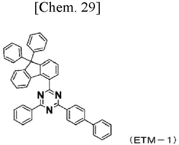

- Examples 14 to 22:
Organic EL devices were produced in the same manner as above, except that the respective compounds obtained in Examples 2 to 10 were used instead of the compound (2-34) obtained in Example 1 used as the material for thecapping layer 11 in Example 13. Properties of the produced organic EL devices were measured in the atmosphere at atmospheric temperature. Measurement results of light emission properties when a direct-current voltage was applied to each of the produced organic EL devices are collectively shown in Table 3. - Device life was measured using the organic EL devices produced in Examples 13 to 22 and Comparative Examples 1 and 2. The results are collectively shown in Table 3. Device life was measured as follows. Constant current driving was performed, with the light emission luminance at the start of light emission (i.e., initial luminance) being 10000 cd/m2, and the time (hours) it took for the light emission luminance to attenuate to 9500 cd/m2 (95% attenuation: amounting to 95% when the initial luminance is considered 100%) was measured.
[Table 3] Compound Voltage [V] (@10 mA/cm2) Luminance [cd/m2] (@10 mA/cm2) Luminous efficiency [cd/A] (@10 mA/cm2) Power efficiency [lm/W] (@10 mA/cm2) Device life, 95% attenuation Example 13 2-34 4.25 12226 122.26 90.38 415 hours Example 14 2-39 4.24 12552 125.52 93.01 432 hours Example 15 2-44 4.24 11834 118.34 87.69 402 hours Example 16 2-52 4.23 12055 120.55 89.54 410 hours Example 17 2-57 4.23 12484 124.84 92.73 415 hours Example 18 2-62 4.23 12330 123.30 91.58 414 hours Example 19 3-31 4.24 12443 124.43 92.20 426 hours Example 20 3-32 4.23 12061 120.61 89.59 402 hours Example 21 3-56 4.25 12001 120.01 88.72 408 hours Example 22 3-57 4.24 11937 119.37 88.45 400 hours Comparative Example 1 CPL-1 4.24 10210 102.10 75.66 304 hours Comparative Example 2 CPL-2 4.24 11234 112.34 83.25 362 hours - As shown in Table 3, the drive voltage at a current density of 10 mA/cm2 was substantially the same for the devices of Comparative Examples 1 and 2 and the devices of Examples 13 to 22. However, the devices of Examples 13 to 22 had improved luminance, luminous efficiency, power efficiency and lifetime, compared to the devices of Comparative Examples 1 and 2. This shows that light extraction efficiency can be significantly improved by containing, in the capping layer, materials according to the present invention that have a high refractive index and are suitably usable in organic EL devices.
- As described above, the arylamine compound having a group represented by the aforementioned formula (1), which is suitably usable in the organic EL device of the present invention, has a high refractive index, and can thus significantly improve light extraction efficiency. Also, the present arylamine compound is stable in a thin-film state, and is thus an excellent compound for use in an organic EL device. By producing an organic EL device by using the present compound and a metal complex as a phosphorescent dopant, high efficiency can be achieved. Further, by using the present compound in a capping layer of an organic EL device, sunlight within a specific wavelength range can be absorbed, thereby preventing impact on materials inside the device and thus improving durability and light resistance. Further, by using the present compound which has no absorption in the blue, green and red wavelength ranges, it is possible to display clear and bright images with excellent color purity. The devices are thus applicable to, for example, household electrical appliances and illumination.


Claims (10)
- An organic electroluminescence device comprising at least an anode, a first hole transport layer, a second hole transport layer, a light-emitting layer, an electron transport layer, a cathode, and a capping layer in this order, wherein:the capping layer contains an arylamine compound having a group represented by the following formula (1); andthe light-emitting layer contains a host and a phosphorescent dopant which is a metal complex containing iridium or platinum:
 Ar1 represents a substituted or unsubstituted aromatic hydrocarbon group, a substituted or unsubstituted aromatic heterocyclic group, or a substituted or unsubstituted fused polycyclic aromatic group;one of R1 to R4 and Ar1 is a linking group as a bonding site;X represents an oxygen atom or a sulfur atom; andR1 to R4 may be bonded to each other via a single bond, a substituted or unsubstituted methylene group, a substituted or unsubstituted amino group, an oxygen atom, or a sulfur atom, to form a ring).
 - The organic electroluminescence device according to claim 1, wherein the arylamine compound having a group represented by the formula (1) is an arylamine compound represented by the following formula (2) or formula (3):


L1 represents a substituted or unsubstituted phenylene group, a substituted or unsubstituted biphenylene group, or a substituted or unsubstituted terphenylene group). - The organic electroluminescence device according to claim 2, wherein the arylamine compound having a group represented by the formula (1) is an arylamine compound represented by the formula (3).
- The organic electroluminescence device according to any one of claims 1 to 3, wherein the host contains a first host compound represented by the following formula (Host-A) and a second host compound represented by the following formula (Host-B):
 R5 to R10 and Ra each independently represent a hydrogen atom, a deuterium atom, a fluorine atom, a chlorine atom, a cyano group, a nitro group, a substituted or unsubstituted alkyl group having 1 to 15 carbon atoms, or a substituted or unsubstituted aryl group having 6 to 12 carbon atoms;L2 and L3 each independently represent a single bond, a substituted or unsubstituted aryl group having 6 to 30 carbon atoms, or a substituted or unsubstituted heteroaryl group having 2 to 30 carbon atoms; andn1 and n2 each independently represent the integer 0 or 1);
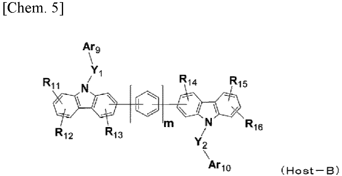 Ar9 and Ar10 each independently represent a substituted or unsubstituted aryl group having 6 to 30 carbon atoms, or a substituted or unsubstituted heteroaryl group having 5 to 30 carbon atoms;R11 to R16 each independently represent a hydrogen atom, a deuterium atom, a fluorine atom, a chlorine atom, a cyano group, a nitro group, an alkyl group having 1 to 15 carbon atoms, a substituted or unsubstituted aryl group having 6 to 30 carbon atoms, or a substituted or unsubstituted heteroaryl group having 5 to 30 carbon atoms; andm represents an integer of 0 to 4).
 - The organic electroluminescence device according to any one of claims 1 to 4, wherein the phosphorescent dopant is a metal complex represented by the following formula (4):

n represents an integer of 1 to 3). - The organic electroluminescence device according to any one of claims 1 to 5, wherein the second hole transport layer contains an arylamine compound represented by the following formula (5):
 R33 to R35, Rb, and Rc each independently represent a hydrogen atom, a deuterium atom, a fluorine atom, a chlorine atom, a cyano group, a nitro group, a substituted or unsubstituted alkyl group having 1 to 15 carbon atoms, or a substituted or unsubstituted aryl group having 6 to 12 carbon atoms; andAr11 and Ar12 each independently represent a substituted or unsubstituted aryl group having 6 to 30 carbon atoms, or a substituted or unsubstituted heteroaryl group having 5 to 30 carbon atoms);
- The organic electroluminescence device according to any one of claims 1 to 6, wherein the capping layer has a thickness within a range of 30 nm to 120 nm.
- The organic electroluminescence device according to any one of claims 1 to 7, wherein the capping layer has a refractive index of 1.85 or greater within a wavelength range of 450 nm to 650 nm.
- An arylamine compound comprising a group represented by the following formula (1):
 Ar1 represents a substituted or unsubstituted aromatic hydrocarbon group, a substituted or unsubstituted aromatic heterocyclic group, or a substituted or unsubstituted fused polycyclic aromatic group;one of R1 to R4 and Ar1 is a linking group as a bonding site;X represents an oxygen atom or a sulfur atom; andR1 to R4 may be bonded to each other via a single bond, a substituted or unsubstituted methylene group, a substituted or unsubstituted amino group, an oxygen atom, or a sulfur atom, to form a ring).
 - The arylamine compound according to claim 9, represented by the following formula (2) or formula (3):


L1 represents a substituted or unsubstituted phenylene group, a substituted or unsubstituted biphenylene group, or a substituted or unsubstituted terphenylene group).
Applications Claiming Priority (2)
| Application Number | Priority Date | Filing Date | Title |
|---|---|---|---|
| JP2019030036 | 2019-02-22 | ||
| PCT/JP2020/007158 WO2020171221A1 (en) | 2019-02-22 | 2020-02-21 | Arylamine compound having benzoazole ring structure, and organic electroluminescent element |
Publications (3)
| Publication Number | Publication Date |
|---|---|
| EP3929193A1 true EP3929193A1 (en) | 2021-12-29 |
| EP3929193A4 EP3929193A4 (en) | 2022-11-30 |
| EP3929193B1 EP3929193B1 (en) | 2024-10-23 |
Family
ID=72144986
Family Applications (1)
| Application Number | Title | Priority Date | Filing Date |
|---|---|---|---|
| EP20759116.5A Active EP3929193B1 (en) | 2019-02-22 | 2020-02-21 | Organic electroluminescent element comprising a capping layer with an arylamine compound having benzoazole ring structure |
Country Status (7)
| Country | Link |
|---|---|
| US (1) | US20220119360A1 (en) |
| EP (1) | EP3929193B1 (en) |
| JP (1) | JP7499748B2 (en) |
| KR (1) | KR102765327B1 (en) |
| CN (1) | CN113382993A (en) |
| TW (1) | TWI857013B (en) |
| WO (1) | WO2020171221A1 (en) |
Cited By (2)
| Publication number | Priority date | Publication date | Assignee | Title |
|---|---|---|---|---|
| EP4210450A3 (en) * | 2022-01-10 | 2023-07-26 | Samsung Display Co., Ltd. | Light-emitting device and electronic apparatus including the same |
| EP4210453A3 (en) * | 2022-01-10 | 2023-10-11 | Samsung Display Co., Ltd. | Light-emitting device and electronic apparatus including the same |
Families Citing this family (14)
| Publication number | Priority date | Publication date | Assignee | Title |
|---|---|---|---|---|
| EP3605638B1 (en) * | 2017-03-28 | 2023-11-08 | Hodogaya Chemical Co., Ltd. | Organic electroluminescent device |
| KR102817317B1 (en) * | 2020-07-22 | 2025-06-10 | 삼성디스플레이 주식회사 | Organic light emitting diode |
| KR20220038911A (en) * | 2020-09-21 | 2022-03-29 | (주)피엔에이치테크 | An organic light emitting diode employing a multi-refractive capping layer for improving a light efficiency |
| US11575087B1 (en) | 2020-12-25 | 2023-02-07 | Idemitsu Kosan Co., Ltd. | Organic electroluminescence device, light emitting device, organic electroluminescence display device and electronic device |
| WO2022138948A1 (en) * | 2020-12-25 | 2022-06-30 | 出光興産株式会社 | Organic electroluminescent element, light emitting device, organic electroluminescent display device, and electronic device |
| US12369490B2 (en) | 2021-01-13 | 2025-07-22 | Idemitsu Kosan Co., Ltd. | Organic electroluminescent element, organic electroluminescent display device, and electronic device |
| CN114989109B (en) * | 2021-03-01 | 2024-01-05 | 武汉天马微电子有限公司 | Compound, material for organic electroluminescent device and application thereof |
| CN114989107B (en) * | 2021-03-01 | 2024-01-09 | 武汉天马微电子有限公司 | Compound, material for organic electroluminescent device and application thereof |
| CN116982405A (en) | 2021-03-12 | 2023-10-31 | 保土谷化学工业株式会社 | Organic electroluminescent components and electronic devices thereof |
| US12349538B2 (en) * | 2021-03-25 | 2025-07-01 | Semiconductor Energy Laboratory Co., Ltd. | Light-emitting device, display device, light-emitting apparatus, electronic device, and lighting device |
| JP2023031178A (en) * | 2021-08-24 | 2023-03-08 | ドンジン セミケム カンパニー リミテッド | Novel organic compound for capping layer and organic light-emitting element including the same |
| CN117343078A (en) | 2021-11-25 | 2024-01-05 | 北京夏禾科技有限公司 | Organic electroluminescent materials and devices |
| CN114057718A (en) * | 2022-01-17 | 2022-02-18 | 浙江华显光电科技有限公司 | Triphenylamine derivative, preparation, organic photoelectric device and display or lighting device |
| CN117384107A (en) * | 2023-10-13 | 2024-01-12 | 潍坊艾迪化工有限公司 | A nitrogen-containing heterobenzene and trifluoromethyl compound and its organic electroluminescent element |
Family Cites Families (29)
| Publication number | Priority date | Publication date | Assignee | Title |
|---|---|---|---|---|
| DE69412567T2 (en) | 1993-11-01 | 1999-02-04 | Hodogaya Chemical Co., Ltd., Tokio/Tokyo | Amine compound and electroluminescent device containing it |
| EP0666298A3 (en) | 1994-02-08 | 1995-11-15 | Tdk Corp | Organic EL element and compound used therein. |
| JP4174989B2 (en) | 1999-11-22 | 2008-11-05 | ソニー株式会社 | Display device |
| JP4460743B2 (en) | 2000-09-29 | 2010-05-12 | 富士フイルム株式会社 | Method for producing iridium complex or tautomer thereof |
| JP2008069120A (en) * | 2006-09-15 | 2008-03-27 | Idemitsu Kosan Co Ltd | Aromatic amine derivatives and organic electroluminescence devices using them |
| US9051274B2 (en) * | 2011-06-24 | 2015-06-09 | Semiconductor Energy Laboratory Co., Ltd. | Triarylamine compound, light-emitting element, light-emitting device, electronic device, and lighting device |
| WO2013038627A1 (en) | 2011-09-12 | 2013-03-21 | 保土谷化学工業株式会社 | Organic electroluminescence element |
| EP2684932B8 (en) | 2012-07-09 | 2016-12-21 | Hodogaya Chemical Co., Ltd. | Diarylamino matrix material doped with a mesomeric radialene compound |
| EP2907173B1 (en) * | 2012-10-09 | 2018-03-21 | Merck Patent GmbH | Electronic device |
| US8946697B1 (en) | 2012-11-09 | 2015-02-03 | Universal Display Corporation | Iridium complexes with aza-benzo fused ligands |
| JP5749870B1 (en) * | 2013-07-03 | 2015-07-15 | 保土谷化学工業株式会社 | Organic electroluminescence device |
| KR101649683B1 (en) | 2013-09-06 | 2016-08-19 | 제일모직 주식회사 | Composition for organic optoelectric device and organic optoelectric device and display device |
| KR101788094B1 (en) | 2014-01-09 | 2017-10-19 | 제일모직 주식회사 | Organic compound and organic optoelectric device and display device |
| CN104795503B (en) * | 2014-01-16 | 2018-07-20 | 三星显示有限公司 | Organic light emitting apparatus |
| JP6374184B2 (en) * | 2014-02-28 | 2018-08-15 | 国立大学法人山形大学 | Triazine derivative and organic light-emitting device using the same |
| KR101835502B1 (en) | 2014-07-21 | 2018-03-07 | 삼성에스디아이 주식회사 | Composition for organic optoelectric device and organic optoelectric device and display device |
| KR20170030427A (en) * | 2015-09-09 | 2017-03-17 | 주식회사 엘지화학 | Organoluminescent device |
| KR101928935B1 (en) * | 2016-02-23 | 2018-12-13 | 주식회사 엘지화학 | Hetero-cyclic compound and organic light emitting device comprising the same |
| KR102164767B1 (en) * | 2016-04-12 | 2020-10-14 | 주식회사 엘지화학 | Capping layer comprising an organic compound and organic electroluminescent device comprising the same |
| JPWO2017183625A1 (en) * | 2016-04-22 | 2019-02-28 | 保土谷化学工業株式会社 | Organic electroluminescence device |
| CN107868067B (en) * | 2016-09-28 | 2021-06-15 | 株式会社Lg化学 | Heterocyclic compound and organic light-emitting element including the same |
| US20180093962A1 (en) | 2016-10-05 | 2018-04-05 | Sfc Co., Ltd. | Novel organic compound and oranic light-emitting diode comprising same background of the invention |
| CN107973786B (en) * | 2016-10-25 | 2021-07-09 | 株式会社Lg化学 | Novel compound and organic light-emitting element using the same |
| KR102078301B1 (en) * | 2017-07-12 | 2020-02-17 | 주식회사 엘지화학 | Novel compound and organic light emitting device comprising the same |
| EP3731599B1 (en) * | 2017-12-21 | 2023-05-03 | Hodogaya Chemical Co., Ltd. | Organic electroluminescence element |
| KR102099171B1 (en) * | 2017-12-29 | 2020-04-09 | (주)랩토 | Aryl amine derivatieves and organic electroluminescent device including the same |
| KR102059550B1 (en) * | 2018-12-12 | 2019-12-26 | (주)랩토 | Tribenzazole amine derivatives and organic electroluminescent device including the same |
| KR102743517B1 (en) * | 2018-12-25 | 2024-12-16 | 호도가야 가가쿠 고교 가부시키가이샤 | Organic electroluminescent devices |
| KR20220124697A (en) * | 2020-01-08 | 2022-09-14 | 호도가야 가가쿠 고교 가부시키가이샤 | organic electroluminescent device |
-
2020
- 2020-02-21 KR KR1020217024115A patent/KR102765327B1/en active Active
- 2020-02-21 JP JP2021502203A patent/JP7499748B2/en active Active
- 2020-02-21 TW TW109105768A patent/TWI857013B/en active
- 2020-02-21 WO PCT/JP2020/007158 patent/WO2020171221A1/en not_active Ceased
- 2020-02-21 CN CN202080011823.8A patent/CN113382993A/en active Pending
- 2020-02-21 US US17/427,772 patent/US20220119360A1/en not_active Abandoned
- 2020-02-21 EP EP20759116.5A patent/EP3929193B1/en active Active
Cited By (4)
| Publication number | Priority date | Publication date | Assignee | Title |
|---|---|---|---|---|
| EP4210450A3 (en) * | 2022-01-10 | 2023-07-26 | Samsung Display Co., Ltd. | Light-emitting device and electronic apparatus including the same |
| EP4210453A3 (en) * | 2022-01-10 | 2023-10-11 | Samsung Display Co., Ltd. | Light-emitting device and electronic apparatus including the same |
| US12389792B2 (en) | 2022-01-10 | 2025-08-12 | Samsung Display Co., Ltd. | Light-emitting device and electronic apparatus including the same |
| EP4601448A3 (en) * | 2022-01-10 | 2025-09-24 | Samsung Display Co., Ltd. | Light-emitting device and electronic apparatus including the same |
Also Published As
| Publication number | Publication date |
|---|---|
| CN113382993A (en) | 2021-09-10 |
| KR20210131321A (en) | 2021-11-02 |
| EP3929193A4 (en) | 2022-11-30 |
| WO2020171221A1 (en) | 2020-08-27 |
| EP3929193B1 (en) | 2024-10-23 |
| TWI857013B (en) | 2024-10-01 |
| JP7499748B2 (en) | 2024-06-14 |
| TW202041503A (en) | 2020-11-16 |
| KR102765327B1 (en) | 2025-02-07 |
| US20220119360A1 (en) | 2022-04-21 |
| JPWO2020171221A1 (en) | 2021-12-16 |
Similar Documents
| Publication | Publication Date | Title |
|---|---|---|
| EP3929193B1 (en) | Organic electroluminescent element comprising a capping layer with an arylamine compound having benzoazole ring structure | |
| KR102695099B1 (en) | Organic electroluminescent devices | |
| EP3432688B1 (en) | Organic electroluminescence element | |
| KR101937259B1 (en) | Styrly-based compound, composition containding the styryl-based compound and organic light emitting diode comprising the same | |
| EP3941159B1 (en) | Organic electroluminescence element | |
| KR20160143483A (en) | Material for organic electroluminescent device and organic electroluminescent device including the same | |
| EP4357349A1 (en) | Amine compound having azabenzoxazole ring structure, and organic electroluminescent element using same | |
| KR20160041744A (en) | Organic electroluminescent device | |
| JP7163311B2 (en) | organic electroluminescence element | |
| KR102651663B1 (en) | Compounds having an indenocarbazole ring structure and organic electroluminescent devices | |
| EP4424682A1 (en) | Amine compound and organic electroluminescent element using same | |
| US12481844B2 (en) | Organic electroluminescent element, electronic device, and compound |
Legal Events
| Date | Code | Title | Description |
|---|---|---|---|
| STAA | Information on the status of an ep patent application or granted ep patent |
Free format text: STATUS: THE INTERNATIONAL PUBLICATION HAS BEEN MADE |
|
| PUAI | Public reference made under article 153(3) epc to a published international application that has entered the european phase |
Free format text: ORIGINAL CODE: 0009012 |
|
| STAA | Information on the status of an ep patent application or granted ep patent |
Free format text: STATUS: REQUEST FOR EXAMINATION WAS MADE |
|
| 17P | Request for examination filed |
Effective date: 20210716 |
|
| AK | Designated contracting states |
Kind code of ref document: A1 Designated state(s): AL AT BE BG CH CY CZ DE DK EE ES FI FR GB GR HR HU IE IS IT LI LT LU LV MC MK MT NL NO PL PT RO RS SE SI SK SM TR |
|
| DAV | Request for validation of the european patent (deleted) | ||
| DAX | Request for extension of the european patent (deleted) | ||
| A4 | Supplementary search report drawn up and despatched |
Effective date: 20221102 |
|
| RIC1 | Information provided on ipc code assigned before grant |
Ipc: C09K 11/06 20060101ALN20221026BHEP Ipc: C07D 251/24 20060101ALI20221026BHEP Ipc: C07D 277/66 20060101ALI20221026BHEP Ipc: C07D 263/62 20060101ALI20221026BHEP Ipc: C07D 209/82 20060101ALI20221026BHEP Ipc: C07D 405/14 20060101ALI20221026BHEP Ipc: H01L 51/54 20060101AFI20221026BHEP |
|
| GRAP | Despatch of communication of intention to grant a patent |
Free format text: ORIGINAL CODE: EPIDOSNIGR1 |
|
| STAA | Information on the status of an ep patent application or granted ep patent |
Free format text: STATUS: GRANT OF PATENT IS INTENDED |
|
| INTG | Intention to grant announced |
Effective date: 20240712 |
|
| RIC1 | Information provided on ipc code assigned before grant |
Ipc: H10K 101/10 20230101ALN20240705BHEP Ipc: H10K 50/11 20230101ALN20240705BHEP Ipc: C09K 11/06 20060101ALN20240705BHEP Ipc: H10K 85/30 20230101ALI20240705BHEP Ipc: H10K 50/858 20230101ALI20240705BHEP Ipc: H10K 85/60 20230101ALI20240705BHEP Ipc: H10K 50/844 20230101ALI20240705BHEP Ipc: C07D 251/24 20060101ALI20240705BHEP Ipc: C07D 277/66 20060101ALI20240705BHEP Ipc: C07D 263/62 20060101ALI20240705BHEP Ipc: C07D 209/82 20060101ALI20240705BHEP Ipc: C07D 405/14 20060101AFI20240705BHEP |
|
| GRAS | Grant fee paid |
Free format text: ORIGINAL CODE: EPIDOSNIGR3 |
|
| GRAA | (expected) grant |
Free format text: ORIGINAL CODE: 0009210 |
|
| STAA | Information on the status of an ep patent application or granted ep patent |
Free format text: STATUS: THE PATENT HAS BEEN GRANTED |
|
| P01 | Opt-out of the competence of the unified patent court (upc) registered |
Free format text: CASE NUMBER: APP_48356/2024 Effective date: 20240822 |
|
| AK | Designated contracting states |
Kind code of ref document: B1 Designated state(s): AL AT BE BG CH CY CZ DE DK EE ES FI FR GB GR HR HU IE IS IT LI LT LU LV MC MK MT NL NO PL PT RO RS SE SI SK SM TR |
|
| REG | Reference to a national code |
Ref country code: GB Ref legal event code: FG4D |
|
| REG | Reference to a national code |
Ref country code: CH Ref legal event code: EP |
|
| REG | Reference to a national code |
Ref country code: DE Ref legal event code: R096 Ref document number: 602020039934 Country of ref document: DE |
|
| REG | Reference to a national code |
Ref country code: IE Ref legal event code: FG4D |
|
| REG | Reference to a national code |
Ref country code: LT Ref legal event code: MG9D |
|
| REG | Reference to a national code |
Ref country code: NL Ref legal event code: MP Effective date: 20241023 |
|
| REG | Reference to a national code |
Ref country code: AT Ref legal event code: MK05 Ref document number: 1734763 Country of ref document: AT Kind code of ref document: T Effective date: 20241023 |
|
| PG25 | Lapsed in a contracting state [announced via postgrant information from national office to epo] |
Ref country code: NL Free format text: LAPSE BECAUSE OF FAILURE TO SUBMIT A TRANSLATION OF THE DESCRIPTION OR TO PAY THE FEE WITHIN THE PRESCRIBED TIME-LIMIT Effective date: 20241023 |
|
| PG25 | Lapsed in a contracting state [announced via postgrant information from national office to epo] |
Ref country code: NL Free format text: LAPSE BECAUSE OF FAILURE TO SUBMIT A TRANSLATION OF THE DESCRIPTION OR TO PAY THE FEE WITHIN THE PRESCRIBED TIME-LIMIT Effective date: 20241023 |
|
| PG25 | Lapsed in a contracting state [announced via postgrant information from national office to epo] |
Ref country code: PT Free format text: LAPSE BECAUSE OF FAILURE TO SUBMIT A TRANSLATION OF THE DESCRIPTION OR TO PAY THE FEE WITHIN THE PRESCRIBED TIME-LIMIT Effective date: 20250224 Ref country code: HR Free format text: LAPSE BECAUSE OF FAILURE TO SUBMIT A TRANSLATION OF THE DESCRIPTION OR TO PAY THE FEE WITHIN THE PRESCRIBED TIME-LIMIT Effective date: 20241023 Ref country code: IS Free format text: LAPSE BECAUSE OF FAILURE TO SUBMIT A TRANSLATION OF THE DESCRIPTION OR TO PAY THE FEE WITHIN THE PRESCRIBED TIME-LIMIT Effective date: 20250223 |
|
| PG25 | Lapsed in a contracting state [announced via postgrant information from national office to epo] |
Ref country code: FI Free format text: LAPSE BECAUSE OF FAILURE TO SUBMIT A TRANSLATION OF THE DESCRIPTION OR TO PAY THE FEE WITHIN THE PRESCRIBED TIME-LIMIT Effective date: 20241023 |
|
| PG25 | Lapsed in a contracting state [announced via postgrant information from national office to epo] |
Ref country code: BG Free format text: LAPSE BECAUSE OF FAILURE TO SUBMIT A TRANSLATION OF THE DESCRIPTION OR TO PAY THE FEE WITHIN THE PRESCRIBED TIME-LIMIT Effective date: 20241023 |
|
| PG25 | Lapsed in a contracting state [announced via postgrant information from national office to epo] |
Ref country code: ES Free format text: LAPSE BECAUSE OF FAILURE TO SUBMIT A TRANSLATION OF THE DESCRIPTION OR TO PAY THE FEE WITHIN THE PRESCRIBED TIME-LIMIT Effective date: 20241023 |
|
| PG25 | Lapsed in a contracting state [announced via postgrant information from national office to epo] |
Ref country code: NO Free format text: LAPSE BECAUSE OF FAILURE TO SUBMIT A TRANSLATION OF THE DESCRIPTION OR TO PAY THE FEE WITHIN THE PRESCRIBED TIME-LIMIT Effective date: 20250123 |
|
| PG25 | Lapsed in a contracting state [announced via postgrant information from national office to epo] |
Ref country code: LV Free format text: LAPSE BECAUSE OF FAILURE TO SUBMIT A TRANSLATION OF THE DESCRIPTION OR TO PAY THE FEE WITHIN THE PRESCRIBED TIME-LIMIT Effective date: 20241023 Ref country code: AT Free format text: LAPSE BECAUSE OF FAILURE TO SUBMIT A TRANSLATION OF THE DESCRIPTION OR TO PAY THE FEE WITHIN THE PRESCRIBED TIME-LIMIT Effective date: 20241023 Ref country code: GR Free format text: LAPSE BECAUSE OF FAILURE TO SUBMIT A TRANSLATION OF THE DESCRIPTION OR TO PAY THE FEE WITHIN THE PRESCRIBED TIME-LIMIT Effective date: 20250124 |
|
| PG25 | Lapsed in a contracting state [announced via postgrant information from national office to epo] |
Ref country code: PL Free format text: LAPSE BECAUSE OF FAILURE TO SUBMIT A TRANSLATION OF THE DESCRIPTION OR TO PAY THE FEE WITHIN THE PRESCRIBED TIME-LIMIT Effective date: 20241023 |
|
| PG25 | Lapsed in a contracting state [announced via postgrant information from national office to epo] |
Ref country code: RS Free format text: LAPSE BECAUSE OF FAILURE TO SUBMIT A TRANSLATION OF THE DESCRIPTION OR TO PAY THE FEE WITHIN THE PRESCRIBED TIME-LIMIT Effective date: 20250123 |
|
| PG25 | Lapsed in a contracting state [announced via postgrant information from national office to epo] |
Ref country code: SM Free format text: LAPSE BECAUSE OF FAILURE TO SUBMIT A TRANSLATION OF THE DESCRIPTION OR TO PAY THE FEE WITHIN THE PRESCRIBED TIME-LIMIT Effective date: 20241023 |
|
| PG25 | Lapsed in a contracting state [announced via postgrant information from national office to epo] |
Ref country code: DK Free format text: LAPSE BECAUSE OF FAILURE TO SUBMIT A TRANSLATION OF THE DESCRIPTION OR TO PAY THE FEE WITHIN THE PRESCRIBED TIME-LIMIT Effective date: 20241023 |
|
| PG25 | Lapsed in a contracting state [announced via postgrant information from national office to epo] |
Ref country code: EE Free format text: LAPSE BECAUSE OF FAILURE TO SUBMIT A TRANSLATION OF THE DESCRIPTION OR TO PAY THE FEE WITHIN THE PRESCRIBED TIME-LIMIT Effective date: 20241023 |
|
| PG25 | Lapsed in a contracting state [announced via postgrant information from national office to epo] |
Ref country code: RO Free format text: LAPSE BECAUSE OF FAILURE TO SUBMIT A TRANSLATION OF THE DESCRIPTION OR TO PAY THE FEE WITHIN THE PRESCRIBED TIME-LIMIT Effective date: 20241023 |
|
| REG | Reference to a national code |
Ref country code: DE Ref legal event code: R097 Ref document number: 602020039934 Country of ref document: DE |
|
| PG25 | Lapsed in a contracting state [announced via postgrant information from national office to epo] |
Ref country code: SK Free format text: LAPSE BECAUSE OF FAILURE TO SUBMIT A TRANSLATION OF THE DESCRIPTION OR TO PAY THE FEE WITHIN THE PRESCRIBED TIME-LIMIT Effective date: 20241023 |
|
| PG25 | Lapsed in a contracting state [announced via postgrant information from national office to epo] |
Ref country code: CZ Free format text: LAPSE BECAUSE OF FAILURE TO SUBMIT A TRANSLATION OF THE DESCRIPTION OR TO PAY THE FEE WITHIN THE PRESCRIBED TIME-LIMIT Effective date: 20241023 |
|
| PG25 | Lapsed in a contracting state [announced via postgrant information from national office to epo] |
Ref country code: IT Free format text: LAPSE BECAUSE OF FAILURE TO SUBMIT A TRANSLATION OF THE DESCRIPTION OR TO PAY THE FEE WITHIN THE PRESCRIBED TIME-LIMIT Effective date: 20241023 |
|
| PLBE | No opposition filed within time limit |
Free format text: ORIGINAL CODE: 0009261 |
|
| STAA | Information on the status of an ep patent application or granted ep patent |
Free format text: STATUS: NO OPPOSITION FILED WITHIN TIME LIMIT |
|
| PG25 | Lapsed in a contracting state [announced via postgrant information from national office to epo] |
Ref country code: SE Free format text: LAPSE BECAUSE OF FAILURE TO SUBMIT A TRANSLATION OF THE DESCRIPTION OR TO PAY THE FEE WITHIN THE PRESCRIBED TIME-LIMIT Effective date: 20241023 |
|
| PG25 | Lapsed in a contracting state [announced via postgrant information from national office to epo] |
Ref country code: MC Free format text: LAPSE BECAUSE OF FAILURE TO SUBMIT A TRANSLATION OF THE DESCRIPTION OR TO PAY THE FEE WITHIN THE PRESCRIBED TIME-LIMIT Effective date: 20241023 |
|
| REG | Reference to a national code |
Ref country code: CH Ref legal event code: PL |
|
| 26N | No opposition filed |
Effective date: 20250724 |
|
| PG25 | Lapsed in a contracting state [announced via postgrant information from national office to epo] |
Ref country code: LU Free format text: LAPSE BECAUSE OF NON-PAYMENT OF DUE FEES Effective date: 20250221 |
|
| PG25 | Lapsed in a contracting state [announced via postgrant information from national office to epo] |
Ref country code: CH Free format text: LAPSE BECAUSE OF NON-PAYMENT OF DUE FEES Effective date: 20250228 |
|
| GBPC | Gb: european patent ceased through non-payment of renewal fee |
Effective date: 20250221 |
|
| REG | Reference to a national code |
Ref country code: BE Ref legal event code: MM Effective date: 20250228 |
|
| PG25 | Lapsed in a contracting state [announced via postgrant information from national office to epo] |
Ref country code: GB Free format text: LAPSE BECAUSE OF NON-PAYMENT OF DUE FEES Effective date: 20250221 |
|
| PG25 | Lapsed in a contracting state [announced via postgrant information from national office to epo] |
Ref country code: FR Free format text: LAPSE BECAUSE OF NON-PAYMENT OF DUE FEES Effective date: 20250228 |
|
| PG25 | Lapsed in a contracting state [announced via postgrant information from national office to epo] |
Ref country code: BE Free format text: LAPSE BECAUSE OF NON-PAYMENT OF DUE FEES Effective date: 20250228 |
|
| PG25 | Lapsed in a contracting state [announced via postgrant information from national office to epo] |
Ref country code: IE Free format text: LAPSE BECAUSE OF NON-PAYMENT OF DUE FEES Effective date: 20250221 |
|
| PGFP | Annual fee paid to national office [announced via postgrant information from national office to epo] |
Ref country code: DE Payment date: 20260204 Year of fee payment: 7 |