EP3929136A1 - Hoistway access ladder storage - Google Patents
Hoistway access ladder storage Download PDFInfo
- Publication number
- EP3929136A1 EP3929136A1 EP20305709.6A EP20305709A EP3929136A1 EP 3929136 A1 EP3929136 A1 EP 3929136A1 EP 20305709 A EP20305709 A EP 20305709A EP 3929136 A1 EP3929136 A1 EP 3929136A1
- Authority
- EP
- European Patent Office
- Prior art keywords
- access ladder
- hoistway
- landing
- elevator
- rotating support
- Prior art date
- Legal status (The legal status is an assumption and is not a legal conclusion. Google has not performed a legal analysis and makes no representation as to the accuracy of the status listed.)
- Granted
Links
Images



Classifications
-
- B—PERFORMING OPERATIONS; TRANSPORTING
- B66—HOISTING; LIFTING; HAULING
- B66B—ELEVATORS; ESCALATORS OR MOVING WALKWAYS
- B66B5/00—Applications of checking, fault-correcting, or safety devices in elevators
- B66B5/0087—Devices facilitating maintenance, repair or inspection tasks
-
- B—PERFORMING OPERATIONS; TRANSPORTING
- B66—HOISTING; LIFTING; HAULING
- B66B—ELEVATORS; ESCALATORS OR MOVING WALKWAYS
- B66B13/00—Doors, gates, or other apparatus controlling access to, or exit from, cages or lift well landings
- B66B13/02—Door or gate operation
- B66B13/06—Door or gate operation of sliding doors
- B66B13/08—Door or gate operation of sliding doors guided for horizontal movement
-
- B—PERFORMING OPERATIONS; TRANSPORTING
- B66—HOISTING; LIFTING; HAULING
- B66B—ELEVATORS; ESCALATORS OR MOVING WALKWAYS
- B66B13/00—Doors, gates, or other apparatus controlling access to, or exit from, cages or lift well landings
- B66B13/30—Constructional features of doors or gates
- B66B13/306—Details of door jambs
-
- B—PERFORMING OPERATIONS; TRANSPORTING
- B66—HOISTING; LIFTING; HAULING
- B66B—ELEVATORS; ESCALATORS OR MOVING WALKWAYS
- B66B7/00—Other common features of elevators
-
- B—PERFORMING OPERATIONS; TRANSPORTING
- B66—HOISTING; LIFTING; HAULING
- B66B—ELEVATORS; ESCALATORS OR MOVING WALKWAYS
- B66B9/00—Kinds or types of lifts in, or associated with, buildings or other structures
-
- E—FIXED CONSTRUCTIONS
- E06—DOORS, WINDOWS, SHUTTERS, OR ROLLER BLINDS IN GENERAL; LADDERS
- E06C—LADDERS
- E06C9/00—Ladders characterised by being permanently attached to fixed structures, e.g. fire escapes
- E06C9/06—Ladders characterised by being permanently attached to fixed structures, e.g. fire escapes movably mounted
- E06C9/08—Ladders characterised by being permanently attached to fixed structures, e.g. fire escapes movably mounted with rigid longitudinal members
- E06C9/085—Ladders characterised by being permanently attached to fixed structures, e.g. fire escapes movably mounted with rigid longitudinal members ladders unfolded in the direction of the longitudinal members
Definitions
- This disclosure generally relates to storage systems for a hoistway access ladder for an elevator system. This is achieved by storing a ladder inside a column of a hoistway landing door, or in a support mounted to a door column, to ensure the hoistway access ladder can be safely accessed by maintenance personnel from a landing regardless of the dimensions of the hoistway.
- a dedicated hoistway access ladder to be provided for use in an elevator hoistway, for example to access the elevator pit or elevator car for repairs or maintenance.
- the hoistway ladder apparatus is located in the elevator hoistway in a retracted position, e.g. mounted on a wall of the hoistway, from which it must be retrieved in the event that maintenance is required to be carried out.
- the dimensions of the hoistway must be such that sufficient space for the hoistway access ladder is available.
- maintenance personnel may be required to use other equipment, such as ropes or bars, to safely retrieve the hoistway access ladder, the requirements of which will vary depending on the size of the hoistway.
- the present disclosure seeks to provide an alternative approach.
- an elevator hoistway access ladder storage system comprising a hoistway access ladder and a landing doorway, the landing doorway comprising a door column and a landing door, wherein the door column comprises a cavity, and wherein the hoistway access ladder is stored within the cavity of the door column.
- a hoistway access ladder can be stored in and safely retrieved from the cavity by an operator on the landing without risking the safety of the operator, and without the use of additional equipment such as ropes or bars.
- the elevator hoistway access ladder storage system further comprises at least one restraining element arranged to hold the hoistway access ladder in the interior of the cavity.
- the elevator hoistway access ladder storage system further comprises a rotating support mounted to the door column to support the hoistway access ladder within the cavity.
- a rotating support mounted to the door column to support the hoistway access ladder within the cavity.
- the use of such a rotating support allows the hoistway access ladder to be accessed more easily by an operator, e.g. by moving the rotating support in and out of the cavity.
- the Applicant has realised that such a rotating support can provide for more easy retrieval of a hoistway access ladder regardless of whether the hoistway access ladder is stored within the cavity as described above, or elsewhere in the elevator hoistway.
- an elevator hoistway access ladder storage system comprising a landing doorway, the landing doorway comprising a door column and a landing door, wherein the door column comprises a rotating support for storing a hoistway access ladder, the rotating support being rotatable relative to the door column.
- a hoistway access ladder can be stored in and safely retrieved from the rotating support by an operator on the landing without risking the safety of the operator, by rotating the rotating support to a convenient position for the operator to reach the hoistway access ladder. This may avoid the need for additional equipment such as ropes or bars.
- the door column of the elevator hoistway access ladder storage system comprises a cavity, and the rotating support is rotatable between a first position inside the cavity, and a second position inside the landing doorway.
- the rotating support of the elevator hoistway access ladder storage system comprises at least one retaining element arranged to hold a hoistway access ladder in a storage position in the rotating support during use.
- the use of a retaining element ensures that the hoistway access ladder remains within the rotating support when it is rotated between the first and second positions.
- the at least one restraining element mentioned above in relation to the first aspect of the present disclosure may be replaced by the at least one retaining element of the rotating support.
- the elevator hoistway access ladder storage system includes the at least one retaining element arranged to hold the hoistway access ladder in a storage position in the rotating support during use, and at least one restraining element arranged to hold the rotating support in the interior of the cavity when in the first position.
- the rotating support may itself be held in its first position in the cavity.
- the landing door of the elevator hoistway access ladder storage system is a side opening door. In one or more examples of the present disclosure, the landing door of the elevator hoistway access ladder storage system is a telescopic side opening door. The use of a side opening door in the system of the present disclosure simplifies access to the hoistway access ladder that may otherwise be at least partially blocked when central opening landing doors are used.
- the hoistway access ladder of the elevator hoistway access ladder storage system is a foldable ladder. While the system of the present disclosure can in principle be used with many kinds of folding ladder, in one or more examples of the present disclosure, the hoistway access ladder of the elevator hoistway access ladder storage system is a foldable ladder comprising a pair of uprights connected by rungs, and the hoistway access ladder is foldable into a storage configuration by moving the uprights together.
- an elevator system comprising an elevator car arranged to move in an elevator hoistway, and at least one landing in the hoistway comprising a landing doorway, wherein the landing doorway comprises the elevator hoistway access ladder storage system as described in any of the previously described examples.
- the landing doorway of the elevator system is situated at a lowermost landing of the elevator hoistway.
- the hoistway access ladder storage system may be used to store an elevator hoistway access ladder for access to an elevator pit, i.e. a pit access ladder.
- the cavity may pre-exist in the door column or the cavity may be formed in the door column when creating the elevator hoistway access ladder storage system.
- the cavity extends vertically along the door column.
- the cavity may extend along at least 50%, 60%, 70%, 80%, or 90% of the height of the door column.
- the cavity is an open-sided channel, for example an open-sided channel having a width and/or depth much smaller than its length.
- the cavity and the hoistway access ladder may be dimensioned to match, such that the hoistway access ladder substantially fills the cavity.
- a method of storing a hoistway access ladder in a landing doorway of an elevator hoistway comprising storing a hoistway access ladder in a cavity of a door column of a landing doorway.
- the Applicant has realised that at least some existing elevator systems include landing doorways comprising door columns in which there is a pre-existing cavity.
- the Applicant has realised that such a door column cavity can advantageously be used to store a hoistway access ladder.
- a rotating support for the hoistway access ladder (e.g. as described above) is retrofitted to such a door column.
- a method of storing a hoistway access ladder in a landing doorway of an elevator hoistway comprising: mounting a rotating support to a door column of a landing doorway, the rotating support being rotatable relative to the door column; and storing a hoistway access ladder in the rotating support.
- Mounting or retrofitting a rotating support to a door column of a landing doorway may allow pre-existing elevator systems to be modified to enable safe and convenient storage of a hoistway access ladder, regardless of whether the door column includes a cavity or not.
- the rotating support may therefore be mounted during installation of the door column or at a later point in time.
- the door column comprises a cavity
- the method further comprises mounting the rotating support to rotate between a first position within the cavity to a second position inside the landing doorway. Mounting the rotating support such that it can be positioned within a cavity of a door column reduces the amount of space required in the elevator hoistway that would otherwise be taken up by the rotating support.
- at least some existing elevator systems include landing doorways comprising door columns in which there is a pre-existing cavity.
- the Applicant has realised that such a door column cavity can be used to conveniently position a rotating support e.g. in a hidden position within the cavity to store the hoistway access ladder out of sight.
- a rotating support may be mounted or retrofitted to the door column of pre-existing elevator systems, improving operator safety when retrieving the hoistway access ladder.
- the rotating support is mounted to a door column of a landing doorway situated at a lowermost landing of an elevator hoistway and the hoistway access ladder is a pit access ladder.
- Such retrofitting methods provide a rotating support that makes it easier to store and retrieve a pit access ladder, for example for use in elevator hoistways that have a pit depth of less than 2.5 m.
- Figure 1 is a perspective view of an elevator system 101 including an elevator car 103, a counterweight 105, one or more load bearing members 107, a guide rail 109, a machine 111, a position encoder 113, and an elevator controller 115.
- the elevator car 103 and counterweight 105 are connected to each other by the load bearing members 107.
- the load bearing members 107 may be, for example, ropes, steel cables, and/or coated-steel belts.
- the counterweight 105 is configured to balance a load of the elevator car 103 and is configured to facilitate movement of the elevator car 103 concurrently and in an opposite direction with respect to the counterweight 105 within an elevator hoistway 117 and along the guide rail 109.
- the load bearing members 107 engage the machine 111, which is part of an overhead structure of the elevator system 101.
- the machine 111 is configured to control movement between the elevator car 103 and the counterweight 105.
- the elevator controller 115 is located, as shown, in a controller room 121 of the elevator hoistway 117 and is configured to control the operation of the elevator system 101, and particularly the elevator car 103.
- the elevator controller 115 may provide drive signals to the machine 111 to control the acceleration, deceleration, levelling, stopping, etc. of the elevator car 103.
- the elevator controller 115 may also be configured to receive position signals from the position encoder 113.
- the elevator car 103 may stop at one or more landings 125 as controlled by the elevator controller 115.
- the machine 111 may include a motor or similar driving mechanism and an optional braking system. Although shown and described with a rope-based load bearing system, elevator systems that employ other methods and mechanisms of moving an elevator car within an elevator hoistway, such as hydraulics, ropeless, or any other methods, are also examples of the present disclosure.
- FIG. 1 is merely a nonlimiting example presented for illustrative and explanatory purposes.
- the elevator pit 127 At the bottom of the elevator hoistway 117, below the lowermost landing 129, is the elevator pit 127. It is often necessary for the elevator pit 127 to be accessed by maintenance personnel in order for inspection or repairs to be carried out. In elevator systems without pit access doors at the bottom of the hoistway, the distance between the lowermost landing 129 and the elevator pit 127 may be up to 2.5 m. For the elevator pit 127 to be accessed safely from the lowermost landing 129, equipment needs to be provided to allow the elevator pit 127 to be accessed. The most common way access is provided is using an elevator hoistway access ladder, such as hoistway access ladder 200 shown in Figure 2 .
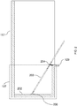
- FIG. 2 shows an elevator hoistway 117, and elevator pit 127, in which a hoistway access ladder 200 is deployed.
- the hoistway access ladder 200 provides access to the floor 202 of the elevator hoistway 117 from the lowermost landing 129.
- the hoistway access ladder 200 is secured at the lowermost landing 129 and the floor 202 of the elevator hoistway 117 by securing means 204, 206.
- Figure 2 illustrates a hoistway access ladder 200 being used to provide access to an elevator pit 127 from the lowermost landing 129
- the hoistway access ladder 200 could also be used at any other landing 125 within the hoistway 117 to provide access to other areas of the hoistway 117.
- the hoistway access ladder 200 may be used to access the roof of an elevator car (e.g. elevator car 103 of Figure 1 ) from any appropriate landing 125.
- hoistway access ladders are typically stored close to or within the hoistway, and are typically foldable or retractable in order to limit the amount of storage space required within the hoistway. The design of hoistway access ladders is therefore dependent on the storage method used.
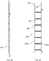
- FIG. 3A An exemplary hoistway access ladder 300 suitable for use in the systems of the present disclosure is shown in Figures 3A and 3B .
- the hoistway access ladder 300 comprises uprights 302a, 302b connected by rungs 304, and a locking hinge 306.
- Locking hinge 306 allows the ladder to be folded between a deployed configuration (shown in Figure 3B ), and a storage configuration (shown in Figure 3A ).
- Figure 3A in the storage configuration, the uprights 302a and 302b are moved together.
- the uprights 302a and 302b become offset, and the uprights 302a and 302b become aligned when the hoistway access ladder 300 is folded out to the deployed configuration shown in Figure 3B .
- the locking hinge 306 holds the hoistway access ladder 300 open such that it can be safely used by maintenance personnel.
- applying relative motion between uprights 302a and 302b causes the hinge to unlock and the uprights 302a and 302b to move together, such that the uprights 302a and 302b come into contact.
- the rungs 304 may be hinged or collapsible.
- the rungs 304 are configured to rotate relative to the uprights around a point 308, however in other examples the rungs 304 of the hoistway access ladder 300 may instead be telescopic or may be collapsible by other appropriate means.
- the hoistway access ladder 300 is required to be stored close to the elevator hoistway 117 when not in use.
- hoistway access ladders are typically stored within the hoistway itself, for example mounted to one of the hoistway walls.
- storage for a hoistway access ladder 300 can advantageously be provided in a cavity provided within a door column of the doorway of a landing 125, or in a support mounted to a door column of a landing doorway, as is described further below.
- Figures 4A-4D show a hoistway access ladder storage system 400 according to a first example of the present disclosure.
- Figures 4A-4D each show a landing doorway 402, which may be present at the lowermost landing 129 of the elevator hoistway 117 seen in Figs. 1 and 2 .
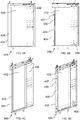
- Figures 4A and 4B show a side view of the hoistway access ladder storage system 400 as viewed from the hoistway side, i.e. the rear of the landing doorway 402.
- Figures 4C and 4D show an isometric view of the rear side of the hoistway access ladder storage system 400.
- the landing doorway 402 comprises a door column 404 and a landing door 406.
- the landing door 406 is a telescopic landing door, however any side opening landing door could be used.
- a door column 404 is present on at least one side of the landing doorway 402. In this example, the door column 404 is part of a jamb for the landing door 406.
- the Applicant has realised that the door column 404 can be advantageously made suitable for storing a hoistway access ladder 300, providing access to the hoistway access ladder 300 safely and conveniently, without requiring substantive modification to existing elevator systems.
- the door column 404 comprises a cavity 405, which has dimensions suitable for storing the hoistway access ladder 300.
- Figures 4A and 4C show the hoistway access ladder storage system 400 with the cavity 405 empty, while Figures 4B and 4D show the hoistway access ladder storage system 400 with the cavity 405 containing the hoistway access ladder 300.
- the hoistway access ladder 300 may be stored in the cavity 405 of the door column 404 without the use of any restraining devices, however in the first example the hoistway access ladder 300 is held within the cavity 405 using a restraining element 407 (seen in Figs. 4B and 4D ), such as a strap or a locking bar. After unlocking or removing the restraining element 407, the hoistway access ladder 300 can simply be lifted out of the cavity 405 when it is required for use. For example, when a maintenance operation such as a pit inspection is carried out, the landing door 406 is opened from the landing side (i.e. the front of the landing door), leaving the doorway 402 open.
- a restraining element 407 such as a strap or a locking bar.
- the hoistway access ladder 300 can then simply be lifted out from the cavity 405 by, e.g. a technician, by reaching through the doorway 402 from the landing side and accessing the cavity 405 on the hoistway side. This allows the hoistway access ladder 300 to be accessed without dangerously reaching out into the hoistway, for example to retrieve an access ladder from a wall of the hoistway, as is known in the prior art. The risk to maintenance personnel in accessing the hoistway access ladder 300 is therefore reduced.
- the hoistway access ladder 300 is stored in a different configuration, in which ease of access to the hoistway access ladder is further improved in at least some cases.
- Figures 5A and 5B show a side view of a hoistway access ladder storage system 500 according to a second example of this disclosure.
- Figures 5A and 5B show a landing doorway 502, as may be employed at the lowermost landing 129 of the elevator hoistway 117 shown in Figures 1 and 2 , as viewed from the hoistway side, i.e. the rear of the landing doorway 502.
- the landing doorway 502 comprises a door column 504 and a side opening landing door 506.
- the door column 504 comprises a cavity 505, which has dimensions suitable for storing the hoistway access ladder 300.
- Figure 5A shows the hoistway access ladder storage system 500 with the cavity 505 empty
- Figure 5B shows the hoistway access ladder storage system 500 with the hoistway access ladder 300 contained within the cavity 505.
- the rotating support 501 mounted to the door column 504 in which the hoistway access ladder 300 can be stored to provide easier retrieval of the hoistway access ladder 300.
- the rotating support 501 is configured to sit entirely within the cavity 505 in a first position.
- the rotating support 501 is mounted to be rotatable relative to the door column 504 to a second position inside the landing doorway, as will be described below.
- the rotating support 501 is mounted to at least one of the walls of the cavity 505 (i.e. an interior surface of the door column 504) by a hinge (not shown), and can rotate out from the cavity 505, through the landing doorway towards the landing.
- the rotating support 501 may be mounted to the door column 504 in any suitable way, by a hinge or otherwise.
- Figures 6A-6E show the hoistway access ladder storage system 500 according to the second example from both the landing and hoistway sides of the landing doorway 502.
- Figures 6A, 6C and 6E show an isometric view of the hoistway access ladder storage system 500, as viewed from the hoistway side of the landing doorway 502.
- Figures 6B and 6D show an isometric view of the hoistway access ladder storage system 500 from the landing side of the landing doorway 502.
- the door column 504 (comprising the cavity 505, shown in Figure 6E ) and side opening landing door 506 are shown in each of Figures 6A-6E .
- the rotating support 501 can be seen in Figures 6A, 6C, and 6E.
- Figure 6A shows the hoistway access ladder storage system 500 with the rotating support 501 inside the cavity 505 when it is empty
- Figure 6C shows the hoistway access ladder storage system 500 with the hoistway access ladder 300 contained within the rotating support 501 inside the cavity 505.
- FIG. 6E The rotation of rotating support 501 is shown in more detail in Figure 6E , in which the rectangular cross section of the rotating support 501, as well as its direction of rotation (from the cavity 505 on the hoistway side of the landing doorway 502 to the landing side of the landing doorway 502) shown by arrow 508, can be clearly seen.
- the rotating support 501 takes the form of a generally U-shaped sleeve, including a back wall and a pair of side walls.
- the sleeve of the rotating support 501 has a vertical extent to match the height of the door column 504.
- the rotating support 501 may only extend along part of the door column 504.
- the back wall and side walls together define a rectangular cross-section for the rotating support 501, with an open front through which the hoistway access ladder 300 can be placed to be seated between the side walls and against the back wall.
- the rotating support 501 may be secured in place within the cavity using a lock, in order to prevent access to the hoistway access ladder 300 to unauthorised persons.
- a maintenance operation such as a pit inspection is carried out, the rotating support 501 may be unlocked and rotated out from the cavity 505, through the landing doorway 502 to the landing 125 to provide access to the hoistway access ladder 300 to e.g. a technician.
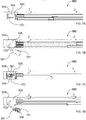
- Figures 7A-7D illustrate a cross-sectional view of the hoistway access ladder storage system 500 of the second example of this disclosure, with a horizontal cross-section taken just below a lintel of the hoistway landing doorway 502.
- Figures 7A and 7B show the hoistway access ladder storage system 500 empty
- Figures 7C and 7D show the hoistway access ladder storage system 500 with the hoistway access ladder 300 held within the rotating support 501.
- a door column 504 extends vertically below the lintel of the hoistway landing doorway 502 and has an internal cavity 505, extending vertically within the door column 504.
- the rotating support 501 is configurable between a first position (shown in Figures 7A and 7C ), in which the rotating support 501 is fully contained within the cavity 505 of the door column 504, and a second position (shown in Figures 7B and 7D ), in which the hoistway access ladder 300 is accessible from inside the landing doorway.
- Figures 7A and 7B show the hoistway access ladder storage system 500 with the hoistway access ladder 300 removed, while Figures 7C and 7D show the hoistway access ladder 300 contained within the rotating support 501.
- the rotating support 501 may be secured in the first position shown in Figures 7A and 7C using a lock (not shown), in order to prevent access to the hoistway access ladder 300 to unauthorised persons.
- the direction of rotation of the rotating support 501 between the first and second positions is indicated by arrows 703 in Figures 7B and 7D .
- the rotating support 501 can be rotated from the first position inside the cavity 505 to the second position from which the hoistway access ladder 300 can be accessed by e.g. a technician from inside a landing doorway of the hoistway.
- the rotating support 501 can be returned from the second position shown in Figures 7B and 7D , to the first position, shown in Figures 7A and 7C by rotating the rotating support 501 in the opposite direction.
- a retaining element 701 which holds the hoistway access ladder 300 in place within the rotating support 501.
- the retaining element 701 comprises a vertical extension from the base of the rotating support 501, which provides support for the base of the hoistway access ladder 300.
- the retaining element 701 may be located at one or more different points on the rotating support 501.
- the retaining element 701 may comprise a bar located at a position approximately at the midpoint of the vertical height of the rotating support 501.
- the retaining element 701 is made of metal, but in some examples may be plastic.
- the retaining element 701 may be a strap that can be tightened, opened and closed by an operator.
- multiple retaining elements 701 may be used in combination.
- the use of the retaining element 701 can be seen in Figure 7D , which shows the hoistway access ladder storage system 500 with the rotating support 501 in the second position, and the elevator hoistway access ladder 300 secured within the rotating support 501 by the retaining element 701.
- the second example shown in Figures 5-7 provides a hoistway access ladder storage system 500 which can be used to access the hoistway access ladder 300 safely and conveniently, without requiring substantial modification to existing elevator systems beyond the installation of a rotating support 501, e.g. taking advantage of any pre-existing cavity 505 of the door column 504.
- a cavity 505 compatible with the hoistway access ladder storage system 500 shown in Figures 5-7 may already be present in existing elevator landing doorways, such a system is suitable for retrofitting.
Landscapes
- Engineering & Computer Science (AREA)
- Mechanical Engineering (AREA)
- Automation & Control Theory (AREA)
- Structural Engineering (AREA)
- Maintenance And Inspection Apparatuses For Elevators (AREA)
- Ladders (AREA)
Abstract
Description
- This disclosure generally relates to storage systems for a hoistway access ladder for an elevator system. This is achieved by storing a ladder inside a column of a hoistway landing door, or in a support mounted to a door column, to ensure the hoistway access ladder can be safely accessed by maintenance personnel from a landing regardless of the dimensions of the hoistway.
- It is known for a dedicated hoistway access ladder to be provided for use in an elevator hoistway, for example to access the elevator pit or elevator car for repairs or maintenance. In conventional approaches, the hoistway ladder apparatus is located in the elevator hoistway in a retracted position, e.g. mounted on a wall of the hoistway, from which it must be retrieved in the event that maintenance is required to be carried out. In this approach, the dimensions of the hoistway must be such that sufficient space for the hoistway access ladder is available. Additionally, when the hoistway access ladder is stored within the hoistway, maintenance personnel may be required to use other equipment, such as ropes or bars, to safely retrieve the hoistway access ladder, the requirements of which will vary depending on the size of the hoistway.
- Another storage method known from the prior art is to store the hoistway access ladder within a panel of a hoistway landing door. However, this approach is unsuitable for elevator systems employing sliding landing bay doors. Various doors may not have appropriate dimensions to allow a hoistway access ladder to be stored on or in the doors. Furthermore, the weight of a ladder and its fixings may be detrimental to proper operation of the doors.
- The present disclosure seeks to provide an alternative approach.
- According to a first aspect of this disclosure, there is provided an elevator hoistway access ladder storage system comprising a hoistway access ladder and a landing doorway, the landing doorway comprising a door column and a landing door, wherein the door column comprises a cavity, and wherein the hoistway access ladder is stored within the cavity of the door column.
- In an elevator hoistway access ladder storage system as disclosed herein, a hoistway access ladder can be stored in and safely retrieved from the cavity by an operator on the landing without risking the safety of the operator, and without the use of additional equipment such as ropes or bars.
- It is desirable for the hoistway access ladder to be securely stored within the cavity in order for it to be prevented from falling into the hoistway. Thus, in one or more examples of the present disclosure, the elevator hoistway access ladder storage system further comprises at least one restraining element arranged to hold the hoistway access ladder in the interior of the cavity.
- In one or more examples of the present disclosure, the elevator hoistway access ladder storage system further comprises a rotating support mounted to the door column to support the hoistway access ladder within the cavity. The use of such a rotating support allows the hoistway access ladder to be accessed more easily by an operator, e.g. by moving the rotating support in and out of the cavity. The Applicant has realised that such a rotating support can provide for more easy retrieval of a hoistway access ladder regardless of whether the hoistway access ladder is stored within the cavity as described above, or elsewhere in the elevator hoistway.
- According to a second aspect of this disclosure, there is provided an elevator hoistway access ladder storage system comprising a landing doorway, the landing doorway comprising a door column and a landing door, wherein the door column comprises a rotating support for storing a hoistway access ladder, the rotating support being rotatable relative to the door column.
- Thus according to this second aspect of the disclosure, a hoistway access ladder can be stored in and safely retrieved from the rotating support by an operator on the landing without risking the safety of the operator, by rotating the rotating support to a convenient position for the operator to reach the hoistway access ladder. This may avoid the need for additional equipment such as ropes or bars.
- In one or more examples according to the second aspect of the present disclosure, the door column of the elevator hoistway access ladder storage system comprises a cavity, and the rotating support is rotatable between a first position inside the cavity, and a second position inside the landing doorway. By storing the rotating support within a cavity of the door column, the amount of space taken up by the rotating support when not in use can be reduced.
- In one or more examples of the present disclosure, the rotating support of the elevator hoistway access ladder storage system comprises at least one retaining element arranged to hold a hoistway access ladder in a storage position in the rotating support during use. The use of a retaining element ensures that the hoistway access ladder remains within the rotating support when it is rotated between the first and second positions.
- In some examples, the at least one restraining element mentioned above in relation to the first aspect of the present disclosure may be replaced by the at least one retaining element of the rotating support. In other examples, the elevator hoistway access ladder storage system includes the at least one retaining element arranged to hold the hoistway access ladder in a storage position in the rotating support during use, and at least one restraining element arranged to hold the rotating support in the interior of the cavity when in the first position. Thus the rotating support may itself be held in its first position in the cavity.
- In one or more examples of the present disclosure, the landing door of the elevator hoistway access ladder storage system is a side opening door. In one or more examples of the present disclosure, the landing door of the elevator hoistway access ladder storage system is a telescopic side opening door. The use of a side opening door in the system of the present disclosure simplifies access to the hoistway access ladder that may otherwise be at least partially blocked when central opening landing doors are used.
- In one or more examples of the present disclosure, the hoistway access ladder of the elevator hoistway access ladder storage system is a foldable ladder. While the system of the present disclosure can in principle be used with many kinds of folding ladder, in one or more examples of the present disclosure, the hoistway access ladder of the elevator hoistway access ladder storage system is a foldable ladder comprising a pair of uprights connected by rungs, and the hoistway access ladder is foldable into a storage configuration by moving the uprights together.
- According to another aspect of the present disclosure, there is provided an elevator system comprising an elevator car arranged to move in an elevator hoistway, and at least one landing in the hoistway comprising a landing doorway, wherein the landing doorway comprises the elevator hoistway access ladder storage system as described in any of the previously described examples.
- In one or more examples, the landing doorway of the elevator system is situated at a lowermost landing of the elevator hoistway. In this way the hoistway access ladder storage system may be used to store an elevator hoistway access ladder for access to an elevator pit, i.e. a pit access ladder.
- In any of the examples disclosed herein where the door column comprises a cavity, it will appreciated that the cavity may pre-exist in the door column or the cavity may be formed in the door column when creating the elevator hoistway access ladder storage system. In one or more examples, the cavity extends vertically along the door column. The cavity may extend along at least 50%, 60%, 70%, 80%, or 90% of the height of the door column. In one or more examples, in addition or alternatively, the cavity is an open-sided channel, for example an open-sided channel having a width and/or depth much smaller than its length. The cavity and the hoistway access ladder (whether foldable or not) may be dimensioned to match, such that the hoistway access ladder substantially fills the cavity.
- According to another aspect of this disclosure, there is provided a method of storing a hoistway access ladder in a landing doorway of an elevator hoistway, the method comprising storing a hoistway access ladder in a cavity of a door column of a landing doorway. The Applicant has realised that at least some existing elevator systems include landing doorways comprising door columns in which there is a pre-existing cavity. The Applicant has realised that such a door column cavity can advantageously be used to store a hoistway access ladder. In order to assist with storing and retrieving the hoistway access ladder, in at least some examples a rotating support for the hoistway access ladder (e.g. as described above) is retrofitted to such a door column.
- According to yet another aspect of this disclosure, there is provided a method of storing a hoistway access ladder in a landing doorway of an elevator hoistway, the method comprising: mounting a rotating support to a door column of a landing doorway, the rotating support being rotatable relative to the door column; and storing a hoistway access ladder in the rotating support. Mounting or retrofitting a rotating support to a door column of a landing doorway may allow pre-existing elevator systems to be modified to enable safe and convenient storage of a hoistway access ladder, regardless of whether the door column includes a cavity or not. The rotating support may therefore be mounted during installation of the door column or at a later point in time.
- In one or more examples, the door column comprises a cavity, and the method further comprises mounting the rotating support to rotate between a first position within the cavity to a second position inside the landing doorway. Mounting the rotating support such that it can be positioned within a cavity of a door column reduces the amount of space required in the elevator hoistway that would otherwise be taken up by the rotating support. The Applicant has realised that at least some existing elevator systems include landing doorways comprising door columns in which there is a pre-existing cavity. The Applicant has realised that such a door column cavity can be used to conveniently position a rotating support e.g. in a hidden position within the cavity to store the hoistway access ladder out of sight. As a result, a rotating support may be mounted or retrofitted to the door column of pre-existing elevator systems, improving operator safety when retrieving the hoistway access ladder.
- In at least some examples, the rotating support is mounted to a door column of a landing doorway situated at a lowermost landing of an elevator hoistway and the hoistway access ladder is a pit access ladder. Such retrofitting methods provide a rotating support that makes it easier to store and retrieve a pit access ladder, for example for use in elevator hoistways that have a pit depth of less than 2.5 m.
- Certain examples of this disclosure will now be described with reference to the accompanying drawings, in which:
-
Figure 1 is a schematic illustration of an elevator system according to examples of the present disclosure; -
Figure 2 schematically illustrates deployment of a hoistway access ladder in the pit of an elevator hoistway in accordance with the present disclosure; -
Figures 3A and 3B schematically illustrate a hoistway access ladder suitable for use in the system of the present disclosure; -
Figures 4A-4D schematically illustrate a hoistway access ladder storage system in accordance with a first example of the present disclosure; -
Figures 5A and 5B schematically illustrate a hoistway access ladder storage system including a rotating support according to a second example of the present disclosure; -
Figure 6A-6E schematically provide further illustration of a hoistway access ladder storage system including a rotating support according to the second example of the present disclosure; and -
Figures 7A-7D schematically illustrate the operation of the rotating support of the hoistway access ladder storage system according to the second example of the present disclosure. -
Figure 1 is a perspective view of anelevator system 101 including anelevator car 103, acounterweight 105, one or moreload bearing members 107, aguide rail 109, amachine 111, aposition encoder 113, and anelevator controller 115. Theelevator car 103 andcounterweight 105 are connected to each other by theload bearing members 107. Theload bearing members 107 may be, for example, ropes, steel cables, and/or coated-steel belts. Thecounterweight 105 is configured to balance a load of theelevator car 103 and is configured to facilitate movement of theelevator car 103 concurrently and in an opposite direction with respect to thecounterweight 105 within anelevator hoistway 117 and along theguide rail 109. - The
load bearing members 107 engage themachine 111, which is part of an overhead structure of theelevator system 101. Themachine 111 is configured to control movement between theelevator car 103 and thecounterweight 105. - The
elevator controller 115 is located, as shown, in acontroller room 121 of theelevator hoistway 117 and is configured to control the operation of theelevator system 101, and particularly theelevator car 103. For example, theelevator controller 115 may provide drive signals to themachine 111 to control the acceleration, deceleration, levelling, stopping, etc. of theelevator car 103. Theelevator controller 115 may also be configured to receive position signals from theposition encoder 113. When moving up or down within theelevator hoistway 117 along theguide rail 109, theelevator car 103 may stop at one ormore landings 125 as controlled by theelevator controller 115. - The
machine 111 may include a motor or similar driving mechanism and an optional braking system. Although shown and described with a rope-based load bearing system, elevator systems that employ other methods and mechanisms of moving an elevator car within an elevator hoistway, such as hydraulics, ropeless, or any other methods, are also examples of the present disclosure.FIG. 1 is merely a nonlimiting example presented for illustrative and explanatory purposes. - At the bottom of the
elevator hoistway 117, below thelowermost landing 129, is theelevator pit 127. It is often necessary for theelevator pit 127 to be accessed by maintenance personnel in order for inspection or repairs to be carried out. In elevator systems without pit access doors at the bottom of the hoistway, the distance between thelowermost landing 129 and theelevator pit 127 may be up to 2.5 m. For theelevator pit 127 to be accessed safely from thelowermost landing 129, equipment needs to be provided to allow theelevator pit 127 to be accessed. The most common way access is provided is using an elevator hoistway access ladder, such ashoistway access ladder 200 shown inFigure 2 . -
Figure 2 shows anelevator hoistway 117, andelevator pit 127, in which ahoistway access ladder 200 is deployed. Thehoistway access ladder 200 provides access to thefloor 202 of theelevator hoistway 117 from thelowermost landing 129. During use, thehoistway access ladder 200 is secured at thelowermost landing 129 and thefloor 202 of theelevator hoistway 117 by securingmeans - Although
Figure 2 illustrates ahoistway access ladder 200 being used to provide access to anelevator pit 127 from thelowermost landing 129, it will be appreciated that thehoistway access ladder 200 could also be used at anyother landing 125 within thehoistway 117 to provide access to other areas of thehoistway 117. For example, thehoistway access ladder 200 may be used to access the roof of an elevator car (e.g.elevator car 103 ofFigure 1 ) from anyappropriate landing 125. - Many designs of hoistway access ladder are known in the prior art. In the prior art, hoistway access ladders are typically stored close to or within the hoistway, and are typically foldable or retractable in order to limit the amount of storage space required within the hoistway. The design of hoistway access ladders is therefore dependent on the storage method used.
- An exemplary
hoistway access ladder 300 suitable for use in the systems of the present disclosure is shown inFigures 3A and 3B . Thehoistway access ladder 300 comprisesuprights rungs 304, and a lockinghinge 306. Lockinghinge 306 allows the ladder to be folded between a deployed configuration (shown inFigure 3B ), and a storage configuration (shown inFigure 3A ). As can be seen inFigure 3A , in the storage configuration, theuprights uprights uprights hoistway access ladder 300 is folded out to the deployed configuration shown inFigure 3B . - When in the deployed configuration, the locking
hinge 306 holds thehoistway access ladder 300 open such that it can be safely used by maintenance personnel. When thehoistway access ladder 300 is to be stored, applying relative motion betweenuprights uprights uprights rungs 304 may be hinged or collapsible. In the example shown inFigures 3A, 3B , therungs 304 are configured to rotate relative to the uprights around apoint 308, however in other examples therungs 304 of thehoistway access ladder 300 may instead be telescopic or may be collapsible by other appropriate means. - The
hoistway access ladder 300 is required to be stored close to theelevator hoistway 117 when not in use. In prior art approaches, hoistway access ladders are typically stored within the hoistway itself, for example mounted to one of the hoistway walls. However the present Applicant has realised that storage for ahoistway access ladder 300 can advantageously be provided in a cavity provided within a door column of the doorway of alanding 125, or in a support mounted to a door column of a landing doorway, as is described further below. -
Figures 4A-4D show a hoistway accessladder storage system 400 according to a first example of the present disclosure.Figures 4A-4D each show alanding doorway 402, which may be present at thelowermost landing 129 of theelevator hoistway 117 seen inFigs. 1 and2 . -
Figures 4A and 4B show a side view of the hoistway accessladder storage system 400 as viewed from the hoistway side, i.e. the rear of thelanding doorway 402.Figures 4C and 4D show an isometric view of the rear side of the hoistway accessladder storage system 400. - The
landing doorway 402 comprises adoor column 404 and alanding door 406. In the system of the present disclosure, thelanding door 406 is a telescopic landing door, however any side opening landing door could be used. Adoor column 404 is present on at least one side of thelanding doorway 402. In this example, thedoor column 404 is part of a jamb for thelanding door 406. The Applicant has realised that thedoor column 404 can be advantageously made suitable for storing ahoistway access ladder 300, providing access to thehoistway access ladder 300 safely and conveniently, without requiring substantive modification to existing elevator systems. - In the first example shown in
Figures 4A-4D , thedoor column 404 comprises acavity 405, which has dimensions suitable for storing thehoistway access ladder 300.Figures 4A and 4C show the hoistway accessladder storage system 400 with thecavity 405 empty, whileFigures 4B and 4D show the hoistway accessladder storage system 400 with thecavity 405 containing thehoistway access ladder 300. - The
hoistway access ladder 300 may be stored in thecavity 405 of thedoor column 404 without the use of any restraining devices, however in the first example thehoistway access ladder 300 is held within thecavity 405 using a restraining element 407 (seen inFigs. 4B and 4D ), such as a strap or a locking bar. After unlocking or removing the restrainingelement 407, thehoistway access ladder 300 can simply be lifted out of thecavity 405 when it is required for use. For example, when a maintenance operation such as a pit inspection is carried out, thelanding door 406 is opened from the landing side (i.e. the front of the landing door), leaving thedoorway 402 open. Thehoistway access ladder 300 can then simply be lifted out from thecavity 405 by, e.g. a technician, by reaching through thedoorway 402 from the landing side and accessing thecavity 405 on the hoistway side. This allows thehoistway access ladder 300 to be accessed without dangerously reaching out into the hoistway, for example to retrieve an access ladder from a wall of the hoistway, as is known in the prior art. The risk to maintenance personnel in accessing thehoistway access ladder 300 is therefore reduced. - In a second example of this disclosure, shown in
Figures 5A and 5B , thehoistway access ladder 300 is stored in a different configuration, in which ease of access to the hoistway access ladder is further improved in at least some cases. -
Figures 5A and 5B show a side view of a hoistway accessladder storage system 500 according to a second example of this disclosure.Figures 5A and 5B show alanding doorway 502, as may be employed at thelowermost landing 129 of theelevator hoistway 117 shown inFigures 1 and2 , as viewed from the hoistway side, i.e. the rear of thelanding doorway 502. - As in the first example described above, the
landing doorway 502 comprises adoor column 504 and a sideopening landing door 506. Thedoor column 504 comprises acavity 505, which has dimensions suitable for storing thehoistway access ladder 300.Figure 5A shows the hoistway accessladder storage system 500 with thecavity 505 empty, whileFigure 5B shows the hoistway accessladder storage system 500 with thehoistway access ladder 300 contained within thecavity 505. - In the second example, there is a
rotating support 501 mounted to thedoor column 504 in which thehoistway access ladder 300 can be stored to provide easier retrieval of thehoistway access ladder 300. As can be seen fromFig. 5B , therotating support 501 is configured to sit entirely within thecavity 505 in a first position. Therotating support 501 is mounted to be rotatable relative to thedoor column 504 to a second position inside the landing doorway, as will be described below. In this example, therotating support 501 is mounted to at least one of the walls of the cavity 505 (i.e. an interior surface of the door column 504) by a hinge (not shown), and can rotate out from thecavity 505, through the landing doorway towards the landing. However it will be appreciated that therotating support 501 may be mounted to thedoor column 504 in any suitable way, by a hinge or otherwise. -
Figures 6A-6E show the hoistway accessladder storage system 500 according to the second example from both the landing and hoistway sides of thelanding doorway 502.Figures 6A, 6C and 6E show an isometric view of the hoistway accessladder storage system 500, as viewed from the hoistway side of thelanding doorway 502.Figures 6B and 6D show an isometric view of the hoistway accessladder storage system 500 from the landing side of thelanding doorway 502. The door column 504 (comprising thecavity 505, shown inFigure 6E ) and side openinglanding door 506 are shown in each ofFigures 6A-6E . Therotating support 501 can be seen inFigures 6A, 6C, and 6E. Figure 6A shows the hoistway accessladder storage system 500 with therotating support 501 inside thecavity 505 when it is empty, whileFigure 6C shows the hoistway accessladder storage system 500 with thehoistway access ladder 300 contained within therotating support 501 inside thecavity 505. - The rotation of
rotating support 501 is shown in more detail inFigure 6E , in which the rectangular cross section of therotating support 501, as well as its direction of rotation (from thecavity 505 on the hoistway side of thelanding doorway 502 to the landing side of the landing doorway 502) shown byarrow 508, can be clearly seen. - In this example, the
rotating support 501 takes the form of a generally U-shaped sleeve, including a back wall and a pair of side walls. The sleeve of therotating support 501 has a vertical extent to match the height of thedoor column 504. However, if thehoistway access ladder 300 is shorter than thedoor column 504 then therotating support 501 may only extend along part of thedoor column 504. The back wall and side walls together define a rectangular cross-section for therotating support 501, with an open front through which thehoistway access ladder 300 can be placed to be seated between the side walls and against the back wall. - The
rotating support 501 may be secured in place within the cavity using a lock, in order to prevent access to thehoistway access ladder 300 to unauthorised persons. When a maintenance operation such as a pit inspection is carried out, therotating support 501 may be unlocked and rotated out from thecavity 505, through thelanding doorway 502 to thelanding 125 to provide access to thehoistway access ladder 300 to e.g. a technician. - The movement of the
rotating support 501 is shown in more detail inFigures 7A-7D. Figures 7A-7D illustrate a cross-sectional view of the hoistway accessladder storage system 500 of the second example of this disclosure, with a horizontal cross-section taken just below a lintel of thehoistway landing doorway 502.Figures 7A and 7B show the hoistway accessladder storage system 500 empty, whileFigures 7C and 7D show the hoistway accessladder storage system 500 with thehoistway access ladder 300 held within therotating support 501. - As shown in
Figures 7A-7D , adoor column 504 extends vertically below the lintel of thehoistway landing doorway 502 and has aninternal cavity 505, extending vertically within thedoor column 504. Therotating support 501 is configurable between a first position (shown inFigures 7A and 7C ), in which therotating support 501 is fully contained within thecavity 505 of thedoor column 504, and a second position (shown inFigures 7B and 7D ), in which thehoistway access ladder 300 is accessible from inside the landing doorway. -
Figures 7A and 7B show the hoistway accessladder storage system 500 with thehoistway access ladder 300 removed, whileFigures 7C and 7D show thehoistway access ladder 300 contained within therotating support 501. Therotating support 501 may be secured in the first position shown inFigures 7A and 7C using a lock (not shown), in order to prevent access to thehoistway access ladder 300 to unauthorised persons. - The direction of rotation of the
rotating support 501 between the first and second positions is indicated byarrows 703 inFigures 7B and 7D . When thehoistway access ladder 300 is required for use, therotating support 501 can be rotated from the first position inside thecavity 505 to the second position from which thehoistway access ladder 300 can be accessed by e.g. a technician from inside a landing doorway of the hoistway. - When the
hoistway access ladder 300 is to be stored within a hoistway, therotating support 501 can be returned from the second position shown inFigures 7B and 7D , to the first position, shown inFigures 7A and 7C by rotating therotating support 501 in the opposite direction. - Also shown in
Figures 7A-7D is a retainingelement 701, which holds thehoistway access ladder 300 in place within therotating support 501. In the example shown, the retainingelement 701 comprises a vertical extension from the base of therotating support 501, which provides support for the base of thehoistway access ladder 300. However, in other examples the retainingelement 701 may be located at one or more different points on therotating support 501. For example, the retainingelement 701 may comprise a bar located at a position approximately at the midpoint of the vertical height of therotating support 501. Preferably the retainingelement 701 is made of metal, but in some examples may be plastic. In some examples, the retainingelement 701 may be a strap that can be tightened, opened and closed by an operator. In some examples, multiple retainingelements 701 may be used in combination. The use of the retainingelement 701 can be seen inFigure 7D , which shows the hoistway accessladder storage system 500 with therotating support 501 in the second position, and the elevatorhoistway access ladder 300 secured within therotating support 501 by the retainingelement 701. - Thus, as in the first example shown in
Figure 4 , the second example shown inFigures 5-7 provides a hoistway accessladder storage system 500 which can be used to access thehoistway access ladder 300 safely and conveniently, without requiring substantial modification to existing elevator systems beyond the installation of arotating support 501, e.g. taking advantage of anypre-existing cavity 505 of thedoor column 504. As acavity 505 compatible with the hoistway accessladder storage system 500 shown inFigures 5-7 may already be present in existing elevator landing doorways, such a system is suitable for retrofitting. - It will be appreciated by those skilled in the art that the disclosure has been illustrated by describing one or more specific examples thereof, but is not limited to these examples; many variations and modifications are possible, within the scope of the accompanying claims.
Claims (15)
- An elevator hoistway access ladder storage system (400) comprising a hoistway access ladder (300) and a landing doorway (402), the landing doorway (402) comprising a door column (404) and a landing door (406); wherein the door column (404) comprises a cavity (405); and wherein the hoistway access ladder (300) is stored within the cavity (405) of the door column (404).
- The elevator hoistway access ladder storage system (400) according to claim 1, further comprising at least one restraining element (407) arranged to hold the hoistway access ladder (300) in the interior of the cavity (405).
- The elevator hoistway access ladder storage system (400) according to any preceding claim, further comprising a rotating support (501) mounted to the door column (504) to support the hoistway access ladder (300) within the cavity (505).
- An elevator hoistway access ladder storage system (500) comprising a landing doorway (502), the landing doorway (502) comprising a door column (504) and a landing door (506); wherein the door column (504) comprises a rotating support (501) for storing a hoistway access ladder (300), the rotating support (501) being rotatable relative to the door column (504).
- The elevator hoistway access ladder storage system (500) of claim 4, wherein the door column (504) comprises a cavity (505), and wherein the rotating support (501) is rotatable between a first position inside the cavity (505), and a second position inside the landing doorway (502).
- The elevator hoistway access ladder storage system (500) of any of claims 3, 4 or 5, wherein the rotating support (501) comprises at least one retaining element (701) arranged to hold a hoistway access ladder (300) in a storage position in the rotating support (501) during use.
- The elevator hoistway access ladder storage system (400; 500) according to any preceding claim, wherein the landing door (406; 506) is a side opening door.
- The elevator hoistway access ladder storage system (400; 500) of any preceding claim, wherein the landing door (406; 506) is a telescopic side opening door.
- The elevator hoistway access ladder storage system (400; 500) of any preceding claim, wherein the hoistway access ladder (300) is a foldable ladder.
- The elevator hoistway access ladder storage system (400; 500) of claim 9, wherein the hoistway access ladder (300) comprises a pair of uprights (302a, 302b) connected by rungs (304), the hoistway access ladder (300) being foldable into a storage configuration by moving the uprights (302a, 302b) together.
- An elevator system (101) comprising an elevator car (103) arranged to move in an elevator hoistway (117), and at least one landing (125, 129) in the elevator hoistway (117) comprising a landing doorway (402; 502), wherein the landing doorway (402; 502) comprises the elevator hoistway access ladder storage system (400; 500) according to any preceding claim.
- The elevator system of claim 11, wherein the landing doorway (402; 502) is situated at a lowermost landing (129) of the elevator hoistway (117).
- A method of storing a hoistway access ladder (300) in a landing doorway of an elevator hoistway (117), the method comprising:mounting a rotating support (501) to a door column of a landing doorway (402; 502), the rotating support (501) being rotatable relative to the door column (404; 504); andstoring a hoistway access ladder (300) in the rotating support (501).
- The method of claim 13, wherein the door column (404; 504) comprises a cavity (405; 505), and comprising: mounting the rotating support (501) to rotate between a first position within the cavity (405; 505) to a second position inside the landing doorway (402; 502).
- The method of claim 13 or 14, wherein the rotating support (501) is mounted to a door column of a landing doorway (402; 502) situated at a lowermost landing (129) of an elevator hoistway (117) and the hoistway access ladder (300) is a pit access ladder.
Priority Applications (3)
| Application Number | Priority Date | Filing Date | Title |
|---|---|---|---|
| EP20305709.6A EP3929136B1 (en) | 2020-06-26 | 2020-06-26 | Hoistway access ladder storage |
| US16/951,112 US11697573B2 (en) | 2020-06-26 | 2020-11-18 | Hoistway access ladder storage |
| CN202011399506.6A CN113844971A (en) | 2020-06-26 | 2020-12-04 | Hoistway access ladder storage |
Applications Claiming Priority (1)
| Application Number | Priority Date | Filing Date | Title |
|---|---|---|---|
| EP20305709.6A EP3929136B1 (en) | 2020-06-26 | 2020-06-26 | Hoistway access ladder storage |
Publications (2)
| Publication Number | Publication Date |
|---|---|
| EP3929136A1 true EP3929136A1 (en) | 2021-12-29 |
| EP3929136B1 EP3929136B1 (en) | 2024-09-25 |
Family
ID=71614818
Family Applications (1)
| Application Number | Title | Priority Date | Filing Date |
|---|---|---|---|
| EP20305709.6A Active EP3929136B1 (en) | 2020-06-26 | 2020-06-26 | Hoistway access ladder storage |
Country Status (3)
| Country | Link |
|---|---|
| US (1) | US11697573B2 (en) |
| EP (1) | EP3929136B1 (en) |
| CN (1) | CN113844971A (en) |
Cited By (1)
| Publication number | Priority date | Publication date | Assignee | Title |
|---|---|---|---|---|
| EP4733242A1 (en) * | 2024-10-25 | 2026-04-29 | Otis Elevator Company | Elevator system with storage for mobile working platform |
Families Citing this family (1)
| Publication number | Priority date | Publication date | Assignee | Title |
|---|---|---|---|---|
| US20260091957A1 (en) * | 2024-10-02 | 2026-04-02 | Otis Elevator Company | Elevator car emergency ladder systems |
Citations (4)
| Publication number | Priority date | Publication date | Assignee | Title |
|---|---|---|---|---|
| CN203255823U (en) * | 2013-04-22 | 2013-10-30 | 宁波宏大电梯有限公司 | Fire elevator escape device |
| EP3263827A1 (en) * | 2016-06-27 | 2018-01-03 | Otis Elevator Company | Locking system for foldable ladder |
| KR200486355Y1 (en) * | 2016-08-19 | 2018-05-08 | 티센크루프엘리베이터코리아 주식회사 | Wide type jamb of elevator for keeping emergency rescue portable ladder |
| WO2019064513A1 (en) * | 2017-09-29 | 2019-04-04 | 三菱電機株式会社 | Elevator pit ladder device and elevator landing door device |
Family Cites Families (4)
| Publication number | Priority date | Publication date | Assignee | Title |
|---|---|---|---|---|
| JP2015074538A (en) * | 2013-10-09 | 2015-04-20 | 株式会社日立ビルシステム | Elevator hall door device |
| EP3088342A1 (en) * | 2015-04-30 | 2016-11-02 | Kone Corporation | Maintenance platform |
| EP3517478B1 (en) * | 2018-01-29 | 2021-05-05 | Otis Elevator Company | Elevator component access cabinet |
| KR102095231B1 (en) * | 2018-07-26 | 2020-03-31 | 현대엘리베이터주식회사 | Apparatus for keeping emergency escape ladder used in elevator |
-
2020
- 2020-06-26 EP EP20305709.6A patent/EP3929136B1/en active Active
- 2020-11-18 US US16/951,112 patent/US11697573B2/en active Active
- 2020-12-04 CN CN202011399506.6A patent/CN113844971A/en active Pending
Patent Citations (4)
| Publication number | Priority date | Publication date | Assignee | Title |
|---|---|---|---|---|
| CN203255823U (en) * | 2013-04-22 | 2013-10-30 | 宁波宏大电梯有限公司 | Fire elevator escape device |
| EP3263827A1 (en) * | 2016-06-27 | 2018-01-03 | Otis Elevator Company | Locking system for foldable ladder |
| KR200486355Y1 (en) * | 2016-08-19 | 2018-05-08 | 티센크루프엘리베이터코리아 주식회사 | Wide type jamb of elevator for keeping emergency rescue portable ladder |
| WO2019064513A1 (en) * | 2017-09-29 | 2019-04-04 | 三菱電機株式会社 | Elevator pit ladder device and elevator landing door device |
Cited By (1)
| Publication number | Priority date | Publication date | Assignee | Title |
|---|---|---|---|---|
| EP4733242A1 (en) * | 2024-10-25 | 2026-04-29 | Otis Elevator Company | Elevator system with storage for mobile working platform |
Also Published As
| Publication number | Publication date |
|---|---|
| EP3929136B1 (en) | 2024-09-25 |
| CN113844971A (en) | 2021-12-28 |
| US20210403285A1 (en) | 2021-12-30 |
| US11697573B2 (en) | 2023-07-11 |
Similar Documents
| Publication | Publication Date | Title |
|---|---|---|
| EP3319896B1 (en) | Handrail for an elevator car including a locking mechanism | |
| KR100415746B1 (en) | Controller for elevator | |
| EP3819249B1 (en) | Elevator car | |
| CN109476456B (en) | Elevator device and elevator | |
| US11697573B2 (en) | Hoistway access ladder storage | |
| KR20000038410A (en) | Elevator clutch device | |
| EP3517478B1 (en) | Elevator component access cabinet | |
| US20190100410A1 (en) | Elevator car, elevator system and method of maintaining an elevator system | |
| RU98105416A (en) | METHOD FOR UNLOADING STOCKS OF SHEETS AND DEVICE FOR UNLOADING STOCK OF SHEETS | |
| EP3604197B1 (en) | Elevator car | |
| KR20200021109A (en) | Apparatus for keeping emergency escape ladder used in elevator | |
| JP4454765B2 (en) | elevator | |
| KR20210023098A (en) | scaffold System | |
| EP3659958B1 (en) | Column-integrated step for elevator systems | |
| CN112047221B (en) | An elevator with an emergency rescue channel structure | |
| EP4691956A1 (en) | Elevator system and methods of installing and deinstalling a mobile working platform in such elevator system | |
| JP3807851B2 (en) | Elevator hoistway | |
| EP3800157B1 (en) | Elevator apron | |
| CN112960522A (en) | Elevator landing door system | |
| US20260091957A1 (en) | Elevator car emergency ladder systems | |
| JP2025148842A (en) | Cars and elevators | |
| EP4735371A1 (en) | Apron device, elevator car and method for protecting from falling into elevator shaft | |
| TW202600443A (en) | Machine maintenance lifting device | |
| WO2026078860A1 (en) | Elevator door device and elevator | |
| JP2002205881A (en) | Elevator equipment |
Legal Events
| Date | Code | Title | Description |
|---|---|---|---|
| PUAI | Public reference made under article 153(3) epc to a published international application that has entered the european phase |
Free format text: ORIGINAL CODE: 0009012 |
|
| STAA | Information on the status of an ep patent application or granted ep patent |
Free format text: STATUS: THE APPLICATION HAS BEEN PUBLISHED |
|
| AK | Designated contracting states |
Kind code of ref document: A1 Designated state(s): AL AT BE BG CH CY CZ DE DK EE ES FI FR GB GR HR HU IE IS IT LI LT LU LV MC MK MT NL NO PL PT RO RS SE SI SK SM TR |
|
| B565 | Issuance of search results under rule 164(2) epc |
Effective date: 20210112 |
|
| STAA | Information on the status of an ep patent application or granted ep patent |
Free format text: STATUS: REQUEST FOR EXAMINATION WAS MADE |
|
| 17P | Request for examination filed |
Effective date: 20220223 |
|
| RBV | Designated contracting states (corrected) |
Designated state(s): AL AT BE BG CH CY CZ DE DK EE ES FI FR GB GR HR HU IE IS IT LI LT LU LV MC MK MT NL NO PL PT RO RS SE SI SK SM TR |
|
| GRAP | Despatch of communication of intention to grant a patent |
Free format text: ORIGINAL CODE: EPIDOSNIGR1 |
|
| STAA | Information on the status of an ep patent application or granted ep patent |
Free format text: STATUS: GRANT OF PATENT IS INTENDED |
|
| INTG | Intention to grant announced |
Effective date: 20240419 |
|
| GRAS | Grant fee paid |
Free format text: ORIGINAL CODE: EPIDOSNIGR3 |
|
| GRAA | (expected) grant |
Free format text: ORIGINAL CODE: 0009210 |
|
| STAA | Information on the status of an ep patent application or granted ep patent |
Free format text: STATUS: THE PATENT HAS BEEN GRANTED |
|
| AK | Designated contracting states |
Kind code of ref document: B1 Designated state(s): AL AT BE BG CH CY CZ DE DK EE ES FI FR GB GR HR HU IE IS IT LI LT LU LV MC MK MT NL NO PL PT RO RS SE SI SK SM TR |
|
| REG | Reference to a national code |
Ref country code: GB Ref legal event code: FG4D |
|
| REG | Reference to a national code |
Ref country code: CH Ref legal event code: EP |
|
| REG | Reference to a national code |
Ref country code: DE Ref legal event code: R096 Ref document number: 602020038242 Country of ref document: DE |
|
| REG | Reference to a national code |
Ref country code: IE Ref legal event code: FG4D |
|
| REG | Reference to a national code |
Ref country code: LT Ref legal event code: MG9D |
|
| PG25 | Lapsed in a contracting state [announced via postgrant information from national office to epo] |
Ref country code: NO Free format text: LAPSE BECAUSE OF FAILURE TO SUBMIT A TRANSLATION OF THE DESCRIPTION OR TO PAY THE FEE WITHIN THE PRESCRIBED TIME-LIMIT Effective date: 20241225 |
|
| PG25 | Lapsed in a contracting state [announced via postgrant information from national office to epo] |
Ref country code: GR Free format text: LAPSE BECAUSE OF FAILURE TO SUBMIT A TRANSLATION OF THE DESCRIPTION OR TO PAY THE FEE WITHIN THE PRESCRIBED TIME-LIMIT Effective date: 20241226 Ref country code: FI Free format text: LAPSE BECAUSE OF FAILURE TO SUBMIT A TRANSLATION OF THE DESCRIPTION OR TO PAY THE FEE WITHIN THE PRESCRIBED TIME-LIMIT Effective date: 20240925 |
|
| PG25 | Lapsed in a contracting state [announced via postgrant information from national office to epo] |
Ref country code: BG Free format text: LAPSE BECAUSE OF FAILURE TO SUBMIT A TRANSLATION OF THE DESCRIPTION OR TO PAY THE FEE WITHIN THE PRESCRIBED TIME-LIMIT Effective date: 20240925 |
|
| PG25 | Lapsed in a contracting state [announced via postgrant information from national office to epo] |
Ref country code: LV Free format text: LAPSE BECAUSE OF FAILURE TO SUBMIT A TRANSLATION OF THE DESCRIPTION OR TO PAY THE FEE WITHIN THE PRESCRIBED TIME-LIMIT Effective date: 20240925 |
|
| PG25 | Lapsed in a contracting state [announced via postgrant information from national office to epo] |
Ref country code: RS Free format text: LAPSE BECAUSE OF FAILURE TO SUBMIT A TRANSLATION OF THE DESCRIPTION OR TO PAY THE FEE WITHIN THE PRESCRIBED TIME-LIMIT Effective date: 20241225 |
|
| REG | Reference to a national code |
Ref country code: NL Ref legal event code: MP Effective date: 20240925 |
|
| PG25 | Lapsed in a contracting state [announced via postgrant information from national office to epo] |
Ref country code: RS Free format text: LAPSE BECAUSE OF FAILURE TO SUBMIT A TRANSLATION OF THE DESCRIPTION OR TO PAY THE FEE WITHIN THE PRESCRIBED TIME-LIMIT Effective date: 20241225 Ref country code: NO Free format text: LAPSE BECAUSE OF FAILURE TO SUBMIT A TRANSLATION OF THE DESCRIPTION OR TO PAY THE FEE WITHIN THE PRESCRIBED TIME-LIMIT Effective date: 20241225 Ref country code: LV Free format text: LAPSE BECAUSE OF FAILURE TO SUBMIT A TRANSLATION OF THE DESCRIPTION OR TO PAY THE FEE WITHIN THE PRESCRIBED TIME-LIMIT Effective date: 20240925 Ref country code: GR Free format text: LAPSE BECAUSE OF FAILURE TO SUBMIT A TRANSLATION OF THE DESCRIPTION OR TO PAY THE FEE WITHIN THE PRESCRIBED TIME-LIMIT Effective date: 20241226 Ref country code: FI Free format text: LAPSE BECAUSE OF FAILURE TO SUBMIT A TRANSLATION OF THE DESCRIPTION OR TO PAY THE FEE WITHIN THE PRESCRIBED TIME-LIMIT Effective date: 20240925 Ref country code: BG Free format text: LAPSE BECAUSE OF FAILURE TO SUBMIT A TRANSLATION OF THE DESCRIPTION OR TO PAY THE FEE WITHIN THE PRESCRIBED TIME-LIMIT Effective date: 20240925 |
|
| REG | Reference to a national code |
Ref country code: AT Ref legal event code: MK05 Ref document number: 1726521 Country of ref document: AT Kind code of ref document: T Effective date: 20240925 |
|
| PG25 | Lapsed in a contracting state [announced via postgrant information from national office to epo] |
Ref country code: NL Free format text: LAPSE BECAUSE OF FAILURE TO SUBMIT A TRANSLATION OF THE DESCRIPTION OR TO PAY THE FEE WITHIN THE PRESCRIBED TIME-LIMIT Effective date: 20240925 |
|
| PG25 | Lapsed in a contracting state [announced via postgrant information from national office to epo] |
Ref country code: PT Free format text: LAPSE BECAUSE OF FAILURE TO SUBMIT A TRANSLATION OF THE DESCRIPTION OR TO PAY THE FEE WITHIN THE PRESCRIBED TIME-LIMIT Effective date: 20250127 Ref country code: IS Free format text: LAPSE BECAUSE OF FAILURE TO SUBMIT A TRANSLATION OF THE DESCRIPTION OR TO PAY THE FEE WITHIN THE PRESCRIBED TIME-LIMIT Effective date: 20250125 |
|
| PG25 | Lapsed in a contracting state [announced via postgrant information from national office to epo] |
Ref country code: RO Free format text: LAPSE BECAUSE OF FAILURE TO SUBMIT A TRANSLATION OF THE DESCRIPTION OR TO PAY THE FEE WITHIN THE PRESCRIBED TIME-LIMIT Effective date: 20240925 Ref country code: SM Free format text: LAPSE BECAUSE OF FAILURE TO SUBMIT A TRANSLATION OF THE DESCRIPTION OR TO PAY THE FEE WITHIN THE PRESCRIBED TIME-LIMIT Effective date: 20240925 |
|
| PG25 | Lapsed in a contracting state [announced via postgrant information from national office to epo] |
Ref country code: ES Free format text: LAPSE BECAUSE OF FAILURE TO SUBMIT A TRANSLATION OF THE DESCRIPTION OR TO PAY THE FEE WITHIN THE PRESCRIBED TIME-LIMIT Effective date: 20240925 |
|
| PG25 | Lapsed in a contracting state [announced via postgrant information from national office to epo] |
Ref country code: EE Free format text: LAPSE BECAUSE OF FAILURE TO SUBMIT A TRANSLATION OF THE DESCRIPTION OR TO PAY THE FEE WITHIN THE PRESCRIBED TIME-LIMIT Effective date: 20240925 Ref country code: AT Free format text: LAPSE BECAUSE OF FAILURE TO SUBMIT A TRANSLATION OF THE DESCRIPTION OR TO PAY THE FEE WITHIN THE PRESCRIBED TIME-LIMIT Effective date: 20240925 |
|
| PG25 | Lapsed in a contracting state [announced via postgrant information from national office to epo] |
Ref country code: CZ Free format text: LAPSE BECAUSE OF FAILURE TO SUBMIT A TRANSLATION OF THE DESCRIPTION OR TO PAY THE FEE WITHIN THE PRESCRIBED TIME-LIMIT Effective date: 20240925 Ref country code: PL Free format text: LAPSE BECAUSE OF FAILURE TO SUBMIT A TRANSLATION OF THE DESCRIPTION OR TO PAY THE FEE WITHIN THE PRESCRIBED TIME-LIMIT Effective date: 20240925 |
|
| PG25 | Lapsed in a contracting state [announced via postgrant information from national office to epo] |
Ref country code: IT Free format text: LAPSE BECAUSE OF FAILURE TO SUBMIT A TRANSLATION OF THE DESCRIPTION OR TO PAY THE FEE WITHIN THE PRESCRIBED TIME-LIMIT Effective date: 20240925 Ref country code: SK Free format text: LAPSE BECAUSE OF FAILURE TO SUBMIT A TRANSLATION OF THE DESCRIPTION OR TO PAY THE FEE WITHIN THE PRESCRIBED TIME-LIMIT Effective date: 20240925 |
|
| REG | Reference to a national code |
Ref country code: DE Ref legal event code: R097 Ref document number: 602020038242 Country of ref document: DE |
|
| PGFP | Annual fee paid to national office [announced via postgrant information from national office to epo] |
Ref country code: DE Payment date: 20250520 Year of fee payment: 6 |
|
| PG25 | Lapsed in a contracting state [announced via postgrant information from national office to epo] |
Ref country code: DK Free format text: LAPSE BECAUSE OF FAILURE TO SUBMIT A TRANSLATION OF THE DESCRIPTION OR TO PAY THE FEE WITHIN THE PRESCRIBED TIME-LIMIT Effective date: 20240925 |
|
| PGFP | Annual fee paid to national office [announced via postgrant information from national office to epo] |
Ref country code: FR Payment date: 20250521 Year of fee payment: 6 |
|
| PLBE | No opposition filed within time limit |
Free format text: ORIGINAL CODE: 0009261 |
|
| STAA | Information on the status of an ep patent application or granted ep patent |
Free format text: STATUS: NO OPPOSITION FILED WITHIN TIME LIMIT |
|
| 26N | No opposition filed |
Effective date: 20250626 |
|
| PG25 | Lapsed in a contracting state [announced via postgrant information from national office to epo] |
Ref country code: SE Free format text: LAPSE BECAUSE OF FAILURE TO SUBMIT A TRANSLATION OF THE DESCRIPTION OR TO PAY THE FEE WITHIN THE PRESCRIBED TIME-LIMIT Effective date: 20240925 |
|
| PG25 | Lapsed in a contracting state [announced via postgrant information from national office to epo] |
Ref country code: HR Free format text: LAPSE BECAUSE OF FAILURE TO SUBMIT A TRANSLATION OF THE DESCRIPTION OR TO PAY THE FEE WITHIN THE PRESCRIBED TIME-LIMIT Effective date: 20240925 |
|
| REG | Reference to a national code |
Ref country code: CH Ref legal event code: H13 Free format text: ST27 STATUS EVENT CODE: U-0-0-H10-H13 (AS PROVIDED BY THE NATIONAL OFFICE) Effective date: 20260127 |
|
| PG25 | Lapsed in a contracting state [announced via postgrant information from national office to epo] |
Ref country code: MC Free format text: LAPSE BECAUSE OF FAILURE TO SUBMIT A TRANSLATION OF THE DESCRIPTION OR TO PAY THE FEE WITHIN THE PRESCRIBED TIME-LIMIT Effective date: 20240925 |
|
| PG25 | Lapsed in a contracting state [announced via postgrant information from national office to epo] |
Ref country code: LU Free format text: LAPSE BECAUSE OF NON-PAYMENT OF DUE FEES Effective date: 20250626 |
|
| GBPC | Gb: european patent ceased through non-payment of renewal fee |
Effective date: 20250626 |
|
| REG | Reference to a national code |
Ref country code: BE Ref legal event code: MM Effective date: 20250630 |
|
| PG25 | Lapsed in a contracting state [announced via postgrant information from national office to epo] |
Ref country code: GB Free format text: LAPSE BECAUSE OF NON-PAYMENT OF DUE FEES Effective date: 20250626 |
|
| PG25 | Lapsed in a contracting state [announced via postgrant information from national office to epo] |
Ref country code: IE Free format text: LAPSE BECAUSE OF NON-PAYMENT OF DUE FEES Effective date: 20250626 |
|
| PG25 | Lapsed in a contracting state [announced via postgrant information from national office to epo] |
Ref country code: BE Free format text: LAPSE BECAUSE OF NON-PAYMENT OF DUE FEES Effective date: 20250630 |
|
| PG25 | Lapsed in a contracting state [announced via postgrant information from national office to epo] |
Ref country code: CH Free format text: LAPSE BECAUSE OF NON-PAYMENT OF DUE FEES Effective date: 20250630 |