EP3929102A1 - A device for connecting a packaging container to an associated closure - Google Patents
A device for connecting a packaging container to an associated closure Download PDFInfo
- Publication number
- EP3929102A1 EP3929102A1 EP20182527.0A EP20182527A EP3929102A1 EP 3929102 A1 EP3929102 A1 EP 3929102A1 EP 20182527 A EP20182527 A EP 20182527A EP 3929102 A1 EP3929102 A1 EP 3929102A1
- Authority
- EP
- European Patent Office
- Prior art keywords
- closure
- packaging container
- elongated element
- length
- attached
- Prior art date
- Legal status (The legal status is an assumption and is not a legal conclusion. Google has not performed a legal analysis and makes no representation as to the accuracy of the status listed.)
- Withdrawn
Links
- 238000004806 packaging method and process Methods 0.000 title claims abstract description 73
- 239000000853 adhesive Substances 0.000 claims description 10
- 230000001070 adhesive effect Effects 0.000 claims description 10
- 235000013361 beverage Nutrition 0.000 description 8
- 239000000463 material Substances 0.000 description 7
- 238000004519 manufacturing process Methods 0.000 description 4
- 230000002349 favourable effect Effects 0.000 description 3
- 238000000034 method Methods 0.000 description 3
- 239000013502 plastic waste Substances 0.000 description 3
- 235000021056 liquid food Nutrition 0.000 description 2
- 238000000465 moulding Methods 0.000 description 2
- 230000002411 adverse Effects 0.000 description 1
- 238000005452 bending Methods 0.000 description 1
- 238000006073 displacement reaction Methods 0.000 description 1
- 239000002699 waste material Substances 0.000 description 1
Images


Classifications
-
- B—PERFORMING OPERATIONS; TRANSPORTING
- B65—CONVEYING; PACKING; STORING; HANDLING THIN OR FILAMENTARY MATERIAL
- B65D—CONTAINERS FOR STORAGE OR TRANSPORT OF ARTICLES OR MATERIALS, e.g. BAGS, BARRELS, BOTTLES, BOXES, CANS, CARTONS, CRATES, DRUMS, JARS, TANKS, HOPPERS, FORWARDING CONTAINERS; ACCESSORIES, CLOSURES, OR FITTINGS THEREFOR; PACKAGING ELEMENTS; PACKAGES
- B65D55/00—Accessories for container closures not otherwise provided for
- B65D55/16—Devices preventing loss of removable closure members
Definitions
- the invention relates to a device for connecting a top portion of a packaging container to a closure, such as a cap.
- the invention also relates to a package as well as to a closure comprising such a device.
- a common source of human-derived waste in nature is plastic caps coming from beverage containers.
- Conventional single-use beverage containers normally include a cap which is screwed onto the beverage container. When unscrewing the cap, it is easily dropped on the ground and potentially lost, thereby contributing to the spread of plastic debris in nature.
- a device for connecting a packaging container to an associated closure.
- the device comprises an elongated element having a first end attachable to the packaging container and a second end attachable to the closure.
- the elongated element is configured to allow removal of the closure from the packaging container without breaking, when the device is attached to the packaging container and to the closure.
- the elongated element is extendable, which is favorable in that it can withstand for instance rotational movements or bending forces without breaking, as well as being capable of adapting to an increased length required for unscrewing the closure from the packaging container.
- the elongated element may be configured as having one predetermined and well-defined first length when the closure is connected to the packaging container, and a second well-defined length that is available when the closure is unscrewed from the packaging container.
- the elongated element is stretchable, which is favorable in that the device can adapt to any feasible length that is required for unscrewing the closure from the packaging container.
- the elongated element may be subject to an initial (and partial) stretch when the closure is initially unscrewed. However, if the unscrewing process is aborted, the elongated element will not have reached its maximum stretched length which will facilitate handling of the device.
- the second end of the elongated element is attachable to the closure via a rotary joint.
- the elongated element may have a fixed length that does not change during unscrewing of the closure from the packaging container.
- the elongated element is attached to the packaging container and/or the closure by means of an adhesive.
- the device can be attached to the packaging container and closure after production of the packaging containers, thereby allowing the use of the device for existing production lines.
- the elongated element is transformable from an idle configuration, in which the elongated element has a first length, to an extended configuration, in which the elongated element has a second length being greater than the first length.
- the device further comprises a decor layer arranged on an outer side of the elongated element.
- the decor layer may be broken upon opening of a package comprising the packaging container and the closure. This is favorable since the need for a separate tamper-ring on the closure may be eliminated, thereby reducing the amount of material used in the process of developing the closure.
- a package comprising a packaging container and a device as described above, wherein the first end of the elongated element is attached to the packaging container.
- a closure for use with a packaging container, comprising a device as described above, wherein the second end of the elongated element is attached to the closure.
- FIG. 1a illustrates the package 1 comprising a packaging container 20 and a closure 30, or cap, associated thereto.
- a device 10 is connected to the packaging container 20 at a first end 12, and connected to the closure 30 at a second, opposite, end 13.
- the package 1 is shown in a closed position, i.e. the closure 30 is closing the upper end/spout of the packaging container 20. Details regarding these elements and their interrelatedness will be further described below.
- Fig. 1b the same package 1 of Fig. 1a is illustrated as seen from above.
- the packaging container 20 and closure 30 have a circular cross-section.
- the shape of the packaging container 20 and closure 30 is schematically illustrated and not limited to this exact geometry.
- the cross-section may be rectangular, triangular, or have any other suitable shape.
- the device 10 is shown as having a rectangular strip-like configuration, which is also merely an exemplifying geometrical shape. The features of the device 10 will be further elucidated below especially with respect to Figs. 3a-c .
- the package 1 is shown in open positions in Figs. 1c-d , which means that the closure 30 has been removed from the spout 21 of the packaging container 20 thereby allowing content, preferably liquid food, to be poured out from the packaging container 20.
- This open position can hence also be regarded as a position of use.
- the device 10 is connected to the packaging container 20 at its first end 12 and to the closure 30 at its second end 13. More specifically, the second end 13 of the device 10 is connected to an outer surface 32 of the closure 30.
- the closure 30 is preferably provided with internal threads 31 configured to engage with a threaded spout 21 of the associated packaging container 20. The internal threads 31 of the closure 30 and the threaded spout 21 of the packaging member 20 are engaged with each other when the package 1 is in a closed position (understood implicitly in Fig. 1a ).
- the device 10 is connected to the packaging container 20 remote from the spout 21. In all figures displaying the device 10, the first end 12 of the device 10 is connected to the packaging container 20 on a top portion thereof, remote from the spout 21. However, the first end 12 of the device 10 may be connected elsewhere on the packaging container 20.
- Fig. 1c the length of the device 10 is unchanged as compared to the position of the device 10 as shown in Fig. 1a , where the package 1 is in a closed position.
- Fig. 1d the device 10 is extended to almost three times the length of the device 10 as seen in Fig. 1a .
- the configurations allowing for such extension will be explained further below.
- Embodiments of the closure 30, including the device 10, are illustrated in Figs. 2a-b .
- Both Figs. 2ab share the general structure of the closure 30 with internal threads 31 configured to engage with a threaded spout 21 of an associated packaging container 20 (not shown).
- the first end 12 of the device 10 is attachable to a packaging container 20.
- the second end 13 of the device 10 is attached to the outer surface 32 of the closure 30 via a rotary joint 40.
- This rotary joint 40 is rotatable about a vertical axis (not shown), assuming the closure 30 is arranged on an up-right standing packaging container 20.
- the rotary joint 40 is for example comprising a bottom portion 41 attached to the closure 30 by means of an adhesive 15, and a top portion 42 fixedly coupled to the bottom portion 41 on an upper end thereof, however leaving an axial gap between the bottom portion 41 and the top portion 42.
- the second end 13 of the device 10 is provided with a circular hole, thus forming a ring-shape.
- the second end 13 is arranged axially in between the bottom portion 41 and the top portion 42.
- the purpose of the top portion 42 is to prohibit the device 10 from disconnecting its second end 13 from the closure 30, thereby forming an axial stop.
- the top portion 42 fulfills its purpose, it can come in any shape. It could for instance be shaped as a disc-like member having an axial pin connecting to the bottom portion 41, a knob, or the like.
- the bottom portion 41 may consequently be provided with a central recess.
- the second end 13 of the device 10 is positioned onto the bottom portion 41, such that the ring shape of the second end 13 is aligned with the central recess of the bottom portion 41.
- the top portion 42 is thereby attached to the bottom portion 41 by e.g. snap-locking a pin (or similar structure) into the central recess of the bottom portion 41.
- the second end 13 of the device 10 is thereby axially locked, while the ring-shape at the same time prevents radial displacement of the second end 13 relative the bottom portion 41 and the top portion 42. As the second end 13 is allowed to rotate, the rotary joint 40 is formed.
- the device 10 has substantially the same length L1 prior to, during and after opening of the package 1, i.e. after removal of the closure 30 from the packaging container 20. Moreover, the device 10 remains attached to both the closure 30 and the packaging container 20 prior to, during and after opening of the package 1.
- the second end 13 of the device 10 is fixedly attached to the outer surface 32 of the closure 30 by means of an adhesive 15 without a rotary joint 40.
- the device 10 is transformable from an idle configuration, in which it has a first length L1, to an extended configuration, in which it has a second length L2 being greater than the first length L1.
- the device 10 comprises an elongated element 11 (see Figs. 3b and 3c ) which e.g. is folded in the idle configuration, and unfolded in the extended configuration.
- the elongated element 11 is formed by a stretchable material allowing for the length to be extended.
- the elongated element 11 of the device 10 When extended, the elongated element 11 of the device 10 may be arranged in a zigzag pattern.
- the transformability of the device 10 of Fig. 2b achieves a similar goal as the rotary joint 40 of Fig. 2a , namely to keep the device 10 attached to the closure 30 and the packaging container 20 during a position of use.
- the device 10 remains attached to both the closure 30 and to the packaging container 20 prior to, during and after opening of the package 1.
- the device 10 is further described with respect to Figs. 3a-c .
- the device 10 is configured to connect a packaging container 20 to an associated closure 30.
- the device 10 constitutes a link configured to hold a packaging container 20 and its closure 30 together when the closure 30 is unscrewed from the packaging container 20.
- the device 10 can also be regarded as a sigil that allows an unscrewing of the closure 30, or cap, from a packaging container 20 without breaking the sigil, thereby keeping the closure 30 attached, or tethered, to the packaging container 20. This tethering of the closure 30 to the packaging container 20 prevents the closure 30 from being lost when the package 1 is opened, which solves the problem mentioned above.
- the device 10 as shown in Figs. 3a-c has an elongated element 11 with a first end 12 attachable to a packaging container 20 and a second end 13 attachable to a closure 30.
- the elongated element 11, which may be extendable for example by stretching, is configured to allow removal of the closure 30 from the packaging container 20 without breaking when the device 10 is attached to the packaging container 20 and to the closure 30.
- the closure 30 is screwably mountable to the packaging member 20
- the elongated element 11 is configured to withstand the rotational movement of unscrewing the closure 30 from the packaging member 20.
- the device 10 as shown in Fig. 3a corresponds to the device shown in the embodiment of Fig. 2a .
- the device has an elongated element 11 which preferably has a fixed length L1 which is substantially the same before, during and after use, i.e. opening of a package 1.
- a decor layer 14 is arranged which may have a print, marking or the like.
- the decor layer 14 is attached to the extendable element 11 by means of an adhesive.
- the second end 13 is provided with a hole 13b for allowing the rotary joint 40 to be formed.
- the device 10 as shown in Fig. 3b corresponds to the device shown in the embodiment of Fig. 2b .
- the device 10 has an elongated element 11 which is extendable by unfolding, and is transformable from an idle configuration, in which the elongated element 11 has a first length L1 as shown in Fig. 3a , to an extended configuration, in which the elongated element 11 has a second length L2 being greater than the first length L1 (see Fig. 3c ).
- the second length L2 may be at least two times the first length L1; however the exact relationship between L1 and L2 depends on the extra length required to unscrew the closure 30 from the packaging container 20 without causing the elongated element 11 to break.
- the elongated element 11 is folded in the idle configuration, and unfolded in the extended configuration, and the second length L2 depends on the number of folds in the idle configuration. For example, if the elongated element 11 is folded twice, the second length L2 will be around three times the first length L1 if the folds are arranged at the respective ends of the elongated element 11.
- the elongated element 11 may be fixed in the folded configuration, e.g. by providing small quantities of adhesives between the folds which will break, thereby allowing unfolding, when the closure 30 is unscrewed thereby applying a pulling/shear force on the device 10.
- the elongated element 11 is formed by molding a plastic material, wherein the folds are joined by a minor quantity of plastic material during the molding process. Also in this case the joints between the folds will break when it is required to extend the length of the device 10.
- a decor layer 14 is arranged on an outer side of the elongated element 11 shown in Fig. 3b .
- the decor layer 14 may have a print or marking.
- the decor layer 14 is attached to the extendable element 11 by means of an adhesive.
- the elongated element 11 is attached to the packaging container 20 and/or the closure 30 by means of an adhesive 15, where the first end 12 is attached to the packaging container 20 by means of a first portion of adhesive 15 and the second end 13 is attached to the closure 30 by means of a second portion of adhesive 15.
- the elongated element 11 is in its extended configuration. When extended, the elongated element 11 is arranged in a substantially zigzag pattern due to the configuration of the folds. Once extended, the elongated element 11 has a second length L2.
- the dashed rectangular areas in Fig. 3c show the decor layer 14 in two pieces, where the decor layer has been broken when the closure 30 has been removed from the packaging container 20. This may be useful for instance, in case the package 1 is configured to hold a beverage or other liquid food product, to indicate if the package 1 has been opened or not.
- the elongated element 11 may be regarded as a slitted element.
- the elongated element 11 is formed by a stretchable material, preferably a stretchable plastic material.
- the closure 30 is unscrewed from the packaging container 20 the elongated element 11 will extend in length due to the pulling/shear force applied to the device 10.
- the provision of folds may be omitted.
- the embodiments described above i.e. the device 10 being attached by means of a rotary joint 40 wherein the elongated element 11 has a fixed length, the elongated element 11 being extendable by means of unfolding, and the elongated element being extendable by stretching, could be combined in any suitable configuration to provide for a device 10, or sigil, allowing the closure 30 to be connected to the associated packaging container 20 also when the closure 30 is removed from the spout of the packaging container 20.
Landscapes
- Engineering & Computer Science (AREA)
- Mechanical Engineering (AREA)
- Cartons (AREA)
Abstract
A device (10) for connecting a packaging container (20) to an associated closure (30), comprising an elongated element (11) having a first end (12) attachable to the packaging container (20) and a second end (13) attachable to the closure (30), wherein the elongated element (11) is configured to allow removal of the closure (30) from the packaging container (20) without breaking when the device (10) is attached to the packaging container (20) and to the closure (30).
Description
- The invention relates to a device for connecting a top portion of a packaging container to a closure, such as a cap. The invention also relates to a package as well as to a closure comprising such a device.
- Plastic pollution has become a hot topic over the past few years, with increased interest and knowledge in how plastic waste adversely affects the environment on different levels. A common source of human-derived waste in nature is plastic caps coming from beverage containers. Conventional single-use beverage containers normally include a cap which is screwed onto the beverage container. When unscrewing the cap, it is easily dropped on the ground and potentially lost, thereby contributing to the spread of plastic debris in nature.
- As a consequence, the European Union has issued a new Directive on the reduction of the impact of certain plastic products on the environment, such as caps and lids used for single-use plastic beverage containers. In the future, manufacturers of beverage containers must take measures to reduce the risk for plastic waste to appear in nature, especially in the case of plastic caps.
- To meet this new product requirement, there is a need for an improved solution for caps or lids to beverage containers which can help in reducing plastic waste in the environment, preferably without requiring major changes to already installed cap production lines.
- It is an object of the invention to at least partly overcome one or more of the above-identified limitations of the prior art. In particular, it is an object to reduce the amount of plastic closures of beverage containers ending up in the environment.
- According to a first aspect, a device is provided for connecting a packaging container to an associated closure. The device comprises an elongated element having a first end attachable to the packaging container and a second end attachable to the closure. The elongated element is configured to allow removal of the closure from the packaging container without breaking, when the device is attached to the packaging container and to the closure. An advantage of having this device connected to both the packaging container and the closure is that plastic pollution in the environment can be reduced since the closure will not be lost when a package comprising the packaging container and the closure is opened. Additionally, the device is provided without making any substantial changes to existing cap production lines.
- According to an embodiment, the elongated element is extendable, which is favorable in that it can withstand for instance rotational movements or bending forces without breaking, as well as being capable of adapting to an increased length required for unscrewing the closure from the packaging container. Yet further, the elongated element may be configured as having one predetermined and well-defined first length when the closure is connected to the packaging container, and a second well-defined length that is available when the closure is unscrewed from the packaging container.
- According to another embodiment, the elongated element is stretchable, which is favorable in that the device can adapt to any feasible length that is required for unscrewing the closure from the packaging container. For example, the elongated element may be subject to an initial (and partial) stretch when the closure is initially unscrewed. However, if the unscrewing process is aborted, the elongated element will not have reached its maximum stretched length which will facilitate handling of the device.
- According to yet another embodiment, the second end of the elongated element is attachable to the closure via a rotary joint. For such embodiment the elongated element may have a fixed length that does not change during unscrewing of the closure from the packaging container.
- According to another embodiment, the elongated element is attached to the packaging container and/or the closure by means of an adhesive. This is advantageous in that the device can be attached to the packaging container and closure after production of the packaging containers, thereby allowing the use of the device for existing production lines.
- According to an embodiment, the elongated element is transformable from an idle configuration, in which the elongated element has a first length, to an extended configuration, in which the elongated element has a second length being greater than the first length.
- According to yet another embodiment, the device further comprises a decor layer arranged on an outer side of the elongated element. Optionally, the decor layer may be broken upon opening of a package comprising the packaging container and the closure. This is favorable since the need for a separate tamper-ring on the closure may be eliminated, thereby reducing the amount of material used in the process of developing the closure.
- According to a second aspect, a package is provided, comprising a packaging container and a device as described above, wherein the first end of the elongated element is attached to the packaging container.
- According to a third aspect, a closure is provided for use with a packaging container, comprising a device as described above, wherein the second end of the elongated element is attached to the closure.
- Still other objectives, features, aspects and advantages of the invention will appear from the following detailed description as well as from the drawings.
- Embodiments of the invention will now be described, by way of example, with reference to the accompanying schematic drawings, in which
-
Fig. 1a is a side view of a closed package, -
Fig. 1b is a top view of the package shown inFig. 1a , -
Figs. 1c-d are side views of an open package provided with a device according to various embodiments, -
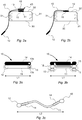
Figs. 2a-b are side views of two embodiments of a closure with a device, -
Figs. 3a-b are exploded top views of two devices with elongated elements in an idle configuration, and -
Fig. 3c is a top view of the elongated element ofFig. 3b in an extended configuration. - A
package 1 according to two different embodiments of the invention are shown inFigs. 1a-d .Fig. 1a illustrates thepackage 1 comprising apackaging container 20 and aclosure 30, or cap, associated thereto. Adevice 10 is connected to thepackaging container 20 at afirst end 12, and connected to theclosure 30 at a second, opposite,end 13. Here, thepackage 1 is shown in a closed position, i.e. theclosure 30 is closing the upper end/spout of thepackaging container 20. Details regarding these elements and their interrelatedness will be further described below. - In
Fig. 1b , thesame package 1 ofFig. 1a is illustrated as seen from above. As illustrated, thepackaging container 20 andclosure 30 have a circular cross-section. It should be noted that the shape of thepackaging container 20 andclosure 30 is schematically illustrated and not limited to this exact geometry. For instance, the cross-section may be rectangular, triangular, or have any other suitable shape. Similarly, thedevice 10 is shown as having a rectangular strip-like configuration, which is also merely an exemplifying geometrical shape. The features of thedevice 10 will be further elucidated below especially with respect toFigs. 3a-c . - The
package 1 is shown in open positions inFigs. 1c-d , which means that theclosure 30 has been removed from thespout 21 of thepackaging container 20 thereby allowing content, preferably liquid food, to be poured out from thepackaging container 20. This open position can hence also be regarded as a position of use. - As can be seen in both
Fig. 1c and 1d , thedevice 10 is connected to thepackaging container 20 at itsfirst end 12 and to theclosure 30 at itssecond end 13. More specifically, thesecond end 13 of thedevice 10 is connected to anouter surface 32 of theclosure 30. As indicated by the dashed lines, theclosure 30 is preferably provided withinternal threads 31 configured to engage with a threadedspout 21 of the associatedpackaging container 20. Theinternal threads 31 of theclosure 30 and the threadedspout 21 of thepackaging member 20 are engaged with each other when thepackage 1 is in a closed position (understood implicitly inFig. 1a ). Moreover, thedevice 10 is connected to thepackaging container 20 remote from thespout 21. In all figures displaying thedevice 10, thefirst end 12 of thedevice 10 is connected to thepackaging container 20 on a top portion thereof, remote from thespout 21. However, thefirst end 12 of thedevice 10 may be connected elsewhere on thepackaging container 20. - In
Fig. 1c , the length of thedevice 10 is unchanged as compared to the position of thedevice 10 as shown inFig. 1a , where thepackage 1 is in a closed position. InFig. 1d however, thedevice 10 is extended to almost three times the length of thedevice 10 as seen inFig. 1a . The configurations allowing for such extension will be explained further below. - Embodiments of the
closure 30, including thedevice 10, are illustrated inFigs. 2a-b . Both Figs. 2ab share the general structure of theclosure 30 withinternal threads 31 configured to engage with a threadedspout 21 of an associated packaging container 20 (not shown). Furthermore, in both figures, thefirst end 12 of thedevice 10 is attachable to apackaging container 20. - In
Fig. 2a , thesecond end 13 of thedevice 10 is attached to theouter surface 32 of theclosure 30 via a rotary joint 40. This rotary joint 40 is rotatable about a vertical axis (not shown), assuming theclosure 30 is arranged on an up-right standingpackaging container 20. The rotary joint 40 is for example comprising abottom portion 41 attached to theclosure 30 by means of an adhesive 15, and atop portion 42 fixedly coupled to thebottom portion 41 on an upper end thereof, however leaving an axial gap between thebottom portion 41 and thetop portion 42. Thesecond end 13 of thedevice 10 is provided with a circular hole, thus forming a ring-shape. Thesecond end 13 is arranged axially in between thebottom portion 41 and thetop portion 42. The purpose of thetop portion 42 is to prohibit thedevice 10 from disconnecting itssecond end 13 from theclosure 30, thereby forming an axial stop. Thus, as long as thetop portion 42 fulfills its purpose, it can come in any shape. It could for instance be shaped as a disc-like member having an axial pin connecting to thebottom portion 41, a knob, or the like. Thebottom portion 41 may consequently be provided with a central recess. Thesecond end 13 of thedevice 10 is positioned onto thebottom portion 41, such that the ring shape of thesecond end 13 is aligned with the central recess of thebottom portion 41. Thetop portion 42 is thereby attached to thebottom portion 41 by e.g. snap-locking a pin (or similar structure) into the central recess of thebottom portion 41. Thesecond end 13 of thedevice 10 is thereby axially locked, while the ring-shape at the same time prevents radial displacement of thesecond end 13 relative thebottom portion 41 and thetop portion 42. As thesecond end 13 is allowed to rotate, the rotary joint 40 is formed. - For the embodiment of
Fig. 2a thedevice 10 has substantially the same length L1 prior to, during and after opening of thepackage 1, i.e. after removal of theclosure 30 from thepackaging container 20. Moreover, thedevice 10 remains attached to both theclosure 30 and thepackaging container 20 prior to, during and after opening of thepackage 1. - Conversely, in
Fig. 2b , thesecond end 13 of thedevice 10 is fixedly attached to theouter surface 32 of theclosure 30 by means of an adhesive 15 without a rotary joint 40. In order for this embodiment to operate properly, thedevice 10 is transformable from an idle configuration, in which it has a first length L1, to an extended configuration, in which it has a second length L2 being greater than the first length L1. For this thedevice 10 comprises an elongated element 11 (seeFigs. 3b and 3c ) which e.g. is folded in the idle configuration, and unfolded in the extended configuration. In another embodiment, theelongated element 11 is formed by a stretchable material allowing for the length to be extended. - When extended, the
elongated element 11 of thedevice 10 may be arranged in a zigzag pattern. In other words, the transformability of thedevice 10 ofFig. 2b achieves a similar goal as the rotary joint 40 ofFig. 2a , namely to keep thedevice 10 attached to theclosure 30 and thepackaging container 20 during a position of use. In other words, also inFig. 2b , thedevice 10 remains attached to both theclosure 30 and to thepackaging container 20 prior to, during and after opening of thepackage 1. - The
device 10 is further described with respect toFigs. 3a-c . As already mentioned, thedevice 10 is configured to connect apackaging container 20 to an associatedclosure 30. In other words, thedevice 10 constitutes a link configured to hold apackaging container 20 and itsclosure 30 together when theclosure 30 is unscrewed from thepackaging container 20. Thedevice 10 can also be regarded as a sigil that allows an unscrewing of theclosure 30, or cap, from apackaging container 20 without breaking the sigil, thereby keeping theclosure 30 attached, or tethered, to thepackaging container 20. This tethering of theclosure 30 to thepackaging container 20 prevents theclosure 30 from being lost when thepackage 1 is opened, which solves the problem mentioned above. - The
device 10 as shown inFigs. 3a-c has an elongatedelement 11 with afirst end 12 attachable to apackaging container 20 and asecond end 13 attachable to aclosure 30. Theelongated element 11, which may be extendable for example by stretching, is configured to allow removal of theclosure 30 from thepackaging container 20 without breaking when thedevice 10 is attached to thepackaging container 20 and to theclosure 30. For instance, if theclosure 30 is screwably mountable to thepackaging member 20, theelongated element 11 is configured to withstand the rotational movement of unscrewing theclosure 30 from thepackaging member 20. - The
device 10 as shown inFig. 3a corresponds to the device shown in the embodiment ofFig. 2a . Here, the device has an elongatedelement 11 which preferably has a fixed length L1 which is substantially the same before, during and after use, i.e. opening of apackage 1. On an outer side of theelongated element 11, adecor layer 14 is arranged which may have a print, marking or the like. Optionally, thedecor layer 14 is attached to theextendable element 11 by means of an adhesive. As can be seen inFig. 3a , thesecond end 13 is provided with ahole 13b for allowing the rotary joint 40 to be formed. - The
device 10 as shown inFig. 3b corresponds to the device shown in the embodiment ofFig. 2b . Here, thedevice 10 has an elongatedelement 11 which is extendable by unfolding, and is transformable from an idle configuration, in which theelongated element 11 has a first length L1 as shown inFig. 3a , to an extended configuration, in which theelongated element 11 has a second length L2 being greater than the first length L1 (seeFig. 3c ). For instance, the second length L2 may be at least two times the first length L1; however the exact relationship between L1 and L2 depends on the extra length required to unscrew theclosure 30 from thepackaging container 20 without causing theelongated element 11 to break. - The
elongated element 11 is folded in the idle configuration, and unfolded in the extended configuration, and the second length L2 depends on the number of folds in the idle configuration. For example, if theelongated element 11 is folded twice, the second length L2 will be around three times the first length L1 if the folds are arranged at the respective ends of theelongated element 11. - The
elongated element 11 may be fixed in the folded configuration, e.g. by providing small quantities of adhesives between the folds which will break, thereby allowing unfolding, when theclosure 30 is unscrewed thereby applying a pulling/shear force on thedevice 10. In another embodiment theelongated element 11 is formed by molding a plastic material, wherein the folds are joined by a minor quantity of plastic material during the molding process. Also in this case the joints between the folds will break when it is required to extend the length of thedevice 10. - As for the embodiment described with respect to
Fig. 3a , adecor layer 14 is arranged on an outer side of theelongated element 11 shown inFig. 3b . Thedecor layer 14 may have a print or marking. Optionally, thedecor layer 14 is attached to theextendable element 11 by means of an adhesive. Furthermore, theelongated element 11 is attached to thepackaging container 20 and/or theclosure 30 by means of an adhesive 15, where thefirst end 12 is attached to thepackaging container 20 by means of a first portion of adhesive 15 and thesecond end 13 is attached to theclosure 30 by means of a second portion of adhesive 15. - In
Fig. 3c , theelongated element 11 is in its extended configuration. When extended, theelongated element 11 is arranged in a substantially zigzag pattern due to the configuration of the folds. Once extended, theelongated element 11 has a second length L2. The dashed rectangular areas inFig. 3c show thedecor layer 14 in two pieces, where the decor layer has been broken when theclosure 30 has been removed from thepackaging container 20. This may be useful for instance, in case thepackage 1 is configured to hold a beverage or other liquid food product, to indicate if thepackage 1 has been opened or not. - Having in mind the folded configuration, the
elongated element 11 may be regarded as a slitted element. In another embodiment theelongated element 11 is formed by a stretchable material, preferably a stretchable plastic material. When theclosure 30 is unscrewed from thepackaging container 20 theelongated element 11 will extend in length due to the pulling/shear force applied to thedevice 10. When using a deformable material, the provision of folds may be omitted. - It should be noted that the embodiments described above, i.e. the
device 10 being attached by means of a rotary joint 40 wherein theelongated element 11 has a fixed length, theelongated element 11 being extendable by means of unfolding, and the elongated element being extendable by stretching, could be combined in any suitable configuration to provide for adevice 10, or sigil, allowing theclosure 30 to be connected to the associatedpackaging container 20 also when theclosure 30 is removed from the spout of thepackaging container 20. - From the description above follows that, although various embodiments of the invention have been described and shown, the invention is not restricted thereto, but may also be embodied in other ways within the scope of the subject-matter defined in the following claims.
Claims (14)
- A device (10) for connecting a packaging container (20) to an associated closure (30), comprising
an elongated element (11) having a first end (12) attachable to the packaging container (20) and a second end (13) attachable to the closure (30), wherein the elongated element (11) is configured to allow removal of the closure (30) from the packaging container (20) without breaking when the device (10) is attached to the packaging container (20) and to the closure (30). - The device according to claim 1, wherein the elongated element (11) is extendable.
- The device according to claim 1 or 2, wherein the elongated element (11) is transformable from an idle configuration, in which the elongated element (11) has a first length (L1), to an extended configuration, in which the elongated element (11) has a second length (L2) being greater than the first length (L1).
- The device according to claim 3, wherein the elongated element (11) is folded in the idle configuration, and unfolded in the extended configuration.
- The device according to claim 4, wherein the elongated element (11) is arranged in a zigzag pattern.
- The device according to any of the preceding claims, wherein the elongated element (11) is stretchable.
- The device according to any of the preceding claims, wherein the second end (13) of the elongated element (11) is attachable to the closure (30) via a rotary joint (40).
- The device according to any of the preceding claims, further comprising a decor layer (14) arranged on an outer side of the elongated element (11).
- The device according to any of the preceding claims, wherein the elongated element (11) is attached to the packaging container (20) and/or the closure (30) by means of an adhesive (15).
- A package (1), comprising a packaging container (20) and a device (10) according to any of the preceding claims, wherein the first end (12) of the elongated element (11) is attached to the packaging container (20).
- The package (1) according to claim 10, wherein the packaging container (20) comprises a threaded spout (21), wherein the device (10) is connected to the packaging container remote from said spout (21).
- A closure (30) for use with a packaging container (20), comprising a device (10) according to any of claims 1-9, wherein the second end (13) of the elongated element (11) is attached to the closure (30).
- The closure (30) according to claim 12, wherein the device (10) is connected to an outer surface (32) of the closure (30).
- The closure (30) according to claim 12 or 13, comprising internal threads (31) for engaging with a threaded spout (21) of an associated packaging container (20).
Priority Applications (1)
| Application Number | Priority Date | Filing Date | Title |
|---|---|---|---|
| EP20182527.0A EP3929102A1 (en) | 2020-06-26 | 2020-06-26 | A device for connecting a packaging container to an associated closure |
Applications Claiming Priority (1)
| Application Number | Priority Date | Filing Date | Title |
|---|---|---|---|
| EP20182527.0A EP3929102A1 (en) | 2020-06-26 | 2020-06-26 | A device for connecting a packaging container to an associated closure |
Publications (1)
| Publication Number | Publication Date |
|---|---|
| EP3929102A1 true EP3929102A1 (en) | 2021-12-29 |
Family
ID=71266272
Family Applications (1)
| Application Number | Title | Priority Date | Filing Date |
|---|---|---|---|
| EP20182527.0A Withdrawn EP3929102A1 (en) | 2020-06-26 | 2020-06-26 | A device for connecting a packaging container to an associated closure |
Country Status (1)
| Country | Link |
|---|---|
| EP (1) | EP3929102A1 (en) |
Cited By (2)
| Publication number | Priority date | Publication date | Assignee | Title |
|---|---|---|---|---|
| DE102022105509A1 (en) | 2022-03-09 | 2023-09-14 | Georg Menshen Gmbh & Co. Kg | pouring device |
| DE102022105901A1 (en) | 2022-03-14 | 2023-09-14 | Georg Menshen Gmbh & Co. Kg | pouring device |
Citations (3)
| Publication number | Priority date | Publication date | Assignee | Title |
|---|---|---|---|---|
| DE9202703U1 (en) * | 1992-02-29 | 1992-04-30 | Schreiber, Reinhold, 8438 Berg | Closure for containers, e.g. bottles |
| US20180105336A1 (en) * | 2016-10-14 | 2018-04-19 | Rina Chandalov | Bungee cap tether |
| US20180282033A1 (en) * | 2017-04-03 | 2018-10-04 | Allen P. Simmons | Peel-off bottle cap collar apparatus for use with a variety of containing elements |
-
2020
- 2020-06-26 EP EP20182527.0A patent/EP3929102A1/en not_active Withdrawn
Patent Citations (3)
| Publication number | Priority date | Publication date | Assignee | Title |
|---|---|---|---|---|
| DE9202703U1 (en) * | 1992-02-29 | 1992-04-30 | Schreiber, Reinhold, 8438 Berg | Closure for containers, e.g. bottles |
| US20180105336A1 (en) * | 2016-10-14 | 2018-04-19 | Rina Chandalov | Bungee cap tether |
| US20180282033A1 (en) * | 2017-04-03 | 2018-10-04 | Allen P. Simmons | Peel-off bottle cap collar apparatus for use with a variety of containing elements |
Cited By (4)
| Publication number | Priority date | Publication date | Assignee | Title |
|---|---|---|---|---|
| DE102022105509A1 (en) | 2022-03-09 | 2023-09-14 | Georg Menshen Gmbh & Co. Kg | pouring device |
| WO2023169722A1 (en) | 2022-03-09 | 2023-09-14 | Georg Menshen Gmbh & Co. Kg | Pouring device |
| DE102022105901A1 (en) | 2022-03-14 | 2023-09-14 | Georg Menshen Gmbh & Co. Kg | pouring device |
| WO2023174591A1 (en) | 2022-03-14 | 2023-09-21 | Georg Menshen Gmbh & Co. Kg | Pouring device |
Similar Documents
| Publication | Publication Date | Title |
|---|---|---|
| EP3784586B1 (en) | Tethering device | |
| US4709823A (en) | Tamper evident bottle or package closure | |
| DE60019077T2 (en) | Tamper evident closure for a bottle | |
| US6484896B2 (en) | Tamper evidencing closure | |
| US4527700A (en) | Closure device for a necked container | |
| EP3950528B1 (en) | Capping device intended to be fixed on the neck of a container | |
| WO2014184341A1 (en) | Container closure with retractable pouring spout | |
| US20100032402A1 (en) | Tamper Evident Closure Cap, Container and Combination Thereof | |
| JP7823286B2 (en) | Closure device for sterile liquid containers | |
| CZ302284B6 (en) | Fitment and resealable dispensing closure assembly for high-pressure sealing and bi modal dispensing | |
| US12297010B2 (en) | Container closure | |
| US20030071042A1 (en) | Closure including cap and fitment having gripping member | |
| US20050269373A1 (en) | Cover for dispensing closure with pressure actuated valve | |
| EP3929102A1 (en) | A device for connecting a packaging container to an associated closure | |
| EP3994072B1 (en) | Plastic bottle for beverages and operation method thereof | |
| MX2014005511A (en) | A tamper evident closure. | |
| AU2019271418B2 (en) | Pull back closure | |
| AT17809U1 (en) | Twist lock with guarantee band | |
| CA2038768C (en) | Non-resealable dispenser cap construction | |
| EP4196409A1 (en) | Closure for a spout in a thin-walled package | |
| US20240262574A1 (en) | Closure cap | |
| EP4259539A1 (en) | Container closure | |
| KR20140091676A (en) | Tamper Evident Closure | |
| TWI710509B (en) | Container lid with non-breaking connecting piece | |
| KR20040038799A (en) | A closure with tamper-evident seal for containers of liquid particuarly bottles |
Legal Events
| Date | Code | Title | Description |
|---|---|---|---|
| PUAI | Public reference made under article 153(3) epc to a published international application that has entered the european phase |
Free format text: ORIGINAL CODE: 0009012 |
|
| STAA | Information on the status of an ep patent application or granted ep patent |
Free format text: STATUS: THE APPLICATION HAS BEEN PUBLISHED |
|
| AK | Designated contracting states |
Kind code of ref document: A1 Designated state(s): AL AT BE BG CH CY CZ DE DK EE ES FI FR GB GR HR HU IE IS IT LI LT LU LV MC MK MT NL NO PL PT RO RS SE SI SK SM TR |
|
| B565 | Issuance of search results under rule 164(2) epc |
Effective date: 20210125 |
|
| STAA | Information on the status of an ep patent application or granted ep patent |
Free format text: STATUS: THE APPLICATION IS DEEMED TO BE WITHDRAWN |
|
| 18D | Application deemed to be withdrawn |
Effective date: 20220630 |