EP3929089A1 - Electric motor stack with integral one-piece gearbox input shaft - Google Patents
Electric motor stack with integral one-piece gearbox input shaft Download PDFInfo
- Publication number
- EP3929089A1 EP3929089A1 EP21173897.6A EP21173897A EP3929089A1 EP 3929089 A1 EP3929089 A1 EP 3929089A1 EP 21173897 A EP21173897 A EP 21173897A EP 3929089 A1 EP3929089 A1 EP 3929089A1
- Authority
- EP
- European Patent Office
- Prior art keywords
- drive shaft
- aircraft
- housing
- endplate
- motors
- Prior art date
- Legal status (The legal status is an assumption and is not a legal conclusion. Google has not performed a legal analysis and makes no representation as to the accuracy of the status listed.)
- Granted
Links
Images



Classifications
-
- B—PERFORMING OPERATIONS; TRANSPORTING
- B64—AIRCRAFT; AVIATION; COSMONAUTICS
- B64C—AEROPLANES; HELICOPTERS
- B64C29/00—Aircraft capable of landing or taking-off vertically, e.g. vertical take-off and landing [VTOL] aircraft
- B64C29/0008—Aircraft capable of landing or taking-off vertically, e.g. vertical take-off and landing [VTOL] aircraft having its flight directional axis horizontal when grounded
- B64C29/0016—Aircraft capable of landing or taking-off vertically, e.g. vertical take-off and landing [VTOL] aircraft having its flight directional axis horizontal when grounded the lift during taking-off being created by free or ducted propellers or by blowers
- B64C29/0033—Aircraft capable of landing or taking-off vertically, e.g. vertical take-off and landing [VTOL] aircraft having its flight directional axis horizontal when grounded the lift during taking-off being created by free or ducted propellers or by blowers the propellers being tiltable relative to the fuselage
-
- B—PERFORMING OPERATIONS; TRANSPORTING
- B64—AIRCRAFT; AVIATION; COSMONAUTICS
- B64D—EQUIPMENT FOR FITTING IN OR TO AIRCRAFT; FLIGHT SUITS; PARACHUTES; ARRANGEMENT OR MOUNTING OF POWER PLANTS OR PROPULSION TRANSMISSIONS IN AIRCRAFT
- B64D27/00—Arrangement or mounting of power plants in aircraft; Aircraft characterised by the type or position of power plants
- B64D27/02—Aircraft characterised by the type or position of power plants
- B64D27/30—Aircraft characterised by electric power plants
- B64D27/31—Aircraft characterised by electric power plants within, or attached to, wings
-
- B—PERFORMING OPERATIONS; TRANSPORTING
- B64—AIRCRAFT; AVIATION; COSMONAUTICS
- B64D—EQUIPMENT FOR FITTING IN OR TO AIRCRAFT; FLIGHT SUITS; PARACHUTES; ARRANGEMENT OR MOUNTING OF POWER PLANTS OR PROPULSION TRANSMISSIONS IN AIRCRAFT
- B64D27/00—Arrangement or mounting of power plants in aircraft; Aircraft characterised by the type or position of power plants
- B64D27/02—Aircraft characterised by the type or position of power plants
- B64D27/30—Aircraft characterised by electric power plants
- B64D27/34—All-electric aircraft
-
- B—PERFORMING OPERATIONS; TRANSPORTING
- B64—AIRCRAFT; AVIATION; COSMONAUTICS
- B64D—EQUIPMENT FOR FITTING IN OR TO AIRCRAFT; FLIGHT SUITS; PARACHUTES; ARRANGEMENT OR MOUNTING OF POWER PLANTS OR PROPULSION TRANSMISSIONS IN AIRCRAFT
- B64D33/00—Arrangement in aircraft of power plant parts or auxiliaries not otherwise provided for
- B64D33/08—Arrangement in aircraft of power plant parts or auxiliaries not otherwise provided for of power plant cooling systems
-
- B—PERFORMING OPERATIONS; TRANSPORTING
- B64—AIRCRAFT; AVIATION; COSMONAUTICS
- B64D—EQUIPMENT FOR FITTING IN OR TO AIRCRAFT; FLIGHT SUITS; PARACHUTES; ARRANGEMENT OR MOUNTING OF POWER PLANTS OR PROPULSION TRANSMISSIONS IN AIRCRAFT
- B64D35/00—Transmitting power from power plants to propellers or rotors; Arrangements of transmissions
- B64D35/02—Transmitting power from power plants to propellers or rotors; Arrangements of transmissions specially adapted for specific power plants
- B64D35/021—Transmitting power from power plants to propellers or rotors; Arrangements of transmissions specially adapted for specific power plants for electric power plants
-
- B—PERFORMING OPERATIONS; TRANSPORTING
- B64—AIRCRAFT; AVIATION; COSMONAUTICS
- B64D—EQUIPMENT FOR FITTING IN OR TO AIRCRAFT; FLIGHT SUITS; PARACHUTES; ARRANGEMENT OR MOUNTING OF POWER PLANTS OR PROPULSION TRANSMISSIONS IN AIRCRAFT
- B64D35/00—Transmitting power from power plants to propellers or rotors; Arrangements of transmissions
- B64D35/08—Transmitting power from power plants to propellers or rotors; Arrangements of transmissions characterised by the transmission being driven by a plurality of power plants
-
- H—ELECTRICITY
- H02—GENERATION; CONVERSION OR DISTRIBUTION OF ELECTRIC POWER
- H02K—DYNAMO-ELECTRIC MACHINES
- H02K11/00—Structural association of dynamo-electric machines with electric components or with devices for shielding, monitoring or protection
- H02K11/30—Structural association with control circuits or drive circuits
- H02K11/33—Drive circuits, e.g. power electronics
-
- H—ELECTRICITY
- H02—GENERATION; CONVERSION OR DISTRIBUTION OF ELECTRIC POWER
- H02K—DYNAMO-ELECTRIC MACHINES
- H02K16/00—Machines with more than one rotor or stator
-
- H—ELECTRICITY
- H02—GENERATION; CONVERSION OR DISTRIBUTION OF ELECTRIC POWER
- H02K—DYNAMO-ELECTRIC MACHINES
- H02K5/00—Casings; Enclosures; Supports
- H02K5/04—Casings or enclosures characterised by the shape, form or construction thereof
- H02K5/10—Casings or enclosures characterised by the shape, form or construction thereof with arrangements for protection from ingress, e.g. water or fingers
-
- H—ELECTRICITY
- H02—GENERATION; CONVERSION OR DISTRIBUTION OF ELECTRIC POWER
- H02K—DYNAMO-ELECTRIC MACHINES
- H02K5/00—Casings; Enclosures; Supports
- H02K5/04—Casings or enclosures characterised by the shape, form or construction thereof
- H02K5/15—Mounting arrangements for bearing-shields or end plates
-
- H—ELECTRICITY
- H02—GENERATION; CONVERSION OR DISTRIBUTION OF ELECTRIC POWER
- H02K—DYNAMO-ELECTRIC MACHINES
- H02K7/00—Arrangements for handling mechanical energy structurally associated with dynamo-electric machines, e.g. structural association with mechanical driving motors or auxiliary dynamo-electric machines
- H02K7/10—Structural association with clutches, brakes, gears, pulleys or mechanical starters
- H02K7/108—Structural association with clutches, brakes, gears, pulleys or mechanical starters with friction clutches
-
- H—ELECTRICITY
- H02—GENERATION; CONVERSION OR DISTRIBUTION OF ELECTRIC POWER
- H02K—DYNAMO-ELECTRIC MACHINES
- H02K7/00—Arrangements for handling mechanical energy structurally associated with dynamo-electric machines, e.g. structural association with mechanical driving motors or auxiliary dynamo-electric machines
- H02K7/10—Structural association with clutches, brakes, gears, pulleys or mechanical starters
- H02K7/116—Structural association with clutches, brakes, gears, pulleys or mechanical starters with gears
-
- Y—GENERAL TAGGING OF NEW TECHNOLOGICAL DEVELOPMENTS; GENERAL TAGGING OF CROSS-SECTIONAL TECHNOLOGIES SPANNING OVER SEVERAL SECTIONS OF THE IPC; TECHNICAL SUBJECTS COVERED BY FORMER USPC CROSS-REFERENCE ART COLLECTIONS [XRACs] AND DIGESTS
- Y02—TECHNOLOGIES OR APPLICATIONS FOR MITIGATION OR ADAPTATION AGAINST CLIMATE CHANGE
- Y02T—CLIMATE CHANGE MITIGATION TECHNOLOGIES RELATED TO TRANSPORTATION
- Y02T50/00—Aeronautics or air transport
- Y02T50/60—Efficient propulsion technologies, e.g. for aircraft
Definitions
- a forward end 506 of drive shaft 410 extends through an opening in approximately a center of forward endplate 502 and is splined for interconnecting with receptacle 414, which is splined in a complementary manner such that the drive shaft 410 imparts rotational energy to the second drive shaft 416 of gearbox 402.
- FIG. 7 is an exploded view of the electric motor stack 404 as shown in FIGs. 5 and 6 .
- motor stack 404 includes a rear bearing 700 and a rear main seal 702 associated with a shaft opening 706 disposed in rear endplate 504 and a forward main seal 708 and a forward bearing 710 associated with a shaft opening 712 disposed in forward endplate 502.
- drive shaft 410 includes splined portions 716, which are engaged by motors 406 for applying rotational power to drive shaft 410.
- certain embodiments may be implemented using more, less, and/or other components than those described herein.
- some components may be implemented separately, consolidated into one or more integrated components, and/or omitted.
- methods associated with certain embodiments may be implemented using more, less, and/or other steps than those described herein, and their steps may be performed in any suitable order.
Landscapes
- Engineering & Computer Science (AREA)
- Aviation & Aerospace Engineering (AREA)
- Power Engineering (AREA)
- Mechanical Engineering (AREA)
- Microelectronics & Electronic Packaging (AREA)
- Chemical & Material Sciences (AREA)
- Combustion & Propulsion (AREA)
- Connection Of Motors, Electrical Generators, Mechanical Devices, And The Like (AREA)
Abstract
Description
- This disclosure relates in general to the field of aircraft and, more particularly, though not exclusively, to an electric motor stack with an integral one-piece gearbox input shaft for such aircraft.
- An electric motor may be used by aircraft as a power source for various functions, such as supplying rotational energy in an aircraft propulsion system. In aircraft propulsion systems that utilize only a single motor, the lack of a backup motor increases the likelihood of a crash or other catastrophic condition should the motor fail. A single motor propulsion system also may not meet the power demands required by the propulsion system in the most efficient manner. Using two or more motors in a propulsion system addresses these concerns but may give rise to other issues.
- One embodiment is a motor assembly comprising a housing having a forward endplate and a rear endplate; a plurality of motors disposed within the housing; and a drive shaft driven by the plurality of motors and having a first end extending through the forward endplate of the housing and a second end extending through the rear endplate of the housing, wherein the first end of the drive shaft is configured to engage with a gearbox.
- Another embodiment is a rotor system comprising a gear box; and a motor assembly comprising a housing having a forward endplate and a rear endplate; a plurality of motors disposed within the housing; and a drive shaft driven by the plurality of motors and having a first end extending through the forward endplate of the housing and a second end extending through the rear endplate of the housing, wherein the first end of the drive shaft is configured to engage with the gearbox.
- Yet another embodiment is an aircraft including a rotor assembly, the rotor system comprising a gear box; and a motor assembly comprising a housing having a forward endplate and a rear endplate; a plurality of motors disposed within the housing; and a drive shaft driven by the plurality of motors and having a first end extending through the forward endplate of the housing and a second end extending through the rear endplate of the housing, wherein the first end of the drive shaft is configured to engage with the gearbox.
- To provide a more complete understanding of the present disclosure and features and advantages thereof, reference is made to the following description, taken in conjunction with the accompanying figures, in which like reference numerals represent like elements:
-
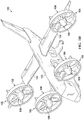
FIGs. 1A-1B illustrate a tilting ducted rotor aircraft including an electric motor stack with an integral one-piece gearbox input shaft in accordance with embodiments described herein; -
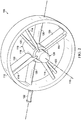
FIG. 2 illustrates a ducted rotor of the aircraft ofFIGs. 1A-1B in accordance with embodiments described herein; -
FIG. 3 is a close-up cutaway view of a portion of the ducted rotor ofFIG. 2 in accordance with embodiments described herein; -
FIG. 4A illustrates an exterior of an example electric motor stack and gear box unit wherein the electric motor stack includes an integral one-piece gearbox input shaft in accordance with embodiments described herein for implementation in aircraft having ducted rotors, such as that illustrated inFIGs. 1A-1B ; -
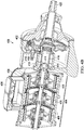
FIG. 4B illustrates a cutaway view of the example electric motor stack and gear box unit wherein the electric motor stack includes an integral one-piece gearbox input shaft illustrated inFIG. 4A ; -
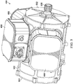
FIG. 5 is a more detailed view of the exterior of the electric motor stack ofFIGs. 4A and4B ; -
FIG. 6 is a more detailed cutaway view of the electric motor stack ofFIG. 5 ; and -
FIG. 7 is an exploded view of the electric motor stack ofFIG. 5 . - The following disclosure describes various illustrative embodiments and examples for implementing the features and functionality of the present disclosure. While particular components, arrangements, and/or features are described below in connection with various example embodiments, these are merely examples used to simplify the present disclosure and are not intended to be limiting. It will of course be appreciated that in the development of any actual embodiment, numerous implementation-specific decisions must be made to achieve the developer's specific goals, including compliance with system, business, and/or legal constraints, which may vary from one implementation to another. Moreover, it will be appreciated that, while such a development effort might be complex and time-consuming; it would nevertheless be a routine undertaking for those of ordinary skill in the art having the benefit of this disclosure.
- In the Specification, reference may be made to the spatial relationships between various components and to the spatial orientation of various aspects of components as depicted in the attached drawings. However, as will be recognized by those skilled in the art after a complete reading of the present disclosure, the devices, components, members, apparatuses, etc. described herein may be positioned in any desired orientation. Thus, the use of terms such as "above", "below", "upper", "lower", "top", "bottom", or other similar terms to describe a spatial relationship between various components or to describe the spatial orientation of aspects of such components, should be understood to describe a relative relationship between the components or a spatial orientation of aspects of such components, respectively, as the components described herein may be oriented in any desired direction. When used to describe a range of dimensions or other characteristics (e.g., time, pressure, temperature, length, width, etc.) of an element, operations, and/or conditions, the phrase "between X and Y" represents a range that includes X and Y.
- Additionally, as referred to herein in this Specification, the terms "forward", "aft", "inboard", and "outboard" may be used to describe relative relationship(s) between components and/or spatial orientation of aspect(s) of a component or components. The term "forward" may refer to a spatial direction that is closer to a front of an aircraft relative to another component or component aspect(s). The term "aft" may refer to a spatial direction that is closer to a rear of an aircraft relative to another component or component aspect(s). The term "inboard" may refer to a location of a component that is within the fuselage of an aircraft and/or a spatial direction that is closer to or along a centerline of the aircraft (wherein the centerline runs between the front and the rear of the aircraft) or other point of reference relative to another component or component aspect. The term "outboard" may refer to a location of a component that is outside the fuselage of an aircraft and/or a spatial direction that farther from the centerline of the aircraft or other point of reference relative to another component or component aspect.
- Further, the present disclosure may repeat reference numerals and/or letters in the various examples. This repetition is for the purpose of simplicity and clarity and does not in itself dictate a relationship between the various embodiments and/or configurations discussed. Example embodiments that may be used to implement the features and functionality of this disclosure will now be described with more particular reference to the accompanying FIGURES.
- Embodiments described herein is a design for an electric motor stack for driving a gearbox. In accordance with features of embodiments described herein, the electric motor stack includes three radial flux motor cores with an integral one-piece drive shaft housed within a shared housing. The drive shaft is supported through forward (or front) and rear (or back) endplates of the housing by bearings. The housing is sealed by an o-ring around the endplate mating surfaces and by a dynamic lip seal around the drive shaft in the front and back of the housing. The forward end of the drive shaft plugs into the gearbox to drive the gearbox rotors.
-
FIGs. 1A and1B illustrate anexample tiltrotor aircraft 100 that includes ducted rotors (or fans). Thetiltrotor aircraft 100 is convertible between a helicopter mode (shown inFIG. 1A ), which allows for vertical takeoff and landing, hovering, and low speed directional movement, and an airplane mode (shown in FIG. IB), which allows for forward flight as well as horizontal takeoff and landing.Aircraft 100 includes afuselage 102,wings 104, and aplurality propulsion assemblies 105 each comprising aducted fan 106 rotatably coupled tofuselage 102 orwings 104. As best shown inFIG. 2 , each ductedfan 106 includes arotor assembly 108, a flow-straightening stator assembly 110, and aduct 112 surroundingrotor assembly 108 andstator assembly 110.Rotor assembly 108 includes a plurality ofrotor blades 114 configured to rotate about amast axis 116. Rotation ofrotor blades 114 aboutmast axis 116 generates lift while operating in helicopter mode and thrust while operating in airplane mode.Stator assembly 110 is positioned downstream ofrotor blades 114 and includes astator hub 118 centrally located withinduct 112 and a plurality ofstator vanes 120 coupled betweenduct 112 andstator hub 118.Stator hub 118 may house an electric motor therein configured to produce rotational energy that drives the rotation ofrotor assembly 108. Alternatively,stator hub 118 may house a gearbox therein that drives the rotation ofrotor assembly 108, wherein the gearbox receives rotational energy from a drive shaft passing through anattachment post 122 and theadjacent stator vane 120. -
Rotor blade assemblies 108 can be collectively manipulated to selectively control direction, thrust, and lift of tilting ductedfan aircraft 100. Indeed, the collective pitch ofrotor blade assemblies 108 may be independently controlled from one another to allow for differential thrust output by ductedfans 106. For example, the collective pitch of the rotor blade assembly of one ducted fan may be higher or lower than the collective pitch of rotor blade assembly of another ducted fan such that the thrust generated by each ducted fan differs from each of the others. -
Ducted fans 106 are each convertible, relative tofuselage 102, between a horizontal position, as shown inFIGs. 1A , and a vertical position, as shown in FIG. IB.Ducted fans 106 are in the horizontal position during vertical takeoff and landing mode. Vertical takeoff and landing mode may be considered to include hover operations of tiltingducted fan aircraft 100.Ducted fans 106 are in the vertical position during forward flight mode, in which tilting ductedfan aircraft 100 is in forward flight. In forward flight mode, ductedfans 106 direct their respective thrusts in the aft direction to propel tilting ducted fan aircraft 10 forward. Tiltingducted fan aircraft 100 is operable to fly in all directions during the vertical takeoff and landing mode configuration ofFIG. 1A , although faster forward flight is achievable while in the forward flight mode configuration of FIG. IB.Ducted fans 106 may be tiltable between the vertical and horizontal positions by a rotatable shafts (not shown) extending throughwings 104 and which are rotatable in response to commands originating from a pilot and/or a flight control system. - As shown in
FIG. 3 , and as will be described in detail below, each of thepropulsion assemblies 105 utilize an electric motor stack andgear box unit 300 disposed within a respectiverotatable pylon 302 as a power source to rotate the respectiverotor hub assembly 108 via arotor mast 304. - Referring now to
FIG. 4A , illustrated therein is an electric motor stack andgearbox unit 400 that may be used as a power source to rotate a rotor hub assembly, such as rotor hub assembly 108 (FIGs. 1A and IB), and that may be used to implement electric motor stack and gear box unit 300 (FIG. 3 ).FIG. 4B is a cutaway view of the electric motor stack andgearbox unit 400. As shown inFIGs. 4A and4B , theunit 400 includes agear box 402 and an electric motor stack comprising a plurality ofelectric motors 406 and associatedpower electronics 408. In certain embodiments,electric motors 406 may be implemented as radial flux motors. - As best shown in
FIG. 4B , themotors 406 of theelectric motor stack 404 collectively drive (i.e., provide rotational power to) anintegral drive shaft 410. Each of themotors 406 is connected to thedrive shaft 410 via a respective one of overrunningclutches 412, each of which transmits torque in one direction only and permits thedrive shaft 410 to "freewheel," or continue to rotate, when the respective one of themotors 406 is stopped (e.g., upon failure of the motor). As will be described in greater detail hereinbelow, a forward end ofdrive shaft 410 is received within areceptacle 414 of thegearbox 402 for providing rotational power to asecond drive shaft 416 disposed withingearbox 404 for driving gearbox gears 418. Gearbox gears 418 operate to transfer torque to arotor shaft 420 connected to rotor assembly (FIG. 2 ). It will be noted that, althoughmotor stack 404 is illustrated as including three motors, more or fewer motors may be included without departing from the spirit or scope of embodiments described herein. -
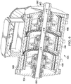
FIG. 5 is a perspective view of an exterior of theelectric motor stack 404 illustrating details of ahousing 500 thereof.FIG. 6 is a cutaway view of theelectric motor stack 404 as shown inFIG. 5 .Housing 500 includes aforward endplate 502 and arear endplate 504 through which ends ofdrive shaft 410 extend. As will be described in greater detail hereinbelow, mechanisms are provided inforward endplate 502 andrear endplate 504 for securely supporting ends ofdrive shaft 410. Aforward end 506 ofdrive shaft 410 extends through an opening in approximately a center offorward endplate 502 and is splined for interconnecting withreceptacle 414, which is splined in a complementary manner such that thedrive shaft 410 imparts rotational energy to thesecond drive shaft 416 ofgearbox 402. - As best shown in
FIG. 6 , arear end 600 of drive shaft extends through therear endplate 504 ofhousing 500. As previously noted,forward end 506 ofdrive shaft 410 is splined to mate with a splined receptacle disposed within gearbox 402 (not shown inFIG. 6 ) to drive second drive shaft 416 (not shown inFIG. 6 ). -
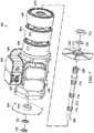
FIG. 7 is an exploded view of theelectric motor stack 404 as shown inFIGs. 5 and6 . Referring toFIG. 7 ,in addition tohousing 500 includingfront endplate 502 andrear endplate 504,motors 406,motor controller electronics 408,drive shaft 410, and overrunningclutches 412,motor stack 404 includes arear bearing 700 and a rearmain seal 702 associated with a shaft opening 706 disposed inrear endplate 504 and a forwardmain seal 708 and aforward bearing 710 associated with a shaft opening 712 disposed inforward endplate 502. As shown inFIG. 7 ,drive shaft 410 includessplined portions 716, which are engaged bymotors 406 for applying rotational power to driveshaft 410. - The
drive shaft 410 is supported through forward (or front)endplate 502 and rear (or back)endplates 504 of thehousing 500 by forward bearing 710 andrear bearing 700, respectively.Seals housing 500 around the openings 706, 712, may be implemented with o-rings around the mating surfaces ofendplates drive shaft 410 in the front and back of thehousing 500. - It should be appreciated that aircraft illustrated herein, such as
ducted rotor aircraft 100, is merely illustrative of a variety of aircraft that can implement the embodiments disclosed herein. Indeed, the various embodiments of the electric motor stack and gearbox unit described herein may be used on any aircraft that utilizes motors. Other aircraft implementations can include hybrid aircraft, tiltrotor aircraft, quad tiltrotor aircraft, unmanned aircraft, gyrocopters, airplanes, helicopters, commuter aircraft, electric aircraft, hybrid-electric aircraft, ducted fan aircraft having any number of ducted fans, tiltwing aircraft, including tiltwing aircraft having one or more interwing linkages, more or fewer ducted fans or non-ducted rotors and the like. As such, those skilled in the art will recognize that the embodiments described herein for an electric motor stack and gearbox unit can be integrated into a variety of aircraft configurations. It should be appreciated that even though aircraft are particularly well-suited to implement the embodiments of the present disclosure, non-aircraft vehicles and devices can also implement the embodiments. - The components of
rotor assembly 108 may comprise any materials suitable for use with an aircraft rotor. For example,rotor blades 114 and rotor hub may comprise carbon fiber or aluminum; and rotor mast may comprise steel or titanium. Whilerotor hub assembly 108 are shown with fourrotor blades 114, respectively, it should be understood that they may have as few as two rotor blades and may have more than four rotor blades. - Example 1 is a motor assembly including a housing having a forward endplate and a rear endplate; a plurality of motors disposed within the housing; and a drive shaft driven by the plurality of motors and having a first end extending through the forward endplate of the housing and a second end extending through the rear endplate of the housing, wherein the first end of the drive shaft is configured to engage with a gearbox.
- In Example 2, the motor assembly of Example 1 may further include each of the motors comprising a radial flux motor core.
- In Example 3, the motor assembly of any of Examples 1-2 may further include the plurality of motors together comprising a motor stack.
- In Example 4, the motor assembly of any of Examples 1-3 may further include the plurality of motors comprising three motors.
- In Example 5, the motor assembly of any of Examples 1-4 may further include the motors being connected to the drive shaft via overrunning clutches.
- In Example 6, the motor assembly of any of Examples 1-5 may further include the first end of the drive shaft extending through an opening in a center of the front endplate, the first end of the drive shaft being supported by bearings and the opening around the first end of the drive shaft being sealed by an O-ring.
- In Example 7, the motor assembly of any of Examples 1-6 may further include the second end of the drive shaft extending through an opening in a center of the rear endplate, the second end of the drive shaft being supported by bearings and the opening around the second end of the drive shaft being sealed by an O-ring.
- In Example 8, the motor assembly of any of Examples 1-7 may further include power electronics associated with the motors and disposed within the housing.
- Example 9 is a rotor system including a gear box and a motor assembly comprising a housing having a forward endplate and a rear endplate; a plurality of motors disposed within the housing; and a drive shaft driven by the plurality of motors and having a first end extending through the forward endplate of the housing and a second end extending through the rear endplate of the housing, wherein the first end of the drive shaft is configured to engage with the gearbox.
- In Example 10, the rotor system of Example 9 may further include each of the motors comprising a radial flux motor core.
- In Example 11, the rotor system of any of Examples 9-10 may further include the motors being connected to the drive shaft via overrunning clutches.
- In Example 12, the rotor system of any of Examples 9-11 may further include the first end of the drive shaft extending through an opening in a center of the front endplate, the first end of the drive shaft being supported by bearings and the opening around the first end of the drive shaft being sealed by an O-ring.
- In Example 13, the rotor system of any of Examples 9-12 may further include the second end of the drive shaft extending through an opening in a center of the rear endplate, the second end of the drive shaft being supported by bearings and the opening around the second end of the drive shaft being sealed by an O-ring.
- In Example 14, the rotor system of any of Examples 9-13 may further include power electronics associated with the motors and disposed within the housing.
- Example 15 is an aircraft including a rotor assembly, the rotor system comprising a gear box; and a motor assembly comprising a housing having a forward endplate and a rear endplate; a plurality of motors disposed within the housing; and a drive shaft driven by the plurality of motors and having a first end extending through the forward endplate of the housing and a second end extending through the rear endplate of the housing, wherein the first end of the drive shaft is configured to engage with the gearbox.
- In Example 16, the aircraft of Example 15 may further include each of the motors comprising a radial flux motor core.
- In Example 17, the aircraft of any of Examples 15-16 may further include the motors being connected to the drive shaft via overrunning clutches.
- In Example 18, the aircraft of any of Examples 15-17 may further include the first end of the drive shaft extending through an opening in a center of the front endplate, the first end of the drive shaft being supported by bearings and the opening around the first end of the drive shaft being sealed by an O-ring.
- In Example 19, the aircraft of any of Examples 15-18 may further include the second end of the drive shaft extending through an opening in a center of the rear endplate, the second end of the drive shaft being supported by bearings and the opening around the second end of the drive shaft being sealed by an O-ring.
- In Example 20, the aircraft of any of Examples 15-19 may further include power electronics associated with the motors and disposed within the housing.
- At least one embodiment is disclosed, and variations, combinations, and/or modifications of the embodiment(s) and/or features of the embodiment(s) made by a person having ordinary skill in the art are within the scope of the disclosure. Alternative embodiments that result from combining, integrating, and/or omitting features of the embodiment(s) are also within the scope of the disclosure. Where numerical ranges or limitations are expressly stated, such express ranges or limitations should be understood to include iterative ranges or limitations of like magnitude falling within the expressly stated ranges or limitations (e.g., from about 1 to about 10 includes, 2, 3, 4, etc.; greater than 0.10 includes 0.11, 0.12, 0.13, etc.). For example, whenever a numerical range with a lower limit, Rl, and an upper limit, Ru, is disclosed, any number falling within the range is specifically disclosed. In particular, the following numbers within the range are specifically disclosed: R=Rl +k * (Ru-Rl), wherein k is a variable ranging from 1 percent to 100 percent with a 1 percent increment, i.e., k is 1 percent, 2 percent, 3 percent, 4 percent, 5 percent,...50 percent, 51 percent, 52 percent,..., 95 percent, 96 percent, 95 percent, 98 percent, 99 percent, or 100 percent. Moreover, any numerical range defined by two R numbers as defined in the above is also specifically disclosed. Use of the term "optionally" with respect to any element of a claim means that the element is required, or alternatively, the element is not required, both alternatives being within the scope of the claim. Use of broader terms such as comprises, includes, and having should be understood to provide support for narrower terms such as consisting of, consisting essentially of, and comprised substantially of. Accordingly, the scope of protection is not limited by the description set out above but is defined by the claims that follow, that scope including all equivalents of the subject matter of the claims. Each and every claim is incorporated as further disclosure into the specification and the claims are embodiment(s) of the present invention. Also, the phrases "at least one of A, B, and C" and "A and/or B and/or C" should each be interpreted to include only A, only B, only C, or any combination of A, B, and C.
- The diagrams in the FIGURES illustrate the architecture, functionality, and/or operation of possible implementations of various embodiments of the present disclosure. Although several embodiments have been illustrated and described in detail, numerous other changes, substitutions, variations, alterations, and/or modifications are possible without departing from the spirit and scope of the present disclosure, as defined by the appended claims. The particular embodiments described herein are illustrative only and may be modified and practiced in different but equivalent manners, as would be apparent to those of ordinary skill in the art having the benefit of the teachings herein. Those of ordinary skill in the art would appreciate that the present disclosure may be readily used as a basis for designing or modifying other embodiments for carrying out the same purposes and/or achieving the same advantages of the embodiments introduced herein. For example, certain embodiments may be implemented using more, less, and/or other components than those described herein. Moreover, in certain embodiments, some components may be implemented separately, consolidated into one or more integrated components, and/or omitted. Similarly, methods associated with certain embodiments may be implemented using more, less, and/or other steps than those described herein, and their steps may be performed in any suitable order.
- Numerous other changes, substitutions, variations, alterations, and modifications may be ascertained to one of ordinary skill in the art and it is intended that the present disclosure encompass all such changes, substitutions, variations, alterations, and modifications as falling within the scope of the appended claims.
- One or more advantages mentioned herein do not in any way suggest that any one of the embodiments described herein necessarily provides all the described advantages or that all the embodiments of the present disclosure necessarily provide any one of the described advantages. Note that in this Specification, references to various features included in "one embodiment", "example embodiment", "an embodiment", "another embodiment", "certain embodiments", "some embodiments", "various embodiments", "other embodiments", "alternative embodiment", and the like are intended to mean that any such features are included in one or more embodiments of the present disclosure, but may or may not necessarily be combined in the same embodiments.
- As used herein, unless expressly stated to the contrary, use of the phrase "at least one of', "one or more of' and "and/or" are open ended expressions that are both conjunctive and disjunctive in operation for any combination of named elements, conditions, or activities. For example, each of the expressions "at least one of X, Y and Z", "at least one of X, Y or Z", "one or more of X, Y and Z", "one or more of X, Y or Z" and "A, B and/or C" can mean any of the following: 1) X, but not Y and not Z; 2) Y, but not X and not Z; 3) Z, but not X and not Y; 4) X and Y, but not Z; 5) X and Z, but not Y; 6) Y and Z, but not X; or 7) X, Y, and Z. Additionally, unless expressly stated to the contrary, the terms "first", "second", "third", etc., are intended to distinguish the particular nouns (e.g., blade, rotor, element, device, condition, module, activity, operation, etc.) they modify. Unless expressly stated to the contrary, the use of these terms is not intended to indicate any type of order, rank, importance, temporal sequence, or hierarchy of the modified noun. For example, "first X" and "second X" are intended to designate two X elements that are not necessarily limited by any order, rank, importance, temporal sequence, or hierarchy of the two elements. As referred to herein, "at least one of', "one or more of', and the like can be represented using the "(s)" nomenclature (e.g., one or more element(s)).
- In order to assist the United States Patent and Trademark Office (USPTO) and, additionally, any readers of any patent issued on this application in interpreting the claims appended hereto, Applicant wishes to note that the Applicant: (a) does not intend any of the appended claims to invoke paragraph (f) of 35 U.S.C.
Section 112 as it exists on the date of the filing hereof unless the words "means for" or "step for" are specifically used in the particular claims; and (b) does not intend, by any statement in the Specification, to limit this disclosure in any way that is not otherwise reflected in the appended claims.
Claims (10)
- A motor assembly comprising:a housing having a forward endplate and a rear endplate;a plurality of motors disposed within the housing; anda drive shaft driven by the plurality of motors and having a first end extending through the forward endplate of the housing and a second end extending through the rear endplate of the housing, wherein the first end of the drive shaft is configured to engage with a gearbox.
- A rotor system comprising:a gear box; anda motor assembly comprising:a housing having a forward endplate and a rear endplate;a plurality of motors disposed within the housing; anda drive shaft driven by the plurality of motors and having a first end extending through the forward endplate of the housing and a second end extending through the rear endplate of the housing, wherein the first end of the drive shaft is configured to engage with the gearbox.
- An aircraft including a rotor assembly, the rotor system comprising:a gear box; anda motor assembly comprising:a housing having a forward endplate and a rear endplate;a plurality of motors disposed within the housing; anda drive shaft driven by the plurality of motors and having a first end extending through the forward endplate of the housing and a second end extending through the rear endplate of the housing, wherein the first end of the drive shaft is configured to engage with the gearbox.
- The motor assembly of claim 1, the rotor system of claim 2, or the aircraft of claim 3, wherein each of the motors comprises a radial flux motor core.
- The motor assembly of claim 1 or 4, the rotor system of claim 2 or 4, or the aircraft of claim 3 or 4, wherein the plurality of motors comprises a motor stack.
- The motor assembly of any preceding motor assembly claim, the rotor system of any preceding rotor system claim, or the aircraft of any preceding aircraft claim, wherein the plurality of motors comprises three motors.
- The motor assembly of any preceding motor assembly claim, the rotor system of any preceding rotor system claim, or the aircraft of any preceding aircraft claim, wherein the motors are connected to the drive shaft via overrunning clutches.
- The motor assembly of any preceding motor assembly claim, the rotor system of any preceding rotor system claim, or the aircraft of any preceding aircraft claim, wherein the first end of the drive shaft extends through an opening in a center of the front endplate, the first end of the drive shaft being supported by bearings and the opening around the first end of the drive shaft being sealed by an O-ring.
- The motor assembly of any preceding motor assembly claim, the rotor system of any preceding rotor system claim, or the aircraft of any preceding aircraft claim, wherein the second end of the drive shaft extends through an opening in a center of the rear endplate, the second end of the drive shaft being supported by bearings and the opening around the second end of the drive shaft being sealed by an O-ring.
- The motor assembly of any preceding motor assembly claim, the rotor system of any preceding rotor system claim, or the aircraft of any preceding aircraft claim, further comprising power electronics associated with the motors and disposed within the housing.
Applications Claiming Priority (1)
| Application Number | Priority Date | Filing Date | Title |
|---|---|---|---|
| US16/908,286 US11831220B2 (en) | 2020-06-22 | 2020-06-22 | Electric motor stack with integral one-piece gearbox input shaft |
Publications (2)
| Publication Number | Publication Date |
|---|---|
| EP3929089A1 true EP3929089A1 (en) | 2021-12-29 |
| EP3929089B1 EP3929089B1 (en) | 2025-08-13 |
Family
ID=75936761
Family Applications (1)
| Application Number | Title | Priority Date | Filing Date |
|---|---|---|---|
| EP21173897.6A Active EP3929089B1 (en) | 2020-06-22 | 2021-05-14 | Electric motor stack with integral one-piece gearbox input shaft |
Country Status (2)
| Country | Link |
|---|---|
| US (1) | US11831220B2 (en) |
| EP (1) | EP3929089B1 (en) |
Cited By (1)
| Publication number | Priority date | Publication date | Assignee | Title |
|---|---|---|---|---|
| US20240253441A1 (en) * | 2023-01-30 | 2024-08-01 | Dana Heavy Vehicle Systems Group, Llc | Electric drive unit with removable through shaft |
Families Citing this family (8)
| Publication number | Priority date | Publication date | Assignee | Title |
|---|---|---|---|---|
| USD966191S1 (en) * | 2020-06-10 | 2022-10-11 | Sew-Eurodrive Gmbh & Co Kg | Electric motor adapter |
| USD975744S1 (en) * | 2020-06-10 | 2023-01-17 | Sew-Eurodrive Gmbh & Co Kg | Electric motor adapter |
| US11831220B2 (en) * | 2020-06-22 | 2023-11-28 | Textron Innovations Inc. | Electric motor stack with integral one-piece gearbox input shaft |
| US11390395B2 (en) | 2020-06-25 | 2022-07-19 | Textron Innovations Inc. | Aircraft rotor assembly with segmented input shaft for electric motor stack and gearbox unit |
| US11814163B2 (en) | 2021-01-13 | 2023-11-14 | Textron Innovations Inc. | Electric tiltrotor aircraft with tilting coaxial motors and gearbox |
| US11870302B2 (en) * | 2021-08-20 | 2024-01-09 | Dana Automotive Systems Group, Llc | Systems and methods for a segmented electric motor |
| FR3139554A1 (en) * | 2022-09-13 | 2024-03-15 | Airbus (S.A.S.) | Propulsion assembly comprising a transmission system, several electric motors and at least one remote coupling system, aircraft comprising at least one such propulsion assembly |
| EP4406851B1 (en) * | 2023-01-30 | 2025-10-01 | Airbus SAS | Electric propulsion assembly comprising a plurality of electric motors coupled to a same input shaft of a transmission system, aircraft comprising at least one such electric propulsion assembly |
Citations (5)
| Publication number | Priority date | Publication date | Assignee | Title |
|---|---|---|---|---|
| US20140151495A1 (en) * | 2009-01-27 | 2014-06-05 | Ira F. Kuhn, Jr. | Purebred and Hybrid Electric VTOL Tilt Rotor Aircraft |
| US20170190435A1 (en) * | 2014-07-17 | 2017-07-06 | Japan Aerospace Exploration Agency | Motorized Aircraft and Method for Determining Output and Number of Electric Motors in Motorized Aircraft |
| DE102015226836A1 (en) * | 2015-12-30 | 2017-07-06 | Siemens Aktiengesellschaft | A redundant electric drive system for driving a propulsion means of an aircraft and method for driving the propulsion means |
| US20170217600A1 (en) * | 2014-08-04 | 2017-08-03 | Israel Aerospace Industries Ltd. | Propulsion system assembly |
| US20180251226A1 (en) * | 2017-03-02 | 2018-09-06 | Bell Helicopter Textron Inc. | Hybrid propulsion drive train system for tiltrotor aircraft |
Family Cites Families (63)
| Publication number | Priority date | Publication date | Assignee | Title |
|---|---|---|---|---|
| US3290574A (en) * | 1962-07-06 | 1966-12-06 | Warner Electric Brake & Clutch | Induction motor control with plural wound rotors which are axially relatively movable for torque control |
| GB1322169A (en) | 1969-07-23 | 1973-07-04 | Kisovec A V | Convertiplanes |
| US4168459A (en) * | 1977-10-25 | 1979-09-18 | Precise Power Corporation | Non-interruptible power supply systems |
| US4476395A (en) * | 1981-10-19 | 1984-10-09 | Lockheed Corporation | Tandem-generator design for aircraft |
| US4757224A (en) * | 1985-04-26 | 1988-07-12 | Magnetics Research International Corp. | Full flux reversal variable reluctance machine |
| MY102837A (en) * | 1987-07-14 | 1992-11-30 | Satake Eng Co Ltd | Variable speed controllable induction motor |
| GB9311634D0 (en) * | 1993-06-03 | 1993-07-21 | Spooner Edward | Electromagnetic machine |
| US5990590A (en) * | 1996-09-10 | 1999-11-23 | Precise Power Corporation | Versatile AC dynamo-electric machine |
| US6700252B2 (en) | 2000-12-21 | 2004-03-02 | Schlumberger Technology Corp. | Field configurable modular motor |
| CA2499251A1 (en) | 2002-09-18 | 2004-04-01 | Philip Head | Electric motors for powering downhole tools |
| US6719244B1 (en) | 2003-02-03 | 2004-04-13 | Gary Robert Gress | VTOL aircraft control using opposed tilting of its dual propellers or fans |
| GB0327023D0 (en) | 2003-11-20 | 2003-12-24 | Head Philip | Electric motors for powering downhole tools |
| US8084908B2 (en) * | 2005-05-10 | 2011-12-27 | Komatsu Ltd. | Generator/motor mounted as an auxiliary power unit of an engine |
| US20070152523A1 (en) * | 2005-12-12 | 2007-07-05 | Franklin Electric Co., Inc. | Submersible Motor with molded encapsulated stator |
| US7309938B1 (en) * | 2006-05-31 | 2007-12-18 | Smith Kelly S | Rotary power converter |
| US20090058374A1 (en) * | 2007-08-28 | 2009-03-05 | Thomas Evans | High efficiency alternator |
| AU2008313325A1 (en) * | 2007-10-15 | 2009-04-23 | Renato Bastos Ribeiro | Multifunction Engines |
| EP2276990B1 (en) | 2008-03-24 | 2019-04-03 | Prime Datum, Inc. | Integrated fan drive system forair-cooled heat exchanger (ache) |
| GB0903423D0 (en) * | 2009-03-02 | 2009-04-08 | Rolls Royce Plc | Variable drive gas turbine engine |
| US8169110B2 (en) | 2009-10-09 | 2012-05-01 | GM Global Technology Operations LLC | Oil cooled motor/generator for an automotive powertrain |
| NO330820B1 (en) | 2009-12-24 | 2011-07-25 | Prox Dynamics As | Rotor mechanism for helicopters |
| CN101837195B (en) | 2010-01-21 | 2012-02-08 | 罗之洪 | Model airplane with vertical takeoff and landing |
| TWI401862B (en) * | 2010-07-15 | 2013-07-11 | Univ Nat Cheng Kung | Motor and electronic apparatus |
| GB2491129B (en) | 2011-05-23 | 2014-04-23 | Blue Bear Systems Res Ltd | Air vehicle |
| KR101294071B1 (en) * | 2011-10-27 | 2013-08-07 | 현대자동차주식회사 | System for hybrid vehicle |
| TWM439948U (en) * | 2012-06-26 | 2012-10-21 | Yen Shen Electric Ind Co Ltd | Motor of built-in actuator |
| JP2014121255A (en) * | 2012-12-12 | 2014-06-30 | Hyundai Motor Company Co Ltd | Drive motor of environment-friendly automobile, and rotor structure of the drive motor |
| CN104838157B (en) * | 2012-12-14 | 2017-03-15 | 维斯塔斯风力系统有限公司 | Rotating electric machine with improved bearing lubrication and related method |
| US9156545B1 (en) | 2013-05-22 | 2015-10-13 | Bell Helicopter Textron Inc. | Folding of rotorcraft rotor blades |
| GB201320246D0 (en) | 2013-11-15 | 2014-01-01 | Coreteq Ltd | Line start permanent magnet motor using a modular rotor |
| WO2015192040A1 (en) * | 2014-06-13 | 2015-12-17 | Tolomatic, Inc. | Coupled capacitive and magnetic servo motor systems |
| US10144507B2 (en) | 2014-08-28 | 2018-12-04 | Pascal Chretien | Electromagnetic distributed direct drive for aircraft |
| DE102014014588A1 (en) | 2014-10-01 | 2016-04-07 | Liebherr-Aerospace Lindenberg Gmbh | Redundant modular swivel angle motor |
| DE102015222792A1 (en) | 2015-11-18 | 2017-05-18 | Baumüller Nürnberg GmbH | motor assembly |
| US10199907B2 (en) * | 2016-02-24 | 2019-02-05 | Ge Aviation Systems Llc | Method and assembly of a power generation system |
| CN109565220B (en) * | 2016-06-10 | 2022-04-26 | 菲舍尔和佩克尔应用有限公司 | Direct drive motor arrangement |
| US10737765B2 (en) | 2016-07-01 | 2020-08-11 | Textron Innovations Inc. | Aircraft having single-axis gimbal mounted propulsion systems |
| US10625853B2 (en) | 2016-07-01 | 2020-04-21 | Textron Innovations Inc. | Automated configuration of mission specific aircraft |
| US10700579B2 (en) * | 2016-07-20 | 2020-06-30 | Ge Aviation Systems Llc | Method and assembly of a generator |
| US10106253B2 (en) | 2016-08-31 | 2018-10-23 | Bell Helicopter Textron Inc. | Tilting ducted fan aircraft generating a pitch control moment |
| US10800539B2 (en) | 2016-08-19 | 2020-10-13 | General Electric Company | Propulsion engine for an aircraft |
| NO342415B1 (en) | 2016-08-31 | 2018-05-22 | FLIR Unmanned Aerial Systems AS | Controlling blade pitch by a plurality of electric motors |
| US10252797B2 (en) | 2016-09-08 | 2019-04-09 | General Electric Company | Tiltrotor propulsion system for an aircraft |
| DE102016220234A1 (en) | 2016-10-17 | 2018-04-19 | Siemens Aktiengesellschaft | Disconnecting device for troubleshooting an electrical machine |
| JP6447662B2 (en) | 2017-05-09 | 2019-01-09 | ダイキン工業株式会社 | Electric motor system and turbo compressor provided with the same |
| US10730622B2 (en) | 2017-06-14 | 2020-08-04 | Bell Helicopter Textron Inc. | Personal air vehicle with ducted fans |
| CN111065577A (en) | 2017-08-23 | 2020-04-24 | 维曼机器人股份有限公司 | Drive mechanism |
| US10988247B2 (en) | 2017-10-19 | 2021-04-27 | Uvionix Aerospace Corporation | Unmanned aerial vehicle and propulsion system for an unmanned aerial vehicle |
| US20190135427A1 (en) | 2017-11-09 | 2019-05-09 | Bell Helicopter Textron Inc. | Tri-rotor tailsitter aircraft |
| US10752373B2 (en) | 2017-11-16 | 2020-08-25 | Textron Innovation Inc. | Air management systems for stacked motor assemblies |
| US10418868B1 (en) * | 2018-02-09 | 2019-09-17 | Kitty Hawk Corporation | Modular motor assembly |
| US20190288571A1 (en) | 2018-02-20 | 2019-09-19 | Wright Electric Inc. | Electric motors for aircraft propulsion and associated systems and methods |
| US20190270516A1 (en) | 2018-03-01 | 2019-09-05 | Bell Helicopter Textron Inc. | Propulsion Systems for Rotorcraft |
| US11312471B2 (en) | 2018-03-16 | 2022-04-26 | Joby Aero, Inc. | Aircraft drag reduction system and internally cooled motor system and aircraft using same |
| US11060562B2 (en) | 2018-04-01 | 2021-07-13 | Textron Innovations Inc. | Axially actuated locking system for a retractable driveshaft and method for use thereof |
| US10926873B2 (en) | 2018-06-20 | 2021-02-23 | Lockheed Martin Corporation | Electric powered direct drive rotor motor with integrated mechanical flight control |
| US11613375B2 (en) | 2019-05-16 | 2023-03-28 | Textron Innovations Inc. | Dual motor input with overrunning clutch |
| US12191722B2 (en) * | 2019-05-31 | 2025-01-07 | MagniX USA, Inc. | High-torque electric motor assembly |
| JP7265957B2 (en) | 2019-08-06 | 2023-04-27 | 株式会社Subaru | Redundant propulsion system and electric aircraft |
| US11565803B2 (en) | 2020-03-04 | 2023-01-31 | Textron Innovations Inc. | Electric drive system line replaceable unit with integrated cyclic actuation |
| US11831220B2 (en) * | 2020-06-22 | 2023-11-28 | Textron Innovations Inc. | Electric motor stack with integral one-piece gearbox input shaft |
| US11390395B2 (en) * | 2020-06-25 | 2022-07-19 | Textron Innovations Inc. | Aircraft rotor assembly with segmented input shaft for electric motor stack and gearbox unit |
| US11420760B2 (en) * | 2020-06-29 | 2022-08-23 | Textron Innovations Inc. | Sealed coaxial input and output shafts |
-
2020
- 2020-06-22 US US16/908,286 patent/US11831220B2/en active Active
-
2021
- 2021-05-14 EP EP21173897.6A patent/EP3929089B1/en active Active
Patent Citations (5)
| Publication number | Priority date | Publication date | Assignee | Title |
|---|---|---|---|---|
| US20140151495A1 (en) * | 2009-01-27 | 2014-06-05 | Ira F. Kuhn, Jr. | Purebred and Hybrid Electric VTOL Tilt Rotor Aircraft |
| US20170190435A1 (en) * | 2014-07-17 | 2017-07-06 | Japan Aerospace Exploration Agency | Motorized Aircraft and Method for Determining Output and Number of Electric Motors in Motorized Aircraft |
| US20170217600A1 (en) * | 2014-08-04 | 2017-08-03 | Israel Aerospace Industries Ltd. | Propulsion system assembly |
| DE102015226836A1 (en) * | 2015-12-30 | 2017-07-06 | Siemens Aktiengesellschaft | A redundant electric drive system for driving a propulsion means of an aircraft and method for driving the propulsion means |
| US20180251226A1 (en) * | 2017-03-02 | 2018-09-06 | Bell Helicopter Textron Inc. | Hybrid propulsion drive train system for tiltrotor aircraft |
Cited By (1)
| Publication number | Priority date | Publication date | Assignee | Title |
|---|---|---|---|---|
| US20240253441A1 (en) * | 2023-01-30 | 2024-08-01 | Dana Heavy Vehicle Systems Group, Llc | Electric drive unit with removable through shaft |
Also Published As
| Publication number | Publication date |
|---|---|
| EP3929089B1 (en) | 2025-08-13 |
| US11831220B2 (en) | 2023-11-28 |
| US20210399607A1 (en) | 2021-12-23 |
Similar Documents
| Publication | Publication Date | Title |
|---|---|---|
| US12172770B2 (en) | Aircraft rotor assembly with segmented input shaft for electric motor stack and gearbox unit | |
| US11831220B2 (en) | Electric motor stack with integral one-piece gearbox input shaft | |
| US12168508B2 (en) | Tilting hexrotor aircraft | |
| US11565803B2 (en) | Electric drive system line replaceable unit with integrated cyclic actuation | |
| US11554859B2 (en) | Electric drive system line replaceable unit with integrated thermal cooling | |
| US11472544B2 (en) | Electric drive system line replaceable unit with integrated collective actuation | |
| US12434823B2 (en) | Electric tiltrotor aircraft with fixed motors | |
| US12534197B2 (en) | Electric tiltrotor aircraft | |
| US11691725B2 (en) | Twin fuselage tiltrotor aircraft | |
| US11781544B2 (en) | Electric drive system for rotorcraft | |
| US12473083B2 (en) | Electric tiltrotor aircraft with tilting coaxial motors and gearbox | |
| US11807357B2 (en) | Tilting hexrotor aircraft | |
| US11702196B2 (en) | Rotor system with reconfigurable duct | |
| US11772804B2 (en) | Electric tiltrotor aircraft with offset tilting motors | |
| US11565799B2 (en) | Adjustable ducted rotor blade tip extension |
Legal Events
| Date | Code | Title | Description |
|---|---|---|---|
| PUAI | Public reference made under article 153(3) epc to a published international application that has entered the european phase |
Free format text: ORIGINAL CODE: 0009012 |
|
| STAA | Information on the status of an ep patent application or granted ep patent |
Free format text: STATUS: EXAMINATION IS IN PROGRESS |
|
| 17P | Request for examination filed |
Effective date: 20210514 |
|
| AK | Designated contracting states |
Kind code of ref document: A1 Designated state(s): AL AT BE BG CH CY CZ DE DK EE ES FI FR GB GR HR HU IE IS IT LI LT LU LV MC MK MT NL NO PL PT RO RS SE SI SK SM TR |
|
| B565 | Issuance of search results under rule 164(2) epc |
Effective date: 20211103 |
|
| GRAP | Despatch of communication of intention to grant a patent |
Free format text: ORIGINAL CODE: EPIDOSNIGR1 |
|
| STAA | Information on the status of an ep patent application or granted ep patent |
Free format text: STATUS: GRANT OF PATENT IS INTENDED |
|
| INTG | Intention to grant announced |
Effective date: 20250303 |
|
| RIC1 | Information provided on ipc code assigned before grant |
Ipc: B64D 35/021 20240101ALI20250224BHEP Ipc: B64D 27/34 20240101ALI20250224BHEP Ipc: B64D 27/31 20240101ALI20250224BHEP Ipc: H02K 16/00 20060101ALI20250224BHEP Ipc: B64C 29/00 20060101ALI20250224BHEP Ipc: B64D 35/08 20060101ALI20250224BHEP Ipc: B64D 33/08 20060101ALI20250224BHEP Ipc: B64D 27/24 20060101AFI20250224BHEP |
|
| GRAS | Grant fee paid |
Free format text: ORIGINAL CODE: EPIDOSNIGR3 |
|
| RAP1 | Party data changed (applicant data changed or rights of an application transferred) |
Owner name: TEXTRON INNOVATIONS INC. |
|
| GRAA | (expected) grant |
Free format text: ORIGINAL CODE: 0009210 |
|
| STAA | Information on the status of an ep patent application or granted ep patent |
Free format text: STATUS: THE PATENT HAS BEEN GRANTED |
|
| AK | Designated contracting states |
Kind code of ref document: B1 Designated state(s): AL AT BE BG CH CY CZ DE DK EE ES FI FR GB GR HR HU IE IS IT LI LT LU LV MC MK MT NL NO PL PT RO RS SE SI SK SM TR |
|
| REG | Reference to a national code |
Ref country code: GB Ref legal event code: FG4D |
|
| REG | Reference to a national code |
Ref country code: CH Ref legal event code: EP |
|
| REG | Reference to a national code |
Ref country code: DE Ref legal event code: R096 Ref document number: 602021035960 Country of ref document: DE |
|
| REG | Reference to a national code |
Ref country code: IE Ref legal event code: FG4D |
|
| REG | Reference to a national code |
Ref country code: NL Ref legal event code: MP Effective date: 20250813 |
|
| P01 | Opt-out of the competence of the unified patent court (upc) registered |
Free format text: CASE NUMBER: UPC_APP_0013701_3929089/2025 Effective date: 20251117 |
|
| PG25 | Lapsed in a contracting state [announced via postgrant information from national office to epo] |
Ref country code: IS Free format text: LAPSE BECAUSE OF FAILURE TO SUBMIT A TRANSLATION OF THE DESCRIPTION OR TO PAY THE FEE WITHIN THE PRESCRIBED TIME-LIMIT Effective date: 20251213 |
|
| PG25 | Lapsed in a contracting state [announced via postgrant information from national office to epo] |
Ref country code: NO Free format text: LAPSE BECAUSE OF FAILURE TO SUBMIT A TRANSLATION OF THE DESCRIPTION OR TO PAY THE FEE WITHIN THE PRESCRIBED TIME-LIMIT Effective date: 20251113 |
|
| REG | Reference to a national code |
Ref country code: LT Ref legal event code: MG9D |
|
| PG25 | Lapsed in a contracting state [announced via postgrant information from national office to epo] |
Ref country code: PT Free format text: LAPSE BECAUSE OF FAILURE TO SUBMIT A TRANSLATION OF THE DESCRIPTION OR TO PAY THE FEE WITHIN THE PRESCRIBED TIME-LIMIT Effective date: 20251215 |
|
| PG25 | Lapsed in a contracting state [announced via postgrant information from national office to epo] |
Ref country code: FI Free format text: LAPSE BECAUSE OF FAILURE TO SUBMIT A TRANSLATION OF THE DESCRIPTION OR TO PAY THE FEE WITHIN THE PRESCRIBED TIME-LIMIT Effective date: 20250813 |
|
| PG25 | Lapsed in a contracting state [announced via postgrant information from national office to epo] |
Ref country code: NL Free format text: LAPSE BECAUSE OF FAILURE TO SUBMIT A TRANSLATION OF THE DESCRIPTION OR TO PAY THE FEE WITHIN THE PRESCRIBED TIME-LIMIT Effective date: 20250813 Ref country code: HR Free format text: LAPSE BECAUSE OF FAILURE TO SUBMIT A TRANSLATION OF THE DESCRIPTION OR TO PAY THE FEE WITHIN THE PRESCRIBED TIME-LIMIT Effective date: 20250813 |
|
| PG25 | Lapsed in a contracting state [announced via postgrant information from national office to epo] |
Ref country code: GR Free format text: LAPSE BECAUSE OF FAILURE TO SUBMIT A TRANSLATION OF THE DESCRIPTION OR TO PAY THE FEE WITHIN THE PRESCRIBED TIME-LIMIT Effective date: 20251114 |
|
| PG25 | Lapsed in a contracting state [announced via postgrant information from national office to epo] |
Ref country code: SE Free format text: LAPSE BECAUSE OF FAILURE TO SUBMIT A TRANSLATION OF THE DESCRIPTION OR TO PAY THE FEE WITHIN THE PRESCRIBED TIME-LIMIT Effective date: 20250813 |
|
| PG25 | Lapsed in a contracting state [announced via postgrant information from national office to epo] |
Ref country code: LV Free format text: LAPSE BECAUSE OF FAILURE TO SUBMIT A TRANSLATION OF THE DESCRIPTION OR TO PAY THE FEE WITHIN THE PRESCRIBED TIME-LIMIT Effective date: 20250813 |
|
| PG25 | Lapsed in a contracting state [announced via postgrant information from national office to epo] |
Ref country code: BG Free format text: LAPSE BECAUSE OF FAILURE TO SUBMIT A TRANSLATION OF THE DESCRIPTION OR TO PAY THE FEE WITHIN THE PRESCRIBED TIME-LIMIT Effective date: 20250813 Ref country code: PL Free format text: LAPSE BECAUSE OF FAILURE TO SUBMIT A TRANSLATION OF THE DESCRIPTION OR TO PAY THE FEE WITHIN THE PRESCRIBED TIME-LIMIT Effective date: 20250813 |
|
| PG25 | Lapsed in a contracting state [announced via postgrant information from national office to epo] |
Ref country code: RS Free format text: LAPSE BECAUSE OF FAILURE TO SUBMIT A TRANSLATION OF THE DESCRIPTION OR TO PAY THE FEE WITHIN THE PRESCRIBED TIME-LIMIT Effective date: 20251113 |
|
| PG25 | Lapsed in a contracting state [announced via postgrant information from national office to epo] |
Ref country code: ES Free format text: LAPSE BECAUSE OF FAILURE TO SUBMIT A TRANSLATION OF THE DESCRIPTION OR TO PAY THE FEE WITHIN THE PRESCRIBED TIME-LIMIT Effective date: 20250813 |
|
| REG | Reference to a national code |
Ref country code: AT Ref legal event code: MK05 Ref document number: 1824441 Country of ref document: AT Kind code of ref document: T Effective date: 20250813 |
|
| PG25 | Lapsed in a contracting state [announced via postgrant information from national office to epo] |
Ref country code: SM Free format text: LAPSE BECAUSE OF FAILURE TO SUBMIT A TRANSLATION OF THE DESCRIPTION OR TO PAY THE FEE WITHIN THE PRESCRIBED TIME-LIMIT Effective date: 20250813 |
|
| PG25 | Lapsed in a contracting state [announced via postgrant information from national office to epo] |
Ref country code: DK Free format text: LAPSE BECAUSE OF FAILURE TO SUBMIT A TRANSLATION OF THE DESCRIPTION OR TO PAY THE FEE WITHIN THE PRESCRIBED TIME-LIMIT Effective date: 20250813 |
|
| PG25 | Lapsed in a contracting state [announced via postgrant information from national office to epo] |
Ref country code: AT Free format text: LAPSE BECAUSE OF FAILURE TO SUBMIT A TRANSLATION OF THE DESCRIPTION OR TO PAY THE FEE WITHIN THE PRESCRIBED TIME-LIMIT Effective date: 20250813 |
|
| PG25 | Lapsed in a contracting state [announced via postgrant information from national office to epo] |
Ref country code: IT Free format text: LAPSE BECAUSE OF FAILURE TO SUBMIT A TRANSLATION OF THE DESCRIPTION OR TO PAY THE FEE WITHIN THE PRESCRIBED TIME-LIMIT Effective date: 20250813 |
|
| PG25 | Lapsed in a contracting state [announced via postgrant information from national office to epo] |
Ref country code: CZ Free format text: LAPSE BECAUSE OF FAILURE TO SUBMIT A TRANSLATION OF THE DESCRIPTION OR TO PAY THE FEE WITHIN THE PRESCRIBED TIME-LIMIT Effective date: 20250813 |
|
| PG25 | Lapsed in a contracting state [announced via postgrant information from national office to epo] |
Ref country code: EE Free format text: LAPSE BECAUSE OF FAILURE TO SUBMIT A TRANSLATION OF THE DESCRIPTION OR TO PAY THE FEE WITHIN THE PRESCRIBED TIME-LIMIT Effective date: 20250813 Ref country code: SK Free format text: LAPSE BECAUSE OF FAILURE TO SUBMIT A TRANSLATION OF THE DESCRIPTION OR TO PAY THE FEE WITHIN THE PRESCRIBED TIME-LIMIT Effective date: 20250813 |
|
| REG | Reference to a national code |
Ref country code: DE Ref legal event code: R097 Ref document number: 602021035960 Country of ref document: DE |
|
| PLBE | No opposition filed within time limit |
Free format text: ORIGINAL CODE: 0009261 |
|
| STAA | Information on the status of an ep patent application or granted ep patent |
Free format text: STATUS: NO OPPOSITION FILED WITHIN TIME LIMIT |
|
| REG | Reference to a national code |
Ref country code: CH Ref legal event code: L10 Free format text: ST27 STATUS EVENT CODE: U-0-0-L10-L00 (AS PROVIDED BY THE NATIONAL OFFICE) Effective date: 20260624 |
|
| PG25 | Lapsed in a contracting state [announced via postgrant information from national office to epo] |
Ref country code: LT Free format text: LAPSE BECAUSE OF FAILURE TO SUBMIT A TRANSLATION OF THE DESCRIPTION OR TO PAY THE FEE WITHIN THE PRESCRIBED TIME-LIMIT Effective date: 20250813 |
|
| PGFP | Annual fee paid to national office [announced via postgrant information from national office to epo] |
Ref country code: GB Payment date: 20260527 Year of fee payment: 6 |
|
| PGFP | Annual fee paid to national office [announced via postgrant information from national office to epo] |
Ref country code: DE Payment date: 20260528 Year of fee payment: 6 |
|
| 26N | No opposition filed |
Effective date: 20260515 |
|
| PGFP | Annual fee paid to national office [announced via postgrant information from national office to epo] |
Ref country code: FR Payment date: 20260525 Year of fee payment: 6 |