EP3929078A1 - Helicopter - Google Patents
Helicopter Download PDFInfo
- Publication number
- EP3929078A1 EP3929078A1 EP20182389.5A EP20182389A EP3929078A1 EP 3929078 A1 EP3929078 A1 EP 3929078A1 EP 20182389 A EP20182389 A EP 20182389A EP 3929078 A1 EP3929078 A1 EP 3929078A1
- Authority
- EP
- European Patent Office
- Prior art keywords
- axis
- corrugated element
- corrugation
- helicopter according
- joint
- Prior art date
- Legal status (The legal status is an assumption and is not a legal conclusion. Google has not performed a legal analysis and makes no representation as to the accuracy of the status listed.)
- Granted
Links
Images


Classifications
-
- B—PERFORMING OPERATIONS; TRANSPORTING
- B64—AIRCRAFT; AVIATION; COSMONAUTICS
- B64C—AEROPLANES; HELICOPTERS
- B64C27/00—Rotorcraft; Rotors peculiar thereto
- B64C27/04—Helicopters
- B64C27/12—Rotor drives
-
- B—PERFORMING OPERATIONS; TRANSPORTING
- B64—AIRCRAFT; AVIATION; COSMONAUTICS
- B64C—AEROPLANES; HELICOPTERS
- B64C27/00—Rotorcraft; Rotors peculiar thereto
- B64C27/04—Helicopters
- B64C27/12—Rotor drives
- B64C27/14—Direct drive between power plant and rotor hub
-
- B—PERFORMING OPERATIONS; TRANSPORTING
- B64—AIRCRAFT; AVIATION; COSMONAUTICS
- B64C—AEROPLANES; HELICOPTERS
- B64C27/00—Rotorcraft; Rotors peculiar thereto
- B64C27/82—Rotorcraft; Rotors peculiar thereto characterised by the provision of an auxiliary rotor or fluid-jet device for counter-balancing lifting rotor torque or changing direction of rotorcraft
-
- F—MECHANICAL ENGINEERING; LIGHTING; HEATING; WEAPONS; BLASTING
- F16—ENGINEERING ELEMENTS AND UNITS; GENERAL MEASURES FOR PRODUCING AND MAINTAINING EFFECTIVE FUNCTIONING OF MACHINES OR INSTALLATIONS; THERMAL INSULATION IN GENERAL
- F16D—COUPLINGS FOR TRANSMITTING ROTATION; CLUTCHES; BRAKES
- F16D3/00—Yielding couplings, i.e. with means permitting movement between the connected parts during the drive
- F16D3/50—Yielding couplings, i.e. with means permitting movement between the connected parts during the drive with the coupling parts connected by one or more intermediate members
- F16D3/72—Yielding couplings, i.e. with means permitting movement between the connected parts during the drive with the coupling parts connected by one or more intermediate members with axially-spaced attachments to the coupling parts
- F16D3/74—Yielding couplings, i.e. with means permitting movement between the connected parts during the drive with the coupling parts connected by one or more intermediate members with axially-spaced attachments to the coupling parts the intermediate member or members being made of rubber or other rubber-like flexible material
-
- F—MECHANICAL ENGINEERING; LIGHTING; HEATING; WEAPONS; BLASTING
- F16—ENGINEERING ELEMENTS AND UNITS; GENERAL MEASURES FOR PRODUCING AND MAINTAINING EFFECTIVE FUNCTIONING OF MACHINES OR INSTALLATIONS; THERMAL INSULATION IN GENERAL
- F16D—COUPLINGS FOR TRANSMITTING ROTATION; CLUTCHES; BRAKES
- F16D3/00—Yielding couplings, i.e. with means permitting movement between the connected parts during the drive
- F16D3/50—Yielding couplings, i.e. with means permitting movement between the connected parts during the drive with the coupling parts connected by one or more intermediate members
- F16D3/72—Yielding couplings, i.e. with means permitting movement between the connected parts during the drive with the coupling parts connected by one or more intermediate members with axially-spaced attachments to the coupling parts
- F16D3/74—Yielding couplings, i.e. with means permitting movement between the connected parts during the drive with the coupling parts connected by one or more intermediate members with axially-spaced attachments to the coupling parts the intermediate member or members being made of rubber or other rubber-like flexible material
- F16D2003/745—Tyre type coupling, i.e. bellows with only one fold
-
- F—MECHANICAL ENGINEERING; LIGHTING; HEATING; WEAPONS; BLASTING
- F16—ENGINEERING ELEMENTS AND UNITS; GENERAL MEASURES FOR PRODUCING AND MAINTAINING EFFECTIVE FUNCTIONING OF MACHINES OR INSTALLATIONS; THERMAL INSULATION IN GENERAL
- F16D—COUPLINGS FOR TRANSMITTING ROTATION; CLUTCHES; BRAKES
- F16D2200/00—Materials; Production methods therefor
- F16D2200/006—Materials; Production methods therefor containing fibres or particles
Definitions
- the present invention relates to a helicopter.
- helicopters generally comprise:
- the motor member comprises, in turn, an output shaft and a first stator rotatably supporting the output shaft around the first axis.
- the main transmission comprises, in turn, an input shaft and a second stator rotatably supporting the input shaft around the second axis.
- the helicopter also comprises:
- the flexible rotating joint transfers a torque while allowing at the same time an angular misalignment by a few degrees between the output shaft of the motor member and the input shaft of the main transmission.
- the latter is subject to angular movements due to the loads of the rotor in operating conditions and/or due to the different operating regimes of the drive shaft and power take-off.
- the articulated joint must allow, in addition to the transmission of a second torque between the first and the second sleeve, an angular inclination by some degree between the aforesaid first and second sleeves for the same reasons described above with reference to the output member of the drive shaft.
- the articulated joint is static, i.e. it does not rotate around the axes of the first and second sleeves.
- the articulated joint serves only as a joint to allow for the misalignments mentioned above.
- the articulated joint is also hollow and houses respective adjacent portions of the input and output shafts and the flexible joint of the drive shaft.
- the flexible joint is integrally rotatable with the output shaft of the motor member and with the input shaft of the transmission.
- the loads to which the articulated joint is subjected comprise a torque of variable entity which in normal operating conditions derives from the reaction of the motor torque.
- the torque can reach much higher values than under normal operating conditions.
- the articulated joint is also subjected to axial and shear loads, both under normal conditions and under particular conditions.
- the axial and shear load values can be very high because the element serves to prevent the motor from collapsing on the transmission.
- the inclination between the first and the second sleeve occurs in a pair of planes that are parallel to the rotation axes of the input and output shaft, that is, in the flexural planes of the aforesaid input and output shafts.
- the articulated joints of the known type comprise, in particular, a plurality of rigid elements articulated between them in such a way as to allow the transmission of a high torque value and to allow the necessary misalignments/inclinations between the output shaft of the motor member and the input shaft of the transmission.
- the object of the present invention is to realise a helicopter which allows to satisfy at least one of the needs specified above in a simple and economical way.
- this object is achieved by a helicopter as claimed in claim 1.
- 1 indicates a helicopter.
- the helicopter 1 essentially comprises:
- the helicopter 1 also comprises a main transmission group 7 interposed between the motor group 3 and a control shaft 8 of the rotor 4.
- the motor group 3 ( Figure 2 ) essentially comprises:
- the transmission group 7 essentially comprises:
- the helicopter 1 also comprises a joint 25 rotatable around the axes C, D and interposed between the output shaft 12 and the input shaft 21.
- the joint 25 is adapted to transmit the driving torque generated by the motor group 3 to the input shaft 21 of the transmission group 7.
- the joint 25 comprises a pair of discs 27a, 27b carried respectively by opposite ends 28a, 28b adjacent to the respective output shaft 12 and input shaft 21.
- the stators 11, 20 have respective sleeves 29, 30 which are angularly fixed with respect to the relative axes C, D.
- the sleeves 29, 30 are hollow and respectively house a portion of the output shaft 12 and a portion of the input shaft 21 defining the respective ends 28a, 28b.
- the helicopter 1 also comprises a joint 35 interposed between the sleeves 29, 30, angularly fixed with respect to the axes C, D and configured to allow an angle of inclination, for example by two degrees, between the sleeves 29, 30 in a pair of planes parallel to the axis C, D.
- said planes correspond to the planes of elastic inflection of the output shaft 12 and the input shaft 21.
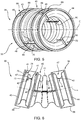
- the joint 35 comprises a corrugated element 36 made of an elastically deformable material, interposed between the sleeves 29, 30 and adapted to allow said angle of inclination through its own elastic deformation.
- the corrugation of the corrugated element 36 allows to obtain an elastic flexural deformability such as to allow the inclination between the sleeves 29, 30 in the aforesaid planes.
- the corrugated element 36 extends axial-symmetrically around an axis E, in the case illustrated.
- the axis E coincides with the axes C, D when the corrugated element 36 is undeformed ( Figure 5 ) and is inflected with respect to the axes C, D when the corrugated element 36 deforms flexurally ( Figure 6 ).
- corrugation means, in the following of the present description, a continuous succession or continuous in some stretches and periodic succession of annular ridges and grooves around the axis E.
- the corrugation has, in a section containing the axis E:
- pitch p of the corrugation The distance between two consecutive ridges (grooves) along the longitudinal direction is called pitch p of the corrugation.
- the distance between the ridges and the grooves along the transverse direction is called height h of the corrugation.
- the joint 35 essentially comprises a pair of flanges 38, 39 protruding from respective axial ends of the sleeves 29, 30 opposite respectively to the motor group 3 and to the transmission group 7.
- the flanges 38, 39 extend orthogonally to the respective axes C, D.
- the corrugated element 36 is axially interposed between the flanges 38, 39 and is connected to the flanges 38, 39 itself.
- the element 36 has a corrugation 40 with a longitudinal direction of extension parallel to the axis E and a thickness radial to the axis E.
- the corrugation 40 comprises respective pluralities of rings 41, 42.
- the rings 41, 42 are alternated between them parallel to the axis E and define respective radial ends opposite one another of the corrugation 40.
- the rings 41 are arranged at a first radial distance from the axis E and define respective ridges of the corrugation 40.
- the rings 42 are arranged at a second radial distance from the axis E smaller than the aforesaid first axial distance and define respective grooves of the corrugation 40.
- the rings 41 (42) are all arranged at the same first (second) radial distance from the axis E, in the case illustrated.
- the corrugation 40 has a plurality of connecting annular stretches 47, each interposed between a respective ring 41 and the respective rings 42 adjacent thereto.
- Each stretch 47 extends starting from the respective ring 41 at progressively increasing axial and radial distances towards the respective rings 42.
- the corrugation 40 has a coil shape in the section parallel to the axis E, in the case illustrated.
- the corrugation 40 is symmetrical with respect to the axis E.
- the rings 41, 42 lie on respective planes orthogonal to the axis E.
- the corrugation 40 also comprises axial ends 43, 44 opposite one another and of annular shape.
- the ends 43, 44 are connected to respective radially external ends 45, 46 of respective flanges 38, 39.
- the joint 35 also comprises a plurality of ribs 69, 70 connected to the element 36 and adapted to confer axial rigidity to the joint 35 itself.
- the ribs 69, 70 are arranged externally to the element 36 with reference to the axis E and eccentrically with respect to the axis E itself.
- Each rib 69, 70 is elongated along the axis E and extends over an arc around the axis E of a smaller width than the length of the rib 69, 70 along the axis E.
- each rib 69, 70 has a total dimension that is radial to the axis E which is greater than its extension circumferentially to the axis E itself.
- Each rib 69, 70 is axially delimited by a pair of stretches 81, 82 opposite one another and shaped like an arc ( Figure 7 ).
- Each rib 69, 70 is also delimited in a position radially external to the axis E by a straight stretch 89 that is parallel to the axis E.
- Each rib 69, 70 is furthermore delimited in a position radially internal to the axis E by a respective corrugation 71 coupled to a respective portion 48 of the corrugation 40 of the element 36.
- the stretch 89 and the corrugation 71 are radially opposite one another and extend between the stretches 81, 82.
- the corrugation 71 has a longitudinal direction of extension parallel to the axis E and a thickness radial to the axis E.
- the corrugation 71 comprises respective pluralities of ridges 72 and grooves 73, in the case illustrated.
- the ridges 72 and the grooves 73 are alternated between them parallel to the axis E and define respective radial ends opposite one another of the corrugation 40.
- the ridges 72 are arranged at a first radial distance from the axis E.
- the grooves 73 are arranged at a second radial distance from the axis E that is smaller than the aforesaid first radial distance.
- the ridges 72 are all arranged at the same first (second) radial distance from the axis E, in the case illustrated.
- the ridges 72 and the grooves 73 respectively define the points of maximum and minimum distance of each rib 69, 70 from the axis E.
- the corrugation 71 has a plurality of connecting stretches 74, each interposed between a respective ridge 72 and the respective grooves 73 adjacent thereto.
- Each stretch 74 extends starting from the respective ridge 72 at progressively increasing axial and radial distances towards the respective grooves 73.
- the corrugation 71 has a coil shape in the section parallel to the axis E, in the case illustrated.
- Each rib 69 is connected, glued in the illustrated case, on the relative portion of the corrugation 40, so that the respective ridges 72 and the respective grooves 73 are radially connected to respective rings 41, 42 of the corrugation 40 and the stretches 74 are radially connected to respective stretches 47 of the corrugation 40 ( Figure 3 ).
- each corrugation 71 comprises two ridges 72 and a groove 73 axially interposed between the ridges 72.
- the ridges 72 define opposite axial ends 75, 76 of the corrugation 71, in the case illustrated.
- each rib 40 further comprises:
- the flanges 180, 181, 182, 183 extend like an arc over a length greater than the circumferential extension of the ribs 69, 70.
- the flanges 180, 181 each comprise a surface 184 orthogonal to the axis E and a surface 185 protruding in a cantilever manner from the surface 184 parallel to the axis E.
- the surface 185 of the flange 180 extends in a cantilever manner from the relative surface 184 towards the surface 185 of the flange 181.
- the element 36 further comprises a plurality of strips 100, acting as joint covers, associated with respective ribs 69, 70.
- the strips 100 are housed inside the element 36.
- element 36 is obtained by approaching and connecting a pair of half-elements 37 (only one of which is partially visible in Figure 3 ), which each extend over one hundred and eighty degrees in a section obtained with a plane orthogonal to the axis E.
- the flanges 180, 181, 182, 183 and the strips 100 connect between them the aforesaid half-elements 37 respectively in a position that is radially external and radially internal to the axis E.
- the flanges 180, 181, 182, 183 help to react to the loads parallel to the axis E while the strips 100 substantially perform the function of joint cover.
- the corrugation 40 is radially interposed between each strip 100 and the relative rib 69, 70.
- Each strip 100 is delimited in an axial direction by two arched stretches 101 arranged at respective flanges 180, 181.
- Each strip 100 is delimited in a circumferential direction by a pair of stretches 103 that are parallel to each other and axially interposed between the stretches 101.
- Each strip 100 defines a relative corrugation 104 with a longitudinal direction of extension parallel to the axis E and a thickness radial to the axis E.
- the corrugation 104 comprises respective pluralities of ridges 105 and grooves 106 shaped as arc sectors around the axis E.
- the ridges 105 and the grooves 106 are alternated between them parallel to the axis E and define respective radial ends opposite one another of the respective corrugation 104.
- the ridges 105 are arranged at a first radial distance from the axis E.
- the grooves 106 are arranged at a second radial distance from the axis E that is smaller than the aforesaid first axial distance.
- the ridges 105 are all arranged at the same first (second) radial distance from the axis E, in the case illustrated.
- the ridges 105 and the grooves 106 respectively define the points of maximum and minimum distance of the corrugation 104 from the axis E.
- the ridges 105 and the grooves 106 are shaped as respective circumference arcs having a centre on the axis E.
- the corrugation 104 has a plurality of connecting stretches 107 shaped like an arc and each interposed between a respective ridge 105 and the respective grooves 106 adjacent thereto.
- Each stretch 107 extends starting from the respective ridge 105 at progressively increasing axial and radial distances towards the respective grooves 106.
- the corrugation 104 has a coil shape in the section parallel to the axis E, in the case illustrated.
- each strip 100 is made of aluminium or composite material.
- the joint 35 comprises a plurality of pairs of ribs 69, 70 coupled to the element 36 and arranged axially consecutive to each other.
- the ribs 69, 70 of each pair are angularly spaced, by one hundred and eighty degrees in the case illustrated.
- the ribs 69, 70 of each pair are arranged in the same axial position with respect to the axis E.
- the ribs 69, 70 of pairs that are consecutive between them along the axis E are angularly offset, by one hundred and eighty degrees in the case illustrated.
- each rib 69, 70 comprises a relative stretch 90 ( Figure 5 ) housed inside the element 36 and radially opposite to the respective stretch 89.
- the element 36 is made of composite material, in particular a fibre-reinforced laminate, while the ribs 69, 70 are made of aluminium or other metal, or of composite or a combination of metal and composite.
- the element 36 houses the discs 27a, 27b and the portions of the output shaft 12 and the output shaft 21 connected to the respective flanges 38, 39 ( Figure 2 ).
- the motor group 3 drags the output shaft 11 in rotation around the axis C.
- the output shaft 12 drives the input shaft 21 of the transmission 7 in rotation around the axis D.
- the transmission 7 drives the control shaft 8 of the rotor 4 in rotation around the axis A.
- the corrugated element 36 of the joint 35 connects the sleeves 29, 30 carried by the stators 11, 20 respectively of the motor group 3 and of the transmission 7.
- the corrugated element 36 allows to transmit to the sleeve 30 the torques directed along the axis E and transmitted from the output shaft 12 to the sleeve 29.
- the corrugated element 36 allows the inclination between the axes C, D in a pair of planes parallel to the axes C, D, E themselves.
- the ribs 69, 70 confer axial rigidity to the joint 35 thus allowing the transmission of loads that are parallel to the axes C, D, E between the sleeves 29, 30.
- the joint 35 interposed between the output shaft 12 of the motor group 3 and the input shaft 21 of the transmission 7 comprises the corrugated element 36 with a high torsional rigidity and flexural deformability.
- Said torsional rigidity and flexural deformability are determined by the corrugation 40, which has a length parallel to the axis E and a thickness transverse to the axis E.
- the joint 35 allows to efficiently transmit between the sleeves 29, 30 the reaction torque from the output shaft 12 under normal operating conditions, and also the torque due to particular operating conditions, for example in the case of blockage of the motor group 3.
- the joint 35 allows the inclination between the sleeves 29, 30 in a pair of planes that are parallel to the axes C, D, E.
- the corrugations 40 allow to decouple the rigidities and the load paths.
- the ribs 69, 70 confer the joint 35 the necessary axial rigidity adapted to allow the transmission of forces between the sleeves 29, 30 parallel to the axes E, C, D, without significantly compromising the flexural flexibility of the joint.
- the ribs 69, 70 further help to decouple the rigidities and the load paths of the joint 35.
- the corrugations 71 of the ribs 69, 70 are axially constrained to the corrugations 40 of the element 36. This allows to stabilize the ribs 69, 70 considerably, increasing the maximum peak load stress that can be supported by the ribs 69, 70 themselves.
- the aforesaid characteristics of the joint 35 can be optimized by suitably choosing the lamination sequence of the fibre-reinforced material of the element 36 and of the ribs 69, 70.
- helicopter 1 described and illustrated herein may be subject to modifications and variations without thereby departing from the scope of protection defined by the claims.
- corrugations 40, 71, 104 could be shaped at least in part as broken segments joined to each other and/or with curved stretches.
- the corrugated element 36 could not be axial-symmetrical around the axis E.
- the corrugated element 36 could have an oval section so as to obtain flexural rigidities that are different from each other in the different planes parallel to the axis E.
- the corrugated element 36 could have a conical or barrel shape.
- the axes C, D could be inclined or skewed with respect to each other.
Landscapes
- Engineering & Computer Science (AREA)
- Mechanical Engineering (AREA)
- Aviation & Aerospace Engineering (AREA)
- General Engineering & Computer Science (AREA)
- Shafts, Cranks, Connecting Bars, And Related Bearings (AREA)
- Flexible Shafts (AREA)
- Connection Of Motors, Electrical Generators, Mechanical Devices, And The Like (AREA)
- Vibration Prevention Devices (AREA)
Abstract
Description
- The present invention relates to a helicopter.
- As is known, helicopters generally comprise:
- a motor member, for example a turbine;
- a main rotor; and
- a main transmission formed by a train of gears which transmit the motion from an output shaft of the motor member to the main rotor with a suitable reduction ratio.
- The motor member comprises, in turn, an output shaft and a first stator rotatably supporting the output shaft around the first axis.
- The main transmission comprises, in turn, an input shaft and a second stator rotatably supporting the input shaft around the second axis.
- According to a known solution, the helicopter also comprises:
- a flexible rotating joint, for example with discs, interposed between the output shaft of the motor member and the input shaft of the main transmission to allow the transmission of a first torque from the output shaft of the motor member to the input shaft of the main transmission; and
- a static articulated joint, for example a cardan joint, interposed between a first sleeve connected to the first stator of the motor member and a second sleeve connected to the second stator of the main transmission.
- Both the flexible joint and the articulated joint must satisfy precise functional requirements.
- In greater detail, the flexible rotating joint transfers a torque while allowing at the same time an angular misalignment by a few degrees between the output shaft of the motor member and the input shaft of the main transmission. The latter is subject to angular movements due to the loads of the rotor in operating conditions and/or due to the different operating regimes of the drive shaft and power take-off.
- Similarly, the articulated joint must allow, in addition to the transmission of a second torque between the first and the second sleeve, an angular inclination by some degree between the aforesaid first and second sleeves for the same reasons described above with reference to the output member of the drive shaft.
- Unlike the flexible joint, the articulated joint is static, i.e. it does not rotate around the axes of the first and second sleeves. The articulated joint serves only as a joint to allow for the misalignments mentioned above.
- The articulated joint is also hollow and houses respective adjacent portions of the input and output shafts and the flexible joint of the drive shaft.
- The flexible joint is integrally rotatable with the output shaft of the motor member and with the input shaft of the transmission.
- The loads to which the articulated joint is subjected comprise a torque of variable entity which in normal operating conditions derives from the reaction of the motor torque. In particular emergency cases, for example in case of a blockage of the motor member, the torque can reach much higher values than under normal operating conditions. Furthermore, the articulated joint is also subjected to axial and shear loads, both under normal conditions and under particular conditions.
- For example, in case of an impact, the axial and shear load values can be very high because the element serves to prevent the motor from collapsing on the transmission.
- The inclination between the first and the second sleeve occurs in a pair of planes that are parallel to the rotation axes of the input and output shaft, that is, in the flexural planes of the aforesaid input and output shafts.
- The articulated joints of the known type comprise, in particular, a plurality of rigid elements articulated between them in such a way as to allow the transmission of a high torque value and to allow the necessary misalignments/inclinations between the output shaft of the motor member and the input shaft of the transmission.
- The need to connect the first sleeve of the motor member and the second sleeve of the transmission with an articulated joint which allows a high load capacity and torsional, axial and shear rigidity coupled with low flexural rigidity is felt in the sector.
- This is in order to allow the transmission of the torque parallel to the rotation axes of the output and input shafts and, at the same time, the inclination of the first and second sleeves in the planes parallel to said rotation axes.
- Furthermore, the need to satisfy these requirements by reducing the number of articulated components, the weights and the overall costs is felt in the sector.
- The object of the present invention is to realise a helicopter which allows to satisfy at least one of the needs specified above in a simple and economical way.
- According to the invention, this object is achieved by a helicopter as claimed in
claim 1. - For a better understanding of the present invention, a preferred non-limiting embodiment is described below, purely by way of example and with the aid of the attached drawings, in which:
-
Figure 1 is a side view of a helicopter realised according to the dictates of a first embodiment of the present invention;-
Figure 2 illustrates on an enlarged and partially sectioned scale some components of the helicopter ofFigure 1 , with parts removed for clarity's sake; -
Figure 3 illustrates a perspective view and on a further enlarged scale of some details of a static joint of the helicopter ofFigures 1 and2 , with parts removed for clarity's sake;
-
-
Figure 4 illustrates a perspective view according to a first visual angle of a particular embodiment of the static joint of the helicopter ofFigures 1 and2 in an undeformed condition; -
Figure 5 illustrates a perspective view, on an enlarged scale and according to a second visual angle of a different embodiment of the static joint ofFigure 4 in an undeformed condition; -
Figure 6 illustrates a side view of the static joint ofFigure 5 in a flexurally deformed condition; and -
Figure 7 illustrates a side view of the static joint ofFigures 5 to 6 in an undeformed condition. - With reference to the attached
figures, 1 indicates a helicopter. - The
helicopter 1 essentially comprises: - a
fuselage 2; - a
motor group 3 formed, for example by one or more turbo-shaft systems 10; - a
main rotor 4 located at a top of thefuselage 2, rotatable around an axis A, and adapted to provide the lift and thrust necessary for the support and movement of thehelicopter 1; and - an
anti-torque rotor 5, which is placed, in the case illustrated, at atail end 6 of thefuselage 2 and is rotatable around its own axis transverse to the axis B. - The
helicopter 1 also comprises amain transmission group 7 interposed between themotor group 3 and acontrol shaft 8 of therotor 4. - The motor group 3 (
Figure 2 ) essentially comprises: - a
stator 11 housing thesystems 10; - an
output shaft 12 of thesystems 10 and rotatable around an axis C. - The
transmission group 7 essentially comprises: - a
stator 20; and - an
input shaft 21 rotatable around an axis D, coinciding with the axis C in the case illustrated. - The
helicopter 1 also comprises ajoint 25 rotatable around the axes C, D and interposed between theoutput shaft 12 and theinput shaft 21. - The
joint 25 is adapted to transmit the driving torque generated by themotor group 3 to theinput shaft 21 of thetransmission group 7. - In the case illustrated, the
joint 25 comprises a pair ofdiscs opposite ends respective output shaft 12 andinput shaft 21. - The
stators respective sleeves - The
sleeves output shaft 12 and a portion of theinput shaft 21 defining therespective ends - The
helicopter 1 also comprises ajoint 35 interposed between thesleeves sleeves - In greater detail, said planes correspond to the planes of elastic inflection of the
output shaft 12 and theinput shaft 21. - Advantageously, the
joint 35 comprises acorrugated element 36 made of an elastically deformable material, interposed between thesleeves - In other words, the corrugation of the
corrugated element 36 allows to obtain an elastic flexural deformability such as to allow the inclination between thesleeves - The
corrugated element 36 extends axial-symmetrically around an axis E, in the case illustrated. - The axis E coincides with the axes C, D when the
corrugated element 36 is undeformed (Figure 5 ) and is inflected with respect to the axes C, D when thecorrugated element 36 deforms flexurally (Figure 6 ). - The term "corrugation" means, in the following of the present description, a continuous succession or continuous in some stretches and periodic succession of annular ridges and grooves around the axis E.
- The corrugation has, in a section containing the axis E:
- a longitudinal direction of extension along which the ridges and the grooves are periodically repeated; and
- a transverse direction orthogonal to the direction of extension and along which the ridges and the grooves extend at a distance between them.
- The distance between two consecutive ridges (grooves) along the longitudinal direction is called pitch p of the corrugation.
- The distance between the ridges and the grooves along the transverse direction is called height h of the corrugation.
- With reference to
Figure 2 , the joint 35 essentially comprises a pair offlanges sleeves motor group 3 and to thetransmission group 7. - In the case illustrated, the
flanges - The
corrugated element 36 is axially interposed between theflanges flanges - The
element 36 has acorrugation 40 with a longitudinal direction of extension parallel to the axis E and a thickness radial to the axis E. - The
corrugation 40 comprises respective pluralities ofrings - The
rings corrugation 40. - The
rings 41 are arranged at a first radial distance from the axis E and define respective ridges of thecorrugation 40. - The
rings 42 are arranged at a second radial distance from the axis E smaller than the aforesaid first axial distance and define respective grooves of thecorrugation 40. - The rings 41 (42) are all arranged at the same first (second) radial distance from the axis E, in the case illustrated.
- The
corrugation 40 has a plurality of connectingannular stretches 47, each interposed between arespective ring 41 and therespective rings 42 adjacent thereto. - Each
stretch 47 extends starting from therespective ring 41 at progressively increasing axial and radial distances towards the respective rings 42. - The
corrugation 40 has a coil shape in the section parallel to the axis E, in the case illustrated. - The
corrugation 40 is symmetrical with respect to the axis E. - The
rings - The
corrugation 40 also comprises axial ends 43, 44 opposite one another and of annular shape. - The ends 43, 44 are connected to respective radially external ends 45, 46 of
respective flanges - With reference to
Figures 3 to 7 , the joint 35 also comprises a plurality ofribs element 36 and adapted to confer axial rigidity to the joint 35 itself. - The
ribs element 36 with reference to the axis E and eccentrically with respect to the axis E itself. - Each
rib rib - Furthermore, each
rib - Each
rib stretches Figure 7 ). - Each
rib straight stretch 89 that is parallel to the axis E. - Each
rib respective corrugation 71 coupled to arespective portion 48 of thecorrugation 40 of theelement 36. - The
stretch 89 and thecorrugation 71 are radially opposite one another and extend between thestretches - The
corrugation 71 has a longitudinal direction of extension parallel to the axis E and a thickness radial to the axis E. - The
corrugation 71 comprises respective pluralities ofridges 72 andgrooves 73, in the case illustrated. - The
ridges 72 and thegrooves 73 are alternated between them parallel to the axis E and define respective radial ends opposite one another of thecorrugation 40. - The
ridges 72 are arranged at a first radial distance from the axis E. - The
grooves 73 are arranged at a second radial distance from the axis E that is smaller than the aforesaid first radial distance. - The ridges 72 (the grooves 73) are all arranged at the same first (second) radial distance from the axis E, in the case illustrated.
- In particular, the
ridges 72 and thegrooves 73 respectively define the points of maximum and minimum distance of eachrib - The
corrugation 71 has a plurality of connectingstretches 74, each interposed between arespective ridge 72 and therespective grooves 73 adjacent thereto. - Each
stretch 74 extends starting from therespective ridge 72 at progressively increasing axial and radial distances towards therespective grooves 73. - The
corrugation 71 has a coil shape in the section parallel to the axis E, in the case illustrated. - Each
rib 69 is connected, glued in the illustrated case, on the relative portion of thecorrugation 40, so that therespective ridges 72 and therespective grooves 73 are radially connected torespective rings corrugation 40 and thestretches 74 are radially connected torespective stretches 47 of the corrugation 40 (Figure 3 ). - In the case illustrated, each
corrugation 71 comprises tworidges 72 and agroove 73 axially interposed between theridges 72. - The
ridges 72 define opposite axial ends 75, 76 of thecorrugation 71, in the case illustrated. - With reference to
Figure 3 , eachrib 40 further comprises: - a pair of
flanges ridges 72 and fixed respectively to therings 41; - a
flange 182 carried by thegrooves 73 and fixed to thering 42; and - a plurality of
flanges 183, two in the case illustrated, carried by thestretches 47 and interposed between theflanges respective stretch 47. - In the case illustrated, the
flanges ribs - The
flanges surface 184 orthogonal to the axis E and asurface 185 protruding in a cantilever manner from thesurface 184 parallel to the axis E. - The
surface 185 of theflange 180 extends in a cantilever manner from therelative surface 184 towards thesurface 185 of theflange 181. - The
element 36 further comprises a plurality ofstrips 100, acting as joint covers, associated withrespective ribs - In greater detail, the
strips 100 are housed inside theelement 36. - In particular,
element 36 is obtained by approaching and connecting a pair of half-elements 37 (only one of which is partially visible inFigure 3 ), which each extend over one hundred and eighty degrees in a section obtained with a plane orthogonal to the axis E. - The
flanges strips 100 connect between them the aforesaid half-elements 37 respectively in a position that is radially external and radially internal to the axis E. - The
flanges strips 100 substantially perform the function of joint cover. - The
corrugation 40 is radially interposed between eachstrip 100 and therelative rib - Each
strip 100 is delimited in an axial direction by twoarched stretches 101 arranged atrespective flanges - Each
strip 100 is delimited in a circumferential direction by a pair ofstretches 103 that are parallel to each other and axially interposed between thestretches 101. - Each
strip 100 defines arelative corrugation 104 with a longitudinal direction of extension parallel to the axis E and a thickness radial to the axis E. - The
corrugation 104 comprises respective pluralities ofridges 105 andgrooves 106 shaped as arc sectors around the axis E. - The
ridges 105 and thegrooves 106 are alternated between them parallel to the axis E and define respective radial ends opposite one another of therespective corrugation 104. - The
ridges 105 are arranged at a first radial distance from the axis E. - The
grooves 106 are arranged at a second radial distance from the axis E that is smaller than the aforesaid first axial distance. - The ridges 105 (the grooves 106) are all arranged at the same first (second) radial distance from the axis E, in the case illustrated.
- In particular, the
ridges 105 and thegrooves 106 respectively define the points of maximum and minimum distance of thecorrugation 104 from the axis E. - The
ridges 105 and thegrooves 106 are shaped as respective circumference arcs having a centre on the axis E. - The
corrugation 104 has a plurality of connectingstretches 107 shaped like an arc and each interposed between arespective ridge 105 and therespective grooves 106 adjacent thereto. - Each
stretch 107 extends starting from therespective ridge 105 at progressively increasing axial and radial distances towards therespective grooves 106. - The
corrugation 104 has a coil shape in the section parallel to the axis E, in the case illustrated. - In the case illustrated, each
strip 100 is made of aluminium or composite material. - With reference to
Figures 4 to 7 , the joint 35 comprises a plurality of pairs ofribs element 36 and arranged axially consecutive to each other. - The
ribs - The
ribs - The
ribs - Preferably, each
rib Figure 5 ) housed inside theelement 36 and radially opposite to therespective stretch 89. - In particular, the
element 36 is made of composite material, in particular a fibre-reinforced laminate, while theribs - The
element 36 houses thediscs output shaft 12 and theoutput shaft 21 connected to therespective flanges 38, 39 (Figure 2 ). - In use, the
motor group 3 drags theoutput shaft 11 in rotation around the axis C. - The
output shaft 12 drives theinput shaft 21 of thetransmission 7 in rotation around the axis D. - The
transmission 7 drives thecontrol shaft 8 of therotor 4 in rotation around the axis A. - The
corrugated element 36 of the joint 35 connects thesleeves stators motor group 3 and of thetransmission 7. - More precisely, thanks to its torsional rigidity, the
corrugated element 36 allows to transmit to thesleeve 30 the torques directed along the axis E and transmitted from theoutput shaft 12 to thesleeve 29. - Thanks to its own flexural elastic deformability, the
corrugated element 36 allows the inclination between the axes C, D in a pair of planes parallel to the axes C, D, E themselves. - This inclination is allowed by the flexural elastic deformability (
Figure 6 ) of thecorrugated element 36. - This elastic flexural deformability is obtained thanks to the presence of the
corrugation 40 and to the fact that thecorrugated element 36 is made of a fibre-reinforced composite laminate. - The
ribs sleeves - The advantages that it allows to obtain are evident from the characteristics of the
helicopter 1 according to the present invention. - In particular, the joint 35 interposed between the
output shaft 12 of themotor group 3 and theinput shaft 21 of thetransmission 7 comprises thecorrugated element 36 with a high torsional rigidity and flexural deformability. - Said torsional rigidity and flexural deformability are determined by the
corrugation 40, which has a length parallel to the axis E and a thickness transverse to the axis E. - Thanks to the aforesaid torsional rigidity, the joint 35 allows to efficiently transmit between the
sleeves output shaft 12 under normal operating conditions, and also the torque due to particular operating conditions, for example in the case of blockage of themotor group 3. - At the same time, thanks to the aforesaid flexural elastic deformability, the joint 35 allows the inclination between the
sleeves - In other words, the
corrugations 40 allow to decouple the rigidities and the load paths. - It is important to underline that these characteristics are obtained without requiring the use of numerous components articulated between them unlike the solutions of the known type and discussed in the introductory part of the present description, with evident advantages of reduction in weight and construction simplification.
- The
ribs sleeves - In other words, the
ribs - The
corrugations 71 of theribs corrugations 40 of theelement 36. This allows to stabilize theribs ribs - The aforesaid characteristics of the joint 35 can be optimized by suitably choosing the lamination sequence of the fibre-reinforced material of the
element 36 and of theribs - It is clear that the
helicopter 1 described and illustrated herein may be subject to modifications and variations without thereby departing from the scope of protection defined by the claims. - In particular, the
corrugations - Furthermore, the
corrugated element 36 could not be axial-symmetrical around the axis E. For example, thecorrugated element 36 could have an oval section so as to obtain flexural rigidities that are different from each other in the different planes parallel to the axis E. Alternatively, thecorrugated element 36 could have a conical or barrel shape. - Finally, the axes C, D could be inclined or skewed with respect to each other.
Claims (15)
- A helicopter (1) comprising:- at least one motor member (3) comprising an output shaft (12) and a first stator (11, 29) rotatably supporting said output shaft (12) around a first axis (C) ;- a main rotor (4) adapted to provide the lift necessary for the support and the thrust necessary for the movement of the helicopter (1) itself;- a transmission (7) interposed between said motor member (3) and said main rotor (4); said transmission (7) comprising, in turn, an input shaft (21) rotatable around a second axis (D) and a second stator (20, 30) rotatably supporting said input shaft (21) around said second axis (D); and- a joint (35) interposed between said first and second stator (11, 29; 20, 30), angularly fixed with respect to said first axis (C), and configured to allow an inclination between said first and second stator (11, 29; 20, 30) in at least one plane parallel to said first axis (C);characterized in that said joint (35) comprises a first corrugated element (36) made of an elastically deformable material, interposed between said first and second stator (11, 29; 20, 30), and adapted to allow said inclination through elastic deformation.
- The helicopter according to claim 1, characterized in that said first corrugated element (36) extends along its own third axis (E) joining said first axis (C) and second axis (D), at least when said first corrugated element (36) is, in use, undeformed.
- The helicopter according to claim 2, characterized in that said first corrugated element (36) is axial-symmetrical with respect to said third axis (E).
- The helicopter according to any one of the preceding claims, characterized in that said first, second and third axes (C, D, E) coincide.
- The helicopter according to any one of the preceding claims, characterized in that said first corrugated element (36) has a first corrugation (40) with a direction of extension that is parallel to said third axis (E) and a radial thickness with respect to said third axis (E).
- The helicopter according to any one of the preceding claims, characterized in that said first corrugated element (36) is torsionally rigid parallel to said third axis (E) and flexurally yielding in an elastic way in said at least one plane parallel to said third axis (E).
- The helicopter according to any one of the preceding claims, characterized in that said joint (35) comprises at least a second axial corrugated element (69, 70) coupled to said first corrugated element (36);
the second corrugated element (69, 70) being shaped like a rib (69, 70) elongated parallel to said third axis (E) and eccentric with respect to said third axis (E). - The helicopter according to claim 7, when dependent on claim 5 or 6, characterized in that said second corrugated element (69, 70) has a second corrugation (71) with a direction of extension that is parallel to said third axis (E) and a radial thickness with respect to said third axis (E);
said first and second corrugations (40, 71) being coupled between them so as to constrain said second corrugated element (69, 70) to said first corrugated element (36) at least in a direction parallel to said third axis (E). - The helicopter according to claim 7 or 8, characterized in that it comprises a plurality of pairs of said second corrugated elements (69, 70);
said second corrugated elements (69, 70) of each said pair being angularly offset between them with respect to said third axis (E) and axially arranged at each other;
said corrugated elements (69, 70) of said axially consecutive pairs being angularly offset between them. - The helicopter according to any one of claims 7 to 9, characterized in that said second corrugated element (69, 70) is axially rigid and flexurally yielding, with reference to said third axis (E).
- The helicopter according to any one of claims 8 to 10, characterized in that said second corrugation (71) is arranged radially external with respect to said first corrugation (40).
- The helicopter according to any one of claims 7 to 11, characterized in that said joint (35) comprises, for each said second corrugated element (69, 70), a strip (100) defining a third corrugation (104) with a direction of extension that is parallel to said third axis (E) and a radial thickness with respect to said third axis (E);
said first corrugation (40) being radially interposed between said strip (100) and said second corrugation (71). - The helicopter according to claim 12, characterized in that said first corrugated element (36) comprises a pair of half-elements (37) connected to each other through said strip (100) in a radially internal position with respect to said third axis (E) and through said second corrugated element (69, 70) in a radially external position with respect to said third axis (E).
- The helicopter according to any one of the preceding claims, characterized in that said first and/or second corrugated element (36; 69, 70) are made of a fibre-reinforced composite material.
- The helicopter according to any one of the claims, characterized in that it comprises a further joint (25) which is rotatable and interposed between said output shaft (12) and said output shaft (21);
said further joint (25) being housed inside said first corrugated element (36).
Priority Applications (5)
| Application Number | Priority Date | Filing Date | Title |
|---|---|---|---|
| EP20182389.5A EP3929078B1 (en) | 2020-06-25 | 2020-06-25 | Helicopter |
| US18/008,355 US12054246B2 (en) | 2020-06-25 | 2021-05-26 | Helicopter |
| CN202180041292.1A CN115956049B (en) | 2020-06-25 | 2021-05-26 | Helicopter |
| KR1020227044733A KR20230029652A (en) | 2020-06-25 | 2021-05-26 | Helicopter |
| PCT/IB2021/054606 WO2021260460A1 (en) | 2020-06-25 | 2021-05-26 | Helicopter |
Applications Claiming Priority (1)
| Application Number | Priority Date | Filing Date | Title |
|---|---|---|---|
| EP20182389.5A EP3929078B1 (en) | 2020-06-25 | 2020-06-25 | Helicopter |
Publications (2)
| Publication Number | Publication Date |
|---|---|
| EP3929078A1 true EP3929078A1 (en) | 2021-12-29 |
| EP3929078B1 EP3929078B1 (en) | 2022-08-03 |
Family
ID=72147867
Family Applications (1)
| Application Number | Title | Priority Date | Filing Date |
|---|---|---|---|
| EP20182389.5A Active EP3929078B1 (en) | 2020-06-25 | 2020-06-25 | Helicopter |
Country Status (5)
| Country | Link |
|---|---|
| US (1) | US12054246B2 (en) |
| EP (1) | EP3929078B1 (en) |
| KR (1) | KR20230029652A (en) |
| CN (1) | CN115956049B (en) |
| WO (1) | WO2021260460A1 (en) |
Cited By (1)
| Publication number | Priority date | Publication date | Assignee | Title |
|---|---|---|---|---|
| CN115675845A (en) * | 2022-11-22 | 2023-02-03 | 佛山科学技术学院 | Multi-gap flexible posture adjusting mechanism for rotor craft and rotor craft |
Families Citing this family (1)
| Publication number | Priority date | Publication date | Assignee | Title |
|---|---|---|---|---|
| CN117028482A (en) * | 2023-07-13 | 2023-11-10 | 东方晶源微电子科技(北京)股份有限公司 | A kind of shock isolation device and semiconductor equipment |
Citations (3)
| Publication number | Priority date | Publication date | Assignee | Title |
|---|---|---|---|---|
| GB2113349A (en) * | 1982-01-14 | 1983-08-03 | Gordon Howard Townend | Universal joints |
| DE102015004302A1 (en) * | 2015-04-01 | 2016-10-06 | Chr. Mayr Gmbh + Co. Kg | Drive hollow shaft made of composite material with multi-mountable and removable frictionally engaged shaft-hub connection |
| JP2018059601A (en) * | 2016-10-07 | 2018-04-12 | 台灣精鋭科技股▲ふん▼有限公司 | Coupling |
Family Cites Families (13)
| Publication number | Priority date | Publication date | Assignee | Title |
|---|---|---|---|---|
| US2870617A (en) * | 1954-04-26 | 1959-01-27 | Melville F Peters | Control of torque and fluid flow in sealed drives |
| US3068668A (en) * | 1960-05-25 | 1962-12-18 | Boehler & Co Ag Geb | Articulated joints |
| DE3708596A1 (en) * | 1987-03-17 | 1988-09-29 | Mtu Muenchen Gmbh | GAS TURBINE SYSTEM FOR HELICOPTERS |
| US5360376A (en) * | 1993-01-13 | 1994-11-01 | United Technologies Corporation | Quick release disconnect coupling device for drive shaft segments |
| DE19812223A1 (en) * | 1998-03-19 | 1999-09-23 | Mayr Christian Gmbh & Co Kg | Corrugated tube transmits torque from one shaft to another |
| FR2791319B1 (en) * | 1999-03-25 | 2001-05-25 | Eurocopter France | CONVERTIBLE TILTING ROTOR AIRCRAFT |
| FR2806452B1 (en) * | 2000-03-20 | 2002-05-03 | Hutchinson | VIBRATION DAMPER ESPECIALLY FOR A HELICOPTER ROTOR |
| DE102015007451A1 (en) * | 2015-06-05 | 2016-12-08 | Amtek Tekfor Holding Gmbh | Housing cap for a joint and arrangement of a joint and a shaft |
| US10435136B2 (en) * | 2016-02-19 | 2019-10-08 | Bell Helicopter Textron Inc. | Driveshaft thermal barrier |
| US11162572B2 (en) * | 2016-09-23 | 2021-11-02 | Textron Innovations Inc. | Convective cooling of a pressurized gearbox |
| EP3342707B1 (en) * | 2016-12-30 | 2019-03-06 | Leonardo S.P.A. | Aircraft capable of hovering with main rotor |
| US11305891B2 (en) * | 2018-09-13 | 2022-04-19 | Textron Innovations Inc. | Gearbox cover, port plugs, and mast cap for aircraft |
| EP4071046B1 (en) * | 2021-04-09 | 2023-06-07 | AIRBUS HELICOPTERS DEUTSCHLAND GmbH | A rotary wing aircraft with a firewall arrangement |
-
2020
- 2020-06-25 EP EP20182389.5A patent/EP3929078B1/en active Active
-
2021
- 2021-05-26 WO PCT/IB2021/054606 patent/WO2021260460A1/en not_active Ceased
- 2021-05-26 CN CN202180041292.1A patent/CN115956049B/en active Active
- 2021-05-26 US US18/008,355 patent/US12054246B2/en active Active
- 2021-05-26 KR KR1020227044733A patent/KR20230029652A/en active Pending
Patent Citations (3)
| Publication number | Priority date | Publication date | Assignee | Title |
|---|---|---|---|---|
| GB2113349A (en) * | 1982-01-14 | 1983-08-03 | Gordon Howard Townend | Universal joints |
| DE102015004302A1 (en) * | 2015-04-01 | 2016-10-06 | Chr. Mayr Gmbh + Co. Kg | Drive hollow shaft made of composite material with multi-mountable and removable frictionally engaged shaft-hub connection |
| JP2018059601A (en) * | 2016-10-07 | 2018-04-12 | 台灣精鋭科技股▲ふん▼有限公司 | Coupling |
Non-Patent Citations (1)
| Title |
|---|
| ANONYMOUS: "Incident Report Agusta Bell AW109SP", FLIGHT SAFETY AUSTRALIA, 4 September 2014 (2014-09-04), XP055753610, Retrieved from the Internet <URL:https://www.flightsafetyaustralia.com/2014/09/16-may-31-july-2014-6/> [retrieved on 20201124] * |
Cited By (2)
| Publication number | Priority date | Publication date | Assignee | Title |
|---|---|---|---|---|
| CN115675845A (en) * | 2022-11-22 | 2023-02-03 | 佛山科学技术学院 | Multi-gap flexible posture adjusting mechanism for rotor craft and rotor craft |
| CN115675845B (en) * | 2022-11-22 | 2025-07-08 | 佛山大学 | Multi-gap flexible attitude adjusting mechanism for rotor craft and rotor craft |
Also Published As
| Publication number | Publication date |
|---|---|
| CN115956049A (en) | 2023-04-11 |
| US20230278703A1 (en) | 2023-09-07 |
| KR20230029652A (en) | 2023-03-03 |
| US12054246B2 (en) | 2024-08-06 |
| CN115956049B (en) | 2025-07-22 |
| EP3929078B1 (en) | 2022-08-03 |
| WO2021260460A1 (en) | 2021-12-30 |
Similar Documents
| Publication | Publication Date | Title |
|---|---|---|
| EP2998615B1 (en) | Planet-carrier for an epicyclic gearing and epicyclic gearing provided with such a planet-carrier | |
| US4734081A (en) | Constant velocity elastomeric bearing joint | |
| US2855767A (en) | Yieldable coupling | |
| JP6908356B2 (en) | Torque tube assembly for use with aircraft high lift devices | |
| US12054246B2 (en) | Helicopter | |
| EP2339146A1 (en) | Coupling system for a star gear train in a gas turbine engine | |
| EP2733822B1 (en) | Axial flux machine | |
| JPS63199928A (en) | Link type shaft joint | |
| EP3085982A1 (en) | A shaft assembly comprising a frangible coupling and a flexible coupling | |
| US7959512B2 (en) | Flexible disk, a flexible coupling provided with such a flexible disk, a mounting flange provided with such a flexible coupling, and a transmission shaft fitted with such a mounting flange | |
| US10494089B2 (en) | Drive shaft system hanger bearing | |
| US3472321A (en) | Fan | |
| US12434824B2 (en) | Rotor for an aircraft capable of hovering | |
| EP3486516B1 (en) | Flexible rotational shaft with diaphragm couplings for angular and axial displacements | |
| EP1965091A1 (en) | Transmission joint | |
| EP3137377B1 (en) | Radially compliant quill shaft | |
| US6158960A (en) | Propeller hub with self-adjusting pitch mechanism | |
| CN108474420B (en) | Flexible link coupling between two shafts | |
| US11891187B2 (en) | Aircraft | |
| CN111615593B (en) | Spring spacer coupling | |
| EP3434588B1 (en) | Rotor hub assembly with universal joint | |
| US11105381B2 (en) | Rotor assembly bearing with centrifugal clutch mechanism | |
| EP3112264A1 (en) | Roller-based electric wheel drive system | |
| SU903572A1 (en) | Turbomachine impeller |
Legal Events
| Date | Code | Title | Description |
|---|---|---|---|
| STAA | Information on the status of an ep patent application or granted ep patent |
Free format text: STATUS: EXAMINATION IS IN PROGRESS |
|
| PUAI | Public reference made under article 153(3) epc to a published international application that has entered the european phase |
Free format text: ORIGINAL CODE: 0009012 |
|
| 17P | Request for examination filed |
Effective date: 20201215 |
|
| AK | Designated contracting states |
Kind code of ref document: A1 Designated state(s): AL AT BE BG CH CY CZ DE DK EE ES FI FR GB GR HR HU IE IS IT LI LT LU LV MC MK MT NL NO PL PT RO RS SE SI SK SM TR |
|
| B565 | Issuance of search results under rule 164(2) epc |
Effective date: 20201207 |
|
| GRAP | Despatch of communication of intention to grant a patent |
Free format text: ORIGINAL CODE: EPIDOSNIGR1 |
|
| STAA | Information on the status of an ep patent application or granted ep patent |
Free format text: STATUS: GRANT OF PATENT IS INTENDED |
|
| INTG | Intention to grant announced |
Effective date: 20220126 |
|
| GRAS | Grant fee paid |
Free format text: ORIGINAL CODE: EPIDOSNIGR3 |
|
| GRAA | (expected) grant |
Free format text: ORIGINAL CODE: 0009210 |
|
| STAA | Information on the status of an ep patent application or granted ep patent |
Free format text: STATUS: THE PATENT HAS BEEN GRANTED |
|
| AK | Designated contracting states |
Kind code of ref document: B1 Designated state(s): AL AT BE BG CH CY CZ DE DK EE ES FI FR GB GR HR HU IE IS IT LI LT LU LV MC MK MT NL NO PL PT RO RS SE SI SK SM TR |
|
| REG | Reference to a national code |
Ref country code: AT Ref legal event code: REF Ref document number: 1508551 Country of ref document: AT Kind code of ref document: T Effective date: 20220815 Ref country code: CH Ref legal event code: EP |
|
| REG | Reference to a national code |
Ref country code: DE Ref legal event code: R096 Ref document number: 602020004310 Country of ref document: DE |
|
| REG | Reference to a national code |
Ref country code: IE Ref legal event code: FG4D |
|
| RAP2 | Party data changed (patent owner data changed or rights of a patent transferred) |
Owner name: LEONARDO S.P.A. |
|
| REG | Reference to a national code |
Ref country code: DE Ref legal event code: R081 Ref document number: 602020004310 Country of ref document: DE Owner name: POLITECNICO DI MILANO, IT Free format text: FORMER OWNERS: LEONARDO S.P.A., ROMA, IT; POLITECNICO DI MILANO, MILANO, IT Ref country code: DE Ref legal event code: R081 Ref document number: 602020004310 Country of ref document: DE Owner name: LEONARDO S.P.A., IT Free format text: FORMER OWNERS: LEONARDO S.P.A., ROMA, IT; POLITECNICO DI MILANO, MILANO, IT |
|
| REG | Reference to a national code |
Ref country code: LT Ref legal event code: MG9D |
|
| REG | Reference to a national code |
Ref country code: NL Ref legal event code: MP Effective date: 20220803 |
|
| PG25 | Lapsed in a contracting state [announced via postgrant information from national office to epo] |
Ref country code: SE Free format text: LAPSE BECAUSE OF FAILURE TO SUBMIT A TRANSLATION OF THE DESCRIPTION OR TO PAY THE FEE WITHIN THE PRESCRIBED TIME-LIMIT Effective date: 20220803 Ref country code: RS Free format text: LAPSE BECAUSE OF FAILURE TO SUBMIT A TRANSLATION OF THE DESCRIPTION OR TO PAY THE FEE WITHIN THE PRESCRIBED TIME-LIMIT Effective date: 20220803 Ref country code: PT Free format text: LAPSE BECAUSE OF FAILURE TO SUBMIT A TRANSLATION OF THE DESCRIPTION OR TO PAY THE FEE WITHIN THE PRESCRIBED TIME-LIMIT Effective date: 20221205 Ref country code: NO Free format text: LAPSE BECAUSE OF FAILURE TO SUBMIT A TRANSLATION OF THE DESCRIPTION OR TO PAY THE FEE WITHIN THE PRESCRIBED TIME-LIMIT Effective date: 20221103 Ref country code: NL Free format text: LAPSE BECAUSE OF FAILURE TO SUBMIT A TRANSLATION OF THE DESCRIPTION OR TO PAY THE FEE WITHIN THE PRESCRIBED TIME-LIMIT Effective date: 20220803 Ref country code: LV Free format text: LAPSE BECAUSE OF FAILURE TO SUBMIT A TRANSLATION OF THE DESCRIPTION OR TO PAY THE FEE WITHIN THE PRESCRIBED TIME-LIMIT Effective date: 20220803 Ref country code: LT Free format text: LAPSE BECAUSE OF FAILURE TO SUBMIT A TRANSLATION OF THE DESCRIPTION OR TO PAY THE FEE WITHIN THE PRESCRIBED TIME-LIMIT Effective date: 20220803 Ref country code: FI Free format text: LAPSE BECAUSE OF FAILURE TO SUBMIT A TRANSLATION OF THE DESCRIPTION OR TO PAY THE FEE WITHIN THE PRESCRIBED TIME-LIMIT Effective date: 20220803 Ref country code: ES Free format text: LAPSE BECAUSE OF FAILURE TO SUBMIT A TRANSLATION OF THE DESCRIPTION OR TO PAY THE FEE WITHIN THE PRESCRIBED TIME-LIMIT Effective date: 20220803 |
|
| REG | Reference to a national code |
Ref country code: AT Ref legal event code: MK05 Ref document number: 1508551 Country of ref document: AT Kind code of ref document: T Effective date: 20220803 |
|
| PG25 | Lapsed in a contracting state [announced via postgrant information from national office to epo] |
Ref country code: PL Free format text: LAPSE BECAUSE OF FAILURE TO SUBMIT A TRANSLATION OF THE DESCRIPTION OR TO PAY THE FEE WITHIN THE PRESCRIBED TIME-LIMIT Effective date: 20220803 Ref country code: IS Free format text: LAPSE BECAUSE OF FAILURE TO SUBMIT A TRANSLATION OF THE DESCRIPTION OR TO PAY THE FEE WITHIN THE PRESCRIBED TIME-LIMIT Effective date: 20221203 Ref country code: HR Free format text: LAPSE BECAUSE OF FAILURE TO SUBMIT A TRANSLATION OF THE DESCRIPTION OR TO PAY THE FEE WITHIN THE PRESCRIBED TIME-LIMIT Effective date: 20220803 Ref country code: GR Free format text: LAPSE BECAUSE OF FAILURE TO SUBMIT A TRANSLATION OF THE DESCRIPTION OR TO PAY THE FEE WITHIN THE PRESCRIBED TIME-LIMIT Effective date: 20221104 |
|
| PG25 | Lapsed in a contracting state [announced via postgrant information from national office to epo] |
Ref country code: SM Free format text: LAPSE BECAUSE OF FAILURE TO SUBMIT A TRANSLATION OF THE DESCRIPTION OR TO PAY THE FEE WITHIN THE PRESCRIBED TIME-LIMIT Effective date: 20220803 Ref country code: RO Free format text: LAPSE BECAUSE OF FAILURE TO SUBMIT A TRANSLATION OF THE DESCRIPTION OR TO PAY THE FEE WITHIN THE PRESCRIBED TIME-LIMIT Effective date: 20220803 Ref country code: DK Free format text: LAPSE BECAUSE OF FAILURE TO SUBMIT A TRANSLATION OF THE DESCRIPTION OR TO PAY THE FEE WITHIN THE PRESCRIBED TIME-LIMIT Effective date: 20220803 Ref country code: CZ Free format text: LAPSE BECAUSE OF FAILURE TO SUBMIT A TRANSLATION OF THE DESCRIPTION OR TO PAY THE FEE WITHIN THE PRESCRIBED TIME-LIMIT Effective date: 20220803 Ref country code: AT Free format text: LAPSE BECAUSE OF FAILURE TO SUBMIT A TRANSLATION OF THE DESCRIPTION OR TO PAY THE FEE WITHIN THE PRESCRIBED TIME-LIMIT Effective date: 20220803 |
|
| REG | Reference to a national code |
Ref country code: DE Ref legal event code: R097 Ref document number: 602020004310 Country of ref document: DE |
|
| PG25 | Lapsed in a contracting state [announced via postgrant information from national office to epo] |
Ref country code: SK Free format text: LAPSE BECAUSE OF FAILURE TO SUBMIT A TRANSLATION OF THE DESCRIPTION OR TO PAY THE FEE WITHIN THE PRESCRIBED TIME-LIMIT Effective date: 20220803 Ref country code: EE Free format text: LAPSE BECAUSE OF FAILURE TO SUBMIT A TRANSLATION OF THE DESCRIPTION OR TO PAY THE FEE WITHIN THE PRESCRIBED TIME-LIMIT Effective date: 20220803 |
|
| PLBE | No opposition filed within time limit |
Free format text: ORIGINAL CODE: 0009261 |
|
| STAA | Information on the status of an ep patent application or granted ep patent |
Free format text: STATUS: NO OPPOSITION FILED WITHIN TIME LIMIT |
|
| PG25 | Lapsed in a contracting state [announced via postgrant information from national office to epo] |
Ref country code: AL Free format text: LAPSE BECAUSE OF FAILURE TO SUBMIT A TRANSLATION OF THE DESCRIPTION OR TO PAY THE FEE WITHIN THE PRESCRIBED TIME-LIMIT Effective date: 20220803 |
|
| 26N | No opposition filed |
Effective date: 20230504 |
|
| P01 | Opt-out of the competence of the unified patent court (upc) registered |
Effective date: 20231005 |
|
| PG25 | Lapsed in a contracting state [announced via postgrant information from national office to epo] |
Ref country code: MC Free format text: LAPSE BECAUSE OF FAILURE TO SUBMIT A TRANSLATION OF THE DESCRIPTION OR TO PAY THE FEE WITHIN THE PRESCRIBED TIME-LIMIT Effective date: 20220803 |
|
| PG25 | Lapsed in a contracting state [announced via postgrant information from national office to epo] |
Ref country code: MC Free format text: LAPSE BECAUSE OF FAILURE TO SUBMIT A TRANSLATION OF THE DESCRIPTION OR TO PAY THE FEE WITHIN THE PRESCRIBED TIME-LIMIT Effective date: 20220803 |
|
| REG | Reference to a national code |
Ref country code: CH Ref legal event code: PL |
|
| REG | Reference to a national code |
Ref country code: BE Ref legal event code: MM Effective date: 20230630 |
|
| PG25 | Lapsed in a contracting state [announced via postgrant information from national office to epo] |
Ref country code: LU Free format text: LAPSE BECAUSE OF NON-PAYMENT OF DUE FEES Effective date: 20230625 |
|
| REG | Reference to a national code |
Ref country code: IE Ref legal event code: MM4A |
|
| PG25 | Lapsed in a contracting state [announced via postgrant information from national office to epo] |
Ref country code: LU Free format text: LAPSE BECAUSE OF NON-PAYMENT OF DUE FEES Effective date: 20230625 |
|
| PG25 | Lapsed in a contracting state [announced via postgrant information from national office to epo] |
Ref country code: IE Free format text: LAPSE BECAUSE OF NON-PAYMENT OF DUE FEES Effective date: 20230625 |
|
| PG25 | Lapsed in a contracting state [announced via postgrant information from national office to epo] |
Ref country code: IE Free format text: LAPSE BECAUSE OF NON-PAYMENT OF DUE FEES Effective date: 20230625 Ref country code: CH Free format text: LAPSE BECAUSE OF NON-PAYMENT OF DUE FEES Effective date: 20230630 |
|
| PG25 | Lapsed in a contracting state [announced via postgrant information from national office to epo] |
Ref country code: BE Free format text: LAPSE BECAUSE OF NON-PAYMENT OF DUE FEES Effective date: 20230630 |
|
| PG25 | Lapsed in a contracting state [announced via postgrant information from national office to epo] |
Ref country code: BG Free format text: LAPSE BECAUSE OF FAILURE TO SUBMIT A TRANSLATION OF THE DESCRIPTION OR TO PAY THE FEE WITHIN THE PRESCRIBED TIME-LIMIT Effective date: 20220803 |
|
| PG25 | Lapsed in a contracting state [announced via postgrant information from national office to epo] |
Ref country code: BG Free format text: LAPSE BECAUSE OF FAILURE TO SUBMIT A TRANSLATION OF THE DESCRIPTION OR TO PAY THE FEE WITHIN THE PRESCRIBED TIME-LIMIT Effective date: 20220803 |
|
| PGFP | Annual fee paid to national office [announced via postgrant information from national office to epo] |
Ref country code: DE Payment date: 20250626 Year of fee payment: 6 |
|
| PGFP | Annual fee paid to national office [announced via postgrant information from national office to epo] |
Ref country code: GB Payment date: 20250617 Year of fee payment: 6 |
|
| PGFP | Annual fee paid to national office [announced via postgrant information from national office to epo] |
Ref country code: IT Payment date: 20250605 Year of fee payment: 6 |
|
| PGFP | Annual fee paid to national office [announced via postgrant information from national office to epo] |
Ref country code: FR Payment date: 20250624 Year of fee payment: 6 |
|
| PG25 | Lapsed in a contracting state [announced via postgrant information from national office to epo] |
Ref country code: CY Free format text: LAPSE BECAUSE OF FAILURE TO SUBMIT A TRANSLATION OF THE DESCRIPTION OR TO PAY THE FEE WITHIN THE PRESCRIBED TIME-LIMIT; INVALID AB INITIO Effective date: 20200625 |
|
| PG25 | Lapsed in a contracting state [announced via postgrant information from national office to epo] |
Ref country code: HU Free format text: LAPSE BECAUSE OF FAILURE TO SUBMIT A TRANSLATION OF THE DESCRIPTION OR TO PAY THE FEE WITHIN THE PRESCRIBED TIME-LIMIT; INVALID AB INITIO Effective date: 20200625 |
|
| PG25 | Lapsed in a contracting state [announced via postgrant information from national office to epo] |
Ref country code: TR Free format text: LAPSE BECAUSE OF FAILURE TO SUBMIT A TRANSLATION OF THE DESCRIPTION OR TO PAY THE FEE WITHIN THE PRESCRIBED TIME-LIMIT Effective date: 20220803 |
|
| PG25 | Lapsed in a contracting state [announced via postgrant information from national office to epo] |
Ref country code: SI Free format text: LAPSE BECAUSE OF FAILURE TO SUBMIT A TRANSLATION OF THE DESCRIPTION OR TO PAY THE FEE WITHIN THE PRESCRIBED TIME-LIMIT Effective date: 20220803 |