EP3929077A1 - Rotor for an aircraft capable of hovering - Google Patents
Rotor for an aircraft capable of hovering Download PDFInfo
- Publication number
- EP3929077A1 EP3929077A1 EP20182377.0A EP20182377A EP3929077A1 EP 3929077 A1 EP3929077 A1 EP 3929077A1 EP 20182377 A EP20182377 A EP 20182377A EP 3929077 A1 EP3929077 A1 EP 3929077A1
- Authority
- EP
- European Patent Office
- Prior art keywords
- axis
- rotor
- rotor according
- coupling element
- respect
- Prior art date
- Legal status (The legal status is an assumption and is not a legal conclusion. Google has not performed a legal analysis and makes no representation as to the accuracy of the status listed.)
- Granted
Links
Images



Classifications
-
- B—PERFORMING OPERATIONS; TRANSPORTING
- B64—AIRCRAFT; AVIATION; COSMONAUTICS
- B64C—AEROPLANES; HELICOPTERS
- B64C27/00—Rotorcraft; Rotors peculiar thereto
- B64C27/32—Rotors
-
- B—PERFORMING OPERATIONS; TRANSPORTING
- B64—AIRCRAFT; AVIATION; COSMONAUTICS
- B64C—AEROPLANES; HELICOPTERS
- B64C27/00—Rotorcraft; Rotors peculiar thereto
- B64C27/04—Helicopters
- B64C27/12—Rotor drives
-
- B—PERFORMING OPERATIONS; TRANSPORTING
- B64—AIRCRAFT; AVIATION; COSMONAUTICS
- B64C—AEROPLANES; HELICOPTERS
- B64C27/00—Rotorcraft; Rotors peculiar thereto
- B64C27/22—Compound rotorcraft, i.e. aircraft using in flight the features of both aeroplane and rotorcraft
- B64C27/28—Compound rotorcraft, i.e. aircraft using in flight the features of both aeroplane and rotorcraft with forward-propulsion propellers pivotable to act as lifting rotors
-
- B—PERFORMING OPERATIONS; TRANSPORTING
- B64—AIRCRAFT; AVIATION; COSMONAUTICS
- B64C—AEROPLANES; HELICOPTERS
- B64C27/00—Rotorcraft; Rotors peculiar thereto
- B64C27/82—Rotorcraft; Rotors peculiar thereto characterised by the provision of an auxiliary rotor or fluid-jet device for counter-balancing lifting rotor torque or changing direction of rotorcraft
-
- B—PERFORMING OPERATIONS; TRANSPORTING
- B64—AIRCRAFT; AVIATION; COSMONAUTICS
- B64D—EQUIPMENT FOR FITTING IN OR TO AIRCRAFT; FLIGHT SUITS; PARACHUTES; ARRANGEMENT OR MOUNTING OF POWER PLANTS OR PROPULSION TRANSMISSIONS IN AIRCRAFT
- B64D35/00—Transmitting power from power plants to propellers or rotors; Arrangements of transmissions
-
- F—MECHANICAL ENGINEERING; LIGHTING; HEATING; WEAPONS; BLASTING
- F16—ENGINEERING ELEMENTS AND UNITS; GENERAL MEASURES FOR PRODUCING AND MAINTAINING EFFECTIVE FUNCTIONING OF MACHINES OR INSTALLATIONS; THERMAL INSULATION IN GENERAL
- F16D—COUPLINGS FOR TRANSMITTING ROTATION; CLUTCHES; BRAKES
- F16D3/00—Yielding couplings, i.e. with means permitting movement between the connected parts during the drive
- F16D3/50—Yielding couplings, i.e. with means permitting movement between the connected parts during the drive with the coupling parts connected by one or more intermediate members
- F16D3/72—Yielding couplings, i.e. with means permitting movement between the connected parts during the drive with the coupling parts connected by one or more intermediate members with axially-spaced attachments to the coupling parts
-
- F—MECHANICAL ENGINEERING; LIGHTING; HEATING; WEAPONS; BLASTING
- F16—ENGINEERING ELEMENTS AND UNITS; GENERAL MEASURES FOR PRODUCING AND MAINTAINING EFFECTIVE FUNCTIONING OF MACHINES OR INSTALLATIONS; THERMAL INSULATION IN GENERAL
- F16D—COUPLINGS FOR TRANSMITTING ROTATION; CLUTCHES; BRAKES
- F16D3/00—Yielding couplings, i.e. with means permitting movement between the connected parts during the drive
- F16D3/50—Yielding couplings, i.e. with means permitting movement between the connected parts during the drive with the coupling parts connected by one or more intermediate members
- F16D3/72—Yielding couplings, i.e. with means permitting movement between the connected parts during the drive with the coupling parts connected by one or more intermediate members with axially-spaced attachments to the coupling parts
- F16D3/725—Yielding couplings, i.e. with means permitting movement between the connected parts during the drive with the coupling parts connected by one or more intermediate members with axially-spaced attachments to the coupling parts with an intermediate member made of fibre-reinforced resin
-
- B—PERFORMING OPERATIONS; TRANSPORTING
- B64—AIRCRAFT; AVIATION; COSMONAUTICS
- B64C—AEROPLANES; HELICOPTERS
- B64C27/00—Rotorcraft; Rotors peculiar thereto
- B64C27/22—Compound rotorcraft, i.e. aircraft using in flight the features of both aeroplane and rotorcraft
-
- B—PERFORMING OPERATIONS; TRANSPORTING
- B64—AIRCRAFT; AVIATION; COSMONAUTICS
- B64C—AEROPLANES; HELICOPTERS
- B64C29/00—Aircraft capable of landing or taking-off vertically, e.g. vertical take-off and landing [VTOL] aircraft
- B64C29/0008—Aircraft capable of landing or taking-off vertically, e.g. vertical take-off and landing [VTOL] aircraft having its flight directional axis horizontal when grounded
- B64C29/0016—Aircraft capable of landing or taking-off vertically, e.g. vertical take-off and landing [VTOL] aircraft having its flight directional axis horizontal when grounded the lift during taking-off being created by free or ducted propellers or by blowers
- B64C29/0033—Aircraft capable of landing or taking-off vertically, e.g. vertical take-off and landing [VTOL] aircraft having its flight directional axis horizontal when grounded the lift during taking-off being created by free or ducted propellers or by blowers the propellers being tiltable relative to the fuselage
Definitions
- the present invention relates to a rotor for an aircraft capable of hovering.
- the rotor is a propeller of a power unit of a convertiplane.
- the rotor is a tail rotor of a helicopter.
- convertiplanes of the known type essentially comprise:
- Each propeller is rotatable around a relative third axis.
- the convertiplanes are also able to selectively assume:
- Each propeller comprises, in a known way:
- Each propeller further comprises an articulated joint, for example an elastomeric joint of the spherical type, interposed between the control shaft and the hub.
- Said articulated joint allows the oscillation up to a certain maximum angle, for example twelve degrees, between the fourth axis of the hub and the third axis of the control shaft.
- Said oscillations are due to the aerodynamic not perfectly symmetrical forces acting on the blades, for example due to a gust or to the variation of the cyclic pitch of the blades themselves.
- said oscillations are generated in case of transition of the convertiplane between the "airplane” and “helicopter” configurations, or gyroscopic forces are generated in the event of perturbations acting on the blades.
- the articulated joint is homokinetic, i.e. the ratio between the angular speeds of the hub and the control shaft does not depend on the angular position of the two latter.
- the articulated joints of the known type comprise a plurality of rigid elements articulated with one another so as to allow the transmission of a high torque value and at the same time the misalignment between the respective fourth axis of the hub and third axis of the control shaft.
- Helicopters essentially comprising a fuselage, a main rotor located at a top of the fuselage and rotatable around its own fifth axis, and an anti-torque rotor arranged at a tail end of the fuselage are also known.
- Helicopters also comprise, in a known way, one or more motor members, for example turbines, and a transmission group interposed between the turbines and the main rotor and adapted to transmit the motion from the turbines to the main rotor itself.
- motor members for example turbines
- transmission group interposed between the turbines and the main rotor and adapted to transmit the motion from the turbines to the main rotor itself.
- the anti-torque rotor comprises, in turn:
- the helicopter also comprises:
- the object of the present invention is to realise a rotor for an aircraft capable of hovering, which allows to satisfy at least one of the needs specified above in a simple and economical way.
- this object is achieved by a rotor for an aircraft capable of hovering as claimed in claim 1.
- 1 indicates an aircraft capable of hovering, in particular a convertiplane.
- the convertiplane 1 essentially comprises:
- the fuselage 2 also comprises a nose 12 arranged at the front and a tail portion 13 that are opposite one another along the axis A.
- the half-wings 3 have respective directions of longitudinal extension parallel to the axis G orthogonal to the axis A.
- the power unit group 5 essentially comprises ( Figure 2 ) :
- the axes B, C are parallel to and offset from each other.
- the convertiplane 1 can be selectively arranged:
- the transition of the convertiplane 1 between the "helicopter” and “airplane” configurations is achieved by inclining the propellers 8 around the axis G.
- the propellers 8 are inclined integrally with the nacelles 4 and with the power unit groups 5 around the axis G during the aforesaid transition.
- the propeller 8 comprises, in turn:
- the joint 20 is, in the case illustrated, a homokinetic joint configured to transmit only the driving torque.
- the joint 20 is also an elastic flexible joint configured to allow the oscillation of the axis D of the hub 15 with respect to the axis C of the control shaft 10.
- control shaft 10 and the hub 15 have respective axes E, F that are radial and orthogonal with respect to the respective axes C, D.
- the joint 20 is configured to allow the oscillation of the axis D around the axis C - and, therefore, of the axis F around the axis E - by a variable angle ⁇ comprised between 0 degrees ( Figure 3 ) and, in the case illustrated, +/-12 degrees ( Figure 4 ).
- the joint 20 is defined by at least one corrugated element made of elastically deformable material; the corrugated element allows the inclination between the axes D, C through elastic deformation of the joint 20 itself.
- the corrugation of the joint 20 allows to obtain an elastic flexural deformability such as to allow the oscillation of the axis D with respect to the axis C.
- the joint 20 therefore behaves like an articulated joint, although it does not have components that are articulated with one another.
- corrugation means, in the following of the present description, a continuous succession or continuous in some stretches and periodic succession of annular ridges and grooves around the axis C.
- the corrugation has, in a section containing the axis C ( Figures 4 and 5 ):
- pitch p of the corrugation The maximum distance between two consecutive ridges (grooves) along the longitudinal direction is called pitch p of the corrugation.
- the distance between the ridges and the grooves along the transverse direction is called height h of the corrugation.
- the joint 20 is symmetrical with respect to the axis C.
- the joint 20 essentially comprises:
- the elements 21, 22 are discoidal and extend around the respective axes C, D.
- the elements 21, 22 are corrugated and have respective corrugations 23, 24 with a longitudinal direction of extension that is radial to the axis C and a thickness parallel to the axis C.
- the element 25 is tubular and has a corrugation 26 with a longitudinal direction of extension parallel to the axis C and a thickness radial to the axis C.
- the corrugations 23, 24 of the elements 21, 22 comprise ( Figure 7 ), respective pluralities of rings 29, 30.
- the rings 29, 30 are alternated with each other radially with respect to the axis C and define respective axial ends opposite one another of corresponding corrugations 23, 24.
- the rings 29 are arranged at a first axial distance from the hub 15.
- the rings 30 are arranged at a second axial distance from the hub 15 which is smaller than the aforesaid first axial distance.
- the rings 29 (30) are all arranged at the same first (second) axial distance.
- the corrugations 23, 24 each have a plurality of connecting stretches 31, each interposed between a respective ring 29 and the respective rings 30 adjacent thereto.
- Each stretch 31 extends starting from the respective ring 29 at progressively increasing axial and radial distances towards the respective rings 30 adjacent thereto.
- the corrugations 23, 24 have a coil shape in the section parallel to the axis B, in the case illustrated.
- the rings 29, 30 lie on respective planes orthogonal to the axis B.
- Corrugation 26 comprises respective pluralities of rings 35, 36.
- the rings 35, 36 are alternated with each other parallel to the axis C and define respective radial ends opposite one another of the corrugation 26.
- the rings 35 are arranged at a first radial distance from the axis C.
- the rings 36 are arranged at a second radial distance from the axis C that is smaller than the aforesaid first radial distance.
- the rings 35 (36) are all arranged at the same first (second) radial distance from the axis C.
- the corrugation 26 has a plurality of connecting stretches 37, each interposed between a respective ring 35 and the respective rings 36 adjacent thereto.
- Each stretch 37 extends starting from the respective ring 35 at progressively increasing axial and radial distances towards the respective rings 36.
- the corrugation 26 has a coil shape in the section parallel to the axis C.
- the corrugation 26 is symmetrical with respect to the axis C.
- the rings 35, 36 lie on respective planes orthogonal to the axis C.
- the corrugations 23, 24 comprise respective ends 33, 34 that are radially internal and connected to the control shaft 10 and to the hub 15.
- the ends 33, 34 extend continuously and uniformly around the respective axes C, D.
- the corrugations 23, 24 also comprise respective ends 39, 40 that are radially external and opposite to the corresponding ends 33, 34.
- the corrugation 26 comprises opposite axial ends 41, 42 opposite one another and connected to respective ends 39, 40 of corresponding corrugations 23, 24.
- the joint 20 is made of composite material, in particular a fibre-reinforced laminate.
- the joint 20 could be made with different elastic materials such as metal or a combination of several materials.
- the convertiplane 1 In use, the convertiplane 1 lands and takes off in the "helicopter” configuration and advances in the "airplane” configuration.
- the lift necessary to support the convertiplane 1 is provided by the propellers 8 arranged with the respective axes C orthogonal to the axes A, E ( Figure 1 ).
- the lift necessary to support the convertiplane 1 is mostly provided by the half-wings 3.
- the motors 6 drive the propellers 8 in rotation around the respective axes D.
- each motor 6 drives the relative control shaft 10 in rotation around the relative axis C.
- the control shaft 10 drives the hub 15 in rotation around the axis D through the joint 20.
- the joint 20 is homokinetic, i.e. the ratio between the rotation speeds of the control shaft 10 around the axis C and of the hub 15 around the axis D is constant, equal to one in the case illustrated, for each angular position of the control shaft 10 or of the hub 15 relative to the respective axes C, D.
- the joint 20 also allows the oscillation of the axis D with respect to the axis C so as to allow the oscillation of the axis E with respect to the axis F equal to the angle ⁇ comprised between 0 degrees ( Figure 3 ) and, in the case illustrated, 12 degrees ( Figure 4 ), thanks to the presence of the corrugations 23, 24; 26 and the fact that it is made of a fibre-reinforced composite laminate.
- the joint 20 allows said oscillation thanks to its own flexural elastic deformation while it ensures the transmission of torque from the shaft 10 to the hub 15 through its own torsional rigidity.
- This oscillation is due to the fact that the aerodynamic forces acting on the blades 16 are hardly ever perfectly symmetrical, for example due to a gust of wind or the variation of the cyclic pitch of the blades 16 themselves.
- 8' indicates a propeller according to a second embodiment of the present invention.
- the propeller 8' is similar to the propeller 8 and will be described in the following only in so far as it differs from the latter; equal or equivalent parts of the propellers 8, 8' will be marked, where possible, with the same reference numbers.
- the propeller 8' differs from the propeller 8 in that the joint 20' of the hub 15 does not comprise the elements 21, 22 and is formed by the element 25 only.
- the propeller 8' also differs from the propeller 8 in that the corrugation 26' is helical.
- the rings 35, 36 of the propeller 8' lie on respective planes orthogonal to the axis B.
- the operation of the propeller 8' is similar to that of the propeller 8 and therefore is not described in detail.
- 8 " indicates a propeller according to a third embodiment of the present invention.
- the propeller 8" is similar to the propeller 8 and will be described in the following only in so far as it differs from the latter; equal or equivalent parts of the propellers 8, 8" will be marked, where possible, with the same reference numbers.
- the propeller 8" differs from the propeller 8 in that the joint 20" is formed by a plurality of shaped disks 52" superimposed on one another parallel to the axis C so as to form a corrugation.
- the discs 52" are connected to one another, in particular by gluing or welding.
- Each disc 52" essentially comprises:
- each disc 52" is shaped like respective circular crowns.
- each disc 52" has a greater radial extension than the respective stretches 53", 54".
- the stretches 53", 54", 55" are axially offset from one another.
- each disc 52" is at a first axial distance from the stretch 53" of the same disc 52".
- the stretch 54" of each disc 52" is at a second axial distance from the stretch 53" of the same disc 52" which is greater than the first distance.
- Each disc 52" also comprises in the case illustrated:
- the joint 20" comprises a plurality of pairs 58" of discs 52".
- the stretches 53" of the discs 52" of each pair 58" are connected to one another.
- the stretches 54" of discs 52" of pairs 58" adjacent to each other are connected to one another.
- the discs 52" of each pair 58" extend at a progressively increasing axial distance, proceeding from the respective stretches 53" up to the corresponding stretches 54".
- the stretches 53", 54", 55" of the discs 52" define a corrugation 60".
- the corrugation 60" has a longitudinal direction of extension parallel to the axis C and a thickness radial to the axis C.
- the stretches 55" connected to one another of adjacent discs 52" of consecutive pairs 58" define the ridges of the corrugation 60".
- the stretches 53" connected to one another of discs 52" of the same pair 58" define the bellies of the corrugation 60".
- the corrugation 60" has an h/p ratio greater than 1.
- the solution illustrated in Figure 6 can be advantageous when particularly high h/p ratios are required for which it is not practical to corrugate a laminate in a single piece.
- the operation of the propeller 8" is similar to that of the propeller 8 and is therefore not described in detail.
- 100 indicates a helicopter comprising an anti-torque rotor 106'" according to a fourth embodiment of the invention.
- the helicopter 100 essentially comprises:
- the helicopter 100 further comprises a transmission group 111, which transmits the motion from the turbines 105 to the main rotor 103 and to the rotor 106".
- the transmission assembly 111 is illustrated limitedly to an auxiliary output shaft 108 rotatable around an axis I and operatively connected to the anti-torque rotor 106, as will be described in greater detail below.
- the rotor 106'" generates a thrust, which brings about a contrasting torque on the fuselage 102.
- Said contrasting torque is oriented in the opposite direction to the torque exerted by the rotor 103 on the fuselage 102.
- the thrust value generated by the rotor 106"' it is therefore possible to orient the helicopter 100 according to a desired yaw angle, or to adjust the aforesaid yaw angle according to the manoeuvre to be performed.
- the rotor 106'" essentially comprises:
- the anti-torque rotor 106'" also comprises a joint 20'" interposed between the shaft 112 and the shaft 108.
- the joint 20' is similar to the joint 20 and will be described below only in so far as it differs from the latter; equal or equivalent parts of the joints 20, 20'" will be marked, where possible, with the same reference numbers.
- the joint 20'" is configured to transmit a torque between the shaft 108 and the shaft 112 having respective axes I, J inclined with respect to each other by a constant angle ⁇ .
- the joint 20'" is axial-symmetrical along a curved axis K and joining the axes I, J.
- the joint 20'" comprises ( Figures 8 to 10 ) essentially:
- the helicopter 100 also comprises ( Figure 12 ):
- the elements 120"', 121"' define respective corrugations 124"', 125"'.
- Each corrugation 124"', 125'" has a direction of longitudinal extension that is curved and parallel to the axis K and a thickness along a direction orthogonal to the axis K.
- Each corrugation 124"', 125'" comprises respective pluralities of rings 126"', 127"'.
- the rings 126"', 127'" are alternated with each other parallel to the curvilinear axis K and define respective radial ends opposite one another of the respective corrugation 124"', 125"'.
- the rings 126'" are arranged at a first radial distance from the axis K.
- the rings 127"' are arranged at a second radial distance from the axis K that is smaller than the aforesaid first radial distance.
- the rings 126'" (127"') are all arranged at the same first (second) radial distance from the axis K.
- the corrugation 124"', 125'" has a plurality of connecting stretches 128"' each interposed between a respective ring 126'" and the respective rings 127'" adjacent thereto.
- Each stretch 128'" extends starting from the respective ring 126'" at progressively increasing axial and radial distances towards the respective rings 127"'.
- the corrugation 124"', 125'" has a coil shape in a section obtained in a plane parallel to the axis K, in the case illustrated.
- the corrugation 124"', 125'" is symmetrical with respect to the axis K.
- the rings 126"', 127'" lie on respective planes orthogonal to the axis K.
- the elements 120"', 121'" ' comprise respective flanges 129"'.
- the support element 115'" comprises a double-row rolling bearing 130"', in the case illustrated.
- the bearing 130'" essentially comprises:
- the support element 116'" comprises a rolling bearing 131'" with tapered rollers, in the case illustrated.
- the bearing 131'" essentially comprises:
- the support element 117'" comprises a rolling bearing 132"', with tapered rollers in the case illustrated.
- the bearing 132'" essentially comprises:
- the turbines 105 drive the transmission group 111.
- the transmission group 111 drives in rotation the main rotor 103 and the auxiliary shaft 108 around the axis I.
- the auxiliary shaft 108 drives in rotation the anti-torque rotor 106 through the shaft 108 that is rotatable around the axis I and through the joint 20"'.
- the elements 120"', 121'" ' of the joint 20'" allow the misalignment between the axes I, J by a fixed angle ( Figure 10 ).
- the joint 20'" allows said misalignment thanks to its own elastic flexural deformation in the plane containing the axes I, J, K.
- the joint 20' deforms elastically flexurally in such a way as to keep the angle between the axes I, J constant, thanks to the presence of the corrugations 124"', 125'" which provide torsional rigidity and at the same time flexural flexibility and to the fact that it is made of a fibre-reinforced composite laminate.
- 106"" indicates an anti-torque rotor according to a fifth embodiment of the invention.
- the rotor 106"" is similar to the rotor 106"' and will be described in the following only in so far as it differs from the latter; equal or equivalent parts of the rotors 106"', 106"" will be marked, where possible, with the same reference numbers.
- the rotor 106"" differs from the rotor 106'" in that it comprises three elements 120"", 121"", 122'''' with respective corrugations 124"", 125”", 123”", and in that it comprises four support elements 115"", 116"", 117"", 118"" with respective bearings 130"", 131"", 132"", 133"".
- 106"" indicates an anti-torque rotor according to a sixth embodiment of the invention.
- the rotor 106""' is similar to the rotor 106'" and will be described in the following only in so far as it differs from the latter; equal or equivalent parts of the rotors 106""', 106'" will be marked, where possible, with the same reference numbers.
- the rotor 106""' differs from the rotor 106'" in that the corrugations 124""', 125""' are helical with respect to the axis K and the rings 126'"", 127""' lie on respective planes orthogonal to the axis K.
- 106""" indicates an anti-torque rotor according to a seventh embodiment of the invention.
- the rotor 106""" is similar to the rotor 106"" and will be described below only in so far as it differs from the latter; equal or equivalent parts of the rotors 106""", 106"" will be marked, where possible, with the same reference numbers.
- the rotor 106""" differs from the rotor 106"" in that the corrugations 124"', 125"', 123'" are helical with respect to the axis K and the rings 126"', 127"' lie on respective planes orthogonal to the axis K.
- the elements 120"', 121"'; 120"", 121"" of the joint 20'" could be made of metal, for example, titanium and optionally coated with a jacket of fibreglass or other fibre-reinforced material.
- the aforesaid elements 120"', 121"'; 120"", 121”" of said further embodiment can be also easily made by means of additive manufacturing technology. In this way, problems in removing the internal spindle that would be necessary with other methods for manufacturing composite products are avoided.
- the propeller 8, 8', 8" and the anti-torque rotors 106"', 106"", 106""" comprise respectively the joints 20, 20', 20"; 20'" with the respective corrugations 23, 24, 26, 26'; 124"', 125"', 124"", 125"", 123"'; 124""', 125""'; 124""", 125""", 123""".
- the corrugations 23, 24, 26, 26'; 124"', 125"', 124"", 125"", 123"'; 124""', 125""'; 124""", 125""", 123””” allow to decouple the rigidities and the load paths.
- the ends 33, 34 extend continuously and uniformly around the respective axes C, D, K. This allows to guarantee the homokinetic operation of the joint 20, 20', 20", 20"'.
- the joint 20, 20', 20" allows the motion to be transmitted between the control shaft 10 and the hub 15 enabling a variable oscillation between the axes E, F, in the case illustrated between 0 and 12 degrees during operation of the convertiplane 1.
- the corrugations 23, 24, 26, 26' confer to the joint 20, 20', 20" a very high capacity of torsional load - i.e. of transmission of a torque moment of axis B from the control shaft 10 to the hub 15 - together with a high flexural flexibility in the planes containing the axes C, D and an axial flexibility, which allows the aforesaid oscillation between the axes C, D.
- the joint 20'" allows the motion to be transmitted between the shafts 12, 16 having respective axes I, J inclined with respect to each other by a constant angle.
- the joint 20' allows the bevel gear usually provided between the aforesaid shafts 108, 112 of the anti-torque rotor 106"', 106"", 106""', 106”"” to be replaced effectively and with weight/cost reductions.
- the elements 120"', 121"'; 120"", 121"" of the joint 20'" could be, in a further embodiment, made of metal, for example, titanium and coated with a jacket of fibreglass or fibre-reinforced composite material. In this way, a catastrophic failure of the joint 20'" would be avoided in the event that a crack was generated that would lead to failure.
- joint 20" formed by discs 52" allows to obtain particularly high h/p ratios thanks to the fact that it does not entail problems in removing the internal spindle that would be necessary with other manufacturing methods.
- Said characteristics of the joint 20, 20', 20", 20"' can be optimized by suitably selecting the lamination sequence of the fibre-reinforced material of the elements 21, 22, 25, 120"', 121"', 120"", 121"".
- corrugations 23, 24, 26 could also be helical.
- the anti-torque rotor 106'" could comprise the joint 20" instead of the joint 20'" interposed between the shaft 112 and the shaft 108.
- One or more of the corrugations 23, 24, 26, 26'; 124"', 125"', 124"", 125"", 123"'; 124""', 125""'; 124""", 125""", 123""'” could be shaped at least in part as a plurality of broken segments joined to each other and/or with curved stretches, or they could be shaped like an arc.
Landscapes
- Engineering & Computer Science (AREA)
- Mechanical Engineering (AREA)
- General Engineering & Computer Science (AREA)
- Aviation & Aerospace Engineering (AREA)
- Chemical & Material Sciences (AREA)
- Combustion & Propulsion (AREA)
- Toys (AREA)
- Shafts, Cranks, Connecting Bars, And Related Bearings (AREA)
Abstract
Description
- The present invention relates to a rotor for an aircraft capable of hovering.
- In particular, in a first embodiment of the invention, the rotor is a propeller of a power unit of a convertiplane.
- In a second embodiment of the invention, the rotor is a tail rotor of a helicopter.
- In greater detail, convertiplanes of the known type essentially comprise:
- a fuselage extending along a first longitudinal axis;
- a pair of half-wings protruding in a cantilever manner from respective parts of the fuselage opposite one another, and having respective free ends opposite to the fuselage and aligned along a second transverse axis substantially orthogonal to the first longitudinal axis; and
- a pair of nacelles carrying respective power units, each formed by a respective motor and a respective propeller.
- Each propeller is rotatable around a relative third axis.
- The convertiplanes are also able to selectively assume:
- an "airplane" configuration, in which the propellers are arranged with respective third axes substantially parallel to the first axis of the convertiplane itself and define respective power units of the convertiplane itself; or
- a "helicopter" configuration, in which the propellers are arranged with the respective third axes substantially vertical and transverse to the first axis of the convertiplane.
- Each propeller comprises, in a known way:
- a control shaft driven in rotation around the relative third axis by the relative motor;
- a hub operatively connected to the control shaft and rotatable around a relative fourth axis; and
- a plurality of blades articulated on the control shaft and carried by the hub, in particular distributed circumferentially around the free end of the control shaft which projects from the respective nacelle.
- Each propeller further comprises an articulated joint, for example an elastomeric joint of the spherical type, interposed between the control shaft and the hub.
- This occurs because, unlike the solutions normally used in helicopters, the hubs of the convertiplanes are free to oscillate with respect to the control shaft by the aforesaid angle.
- Said articulated joint allows the oscillation up to a certain maximum angle, for example twelve degrees, between the fourth axis of the hub and the third axis of the control shaft.
- Said oscillations are due to the aerodynamic not perfectly symmetrical forces acting on the blades, for example due to a gust or to the variation of the cyclic pitch of the blades themselves. Alternatively, said oscillations are generated in case of transition of the convertiplane between the "airplane" and "helicopter" configurations, or gyroscopic forces are generated in the event of perturbations acting on the blades.
- In solutions of the known type, for example from
EP-B-1088755 andEP-B-276945 - More particularly, the articulated joints of the known type comprise a plurality of rigid elements articulated with one another so as to allow the transmission of a high torque value and at the same time the misalignment between the respective fourth axis of the hub and third axis of the control shaft.
- Furthermore, the need to reduce the number of articulated components and to simplify the homokinetic joint of the rotors of the convertiplanes as much as possible is felt in the sector.
- Helicopters essentially comprising a fuselage, a main rotor located at a top of the fuselage and rotatable around its own fifth axis, and an anti-torque rotor arranged at a tail end of the fuselage are also known.
- Helicopters also comprise, in a known way, one or more motor members, for example turbines, and a transmission group interposed between the turbines and the main rotor and adapted to transmit the motion from the turbines to the main rotor itself.
- In greater detail, the anti-torque rotor comprises, in turn:
- a control shaft rotatable around a sixth axis;
- a hub rotatable around the sixth axis; and
- a plurality of blades articulated on the hub, protruding in a cantilever manner from the hub itself and each extending along respective seventh axes transverse to the sixth axis.
- The helicopter also comprises:
- an intermediate shaft connected to a power take-off of the transmission group and rotatable around an eighth axis inclined with respect to the sixth axis; and
- a pair of bevel gear wheels in engagement with each other and interposed between the intermediate shaft and the control shaft of the anti-torque rotor.
- The need to connect the intermediate shaft and the control shaft of the anti-torque rotor with a homokinetic coupling element that allows high load capacity and torsional rigidity coupled with low flexural and axial rigidity is felt in the sector.
- The object of the present invention is to realise a rotor for an aircraft capable of hovering, which allows to satisfy at least one of the needs specified above in a simple and economical way.
- According to the invention, this object is achieved by a rotor for an aircraft capable of hovering as claimed in
claim 1. - For a better understanding of the present invention, seven preferred non-limiting embodiments are described below, purely by way of example and with the aid of the attached drawings, in which:
-
Figure 1 is a side view of a convertiplane comprising a pair of rotors realised according to the dictates of a first embodiment of the present invention and in a "helicopter" configuration; -
Figure 2 illustrates on an enlarged and partially sectioned scale some components of the rotor ofFigure 1 , with parts removed for clarity's sake; -
Figures 3 and 4 illustrate on a further enlarged scale a joint of the rotor ofFigure 2 in respective different operating positions and with parts removed for clarity's sake; -
Figure 5 illustrates in section some components of a second alternative embodiment of the rotor of the convertiplane ofFigure 1 ; -
Figure 6 illustrates a perspective view of some components of a third embodiment of the rotor of the convertiplane ofFigure 1 ; -
Figure 7 illustrates in a perspective view and on a particularly enlarged scale a component of the rotor ofFigures 2 to 4 ; -
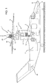
Figure 8 is a side view of a helicopter comprising an anti-torque rotor according to a fourth embodiment of the present invention; -
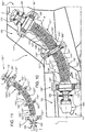
Figure 9 illustrates on a greatly enlarged scale some components of a transmission line of the anti-torque rotor ofFigure 8 ; -
Figure 10 is a partially sectioned side view on a greatly enlarged scale of a helicopter comprising the anti-torque rotor according to the fourth embodiment of the invention, with parts removed for clarity's sake; -
Figure 11 illustrates some components of an anti-torque rotor according to a fifth embodiment of the present invention; -
Figure 12 is a partially sectioned side view on a greatly enlarged scale of a helicopter comprising a rotor according to a sixth embodiment of the present invention, with parts removed for clarity's sake; and -
Figure 13 illustrates some components of an anti-torque rotor according to a seventh embodiment of the present invention. - With reference to
Figures 1 to 7 , 1 indicates an aircraft capable of hovering, in particular a convertiplane. - The
convertiplane 1 essentially comprises: - a
fuselage 2 having an axis A of longitudinal extension; - a pair of half-
wings 3 extending in a cantilever manner from respective parts opposite one another of thefuselage 2 and transversely to the axis A; and - a pair of
nacelles 4 housing respectivepower unit groups 5 and inclinable with respect to thefuselage 2 around an axis G orthogonal to the axis A. - The
fuselage 2 also comprises anose 12 arranged at the front and atail portion 13 that are opposite one another along the axis A. - The half-
wings 3 have respective directions of longitudinal extension parallel to the axis G orthogonal to the axis A. - It should be noted that the term "front", "of tail", "longitudinal", "lateral", "above" and "below" and the like used in this description refer to a normal direction of advancement of the
convertiplane 1 in forward flight. - In the following of the present description a single
power unit group 5 is described, being thepower unit groups 5 identical to each other. - The
power unit group 5 essentially comprises (Figure 2 ) : - a
motor 6 provided with anoutput shaft 7 rotatable around an axis B orthogonal to the axis G; - a
propeller 8 rotatable around an axis C parallel to the axis B; and - a
transmission group 11 interposed between theoutput shaft 7 of themotor 6 and acontrol shaft 10 of thepropeller 8. - In the case illustrated, the axes B, C are parallel to and offset from each other.
- The
convertiplane 1 can be selectively arranged: - in a "helicopter" configuration (visible in
Figure 1 ), in which the axes C of thepropellers 8 are orthogonal to the axis A; and - in an "airplane" configuration (not illustrated), in which the axes C of the
propellers 8 are parallel to the axis A. - The transition of the
convertiplane 1 between the "helicopter" and "airplane" configurations is achieved by inclining thepropellers 8 around the axis G. - In the case illustrated, the
propellers 8 are inclined integrally with thenacelles 4 and with thepower unit groups 5 around the axis G during the aforesaid transition. - The
propeller 8 comprises, in turn: - a joint 20 interposed between the
control shaft 10 and thehub 15; - a
hub 15 having an axis D; and - a plurality of blades constrained to an
element 17 in turn constrained on thehub 15, which is articulated on thecontrol shaft 10 by interposition of a plurality ofelastomeric bearings 19. - The joint 20 is, in the case illustrated, a homokinetic joint configured to transmit only the driving torque.
- The joint 20 is also an elastic flexible joint configured to allow the oscillation of the axis D of the
hub 15 with respect to the axis C of thecontrol shaft 10. - As can be seen in
Figure 4 , thecontrol shaft 10 and thehub 15 have respective axes E, F that are radial and orthogonal with respect to the respective axes C, D. - The joint 20 is configured to allow the oscillation of the axis D around the axis C - and, therefore, of the axis F around the axis E - by a variable angle α comprised between 0 degrees (
Figure 3 ) and, in the case illustrated, +/-12 degrees (Figure 4 ). - Advantageously, the joint 20 is defined by at least one corrugated element made of elastically deformable material; the corrugated element allows the inclination between the axes D, C through elastic deformation of the joint 20 itself.
- In other words, the corrugation of the joint 20 allows to obtain an elastic flexural deformability such as to allow the oscillation of the axis D with respect to the axis C.
- The joint 20 therefore behaves like an articulated joint, although it does not have components that are articulated with one another.
- The term "corrugation" means, in the following of the present description, a continuous succession or continuous in some stretches and periodic succession of annular ridges and grooves around the axis C.
- The corrugation has, in a section containing the axis C (
Figures 4 and5 ): - a longitudinal direction of extension along which the ridges and the grooves are periodically repeated; and
- a transverse direction orthogonal to the direction of extension and along which the ridges and the grooves extend at a distance from each other.
- The maximum distance between two consecutive ridges (grooves) along the longitudinal direction is called pitch p of the corrugation.
- The distance between the ridges and the grooves along the transverse direction is called height h of the corrugation.
- The joint 20 is symmetrical with respect to the axis C.
- With reference to
Figure 2 , the joint 20 essentially comprises: - a pair of
head elements control shaft 10 and to thehub 15; and - an
element 25 interposed between theelements elements - The
elements - The
elements respective corrugations - The
element 25 is tubular and has acorrugation 26 with a longitudinal direction of extension parallel to the axis C and a thickness radial to the axis C. - The
corrugations elements Figure 7 ), respective pluralities ofrings - The
rings corrugations - The
rings 29 are arranged at a first axial distance from thehub 15. - The
rings 30 are arranged at a second axial distance from thehub 15 which is smaller than the aforesaid first axial distance. - The rings 29 (30) are all arranged at the same first (second) axial distance.
- The
corrugations stretches 31, each interposed between arespective ring 29 and therespective rings 30 adjacent thereto. - Each
stretch 31 extends starting from therespective ring 29 at progressively increasing axial and radial distances towards therespective rings 30 adjacent thereto. - The
corrugations - The
rings -
Corrugation 26 comprises respective pluralities ofrings - The
rings corrugation 26. - The
rings 35 are arranged at a first radial distance from the axis C. - The
rings 36 are arranged at a second radial distance from the axis C that is smaller than the aforesaid first radial distance. - The rings 35 (36) are all arranged at the same first (second) radial distance from the axis C.
- The
corrugation 26 has a plurality of connectingstretches 37, each interposed between arespective ring 35 and therespective rings 36 adjacent thereto. - Each
stretch 37 extends starting from therespective ring 35 at progressively increasing axial and radial distances towards the respective rings 36. - The
corrugation 26 has a coil shape in the section parallel to the axis C. - The
corrugation 26 is symmetrical with respect to the axis C. - The
rings - The
corrugations control shaft 10 and to thehub 15. - In particular, the ends 33, 34 extend continuously and uniformly around the respective axes C, D.
- The
corrugations - The
corrugation 26 comprises opposite axial ends 41, 42 opposite one another and connected to respective ends 39, 40 of correspondingcorrugations - In particular, the joint 20 is made of composite material, in particular a fibre-reinforced laminate.
- Alternatively, the joint 20 could be made with different elastic materials such as metal or a combination of several materials.
- In use, the
convertiplane 1 lands and takes off in the "helicopter" configuration and advances in the "airplane" configuration. - In the "helicopter" configuration during hovering or at low speed, the lift necessary to support the
convertiplane 1 is provided by thepropellers 8 arranged with the respective axes C orthogonal to the axes A, E (Figure 1 ). - In the "airplane" configuration, not illustrated, the lift necessary to support the
convertiplane 1 is mostly provided by the half-wings 3. - The
motors 6 drive thepropellers 8 in rotation around the respective axes D. - More specifically, each
motor 6 drives therelative control shaft 10 in rotation around the relative axis C. - The
control shaft 10 drives thehub 15 in rotation around the axis D through the joint 20. - In greater detail, the joint 20 is homokinetic, i.e. the ratio between the rotation speeds of the
control shaft 10 around the axis C and of thehub 15 around the axis D is constant, equal to one in the case illustrated, for each angular position of thecontrol shaft 10 or of thehub 15 relative to the respective axes C, D. - This is obtained in that the ends 33, 34 extend continuously and uniformly around the respective axes B, C. Consequently, no "jerky" movements of the
hub 15 are generated with respect to theshaft 10. - The joint 20 also allows the oscillation of the axis D with respect to the axis C so as to allow the oscillation of the axis E with respect to the axis F equal to the angle α comprised between 0 degrees (
Figure 3 ) and, in the case illustrated, 12 degrees (Figure 4 ), thanks to the presence of thecorrugations - The joint 20 allows said oscillation thanks to its own flexural elastic deformation while it ensures the transmission of torque from the
shaft 10 to thehub 15 through its own torsional rigidity. - This oscillation is due to the fact that the aerodynamic forces acting on the
blades 16 are hardly ever perfectly symmetrical, for example due to a gust of wind or the variation of the cyclic pitch of theblades 16 themselves. - These non-symmetrical forces are also generated during the transition of the
convertiplane 1 between the "airplane" and "helicopter" configurations or due to the gyroscopic forces generated in the event of perturbations acting on theblades 16. - With reference to
Figure 5 , 8' indicates a propeller according to a second embodiment of the present invention. - The propeller 8' is similar to the
propeller 8 and will be described in the following only in so far as it differs from the latter; equal or equivalent parts of thepropellers 8, 8' will be marked, where possible, with the same reference numbers. - The propeller 8' differs from the
propeller 8 in that the joint 20' of thehub 15 does not comprise theelements element 25 only. - The propeller 8' also differs from the
propeller 8 in that the corrugation 26' is helical. - The
rings - The operation of the propeller 8' is similar to that of the
propeller 8 and therefore is not described in detail. - With reference to
Figure 6 ,8 " indicates a propeller according to a third embodiment of the present invention. - The
propeller 8" is similar to thepropeller 8 and will be described in the following only in so far as it differs from the latter; equal or equivalent parts of thepropellers - The
propeller 8" differs from thepropeller 8 in that the joint 20" is formed by a plurality of shapeddisks 52" superimposed on one another parallel to the axis C so as to form a corrugation. - The
discs 52" are connected to one another, in particular by gluing or welding. - Each
disc 52" essentially comprises: - a
respective stretch 53" defining a radially internal end edge of thedisc 52" itself; - a
respective stretch 54" defining a radially external end edge of thedisc 52" itself; and - a
respective stretch 55" that is intermediate between thestretches 53", 54". - The stretches 53", 54", 55" of each
disc 52" are shaped like respective circular crowns. - The
stretch 55" of eachdisc 52" has a greater radial extension than the respective stretches 53", 54". - The stretches 53", 54", 55" are axially offset from one another.
- In particular, the
stretch 55" of eachdisc 52" is at a first axial distance from thestretch 53" of thesame disc 52". Thestretch 54" of eachdisc 52" is at a second axial distance from thestretch 53" of thesame disc 52" which is greater than the first distance. - Each
disc 52" also comprises in the case illustrated: - a
stretch 56" that is curved and radially interposed between the relative stretches 53", 55"; and - a
stretch 57" that is curved and radially interposed between the relative stretches 55", 54". - The joint 20" comprises a plurality of
pairs 58" ofdiscs 52". - The stretches 53" of the
discs 52" of eachpair 58" are connected to one another. - The stretches 54" of
discs 52" ofpairs 58" adjacent to each other are connected to one another. - In particular, the
discs 52" of eachpair 58" extend at a progressively increasing axial distance, proceeding from the respective stretches 53" up to the corresponding stretches 54". - The stretches 53", 54", 55" of the
discs 52" define acorrugation 60". - The
corrugation 60" has a longitudinal direction of extension parallel to the axis C and a thickness radial to the axis C. - More precisely, the
stretches 55" connected to one another ofadjacent discs 52" ofconsecutive pairs 58" define the ridges of thecorrugation 60". - The stretches 53" connected to one another of
discs 52" of thesame pair 58" define the bellies of thecorrugation 60". - The
corrugation 60" has an h/p ratio greater than 1. The solution illustrated inFigure 6 can be advantageous when particularly high h/p ratios are required for which it is not practical to corrugate a laminate in a single piece. - The operation of the
propeller 8" is similar to that of thepropeller 8 and is therefore not described in detail. - With reference to
Figures 8 to 10 , 100 indicates a helicopter comprising an anti-torque rotor 106'" according to a fourth embodiment of the invention. - The
helicopter 100 essentially comprises: - a
fuselage 102; - one or
more turbines 105; - a
main rotor 103 placed at a top of thefuselage 105 and rotatable around a first axis; and - the
anti-torque rotor 106"', which is placed at a tail end of thefuselage 102 and rotatable around its own axis H transverse to the axis of therotor 103. - The
helicopter 100 further comprises atransmission group 111, which transmits the motion from theturbines 105 to themain rotor 103 and to therotor 106". - The
transmission assembly 111 is illustrated limitedly to anauxiliary output shaft 108 rotatable around an axis I and operatively connected to theanti-torque rotor 106, as will be described in greater detail below. - The rotor 106'" generates a thrust, which brings about a contrasting torque on the
fuselage 102. - Said contrasting torque is oriented in the opposite direction to the torque exerted by the
rotor 103 on thefuselage 102. - According to the thrust value generated by the
rotor 106"', it is therefore possible to orient thehelicopter 100 according to a desired yaw angle, or to adjust the aforesaid yaw angle according to the manoeuvre to be performed. - In greater detail, the rotor 106'" essentially comprises:
- a
control shaft 112 rotatable around an axis J and operatively connected to theshaft 108; and - a plurality of
blades 109, in the case illustrated two in number, which are rotatable around the axis H and extend in a cantilever manner along respective axes transversal to the axis J. - The anti-torque rotor 106'" also comprises a joint 20'" interposed between the
shaft 112 and theshaft 108. - The joint 20'" is similar to the joint 20 and will be described below only in so far as it differs from the latter; equal or equivalent parts of the
joints 20, 20'" will be marked, where possible, with the same reference numbers. - The joint 20'" is configured to transmit a torque between the
shaft 108 and theshaft 112 having respective axes I, J inclined with respect to each other by a constant angle β. - The joint 20'" is axial-symmetrical along a curved axis K and joining the axes I, J.
- The joint 20'" comprises (
Figures 8 to 10 ) essentially: - a pair of
elements 120"', 121'" connected to each other and connected respectively to theshaft 112 and theshaft 108; and - a plurality of
support elements 115"', 116"', 117"', three in the case illustrated, interposed between the joint 20'" and thefuselage 102 and adapted to support the joint 20'" allowing its elastic rotation around the axis K. - The
helicopter 100 also comprises (Figure 12 ): - a joint 200 interposed between the
shaft 108 and theelement 120"'; and - a joint 201 interposed between the
element 121"' and theshaft 112. - In greater detail, the
elements 120"', 121"' definerespective corrugations 124"', 125"'. - Each
corrugation 124"', 125'" has a direction of longitudinal extension that is curved and parallel to the axis K and a thickness along a direction orthogonal to the axis K. - Each
corrugation 124"', 125'" comprises respective pluralities ofrings 126"', 127"'. - The
rings 126"', 127'" are alternated with each other parallel to the curvilinear axis K and define respective radial ends opposite one another of therespective corrugation 124"', 125"'. - The rings 126'" are arranged at a first radial distance from the axis K.
- The
rings 127"' are arranged at a second radial distance from the axis K that is smaller than the aforesaid first radial distance. - The rings 126'" (127"') are all arranged at the same first (second) radial distance from the axis K.
- The
corrugation 124"', 125'" has a plurality of connectingstretches 128"' each interposed between a respective ring 126'" and the respective rings 127'" adjacent thereto. - Each stretch 128'" extends starting from the respective ring 126'" at progressively increasing axial and radial distances towards the
respective rings 127"'. - The
corrugation 124"', 125'" has a coil shape in a section obtained in a plane parallel to the axis K, in the case illustrated. - The
corrugation 124"', 125'" is symmetrical with respect to the axis K. - The
rings 126"', 127'" lie on respective planes orthogonal to the axis K. - The
elements 120"', 121'" ' compriserespective flanges 129"'. - The support element 115'" comprises a double-
row rolling bearing 130"', in the case illustrated. - The bearing 130'" essentially comprises:
- an inner ring that is rotatable integrally with the joint 200 and with a
flange 129"' of theelement 120"'; and - an outer ring fixed to the
fuselage 102. - The support element 116'" comprises a rolling bearing 131'" with tapered rollers, in the case illustrated.
- The bearing 131'" essentially comprises:
- an inner ring that is rotatable integrally with the
other flange 129"' of the element 120'" and with aflange 129"' of theelement 121"'; and - an outer ring fixed to the
fuselage 102. - The support element 117'" comprises a rolling
bearing 132"', with tapered rollers in the case illustrated. - The bearing 132'" essentially comprises:
- an inner ring that is rotatable integrally with the
other flange 129"' of theelement 121"' and with the joint 201; and - an outer ring fixed to the
fuselage 102. - In use, the
turbines 105 drive thetransmission group 111. - The
transmission group 111 drives in rotation themain rotor 103 and theauxiliary shaft 108 around the axis I. - The
auxiliary shaft 108 drives in rotation theanti-torque rotor 106 through theshaft 108 that is rotatable around the axis I and through the joint 20"'. - In greater detail, the
elements 120"', 121'" ' of the joint 20'" allow the misalignment between the axes I, J by a fixed angle (Figure 10 ). - The joint 20'" allows said misalignment thanks to its own elastic flexural deformation in the plane containing the axes I, J, K.
- More precisely, the joint 20'" deforms elastically flexurally in such a way as to keep the angle between the axes I, J constant, thanks to the presence of the
corrugations 124"', 125'" which provide torsional rigidity and at the same time flexural flexibility and to the fact that it is made of a fibre-reinforced composite laminate. - With reference to
Figure 11 , 106"" indicates an anti-torque rotor according to a fifth embodiment of the invention. - The
rotor 106"" is similar to therotor 106"' and will be described in the following only in so far as it differs from the latter; equal or equivalent parts of therotors 106"', 106"" will be marked, where possible, with the same reference numbers. - The
rotor 106"" differs from the rotor 106'" in that it comprises threeelements 120"", 121"", 122'''' withrespective corrugations 124"", 125"", 123"", and in that it comprises foursupport elements 115"", 116"", 117"", 118"" withrespective bearings 130"", 131"", 132"", 133"". - The operation of the
rotor 106"" is similar to that of the rotor 106'" and is therefore not described in detail. - With reference to
Figure 12 , 106"" indicates an anti-torque rotor according to a sixth embodiment of the invention. - The
rotor 106""' is similar to the rotor 106'" and will be described in the following only in so far as it differs from the latter; equal or equivalent parts of therotors 106""', 106'" will be marked, where possible, with the same reference numbers. - The
rotor 106""' differs from the rotor 106'" in that thecorrugations 124""', 125""' are helical with respect to the axis K and the rings 126'"", 127""' lie on respective planes orthogonal to the axis K. - With reference to
Figure 13 , 106""" indicates an anti-torque rotor according to a seventh embodiment of the invention. - The
rotor 106""" is similar to therotor 106"" and will be described below only in so far as it differs from the latter; equal or equivalent parts of therotors 106""", 106"" will be marked, where possible, with the same reference numbers. - The
rotor 106""" differs from therotor 106"" in that thecorrugations 124"', 125"', 123'" are helical with respect to the axis K and therings 126"', 127"' lie on respective planes orthogonal to the axis K. - In a further embodiment not illustrated, the
elements 120"', 121"'; 120"", 121"" of the joint 20'" could be made of metal, for example, titanium and optionally coated with a jacket of fibreglass or other fibre-reinforced material. - The
aforesaid elements 120"', 121"'; 120"", 121"" of said further embodiment can be also easily made by means of additive manufacturing technology. In this way, problems in removing the internal spindle that would be necessary with other methods for manufacturing composite products are avoided. - The advantages the present invention allows to obtain are evident from the characteristics of the
propeller convertiplane 1 and the anti-torque rotor 106'" , 106"", 106""', 106""" of thehelicopter 100 according to the present invention. - In particular, the
propeller anti-torque rotors 106"', 106"", 106"""" comprise respectively thejoints respective corrugations - Said
corrugations joints - In other words, the
corrugations - The ends 33, 34 extend continuously and uniformly around the respective axes C, D, K. This allows to guarantee the homokinetic operation of the joint 20, 20', 20", 20"'.
- It is important to underline that these characteristics are obtained without requiring the use of numerous components articulated with one another unlike the solutions of the known type and discussed in the introductory part of the present description, with evident advantages of reduction in weight and construction simplification.
- In this way, the joint 20, 20', 20" allows the motion to be transmitted between the
control shaft 10 and thehub 15 enabling a variable oscillation between the axes E, F, in the case illustrated between 0 and 12 degrees during operation of theconvertiplane 1. - In greater detail, the
corrugations control shaft 10 to the hub 15 - together with a high flexural flexibility in the planes containing the axes C, D and an axial flexibility, which allows the aforesaid oscillation between the axes C, D. - The joint 20'" allows the motion to be transmitted between the
shafts - In other words, the joint 20'" allows the bevel gear usually provided between the
aforesaid shafts anti-torque rotor 106"', 106"", 106""', 106""" to be replaced effectively and with weight/cost reductions. - The helical conformation of the
corrugations 23, 26'; 124""', 125""'; 124""", 125""", 123""" enable raising the torsional resistance in one direction. This is particularly advantageous in that the maximum torque acting on thejoints 20, 20'; 20", 20'" is always directed in one direction. - The
elements 120"', 121"'; 120"", 121"" of the joint 20'" could be, in a further embodiment, made of metal, for example, titanium and coated with a jacket of fibreglass or fibre-reinforced composite material. In this way, a catastrophic failure of the joint 20'" would be avoided in the event that a crack was generated that would lead to failure. - Finally, the joint 20" formed by
discs 52" allows to obtain particularly high h/p ratios thanks to the fact that it does not entail problems in removing the internal spindle that would be necessary with other manufacturing methods. - Said characteristics of the joint 20, 20', 20", 20"' can be optimized by suitably selecting the lamination sequence of the fibre-reinforced material of the
elements - It is clear that modifications and variations may be made to the
propeller convertiplane 1 and to theanti-torque rotor 106"', 106"", 106""', 106""" of thehelicopter 100 described and illustrated herein without thereby departing from the scope of protection defined by the claims. - In particular, the
corrugations - The anti-torque rotor 106'" could comprise the joint 20" instead of the joint 20'" interposed between the
shaft 112 and theshaft 108. - One or more of the
corrugations
Claims (15)
- A rotor (8, 8', 8", 106"', 106"", 106""', 106""') for an aircraft (1, 100), comprising:- an input shaft (10, 108) rotatable around a first axis (C, I);- an output member (15, 112) rotatable around a second axis (D, J);- a coupling element (20, 20', 20", 20"') functionally interposed between said input shaft (10, 108) and said output member (15, 112) and adapted to transmit the motion from said input shaft (10, 108) to said output member (15, 112);
said coupling element (20, 20', 20", 20"') being configured to allow, in use, an inclination by a constant or variable angle between the respective said first axis (C, I) and second axis (D, J);
characterized in that said coupling element (20, 20', 20", 20"') comprises at least a first corrugated element (21, 22, 25, 120"', 121"'; 120"", 121"", 122"") made of an elastically deformable material;
said first corrugated element (21, 22, 25, 52", 120"', 121"', 120"", 121"", 122"") allowing said inclination through elastic deformation. - The rotor according to claim 1, characterized in that said coupling element (20, 20', 20", 20"') is homokinetic; and/or
characterized in that said coupling element (20, 20', 20", 20"') is torsionally rigid in a plane orthogonal to said first and second axis (C, I; D, J) and flexurally yielding in at least one plane parallel to said first and second axis (C, I; D, J). - The rotor according to claim 1 or 2, characterized in that said first corrugated element (25, 120"', 121"', 120"", 121"", 122"") is axial-symmetrical around a third axis (C; K) and has a first corrugation (26, 26', 124"', 125"', 124"", 125"", 123"", 124""', 125"", 124""", 125""", 123""");
said first corrugation (26, 26', 124"', 125"', 124"", 125"", 123"") having a direction of extension parallel to said third axis (C, K) and a radial thickness with respect to said third axis (C, K). - The rotor according to claim 3, characterized in that said first corrugation (26, 26', 124"', 125"', 124"", 125"", 123"") comprises at least a first ring (35) radially external with respect to said third axis (C, K) and axially interposed between two second rings (36) radially internal with respect to the third axis (C, K) itself;
said first ring (35) and second rings (36) being defined by a single said first corrugated element (25, 120"', 121"', 120"", 121"", 122""). - The rotor according to any one of claims 2 to 4, characterized in that it comprises at least a second corrugated element (21, 22);
said second corrugated element (21, 22) being discoidal and comprising a second corrugation (23, 24) with a direction of extension radial to said first axis (C) and a parallel thickness with respect to said first axis (C). - The rotor according to any one of claims 3 to 5, characterized in that said first corrugation (26', 124""', 125""', 124""", 125""", 123""") is helical; and/or characterized in that said first and third axis (C) coincide with each other.
- The rotor according to any one of the preceding claims, characterized in that said coupling element (20") comprises a plurality of axially corrugated discs (52") superimposed on one another and connected to one another;
said discs (52'') comprising first radially internal ends (53") and second radially external ends (54") axially offset with respect to said first radially internal ends (53"). - The rotor according to claim 7, characterized in that each said disc (52") comprises a stretch (55") interposed radially and axially between the respective said first and second end (53", 54").
- The rotor according to claim 7 or 8, characterized in that said discs (52") axially consecutive to one another comprise respective said first radially internal ends (53") connected to one another and/or respective second radially external ends (54") connected to one another.
- The rotor according to any one of the preceding claims, characterized in that said at least one first corrugated element (21, 22, 25, 120"', 121"', 120"", 121"", 122"") is made of a fibre-reinforced composite material.
- The rotor according to any one of claims 2 to 10, characterized in that said coupling element (20, 20', 20", 20"') comprises a first and a second end edge (33, 34) connected respectively to said input shaft (10, 108) and said output member (15, 112);
said first and second end edges (33, 34) being circular and circumferentially continuous so as to make said coupling element (20, 20', 20", 20"') homokinetic. - The rotor according to any one of claims 1 to 9 or 11, characterized in that said at least one first corrugated element (21, 22, 25, 120"', 121"', 120"", 121"", 122"") is made of a metallic material coated with a jacket of fibreglass.
- A convertiplane (1) characterized in that it comprises:- a fuselage (2) extending along a fourth axis (A);- a pair of half-wings (3) extending from respective side bands opposite one another of said fuselage (2);- a pair of rotors (8, 8', 8") according to any one of the preceding claims and associated with said half-wings (3, 3'), rotatable around respective second axes (D) and inclinable around a fifth axis (G) orthogonal to said first and fourth axis (B, A) between:a first position in which said second axes (D) are parallel to said fourth axis (A), which position is reached when said convertiplane (1) is, in use, in an airplane configuration; anda second position in which said second axes (D) are orthogonal to said fourth axis (A), which position is reached when said convertiplane (1) is, in use, in a helicopter configuration;said input shaft (10) being a control shaft of the respective said propeller (8, 8', 8") rotatable around the respective said first axis (C);said output member (15) being a hub (15) on which a plurality of respective blades (16) are articulated and rotatable around a respective second axis (D);said coupling element (20) is configured to allow, in use, said variable oscillation angle (α) between said first and second axes (C, D).
- A helicopter (100) comprising:- a fuselage (102);- a motor member (105);- a transmission group (111); and- an anti-torque rotor (106''', 106"", 106""', 106""") defined by a rotor according to any one of claims 1 to 12 and driven by said transmission group (111);said anti-torque rotor (106"', 106"", 106""', 106""") comprising:- a first shaft (108) driven by said transmission group (111) and defining said input shaft (108) and rotatable around said first axis (I);- a second shaft (112) inclined with respect to said first shaft (108) and defining said output member (112) and rotatable around said second axis (J) fixed with respect to said fuselage (102); and- a plurality of blades (109) articulated on said second shaft (112);said first and second axes (I, J) being inclined with respect to each other by a constant angle.
- The helicopter according to claim 14, characterized in that said coupling element (20"') extends along a sixth curvilinear axis (K) extending between said first and second axis (I, J).
Priority Applications (5)
| Application Number | Priority Date | Filing Date | Title |
|---|---|---|---|
| EP20182377.0A EP3929077B1 (en) | 2020-06-25 | 2020-06-25 | Rotor for an aircraft capable of hovering |
| US18/007,579 US12434824B2 (en) | 2020-06-25 | 2021-05-26 | Rotor for an aircraft capable of hovering |
| KR1020227046310A KR20230029698A (en) | 2020-06-25 | 2021-05-26 | Rotor for aircraft capable of hovering |
| PCT/IB2021/054604 WO2021260459A1 (en) | 2020-06-25 | 2021-05-26 | Rotor for an aircraft capable of hovering |
| CN202180040901.1A CN115916641B (en) | 2020-06-25 | 2021-05-26 | Rotor for an aircraft capable of hovering |
Applications Claiming Priority (1)
| Application Number | Priority Date | Filing Date | Title |
|---|---|---|---|
| EP20182377.0A EP3929077B1 (en) | 2020-06-25 | 2020-06-25 | Rotor for an aircraft capable of hovering |
Publications (2)
| Publication Number | Publication Date |
|---|---|
| EP3929077A1 true EP3929077A1 (en) | 2021-12-29 |
| EP3929077B1 EP3929077B1 (en) | 2022-08-03 |
Family
ID=72147866
Family Applications (1)
| Application Number | Title | Priority Date | Filing Date |
|---|---|---|---|
| EP20182377.0A Active EP3929077B1 (en) | 2020-06-25 | 2020-06-25 | Rotor for an aircraft capable of hovering |
Country Status (5)
| Country | Link |
|---|---|
| US (1) | US12434824B2 (en) |
| EP (1) | EP3929077B1 (en) |
| KR (1) | KR20230029698A (en) |
| CN (1) | CN115916641B (en) |
| WO (1) | WO2021260459A1 (en) |
Families Citing this family (1)
| Publication number | Priority date | Publication date | Assignee | Title |
|---|---|---|---|---|
| CN115675845B (en) * | 2022-11-22 | 2025-07-08 | 佛山大学 | Multi-gap flexible attitude adjusting mechanism for rotor craft and rotor craft |
Citations (10)
| Publication number | Priority date | Publication date | Assignee | Title |
|---|---|---|---|---|
| GB2082730A (en) * | 1980-08-25 | 1982-03-10 | Lord Corp | Improvements relating to flexible couplings |
| GB2113349A (en) * | 1982-01-14 | 1983-08-03 | Gordon Howard Townend | Universal joints |
| EP0276945B1 (en) | 1987-01-30 | 1993-12-29 | Lord Corporation | Link-type rotary coupling |
| EP1088755B1 (en) | 1999-10-01 | 2003-05-21 | Bell Helicopter Textron Inc. | Prop rotor hub |
| EP1346910A1 (en) * | 2002-03-20 | 2003-09-24 | Eurocopter | Rotor for a rotary wing aircraft having constant velocity drive |
| WO2010128378A2 (en) * | 2009-05-06 | 2010-11-11 | K4A S.R.L. | Constant velocity joint for helicopter rotors |
| WO2014203671A1 (en) * | 2013-06-17 | 2014-12-24 | 株式会社安川電機 | Joint |
| US20180023631A1 (en) * | 2016-07-19 | 2018-01-25 | Goodrich Corporation | Flexible couplings for mechanical power transmissions |
| US10364848B2 (en) * | 2016-06-23 | 2019-07-30 | Bell Helicopter Textron, Inc. | Helical drive coupling |
| CN110617277A (en) * | 2018-06-19 | 2019-12-27 | 中国船舶重工集团公司第七一一研究所 | Elastic coupling with composite material membrane disc |
Family Cites Families (12)
| Publication number | Priority date | Publication date | Assignee | Title |
|---|---|---|---|---|
| US1501187A (en) * | 1921-09-03 | 1924-07-15 | Charles L Rayfield | Flexible coupling |
| US2870617A (en) * | 1954-04-26 | 1959-01-27 | Melville F Peters | Control of torque and fluid flow in sealed drives |
| US3055195A (en) * | 1961-03-28 | 1962-09-25 | Gordon L Olson | Fabricated flexible coupling |
| US5054716A (en) * | 1989-10-16 | 1991-10-08 | Bell Helicopter Textron Inc. | Drive system for tiltrotor aircraft |
| US5360376A (en) * | 1993-01-13 | 1994-11-01 | United Technologies Corporation | Quick release disconnect coupling device for drive shaft segments |
| US5564982A (en) * | 1994-05-04 | 1996-10-15 | Gipson; Alvin W. | Flexible coupling with quick-disconnect coupling hubs |
| DE19812223A1 (en) * | 1998-03-19 | 1999-09-23 | Mayr Christian Gmbh & Co Kg | Corrugated tube transmits torque from one shaft to another |
| FR2837784B1 (en) * | 2002-03-28 | 2004-05-28 | Eurocopter France | CELLULAR DRIVE ROTOR ROTOR WITH TORQUE SHARING DIFFERENTIAL |
| US10059438B2 (en) * | 2011-12-26 | 2018-08-28 | Textron Innovations Inc. | Hub assembly with grease lubricated roller bearing and tension-torsion strap |
| US10494089B2 (en) * | 2014-05-21 | 2019-12-03 | Sikorsky Aircraft Corporation | Drive shaft system hanger bearing |
| US9764829B1 (en) * | 2015-06-09 | 2017-09-19 | Amazon Technologies, Inc. | Multirotor aircraft with enhanced yaw control |
| EP3342707B1 (en) * | 2016-12-30 | 2019-03-06 | Leonardo S.P.A. | Aircraft capable of hovering with main rotor |
-
2020
- 2020-06-25 EP EP20182377.0A patent/EP3929077B1/en active Active
-
2021
- 2021-05-26 US US18/007,579 patent/US12434824B2/en active Active
- 2021-05-26 KR KR1020227046310A patent/KR20230029698A/en active Pending
- 2021-05-26 CN CN202180040901.1A patent/CN115916641B/en active Active
- 2021-05-26 WO PCT/IB2021/054604 patent/WO2021260459A1/en not_active Ceased
Patent Citations (10)
| Publication number | Priority date | Publication date | Assignee | Title |
|---|---|---|---|---|
| GB2082730A (en) * | 1980-08-25 | 1982-03-10 | Lord Corp | Improvements relating to flexible couplings |
| GB2113349A (en) * | 1982-01-14 | 1983-08-03 | Gordon Howard Townend | Universal joints |
| EP0276945B1 (en) | 1987-01-30 | 1993-12-29 | Lord Corporation | Link-type rotary coupling |
| EP1088755B1 (en) | 1999-10-01 | 2003-05-21 | Bell Helicopter Textron Inc. | Prop rotor hub |
| EP1346910A1 (en) * | 2002-03-20 | 2003-09-24 | Eurocopter | Rotor for a rotary wing aircraft having constant velocity drive |
| WO2010128378A2 (en) * | 2009-05-06 | 2010-11-11 | K4A S.R.L. | Constant velocity joint for helicopter rotors |
| WO2014203671A1 (en) * | 2013-06-17 | 2014-12-24 | 株式会社安川電機 | Joint |
| US10364848B2 (en) * | 2016-06-23 | 2019-07-30 | Bell Helicopter Textron, Inc. | Helical drive coupling |
| US20180023631A1 (en) * | 2016-07-19 | 2018-01-25 | Goodrich Corporation | Flexible couplings for mechanical power transmissions |
| CN110617277A (en) * | 2018-06-19 | 2019-12-27 | 中国船舶重工集团公司第七一一研究所 | Elastic coupling with composite material membrane disc |
Also Published As
| Publication number | Publication date |
|---|---|
| WO2021260459A1 (en) | 2021-12-30 |
| US12434824B2 (en) | 2025-10-07 |
| CN115916641B (en) | 2025-08-26 |
| KR20230029698A (en) | 2023-03-03 |
| US20230234701A1 (en) | 2023-07-27 |
| CN115916641A (en) | 2023-04-04 |
| EP3929077B1 (en) | 2022-08-03 |
Similar Documents
| Publication | Publication Date | Title |
|---|---|---|
| EP2832640B1 (en) | Composite flexure for tiltrotor rotor system | |
| JP2768826B2 (en) | Duct fan and pitch controller for tail rotor of rotary wing aircraft | |
| CA2113179C (en) | Ducted tail rotor for rotary wing aircraft providing torque reaction and yaw attitude control | |
| US20030222171A1 (en) | Constant velocity drive rotary-wing aircraft rotor with torque splitting differential | |
| EP3323720B1 (en) | Proprotor systems for tiltrotor aircraft | |
| EP2868576B1 (en) | Drive link for tiltrotor rotor system | |
| US11493121B2 (en) | Gear systems having bearing flexure mounted thrust bearings | |
| EP2907747A1 (en) | Cyclic pitch actuation system for counter-rotating propellers | |
| EP0449531B1 (en) | Rotors | |
| US12434824B2 (en) | Rotor for an aircraft capable of hovering | |
| US6439849B1 (en) | Dual trunnion hub-to-mast assembly | |
| US10618630B2 (en) | Flex beam for rotor assembly | |
| US12054246B2 (en) | Helicopter | |
| EP3137377B1 (en) | Radially compliant quill shaft | |
| US12181038B2 (en) | Aircraft capable of hovering | |
| EP3434588B1 (en) | Rotor hub assembly with universal joint | |
| WO2004045948A1 (en) | Rotary blade |
Legal Events
| Date | Code | Title | Description |
|---|---|---|---|
| STAA | Information on the status of an ep patent application or granted ep patent |
Free format text: STATUS: EXAMINATION IS IN PROGRESS |
|
| PUAI | Public reference made under article 153(3) epc to a published international application that has entered the european phase |
Free format text: ORIGINAL CODE: 0009012 |
|
| 17P | Request for examination filed |
Effective date: 20201215 |
|
| AK | Designated contracting states |
Kind code of ref document: A1 Designated state(s): AL AT BE BG CH CY CZ DE DK EE ES FI FR GB GR HR HU IE IS IT LI LT LU LV MC MK MT NL NO PL PT RO RS SE SI SK SM TR |
|
| B565 | Issuance of search results under rule 164(2) epc |
Effective date: 20201203 |
|
| GRAP | Despatch of communication of intention to grant a patent |
Free format text: ORIGINAL CODE: EPIDOSNIGR1 |
|
| STAA | Information on the status of an ep patent application or granted ep patent |
Free format text: STATUS: GRANT OF PATENT IS INTENDED |
|
| RIC1 | Information provided on ipc code assigned before grant |
Ipc: B64C 27/22 20060101ALN20220110BHEP Ipc: F16D 3/50 20060101ALI20220110BHEP Ipc: F16D 3/74 20060101ALI20220110BHEP Ipc: F16D 3/72 20060101ALI20220110BHEP Ipc: F16D 3/62 20060101ALI20220110BHEP Ipc: F16D 21/02 20060101ALI20220110BHEP Ipc: F16D 3/70 20060101ALI20220110BHEP Ipc: B64C 27/82 20060101ALI20220110BHEP Ipc: B64C 27/12 20060101AFI20220110BHEP |
|
| INTG | Intention to grant announced |
Effective date: 20220126 |
|
| GRAS | Grant fee paid |
Free format text: ORIGINAL CODE: EPIDOSNIGR3 |
|
| GRAA | (expected) grant |
Free format text: ORIGINAL CODE: 0009210 |
|
| STAA | Information on the status of an ep patent application or granted ep patent |
Free format text: STATUS: THE PATENT HAS BEEN GRANTED |
|
| AK | Designated contracting states |
Kind code of ref document: B1 Designated state(s): AL AT BE BG CH CY CZ DE DK EE ES FI FR GB GR HR HU IE IS IT LI LT LU LV MC MK MT NL NO PL PT RO RS SE SI SK SM TR |
|
| REG | Reference to a national code |
Ref country code: AT Ref legal event code: REF Ref document number: 1508552 Country of ref document: AT Kind code of ref document: T Effective date: 20220815 Ref country code: CH Ref legal event code: EP |
|
| REG | Reference to a national code |
Ref country code: DE Ref legal event code: R096 Ref document number: 602020004309 Country of ref document: DE |
|
| REG | Reference to a national code |
Ref country code: IE Ref legal event code: FG4D |
|
| RAP2 | Party data changed (patent owner data changed or rights of a patent transferred) |
Owner name: LEONARDO S.P.A. |
|
| REG | Reference to a national code |
Ref country code: DE Ref legal event code: R081 Ref document number: 602020004309 Country of ref document: DE Owner name: LEONARDO S.P.A., IT Free format text: FORMER OWNERS: LEONARDO S.P.A., ROMA, IT; POLITECNICO DI MILANO, MILANO, IT |
|
| REG | Reference to a national code |
Ref country code: LT Ref legal event code: MG9D |
|
| REG | Reference to a national code |
Ref country code: NL Ref legal event code: MP Effective date: 20220803 |
|
| PG25 | Lapsed in a contracting state [announced via postgrant information from national office to epo] |
Ref country code: SE Free format text: LAPSE BECAUSE OF FAILURE TO SUBMIT A TRANSLATION OF THE DESCRIPTION OR TO PAY THE FEE WITHIN THE PRESCRIBED TIME-LIMIT Effective date: 20220803 Ref country code: RS Free format text: LAPSE BECAUSE OF FAILURE TO SUBMIT A TRANSLATION OF THE DESCRIPTION OR TO PAY THE FEE WITHIN THE PRESCRIBED TIME-LIMIT Effective date: 20220803 Ref country code: PT Free format text: LAPSE BECAUSE OF FAILURE TO SUBMIT A TRANSLATION OF THE DESCRIPTION OR TO PAY THE FEE WITHIN THE PRESCRIBED TIME-LIMIT Effective date: 20221205 Ref country code: NO Free format text: LAPSE BECAUSE OF FAILURE TO SUBMIT A TRANSLATION OF THE DESCRIPTION OR TO PAY THE FEE WITHIN THE PRESCRIBED TIME-LIMIT Effective date: 20221103 Ref country code: NL Free format text: LAPSE BECAUSE OF FAILURE TO SUBMIT A TRANSLATION OF THE DESCRIPTION OR TO PAY THE FEE WITHIN THE PRESCRIBED TIME-LIMIT Effective date: 20220803 Ref country code: LV Free format text: LAPSE BECAUSE OF FAILURE TO SUBMIT A TRANSLATION OF THE DESCRIPTION OR TO PAY THE FEE WITHIN THE PRESCRIBED TIME-LIMIT Effective date: 20220803 Ref country code: LT Free format text: LAPSE BECAUSE OF FAILURE TO SUBMIT A TRANSLATION OF THE DESCRIPTION OR TO PAY THE FEE WITHIN THE PRESCRIBED TIME-LIMIT Effective date: 20220803 Ref country code: FI Free format text: LAPSE BECAUSE OF FAILURE TO SUBMIT A TRANSLATION OF THE DESCRIPTION OR TO PAY THE FEE WITHIN THE PRESCRIBED TIME-LIMIT Effective date: 20220803 Ref country code: ES Free format text: LAPSE BECAUSE OF FAILURE TO SUBMIT A TRANSLATION OF THE DESCRIPTION OR TO PAY THE FEE WITHIN THE PRESCRIBED TIME-LIMIT Effective date: 20220803 |
|
| REG | Reference to a national code |
Ref country code: AT Ref legal event code: MK05 Ref document number: 1508552 Country of ref document: AT Kind code of ref document: T Effective date: 20220803 |
|
| PG25 | Lapsed in a contracting state [announced via postgrant information from national office to epo] |
Ref country code: PL Free format text: LAPSE BECAUSE OF FAILURE TO SUBMIT A TRANSLATION OF THE DESCRIPTION OR TO PAY THE FEE WITHIN THE PRESCRIBED TIME-LIMIT Effective date: 20220803 Ref country code: IS Free format text: LAPSE BECAUSE OF FAILURE TO SUBMIT A TRANSLATION OF THE DESCRIPTION OR TO PAY THE FEE WITHIN THE PRESCRIBED TIME-LIMIT Effective date: 20221203 Ref country code: HR Free format text: LAPSE BECAUSE OF FAILURE TO SUBMIT A TRANSLATION OF THE DESCRIPTION OR TO PAY THE FEE WITHIN THE PRESCRIBED TIME-LIMIT Effective date: 20220803 Ref country code: GR Free format text: LAPSE BECAUSE OF FAILURE TO SUBMIT A TRANSLATION OF THE DESCRIPTION OR TO PAY THE FEE WITHIN THE PRESCRIBED TIME-LIMIT Effective date: 20221104 |
|
| PG25 | Lapsed in a contracting state [announced via postgrant information from national office to epo] |
Ref country code: SM Free format text: LAPSE BECAUSE OF FAILURE TO SUBMIT A TRANSLATION OF THE DESCRIPTION OR TO PAY THE FEE WITHIN THE PRESCRIBED TIME-LIMIT Effective date: 20220803 Ref country code: RO Free format text: LAPSE BECAUSE OF FAILURE TO SUBMIT A TRANSLATION OF THE DESCRIPTION OR TO PAY THE FEE WITHIN THE PRESCRIBED TIME-LIMIT Effective date: 20220803 Ref country code: DK Free format text: LAPSE BECAUSE OF FAILURE TO SUBMIT A TRANSLATION OF THE DESCRIPTION OR TO PAY THE FEE WITHIN THE PRESCRIBED TIME-LIMIT Effective date: 20220803 Ref country code: CZ Free format text: LAPSE BECAUSE OF FAILURE TO SUBMIT A TRANSLATION OF THE DESCRIPTION OR TO PAY THE FEE WITHIN THE PRESCRIBED TIME-LIMIT Effective date: 20220803 Ref country code: AT Free format text: LAPSE BECAUSE OF FAILURE TO SUBMIT A TRANSLATION OF THE DESCRIPTION OR TO PAY THE FEE WITHIN THE PRESCRIBED TIME-LIMIT Effective date: 20220803 |
|
| REG | Reference to a national code |
Ref country code: DE Ref legal event code: R097 Ref document number: 602020004309 Country of ref document: DE |
|
| PG25 | Lapsed in a contracting state [announced via postgrant information from national office to epo] |
Ref country code: SK Free format text: LAPSE BECAUSE OF FAILURE TO SUBMIT A TRANSLATION OF THE DESCRIPTION OR TO PAY THE FEE WITHIN THE PRESCRIBED TIME-LIMIT Effective date: 20220803 Ref country code: EE Free format text: LAPSE BECAUSE OF FAILURE TO SUBMIT A TRANSLATION OF THE DESCRIPTION OR TO PAY THE FEE WITHIN THE PRESCRIBED TIME-LIMIT Effective date: 20220803 |
|
| PLBE | No opposition filed within time limit |
Free format text: ORIGINAL CODE: 0009261 |
|
| STAA | Information on the status of an ep patent application or granted ep patent |
Free format text: STATUS: NO OPPOSITION FILED WITHIN TIME LIMIT |
|
| PG25 | Lapsed in a contracting state [announced via postgrant information from national office to epo] |
Ref country code: AL Free format text: LAPSE BECAUSE OF FAILURE TO SUBMIT A TRANSLATION OF THE DESCRIPTION OR TO PAY THE FEE WITHIN THE PRESCRIBED TIME-LIMIT Effective date: 20220803 |
|
| 26N | No opposition filed |
Effective date: 20230504 |
|
| P01 | Opt-out of the competence of the unified patent court (upc) registered |
Effective date: 20231005 |
|
| PG25 | Lapsed in a contracting state [announced via postgrant information from national office to epo] |
Ref country code: MC Free format text: LAPSE BECAUSE OF FAILURE TO SUBMIT A TRANSLATION OF THE DESCRIPTION OR TO PAY THE FEE WITHIN THE PRESCRIBED TIME-LIMIT Effective date: 20220803 |
|
| PG25 | Lapsed in a contracting state [announced via postgrant information from national office to epo] |
Ref country code: MC Free format text: LAPSE BECAUSE OF FAILURE TO SUBMIT A TRANSLATION OF THE DESCRIPTION OR TO PAY THE FEE WITHIN THE PRESCRIBED TIME-LIMIT Effective date: 20220803 |
|
| REG | Reference to a national code |
Ref country code: CH Ref legal event code: PL |
|
| REG | Reference to a national code |
Ref country code: BE Ref legal event code: MM Effective date: 20230630 |
|
| PG25 | Lapsed in a contracting state [announced via postgrant information from national office to epo] |
Ref country code: LU Free format text: LAPSE BECAUSE OF NON-PAYMENT OF DUE FEES Effective date: 20230625 |
|
| REG | Reference to a national code |
Ref country code: IE Ref legal event code: MM4A |
|
| PG25 | Lapsed in a contracting state [announced via postgrant information from national office to epo] |
Ref country code: LU Free format text: LAPSE BECAUSE OF NON-PAYMENT OF DUE FEES Effective date: 20230625 |
|
| PG25 | Lapsed in a contracting state [announced via postgrant information from national office to epo] |
Ref country code: IE Free format text: LAPSE BECAUSE OF NON-PAYMENT OF DUE FEES Effective date: 20230625 |
|
| PG25 | Lapsed in a contracting state [announced via postgrant information from national office to epo] |
Ref country code: IE Free format text: LAPSE BECAUSE OF NON-PAYMENT OF DUE FEES Effective date: 20230625 Ref country code: CH Free format text: LAPSE BECAUSE OF NON-PAYMENT OF DUE FEES Effective date: 20230630 |
|
| PG25 | Lapsed in a contracting state [announced via postgrant information from national office to epo] |
Ref country code: BE Free format text: LAPSE BECAUSE OF NON-PAYMENT OF DUE FEES Effective date: 20230630 |
|
| PG25 | Lapsed in a contracting state [announced via postgrant information from national office to epo] |
Ref country code: BG Free format text: LAPSE BECAUSE OF FAILURE TO SUBMIT A TRANSLATION OF THE DESCRIPTION OR TO PAY THE FEE WITHIN THE PRESCRIBED TIME-LIMIT Effective date: 20220803 |
|
| PG25 | Lapsed in a contracting state [announced via postgrant information from national office to epo] |
Ref country code: BG Free format text: LAPSE BECAUSE OF FAILURE TO SUBMIT A TRANSLATION OF THE DESCRIPTION OR TO PAY THE FEE WITHIN THE PRESCRIBED TIME-LIMIT Effective date: 20220803 |
|
| PGFP | Annual fee paid to national office [announced via postgrant information from national office to epo] |
Ref country code: DE Payment date: 20250626 Year of fee payment: 6 |
|
| PGFP | Annual fee paid to national office [announced via postgrant information from national office to epo] |
Ref country code: GB Payment date: 20250617 Year of fee payment: 6 |
|
| PGFP | Annual fee paid to national office [announced via postgrant information from national office to epo] |
Ref country code: IT Payment date: 20250605 Year of fee payment: 6 |
|
| PGFP | Annual fee paid to national office [announced via postgrant information from national office to epo] |
Ref country code: FR Payment date: 20250624 Year of fee payment: 6 |
|
| PG25 | Lapsed in a contracting state [announced via postgrant information from national office to epo] |
Ref country code: CY Free format text: LAPSE BECAUSE OF FAILURE TO SUBMIT A TRANSLATION OF THE DESCRIPTION OR TO PAY THE FEE WITHIN THE PRESCRIBED TIME-LIMIT; INVALID AB INITIO Effective date: 20200625 |
|
| PG25 | Lapsed in a contracting state [announced via postgrant information from national office to epo] |
Ref country code: HU Free format text: LAPSE BECAUSE OF FAILURE TO SUBMIT A TRANSLATION OF THE DESCRIPTION OR TO PAY THE FEE WITHIN THE PRESCRIBED TIME-LIMIT; INVALID AB INITIO Effective date: 20200625 |
|
| PG25 | Lapsed in a contracting state [announced via postgrant information from national office to epo] |
Ref country code: TR Free format text: LAPSE BECAUSE OF FAILURE TO SUBMIT A TRANSLATION OF THE DESCRIPTION OR TO PAY THE FEE WITHIN THE PRESCRIBED TIME-LIMIT Effective date: 20220803 |
|
| PG25 | Lapsed in a contracting state [announced via postgrant information from national office to epo] |
Ref country code: SI Free format text: LAPSE BECAUSE OF FAILURE TO SUBMIT A TRANSLATION OF THE DESCRIPTION OR TO PAY THE FEE WITHIN THE PRESCRIBED TIME-LIMIT Effective date: 20220803 |