EP3928988A1 - Method for driving liquid droplet ejection head - Google Patents
Method for driving liquid droplet ejection head Download PDFInfo
- Publication number
- EP3928988A1 EP3928988A1 EP19915807.2A EP19915807A EP3928988A1 EP 3928988 A1 EP3928988 A1 EP 3928988A1 EP 19915807 A EP19915807 A EP 19915807A EP 3928988 A1 EP3928988 A1 EP 3928988A1
- Authority
- EP
- European Patent Office
- Prior art keywords
- generation chamber
- pressure generation
- pressure
- liquid droplet
- volume
- Prior art date
- Legal status (The legal status is an assumption and is not a legal conclusion. Google has not performed a legal analysis and makes no representation as to the accuracy of the status listed.)
- Granted
Links
Images





Classifications
-
- B—PERFORMING OPERATIONS; TRANSPORTING
- B41—PRINTING; LINING MACHINES; TYPEWRITERS; STAMPS
- B41J—TYPEWRITERS; SELECTIVE PRINTING MECHANISMS, i.e. MECHANISMS PRINTING OTHERWISE THAN FROM A FORME; CORRECTION OF TYPOGRAPHICAL ERRORS
- B41J2/00—Typewriters or selective printing mechanisms characterised by the printing or marking process for which they are designed
- B41J2/005—Typewriters or selective printing mechanisms characterised by the printing or marking process for which they are designed characterised by bringing liquid or particles selectively into contact with a printing material
- B41J2/01—Ink jet
- B41J2/015—Ink jet characterised by the jet generation process
- B41J2/04—Ink jet characterised by the jet generation process generating single droplets or particles on demand
- B41J2/045—Ink jet characterised by the jet generation process generating single droplets or particles on demand by pressure, e.g. electromechanical transducers
- B41J2/04501—Control methods or devices therefor, e.g. driver circuits, control circuits
- B41J2/04581—Control methods or devices therefor, e.g. driver circuits, control circuits controlling heads based on piezoelectric elements
-
- B—PERFORMING OPERATIONS; TRANSPORTING
- B41—PRINTING; LINING MACHINES; TYPEWRITERS; STAMPS
- B41J—TYPEWRITERS; SELECTIVE PRINTING MECHANISMS, i.e. MECHANISMS PRINTING OTHERWISE THAN FROM A FORME; CORRECTION OF TYPOGRAPHICAL ERRORS
- B41J2/00—Typewriters or selective printing mechanisms characterised by the printing or marking process for which they are designed
- B41J2/005—Typewriters or selective printing mechanisms characterised by the printing or marking process for which they are designed characterised by bringing liquid or particles selectively into contact with a printing material
- B41J2/01—Ink jet
- B41J2/015—Ink jet characterised by the jet generation process
- B41J2/04—Ink jet characterised by the jet generation process generating single droplets or particles on demand
- B41J2/045—Ink jet characterised by the jet generation process generating single droplets or particles on demand by pressure, e.g. electromechanical transducers
- B41J2/04501—Control methods or devices therefor, e.g. driver circuits, control circuits
- B41J2/04516—Control methods or devices therefor, e.g. driver circuits, control circuits preventing formation of satellite drops
-
- B—PERFORMING OPERATIONS; TRANSPORTING
- B41—PRINTING; LINING MACHINES; TYPEWRITERS; STAMPS
- B41J—TYPEWRITERS; SELECTIVE PRINTING MECHANISMS, i.e. MECHANISMS PRINTING OTHERWISE THAN FROM A FORME; CORRECTION OF TYPOGRAPHICAL ERRORS
- B41J2/00—Typewriters or selective printing mechanisms characterised by the printing or marking process for which they are designed
- B41J2/005—Typewriters or selective printing mechanisms characterised by the printing or marking process for which they are designed characterised by bringing liquid or particles selectively into contact with a printing material
- B41J2/01—Ink jet
- B41J2/015—Ink jet characterised by the jet generation process
- B41J2/04—Ink jet characterised by the jet generation process generating single droplets or particles on demand
- B41J2/045—Ink jet characterised by the jet generation process generating single droplets or particles on demand by pressure, e.g. electromechanical transducers
- B41J2/04501—Control methods or devices therefor, e.g. driver circuits, control circuits
- B41J2/04588—Control methods or devices therefor, e.g. driver circuits, control circuits using a specific waveform
-
- B—PERFORMING OPERATIONS; TRANSPORTING
- B41—PRINTING; LINING MACHINES; TYPEWRITERS; STAMPS
- B41J—TYPEWRITERS; SELECTIVE PRINTING MECHANISMS, i.e. MECHANISMS PRINTING OTHERWISE THAN FROM A FORME; CORRECTION OF TYPOGRAPHICAL ERRORS
- B41J2/00—Typewriters or selective printing mechanisms characterised by the printing or marking process for which they are designed
- B41J2/005—Typewriters or selective printing mechanisms characterised by the printing or marking process for which they are designed characterised by bringing liquid or particles selectively into contact with a printing material
- B41J2/01—Ink jet
- B41J2/015—Ink jet characterised by the jet generation process
- B41J2/04—Ink jet characterised by the jet generation process generating single droplets or particles on demand
- B41J2/045—Ink jet characterised by the jet generation process generating single droplets or particles on demand by pressure, e.g. electromechanical transducers
- B41J2/04501—Control methods or devices therefor, e.g. driver circuits, control circuits
- B41J2/04595—Dot-size modulation by changing the number of drops per dot
-
- B—PERFORMING OPERATIONS; TRANSPORTING
- B41—PRINTING; LINING MACHINES; TYPEWRITERS; STAMPS
- B41J—TYPEWRITERS; SELECTIVE PRINTING MECHANISMS, i.e. MECHANISMS PRINTING OTHERWISE THAN FROM A FORME; CORRECTION OF TYPOGRAPHICAL ERRORS
- B41J2202/00—Embodiments of or processes related to ink-jet or thermal heads
- B41J2202/01—Embodiments of or processes related to ink-jet heads
- B41J2202/10—Finger type piezoelectric elements
Definitions
- the present invention relates to a method for driving a liquid droplet ejection head that ejects liquid droplets from a nozzle, and more particularly, to a method for driving a liquid droplet ejection head that can satisfactorily prevent satellites (landing of liquid droplets separated from main droplets).
- a liquid droplet ejection head that ejects liquid droplets from a nozzle ejects the liquid droplets from the nozzle by applying pressure to a pressure generation chamber, and causes the liquid droplets to land on a recording medium.
- a drive pulse having a rectangular wave illustrated in Fig. 11 is applied to piezoelectric elements S, S forming partition walls on both sides of a pressure generation chamber A.
- This drive waveform is a drive waveform (hereinafter, referred to as a "DRR waveform") of the Draw-Release-Reinforce (DRR) method including a rectangular wave.
- the pressure starts to increase from both ends of the pressure generation chamber A, an acoustic wave is transmitted toward the center of the pressure generation chamber A, then the acoustic wave reaches the opposite end, and the pressure in the pressure generation chamber A becomes positive.
- the piezoelectric elements S, S After a lapse of a predetermined time from the first rise of the drive pulse, when the drive pulse is lowered so as to deform the piezoelectric elements S, S in opposite directions to each other through the potential 0 (second step P2), the piezoelectric elements S, S reduce the volume of the pressure generation chamber A from an increased position through a neutral position. Then, as illustrated in Fig. 10(a) , a positive pressure is generated in the pressure generation chamber A. As a result, a meniscus in the nozzle 3 due to a part of the ink filling the pressure generation chamber A moves in a direction of being pushed out from the nozzle 3, and an ink column 100 is ejected from the nozzle 3.
- the time (between the second step P2 and the third step P3) for reducing the volume of the pressure generation chamber A and maintaining the state where the ink column 100 is ejected from the nozzle 3 is generally set to 2 AL, but as illustrated in Fig. 11 , Patent Literature 1 describes setting the time to 3.5 to 4.4 AL. Note that "AL" is 1/2 of the acoustic resonance period of the pressure generation chamber.
- high frequency driving is enabled by setting the time for maintaining the state in which the ink column 100 is ejected after the second step P2 to 3.5 to 4.4 AL.
- Patent Literature 1 JP 4432426 B2
- an object of the present invention is to provide a method for driving a liquid droplet ejection head capable of preferably preventing a satellite (landing of a liquid droplet separated from a main droplet).
- a method for driving a liquid droplet ejection head capable of preferably preventing a satellite (landing of a liquid droplet separated from a main droplet).
- the method for driving a liquid droplet ejection head according to the present invention can be applied to any type of liquid droplet ejection head as long as the liquid droplet ejection head includes a nozzle 3 for ejecting liquid droplets, a pressure generation chamber A capable of storing liquid therein and communicating with the nozzle 3, and a pressure application unit that changes an internal pressure of the pressure generation chamber A, and the liquid filled in the pressure generation chamber may be any liquid.
- a shearing mode type inkjet recording head H including a piezoelectric element S serving as a pressure application unit that changes an internal force by increasing or reducing a volume in the pressure generation chamber A, the liquid droplet ejection head H using ink as liquid filled in the pressure generation chamber A, the liquid droplet ejection head H being deformed in a shearing mode (shear mode) by application of an electric field by the piezoelectric element S.
- the liquid droplet ejection head H is configured such that a nozzle plate 1 is attached to a front end surface of a channel substrate 2 and a manifold member 4 is attached to a rear end surface of the channel substrate 2.
- the nozzle plate 1 is provided with a plurality of nozzles 3 for ejecting ink droplets.
- the channel substrate 2 is provided with a plurality of pressure generation chambers A.
- a plurality of pressure generation chambers A are arranged in parallel via piezoelectric elements S serving as partition walls.
- piezoelectric elements S serving as partition walls.
- the liquid droplet ejection head H of the present embodiment is a liquid droplet ejection head that performs so-called “independent driving” in which an ejection channel communicating with the nozzle 3 and a dummy channel (also referred to as a non-ejection channel) in which the nozzle 3 is not provided are alternately arranged in parallel as the pressure generation chamber A.
- the present embodiment is not limited thereto, and a liquid droplet ejection head that performs so-called "three-cycle driving" in which all ink channels are divided into three groups and adjacent ink channels are controlled in a time division manner may be used.
- the piezoelectric element S includes an upper wall S1 and a lower wall S2 made of piezoelectric materials with polarization directions opposite to each other.
- the piezoelectric material is not particularly limited, and for example, lead zirconate titanate (PZT) or the like can be used.
- a manifold 41 which is an internal space, is formed in the manifold member 4 attached to the rear end surface of the channel substrate 2. The other end in the longitudinal direction of each pressure generation chamber A communicates with the manifold 41.
- the manifold 41 communicates with an ink tank (not illustrated) by an ink tube 42.
- Each pressure generation chamber A forms a flow path connecting the manifold 41 and the nozzle 3.
- Each pressure generation chamber A forms an individual flow path corresponding to each nozzle 3.
- a meniscus made of ink is formed in the nozzle 3.
- Electrodes Q1, Q2, Q3, Q4 are formed on the surface of the piezoelectric element S constituting each pressure generation chamber A.
- Each of the electrodes Q1, Q2, Q3, Q4 is connected to a drive signal generation unit 50 that supplies a drive signal for driving the piezoelectric element S to eject the ink in the pressure generation chamber A.
- arrows attached to the piezoelectric element S indicate polarization directions of the upper wall S1 and the lower wall S2.
- the upper wall S1 and the lower wall S2 made of the piezoelectric material can be arranged so that polarization directions thereof are opposite to each other.
- the piezoelectric element S is driven to change the volume in the pressure generation chamber A by applying a voltage, and is configured to apply different pressures to the pressure generation chamber A by applying different voltages.
- the ink droplets are separated from the meniscus in the nozzle 3 communicating with the pressure generation chamber A, and the ink droplets are ejected from the nozzle 3.
- Fig. 3 is a diagram illustrating a drive waveform for achieving a method for driving a liquid droplet ejection head of a first embodiment.
- Fig. 4 is a diagram illustrating a change in ejection pressure according to the method for driving a liquid droplet ejection head of the first embodiment.
- Figs. 5(A) to 5(E) are diagrams illustrating a meniscus and a state of liquid droplet ejection in a nozzle by the method for driving a liquid droplet ejection head of the first embodiment
- Figs. 5(a) to 5(e) are diagrams illustrating a meniscus and a state of liquid droplet ejection in a nozzle by a method for driving a conventional liquid droplet ejection head.
- the first rising pulse is applied as a first step P1 in the initial state of the recording head H illustrated in Fig. 2(a) .
- the electrodes Q1, Q4 on the side far from the pressure generation chamber A are connected to the ground, a +V potential is applied to the electrodes Q2, Q3 on the side close to the pressure generation chamber A, and the volume of the pressure generation chamber A is increased by the piezoelectric elements S, S.
- the pressure in the pressure generation chamber A is repeatedly inverted in a 1 AL period at a step interval at which the drive waveform does not change. Therefore, when this step interval is continued by 1 AL, the drawn meniscus M returns to a tip end surface (hereinafter, the tip end surface of the nozzle 3 on the liquid droplet ejection side is referred to as a "return position" of the meniscus M) on the liquid droplet ejection side in the nozzle 3, and the pressure of the ink is inverted to a positive pressure as illustrated in Fig. 5(A) .
- the increased pressure generation chamber A is returned to the original neutral state (Release) at this timing, a high pressure is applied to the ink in the pressure generation chamber A.
- the ink pressure in the nozzle 3 changes slightly behind the change in the drive waveform, and the change in the meniscus M further slightly delays.
- AL is 1/2 of the acoustic resonance period of the pressure generation chamber.
- This AL is obtained as a time when the flying speed of the ink droplet is maximized when the speed of the ink droplet ejected by applying a voltage pulse of a rectangular wave to the piezoelectric element S is measured, the voltage value of the rectangular wave is made constant, and the step interval of the rectangular wave is changed.
- the step interval is defined as from 10% of the start of the rise or fall of the voltage to the start of the next step.
- a rectangular wave is used, and the rectangular wave has a waveform in which both a rise time and a fall time between 10% and 90% of the voltage are preferably within 1/2 and more preferably within 1/4 of AL.
- a triangular wave may be used without being limited to a rectangular wave. In the case of using a triangular wave, it is sufficient that, in the waveform, the pressure fluctuation in the pressure generation chamber is similar to that in the case of using a rectangular wave.
- a falling pulse (-V) is applied as a second step P2.
- the volume of the pressure generation chamber A is reduced by the piezoelectric elements S, S, and the liquid in the pressure generation chamber A is ejected from the nozzle.
- the step interval from the first step P1 to the second step P2 is preferably 0.7 to 1.3 AL. This is because when the negative pressure wave due to the volume increase of the pressure generation chamber A applied in the first step P1 is inverted by 1 AL to become a positive pressure wave, the positive pressure wave due to the volume reduction in the second step P2 is added thereto, and the ink ejection pressure increases.
- the "ink column” refers to an ink in a state in which the tip is ejected from the nozzle 3 but the rear end is connected to the meniscus in the nozzle 3 and is not yet separated from the meniscus
- the "liquid droplet” refers to an ink in a state in which the rear end of the ink column is completely separated from the meniscus in the nozzle 3.
- the piezoelectric elements S, S are returned to the neutral positions as the third step P3 as illustrated in Figs. 2(a) and 3 (P3).
- the volume of the pressure generation chamber A is increased from the reduced state by the piezoelectric element S.
- the vibration (reverberation vibration) in the pressure generation chamber A is amplified by the third step P3. Note that reverberation vibration is most amplified when the step interval from the second step P2 to the third step P3 is set to 1AL.
- the meniscus M When the time further elapses, the meniscus M returns to the return position as illustrated in Figs. 4 and 5(E) .
- the meniscus M drawn deep into the nozzle 3 rapidly starts to move toward the return position due to combination of the capillary force of the ink and the positive ink pressure.
- the ink column 10 When the meniscus M returns to the return position, the ink column 10 is not yet separated from the meniscus M, and its tail portion 10b is connected to the meniscus M.
- the ink column 10 ejected from the nozzle 3 in the second step P2 is separated from the meniscus M and ejected from the nozzle 3 as a liquid droplet.
- the distance from the tip of the liquid droplet to the tail portion 10b separated from the meniscus M is shorter than that of the conventional drive waveform, and thereby, satellites (landing of liquid droplets separated from a main droplet) can be preferably prevented.
- the third step P3 is performed after the step interval of 0.4 to 1.55 AL has elapsed from the second step P2 using the DRR waveform, and the volume of the pressure generation chamber A is increased by the third step P3 to amplify the vibration (reverberation vibration) in the pressure generation chamber A.
- the present inventor has confirmed that it is effective for preventing satellites to promote disconnection of liquid droplets by performing drawing (third step P3) so as to apply a pressure of a phase that amplifies vibration (reverberation vibration) in the pressure generation chamber after extrusion (second step P2) after drawing (first step P1) of the ink.
- the step interval from the second step P2 to the third step P3 is preferably 0.4 to 1.1 AL. Also in this case, reverberation vibration is amplified as compared with the conventional drive waveform, disconnection of liquid droplets is promoted, and satellites can be preferably prevented.
- the step interval from the second step P2 to the third step P3 is preferably 0.4 to 0.9 AL. Also in this case, reverberation vibration is amplified as compared with the conventional drive waveform, disconnection of liquid droplets is promoted, and satellites can be preferably prevented.
- a volume U1 of the pressure generation chamber A when increased in the first step P1 is larger than the volume before the pressure generation chamber A is increased in the first step P1
- a volume U2 of the pressure generation chamber A when reduced in the second step P2 is smaller than the volume before the pressure generation chamber A is increased in the first step
- a volume U3 of the pressure generation chamber A when increased in the third step is substantially the same as the volume before the pressure generation chamber A is increased in the first step.
- a voltage applied to the piezoelectric element S before the first step P1 is V3(V)
- a voltage applied to the piezoelectric element S in the first step P1 is V1(V)
- a voltage applied to the piezoelectric element S in the second step P2 is V2(V)
- a voltage applied to the piezoelectric element S in the third step P3 is V3(V)
- V2 ⁇ V3 ⁇ V1 is preferably satisfied.
- volume U2 ⁇ volume U3 ⁇ volume U1 is satisfied.
- the voltage V3 in the initial state is not limited to 0, and each of the voltages VI, V2, V3 is a voltage of a difference.
- satellites can be preferably prevented by amplifying the reverberation vibration.
- this effect will be described in comparison with a conventional drive waveform.
- the ink column 10 When the meniscus M returns to the return position, the ink column 10 is not yet separated from the meniscus M, and its tail portion 10b is connected to the meniscus M.
- the ink column 10 ejected from the nozzle 3 is separated from the meniscus M and ejected from the nozzle 3 as a liquid droplet.
- the distance from the tip of the liquid droplet to the tail portion 10b separated from the meniscus M is longer than the drive waveform of the above-described embodiment illustrated in Fig. 5(E) , and satellites are not sufficiently prevented.
- the distance from the tip portion of the liquid droplet to the tail portion 10b is short, and satellites are preferably prevented.
- Fig. 6 is a graph illustrating a reverberation extrusion pressure generated by the drive waveform illustrated in Fig. 3 .
- the reverberation vibration is sufficiently amplified to promote the disconnection of the liquid droplets and preferably prevent satellites.
- Fig. 7 is a diagram illustrating a drive waveform for achieving a method for driving a liquid droplet ejection head of a second embodiment.
- the drive waveform of this embodiment is obtained by adding a canceling waveform for canceling reverberation vibration after the third step P3.
- the canceling waveform includes a fourth step P4 of reducing the volume of the pressure generation chamber A by the piezoelectric element S after 2.75 to 3.25 AL elapses from the second step P2, and a fifth step P5 of increasing the volume of the pressure generation chamber A by the piezoelectric element S and returning the volume after 0.75 to 1.25 AL elapses from the fourth step P4.
- the voltage applied to the piezoelectric element S in the fourth step P4 is preferably equal to the voltage V2 applied in the second step P2.
- the voltage applied to the piezoelectric element S in the fifth step P5 is preferably equal to the voltage V3 (initial potential) applied in the third step P3.
- vibration reverberation vibration
- the next liquid droplet ejection can be preferably performed.
- the same pixel is formed by performing liquid droplet ejection following the previous liquid droplet ejection
- the step interval from the pre-step Pp to the first step P1 is, for example, 0.3 AL.
- the voltage applied to the piezoelectric element S in the pre-step Pp is preferably equal to the voltage V2 applied in the second step P2.
- the flying speed of the liquid droplet ejected in the second step P2 can be increased, and the landing position deviation from the previous ejected liquid droplet can be prevented.
- Fig. 8 is a diagram illustrating a drive waveform for achieving a method for driving a liquid droplet ejection head of a third embodiment.
- the drive waveform of this embodiment is a drive waveform in a case where a plurality of droplets are continuously ejected. The last ejection of the plurality of droplets is performed using the drive waveform of the above-described embodiment.
- the ejection of the first droplet is a waveform in which two liquid droplets are continuously ejected, and the liquid droplets are coalesced in the air and then landed.
- the ejection of the second droplet and the third droplet is a conventional DRR waveform.
- the ejection of the fourth droplet is the drive waveform of the first and second embodiments described above.
- the numerical values in Fig. 8 indicate the step interval as a coefficient of AL.
- the liquid to be ejected is ink, but the liquid is not limited to the ink, and the capillary permeation rate of the liquid is expressed as ⁇ 2 ⁇ (capillary radius) ⁇ (surface tension) ⁇ cos (contact angle) ⁇ / ⁇ 8 ⁇ (viscosity) ⁇ (pipe length) ⁇ .
- the capillary permeation rate is greatly affected by the viscosity and surface tension of the liquid.
- the capillary permeation rate of the latter liquid decreases to 1/10 of that of the former liquid at the same capillary radius and the same tube length.
- the timing of returning the meniscus M to the return position differs due to the difference in liquid viscosity, the return of the meniscus M is delayed in a liquid having a high viscosity, and conversely, the return of the meniscus M is accelerated in a liquid having a low viscosity.
- the timing of returning the meniscus M to the return position differs due to the difference in surface tension of the liquid, the return of the meniscus M is delayed in a liquid having a low surface tension, and conversely, the return of the meniscus M is accelerated in a liquid having a high surface tension.
- the third step P3 is performed when 0.4 to 1.55 AL elapses from the second step P2, and then the meniscus M substantially returns to the return position earlier or later. If the return of the meniscus M to the return position is earlier or later, there is a possibility that the meniscus M cannot be pushed out well by reverberant vibration.
- the driving method of the present invention exhibits a remarkable effect when the viscosity of the ejected liquid is 5 cp or more and 15 cp or less and the surface tension of the liquid is 20 dyne/cm or more and 30 dyne/cm or less.
- the pressure application unit includes the piezoelectric element S.
- the driving method of the present invention is preferable in that the timing of lowering the pressure in the pressure generation chamber can be easily controlled in a case where the pressure application unit includes the piezoelectric element S as described above.
- a drive waveform of a rectangular wave is applied to the piezoelectric element.
- the use of the rectangular wave is preferable because the start timing of the third step P3 can be easily set at the timing when the meniscus M returns to the return position, a strong negative pressure is generated in the third step P3, and the liquid droplets can be easily separated.
- the piezoelectric element S of a shear mode type that deforms in a shear mode by applying an electric field is used as the pressure application unit.
- the drive waveform of the rectangular wave illustrated in Fig. 3 can be more effectively used, the drive voltage is lowered, and more efficient driving can be performed, which is preferable.
- the present invention is not limited thereto, and for example, a piezoelectric element of another form such as a single-plate type piezoelectric actuator or a vertical vibration type laminated piezoelectric element may be used as the piezoelectric element.
- Other pressure application unit such as an electromechanical transducer using electrostatic force or magnetic force, or an electrothermal transducer for applying pressure using a boiling phenomenon may be used.
- the inkjet recording head for performing image recording is used as the liquid droplet ejection head, but the present invention is not limited thereto, and can be similarly applied as long as it includes a nozzle for ejecting liquid droplets, a pressure generation chamber communicating with the nozzle, and a pressure application unit for changing the pressure in the pressure generation chamber.
- Fig. 9 is a graph showing a relationship between a liquid droplet velocity and a satellite length as an example of the present invention.
- a shear mode recording head with a nozzle pitch of 180 dpi and an emission liquid droplet amount of 14 p1 was used, the step interval from the first step P1 to the second step P2 was set to 1 AL in a DRR waveform, and as illustrated in Fig. 9 , the step interval from the second step P2 to the third step P3 was set to (1) 0.5 AL, (2) 2 AL, and (3) 4 AL, so that liquid droplets were ejected.
- the relationship between the liquid droplet velocity (m/s) (horizontal axis) and the satellite length (mm) (vertical axis) at that time was checked.
Landscapes
- Particle Formation And Scattering Control In Inkjet Printers (AREA)
Abstract
Description
- The present invention relates to a method for driving a liquid droplet ejection head that ejects liquid droplets from a nozzle, and more particularly, to a method for driving a liquid droplet ejection head that can satisfactorily prevent satellites (landing of liquid droplets separated from main droplets).
- Like an inkjet recording head that forms an image using minute ink droplets, a liquid droplet ejection head that ejects liquid droplets from a nozzle ejects the liquid droplets from the nozzle by applying pressure to a pressure generation chamber, and causes the liquid droplets to land on a recording medium.
- In the liquid droplet ejection head, for example, as illustrated in
Fig. 10 , a drive pulse having a rectangular wave illustrated inFig. 11 is applied to piezoelectric elements S, S forming partition walls on both sides of a pressure generation chamber A. This drive waveform is a drive waveform (hereinafter, referred to as a "DRR waveform") of the Draw-Release-Reinforce (DRR) method including a rectangular wave. By the first rise of the drive pulse (first step P1), the piezoelectric elements S, S are deformed outward from each other, and the volume of the pressure generation chamber A is increased. As a result, a negative pressure is generated in the ink in the pressure generation chamber A, and the ink flows in the pressure generation chamber A. At the same time, the pressure starts to increase from both ends of the pressure generation chamber A, an acoustic wave is transmitted toward the center of the pressure generation chamber A, then the acoustic wave reaches the opposite end, and the pressure in the pressure generation chamber A becomes positive. - After a lapse of a predetermined time from the first rise of the drive pulse, when the drive pulse is lowered so as to deform the piezoelectric elements S, S in opposite directions to each other through the potential 0 (second step P2), the piezoelectric elements S, S reduce the volume of the pressure generation chamber A from an increased position through a neutral position. Then, as illustrated in
Fig. 10(a) , a positive pressure is generated in the pressure generation chamber A. As a result, a meniscus in thenozzle 3 due to a part of the ink filling the pressure generation chamber A moves in a direction of being pushed out from thenozzle 3, and anink column 100 is ejected from thenozzle 3. - After this state is maintained for a predetermined time, as illustrated in
Fig. 11 , when the potential is raised and returned to 0 (third step P3), the piezoelectric elements S, S return from the reduction position to the neutral position, and the volume of the pressure generation chamber increases, so that the meniscus is drawn in and the rear end of the ejectedink column 100 is drawn back. Therefore, as illustrated inFig. 10(b) , theink column 100 separates from the meniscus and flies as aliquid droplet 101. - Conventionally, the time (between the second step P2 and the third step P3) for reducing the volume of the pressure generation chamber A and maintaining the state where the
ink column 100 is ejected from thenozzle 3 is generally set to 2 AL, but as illustrated inFig. 11 ,Patent Literature 1 describes setting the time to 3.5 to 4.4 AL. Note that "AL" is 1/2 of the acoustic resonance period of the pressure generation chamber. - In the inkjet recording apparatus disclosed in
Patent Literature 1, high frequency driving is enabled by setting the time for maintaining the state in which theink column 100 is ejected after the second step P2 to 3.5 to 4.4 AL. - Patent Literature 1:
JP 4432426 B2 - In the conventional inkjet recording apparatus as described above, in a case where a liquid droplet separated from a main droplet called a satellite occurs at the time of ink ejection, the liquid droplet lands on a recording medium, which causes deterioration in image quality. In order to reliably prevent image quality deterioration, it is required to preferably prevent satellites in an inkjet recording apparatus.
- Therefore, an object of the present invention is to provide a method for driving a liquid droplet ejection head capable of preferably preventing a satellite (landing of a liquid droplet separated from a main droplet).
- Other objects of the present invention will be apparent from the description below.
- The above problem is solved by the following inventions.
-
- 1. A method for driving a liquid droplet ejection head including a nozzle for ejecting a liquid droplet, a pressure generation chamber capable of storing liquid therein and communicating with the nozzle, and a pressure application unit that changes an internal pressure by increasing or reducing a volume in the pressure generation chamber,
- the method including:
- a first step of increasing the volume of the pressure generation chamber by the pressure application unit;
- a second step of reducing the volume of the pressure generation chamber by the pressure application unit and ejecting liquid in the pressure generation chamber from the nozzle after the first step; and
- a third step of increasing the volume of the pressure generation chamber by the pressure application unit after a lapse of 0.4 to 1.55 AL (AL is 1/2 of an acoustic resonance period of the pressure generation chamber) from the second step.
- 2. The method for driving a liquid droplet ejection head according to 1, in which a step interval from the second step to the third step is 0.4 to 1.1 AL.
- 3. The method for driving a liquid droplet ejection head according to 1, in which a step interval from the second step to the third step is 0.4 to 0.9 AL.
- 4. The method for driving a liquid droplet ejection head according to 1, 2, or 3, in which a step interval from the first step to the second step is 0.7 to 1.3 AL.
- 5. The method for driving a liquid droplet ejection head according to any one of 1 to 4, further including:
- a fourth step of reducing the volume of the pressure generation chamber by the pressure application unit after a lapse of 2.75 to 3.25 AL from the second step to cancel vibration in the pressure generation chamber; and
- a fifth step of increasing the volume of the pressure generation chamber by the pressure application unit to cancel the vibration in the pressure generation chamber after a lapse of 0.75 to 1.25 AL from the fourth step.
- 6. The method for driving a liquid droplet ejection head according to any one of 1 to 5, in which the volume of the pressure generation chamber when reduced in the second step is smaller than a volume before the pressure generation chamber is increased in the first step, and the volume of the pressure generation chamber when increased in the third step is substantially the same as the volume before the pressure generation chamber is increased in the first step.
- 7. The method for driving a liquid droplet ejection head according to any one of 1 to 6, in which the pressure application unit is driven so that the volume in the pressure generation chamber is changed by applying a voltage, and is configured to apply different pressures to the pressure generation chamber by applying different voltages, and when a voltage applied to the pressure application unit in the first step is V1(V), a voltage applied to the pressure application unit in the second step is V2(V), and a voltage applied to the pressure application unit in the third step is V3(V), V2 < V3 < V1 is satisfied.
- 8. The method for driving a liquid droplet ejection head according to any one of 1 to 7, in which the pressure application unit is a piezoelectric element.
- 9. The method for driving a liquid droplet ejection head according to 8, in which the piezoelectric element is deformed in a shear mode by applying an electric field.
- 10. A method for driving a liquid droplet ejection head, the method including: when ejecting a plurality of droplets continuously, performing final ejection of the droplets by the method for driving a liquid droplet ejection head according to any one of 1 to 9.
- 11. The method for driving a liquid droplet ejection head according to any one of 1 to 10, further including a pre-step of reducing the volume of the pressure generation chamber by the pressure application unit before the first step.
- 12. The method for driving a liquid droplet ejection head according to any one of 1 to 11, in which a drive waveform applied to the pressure application unit for changing the volume in the pressure generation chamber is a rectangular wave.
- 13. The method for driving a liquid droplet ejection head according to any one of 1 to 11, in which a drive waveform applied to the pressure application unit for changing the volume in the pressure generation chamber is a triangular wave.
- 14. The method for driving a liquid droplet ejection head according to any one of 1 to 13, in which the liquid is ink.
- According to the present invention, it is possible to provide a method for driving a liquid droplet ejection head capable of preferably preventing a satellite (landing of a liquid droplet separated from a main droplet).
-
-
Fig. 1 is a perspective view illustrating an aspect of a liquid droplet ejection head to which the present invention is applied. -
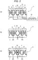
Figs. 2(a) to 2(c) are cross-sectional views illustrating operation of the liquid droplet ejection head. -
Fig. 3 is a diagram illustrating a drive waveform for achieving a method for driving a liquid droplet ejection head of a first embodiment. -
Fig. 4 is a diagram illustrating a change in ejection pressure according to the method for driving a liquid droplet ejection head of the first embodiment. -
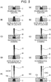
Figs. 5(A) to 5(E) are diagrams illustrating a meniscus and a state of liquid droplet ejection in a nozzle by the method for driving a liquid droplet ejection head of the first embodiment, andFigs. 5(a) to 5(e) are diagrams illustrating a meniscus and a state of liquid droplet ejection in a nozzle by a method for driving a conventional liquid droplet ejection head. -
Fig. 6 is a graph illustrating a reverberation extrusion pressure generated by the drive waveform illustrated inFig. 3 . -
Fig. 7 is a diagram illustrating a drive waveform for achieving a method for driving a liquid droplet ejection head of a second embodiment. -
Fig. 8 is a diagram illustrating a drive waveform for achieving a method for driving a liquid droplet ejection head of a third embodiment. -
Fig. 9 is a graph showing a relationship between a liquid droplet velocity and a satellite length as an example of the present invention. -
Figs. 10(a) and 10(b) are explanatory views illustrating a state of liquid droplet ejection by a conventional driving method. -
Fig. 11 is a diagram illustrating a drive waveform in a conventional driving method. - Embodiments of the present invention will be described below with reference to the drawings.
- [First Embodiment]
-
Fig. 1 is a perspective view illustrating an aspect of a liquid droplet ejection head to which the present invention is applied. -
Figs. 2(a) to 2(c) are cross-sectional views illustrating operation of the liquid droplet ejection head. - As illustrated in
Figs. 1 and2 , the method for driving a liquid droplet ejection head according to the present invention can be applied to any type of liquid droplet ejection head as long as the liquid droplet ejection head includes anozzle 3 for ejecting liquid droplets, a pressure generation chamber A capable of storing liquid therein and communicating with thenozzle 3, and a pressure application unit that changes an internal pressure of the pressure generation chamber A, and the liquid filled in the pressure generation chamber may be any liquid. - In the description below, a case will be described in which the present invention is applied to a shearing mode type inkjet recording head H including a piezoelectric element S serving as a pressure application unit that changes an internal force by increasing or reducing a volume in the pressure generation chamber A, the liquid droplet ejection head H using ink as liquid filled in the pressure generation chamber A, the liquid droplet ejection head H being deformed in a shearing mode (shear mode) by application of an electric field by the piezoelectric element S.
- As illustrated in
Fig. 1 , the liquid droplet ejection head H is configured such that anozzle plate 1 is attached to a front end surface of achannel substrate 2 and amanifold member 4 is attached to a rear end surface of thechannel substrate 2. Thenozzle plate 1 is provided with a plurality ofnozzles 3 for ejecting ink droplets. - As illustrated in
Figs. 1 and2 , thechannel substrate 2 is provided with a plurality of pressure generation chambers A. A plurality of pressure generation chambers A are arranged in parallel via piezoelectric elements S serving as partition walls. By alternately arranging the pressure generation chambers A and the piezoelectric elements S in parallel, one piezoelectric element S is shared by the pressure generation chambers A on both sides thereof. - One end of each pressure generation chamber A in the longitudinal direction communicates with the
nozzle 3. The liquid droplet ejection head H of the present embodiment is a liquid droplet ejection head that performs so-called "independent driving" in which an ejection channel communicating with thenozzle 3 and a dummy channel (also referred to as a non-ejection channel) in which thenozzle 3 is not provided are alternately arranged in parallel as the pressure generation chamber A. However, the present embodiment is not limited thereto, and a liquid droplet ejection head that performs so-called "three-cycle driving" in which all ink channels are divided into three groups and adjacent ink channels are controlled in a time division manner may be used. - The piezoelectric element S includes an upper wall S1 and a lower wall S2 made of piezoelectric materials with polarization directions opposite to each other. The piezoelectric material is not particularly limited, and for example, lead zirconate titanate (PZT) or the like can be used.
- A manifold 41, which is an internal space, is formed in the
manifold member 4 attached to the rear end surface of thechannel substrate 2. The other end in the longitudinal direction of each pressure generation chamber A communicates with the manifold 41. The manifold 41 communicates with an ink tank (not illustrated) by anink tube 42. - The ink supplied from the ink tank is supplied from the manifold 41 to each pressure generation chamber A. Each pressure generation chamber A forms a flow path connecting the manifold 41 and the
nozzle 3. Each pressure generation chamber A forms an individual flow path corresponding to eachnozzle 3. A meniscus made of ink is formed in thenozzle 3. - Electrodes Q1, Q2, Q3, Q4 are formed on the surface of the piezoelectric element S constituting each pressure generation chamber A. Each of the electrodes Q1, Q2, Q3, Q4 is connected to a drive
signal generation unit 50 that supplies a drive signal for driving the piezoelectric element S to eject the ink in the pressure generation chamber A. - In
Fig. 2 , arrows attached to the piezoelectric element S indicate polarization directions of the upper wall S1 and the lower wall S2. As described above, the upper wall S1 and the lower wall S2 made of the piezoelectric material can be arranged so that polarization directions thereof are opposite to each other. The piezoelectric element S is driven to change the volume in the pressure generation chamber A by applying a voltage, and is configured to apply different pressures to the pressure generation chamber A by applying different voltages. - When no drive signal is applied to any of the electrodes Q1, Q2, Q3, Q4, as illustrated in
Fig. 2(a) , none of the piezoelectric elements S is deformed. In this state, when the electrodes Q1 and Q4 on the side far from the pressure generation chamber A are grounded and a drive signal (+V) is applied to the electrodes Q2, Q3 facing the inside of the pressure generation chamber A, an electric field in a direction perpendicular to the polarization direction of the piezoelectric elements S, S is generated, and as illustrated inFig. 2(b) , the piezoelectric elements S, S are deformed toward the outside of the pressure generation chamber A by causing displacement deformation on the joint surfaces of the upper wall S1 and the lower wall S2. By this deformation, the volume of the pressure generation chamber A is increased, a negative pressure is generated in the pressure generation chamber A, and the ink flows into the pressure generation chamber A from the manifold 41. - When the potentials of the electrodes Q2, Q3 are returned from this state to 0, the piezoelectric elements S, S return from an expansion position illustrated in
Fig. 2(b) to a neutral position illustrated inFig. 2(a) , and pressure is applied to the ink in the pressure generation chamber A. - In this state, when a drive signal (-V) is applied to the electrodes Q2, Q3 facing the inside of the pressure generation chamber A, an electric field in a direction perpendicular to the polarization direction of the piezoelectric elements S, S is generated, and as illustrated in
Fig. 2(c) , the piezoelectric elements S, S are deformed toward the inside of the pressure generation chamber A. By this deformation, the volume of the pressure generation chamber A is reduced, a positive pressure is generated in the pressure generation chamber A, and the ink is ejected from thenozzle 3 corresponding to the pressure generation chamber A. By such a series of operations of the piezoelectric elements S, S based on the drive signal, the ink droplets are separated from the meniscus in thenozzle 3 communicating with the pressure generation chamber A, and the ink droplets are ejected from thenozzle 3. -
Fig. 3 is a diagram illustrating a drive waveform for achieving a method for driving a liquid droplet ejection head of a first embodiment. -
Fig. 4 is a diagram illustrating a change in ejection pressure according to the method for driving a liquid droplet ejection head of the first embodiment. -
Figs. 5(A) to 5(E) are diagrams illustrating a meniscus and a state of liquid droplet ejection in a nozzle by the method for driving a liquid droplet ejection head of the first embodiment, andFigs. 5(a) to 5(e) are diagrams illustrating a meniscus and a state of liquid droplet ejection in a nozzle by a method for driving a conventional liquid droplet ejection head. - In the drive waveform in this embodiment, as illustrated in
Fig. 3 (P1), the first rising pulse is applied as a first step P1 in the initial state of the recording head H illustrated inFig. 2(a) . In the first step P1, for example, the electrodes Q1, Q4 on the side far from the pressure generation chamber A are connected to the ground, a +V potential is applied to the electrodes Q2, Q3 on the side close to the pressure generation chamber A, and the volume of the pressure generation chamber A is increased by the piezoelectric elements S, S. - At this time, an electric field in a direction perpendicular to the polarization direction of the piezoelectric elements S, S constituting the partition walls on both sides of the pressure generation chamber A is generated. Then, as illustrated in
Fig. 2(b) , the piezoelectric elements S, S are deformed outward, and the volume of the pressure generation chamber A is increased (Draw). Due to the increase in volume of the pressure generation chamber A, the ink is introduced into the pressure generation chamber A. - As illustrated in
Fig. 4 , the pressure in the pressure generation chamber A is repeatedly inverted in a 1 AL period at a step interval at which the drive waveform does not change. Therefore, when this step interval is continued by 1 AL, the drawn meniscus M returns to a tip end surface (hereinafter, the tip end surface of thenozzle 3 on the liquid droplet ejection side is referred to as a "return position" of the meniscus M) on the liquid droplet ejection side in thenozzle 3, and the pressure of the ink is inverted to a positive pressure as illustrated inFig. 5(A) . When the increased pressure generation chamber A is returned to the original neutral state (Release) at this timing, a high pressure is applied to the ink in the pressure generation chamber A. As illustrated inFig. 4 , the ink pressure in thenozzle 3 changes slightly behind the change in the drive waveform, and the change in the meniscus M further slightly delays. - As described above, note that "AL" is 1/2 of the acoustic resonance period of the pressure generation chamber. This AL is obtained as a time when the flying speed of the ink droplet is maximized when the speed of the ink droplet ejected by applying a voltage pulse of a rectangular wave to the piezoelectric element S is measured, the voltage value of the rectangular wave is made constant, and the step interval of the rectangular wave is changed. The step interval is defined as from 10% of the start of the rise or fall of the voltage to the start of the next step.
- In this embodiment, a rectangular wave is used, and the rectangular wave has a waveform in which both a rise time and a fall time between 10% and 90% of the voltage are preferably within 1/2 and more preferably within 1/4 of AL. In the present invention, a triangular wave may be used without being limited to a rectangular wave. In the case of using a triangular wave, it is sufficient that, in the waveform, the pressure fluctuation in the pressure generation chamber is similar to that in the case of using a rectangular wave.
- After the first step, as illustrated in
Figs. 2(c) and3 (P2), a falling pulse (-V) is applied as a second step P2. In the second step P2, the volume of the pressure generation chamber A is reduced by the piezoelectric elements S, S, and the liquid in the pressure generation chamber A is ejected from the nozzle. - The step interval from the first step P1 to the second step P2 is preferably 0.7 to 1.3 AL. This is because when the negative pressure wave due to the volume increase of the pressure generation chamber A applied in the first step P1 is inverted by 1 AL to become a positive pressure wave, the positive pressure wave due to the volume reduction in the second step P2 is added thereto, and the ink ejection pressure increases.
- By this second step P2, the volume of the pressure generation chamber A is reduced, and as illustrated in
Fig. 4 , a higher pressure is applied to the ink (Reinforce), and as illustrated inFig. 5(B) , theink column 10 is ejected from thenozzle 3. - In the present specification, the "ink column" refers to an ink in a state in which the tip is ejected from the
nozzle 3 but the rear end is connected to the meniscus in thenozzle 3 and is not yet separated from the meniscus, and the "liquid droplet" refers to an ink in a state in which the rear end of the ink column is completely separated from the meniscus in thenozzle 3. - After the step interval of 0.4 to 1.55 AL has elapsed from the second step P2, the piezoelectric elements S, S are returned to the neutral positions as the third step P3 as illustrated in
Figs. 2(a) and3 (P3). In the third step P3, the volume of the pressure generation chamber A is increased from the reduced state by the piezoelectric element S. - The vibration (reverberation vibration) in the pressure generation chamber A is amplified by the third step P3. Note that reverberation vibration is most amplified when the step interval from the second step P2 to the third step P3 is set to 1AL.
- When 1AL has elapsed from the second step P2, as illustrated in
Fig. 4 , the pressure of the ink is reversed to become a negative pressure, so that a constriction occurs at the base of the ejectedink column 10 as illustrated inFig. 5(C) . When another 0.5 AL elapses, the negative pressure is maximized and the meniscus M is drawn to the deepest position in the direction opposite to thenozzle 3, and the meniscus M appears clearly. - When 0.5 AL further elapses, the pressure is reversed to become a positive pressure, and the meniscus M moves toward the return position. As illustrated in
Figs. 4 and5(D) , since the reverberation is larger than the conventional drive waveform by the third step P3, the meniscus M is pushed out from thenozzle 3 together with the constricted portion by reverberation extrusion. - When the time further elapses, the meniscus M returns to the return position as illustrated in
Figs. 4 and5(E) . The meniscus M drawn deep into thenozzle 3 rapidly starts to move toward the return position due to combination of the capillary force of the ink and the positive ink pressure. When the meniscus M returns to the return position, theink column 10 is not yet separated from the meniscus M, and itstail portion 10b is connected to the meniscus M. - As the meniscus M retreats from the
nozzle 3 in the direction opposite to the liquid droplet ejection direction, theink column 10 ejected from thenozzle 3 in the second step P2 is separated from the meniscus M and ejected from thenozzle 3 as a liquid droplet. At this time, the distance from the tip of the liquid droplet to thetail portion 10b separated from the meniscus M is shorter than that of the conventional drive waveform, and thereby, satellites (landing of liquid droplets separated from a main droplet) can be preferably prevented. - As described above, in this embodiment, the third step P3 is performed after the step interval of 0.4 to 1.55 AL has elapsed from the second step P2 using the DRR waveform, and the volume of the pressure generation chamber A is increased by the third step P3 to amplify the vibration (reverberation vibration) in the pressure generation chamber A. The present inventor has confirmed that it is effective for preventing satellites to promote disconnection of liquid droplets by performing drawing (third step P3) so as to apply a pressure of a phase that amplifies vibration (reverberation vibration) in the pressure generation chamber after extrusion (second step P2) after drawing (first step P1) of the ink.
- The step interval from the second step P2 to the third step P3 is preferably 0.4 to 1.1 AL. Also in this case, reverberation vibration is amplified as compared with the conventional drive waveform, disconnection of liquid droplets is promoted, and satellites can be preferably prevented.
- The step interval from the second step P2 to the third step P3 is preferably 0.4 to 0.9 AL. Also in this case, reverberation vibration is amplified as compared with the conventional drive waveform, disconnection of liquid droplets is promoted, and satellites can be preferably prevented.
- In the above description, it is preferable that a volume U1 of the pressure generation chamber A when increased in the first step P1 is larger than the volume before the pressure generation chamber A is increased in the first step P1, a volume U2 of the pressure generation chamber A when reduced in the second step P2 is smaller than the volume before the pressure generation chamber A is increased in the first step, and a volume U3 of the pressure generation chamber A when increased in the third step is substantially the same as the volume before the pressure generation chamber A is increased in the first step.
- As illustrated in
Fig. 3 , when a voltage applied to the piezoelectric element S before the first step P1 is V3(V), a voltage applied to the piezoelectric element S in the first step P1 is V1(V), a voltage applied to the piezoelectric element S in the second step P2 is V2(V), and a voltage applied to the piezoelectric element S in the third step P3 is V3(V), V2 < V3 < V1 is preferably satisfied. Thus, volume U2 < volume U3 < volume U1 is satisfied. Note that the voltage V3 in the initial state is not limited to 0, and each of the voltages VI, V2, V3 is a voltage of a difference. - As described above, according to the drive waveform of the embodiment, satellites can be preferably prevented by amplifying the reverberation vibration. Hereinafter, this effect will be described in comparison with a conventional drive waveform.
- In the conventional drive waveform, as illustrated in
Figs. 4 and5(a) to 5(c) , the pressure fluctuation and the behavior of the ink in the pressure generation chamber A from the first step P1 to the second step P2 are similar to those in the above-described embodiment illustrated inFigs. 5(A) to 5(C) . - After 1.5 AL elapses from the second step P2, as illustrated in
Figs. 4 ,5(C), and 5(c) , the negative pressure is maximized, the meniscus M is drawn to the deepest position in the direction opposite to thenozzle 3, and the meniscus M clearly appears. - When 0.5 AL further elapses (the step interval of 2 AL elapses from the second step P2), in the conventional drive waveform, as illustrated in
Figs. 4 and5(d) , the pressure is reversed to become positive pressure, and the meniscus M moves toward the return position. At this time, as the third step P3 of increasing the volume of the pressure generation chamber A, the partition wall S is returned to the neutral position, and the volume of the pressure generation chamber A is increased from the reduced state so far. By the third step P3, the vibration (reverberation vibration) in the pressure generation chamber A is canceled, and the meniscus M returns to the return position. - When the meniscus M returns to the return position, the
ink column 10 is not yet separated from the meniscus M, and itstail portion 10b is connected to the meniscus M. In the conventional drive waveform, as illustrated inFig. 5(e) , theink column 10 ejected from thenozzle 3 is separated from the meniscus M and ejected from thenozzle 3 as a liquid droplet. - At this time, the distance from the tip of the liquid droplet to the
tail portion 10b separated from the meniscus M is longer than the drive waveform of the above-described embodiment illustrated inFig. 5(E) , and satellites are not sufficiently prevented. In the drive waveform of the embodiment, since the disconnection of the liquid droplet is promoted, the distance from the tip portion of the liquid droplet to thetail portion 10b is short, and satellites are preferably prevented. -
Fig. 6 is a graph illustrating a reverberation extrusion pressure generated by the drive waveform illustrated inFig. 3 . - In the drive waveform of the above-described embodiment, as illustrated in
Fig. 6 , between the step interval (horizontal axis) from the second step P2 to the third step P3 and the extrusion pressure (vertical axis) due to reverberation with respect to the meniscus M after the third step P3, there is a relationship that the extrusion pressure becomes positive pressure when the step interval is 0.4 to 1.55 AL, and the extrusion pressure becomes maximum when the step interval is 1 AL. - Even when the step interval from the second step P2 to the third step P3 is set to 0.4 to 1.1 AL or 0.4 to 0.9 AL, the reverberation vibration is sufficiently amplified to promote the disconnection of the liquid droplets and preferably prevent satellites.
-
Fig. 7 is a diagram illustrating a drive waveform for achieving a method for driving a liquid droplet ejection head of a second embodiment. - As illustrated in
Fig. 7 , the drive waveform of this embodiment is obtained by adding a canceling waveform for canceling reverberation vibration after the third step P3. The canceling waveform includes a fourth step P4 of reducing the volume of the pressure generation chamber A by the piezoelectric element S after 2.75 to 3.25 AL elapses from the second step P2, and a fifth step P5 of increasing the volume of the pressure generation chamber A by the piezoelectric element S and returning the volume after 0.75 to 1.25 AL elapses from the fourth step P4. - The voltage applied to the piezoelectric element S in the fourth step P4 is preferably equal to the voltage V2 applied in the second step P2. The voltage applied to the piezoelectric element S in the fifth step P5 is preferably equal to the voltage V3 (initial potential) applied in the third step P3.
- With this canceling waveform, vibration (reverberation vibration) in the pressure generation chamber A is canceled, and the next liquid droplet ejection can be preferably performed.
- In a case where the same pixel is formed by performing liquid droplet ejection following the previous liquid droplet ejection, it is preferable to perform a pre-step Pp of reducing the volume of the pressure generation chamber A by the piezoelectric element S before the first step P1. The step interval from the pre-step Pp to the first step P1 is, for example, 0.3 AL. The voltage applied to the piezoelectric element S in the pre-step Pp is preferably equal to the voltage V2 applied in the second step P2.
- By adding the pre-step Pp, the flying speed of the liquid droplet ejected in the second step P2 can be increased, and the landing position deviation from the previous ejected liquid droplet can be prevented.
-
Fig. 8 is a diagram illustrating a drive waveform for achieving a method for driving a liquid droplet ejection head of a third embodiment. - As illustrated in
Fig. 8 , the drive waveform of this embodiment is a drive waveform in a case where a plurality of droplets are continuously ejected. The last ejection of the plurality of droplets is performed using the drive waveform of the above-described embodiment. - The ejection of the first droplet is a waveform in which two liquid droplets are continuously ejected, and the liquid droplets are coalesced in the air and then landed. The ejection of the second droplet and the third droplet is a conventional DRR waveform. The ejection of the fourth droplet is the drive waveform of the first and second embodiments described above. The numerical values in
Fig. 8 indicate the step interval as a coefficient of AL. - As described above, by performing the last ejection when the ejection of the plurality of droplets is continuously performed using the drive waveform of the above-described embodiments, it is possible to preferably prevent satellites that occur in the last ejection, which is particularly problematic.
- In each of the embodiments described above, the liquid to be ejected is ink, but the liquid is not limited to the ink, and the capillary permeation rate of the liquid is expressed as {2 · (capillary radius) · (surface tension) · cos (contact angle)}/{8 · (viscosity) · (pipe length)}. The capillary permeation rate is greatly affected by the viscosity and surface tension of the liquid. For example, when comparing a liquid having a surface tension of 40 dyne/cm and a viscosity of 2 cp with a liquid having a surface tension of 28 dyne/cm and a viscosity of 10 cp, the capillary permeation rate of the latter liquid decreases to 1/10 of that of the former liquid at the same capillary radius and the same tube length.
- Therefore, the timing of returning the meniscus M to the return position differs due to the difference in liquid viscosity, the return of the meniscus M is delayed in a liquid having a high viscosity, and conversely, the return of the meniscus M is accelerated in a liquid having a low viscosity. Similarly, the timing of returning the meniscus M to the return position differs due to the difference in surface tension of the liquid, the return of the meniscus M is delayed in a liquid having a low surface tension, and conversely, the return of the meniscus M is accelerated in a liquid having a high surface tension.
- When the timing of returning the meniscus M to the return position is different due to the difference in liquid viscosity and surface tension as described above, it is assumed that the third step P3 is performed when 0.4 to 1.55 AL elapses from the second step P2, and then the meniscus M substantially returns to the return position earlier or later. If the return of the meniscus M to the return position is earlier or later, there is a possibility that the meniscus M cannot be pushed out well by reverberant vibration.
- Therefore, the driving method of the present invention exhibits a remarkable effect when the viscosity of the ejected liquid is 5 cp or more and 15 cp or less and the surface tension of the liquid is 20 dyne/cm or more and 30 dyne/cm or less.
- In each of the above embodiments, the pressure application unit includes the piezoelectric element S. The driving method of the present invention is preferable in that the timing of lowering the pressure in the pressure generation chamber can be easily controlled in a case where the pressure application unit includes the piezoelectric element S as described above.
- In each embodiment, a drive waveform of a rectangular wave is applied to the piezoelectric element. The use of the rectangular wave is preferable because the start timing of the third step P3 can be easily set at the timing when the meniscus M returns to the return position, a strong negative pressure is generated in the third step P3, and the liquid droplets can be easily separated.
- In the above-described embodiment, the piezoelectric element S of a shear mode type that deforms in a shear mode by applying an electric field is used as the pressure application unit. In the shear mode type piezoelectric element, the drive waveform of the rectangular wave illustrated in
Fig. 3 can be more effectively used, the drive voltage is lowered, and more efficient driving can be performed, which is preferable. However, the present invention is not limited thereto, and for example, a piezoelectric element of another form such as a single-plate type piezoelectric actuator or a vertical vibration type laminated piezoelectric element may be used as the piezoelectric element. Other pressure application unit such as an electromechanical transducer using electrostatic force or magnetic force, or an electrothermal transducer for applying pressure using a boiling phenomenon may be used. - In the above description, the inkjet recording head for performing image recording is used as the liquid droplet ejection head, but the present invention is not limited thereto, and can be similarly applied as long as it includes a nozzle for ejecting liquid droplets, a pressure generation chamber communicating with the nozzle, and a pressure application unit for changing the pressure in the pressure generation chamber.
-
Fig. 9 is a graph showing a relationship between a liquid droplet velocity and a satellite length as an example of the present invention. - A shear mode recording head with a nozzle pitch of 180 dpi and an emission liquid droplet amount of 14 p1 was used, the step interval from the first step P1 to the second step P2 was set to 1 AL in a DRR waveform, and as illustrated in
Fig. 9 , the step interval from the second step P2 to the third step P3 was set to (1) 0.5 AL, (2) 2 AL, and (3) 4 AL, so that liquid droplets were ejected. The relationship between the liquid droplet velocity (m/s) (horizontal axis) and the satellite length (mm) (vertical axis) at that time was checked. - As illustrated in
Fig. 9 , in (1) (Example in which the step interval from the second step P2 to the third step P3 was set to 0.5 AL), satellite generation was not observed until the liquid droplet velocity reached 6.0 m/s. (2) (Comparative Example in which the step interval from the second step P2 to the third step P3 was set to 2 AL), satellite generation was observed when the liquid droplet velocity exceeded 5.0 m/s. (3) (Comparative Example in which the step interval from the second step P2 to the third step P3 was set to 4 AL), satellite generation was not observed until the liquid droplet velocity reached 6.0 m/s, but the length of satellite generated at the liquid droplet velocity exceeding 6.0 m/s was longer than (1). In (1), when the liquid droplet velocity exceeded 6.0 m/s, a satellite is generated, but the length thereof is suppressed to be shorter than (3). -
- 1
- Nozzle plate
- 2
- Channel substrate
- 3
- Nozzle
- 4
- Manifold member
- 41
- Manifold
- 42
- Ink tube
- 10
- Ink column
- 10b
- Tail portion
- 50 H
- Recording head
- A
- Pressure generation chamber
- S
- Piezoelectric element (partition wall)
- Q1
- Electrode
- Q2
- Electrode
- Q3
- Electrode
- Q4
- Electrode
- M
- Meniscus
- P1
- First step
- P2
- Second step
- P3
- Third step
Claims (14)
- A method for driving a liquid droplet ejection head including a nozzle for ejecting a liquid droplet, a pressure generation chamber capable of storing liquid therein and communicating with the nozzle, and a pressure application unit that changes an internal pressure by increasing or reducing a volume in the pressure generation chamber,
the method comprising:a first step of increasing the volume of the pressure generation chamber by the pressure application unit;a second step of reducing the volume of the pressure generation chamber by the pressure application unit and ejecting liquid in the pressure generation chamber from the nozzle after the first step; anda third step of increasing the volume of the pressure generation chamber by the pressure application unit after a lapse of 0.4 to 1.55 AL (AL is 1/2 of an acoustic resonance period of the pressure generation chamber) from the second step. - The method for driving a liquid droplet ejection head according to claim 1, wherein a step interval from the second step to the third step is 0.4 to 1.1 AL.
- The method for driving a liquid droplet ejection head according to claim 1, wherein a step interval from the second step to the third step is 0.4 to 0.9 AL.
- The method for driving a liquid droplet ejection head according to claim 1, 2, or 3, wherein a step interval from the first step to the second step is 0.7 to 1.3 AL.
- The method for driving a liquid droplet ejection head according to any one of claims 1 to 4, further comprising:a fourth step of reducing the volume of the pressure generation chamber by the pressure application unit after a lapse of 2.75 to 3.25 AL from the second step to cancel vibration in the pressure generation chamber; anda fifth step of increasing the volume of the pressure generation chamber by the pressure application unit to cancel the vibration in the pressure generation chamber after a lapse of 0.75 to 1.25 AL from the fourth step.
- The method for driving a liquid droplet ejection head according to any one of claims of 1 to 5, wherein the volume of the pressure generation chamber when reduced in the second step is smaller than a volume before the pressure generation chamber is increased in the first step, and the volume of the pressure generation chamber when increased in the third step is substantially the same as the volume before the pressure generation chamber is increased in the first step.
- The method for driving a liquid droplet ejection head according to any one of claims 1 to 6, wherein the pressure application unit is driven so that the volume in the pressure generation chamber is changed by applying a voltage, and is configured to apply different pressures to the pressure generation chamber by applying different voltages, and when a voltage applied to the pressure application unit in the first step is V1(V), a voltage applied to the pressure application unit in the second step is V2(V), and a voltage applied to the pressure application unit in the third step is V3(V), V2 < V3 < V1 is satisfied.
- The method for driving a liquid droplet ejection head according to any one of claims 1 to 7, wherein the pressure application unit is a piezoelectric element.
- The method for driving a liquid droplet ejection head according to claim 8, wherein the piezoelectric element is deformed in a shear mode by applying an electric field.
- A method for driving a liquid droplet ejection head, the method comprising, when ejecting a plurality of droplets continuously, performing final ejection of the droplets by the method for driving a liquid droplet ejection head according to any one of claims 1 to 9.
- The method for driving a liquid droplet ejection head according to any one of claims 1 to 10, further comprising a pre-step of reducing the volume of the pressure generation chamber by the pressure application unit before the first step.
- The method for driving a liquid droplet ejection head according to any one of claims 1 to 11, wherein a drive waveform applied to the pressure application unit for changing the volume in the pressure generation chamber is a rectangular wave.
- The method for driving a liquid droplet ejection head according to any one of claims 1 to 11, wherein a drive waveform applied to the pressure application unit for changing the volume in the pressure generation chamber is a triangular wave.
- The method for driving a liquid droplet ejection head according to any one of claims 1 to 13, wherein the liquid is ink.
Applications Claiming Priority (1)
| Application Number | Priority Date | Filing Date | Title |
|---|---|---|---|
| PCT/JP2019/006839 WO2020170437A1 (en) | 2019-02-22 | 2019-02-22 | Method for driving liquid droplet ejection head |
Publications (3)
| Publication Number | Publication Date |
|---|---|
| EP3928988A1 true EP3928988A1 (en) | 2021-12-29 |
| EP3928988A4 EP3928988A4 (en) | 2022-03-02 |
| EP3928988B1 EP3928988B1 (en) | 2023-09-20 |
Family
ID=72143823
Family Applications (1)
| Application Number | Title | Priority Date | Filing Date |
|---|---|---|---|
| EP19915807.2A Active EP3928988B1 (en) | 2019-02-22 | 2019-02-22 | Method for driving liquid droplet ejection head |
Country Status (4)
| Country | Link |
|---|---|
| EP (1) | EP3928988B1 (en) |
| JP (1) | JP7188551B2 (en) |
| CN (1) | CN113453907B (en) |
| WO (1) | WO2020170437A1 (en) |
Family Cites Families (11)
| Publication number | Priority date | Publication date | Assignee | Title |
|---|---|---|---|---|
| JPS4432426B1 (en) | 1966-09-26 | 1969-12-24 | ||
| JP2005262525A (en) | 2004-03-17 | 2005-09-29 | Seiko Epson Corp | Liquid ejection head driving method, inkjet head driving method, and inkjet printer |
| JP4779578B2 (en) | 2004-12-10 | 2011-09-28 | コニカミノルタホールディングス株式会社 | Droplet discharge apparatus and droplet discharge head driving method |
| JP2006159817A (en) * | 2004-12-10 | 2006-06-22 | Konica Minolta Holdings Inc | Liquid droplet discharging device and driving method for liquid droplet discharging head |
| JP5440412B2 (en) | 2009-06-29 | 2014-03-12 | コニカミノルタ株式会社 | Ink jet recording apparatus and recording head driving method |
| JP2012135900A (en) * | 2010-12-24 | 2012-07-19 | Sii Printek Inc | Liquid jet head, liquid jet apparatus and method of driving liquid jet head |
| JP2012148534A (en) | 2011-01-21 | 2012-08-09 | Seiko Epson Corp | Liquid ejecting apparatus |
| JP5871851B2 (en) | 2013-04-16 | 2016-03-01 | 株式会社東芝 | Ink jet head driving method and driving apparatus |
| EP3127705B1 (en) | 2014-03-31 | 2020-11-04 | Konica Minolta, Inc. | Inkjet head driving method and inkjet printing apparatus |
| US9427956B2 (en) * | 2014-09-22 | 2016-08-30 | Kabushiki Kaisha Toshiba | Drive method and drive apparatus for ink jet head |
| WO2017099021A1 (en) * | 2015-12-08 | 2017-06-15 | コニカミノルタ株式会社 | Inkjet printing apparatus, inkjet head driving method, and driving waveform-designing method |
-
2019
- 2019-02-22 EP EP19915807.2A patent/EP3928988B1/en active Active
- 2019-02-22 CN CN201980092223.6A patent/CN113453907B/en active Active
- 2019-02-22 WO PCT/JP2019/006839 patent/WO2020170437A1/en not_active Ceased
- 2019-02-22 JP JP2021501266A patent/JP7188551B2/en active Active
Also Published As
| Publication number | Publication date |
|---|---|
| WO2020170437A1 (en) | 2020-08-27 |
| EP3928988B1 (en) | 2023-09-20 |
| JPWO2020170437A1 (en) | 2021-12-16 |
| JP7188551B2 (en) | 2022-12-13 |
| CN113453907A (en) | 2021-09-28 |
| CN113453907B (en) | 2023-02-21 |
| EP3928988A4 (en) | 2022-03-02 |
Similar Documents
| Publication | Publication Date | Title |
|---|---|---|
| EP1155863B1 (en) | Ink jet recording head driving method and ink jet recording device | |
| EP3127704B1 (en) | Inkjet head driving method and inkjet printing apparatus | |
| US8231194B2 (en) | Inkjet recording apparatus | |
| JP2022058820A (en) | Inkjet heads and inkjet printers | |
| CN106457823B (en) | The driving method and ink-jet recording apparatus of ink gun | |
| JP6624205B2 (en) | INK JET RECORDING APPARATUS, INK JET HEAD DRIVING METHOD, AND DRIVE WAVEFORM DESIGN METHOD | |
| CN106335279A (en) | Inkjet head and inkjet printer | |
| CN103182842B (en) | The driving method of liquid droplet ejection apparatus and liquid droplet ejection apparatus | |
| EP3238941B1 (en) | Method for driving droplet-discharging head and droplet-discharging device | |
| JP5890812B2 (en) | Inkjet head | |
| WO2014051073A1 (en) | Method for driving inkjet head, device for driving inkjet head and inkjet recording apparatus | |
| US9186891B2 (en) | Inkjet head, driving device of inkjet head and driving method thereof | |
| EP3928988B1 (en) | Method for driving liquid droplet ejection head | |
| JP5440412B2 (en) | Ink jet recording apparatus and recording head driving method | |
| JP2015089645A (en) | Ink jet head | |
| JP4474987B2 (en) | Driving method of droplet discharge head | |
| JP4474988B2 (en) | Driving method of droplet discharge head | |
| CN113844175B (en) | Liquid nozzles and printers | |
| JP4570316B2 (en) | Ink droplet ejection device | |
| JP2013199065A (en) | Liquid ejecting apparatus and driving method of the same | |
| JP5304498B2 (en) | Inkjet recording device | |
| JP4432426B2 (en) | Driving method of droplet discharge head | |
| JP2006159817A (en) | Liquid droplet discharging device and driving method for liquid droplet discharging head | |
| JP4474986B2 (en) | Driving method of droplet discharge head | |
| JP2016087918A (en) | Driving method of inkjet head and inkjet recording device |
Legal Events
| Date | Code | Title | Description |
|---|---|---|---|
| STAA | Information on the status of an ep patent application or granted ep patent |
Free format text: STATUS: THE INTERNATIONAL PUBLICATION HAS BEEN MADE |
|
| PUAI | Public reference made under article 153(3) epc to a published international application that has entered the european phase |
Free format text: ORIGINAL CODE: 0009012 |
|
| STAA | Information on the status of an ep patent application or granted ep patent |
Free format text: STATUS: REQUEST FOR EXAMINATION WAS MADE |
|
| 17P | Request for examination filed |
Effective date: 20210828 |
|
| AK | Designated contracting states |
Kind code of ref document: A1 Designated state(s): AL AT BE BG CH CY CZ DE DK EE ES FI FR GB GR HR HU IE IS IT LI LT LU LV MC MK MT NL NO PL PT RO RS SE SI SK SM TR |
|
| A4 | Supplementary search report drawn up and despatched |
Effective date: 20220131 |
|
| RIC1 | Information provided on ipc code assigned before grant |
Ipc: B41J 2/045 20060101AFI20220125BHEP |
|
| DAV | Request for validation of the european patent (deleted) | ||
| DAX | Request for extension of the european patent (deleted) | ||
| REG | Reference to a national code |
Ref country code: DE Ref country code: DE Ref legal event code: R079 Ref document number: 602019038011 Country of ref document: DE Free format text: PREVIOUS MAIN CLASS: B41J0002015000 Ipc: B41J0002045000 |
|
| GRAP | Despatch of communication of intention to grant a patent |
Free format text: ORIGINAL CODE: EPIDOSNIGR1 |
|
| STAA | Information on the status of an ep patent application or granted ep patent |
Free format text: STATUS: GRANT OF PATENT IS INTENDED |
|
| RIC1 | Information provided on ipc code assigned before grant |
Ipc: B41J 2/045 20060101AFI20230317BHEP |
|
| INTG | Intention to grant announced |
Effective date: 20230406 |
|
| P01 | Opt-out of the competence of the unified patent court (upc) registered |
Effective date: 20230510 |
|
| GRAS | Grant fee paid |
Free format text: ORIGINAL CODE: EPIDOSNIGR3 |
|
| GRAA | (expected) grant |
Free format text: ORIGINAL CODE: 0009210 |
|
| STAA | Information on the status of an ep patent application or granted ep patent |
Free format text: STATUS: THE PATENT HAS BEEN GRANTED |
|
| AK | Designated contracting states |
Kind code of ref document: B1 Designated state(s): AL AT BE BG CH CY CZ DE DK EE ES FI FR GB GR HR HU IE IS IT LI LT LU LV MC MK MT NL NO PL PT RO RS SE SI SK SM TR |
|
| REG | Reference to a national code |
Ref country code: GB Ref legal event code: FG4D |
|
| REG | Reference to a national code |
Ref country code: CH Ref legal event code: EP |
|
| REG | Reference to a national code |
Ref country code: IE Ref legal event code: FG4D |
|
| REG | Reference to a national code |
Ref country code: DE Ref legal event code: R096 Ref document number: 602019038011 Country of ref document: DE |
|
| REG | Reference to a national code |
Ref country code: LT Ref legal event code: MG9D |
|
| PG25 | Lapsed in a contracting state [announced via postgrant information from national office to epo] |
Ref country code: GR Free format text: LAPSE BECAUSE OF FAILURE TO SUBMIT A TRANSLATION OF THE DESCRIPTION OR TO PAY THE FEE WITHIN THE PRESCRIBED TIME-LIMIT Effective date: 20231221 |
|
| REG | Reference to a national code |
Ref country code: NL Ref legal event code: MP Effective date: 20230920 |
|
| PG25 | Lapsed in a contracting state [announced via postgrant information from national office to epo] |
Ref country code: SE Free format text: LAPSE BECAUSE OF FAILURE TO SUBMIT A TRANSLATION OF THE DESCRIPTION OR TO PAY THE FEE WITHIN THE PRESCRIBED TIME-LIMIT Effective date: 20230920 Ref country code: RS Free format text: LAPSE BECAUSE OF FAILURE TO SUBMIT A TRANSLATION OF THE DESCRIPTION OR TO PAY THE FEE WITHIN THE PRESCRIBED TIME-LIMIT Effective date: 20230920 Ref country code: NO Free format text: LAPSE BECAUSE OF FAILURE TO SUBMIT A TRANSLATION OF THE DESCRIPTION OR TO PAY THE FEE WITHIN THE PRESCRIBED TIME-LIMIT Effective date: 20231220 Ref country code: LV Free format text: LAPSE BECAUSE OF FAILURE TO SUBMIT A TRANSLATION OF THE DESCRIPTION OR TO PAY THE FEE WITHIN THE PRESCRIBED TIME-LIMIT Effective date: 20230920 Ref country code: LT Free format text: LAPSE BECAUSE OF FAILURE TO SUBMIT A TRANSLATION OF THE DESCRIPTION OR TO PAY THE FEE WITHIN THE PRESCRIBED TIME-LIMIT Effective date: 20230920 Ref country code: HR Free format text: LAPSE BECAUSE OF FAILURE TO SUBMIT A TRANSLATION OF THE DESCRIPTION OR TO PAY THE FEE WITHIN THE PRESCRIBED TIME-LIMIT Effective date: 20230920 Ref country code: GR Free format text: LAPSE BECAUSE OF FAILURE TO SUBMIT A TRANSLATION OF THE DESCRIPTION OR TO PAY THE FEE WITHIN THE PRESCRIBED TIME-LIMIT Effective date: 20231221 Ref country code: FI Free format text: LAPSE BECAUSE OF FAILURE TO SUBMIT A TRANSLATION OF THE DESCRIPTION OR TO PAY THE FEE WITHIN THE PRESCRIBED TIME-LIMIT Effective date: 20230920 |
|
| REG | Reference to a national code |
Ref country code: AT Ref legal event code: MK05 Ref document number: 1613143 Country of ref document: AT Kind code of ref document: T Effective date: 20230920 |
|
| PG25 | Lapsed in a contracting state [announced via postgrant information from national office to epo] |
Ref country code: NL Free format text: LAPSE BECAUSE OF FAILURE TO SUBMIT A TRANSLATION OF THE DESCRIPTION OR TO PAY THE FEE WITHIN THE PRESCRIBED TIME-LIMIT Effective date: 20230920 |
|
| PG25 | Lapsed in a contracting state [announced via postgrant information from national office to epo] |
Ref country code: IS Free format text: LAPSE BECAUSE OF FAILURE TO SUBMIT A TRANSLATION OF THE DESCRIPTION OR TO PAY THE FEE WITHIN THE PRESCRIBED TIME-LIMIT Effective date: 20240120 |
|
| PG25 | Lapsed in a contracting state [announced via postgrant information from national office to epo] |
Ref country code: AT Free format text: LAPSE BECAUSE OF FAILURE TO SUBMIT A TRANSLATION OF THE DESCRIPTION OR TO PAY THE FEE WITHIN THE PRESCRIBED TIME-LIMIT Effective date: 20230920 |
|
| PG25 | Lapsed in a contracting state [announced via postgrant information from national office to epo] |
Ref country code: ES Free format text: LAPSE BECAUSE OF FAILURE TO SUBMIT A TRANSLATION OF THE DESCRIPTION OR TO PAY THE FEE WITHIN THE PRESCRIBED TIME-LIMIT Effective date: 20230920 |
|
| PG25 | Lapsed in a contracting state [announced via postgrant information from national office to epo] |
Ref country code: SM Free format text: LAPSE BECAUSE OF FAILURE TO SUBMIT A TRANSLATION OF THE DESCRIPTION OR TO PAY THE FEE WITHIN THE PRESCRIBED TIME-LIMIT Effective date: 20230920 Ref country code: RO Free format text: LAPSE BECAUSE OF FAILURE TO SUBMIT A TRANSLATION OF THE DESCRIPTION OR TO PAY THE FEE WITHIN THE PRESCRIBED TIME-LIMIT Effective date: 20230920 Ref country code: IS Free format text: LAPSE BECAUSE OF FAILURE TO SUBMIT A TRANSLATION OF THE DESCRIPTION OR TO PAY THE FEE WITHIN THE PRESCRIBED TIME-LIMIT Effective date: 20240120 Ref country code: ES Free format text: LAPSE BECAUSE OF FAILURE TO SUBMIT A TRANSLATION OF THE DESCRIPTION OR TO PAY THE FEE WITHIN THE PRESCRIBED TIME-LIMIT Effective date: 20230920 Ref country code: EE Free format text: LAPSE BECAUSE OF FAILURE TO SUBMIT A TRANSLATION OF THE DESCRIPTION OR TO PAY THE FEE WITHIN THE PRESCRIBED TIME-LIMIT Effective date: 20230920 Ref country code: CZ Free format text: LAPSE BECAUSE OF FAILURE TO SUBMIT A TRANSLATION OF THE DESCRIPTION OR TO PAY THE FEE WITHIN THE PRESCRIBED TIME-LIMIT Effective date: 20230920 Ref country code: AT Free format text: LAPSE BECAUSE OF FAILURE TO SUBMIT A TRANSLATION OF THE DESCRIPTION OR TO PAY THE FEE WITHIN THE PRESCRIBED TIME-LIMIT Effective date: 20230920 Ref country code: PT Free format text: LAPSE BECAUSE OF FAILURE TO SUBMIT A TRANSLATION OF THE DESCRIPTION OR TO PAY THE FEE WITHIN THE PRESCRIBED TIME-LIMIT Effective date: 20240122 Ref country code: SK Free format text: LAPSE BECAUSE OF FAILURE TO SUBMIT A TRANSLATION OF THE DESCRIPTION OR TO PAY THE FEE WITHIN THE PRESCRIBED TIME-LIMIT Effective date: 20230920 |
|
| PG25 | Lapsed in a contracting state [announced via postgrant information from national office to epo] |
Ref country code: PL Free format text: LAPSE BECAUSE OF FAILURE TO SUBMIT A TRANSLATION OF THE DESCRIPTION OR TO PAY THE FEE WITHIN THE PRESCRIBED TIME-LIMIT Effective date: 20230920 Ref country code: IT Free format text: LAPSE BECAUSE OF FAILURE TO SUBMIT A TRANSLATION OF THE DESCRIPTION OR TO PAY THE FEE WITHIN THE PRESCRIBED TIME-LIMIT Effective date: 20230920 |
|
| REG | Reference to a national code |
Ref country code: DE Ref legal event code: R097 Ref document number: 602019038011 Country of ref document: DE |
|
| PG25 | Lapsed in a contracting state [announced via postgrant information from national office to epo] |
Ref country code: DK Free format text: LAPSE BECAUSE OF FAILURE TO SUBMIT A TRANSLATION OF THE DESCRIPTION OR TO PAY THE FEE WITHIN THE PRESCRIBED TIME-LIMIT Effective date: 20230920 |
|
| PLBE | No opposition filed within time limit |
Free format text: ORIGINAL CODE: 0009261 |
|
| STAA | Information on the status of an ep patent application or granted ep patent |
Free format text: STATUS: NO OPPOSITION FILED WITHIN TIME LIMIT |
|
| PG25 | Lapsed in a contracting state [announced via postgrant information from national office to epo] |
Ref country code: DK Free format text: LAPSE BECAUSE OF FAILURE TO SUBMIT A TRANSLATION OF THE DESCRIPTION OR TO PAY THE FEE WITHIN THE PRESCRIBED TIME-LIMIT Effective date: 20230920 |
|
| 26N | No opposition filed |
Effective date: 20240621 |
|
| PG25 | Lapsed in a contracting state [announced via postgrant information from national office to epo] |
Ref country code: MC Free format text: LAPSE BECAUSE OF FAILURE TO SUBMIT A TRANSLATION OF THE DESCRIPTION OR TO PAY THE FEE WITHIN THE PRESCRIBED TIME-LIMIT Effective date: 20230920 |
|
| REG | Reference to a national code |
Ref country code: CH Ref legal event code: PL |
|
| PG25 | Lapsed in a contracting state [announced via postgrant information from national office to epo] |
Ref country code: LU Free format text: LAPSE BECAUSE OF NON-PAYMENT OF DUE FEES Effective date: 20240222 |
|
| PG25 | Lapsed in a contracting state [announced via postgrant information from national office to epo] |
Ref country code: CH Free format text: LAPSE BECAUSE OF NON-PAYMENT OF DUE FEES Effective date: 20240229 |
|
| PG25 | Lapsed in a contracting state [announced via postgrant information from national office to epo] |
Ref country code: SI Free format text: LAPSE BECAUSE OF FAILURE TO SUBMIT A TRANSLATION OF THE DESCRIPTION OR TO PAY THE FEE WITHIN THE PRESCRIBED TIME-LIMIT Effective date: 20230920 |
|
| PG25 | Lapsed in a contracting state [announced via postgrant information from national office to epo] |
Ref country code: SI Free format text: LAPSE BECAUSE OF FAILURE TO SUBMIT A TRANSLATION OF THE DESCRIPTION OR TO PAY THE FEE WITHIN THE PRESCRIBED TIME-LIMIT Effective date: 20230920 Ref country code: LU Free format text: LAPSE BECAUSE OF NON-PAYMENT OF DUE FEES Effective date: 20240222 Ref country code: CH Free format text: LAPSE BECAUSE OF NON-PAYMENT OF DUE FEES Effective date: 20240229 |
|
| PG25 | Lapsed in a contracting state [announced via postgrant information from national office to epo] |
Ref country code: BG Free format text: LAPSE BECAUSE OF FAILURE TO SUBMIT A TRANSLATION OF THE DESCRIPTION OR TO PAY THE FEE WITHIN THE PRESCRIBED TIME-LIMIT Effective date: 20230920 |
|
| PG25 | Lapsed in a contracting state [announced via postgrant information from national office to epo] |
Ref country code: BG Free format text: LAPSE BECAUSE OF FAILURE TO SUBMIT A TRANSLATION OF THE DESCRIPTION OR TO PAY THE FEE WITHIN THE PRESCRIBED TIME-LIMIT Effective date: 20230920 |
|
| REG | Reference to a national code |
Ref country code: BE Ref legal event code: MM Effective date: 20240229 |
|
| PG25 | Lapsed in a contracting state [announced via postgrant information from national office to epo] |
Ref country code: BE Free format text: LAPSE BECAUSE OF NON-PAYMENT OF DUE FEES Effective date: 20240229 |
|
| PG25 | Lapsed in a contracting state [announced via postgrant information from national office to epo] |
Ref country code: IE Free format text: LAPSE BECAUSE OF NON-PAYMENT OF DUE FEES Effective date: 20240222 |
|
| PG25 | Lapsed in a contracting state [announced via postgrant information from national office to epo] |
Ref country code: IE Free format text: LAPSE BECAUSE OF NON-PAYMENT OF DUE FEES Effective date: 20240222 Ref country code: BE Free format text: LAPSE BECAUSE OF NON-PAYMENT OF DUE FEES Effective date: 20240229 |
|
| PG25 | Lapsed in a contracting state [announced via postgrant information from national office to epo] |
Ref country code: CY Free format text: LAPSE BECAUSE OF FAILURE TO SUBMIT A TRANSLATION OF THE DESCRIPTION OR TO PAY THE FEE WITHIN THE PRESCRIBED TIME-LIMIT; INVALID AB INITIO Effective date: 20190222 |
|
| PG25 | Lapsed in a contracting state [announced via postgrant information from national office to epo] |
Ref country code: HU Free format text: LAPSE BECAUSE OF FAILURE TO SUBMIT A TRANSLATION OF THE DESCRIPTION OR TO PAY THE FEE WITHIN THE PRESCRIBED TIME-LIMIT; INVALID AB INITIO Effective date: 20190222 |
|
| PG25 | Lapsed in a contracting state [announced via postgrant information from national office to epo] |
Ref country code: TR Free format text: LAPSE BECAUSE OF FAILURE TO SUBMIT A TRANSLATION OF THE DESCRIPTION OR TO PAY THE FEE WITHIN THE PRESCRIBED TIME-LIMIT Effective date: 20230920 |
|
| PGFP | Annual fee paid to national office [announced via postgrant information from national office to epo] |
Ref country code: FR Payment date: 20251231 Year of fee payment: 8 |
|
| PGFP | Annual fee paid to national office [announced via postgrant information from national office to epo] |
Ref country code: GB Payment date: 20260106 Year of fee payment: 8 |
|
| PGFP | Annual fee paid to national office [announced via postgrant information from national office to epo] |
Ref country code: DE Payment date: 20251230 Year of fee payment: 8 |