EP3928871A1 - Decanter centrifuge nozzle - Google Patents
Decanter centrifuge nozzle Download PDFInfo
- Publication number
- EP3928871A1 EP3928871A1 EP21180834.0A EP21180834A EP3928871A1 EP 3928871 A1 EP3928871 A1 EP 3928871A1 EP 21180834 A EP21180834 A EP 21180834A EP 3928871 A1 EP3928871 A1 EP 3928871A1
- Authority
- EP
- European Patent Office
- Prior art keywords
- feed chamber
- leading edge
- trailing edge
- nozzle
- centrifuge
- Prior art date
- Legal status (The legal status is an assumption and is not a legal conclusion. Google has not performed a legal analysis and makes no representation as to the accuracy of the status listed.)
- Pending
Links
Images




Classifications
-
- B—PERFORMING OPERATIONS; TRANSPORTING
- B04—CENTRIFUGAL APPARATUS OR MACHINES FOR CARRYING-OUT PHYSICAL OR CHEMICAL PROCESSES
- B04B—CENTRIFUGES
- B04B1/00—Centrifuges with rotary bowls provided with solid jackets for separating predominantly liquid mixtures with or without solid particles
- B04B1/20—Centrifuges with rotary bowls provided with solid jackets for separating predominantly liquid mixtures with or without solid particles discharging solid particles from the bowl by a conveying screw coaxial with the bowl axis and rotating relatively to the bowl
-
- B—PERFORMING OPERATIONS; TRANSPORTING
- B04—CENTRIFUGAL APPARATUS OR MACHINES FOR CARRYING-OUT PHYSICAL OR CHEMICAL PROCESSES
- B04B—CENTRIFUGES
- B04B1/00—Centrifuges with rotary bowls provided with solid jackets for separating predominantly liquid mixtures with or without solid particles
- B04B1/20—Centrifuges with rotary bowls provided with solid jackets for separating predominantly liquid mixtures with or without solid particles discharging solid particles from the bowl by a conveying screw coaxial with the bowl axis and rotating relatively to the bowl
- B04B1/2008—Centrifuges with rotary bowls provided with solid jackets for separating predominantly liquid mixtures with or without solid particles discharging solid particles from the bowl by a conveying screw coaxial with the bowl axis and rotating relatively to the bowl with an abrasion-resistant conveyor or drum
-
- B—PERFORMING OPERATIONS; TRANSPORTING
- B04—CENTRIFUGAL APPARATUS OR MACHINES FOR CARRYING-OUT PHYSICAL OR CHEMICAL PROCESSES
- B04B—CENTRIFUGES
- B04B1/00—Centrifuges with rotary bowls provided with solid jackets for separating predominantly liquid mixtures with or without solid particles
- B04B1/20—Centrifuges with rotary bowls provided with solid jackets for separating predominantly liquid mixtures with or without solid particles discharging solid particles from the bowl by a conveying screw coaxial with the bowl axis and rotating relatively to the bowl
- B04B2001/2033—Centrifuges with rotary bowls provided with solid jackets for separating predominantly liquid mixtures with or without solid particles discharging solid particles from the bowl by a conveying screw coaxial with the bowl axis and rotating relatively to the bowl with feed accelerator inside the conveying screw
Definitions
- Decanter centrifuges rely on centrifugal acceleration to continuously separate solid materials from liquids in a slurry. Decanter centrifuges can enhance the settling rate (and therefore improve separation) by keeping solids at increased centrifugal forces for longer durations.
- Settling rate in a decanter centrifuge may be a function of retention time, spinning speed, pool depth, and differential density. By accelerating the fluid more rapidly, solids may settle out faster.
- a typical decanter centrifuge includes a rotating centrifuge bowl, a conical beach at a tapered end of the bowl, a nozzle where a slurry is discharged into the bowl from an internal feed chamber, a screw conveyor to convey separated solids to a solids discharge, and a liquids discharge.
- the solids form a bowl wall cake along inside surfaces of the centrifuge bowl.
- a non-homogeneous wall cake could lead to undesirable vibration of the decanter centrifuge, thereby reducing performance and/or increasing wear on the machinery.
- An object of the present invention is to provide a reduced vibration decanter centrifuge.
- a decanter centrifuge comprising a centrifuge bowl, a feed chamber within the centrifuge bowl, the feed chamber having an axis of rotation and a direction of rotation, a scroll conveyor coaxially aligned with the feed chamber, the scroll conveyor encircling the feed chamber, comprising a plurality of conveyor flights, being rotationally locked with the feed chamber; and being in a separation zone of the centrifuge bowl, one or more nozzles providing fluid communication via a nozzle aperture from an interior volume of the feed chamber to the separation zone, each one of the one or more nozzles defining a rectangular aperture, being located such that a discharge from the one nozzle discharges into a space between two adjacent ones of the plurality of conveyor flights, having a rounded leading edge defining a first boundary of the aperture, and having a trailing edge defining a second boundary of the aperture, the leading edge and the trailing edge being delineated in that the direction of rotation of the feed chamber coincides with a direction from the trailing
- each one of the one or more nozzles comprises an inner leading edge surface and an inner trailing edge surface, the inner leading edge surface and the inner trailing edge surface extending from the leading edge and trailing edge, respectively, inside the feed chamber.
- the inner leading edge surface has a steeper incline than the inner trailing edge surface, the inclines being relative to an imaginary plane that is coplanar with tangential lines of exterior surfaces of the feed chamber.
- leading edge and the trailing edge comprise tungsten carbide.
- the nozzle aperture is framed by an aperture pad comprising a perimetric leading edge protruding inside the feed chamber.
- the trailing edge comprises an angled edge.
- the trailing edge comprises a rounded edge having a radius of curvature that is less than one-fourth of a radius of curvature of the leading edge.
- a decanter centrifuge nozzle comprising a rectangular aperture, a rounded leading edge, and a trailing edge.
- the decanter centrifuge nozzle comprises an inner leading edge surface and an inner trailing edge surface, the inner leading edge surface and the inner trailing edge surface extending from the leading edge and trailing edge, respectively, on an interior side of the nozzle.
- the inner leading edge surface has a steeper incline than the inner trailing edge surface, the inclines being relative to an imaginary plane that is coplanar with the aperture.
- leading edge and the trailing edge comprise tungsten carbide.
- the decanter centrifuge nozzle comprises an interior aperture pad perimetric leading edge.
- the trailing edge comprises an angled edge.
- the trailing edge comprises a rounded edge having a radius of curvature that is less than one-fourth of a radius of curvature of the leading edge.
- a method of separating two phases of a slurry comprising charging the slurry into a feed chamber within a centrifuge bowl of a decanter centrifuge, the feed chamber being coaxially aligned with a scroll conveyor and with the centrifuge bowl, the scroll conveyor encircling the feed chamber, comprising a plurality of conveyor flights, and being in a separation zone of the centrifuge bowl, discharging the slurry from the feed chamber into the separation zone of the centrifuge bowl via one or more nozzles, each one of the one or more nozzles comprising a rectangular aperture, being located such that discharge from the one nozzle discharges into a space between two adjacent ones of the plurality of conveyor flights, having a rounded leading edge defining a first boundary of the aperture, and having a trailing edge defining a second boundary of the aperture, the leading edge and the trailing edge being delineated in that a direction of rotation of the feed chamber coincides with a direction from the trail
- Embodiments of the present disclosure include a decanter centrifuge having one or more nozzles adapted to discharge a slurry from a centrifuge feed chamber into a separation zone within a centrifuge bowl.
- such discharge may have a shorter spiral through the separation zone compared to that of traditional discharge nozzles, which may lead to reduced disturbance of bowl wall cake.
- embodiments of the present disclosure may lead to reduced bowl wear, reduced vibration of the centrifuge, and improved solid cut point.
- tangential discharge of slurry from the nozzles into the centrifuge bowl may be associated with higher slurry exit velocity.
- one embodiment of the present disclosure comprises a decanter centrifuge 100.
- Embodiments of decanter centrifuge 100 comprise a feed chamber 110, within the interior of a centrifuge bowl 210, rotatably mounted to a base frame and housing (not shown) on one or more trunnions 150, 155.
- feed chamber 110 and centrifuge bowl 210 are adapted to rotate independently from each other within the base frame and the housing, such that feed chamber 110 and centrifuge bowl 210 may be driven at respectively different rotational speeds. In some embodiments, feed chamber 110 rotates at greater speeds than that of centrifuge bowl 210. In other embodiments, feed chamber 110 rotates at lesser speeds than that of centrifuge bowl 210.
- centrifuge bowl 210 is rotationally fixed to a base frame and/or centrifuge housing, such that it remains stationary while feed chamber 110 may rotate within the centrifuge bowl 210.
- feed chamber 110 and centrifuge bowl 210 are rotationally fixed to each other and rotate at the same time and at the same speed.
- Feed chamber 110 defines an interior volume 112 formed by outer annular walls. 114 Embodiments of feed chamber 110 comprise a cylindrical section 120 and a frustoconical section 130, the cylindrical section 120 and frustoconical section 130 being defined by respective sections of outer annular wall 114 of the feed chamber 110.
- a slurry (not shown) to be separated may be fed to feed chamber 110 via feed tube 115. The slurry may then be discharged into the separation zone 215 of centrifuge bowl 210 via nozzles 125.
- One or more nozzles 125 placed on cylindrical section 120 provide fluid communication from the interior volume 112 of feed chamber 110 to the annular volume between feed chamber 110 and centrifuge bowl 210.
- Embodiments of decanter centrifuge 100 comprise a scroll conveyor 140 coaxially aligned within centrifuge bowl 210 around the circumference of feed chamber 110.
- scroll conveyor 140 flights are fixed to the exterior walls 114 of feed chamber 110 and thus rotate in synchronization with feed chamber 110.
- scroll conveyor 140 is adapted to rotate independently from feed chamber 110.
- feed chamber 110 is supported on, and rotated by, feed trunnion 150 and gear trunnion 155.
- Feed trunnion 150 houses a portion of feed tube 115.
- gear trunnion 155 applies rotational force to rotate the feed chamber 110 relative to centrifuge bowl 210 in the direction indicated in FIG. 2 by arrow 157.
- a drive motor (not shown) is adapted to apply rotation to rotating elements of decanter centrifuge 100.
- the drive motor drives the rotation directly.
- drive motor applies rotation via a drive belt, drive gears, a drive pully, via other mechanisms, or combinations thereof.
- Embodiments of centrifuge bowl 210 comprise a cylindrical section 220 and a frustoconical section 230, which respectively encircle cylindrical section 120 and frustoconical section 130 of feed chamber 110.
- the inner inclined surfaces of the frustoconical section 230 may be known in the art as the "beach" of centrifuge bowl 210.
- centrifuge bowl 210 is adapted to rotate in a clockwise direction (looking at centrifuge bowl 210 along its axis from its end opposite frustoconical section 230).
- scroll conveyor 140 can rotate, relative to centrifuge bowl 210, in a direction indicated by arrow 157.
- Arrow 157 indicates a counterclockwise direction (looking at feed chamber 110 along its axis from its end opposite frustoconical section 130).
- this means that scroll conveyor 140 may be rotating in the same absolute direction as, but at a slower absolute rotational speed than, centrifuge bowl 210.
- this also means that scroll conveyor 140 may be rotating in an absolute direction opposite to the rotational direction of centrifuge bowl 210.
- the rotational speed of scroll conveyor 140 relative to centrifuge bowl 210 is slower than that of the second example.
- a higher rotational speed difference between scroll conveyor 140 and centrifuge bowl 210 may result in a shorter stay time for solids within centrifuge bowl 210.
- a lower rotational speed difference between scroll conveyor 140 and centrifuge bowl 210 may result in a longer stay time for solids within centrifuge bowl 210.
- embodiments of decanter centrifuge 100 comprise multiple nozzles 125 around cylindrical section 120 of feed chamber 110. As depicted in FIG. 2 , the orientation of decanter centrifuge 100 is horizontally flipped relative to its depiction in FIG. 1 . As shown by FIGS. 2 and 3 , nozzles 125 are positioned between flights of scroll conveyor 140 around exterior annular wall 114 of feed chamber 110, so that slurry may pass through nozzles 125 without impacting the flights of scroll conveyor 140.
- multiple nozzles 125 may be thus positioned, the arrangement thereof forming a helical pattern around and along the feed chamber 110 exterior wall 114.
- each nozzle 125 is positioned approximately ninety degrees apart from each other along the feed chamber 110 exterior wall 114.
- nozzles 125 are positioned closer together to each other.
- nozzles 125 are positioned farther from each other.
- nozzles 125 are also placed around frustoconical section 130 of feed chamber 110.
- nozzle 125 is seated between two adjacent flights of scroll conveyor 140. As described above, nozzles 125 are positioned between the flights to minimize impacting the flights with slurry discharge from nozzles 125. It may be desirable to maximize the size of nozzles 125, so that volumetric flow rate of slurry may be maximized while minimizing and/or reducing fluid velocity. In this manner, nozzles 125 may be sized to be as large as can fit between the flights. In other words, a limiting factor to an ideal size of nozzles 125 may be the distance between adjacent flights of scroll conveyor 140
- nozzles 125 may include any quantity of nozzles 125 as may be appropriate.
- one embodiment comprises twelve nozzles 125, roughly equally spaced around cylindrical section 120 of feed chamber 110. In other embodiments, other quantities of nozzles 125 are included.
- decanter centrifuge 100 operates to separate a concentrated heavy phase from a clarified liquid in the separation zone and separately discharge the separated phases.
- Slurry to be separated by decanter centrifuge 100 enters feed chamber 110 via feed tube 115.
- the slurry is then forced out of the feed chamber 110, through one or more nozzles 125, into the separation zone 215 (depicted in FIG. 1 ) of the centrifuge bowl 210, where the separation may occur.
- the heavy phase can be separated from the slurry by centrifugal acceleration moving solids up the frustoconical section 230 of centrifuge bowl 210 toward heavy phase discharge ports 160.
- the light phase is moved in the opposite direction, toward light phase discharge ports 165.
- Separated phases may be conveyed away from discharge ports 160, 165 and out of the decanter centrifuge as the phases are discharged therefrom. In some embodiments, more than two phases are separated from each other. Each separated phase may have one or more discharge ports where it may be discharged.
- nozzle 125 is depicted from an outside view of feed chamber 110 according to one embodiment of the present disclosure.
- Nozzle 125 comprises aperture 410.
- aperture 410 comprises a rectangular shape, which may maximize the size of the opening compared to a nozzle with a round aperture.
- a rectangular aperture 410 may provide increased flow rate through nozzle 125 for equivalent fluid velocity.
- providing lower fluid velocity may result in a lower wear rate of the nozzle 125 as well as other surrounding components, such as the flights of scroll conveyor 140 and the inside walls of centrifuge bowl 210.
- nozzles 125 of the present disclosure may exhibit improved durability of various components within decanter centrifuge 100.
- nozzle 125 comprises leading edge 420 and trailing edge 430, each defining opposing boundaries of aperture 410.
- Leading edge 420 and trailing edge 430 are delineated relative to, and in light of, rotational movement of feed chamber relative to centrifuge bowl 210 110 indicated by arrow 157.
- rotation of feed chamber 110 involves downward movement of nozzle 125, in roughly the direction from trailing edge 430 to leading edge 420.
- leading edge 420 is forward of trailing edge 430 during rotational movement of feed chamber 110.
- leading edge 420 is rounded along the length of leading edge 420 with a curvature that extends from the outer surface of nozzle 125 depicted in FIG. 4 to the inner surface of nozzle 125 (depicted in FIG. 5 ).
- trailing edge 430 comprise an edge with an acute angle.
- Other embodiments comprise a curve having a relatively small radius.
- trailing edge 430 has less curvature relative to leading edge 420.
- the radius of curvature of trailing edge 430 is less than one-third of that of leading edge 420.
- the radius of curvature of trailing edge 430 is less than one-fourth of that of leading edge 420.
- the radius of curvature of trailing edge 430 is less than one-fifth of that of leading edge 420.
- FIG. 5 interior surfaces of nozzle 125 may be seen according to an embodiment of the present disclosure. While nozzle 125 is mounted in feed chamber 110, FIG. 5 would be a view looking at nozzle 125 from within feed chamber 110 out into the annulus between feed chamber 110 and centrifuge bowl 210. As oriented in the depiction of FIG. 5 , rotation of feed chamber 110 would involve upward movement of nozzle 125, in roughly the direction from trailing edge 430 to leading edge 420.
- nozzle 125 comprises a rectangular aperture 410 framed by aperture pad 415.
- a perimetric edge of the interior-facing side of aperture pad 415 protrudes inwardly compared to adjacent interior surfaces of feed chamber 110, forming interior aperture pad perimetric leading edge 525 (also depicted in FIG. 6 ).
- perimetric refers to a boundary, or portion of a boundary, along the perimeter of an object or element.
- leading edge 525 may catch small amounts of sand, rocks, sediment, or other slurry particulate matter, thereby precipitating a small dam of such slurry matter. It is theorized that such a dam may result in lower wear rate of the nozzle 125, leading to longer service life.
- nozzles 125 may exhibit a longer service life than prior art devices because nozzles 125 comprise a larger leading area, such as leading edge 525, where potentially damaging contact with slurry particles may be distributed.
- prior art nozzles some of which are round, may tend to result in particles being concentrated on relatively small leading areas, leading to faster wear and shorter service life.
- nozzles 125 as disclosed herein may have approximately double the service life of some prior art nozzles.
- some prior art nozzles had a service life of approximately three to six months, whereas one nozzle according to embodiments of the present disclosure was tested for one year under similar conditions without failing.
- embodiments according to the present disclosure may provide the benefit of less accumulation of slurry within feed chamber 110. This benefit may be the result of increased fluid flow rates through nozzles 125 out of feed chamber 110.
- embodiments of the present disclosure include nozzles 125 assembled from multiple component parts.
- aperture pad 415 comprises tungsten carbide material (indicated by darker surface pattern), while other components of the nozzle 125 assembly comprise a stainless steel material (indicated by lighter surface pattern).
- various components of decanter centrifuge 100 including nozzles 125 and/or other components, are formed of other materials that may be suitable to applications of the decanter centrifuge. Selected materials may exhibit durability and/or low wear rate to withstand potentially damaging conditions caused by high volumes of slurry flow through decanter centrifuge 100.
- a line from leading edge 420 to trailing edge 430 of each nozzle 125 would be approximately tangential to the outer annular walls of feed chamber 110, or approximately parallel to a line that is tangential to the outer annular walls of feed chamber 110.
- tangential and tangentially refer to imaginary lines that are defined as approximately tangential to the outer annular walls of feed chamber 110 at cylindrical section 120. The tangential direction may also be perpendicular to the axis of rotation of feed chamber 110.
- lateral and laterally refer to imaginary curves that extend around the outer surfaces of the annular walls of cylindrical section 120 of feed chamber 110 and that are coplanar with tangential lines of cylindrical section 120 of feed chamber 110.
- axial and axially refer to imaginary lines that are approximately parallel to the axis of rotation of feed chamber 110.
- longitudinal and longitudinally refer to imaginary lines that extend along the length of the outer surfaces of the annular walls of cylindrical section 120 of feed chamber 110 and that are approximately parallel to axial lines.
- aperture pad 415 comprises two side members that frame aperture 410.
- the two side members are symmetrical to each other and on longitudinally opposed sides of nozzle 125.
- the side members of nozzle 125 are not symmetrical to each other.
- FIG. 6 depicts an axial section view of feed chamber 110 at cylindrical section 120 according to one embodiment.
- Leading edge 420 is adjacent to relatively steep incline on interior surface 520.
- Trailing edge 430 is adjacent to relatively shallow incline on interior surface 530.
- the respective inclines of surfaces 520, 530 are defined relative to an imaginary plane that is coplanar with aperture 410 and/or with tangential lines of cylindrical section 120 of feed chamber 110.
- the shallow incline of surface 530 may result in discharge flow from nozzle 125 that is more tangential than provided by prior art nozzles. It is understood that the relatively shallow incline of surface 530 may result in reduced shear of the slurry passing through nozzle 125 in comparison to prior art nozzles, which reduction may cause, at least in part, the slurry to flow in a more tangential direction as the slurry discharges from nozzles 125.
- FIG. 7 is a section detail showing interior surfaces of nozzle 125 within feed chamber 110 according to embodiments of the present disclosure.
- leading edge 420 and trailing edge 430 may interact with slurry passing through nozzle 125 in such a way to cause tangential, or near-tangential, flow of the slurry after it discharges through nozzle 125 into centrifuge bowl 210.
- a computational fluid dynamic (“CFD”) analysis was performed to simulate and analyze slurry discharge flow through nozzles 125 during operation of decanter centrifuge 100.
- CFD computational fluid dynamic
- a flow pattern was developed in such way that slurry discharged from nozzles 125 in a direction approximately tangential, or near tangential, to the outer annular walls of feed chamber 110.
- tangential discharge may create a shorter spiral of slurry flow inside centrifuge bowl 210.
- a shorter spiral may be less likely to disturb wall cake on the interior surfaces of centrifuge bowl 210 and hence may maintain a more homogeneous and/or evenly distributed wall cake throughout centrifuge bowl 210.
- mass balance may be maintained in the rotating assembly, which can reduce vibration and improve wear rate.
- the wall cake may act as a protective layer for interior surfaces of centrifuge bowl 210, thereby reducing wear of centrifuge bowl 210.
- a shorter spiral of slurry discharge within centrifuge bowl 210 may increase the velocity of the slurry inside centrifuge bowl 210, which can lead to better separation of solids and improved separation cut point.
Landscapes
- Centrifugal Separators (AREA)
Abstract
Description
- The present application relates to decanter centrifuges, and claims priority to and the benefit of
U.S. Pat. App. Ser. No. 16/908,341 - Decanter centrifuges rely on centrifugal acceleration to continuously separate solid materials from liquids in a slurry. Decanter centrifuges can enhance the settling rate (and therefore improve separation) by keeping solids at increased centrifugal forces for longer durations. Settling rate in a decanter centrifuge may be a function of retention time, spinning speed, pool depth, and differential density. By accelerating the fluid more rapidly, solids may settle out faster.
- A typical decanter centrifuge includes a rotating centrifuge bowl, a conical beach at a tapered end of the bowl, a nozzle where a slurry is discharged into the bowl from an internal feed chamber, a screw conveyor to convey separated solids to a solids discharge, and a liquids discharge.
- In a typical decanter centrifuge, the solids form a bowl wall cake along inside surfaces of the centrifuge bowl. As slurry is accelerated and discharged into the bowl, it can strike the wall cake, which may unevenly disturb the wall cake and result in unbalanced weight distribution within the bowl. A non-homogeneous wall cake could lead to undesirable vibration of the decanter centrifuge, thereby reducing performance and/or increasing wear on the machinery.
- An object of the present invention is to provide a reduced vibration decanter centrifuge.
- Thus, according to the present invention there is provided a decanter centrifuge comprising a centrifuge bowl, a feed chamber within the centrifuge bowl, the feed chamber having an axis of rotation and a direction of rotation, a scroll conveyor coaxially aligned with the feed chamber, the scroll conveyor encircling the feed chamber, comprising a plurality of conveyor flights, being rotationally locked with the feed chamber; and being in a separation zone of the centrifuge bowl, one or more nozzles providing fluid communication via a nozzle aperture from an interior volume of the feed chamber to the separation zone, each one of the one or more nozzles defining a rectangular aperture, being located such that a discharge from the one nozzle discharges into a space between two adjacent ones of the plurality of conveyor flights, having a rounded leading edge defining a first boundary of the aperture, and having a trailing edge defining a second boundary of the aperture, the leading edge and the trailing edge being delineated in that the direction of rotation of the feed chamber coincides with a direction from the trailing edge to the leading edge.
- Preferably, each one of the one or more nozzles comprises an inner leading edge surface and an inner trailing edge surface, the inner leading edge surface and the inner trailing edge surface extending from the leading edge and trailing edge, respectively, inside the feed chamber.
- Preferably, the inner leading edge surface has a steeper incline than the inner trailing edge surface, the inclines being relative to an imaginary plane that is coplanar with tangential lines of exterior surfaces of the feed chamber.
- Preferably, the leading edge and the trailing edge comprise tungsten carbide.
- Preferably, the nozzle aperture is framed by an aperture pad comprising a perimetric leading edge protruding inside the feed chamber.
- Preferably, the trailing edge comprises an angled edge.
- Preferably, the trailing edge comprises a rounded edge having a radius of curvature that is less than one-fourth of a radius of curvature of the leading edge.
- According to another aspect of the present invention there is provided a decanter centrifuge nozzle comprising a rectangular aperture, a rounded leading edge, and a trailing edge.
- Preferably, the decanter centrifuge nozzle comprises an inner leading edge surface and an inner trailing edge surface, the inner leading edge surface and the inner trailing edge surface extending from the leading edge and trailing edge, respectively, on an interior side of the nozzle.
- Preferably, the inner leading edge surface has a steeper incline than the inner trailing edge surface, the inclines being relative to an imaginary plane that is coplanar with the aperture.
- Preferably, the leading edge and the trailing edge comprise tungsten carbide.
- Preferably, the decanter centrifuge nozzle comprises an interior aperture pad perimetric leading edge.
- Preferably, the trailing edge comprises an angled edge.
- Preferably, the trailing edge comprises a rounded edge having a radius of curvature that is less than one-fourth of a radius of curvature of the leading edge.
- According to another aspect of the present invention there is provided a method of separating two phases of a slurry, the method comprising charging the slurry into a feed chamber within a centrifuge bowl of a decanter centrifuge, the feed chamber being coaxially aligned with a scroll conveyor and with the centrifuge bowl, the scroll conveyor encircling the feed chamber, comprising a plurality of conveyor flights, and being in a separation zone of the centrifuge bowl, discharging the slurry from the feed chamber into the separation zone of the centrifuge bowl via one or more nozzles, each one of the one or more nozzles comprising a rectangular aperture, being located such that discharge from the one nozzle discharges into a space between two adjacent ones of the plurality of conveyor flights, having a rounded leading edge defining a first boundary of the aperture, and having a trailing edge defining a second boundary of the aperture, the leading edge and the trailing edge being delineated in that a direction of rotation of the feed chamber coincides with a direction from the trailing edge to the leading edge, rotating the feed chamber in the direction of rotation, thereby imparting centrifugal acceleration upon the slurry, separating the slurry into the two phases, and discharging the two separated phases from the decanter centrifuge.
- The present disclosure is best understood, by way of example only, from the following detailed description when read with the accompanying figures.
-
FIG. 1 is a lateral, sectioned view of selected elements of a decanter centrifuge according to one or more embodiments of the disclosure. -
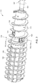
FIG. 2 depicts a feed chamber in a perspective view in the embodiment ofFIG. 1 . -
FIG. 3 is a detailed, plan view of a nozzle first shown inFIG. 2 positioned between scroll conveyor flights of the embodiment ofFIG. 1 . -
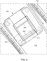
FIG. 4 is an exterior detail view of a decanter centrifuge nozzle shown inFIG. 2 andFIG. 3 according to one or more embodiments of the disclosure. -
FIG. 5 is an interior detail view of a decanter centrifuge nozzle; inFIG. 4 . -
FIG. 6 is an axial section view of a feed chamber taken along line 6-6 inFIG. 2 . -
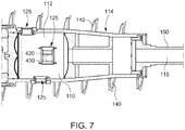
FIG. 7 is a lateral ,sectioned, detail view of a feed chamber according to one or more examples of the disclosure. - Corresponding reference characters indicate corresponding components throughout the several views of the drawings. Skilled artisans will appreciate that elements in the figures are illustrated for simplicity and clarity and have not necessarily been drawn to scale. For example, the dimensions of some of the elements in the figures may be exaggerated relative to other elements to help to improve understanding of various embodiments of the present disclosure. Also, common but well-understood elements that are useful or necessary in a commercially feasible embodiment are often not depicted in order to facilitate a less obstructed view of these various embodiments of the present disclosure.
- Embodiments of the present disclosure include a decanter centrifuge having one or more nozzles adapted to discharge a slurry from a centrifuge feed chamber into a separation zone within a centrifuge bowl. According to various embodiments, such discharge may have a shorter spiral through the separation zone compared to that of traditional discharge nozzles, which may lead to reduced disturbance of bowl wall cake. As a result, embodiments of the present disclosure may lead to reduced bowl wear, reduced vibration of the centrifuge, and improved solid cut point. According to various embodiments, tangential discharge of slurry from the nozzles into the centrifuge bowl may be associated with higher slurry exit velocity.
- Referring to
FIG. 1 , one embodiment of the present disclosure comprises adecanter centrifuge 100. Embodiments ofdecanter centrifuge 100 comprise afeed chamber 110, within the interior of acentrifuge bowl 210, rotatably mounted to a base frame and housing (not shown) on one ormore trunnions - In various embodiments,
feed chamber 110 andcentrifuge bowl 210 are adapted to rotate independently from each other within the base frame and the housing, such thatfeed chamber 110 andcentrifuge bowl 210 may be driven at respectively different rotational speeds. In some embodiments,feed chamber 110 rotates at greater speeds than that ofcentrifuge bowl 210. In other embodiments,feed chamber 110 rotates at lesser speeds than that ofcentrifuge bowl 210. - In some embodiments,
centrifuge bowl 210 is rotationally fixed to a base frame and/or centrifuge housing, such that it remains stationary whilefeed chamber 110 may rotate within thecentrifuge bowl 210. In one embodiment,feed chamber 110 andcentrifuge bowl 210 are rotationally fixed to each other and rotate at the same time and at the same speed. -
Feed chamber 110 defines aninterior volume 112 formed by outer annular walls. 114 Embodiments offeed chamber 110 comprise acylindrical section 120 and afrustoconical section 130, thecylindrical section 120 andfrustoconical section 130 being defined by respective sections of outerannular wall 114 of thefeed chamber 110. A slurry (not shown) to be separated may be fed to feedchamber 110 viafeed tube 115. The slurry may then be discharged into theseparation zone 215 ofcentrifuge bowl 210 vianozzles 125. - One or
more nozzles 125 placed oncylindrical section 120 provide fluid communication from theinterior volume 112 offeed chamber 110 to the annular volume betweenfeed chamber 110 andcentrifuge bowl 210. - Embodiments of
decanter centrifuge 100 comprise ascroll conveyor 140 coaxially aligned withincentrifuge bowl 210 around the circumference offeed chamber 110. In one embodiment, scrollconveyor 140 flights are fixed to theexterior walls 114 offeed chamber 110 and thus rotate in synchronization withfeed chamber 110. In another embodiment,scroll conveyor 140 is adapted to rotate independently fromfeed chamber 110. - According to embodiments,
feed chamber 110 is supported on, and rotated by, feedtrunnion 150 andgear trunnion 155. Feedtrunnion 150 houses a portion offeed tube 115. In the embodiment depicted,gear trunnion 155 applies rotational force to rotate thefeed chamber 110 relative tocentrifuge bowl 210 in the direction indicated inFIG. 2 byarrow 157. - In various embodiments, a drive motor (not shown) is adapted to apply rotation to rotating elements of
decanter centrifuge 100. In embodiments, the drive motor drives the rotation directly. In other embodiments, drive motor applies rotation via a drive belt, drive gears, a drive pully, via other mechanisms, or combinations thereof. - Embodiments of
centrifuge bowl 210 comprise acylindrical section 220 and afrustoconical section 230, which respectively encirclecylindrical section 120 andfrustoconical section 130 offeed chamber 110. The inner inclined surfaces of thefrustoconical section 230 may be known in the art as the "beach" ofcentrifuge bowl 210. - According to embodiments,
centrifuge bowl 210 is adapted to rotate in a clockwise direction (looking atcentrifuge bowl 210 along its axis from its end opposite frustoconical section 230). As stated above,scroll conveyor 140 can rotate, relative tocentrifuge bowl 210, in a direction indicated byarrow 157.Arrow 157 indicates a counterclockwise direction (looking atfeed chamber 110 along its axis from its end opposite frustoconical section 130). As a first example, this means thatscroll conveyor 140 may be rotating in the same absolute direction as, but at a slower absolute rotational speed than,centrifuge bowl 210. As a second example, this also means thatscroll conveyor 140 may be rotating in an absolute direction opposite to the rotational direction ofcentrifuge bowl 210. In the first example, the rotational speed ofscroll conveyor 140 relative tocentrifuge bowl 210 is slower than that of the second example. - As would be understood by a person of ordinary skill in the art having the benefit of this disclosure, a higher rotational speed difference between
scroll conveyor 140 andcentrifuge bowl 210 may result in a shorter stay time for solids withincentrifuge bowl 210. In contrast, a lower rotational speed difference betweenscroll conveyor 140 andcentrifuge bowl 210 may result in a longer stay time for solids withincentrifuge bowl 210. - Referring to
FIG. 2 , embodiments ofdecanter centrifuge 100 comprisemultiple nozzles 125 aroundcylindrical section 120 offeed chamber 110. As depicted inFIG. 2 , the orientation ofdecanter centrifuge 100 is horizontally flipped relative to its depiction inFIG. 1 . As shown byFIGS. 2 and3 ,nozzles 125 are positioned between flights ofscroll conveyor 140 around exteriorannular wall 114 offeed chamber 110, so that slurry may pass throughnozzles 125 without impacting the flights ofscroll conveyor 140. - In various embodiments of the present disclosure,
multiple nozzles 125 may be thus positioned, the arrangement thereof forming a helical pattern around and along thefeed chamber 110exterior wall 114. In one embodiment, eachnozzle 125 is positioned approximately ninety degrees apart from each other along thefeed chamber 110exterior wall 114. In other embodiments,nozzles 125 are positioned closer together to each other. In other embodiments,nozzles 125 are positioned farther from each other. In some embodiments of the present disclosure,nozzles 125 are also placed aroundfrustoconical section 130 offeed chamber 110. - As
FIG. 3 shows,nozzle 125 is seated between two adjacent flights ofscroll conveyor 140. As described above,nozzles 125 are positioned between the flights to minimize impacting the flights with slurry discharge fromnozzles 125. It may be desirable to maximize the size ofnozzles 125, so that volumetric flow rate of slurry may be maximized while minimizing and/or reducing fluid velocity. In this manner,nozzles 125 may be sized to be as large as can fit between the flights. In other words, a limiting factor to an ideal size ofnozzles 125 may be the distance between adjacent flights ofscroll conveyor 140 - Various embodiments of the present disclosure may include any quantity of
nozzles 125 as may be appropriate. For example, one embodiment comprises twelvenozzles 125, roughly equally spaced aroundcylindrical section 120 offeed chamber 110. In other embodiments, other quantities ofnozzles 125 are included. - According to various embodiments,
decanter centrifuge 100 operates to separate a concentrated heavy phase from a clarified liquid in the separation zone and separately discharge the separated phases. Slurry to be separated bydecanter centrifuge 100 entersfeed chamber 110 viafeed tube 115. The slurry is then forced out of thefeed chamber 110, through one ormore nozzles 125, into the separation zone 215 (depicted inFIG. 1 ) of thecentrifuge bowl 210, where the separation may occur. - Referring back to
FIG. 1 , the heavy phase can be separated from the slurry by centrifugal acceleration moving solids up thefrustoconical section 230 ofcentrifuge bowl 210 toward heavyphase discharge ports 160. The light phase is moved in the opposite direction, toward lightphase discharge ports 165. - As the heavy and light phases are moved toward their
respective discharge ports nozzles 125. Separated phases may be conveyed away fromdischarge ports - Referring now to
FIG. 4 ,nozzle 125 is depicted from an outside view offeed chamber 110 according to one embodiment of the present disclosure.Nozzle 125 comprisesaperture 410. In various embodiments,aperture 410 comprises a rectangular shape, which may maximize the size of the opening compared to a nozzle with a round aperture. Thus, arectangular aperture 410 may provide increased flow rate throughnozzle 125 for equivalent fluid velocity. In various embodiments, providing lower fluid velocity may result in a lower wear rate of thenozzle 125 as well as other surrounding components, such as the flights ofscroll conveyor 140 and the inside walls ofcentrifuge bowl 210. Thus,nozzles 125 of the present disclosure may exhibit improved durability of various components withindecanter centrifuge 100. - As depicted in
FIG. 4 ,nozzle 125 comprises leadingedge 420 and trailingedge 430, each defining opposing boundaries ofaperture 410. Leadingedge 420 and trailingedge 430 are delineated relative to, and in light of, rotational movement of feed chamber relative tocentrifuge bowl 210 110 indicated byarrow 157. In the depiction ofFIG. 4 , rotation offeed chamber 110 involves downward movement ofnozzle 125, in roughly the direction from trailingedge 430 to leadingedge 420. In other words, leadingedge 420 is forward of trailingedge 430 during rotational movement offeed chamber 110. - In embodiments of the present disclosure, leading
edge 420 is rounded along the length of leadingedge 420 with a curvature that extends from the outer surface ofnozzle 125 depicted inFIG. 4 to the inner surface of nozzle 125 (depicted inFIG. 5 ). - In contrast, some embodiments of trailing
edge 430 comprise an edge with an acute angle. Other embodiments comprise a curve having a relatively small radius. In various embodiments, trailingedge 430 has less curvature relative to leadingedge 420. In one embodiment, the radius of curvature of trailingedge 430 is less than one-third of that of leadingedge 420. In another embodiment, the radius of curvature of trailingedge 430 is less than one-fourth of that of leadingedge 420. In another embodiment, the radius of curvature of trailingedge 430 is less than one-fifth of that of leadingedge 420. - As shown in
FIG. 5 , interior surfaces ofnozzle 125 may be seen according to an embodiment of the present disclosure. Whilenozzle 125 is mounted infeed chamber 110,FIG. 5 would be a view looking atnozzle 125 from withinfeed chamber 110 out into the annulus betweenfeed chamber 110 andcentrifuge bowl 210. As oriented in the depiction ofFIG. 5 , rotation offeed chamber 110 would involve upward movement ofnozzle 125, in roughly the direction from trailingedge 430 to leadingedge 420. - As set forth above and as depicted in
Figs. 4-5 ,nozzle 125 comprises arectangular aperture 410 framed byaperture pad 415. According to various embodiments of the present disclosure, a perimetric edge of the interior-facing side ofaperture pad 415 protrudes inwardly compared to adjacent interior surfaces offeed chamber 110, forming interior aperture pad perimetric leading edge 525 (also depicted inFIG. 6 ). As used herein. the term "perimetric" refers to a boundary, or portion of a boundary, along the perimeter of an object or element. - As
feed chamber 110 rotates while filled with slurry, leadingedge 525 may catch small amounts of sand, rocks, sediment, or other slurry particulate matter, thereby precipitating a small dam of such slurry matter. It is theorized that such a dam may result in lower wear rate of thenozzle 125, leading to longer service life. - It is also understood that
nozzles 125 may exhibit a longer service life than prior art devices becausenozzles 125 comprise a larger leading area, such asleading edge 525, where potentially damaging contact with slurry particles may be distributed. In comparison, prior art nozzles, some of which are round, may tend to result in particles being concentrated on relatively small leading areas, leading to faster wear and shorter service life. - In putting embodiments of the present disclosure into practice, it was found that
nozzles 125 as disclosed herein may have approximately double the service life of some prior art nozzles. In particular, some prior art nozzles had a service life of approximately three to six months, whereas one nozzle according to embodiments of the present disclosure was tested for one year under similar conditions without failing. - It was found that embodiments according to the present disclosure may provide the benefit of less accumulation of slurry within
feed chamber 110. This benefit may be the result of increased fluid flow rates throughnozzles 125 out offeed chamber 110. - As shown in
FIGS. 4 and5 , embodiments of the present disclosure includenozzles 125 assembled from multiple component parts. In one embodiment,aperture pad 415 comprises tungsten carbide material (indicated by darker surface pattern), while other components of thenozzle 125 assembly comprise a stainless steel material (indicated by lighter surface pattern). In other embodiments, various components ofdecanter centrifuge 100, includingnozzles 125 and/or other components, are formed of other materials that may be suitable to applications of the decanter centrifuge. Selected materials may exhibit durability and/or low wear rate to withstand potentially damaging conditions caused by high volumes of slurry flow throughdecanter centrifuge 100. - In various embodiments of the present disclosure, a line from leading
edge 420 to trailingedge 430 of eachnozzle 125 would be approximately tangential to the outer annular walls offeed chamber 110, or approximately parallel to a line that is tangential to the outer annular walls offeed chamber 110. As used herein, the terms "tangential" and "tangentially" refer to imaginary lines that are defined as approximately tangential to the outer annular walls offeed chamber 110 atcylindrical section 120. The tangential direction may also be perpendicular to the axis of rotation offeed chamber 110. - As used herein, the terms "lateral" and "laterally" refer to imaginary curves that extend around the outer surfaces of the annular walls of
cylindrical section 120 offeed chamber 110 and that are coplanar with tangential lines ofcylindrical section 120 offeed chamber 110. As used herein, the terms "axial" and "axially" refer to imaginary lines that are approximately parallel to the axis of rotation offeed chamber 110. As used herein, the terms "longitudinal" and "longitudinally" refer to imaginary lines that extend along the length of the outer surfaces of the annular walls ofcylindrical section 120 offeed chamber 110 and that are approximately parallel to axial lines. - As further shown in
FIGS. 4 and5 ,aperture pad 415 comprises two side members thatframe aperture 410. In the embodiment depicted, the two side members are symmetrical to each other and on longitudinally opposed sides ofnozzle 125. In other embodiments, the side members ofnozzle 125 are not symmetrical to each other. -
FIG. 6 depicts an axial section view offeed chamber 110 atcylindrical section 120 according to one embodiment. Leadingedge 420 is adjacent to relatively steep incline oninterior surface 520. Trailingedge 430 is adjacent to relatively shallow incline oninterior surface 530. The respective inclines ofsurfaces aperture 410 and/or with tangential lines ofcylindrical section 120 offeed chamber 110. - The shallow incline of
surface 530, possibly in conjunction with other features ofnozzle 125, may result in discharge flow fromnozzle 125 that is more tangential than provided by prior art nozzles. It is understood that the relatively shallow incline ofsurface 530 may result in reduced shear of the slurry passing throughnozzle 125 in comparison to prior art nozzles, which reduction may cause, at least in part, the slurry to flow in a more tangential direction as the slurry discharges fromnozzles 125. -
FIG. 7 is a section detail showing interior surfaces ofnozzle 125 withinfeed chamber 110 according to embodiments of the present disclosure. As described above, leadingedge 420 and trailingedge 430 may interact with slurry passing throughnozzle 125 in such a way to cause tangential, or near-tangential, flow of the slurry after it discharges throughnozzle 125 intocentrifuge bowl 210. - A computational fluid dynamic ("CFD") analysis was performed to simulate and analyze slurry discharge flow through
nozzles 125 during operation ofdecanter centrifuge 100. In the CFD analysis, a flow pattern was developed in such way that slurry discharged fromnozzles 125 in a direction approximately tangential, or near tangential, to the outer annular walls offeed chamber 110. According to various embodiments of the present disclosure, such tangential discharge may create a shorter spiral of slurry flow insidecentrifuge bowl 210. A shorter spiral may be less likely to disturb wall cake on the interior surfaces ofcentrifuge bowl 210 and hence may maintain a more homogeneous and/or evenly distributed wall cake throughoutcentrifuge bowl 210. As a result, mass balance may be maintained in the rotating assembly, which can reduce vibration and improve wear rate. - Additionally, it is understood that the wall cake may act as a protective layer for interior surfaces of
centrifuge bowl 210, thereby reducing wear ofcentrifuge bowl 210. A shorter spiral of slurry discharge withincentrifuge bowl 210 may increase the velocity of the slurry insidecentrifuge bowl 210, which can lead to better separation of solids and improved separation cut point.
Claims (15)
- A decanter centrifuge comprising:a centrifuge bowl;a feed chamber within the centrifuge bowl, the feed chamber having an axis of rotation and a direction of rotation;a scroll conveyor coaxially aligned with the feed chamber, the scroll conveyor:encircling the feed chamber;comprising a plurality of conveyor flights;being rotationally locked with the feed chamber; andbeing in a separation zone of the centrifuge bowl;one or more nozzles providing fluid communication via a nozzle aperture from an interior volume of the feed chamber to the separation zone, each one of the one or more nozzles:
defining a rectangular aperture;being located such that a discharge from the one nozzle discharges into a space between two adjacent ones of the plurality of conveyor flights;
having a rounded leading edge defining a first boundary of the aperture; and having a trailing edge defining a second boundary of the aperture, the leading edge and the trailing edge being delineated in that the direction of rotation of the feed chamber coincides with a direction from the trailing edge to the leading edge. - The decanter centrifuge of Claim 1, each one of the one or more nozzles comprising an inner leading edge surface and an inner trailing edge surface, the inner leading edge surface and the inner trailing edge surface extending from the leading edge and trailing edge, respectively, inside the feed chamber.
- The decanter centrifuge of Claim 2, wherein the inner leading edge surface has a steeper incline than the inner trailing edge surface, the inclines being relative to an imaginary plane that is coplanar with tangential lines of exterior surfaces of the feed chamber.
- The decanter centrifuge of any preceding claim, wherein the leading edge and the trailing edge comprise tungsten carbide.
- The decanter centrifuge of any preceding claim, wherein the nozzle aperture is framed by an aperture pad comprising a perimetric leading edge protruding inside the feed chamber.
- The decanter centrifuge of any preceding claim, wherein the trailing edge comprises an angled edge.
- The decanter centrifuge of any one of claims 1 to 5, wherein the trailing edge comprises a rounded edge having a radius of curvature that is less than one-fourth of a radius of curvature of the leading edge.
- A decanter centrifuge nozzle comprising:a rectangular aperture;a rounded leading edge; anda trailing edge.
- The decanter centrifuge nozzle of Claim 8, further comprising an inner leading edge surface and an inner trailing edge surface, the inner leading edge surface and the inner trailing edge surface extending from the leading edge and trailing edge, respectively, on an interior side of the nozzle.
- The decanter centrifuge nozzle of Claim 9, wherein the inner leading edge surface has a steeper incline than the inner trailing edge surface, the inclines being relative to an imaginary plane that is coplanar with the aperture.
- The decanter centrifuge nozzle of any one of claims 8 to 10, wherein the leading edge and the trailing edge comprise tungsten carbide.
- The decanter centrifuge nozzle of any one of claims 8 to 11, comprising an interior aperture pad perimetric leading edge.
- The decanter centrifuge nozzle of any one of Claims 8 to 12, wherein the trailing edge comprises an angled edge.
- The decanter centrifuge nozzle of any one of Claims 8 to 12, wherein the trailing edge comprises a rounded edge having a radius of curvature that is less than one-fourth of a radius of curvature of the leading edge.
- A method of separating two phases of a slurry, the method comprising:charging the slurry into a feed chamber within a centrifuge bowl of a decanter centrifuge, the feed chamber being coaxially aligned with a scroll conveyor and with the centrifuge bowl, the scroll conveyor:encircling the feed chamber;comprising a plurality of conveyor flights; andbeing in a separation zone of the centrifuge bowl;discharging the slurry from the feed chamber into the separation zone of the centrifuge bowl via one or more nozzles, each one of the one or more nozzles: comprising a rectangular aperture;being located such that discharge from the one nozzle discharges into a space between two adjacent ones of the plurality of conveyor flights;having a rounded leading edge defining a first boundary of the aperture; andhaving a trailing edge defining a second boundary of the aperture, the leading edge and the trailing edge being delineated in that a direction of rotation of the feed chamber coincides with a direction from the trailing edge to the leading edge;rotating the feed chamber in the direction of rotation, thereby imparting centrifugal acceleration upon the slurry, separating the slurry into the two phases; anddischarging the two separated phases from the decanter centrifuge.
Applications Claiming Priority (1)
| Application Number | Priority Date | Filing Date | Title |
|---|---|---|---|
| US16/908,341 US11772104B2 (en) | 2020-06-22 | 2020-06-22 | Decanter centrifuge nozzle |
Publications (1)
| Publication Number | Publication Date |
|---|---|
| EP3928871A1 true EP3928871A1 (en) | 2021-12-29 |
Family
ID=76553593
Family Applications (1)
| Application Number | Title | Priority Date | Filing Date |
|---|---|---|---|
| EP21180834.0A Pending EP3928871A1 (en) | 2020-06-22 | 2021-06-22 | Decanter centrifuge nozzle |
Country Status (3)
| Country | Link |
|---|---|
| US (1) | US11772104B2 (en) |
| EP (1) | EP3928871A1 (en) |
| CA (1) | CA3122646C (en) |
Families Citing this family (1)
| Publication number | Priority date | Publication date | Assignee | Title |
|---|---|---|---|---|
| CN118577395A (en) * | 2024-05-29 | 2024-09-03 | 石家庄华莱鼎盛科技有限公司 | Drilling fluid solids control centrifuge |
Citations (6)
| Publication number | Priority date | Publication date | Assignee | Title |
|---|---|---|---|---|
| US3368747A (en) * | 1965-10-20 | 1968-02-13 | Pennsalt Chemicals Corp | Centrifuge |
| WO2003076078A1 (en) * | 2002-03-14 | 2003-09-18 | Alfa Laval Copenhagen A/S | Decanter centrifuge with wear reinforcement inlet |
| US20060240966A1 (en) * | 2005-04-25 | 2006-10-26 | Lantz Edward C | Centrifuge with shaping of feed chamber to reduce wear |
| WO2012089824A1 (en) * | 2010-12-30 | 2012-07-05 | Alfa Laval Corporate Ab | A centrifugal separator having an inlet with wear resistance members, and a feed zone element with wear resistance members |
| CN202823651U (en) * | 2012-07-31 | 2013-03-27 | 天圣环保工程(成都)有限公司 | Convenient-to-replace distribution structure of spiral pusher in horizontal spiral centrifuge |
| CN103447167A (en) * | 2013-08-12 | 2013-12-18 | 江苏捷达离心机制造有限公司 | Cloth accelerator for horizontal scroll discharge sedimentary centrifuge |
Family Cites Families (15)
| Publication number | Priority date | Publication date | Assignee | Title |
|---|---|---|---|---|
| US3228592A (en) * | 1963-11-18 | 1966-01-11 | Pennsalt Chemicals Corp | Non-spilling feed means for vertical centrifuge |
| US3398888A (en) * | 1966-08-18 | 1968-08-27 | Ethyl Corp | Centrifuge with improved discharge assembly |
| US3568919A (en) * | 1968-01-10 | 1971-03-09 | Titan Separator As | Screw centrifuge |
| US3620442A (en) * | 1969-03-17 | 1971-11-16 | Combustion Eng | Centrifuge slurry supply |
| US4323190A (en) * | 1980-05-21 | 1982-04-06 | Bird Machine Company, Inc. | Centrifuge bowl end attachment flanges |
| US5380434A (en) * | 1993-07-21 | 1995-01-10 | Tema Systems, Inc. | Centrifuge scroll with abrasion resistant inserts |
| DK143295A (en) * | 1995-12-18 | 1997-06-19 | Tetra Laval Holdings & Finance | decanter centrifuge |
| US5971907A (en) * | 1998-05-19 | 1999-10-26 | Bp Amoco Corporation | Continuous centrifugal separator with tapered internal feed distributor |
| US6780147B2 (en) * | 2000-08-31 | 2004-08-24 | Varco I/P, Inc. | Centrifuge with open conveyor having an accelerating impeller and flow enhancer |
| US6605029B1 (en) * | 2000-08-31 | 2003-08-12 | Tuboscope I/P, Inc. | Centrifuge with open conveyor and methods of use |
| US6790169B2 (en) * | 2000-08-31 | 2004-09-14 | Varco I/P, Inc. | Centrifuge with feed tube adapter |
| US7374529B2 (en) * | 2006-04-26 | 2008-05-20 | Hutchison Hayes, Lp | Liner for a centrifuge discharge port |
| US9393574B1 (en) * | 2010-12-14 | 2016-07-19 | Ray Morris | Wear insert for the solids discharge end of a horizontal decanter centrifuge |
| PL3106230T3 (en) * | 2015-06-19 | 2020-08-10 | Andritz S.A.S. | Decanter centrifuge |
| US12569862B2 (en) * | 2021-11-12 | 2026-03-10 | Sentrimax Centrifuges Inc. | Centrifuges and related methods of use to dewater mature (fluid) fine tailings |
-
2020
- 2020-06-22 US US16/908,341 patent/US11772104B2/en active Active
-
2021
- 2021-06-17 CA CA3122646A patent/CA3122646C/en active Active
- 2021-06-22 EP EP21180834.0A patent/EP3928871A1/en active Pending
Patent Citations (6)
| Publication number | Priority date | Publication date | Assignee | Title |
|---|---|---|---|---|
| US3368747A (en) * | 1965-10-20 | 1968-02-13 | Pennsalt Chemicals Corp | Centrifuge |
| WO2003076078A1 (en) * | 2002-03-14 | 2003-09-18 | Alfa Laval Copenhagen A/S | Decanter centrifuge with wear reinforcement inlet |
| US20060240966A1 (en) * | 2005-04-25 | 2006-10-26 | Lantz Edward C | Centrifuge with shaping of feed chamber to reduce wear |
| WO2012089824A1 (en) * | 2010-12-30 | 2012-07-05 | Alfa Laval Corporate Ab | A centrifugal separator having an inlet with wear resistance members, and a feed zone element with wear resistance members |
| CN202823651U (en) * | 2012-07-31 | 2013-03-27 | 天圣环保工程(成都)有限公司 | Convenient-to-replace distribution structure of spiral pusher in horizontal spiral centrifuge |
| CN103447167A (en) * | 2013-08-12 | 2013-12-18 | 江苏捷达离心机制造有限公司 | Cloth accelerator for horizontal scroll discharge sedimentary centrifuge |
Also Published As
| Publication number | Publication date |
|---|---|
| US20210394203A1 (en) | 2021-12-23 |
| CA3122646C (en) | 2025-08-05 |
| US11772104B2 (en) | 2023-10-03 |
| CA3122646A1 (en) | 2021-12-22 |
Similar Documents
| Publication | Publication Date | Title |
|---|---|---|
| US4784634A (en) | Solid bowl centrifuge | |
| EP1313565B1 (en) | Conveyor for a centrifuge, centrifuge and method of separation | |
| US4743226A (en) | High capacity continuous solid bowl centrifuge | |
| US6030332A (en) | Centrifuge system with stacked discs attached to the housing | |
| WO2003082474A2 (en) | Centrifuges and methods of separating feed material | |
| CN1305578C (en) | Spiral centrifuge | |
| EP1610900A2 (en) | Improvements in or relating to centrifuges | |
| WO2004035219A1 (en) | Centrifuge, centrifuge adapter, conveyor and method of separating material | |
| CN1003570B (en) | Parallel flow type horizontal screw centrifuge with multiple cone angles | |
| US9044762B2 (en) | Centrifugal liquid separation machine using pressurized air to promote solids transport | |
| US9321058B2 (en) | Centrifugal liquid separation machine to efficiently flow multi-phase solids from a heavy phase discharge stream with a solids plow | |
| KR890000145B1 (en) | Centrifugal separator and method of operating same | |
| US11772104B2 (en) | Decanter centrifuge nozzle | |
| US6193076B1 (en) | Drilling fluid purification method and apparatus | |
| US20210213463A1 (en) | A screen bowl decanter centrifuge | |
| JPH07241493A (en) | centrifuge |
Legal Events
| Date | Code | Title | Description |
|---|---|---|---|
| PUAI | Public reference made under article 153(3) epc to a published international application that has entered the european phase |
Free format text: ORIGINAL CODE: 0009012 |
|
| STAA | Information on the status of an ep patent application or granted ep patent |
Free format text: STATUS: THE APPLICATION HAS BEEN PUBLISHED |
|
| AK | Designated contracting states |
Kind code of ref document: A1 Designated state(s): AL AT BE BG CH CY CZ DE DK EE ES FI FR GB GR HR HU IE IS IT LI LT LU LV MC MK MT NL NO PL PT RO RS SE SI SK SM TR |
|
| B565 | Issuance of search results under rule 164(2) epc |
Effective date: 20211118 |
|
| STAA | Information on the status of an ep patent application or granted ep patent |
Free format text: STATUS: REQUEST FOR EXAMINATION WAS MADE |
|
| 17P | Request for examination filed |
Effective date: 20220627 |
|
| P01 | Opt-out of the competence of the unified patent court (upc) registered |
Effective date: 20230530 |
|
| STAA | Information on the status of an ep patent application or granted ep patent |
Free format text: STATUS: EXAMINATION IS IN PROGRESS |
|
| 17Q | First examination report despatched |
Effective date: 20250822 |