EP3928865B1 - Sample tube for polymerase chain reaction - Google Patents
Sample tube for polymerase chain reaction Download PDFInfo
- Publication number
- EP3928865B1 EP3928865B1 EP20194262.0A EP20194262A EP3928865B1 EP 3928865 B1 EP3928865 B1 EP 3928865B1 EP 20194262 A EP20194262 A EP 20194262A EP 3928865 B1 EP3928865 B1 EP 3928865B1
- Authority
- EP
- European Patent Office
- Prior art keywords
- sample tube
- extension member
- reaction mixture
- side wall
- shoulder
- Prior art date
- Legal status (The legal status is an assumption and is not a legal conclusion. Google has not performed a legal analysis and makes no representation as to the accuracy of the status listed.)
- Active
Links
Images


Classifications
-
- B—PERFORMING OPERATIONS; TRANSPORTING
- B01—PHYSICAL OR CHEMICAL PROCESSES OR APPARATUS IN GENERAL
- B01L—CHEMICAL OR PHYSICAL LABORATORY APPARATUS FOR GENERAL USE
- B01L3/00—Containers or dishes for laboratory use, e.g. laboratory glassware; Droppers
- B01L3/50—Containers for the purpose of retaining a material to be analysed, e.g. test tubes
- B01L3/508—Rigid containers without fluid transport within
- B01L3/5082—Test tubes per se
-
- B—PERFORMING OPERATIONS; TRANSPORTING
- B01—PHYSICAL OR CHEMICAL PROCESSES OR APPARATUS IN GENERAL
- B01L—CHEMICAL OR PHYSICAL LABORATORY APPARATUS FOR GENERAL USE
- B01L3/00—Containers or dishes for laboratory use, e.g. laboratory glassware; Droppers
- B01L3/50—Containers for the purpose of retaining a material to be analysed, e.g. test tubes
- B01L3/508—Rigid containers without fluid transport within
- B01L3/5082—Test tubes per se
- B01L3/50825—Closing or opening means, corks, bungs
-
- B—PERFORMING OPERATIONS; TRANSPORTING
- B01—PHYSICAL OR CHEMICAL PROCESSES OR APPARATUS IN GENERAL
- B01L—CHEMICAL OR PHYSICAL LABORATORY APPARATUS FOR GENERAL USE
- B01L3/00—Containers or dishes for laboratory use, e.g. laboratory glassware; Droppers
- B01L3/56—Labware specially adapted for transferring fluids
- B01L3/563—Joints or fittings; Separable fluid transfer means to transfer fluids between at least two containers, e.g. connectors
- B01L3/5635—Joints or fittings; Separable fluid transfer means to transfer fluids between at least two containers, e.g. connectors connecting two containers face to face, e.g. comprising a filter
-
- G—PHYSICS
- G01—MEASURING; TESTING
- G01N—INVESTIGATING OR ANALYSING MATERIALS BY DETERMINING THEIR CHEMICAL OR PHYSICAL PROPERTIES
- G01N21/00—Investigating or analysing materials by the use of optical means, i.e. using sub-millimetre waves, infrared, visible or ultraviolet light
- G01N21/01—Arrangements or apparatus for facilitating the optical investigation
- G01N21/03—Cuvette constructions
- G01N21/0303—Optical path conditioning in cuvettes, e.g. windows; adapted optical elements or systems; path modifying or adjustment
-
- B—PERFORMING OPERATIONS; TRANSPORTING
- B01—PHYSICAL OR CHEMICAL PROCESSES OR APPARATUS IN GENERAL
- B01L—CHEMICAL OR PHYSICAL LABORATORY APPARATUS FOR GENERAL USE
- B01L2300/00—Additional constructional details
- B01L2300/04—Closures and closing means
- B01L2300/041—Connecting closures to device or container
- B01L2300/042—Caps; Plugs
-
- B—PERFORMING OPERATIONS; TRANSPORTING
- B01—PHYSICAL OR CHEMICAL PROCESSES OR APPARATUS IN GENERAL
- B01L—CHEMICAL OR PHYSICAL LABORATORY APPARATUS FOR GENERAL USE
- B01L2300/00—Additional constructional details
- B01L2300/04—Closures and closing means
- B01L2300/041—Connecting closures to device or container
- B01L2300/043—Hinged closures
-
- B—PERFORMING OPERATIONS; TRANSPORTING
- B01—PHYSICAL OR CHEMICAL PROCESSES OR APPARATUS IN GENERAL
- B01L—CHEMICAL OR PHYSICAL LABORATORY APPARATUS FOR GENERAL USE
- B01L2300/00—Additional constructional details
- B01L2300/04—Closures and closing means
- B01L2300/046—Function or devices integrated in the closure
-
- B—PERFORMING OPERATIONS; TRANSPORTING
- B01—PHYSICAL OR CHEMICAL PROCESSES OR APPARATUS IN GENERAL
- B01L—CHEMICAL OR PHYSICAL LABORATORY APPARATUS FOR GENERAL USE
- B01L2300/00—Additional constructional details
- B01L2300/06—Auxiliary integrated devices, integrated components
- B01L2300/0609—Holders integrated in container to position an object
-
- B—PERFORMING OPERATIONS; TRANSPORTING
- B01—PHYSICAL OR CHEMICAL PROCESSES OR APPARATUS IN GENERAL
- B01L—CHEMICAL OR PHYSICAL LABORATORY APPARATUS FOR GENERAL USE
- B01L2300/00—Additional constructional details
- B01L2300/06—Auxiliary integrated devices, integrated components
- B01L2300/0627—Sensor or part of a sensor is integrated
- B01L2300/0654—Lenses; Optical fibres
-
- B—PERFORMING OPERATIONS; TRANSPORTING
- B01—PHYSICAL OR CHEMICAL PROCESSES OR APPARATUS IN GENERAL
- B01L—CHEMICAL OR PHYSICAL LABORATORY APPARATUS FOR GENERAL USE
- B01L2300/00—Additional constructional details
- B01L2300/08—Geometry, shape and general structure
- B01L2300/0848—Specific forms of parts of containers
- B01L2300/0851—Bottom walls
-
- B—PERFORMING OPERATIONS; TRANSPORTING
- B01—PHYSICAL OR CHEMICAL PROCESSES OR APPARATUS IN GENERAL
- B01L—CHEMICAL OR PHYSICAL LABORATORY APPARATUS FOR GENERAL USE
- B01L3/00—Containers or dishes for laboratory use, e.g. laboratory glassware; Droppers
- B01L3/50—Containers for the purpose of retaining a material to be analysed, e.g. test tubes
- B01L3/508—Rigid containers without fluid transport within
- B01L3/5085—Rigid containers without fluid transport within for multiple samples, e.g. microtitration plates
- B01L3/50851—Rigid containers without fluid transport within for multiple samples, e.g. microtitration plates specially adapted for heating or cooling samples
-
- G—PHYSICS
- G01—MEASURING; TESTING
- G01N—INVESTIGATING OR ANALYSING MATERIALS BY DETERMINING THEIR CHEMICAL OR PHYSICAL PROPERTIES
- G01N21/00—Investigating or analysing materials by the use of optical means, i.e. using sub-millimetre waves, infrared, visible or ultraviolet light
- G01N21/01—Arrangements or apparatus for facilitating the optical investigation
- G01N21/03—Cuvette constructions
- G01N2021/0378—Shapes
- G01N2021/0382—Frustoconical, tapered cell
-
- G—PHYSICS
- G01—MEASURING; TESTING
- G01N—INVESTIGATING OR ANALYSING MATERIALS BY DETERMINING THEIR CHEMICAL OR PHYSICAL PROPERTIES
- G01N21/00—Investigating or analysing materials by the use of optical means, i.e. using sub-millimetre waves, infrared, visible or ultraviolet light
- G01N21/62—Systems in which the material investigated is excited whereby it emits light or causes a change in wavelength of the incident light
- G01N21/63—Systems in which the material investigated is excited whereby it emits light or causes a change in wavelength of the incident light optically excited
- G01N21/64—Fluorescence; Phosphorescence
- G01N21/645—Specially adapted constructive features of fluorimeters
- G01N2021/6482—Sample cells, cuvettes
Definitions
- the present invention relates to a sample tube for polymerase chain reaction (PCR), and more particularly, to a sample tube for PCR capable of increasing heating area, avoiding bubble formation, adjusting reagent volumes and guiding excitation beam.
- PCR polymerase chain reaction
- PCR Polymerase chain reaction
- PCR is an important technique in molecular biology.
- PCR is carried out for 20 to 35 cycles, each of which includes following 3 steps: (1) denaturation: separating double-stranded DNA at a high temperature (94-96°C); (2) annealing: reducing temperature (68°C) so that each primer can bind to a single-strand DNA after the double-strand DNA separation; and (3) elongation: after heating to 72°C, DNA polymerase starts to synthesize a complementary strand along the DNA strand where the primer bound therefrom.
- a real-time polymerase chain reaction (RT-PCR) is directed to simultaneously perform DNA amplification and quantitative analysis in a sample analyte container after the DNA amplification is performed.
- the quantitative analysis after the DNA amplification is carried out to separate fluorescent signals of the excited analytes into multiple different optical paths, and to filter multiple signals in different frequency bands through multiple band-pass filters for analysis.
- PCR sample tubes are single sample tubes or a strip of sample tubes, and sample tube openings are sealed by sample tube covers or a strip of sample tube covers (and both sample tube covers are separated from sample tube bodies).
- Reaction mixture is added into an accommodating space of the conventional PCR sample tube, and there is air between a surface of the reaction mixture and the sample tube cover. Because the contact area between the reaction mixture and the air in the conventional PCR sample tube such as the documents US2015/231630 A1 and US2008/194014 is large, after dozens of heating and cooling cycles in the wells of the PCR reaction device, the reaction mixture is prone to disturbances at high temperature and thus bubbles are generated, thereby causing optical noises and affecting the efficiency of PCR.
- PCR polymerase chain reaction
- the present invention discloses a sample tube for a polymerase chain reaction (PCR).
- the sample tube includes a sample tube body, having an accommodating space for accommodating a reaction mixture; and a first extension member, extending from a bottom of the sample tube body to the accommodating space, wherein a light beam of a light source enters the reaction mixture via the bottom and the first extension member sequentially.
- FIG. 1 is a schematic structural diagram of a sample tube 1 according to an embodiment of the present invention.
- a sample tube 1 for polymerase chain reaction includes a sample tube body 2 and an extension member 10.
- the sample tube body 2 has an annular side wall 3 and a bottom wall 4 connected to the annular side wall 3.
- the annular side wall 3 and the bottom wall 4 form an accommodating space 5 for accommodating a reaction mixture 12.
- the extension member 10 extends from the bottom wall 4 to the accommodating space 5.
- the reaction mixture 12 immerses the extension member 10 during PCR, such that the light beam of a light source (e.g., but not limited to, excitation beam) enters the reaction mixture 12 via the bottom and the bottom wall 4 of the sample tube 1 and the extension member 10 sequentially.
- a light source e.g., but not limited to, excitation beam
- the extension member 10 extends from the bottom of the sample tube body 2 to the accommodating space 5, such that the central portion of the bottom of the sample tube 1 is raised, thereby increasing the contact area between the annular side wall 3 of the sample tube 1 and the reaction mixture 12, so as to increase the ratio of the heating area of the sample tube 1 to the volume of the reaction mixture 12.
- the contact area between the annular side wall 3 and the reaction mixture 12 is increased because of the extension member 10, and thus the heating/cooling rate during denaturation, annealing, extension steps of each PCR cycle is increased, so as to further reduce the reaction time of the PCR, thereby substantially increasing heating and heat dissipation efficiency.
- the sample tube 1 further includes a sample tube cap 6.
- the sample tube cap 6 includes a cover 7 for sealing the accommodating space 5 and an extension member 8 extending from the cover 7.
- the sample tube cap 6 is inserted into the sample tube body 2, such that the extension member 8 is arranged to face the extension member 10, and the reaction mixture 12 exists between the extension members 8 and 10.
- the extension member 10 has a top surface 11, and the extension member 8 has a top surface 9.
- the extension member 8 has a side wall 13 in contact with the top surface 9, and the side wall 13 is arranged to face the annular side wall 3. It should be noted that the extension member 8 may be made of an opaque material, or the extension member 8 is made of a transparent material and the top surface 9 has an opaque property, so that the light beam of the light source enters the reaction mixture 12 via the bottom and the bottom wall 4 of the sample tube 1 and the extension member 10 sequentially without passing through the extension member 8.
- sample tube cap 6 and sample tube body 2 are preferably arranged in parallel for ease of use (for example, it is convenient for the sample tube cap 6 having the cover 7 and the extension member 8 to be inserted into the sample tube body 2), but the side wall 13 and the annular side wall 3 can also be arranged to face each other by other methods.
- Sample tube cap 6 and sample tube body 2 may be integrally formed or may be two independent components. When being integrally formed, the sample tube cap 6 and the sample tube body 2 are connected with each other by a conventional linkage component (such as a plastic strip; not shown in FIG. 1 ), and sample tubes 1 are manufactured by procedures such as plastic injection. When being two independent components, the sample tube cap 6 is inserted into the sample tube body 2 via a conventional manner such as spiral, plug, and buckle.
- the extension member 10 extends from the bottom of the sample tube body 2 to the accommodating space 5
- the extension member 8 extends from the cover 7, there is a reaction mixture 12 residing between the extension members 8 and 10, and the side walls 13 of the extension member 8 is arranged to face the annular side wall 3 when the sample tube cap 6 is inserted into the sample tube body 2. Therefore, when the extension member 8 is inserted into the sample tube body 2, the reaction mixture 12 is distributed in an H shape in the sample tube 1 as viewed from the side of the sample tube 1, thereby reducing the contact area between the reaction mixture 12 and air within the sample tube 1.
- the cover 7 is scaled up by configuring the extension member 8 (i.e.
- a plug thereon to increase the contact area between the annular side wall 3 of the sample tube 1 and the reaction mixture 12, and to reduce the contact area between the reaction mixture 12 and air within the sample tube 1, so as to avoid bubble formation during the heating process of the PCR, disturbing optical signals and affecting the efficiency of the PCR.
- the main spirit of the present invention is to extend the bottom of the sample tube body 2 with the extension member 10 to increase the contact area between the sample tube body 2 and the reaction mixture 12, so as to improve heating and heat dissipation efficiency and reduce reaction time.
- the present invention may reduce the contact area between the reaction mixture 12 and air within the sample tube 1 by lengthening the cover 7 using the extension member 8 (i.e. a plug), to avoid bubble formation.
- the sample tube 1 may be used for any PCR device and subjected to repetitively heating and cooling, but may also be used for other reactions.
- the sample tube 1 may be placed in a heater for warming or a water bath for thermostat reaction.
- the extension member 10 illustrated in FIG. 1 increases the thickness of the center of the bottom of the sample tube 1, to maximize the contact area between the reaction mixture 12 and the annular side wall 3 of the sample tube 1.
- other areas of the bottom of the sample tube 1 may be thickened or multiple extension members are arranged on the bottom, to increase the contact area.
- shapes of the extension member 10 and the extension member 8 are individually a cylinder, a trapezoidal cylinder, a cuboid or a polyhedron.
- the shapes of the extension member 10 and the extension member 8 may be other shapes according to practical requirements, and are not limited as long as the desired functionality can be achieved.
- FIG. 2 is a schematic structural diagram of a sample tube 1' according to an embodiment of the present invention.
- the sample tube 1' and the sample tube 1 are substantially similar, and thus elements with similar functions and structures are denoted by same symbols.
- a main difference between the sample tube 1' and the sample tube 1 is that, compared to a cylindrical extension member 8 illustrated in FIG. 1 , an extension member 8' of the sample tube 1' includes a neck 8a and a shoulder 8b.
- the neck 8a is located between the cover 7 and the shoulder 8b and is connected to the cover 7 and the shoulder 8b, individually.
- the shoulder 8b is arranged to face the extension member 10.
- the length of the neck 8a and the width of the shoulder 8b of the extension member 8' (i.e. the plug) which extends from the cover 7 can be appropriately designed, so that during the sealing process of the sample tube cap 6 into the sample tube body 2, the gap d between the shoulder 8b and the annular side wall 3 gradually narrows to approach zero, and the sample tube body 2 is almost closed after sealing.
- gas i.e., for venting
- the excess reaction mixture 12 are transferred to the space 15 where almost no reaction happened and no signals would be detected.
- the present invention may adaptively control the volume of the reaction mixture 12 for the temperature cycles of the PCR, to simultaneously improve the reaction efficiency and consistency of temperature control conditions, and reduce the disturbance of reaction and optical signal caused by the exposure to air.
- the extension member 10 shown in FIG. 1 is made of a transparent material, and the bottom wall 4 functions as a converging lens; the bottom wall 4 and the extension member 10 are integrally formed, and the combination of the bottom wall 4 and the extension member 10 converge the light beam: the extension member 10 is a light guiding member/element such as a light converging lens or a light guide cylinder.
- the bottom wall 4 and the extension member converge or guide the light beam (excitation beam) of the light source, such that the light beam of the light source is more focused and optical noise can be reduced.
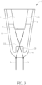
- FIG. 3 is a schematic diagram of applying excitation beam on the sample tube 1 of FIG.
- the combination of the bottom wall 4 and the extension member 10 may converges or guides the light beam L of a light source (not shown), so that the light path of the light beam L in the reaction mixture 12 of the sample tube 1 is shortened, and the light beam L is also more focused, optical signals desired for measurement are less susceptible to the disturbance of the reaction mixture 12, thereby reducing optical noise. That is, when the light beam L of the light source enters the reaction mixture 12 via the bottom and the bottom wall 4 of the sample tube 1 and the extension member 10 sequentially, the present invention can effectively reduce the optical noise in the optical path caused by the disturbance of the reaction mixture 12.
- the present invention elongates the bottom of the sample tube body 2 using the extension member 10, to increase the contact area between the annular side wall 3 and the reaction mixture 12, so as to increase the heating and heat dissipation efficiency and reduce the reaction time.
- the present invention may reduce the contact area between the reaction mixture 12 and the air, to avoid bubble formation.
- the present invention may control the volume of the reaction mixture 12 for reaction, and reduce the exposure to air.
- the bottom wall 4, the extension member 10 or the combination thereof converges or guides the light beam (excitation beam) of the light source, such that the present invention may reduce the optical noise in the optical path caused by the disturbance of the reaction mixture 12.
- sample tubes 1, 1' disclosed, but not limited to, in the embodiments of the present invention are suitable for PCR devices compatible therewith, and are also suitable for PCR and quantitative analysis after DNA amplification using such PCR devices.
Landscapes
- Health & Medical Sciences (AREA)
- Chemical & Material Sciences (AREA)
- Clinical Laboratory Science (AREA)
- Chemical Kinetics & Catalysis (AREA)
- Analytical Chemistry (AREA)
- General Health & Medical Sciences (AREA)
- Hematology (AREA)
- Life Sciences & Earth Sciences (AREA)
- Physics & Mathematics (AREA)
- Biochemistry (AREA)
- General Physics & Mathematics (AREA)
- Immunology (AREA)
- Pathology (AREA)
- Apparatus Associated With Microorganisms And Enzymes (AREA)
- Optical Measuring Cells (AREA)
- Automatic Analysis And Handling Materials Therefor (AREA)
- Devices For Use In Laboratory Experiments (AREA)
Description
- The present invention relates to a sample tube for polymerase chain reaction (PCR), and more particularly, to a sample tube for PCR capable of increasing heating area, avoiding bubble formation, adjusting reagent volumes and guiding excitation beam.
- Polymerase chain reaction (PCR), a DNA amplification, is an important technique in molecular biology. Typically, PCR is carried out for 20 to 35 cycles, each of which includes following 3 steps: (1) denaturation: separating double-stranded DNA at a high temperature (94-96°C); (2) annealing: reducing temperature (68°C) so that each primer can bind to a single-strand DNA after the double-strand DNA separation; and (3) elongation: after heating to 72°C, DNA polymerase starts to synthesize a complementary strand along the DNA strand where the primer bound therefrom. A real-time polymerase chain reaction (RT-PCR) is directed to simultaneously perform DNA amplification and quantitative analysis in a sample analyte container after the DNA amplification is performed. The quantitative analysis after the DNA amplification is carried out to separate fluorescent signals of the excited analytes into multiple different optical paths, and to filter multiple signals in different frequency bands through multiple band-pass filters for analysis.
- Conventional PCR sample tubes are single sample tubes or a strip of sample tubes, and sample tube openings are sealed by sample tube covers or a strip of sample tube covers (and both sample tube covers are separated from sample tube bodies). Reaction mixture is added into an accommodating space of the conventional PCR sample tube, and there is air between a surface of the reaction mixture and the sample tube cover. Because the contact area between the reaction mixture and the air in the conventional PCR sample tube such as the documents
US2015/231630 A1 andUS2008/194014 is large, after dozens of heating and cooling cycles in the wells of the PCR reaction device, the reaction mixture is prone to disturbances at high temperature and thus bubbles are generated, thereby causing optical noises and affecting the efficiency of PCR. - In view of this, there is a need for improvement of structure of the conventional PCR sample tube.
- It is therefore an objective of the present invention to provide a sample tube for polymerase chain reaction (PCR) capable of increasing heating area, avoiding bubble formation, adjusting reagent volumes and guiding excitation beam.
- This is achieved by a sample tube according to the
independent claim 1 here below. The dependent claims pertain to corresponding further developments and improvements. - As will be seen more clearly from the detailed description following below, the present invention discloses a sample tube for a polymerase chain reaction (PCR). The sample tube includes a sample tube body, having an accommodating space for accommodating a reaction mixture; and a first extension member, extending from a bottom of the sample tube body to the accommodating space, wherein a light beam of a light source enters the reaction mixture via the bottom and the first extension member sequentially.
-
-
FIG. 1 is a schematic structural diagram of a sample tube according to an embodiment of the present invention. -
FIG. 2 is a schematic structural diagram of a sample tube according to another embodiment of the present invention. -
FIG. 3 is a schematic diagram of applying excitation beam on the sample tube shown inFIG. 1 according to an embodiment of the present invention. - Please refer to
FIG. 1 , which is a schematic structural diagram of asample tube 1 according to an embodiment of the present invention. As shown inFIG. 1 , asample tube 1 for polymerase chain reaction (PCR) includes asample tube body 2 and anextension member 10. Thesample tube body 2 has anannular side wall 3 and abottom wall 4 connected to theannular side wall 3. Theannular side wall 3 and thebottom wall 4 form anaccommodating space 5 for accommodating areaction mixture 12. Theextension member 10 extends from thebottom wall 4 to theaccommodating space 5. Thereaction mixture 12 immerses theextension member 10 during PCR, such that the light beam of a light source (e.g., but not limited to, excitation beam) enters thereaction mixture 12 via the bottom and thebottom wall 4 of thesample tube 1 and theextension member 10 sequentially. - In this structure, because the
extension member 10 extends from the bottom of thesample tube body 2 to theaccommodating space 5, such that the central portion of the bottom of thesample tube 1 is raised, thereby increasing the contact area between theannular side wall 3 of thesample tube 1 and thereaction mixture 12, so as to increase the ratio of the heating area of thesample tube 1 to the volume of thereaction mixture 12. As a result, in the present invention, the contact area between theannular side wall 3 and thereaction mixture 12 is increased because of theextension member 10, and thus the heating/cooling rate during denaturation, annealing, extension steps of each PCR cycle is increased, so as to further reduce the reaction time of the PCR, thereby substantially increasing heating and heat dissipation efficiency. - On the other hand, the
sample tube 1 further includes asample tube cap 6. Thesample tube cap 6 includes acover 7 for sealing theaccommodating space 5 and anextension member 8 extending from thecover 7. Thesample tube cap 6 is inserted into thesample tube body 2, such that theextension member 8 is arranged to face theextension member 10, and thereaction mixture 12 exists between theextension members extension member 10 has atop surface 11, and theextension member 8 has atop surface 9. There is a distance D ranged between thetop surface 11 and thetop surface 9, so that there is thereaction mixture 12 in between and the liquid level of thereaction mixture 12 is higher than the position of thetop surface 9 in height, or the liquid level of thereaction mixture 12 is just in contact with thetop surface 9. Theextension member 8 has aside wall 13 in contact with thetop surface 9, and theside wall 13 is arranged to face theannular side wall 3. It should be noted that theextension member 8 may be made of an opaque material, or theextension member 8 is made of a transparent material and thetop surface 9 has an opaque property, so that the light beam of the light source enters thereaction mixture 12 via the bottom and thebottom wall 4 of thesample tube 1 and theextension member 10 sequentially without passing through theextension member 8. In addition, theside wall 13 and theannular side wall 3 are preferably arranged in parallel for ease of use (for example, it is convenient for thesample tube cap 6 having thecover 7 and theextension member 8 to be inserted into the sample tube body 2), but theside wall 13 and theannular side wall 3 can also be arranged to face each other by other methods.Sample tube cap 6 andsample tube body 2 may be integrally formed or may be two independent components. When being integrally formed, thesample tube cap 6 and thesample tube body 2 are connected with each other by a conventional linkage component (such as a plastic strip; not shown inFIG. 1 ), andsample tubes 1 are manufactured by procedures such as plastic injection. When being two independent components, thesample tube cap 6 is inserted into thesample tube body 2 via a conventional manner such as spiral, plug, and buckle. - In this structure, because the
extension member 10 extends from the bottom of thesample tube body 2 to theaccommodating space 5, theextension member 8 extends from thecover 7, there is areaction mixture 12 residing between theextension members side walls 13 of theextension member 8 is arranged to face theannular side wall 3 when thesample tube cap 6 is inserted into thesample tube body 2. Therefore, when theextension member 8 is inserted into thesample tube body 2, thereaction mixture 12 is distributed in an H shape in thesample tube 1 as viewed from the side of thesample tube 1, thereby reducing the contact area between thereaction mixture 12 and air within thesample tube 1. As a result, in the present invention, thecover 7 is scaled up by configuring the extension member 8 (i.e. a plug) thereon to increase the contact area between theannular side wall 3 of thesample tube 1 and thereaction mixture 12, and to reduce the contact area between thereaction mixture 12 and air within thesample tube 1, so as to avoid bubble formation during the heating process of the PCR, disturbing optical signals and affecting the efficiency of the PCR. - It is worth noting that the main spirit of the present invention is to extend the bottom of the
sample tube body 2 with theextension member 10 to increase the contact area between thesample tube body 2 and thereaction mixture 12, so as to improve heating and heat dissipation efficiency and reduce reaction time. Besides, the present invention may reduce the contact area between thereaction mixture 12 and air within thesample tube 1 by lengthening thecover 7 using the extension member 8 (i.e. a plug), to avoid bubble formation. Those skilled in the art may make modifications or alterations accordingly, which are not limited thereto. For example, thesample tube 1 may be used for any PCR device and subjected to repetitively heating and cooling, but may also be used for other reactions. For instance, thesample tube 1 may be placed in a heater for warming or a water bath for thermostat reaction. Furthermore, theextension member 10 illustrated inFIG. 1 increases the thickness of the center of the bottom of thesample tube 1, to maximize the contact area between thereaction mixture 12 and theannular side wall 3 of thesample tube 1. In other embodiments, other areas of the bottom of thesample tube 1 may be thickened or multiple extension members are arranged on the bottom, to increase the contact area. In addition, in the above embodiments, shapes of theextension member 10 and theextension member 8 are individually a cylinder, a trapezoidal cylinder, a cuboid or a polyhedron. In other embodiments, the shapes of theextension member 10 and theextension member 8 may be other shapes according to practical requirements, and are not limited as long as the desired functionality can be achieved. - For example, please refer to
FIG. 2 , which is a schematic structural diagram of a sample tube 1' according to an embodiment of the present invention. As shown inFIG. 2 , the sample tube 1' and thesample tube 1 are substantially similar, and thus elements with similar functions and structures are denoted by same symbols. A main difference between the sample tube 1' and thesample tube 1 is that, compared to acylindrical extension member 8 illustrated inFIG. 1 , an extension member 8' of the sample tube 1' includes aneck 8a and ashoulder 8b. Theneck 8a is located between thecover 7 and theshoulder 8b and is connected to thecover 7 and theshoulder 8b, individually. Moreover, theshoulder 8b is arranged to face theextension member 10. In this case, after thesample tube cap 6 seals thesample tube body 2, there is a gap d between theshoulder 8b and theannular side wall 3, and when theshoulder 8b is inserted to contact with thereaction mixture 12, a portion of thereaction mixture 12 passes the gap d and enters aspace 15 surrounded by thecover 7, the neck 8A, theshoulder 8b and theannular side wall 3. - Specifically, the length of the
neck 8a and the width of theshoulder 8b of the extension member 8' (i.e. the plug) which extends from thecover 7 can be appropriately designed, so that during the sealing process of thesample tube cap 6 into thesample tube body 2, the gap d between theshoulder 8b and theannular side wall 3 gradually narrows to approach zero, and thesample tube body 2 is almost closed after sealing. In other words, during the sealing process of thesample tube cover 6 into thesample tube body 2 to gradually narrow gap d, gas (i.e., for venting) and theexcess reaction mixture 12 are transferred to thespace 15 where almost no reaction happened and no signals would be detected. As a result, via the appropriate structural design of the extension member 8', the present invention may adaptively control the volume of thereaction mixture 12 for the temperature cycles of the PCR, to simultaneously improve the reaction efficiency and consistency of temperature control conditions, and reduce the disturbance of reaction and optical signal caused by the exposure to air. - In addition, please continuously refer to
FIG. 1 . Theextension member 10 shown inFIG. 1 is made of a transparent material, and thebottom wall 4 functions as a converging lens; thebottom wall 4 and theextension member 10 are integrally formed, and the combination of thebottom wall 4 and theextension member 10 converge the light beam: theextension member 10 is a light guiding member/element such as a light converging lens or a light guide cylinder. In this case, thebottom wall 4 and the extension member converge or guide the light beam (excitation beam) of the light source, such that the light beam of the light source is more focused and optical noise can be reduced. For example, please refer toFIG. 3 , which is a schematic diagram of applying excitation beam on thesample tube 1 ofFIG. 1 according to an embodiment of the present invention. As shown inFIG.3 , the combination of thebottom wall 4 and theextension member 10 may converges or guides the light beam L of a light source (not shown), so that the light path of the light beam L in thereaction mixture 12 of thesample tube 1 is shortened, and the light beam L is also more focused, optical signals desired for measurement are less susceptible to the disturbance of thereaction mixture 12, thereby reducing optical noise. That is, when the light beam L of the light source enters thereaction mixture 12 via the bottom and thebottom wall 4 of thesample tube 1 and theextension member 10 sequentially, the present invention can effectively reduce the optical noise in the optical path caused by the disturbance of thereaction mixture 12. - In summary, the present invention elongates the bottom of the
sample tube body 2 using theextension member 10, to increase the contact area between theannular side wall 3 and thereaction mixture 12, so as to increase the heating and heat dissipation efficiency and reduce the reaction time. Besides, by lengthening thecover 7 using the extension member 8 (i.e. a plug), the present invention may reduce the contact area between thereaction mixture 12 and the air, to avoid bubble formation. In addition, via the appropriate structural design of the extension member 8', the present invention may control the volume of thereaction mixture 12 for reaction, and reduce the exposure to air. Furthermore, thebottom wall 4, theextension member 10 or the combination thereof converges or guides the light beam (excitation beam) of the light source, such that the present invention may reduce the optical noise in the optical path caused by the disturbance of thereaction mixture 12. - The
sample tubes 1, 1' disclosed, but not limited to, in the embodiments of the present invention are suitable for PCR devices compatible therewith, and are also suitable for PCR and quantitative analysis after DNA amplification using such PCR devices.
Claims (12)
- A sample tube (1) for a polymerase chain reaction (PCR), characterized by comprising:a sample tube body (2), including an annular side wall (3), and a bottom wall (4) functioning as a converging lens and connected to the annular side wall (3) to form an accommodating space (5) for accommodating a reaction mixture (12); anda first extension member (10), being made of a transparent material, being a light converging lens or a light guiding element, and extending from the bottom wall (4) of the sample tube body (2) to the accommodating space (5), configured for a light beam (L) of a light source to enter the reaction mixture (12) via the bottom wall (4) and the first extension member (10) sequentially,wherein the bottom wall (4) and the first extension member (10) are integrally formed to converge the light beam (L).
- The sample tube (1) of claim 1, characterized in that the first extension member (10) is configured to be immersed by the reaction mixture (12) during the PCR.
- The sample tube (1) of claim 1, characterized in that the sample tube (1) further comprises:
a sample tube cap (6), including a cover (7) for sealing the accommodating space (5), and a second extension member (8) extending from the cover (7), wherein when the sample tube cap (6) seals the sample tube body (2), the second extension member (8) is arranged to face the first extension member (10) to allow the reaction mixture (12) existing between the first extension member (10) and the second extension member (8). - The sample tube (1) of claim 3, characterized in that the second extension member (8) is made of an opaque material.
- The sample tube (1) of claim 4, characterized in that the first extension member (10) has a first top surface (11), the second extension member (8) has a second top surface (9), there is a distance (D) between the first top surface (11) and the second top surface (9), and the light guiding element is a light guide cylinder when the first extension member (10) is the light guiding element.
- The sample tube (1) of claim 5, characterized in that the second top surface (9) has an opaque property.
- The sample tube (1) of claim 5, characterized in that the second extension member (8) has a side wall (13) in contact with the second top surface (9), the side wall (13) is arranged to face the annular side wall (3) or is arranged in parallel to the annular side wall (3), and shapes of the first extension member (10) and the second extension member (8) are respectively one selected from the group consisting of a cylinder, a trapezoidal cylinder, a cuboid and a polyhedron.
- The sample tube (1) of claim 3, characterized in that the second extension member (8) is made of a transparent material, and a second top surface (9) of the second extension member (8) has an opaque property.
- The sample tube (1) of claim 3, characterized in that the second extension member (8) comprises a neck (8a) and a shoulder (8b), the neck (8a) is located between the cover (7) and the shoulder (8b) and is connected to the cover (7) and the shoulder (8b), and the shoulder (8b) is arranged to face the first extension member (10).
- The sample tube (1) of claim 9, characterized in that after the sample tube cap (6) seals the sample tube body (2), there is a gap (d) formed between the shoulder (8b) and the annular side wall (3) to allow a portion of the reaction mixture (12) to enter a space surrounded by the cover (7), the neck (8a), the shoulder (8b) and the annular side wall during the shoulder (8b) is inserted and in contact with the reaction mixture (12).
- The sample tube (1) of claim 3, characterized in that the sample tube cap (6) and the sample tube body (2) are integrally formed.
- The sample tube (1) of claim 3, characterized in that when the second extension member (8) is inserted into the sample tube body (2), the accommodating space (5) is represented as an H shape in the sample tube (1) as viewed from a side of the sample tube (1).
Applications Claiming Priority (1)
| Application Number | Priority Date | Filing Date | Title |
|---|---|---|---|
| TW109121302A TWI765287B (en) | 2020-06-23 | 2020-06-23 | Sample tube for polymerase chain reaction and polymerase chain reaction device thereof |
Publications (2)
| Publication Number | Publication Date |
|---|---|
| EP3928865A1 EP3928865A1 (en) | 2021-12-29 |
| EP3928865B1 true EP3928865B1 (en) | 2024-01-24 |
Family
ID=72355842
Family Applications (1)
| Application Number | Title | Priority Date | Filing Date |
|---|---|---|---|
| EP20194262.0A Active EP3928865B1 (en) | 2020-06-23 | 2020-09-03 | Sample tube for polymerase chain reaction |
Country Status (4)
| Country | Link |
|---|---|
| US (1) | US12023677B2 (en) |
| EP (1) | EP3928865B1 (en) |
| JP (1) | JP7042881B2 (en) |
| TW (1) | TWI765287B (en) |
Families Citing this family (1)
| Publication number | Priority date | Publication date | Assignee | Title |
|---|---|---|---|---|
| USD1069156S1 (en) | 2023-04-10 | 2025-04-01 | Becton, Dickinson And Company | Dispensing device |
Family Cites Families (17)
| Publication number | Priority date | Publication date | Assignee | Title |
|---|---|---|---|---|
| JPS60154858U (en) | 1984-03-26 | 1985-10-15 | 東亜医用電子株式会社 | sample container |
| US20040258563A1 (en) | 2003-06-23 | 2004-12-23 | Applera Corporation | Caps for sample wells and microcards for biological materials |
| US20070054291A1 (en) * | 2005-05-20 | 2007-03-08 | Van Camp John R | System for detection of nucleic acids |
| CN101712924A (en) * | 2009-12-18 | 2010-05-26 | 广州华峰生物科技有限公司 | Reaction tube used in loop-mediated isothermal amplification technique and use method thereof |
| EP2399626B1 (en) * | 2010-06-28 | 2013-06-19 | F. Hoffmann-La Roche AG | Sensor for use in liquid medicament delivery systems |
| TW201239089A (en) * | 2011-03-22 | 2012-10-01 | Genereach Biotechnology Corp | Convective polymerase chain reaction device |
| ES2628318T3 (en) * | 2013-03-19 | 2017-08-02 | Unisense Fertilitech A/S | Tray, system and method of monitoring and cultivating a cell culture |
| US10364459B2 (en) * | 2013-05-30 | 2019-07-30 | Sugentech, Inc. | Method of quantitatively and qualitatively analyzing biomaterial in real-time |
| DE102013215210B3 (en) | 2013-08-02 | 2014-10-16 | Analytik Jena Ag | Reaction vessel, reaction vessel assembly and method of analyzing a substance |
| US20150231630A1 (en) | 2014-02-19 | 2015-08-20 | Rarecyte, Inc. | Tube for processing or storing a sample |
| WO2016006362A1 (en) | 2014-07-07 | 2016-01-14 | 株式会社 日立ハイテクノロジーズ | Automatic analysis device |
| WO2016013607A1 (en) * | 2014-07-24 | 2016-01-28 | 国立大学法人九州大学 | Temperature control module and light measurement device |
| WO2018051804A1 (en) | 2016-09-13 | 2018-03-22 | 富士フイルム株式会社 | Pcr tube, rfid specimen managing system, and rfid specimen managing method |
| CN207891342U (en) * | 2018-01-30 | 2018-09-21 | 河南农业大学 | A kind of fungi culture medium debugging pipe |
| KR20190097336A (en) | 2018-02-09 | 2019-08-21 | 주식회사 파나진 | A PCR amplification Reaction Vessel and PCR amplification Reaction apparatus |
| CN209722143U (en) * | 2018-11-07 | 2019-12-03 | 郑州华之源医学检验实验室有限公司 | A kind of PCR test tube |
| CN111117869B (en) * | 2020-02-20 | 2025-02-11 | 珠海黑马生物科技有限公司 | A PCR test tube |
-
2020
- 2020-06-23 TW TW109121302A patent/TWI765287B/en active
- 2020-08-18 US US16/995,839 patent/US12023677B2/en active Active
- 2020-09-03 EP EP20194262.0A patent/EP3928865B1/en active Active
- 2020-10-01 JP JP2020166740A patent/JP7042881B2/en active Active
Also Published As
| Publication number | Publication date |
|---|---|
| US12023677B2 (en) | 2024-07-02 |
| TWI765287B (en) | 2022-05-21 |
| JP7042881B2 (en) | 2022-03-28 |
| US20210394176A1 (en) | 2021-12-23 |
| JP2022002838A (en) | 2022-01-11 |
| EP3928865A1 (en) | 2021-12-29 |
| TW202200777A (en) | 2022-01-01 |
Similar Documents
| Publication | Publication Date | Title |
|---|---|---|
| US7579172B2 (en) | Method and apparatus for amplifying nucleic acids | |
| ES2505331T3 (en) | Mounting for chemical reaction with heat exchange and optical interrogation | |
| US8231844B2 (en) | Method and device for manipulating liquids in microfluidic systems | |
| CA2758739C (en) | A gas-free fluid chamber | |
| US10106843B2 (en) | Devices and methods for thermally-mediated chemical reactions | |
| KR101562318B1 (en) | Microfluidic chip and real-time analyzing apparatus using the same | |
| US7297313B1 (en) | Microfabricated reactor, process for manufacturing the reactor, and method of amplification | |
| JP7823132B2 (en) | Analytical system including a microfluidic device, a microfluidic device and related methods | |
| US11478791B2 (en) | Flow control and processing cartridge | |
| WO2016021158A1 (en) | Nucleic acid amplification device | |
| WO2020109388A1 (en) | Wells for optimized sample loading in microfluidic chips | |
| CN116440969A (en) | Microfluidic chip architecture with optimized phase flow | |
| EP3928865A1 (en) | Sample tube for polymerase chain reaction | |
| US9816136B1 (en) | Two-stage nucleic acid reaction and detection tube | |
| CN110358676B (en) | Micro-droplet sampling device used in digital PCR imaging detection | |
| EP2322647A2 (en) | PCR method and PCR device | |
| EP3774008A1 (en) | Microfluidic detection unit and fluid detection method | |
| CN214288266U (en) | Multi-channel microfluidic chip structure | |
| JP7458872B2 (en) | Droplet transport device, analysis system and analysis method | |
| Lee et al. | Miniaturization of polymerase chain reaction | |
| WO2016020837A1 (en) | Triphasic fluid handling | |
| JP2006053091A (en) | Plate | |
| RU2658600C1 (en) | Construction of the cartridge working area for carrying out a polymerase chain reaction | |
| ES2731693T3 (en) | Gas evacuation system for nanofluidic biosensor | |
| US20210023551A1 (en) | Fluid handling device |
Legal Events
| Date | Code | Title | Description |
|---|---|---|---|
| PUAI | Public reference made under article 153(3) epc to a published international application that has entered the european phase |
Free format text: ORIGINAL CODE: 0009012 |
|
| STAA | Information on the status of an ep patent application or granted ep patent |
Free format text: STATUS: REQUEST FOR EXAMINATION WAS MADE |
|
| 17P | Request for examination filed |
Effective date: 20210729 |
|
| AK | Designated contracting states |
Kind code of ref document: A1 Designated state(s): AL AT BE BG CH CY CZ DE DK EE ES FI FR GB GR HR HU IE IS IT LI LT LU LV MC MK MT NL NO PL PT RO RS SE SI SK SM TR |
|
| B565 | Issuance of search results under rule 164(2) epc |
Effective date: 20210201 |
|
| RIC1 | Information provided on ipc code assigned before grant |
Ipc: G01N 21/64 20060101ALI20230629BHEP Ipc: G01N 21/03 20060101ALI20230629BHEP Ipc: B01L 3/00 20060101AFI20230629BHEP |
|
| GRAP | Despatch of communication of intention to grant a patent |
Free format text: ORIGINAL CODE: EPIDOSNIGR1 |
|
| STAA | Information on the status of an ep patent application or granted ep patent |
Free format text: STATUS: GRANT OF PATENT IS INTENDED |
|
| INTG | Intention to grant announced |
Effective date: 20230908 |
|
| RAP3 | Party data changed (applicant data changed or rights of an application transferred) |
Owner name: CREDO DIAGNOSTICS BIOMEDICAL PTE. LTD. |
|
| GRAS | Grant fee paid |
Free format text: ORIGINAL CODE: EPIDOSNIGR3 |
|
| GRAA | (expected) grant |
Free format text: ORIGINAL CODE: 0009210 |
|
| STAA | Information on the status of an ep patent application or granted ep patent |
Free format text: STATUS: THE PATENT HAS BEEN GRANTED |
|
| AK | Designated contracting states |
Kind code of ref document: B1 Designated state(s): AL AT BE BG CH CY CZ DE DK EE ES FI FR GB GR HR HU IE IS IT LI LT LU LV MC MK MT NL NO PL PT RO RS SE SI SK SM TR |
|
| REG | Reference to a national code |
Ref country code: GB Ref legal event code: FG4D |
|
| REG | Reference to a national code |
Ref country code: CH Ref legal event code: EP |
|
| REG | Reference to a national code |
Ref country code: IE Ref legal event code: FG4D |
|
| REG | Reference to a national code |
Ref country code: DE Ref legal event code: R096 Ref document number: 602020024735 Country of ref document: DE |
|
| REG | Reference to a national code |
Ref country code: LT Ref legal event code: MG9D |
|
| REG | Reference to a national code |
Ref country code: NL Ref legal event code: MP Effective date: 20240124 |
|
| PG25 | Lapsed in a contracting state [announced via postgrant information from national office to epo] |
Ref country code: NL Free format text: LAPSE BECAUSE OF FAILURE TO SUBMIT A TRANSLATION OF THE DESCRIPTION OR TO PAY THE FEE WITHIN THE PRESCRIBED TIME-LIMIT Effective date: 20240124 |
|
| PG25 | Lapsed in a contracting state [announced via postgrant information from national office to epo] |
Ref country code: NL Free format text: LAPSE BECAUSE OF FAILURE TO SUBMIT A TRANSLATION OF THE DESCRIPTION OR TO PAY THE FEE WITHIN THE PRESCRIBED TIME-LIMIT Effective date: 20240124 |
|
| PG25 | Lapsed in a contracting state [announced via postgrant information from national office to epo] |
Ref country code: IS Free format text: LAPSE BECAUSE OF FAILURE TO SUBMIT A TRANSLATION OF THE DESCRIPTION OR TO PAY THE FEE WITHIN THE PRESCRIBED TIME-LIMIT Effective date: 20240524 |
|
| PG25 | Lapsed in a contracting state [announced via postgrant information from national office to epo] |
Ref country code: LT Free format text: LAPSE BECAUSE OF FAILURE TO SUBMIT A TRANSLATION OF THE DESCRIPTION OR TO PAY THE FEE WITHIN THE PRESCRIBED TIME-LIMIT Effective date: 20240124 |
|
| PG25 | Lapsed in a contracting state [announced via postgrant information from national office to epo] |
Ref country code: GR Free format text: LAPSE BECAUSE OF FAILURE TO SUBMIT A TRANSLATION OF THE DESCRIPTION OR TO PAY THE FEE WITHIN THE PRESCRIBED TIME-LIMIT Effective date: 20240425 |
|
| REG | Reference to a national code |
Ref country code: AT Ref legal event code: MK05 Ref document number: 1651761 Country of ref document: AT Kind code of ref document: T Effective date: 20240124 |
|
| PG25 | Lapsed in a contracting state [announced via postgrant information from national office to epo] |
Ref country code: RS Free format text: LAPSE BECAUSE OF FAILURE TO SUBMIT A TRANSLATION OF THE DESCRIPTION OR TO PAY THE FEE WITHIN THE PRESCRIBED TIME-LIMIT Effective date: 20240424 Ref country code: HR Free format text: LAPSE BECAUSE OF FAILURE TO SUBMIT A TRANSLATION OF THE DESCRIPTION OR TO PAY THE FEE WITHIN THE PRESCRIBED TIME-LIMIT Effective date: 20240124 |
|
| PG25 | Lapsed in a contracting state [announced via postgrant information from national office to epo] |
Ref country code: ES Free format text: LAPSE BECAUSE OF FAILURE TO SUBMIT A TRANSLATION OF THE DESCRIPTION OR TO PAY THE FEE WITHIN THE PRESCRIBED TIME-LIMIT Effective date: 20240124 |
|
| PG25 | Lapsed in a contracting state [announced via postgrant information from national office to epo] |
Ref country code: AT Free format text: LAPSE BECAUSE OF FAILURE TO SUBMIT A TRANSLATION OF THE DESCRIPTION OR TO PAY THE FEE WITHIN THE PRESCRIBED TIME-LIMIT Effective date: 20240124 |
|
| PG25 | Lapsed in a contracting state [announced via postgrant information from national office to epo] |
Ref country code: RS Free format text: LAPSE BECAUSE OF FAILURE TO SUBMIT A TRANSLATION OF THE DESCRIPTION OR TO PAY THE FEE WITHIN THE PRESCRIBED TIME-LIMIT Effective date: 20240424 Ref country code: NO Free format text: LAPSE BECAUSE OF FAILURE TO SUBMIT A TRANSLATION OF THE DESCRIPTION OR TO PAY THE FEE WITHIN THE PRESCRIBED TIME-LIMIT Effective date: 20240424 Ref country code: LT Free format text: LAPSE BECAUSE OF FAILURE TO SUBMIT A TRANSLATION OF THE DESCRIPTION OR TO PAY THE FEE WITHIN THE PRESCRIBED TIME-LIMIT Effective date: 20240124 Ref country code: IS Free format text: LAPSE BECAUSE OF FAILURE TO SUBMIT A TRANSLATION OF THE DESCRIPTION OR TO PAY THE FEE WITHIN THE PRESCRIBED TIME-LIMIT Effective date: 20240524 Ref country code: HR Free format text: LAPSE BECAUSE OF FAILURE TO SUBMIT A TRANSLATION OF THE DESCRIPTION OR TO PAY THE FEE WITHIN THE PRESCRIBED TIME-LIMIT Effective date: 20240124 Ref country code: GR Free format text: LAPSE BECAUSE OF FAILURE TO SUBMIT A TRANSLATION OF THE DESCRIPTION OR TO PAY THE FEE WITHIN THE PRESCRIBED TIME-LIMIT Effective date: 20240425 Ref country code: FI Free format text: LAPSE BECAUSE OF FAILURE TO SUBMIT A TRANSLATION OF THE DESCRIPTION OR TO PAY THE FEE WITHIN THE PRESCRIBED TIME-LIMIT Effective date: 20240124 Ref country code: ES Free format text: LAPSE BECAUSE OF FAILURE TO SUBMIT A TRANSLATION OF THE DESCRIPTION OR TO PAY THE FEE WITHIN THE PRESCRIBED TIME-LIMIT Effective date: 20240124 Ref country code: BG Free format text: LAPSE BECAUSE OF FAILURE TO SUBMIT A TRANSLATION OF THE DESCRIPTION OR TO PAY THE FEE WITHIN THE PRESCRIBED TIME-LIMIT Effective date: 20240124 Ref country code: AT Free format text: LAPSE BECAUSE OF FAILURE TO SUBMIT A TRANSLATION OF THE DESCRIPTION OR TO PAY THE FEE WITHIN THE PRESCRIBED TIME-LIMIT Effective date: 20240124 |
|
| PG25 | Lapsed in a contracting state [announced via postgrant information from national office to epo] |
Ref country code: PT Free format text: LAPSE BECAUSE OF FAILURE TO SUBMIT A TRANSLATION OF THE DESCRIPTION OR TO PAY THE FEE WITHIN THE PRESCRIBED TIME-LIMIT Effective date: 20240524 Ref country code: PL Free format text: LAPSE BECAUSE OF FAILURE TO SUBMIT A TRANSLATION OF THE DESCRIPTION OR TO PAY THE FEE WITHIN THE PRESCRIBED TIME-LIMIT Effective date: 20240124 |
|
| PG25 | Lapsed in a contracting state [announced via postgrant information from national office to epo] |
Ref country code: SE Free format text: LAPSE BECAUSE OF FAILURE TO SUBMIT A TRANSLATION OF THE DESCRIPTION OR TO PAY THE FEE WITHIN THE PRESCRIBED TIME-LIMIT Effective date: 20240124 Ref country code: PT Free format text: LAPSE BECAUSE OF FAILURE TO SUBMIT A TRANSLATION OF THE DESCRIPTION OR TO PAY THE FEE WITHIN THE PRESCRIBED TIME-LIMIT Effective date: 20240524 Ref country code: PL Free format text: LAPSE BECAUSE OF FAILURE TO SUBMIT A TRANSLATION OF THE DESCRIPTION OR TO PAY THE FEE WITHIN THE PRESCRIBED TIME-LIMIT Effective date: 20240124 Ref country code: LV Free format text: LAPSE BECAUSE OF FAILURE TO SUBMIT A TRANSLATION OF THE DESCRIPTION OR TO PAY THE FEE WITHIN THE PRESCRIBED TIME-LIMIT Effective date: 20240124 |
|
| REG | Reference to a national code |
Ref country code: DE Ref legal event code: R082 Ref document number: 602020024735 Country of ref document: DE Representative=s name: STRAUS, ALEXANDER, DIPL.-CHEM.UNIV. DR.PHIL., DE |
|
| PG25 | Lapsed in a contracting state [announced via postgrant information from national office to epo] |
Ref country code: DK Free format text: LAPSE BECAUSE OF FAILURE TO SUBMIT A TRANSLATION OF THE DESCRIPTION OR TO PAY THE FEE WITHIN THE PRESCRIBED TIME-LIMIT Effective date: 20240124 |
|
| PG25 | Lapsed in a contracting state [announced via postgrant information from national office to epo] |
Ref country code: SM Free format text: LAPSE BECAUSE OF FAILURE TO SUBMIT A TRANSLATION OF THE DESCRIPTION OR TO PAY THE FEE WITHIN THE PRESCRIBED TIME-LIMIT Effective date: 20240124 |
|
| PG25 | Lapsed in a contracting state [announced via postgrant information from national office to epo] |
Ref country code: EE Free format text: LAPSE BECAUSE OF FAILURE TO SUBMIT A TRANSLATION OF THE DESCRIPTION OR TO PAY THE FEE WITHIN THE PRESCRIBED TIME-LIMIT Effective date: 20240124 Ref country code: CZ Free format text: LAPSE BECAUSE OF FAILURE TO SUBMIT A TRANSLATION OF THE DESCRIPTION OR TO PAY THE FEE WITHIN THE PRESCRIBED TIME-LIMIT Effective date: 20240124 |
|
| REG | Reference to a national code |
Ref country code: DE Ref legal event code: R097 Ref document number: 602020024735 Country of ref document: DE |
|
| PG25 | Lapsed in a contracting state [announced via postgrant information from national office to epo] |
Ref country code: SK Free format text: LAPSE BECAUSE OF FAILURE TO SUBMIT A TRANSLATION OF THE DESCRIPTION OR TO PAY THE FEE WITHIN THE PRESCRIBED TIME-LIMIT Effective date: 20240124 |
|
| PG25 | Lapsed in a contracting state [announced via postgrant information from national office to epo] |
Ref country code: SM Free format text: LAPSE BECAUSE OF FAILURE TO SUBMIT A TRANSLATION OF THE DESCRIPTION OR TO PAY THE FEE WITHIN THE PRESCRIBED TIME-LIMIT Effective date: 20240124 Ref country code: SK Free format text: LAPSE BECAUSE OF FAILURE TO SUBMIT A TRANSLATION OF THE DESCRIPTION OR TO PAY THE FEE WITHIN THE PRESCRIBED TIME-LIMIT Effective date: 20240124 Ref country code: EE Free format text: LAPSE BECAUSE OF FAILURE TO SUBMIT A TRANSLATION OF THE DESCRIPTION OR TO PAY THE FEE WITHIN THE PRESCRIBED TIME-LIMIT Effective date: 20240124 Ref country code: DK Free format text: LAPSE BECAUSE OF FAILURE TO SUBMIT A TRANSLATION OF THE DESCRIPTION OR TO PAY THE FEE WITHIN THE PRESCRIBED TIME-LIMIT Effective date: 20240124 Ref country code: CZ Free format text: LAPSE BECAUSE OF FAILURE TO SUBMIT A TRANSLATION OF THE DESCRIPTION OR TO PAY THE FEE WITHIN THE PRESCRIBED TIME-LIMIT Effective date: 20240124 |
|
| PLBE | No opposition filed within time limit |
Free format text: ORIGINAL CODE: 0009261 |
|
| STAA | Information on the status of an ep patent application or granted ep patent |
Free format text: STATUS: NO OPPOSITION FILED WITHIN TIME LIMIT |
|
| PG25 | Lapsed in a contracting state [announced via postgrant information from national office to epo] |
Ref country code: IT Free format text: LAPSE BECAUSE OF FAILURE TO SUBMIT A TRANSLATION OF THE DESCRIPTION OR TO PAY THE FEE WITHIN THE PRESCRIBED TIME-LIMIT Effective date: 20240124 |
|
| PG25 | Lapsed in a contracting state [announced via postgrant information from national office to epo] |
Ref country code: IT Free format text: LAPSE BECAUSE OF FAILURE TO SUBMIT A TRANSLATION OF THE DESCRIPTION OR TO PAY THE FEE WITHIN THE PRESCRIBED TIME-LIMIT Effective date: 20240124 |
|
| 26N | No opposition filed |
Effective date: 20241025 |
|
| PG25 | Lapsed in a contracting state [announced via postgrant information from national office to epo] |
Ref country code: SI Free format text: LAPSE BECAUSE OF FAILURE TO SUBMIT A TRANSLATION OF THE DESCRIPTION OR TO PAY THE FEE WITHIN THE PRESCRIBED TIME-LIMIT Effective date: 20240124 Ref country code: MC Free format text: LAPSE BECAUSE OF FAILURE TO SUBMIT A TRANSLATION OF THE DESCRIPTION OR TO PAY THE FEE WITHIN THE PRESCRIBED TIME-LIMIT Effective date: 20240124 |
|
| REG | Reference to a national code |
Ref country code: CH Ref legal event code: PL |
|
| PG25 | Lapsed in a contracting state [announced via postgrant information from national office to epo] |
Ref country code: LU Free format text: LAPSE BECAUSE OF NON-PAYMENT OF DUE FEES Effective date: 20240903 |
|
| REG | Reference to a national code |
Ref country code: BE Ref legal event code: MM Effective date: 20240930 |
|
| PG25 | Lapsed in a contracting state [announced via postgrant information from national office to epo] |
Ref country code: BE Free format text: LAPSE BECAUSE OF NON-PAYMENT OF DUE FEES Effective date: 20240930 |
|
| PGFP | Annual fee paid to national office [announced via postgrant information from national office to epo] |
Ref country code: FR Payment date: 20250502 Year of fee payment: 6 |
|
| PG25 | Lapsed in a contracting state [announced via postgrant information from national office to epo] |
Ref country code: CH Free format text: LAPSE BECAUSE OF NON-PAYMENT OF DUE FEES Effective date: 20240930 |
|
| PG25 | Lapsed in a contracting state [announced via postgrant information from national office to epo] |
Ref country code: IE Free format text: LAPSE BECAUSE OF NON-PAYMENT OF DUE FEES Effective date: 20240903 |
|
| PGFP | Annual fee paid to national office [announced via postgrant information from national office to epo] |
Ref country code: GB Payment date: 20250701 Year of fee payment: 6 |
|
| PG25 | Lapsed in a contracting state [announced via postgrant information from national office to epo] |
Ref country code: RO Free format text: LAPSE BECAUSE OF FAILURE TO SUBMIT A TRANSLATION OF THE DESCRIPTION OR TO PAY THE FEE WITHIN THE PRESCRIBED TIME-LIMIT Effective date: 20240124 |
|
| PGFP | Annual fee paid to national office [announced via postgrant information from national office to epo] |
Ref country code: DE Payment date: 20250930 Year of fee payment: 6 |
|
| PG25 | Lapsed in a contracting state [announced via postgrant information from national office to epo] |
Ref country code: CY Free format text: LAPSE BECAUSE OF FAILURE TO SUBMIT A TRANSLATION OF THE DESCRIPTION OR TO PAY THE FEE WITHIN THE PRESCRIBED TIME-LIMIT; INVALID AB INITIO Effective date: 20200903 |
|
| PG25 | Lapsed in a contracting state [announced via postgrant information from national office to epo] |
Ref country code: HU Free format text: LAPSE BECAUSE OF FAILURE TO SUBMIT A TRANSLATION OF THE DESCRIPTION OR TO PAY THE FEE WITHIN THE PRESCRIBED TIME-LIMIT; INVALID AB INITIO Effective date: 20200903 |