EP3928692A1 - Sensor device for potential and impedance measurements - Google Patents
Sensor device for potential and impedance measurements Download PDFInfo
- Publication number
- EP3928692A1 EP3928692A1 EP20182601.3A EP20182601A EP3928692A1 EP 3928692 A1 EP3928692 A1 EP 3928692A1 EP 20182601 A EP20182601 A EP 20182601A EP 3928692 A1 EP3928692 A1 EP 3928692A1
- Authority
- EP
- European Patent Office
- Prior art keywords
- master
- sensor
- cooperative
- bio
- voltage
- Prior art date
- Legal status (The legal status is an assumption and is not a legal conclusion. Google has not performed a legal analysis and makes no representation as to the accuracy of the status listed.)
- Pending
Links
Images



Classifications
-
- A—HUMAN NECESSITIES
- A61—MEDICAL OR VETERINARY SCIENCE; HYGIENE
- A61B—DIAGNOSIS; SURGERY; IDENTIFICATION
- A61B5/00—Measuring for diagnostic purposes; Identification of persons
- A61B5/05—Detecting, measuring or recording for diagnosis by means of electric currents or magnetic fields; Measuring using microwaves or radio waves
- A61B5/053—Measuring electrical impedance or conductance of a portion of the body
-
- A—HUMAN NECESSITIES
- A61—MEDICAL OR VETERINARY SCIENCE; HYGIENE
- A61B—DIAGNOSIS; SURGERY; IDENTIFICATION
- A61B5/00—Measuring for diagnostic purposes; Identification of persons
- A61B5/02—Detecting, measuring or recording for evaluating the cardiovascular system, e.g. pulse, heart rate, blood pressure or blood flow
- A61B5/0205—Simultaneously evaluating both cardiovascular conditions and different types of body conditions, e.g. heart and respiratory condition
-
- A—HUMAN NECESSITIES
- A61—MEDICAL OR VETERINARY SCIENCE; HYGIENE
- A61B—DIAGNOSIS; SURGERY; IDENTIFICATION
- A61B5/00—Measuring for diagnostic purposes; Identification of persons
- A61B5/05—Detecting, measuring or recording for diagnosis by means of electric currents or magnetic fields; Measuring using microwaves or radio waves
- A61B5/053—Measuring electrical impedance or conductance of a portion of the body
- A61B5/0531—Measuring skin impedance
-
- A—HUMAN NECESSITIES
- A61—MEDICAL OR VETERINARY SCIENCE; HYGIENE
- A61B—DIAGNOSIS; SURGERY; IDENTIFICATION
- A61B5/00—Measuring for diagnostic purposes; Identification of persons
- A61B5/24—Detecting, measuring or recording bioelectric or biomagnetic signals of the body or parts thereof
- A61B5/25—Bioelectric electrodes therefor
- A61B5/279—Bioelectric electrodes therefor specially adapted for particular uses
- A61B5/28—Bioelectric electrodes therefor specially adapted for particular uses for electrocardiography [ECG]
- A61B5/282—Holders for multiple electrodes
-
- A—HUMAN NECESSITIES
- A61—MEDICAL OR VETERINARY SCIENCE; HYGIENE
- A61B—DIAGNOSIS; SURGERY; IDENTIFICATION
- A61B5/00—Measuring for diagnostic purposes; Identification of persons
- A61B5/24—Detecting, measuring or recording bioelectric or biomagnetic signals of the body or parts thereof
- A61B5/30—Input circuits therefor
- A61B5/305—Common mode rejection
-
- A—HUMAN NECESSITIES
- A61—MEDICAL OR VETERINARY SCIENCE; HYGIENE
- A61B—DIAGNOSIS; SURGERY; IDENTIFICATION
- A61B5/00—Measuring for diagnostic purposes; Identification of persons
- A61B5/24—Detecting, measuring or recording bioelectric or biomagnetic signals of the body or parts thereof
- A61B5/30—Input circuits therefor
- A61B5/307—Input circuits therefor specially adapted for particular uses
- A61B5/308—Input circuits therefor specially adapted for particular uses for electrocardiography [ECG]
-
- A—HUMAN NECESSITIES
- A61—MEDICAL OR VETERINARY SCIENCE; HYGIENE
- A61B—DIAGNOSIS; SURGERY; IDENTIFICATION
- A61B5/00—Measuring for diagnostic purposes; Identification of persons
- A61B5/68—Arrangements of detecting, measuring or recording means, e.g. sensors, in relation to patient
- A61B5/6801—Arrangements of detecting, measuring or recording means, e.g. sensors, in relation to patient specially adapted to be attached to or worn on the body surface
- A61B5/6802—Sensor mounted on worn items
- A61B5/6804—Garments; Clothes
-
- G—PHYSICS
- G01—MEASURING; TESTING
- G01R—MEASURING ELECTRIC VARIABLES; MEASURING MAGNETIC VARIABLES
- G01R27/00—Arrangements for measuring resistance, reactance, impedance, or electric characteristics derived therefrom
- G01R27/02—Measuring real or complex resistance, reactance, impedance, or other two-pole characteristics derived therefrom, e.g. time constant
- G01R27/26—Measuring inductance or capacitance; Measuring quality factor, e.g. by using the resonance method; Measuring loss factor; Measuring dielectric constants ; Measuring impedance or related variables
-
- G—PHYSICS
- G01—MEASURING; TESTING
- G01R—MEASURING ELECTRIC VARIABLES; MEASURING MAGNETIC VARIABLES
- G01R29/00—Arrangements for measuring or indicating electric quantities not covered by groups G01R19/00 - G01R27/00
- G01R29/12—Measuring electrostatic fields or voltage-potential
-
- H—ELECTRICITY
- H02—GENERATION; CONVERSION OR DISTRIBUTION OF ELECTRIC POWER
- H02J—ELECTRIC POWER NETWORKS; CIRCUIT ARRANGEMENTS OR SYSTEMS FOR SUPPLYING OR DISTRIBUTING ELECTRIC POWER; SYSTEMS FOR STORING ELECTRIC ENERGY
- H02J50/00—Circuit arrangements or systems for wireless supply or distribution of electric power
- H02J50/001—Energy harvesting or scavenging
-
- A—HUMAN NECESSITIES
- A61—MEDICAL OR VETERINARY SCIENCE; HYGIENE
- A61B—DIAGNOSIS; SURGERY; IDENTIFICATION
- A61B2560/00—Constructional details of operational features of apparatus; Accessories for medical measuring apparatus
- A61B2560/02—Operational features
- A61B2560/0204—Operational features of power management
- A61B2560/0214—Operational features of power management of power generation or supply
-
- A—HUMAN NECESSITIES
- A61—MEDICAL OR VETERINARY SCIENCE; HYGIENE
- A61B—DIAGNOSIS; SURGERY; IDENTIFICATION
- A61B2562/00—Details of sensors; Constructional details of sensor housings or probes; Accessories for sensors
- A61B2562/02—Details of sensors specially adapted for in-vivo measurements
- A61B2562/0209—Special features of electrodes classified in A61B5/24, A61B5/25, A61B5/283, A61B5/291, A61B5/296, A61B5/053
-
- A—HUMAN NECESSITIES
- A61—MEDICAL OR VETERINARY SCIENCE; HYGIENE
- A61B—DIAGNOSIS; SURGERY; IDENTIFICATION
- A61B2562/00—Details of sensors; Constructional details of sensor housings or probes; Accessories for sensors
- A61B2562/06—Arrangements of multiple sensors of different types
-
- A—HUMAN NECESSITIES
- A61—MEDICAL OR VETERINARY SCIENCE; HYGIENE
- A61B—DIAGNOSIS; SURGERY; IDENTIFICATION
- A61B2562/00—Details of sensors; Constructional details of sensor housings or probes; Accessories for sensors
- A61B2562/16—Details of sensor housings or probes; Details of structural supports for sensors
- A61B2562/164—Details of sensor housings or probes; Details of structural supports for sensors the sensor is mounted in or on a conformable substrate or carrier
-
- A—HUMAN NECESSITIES
- A61—MEDICAL OR VETERINARY SCIENCE; HYGIENE
- A61B—DIAGNOSIS; SURGERY; IDENTIFICATION
- A61B2562/00—Details of sensors; Constructional details of sensor housings or probes; Accessories for sensors
- A61B2562/22—Arrangements of medical sensors with cables or leads; Connectors or couplings specifically adapted for medical sensors
- A61B2562/221—Arrangements of sensors with cables or leads, e.g. cable harnesses
-
- A—HUMAN NECESSITIES
- A61—MEDICAL OR VETERINARY SCIENCE; HYGIENE
- A61B—DIAGNOSIS; SURGERY; IDENTIFICATION
- A61B2562/00—Details of sensors; Constructional details of sensor housings or probes; Accessories for sensors
- A61B2562/22—Arrangements of medical sensors with cables or leads; Connectors or couplings specifically adapted for medical sensors
- A61B2562/221—Arrangements of sensors with cables or leads, e.g. cable harnesses
- A61B2562/222—Electrical cables or leads therefor, e.g. coaxial cables or ribbon cables
-
- A—HUMAN NECESSITIES
- A61—MEDICAL OR VETERINARY SCIENCE; HYGIENE
- A61B—DIAGNOSIS; SURGERY; IDENTIFICATION
- A61B5/00—Measuring for diagnostic purposes; Identification of persons
- A61B5/05—Detecting, measuring or recording for diagnosis by means of electric currents or magnetic fields; Measuring using microwaves or radio waves
- A61B5/053—Measuring electrical impedance or conductance of a portion of the body
- A61B5/0536—Impedance imaging, e.g. by tomography
-
- A—HUMAN NECESSITIES
- A61—MEDICAL OR VETERINARY SCIENCE; HYGIENE
- A61B—DIAGNOSIS; SURGERY; IDENTIFICATION
- A61B5/00—Measuring for diagnostic purposes; Identification of persons
- A61B5/05—Detecting, measuring or recording for diagnosis by means of electric currents or magnetic fields; Measuring using microwaves or radio waves
- A61B5/053—Measuring electrical impedance or conductance of a portion of the body
- A61B5/0537—Measuring body composition by impedance, e.g. tissue hydration or fat content
-
- A—HUMAN NECESSITIES
- A61—MEDICAL OR VETERINARY SCIENCE; HYGIENE
- A61B—DIAGNOSIS; SURGERY; IDENTIFICATION
- A61B5/00—Measuring for diagnostic purposes; Identification of persons
- A61B5/68—Arrangements of detecting, measuring or recording means, e.g. sensors, in relation to patient
- A61B5/6801—Arrangements of detecting, measuring or recording means, e.g. sensors, in relation to patient specially adapted to be attached to or worn on the body surface
- A61B5/683—Means for maintaining contact with the body
- A61B5/6831—Straps, bands or harnesses
Definitions
- the present disclosure concerns a sensor device for potential and/or impedance measurements on a body of a user, comprising a master and at least a first cooperative sensor and a second cooperative sensor.
- Each cooperative sensor is connected to the master by a one-wire connector.
- Each cooperative sensor comprises a current electrode and a potential electrode destined to be in contact with a surface of the body.
- the master comprises a master power supply (e.g., current source) configured to circulate a master current in the one-wire connector, the current electrode of said at least first and second cooperative sensors, and the body, when the cooperative sensors are in contact with a surface of the body.
- Each cooperative sensor comprises a harvesting device configured to harvest energy from the circulating master current in a powering frequency band.
- the sensor device of the invention allows the current flowing in the body to power twice as many cooperative sensors than what is achievable according with known cooperative sensors. The current can thus be lowered to follow user's safety guidelines.
- the master 100 is configured to measure a bio-impedance " z " of the body 104 from the master voltage 41 when the master current 47 is in a bio-impedance frequency band.
- the bio-impedance frequency band can be for instance between 49.5 kHz and 50.5 kHz.
- the current source 40 in addition to its component in the powering frequency band, has a component in the bio-impedance frequency band, for instance at about 50 kHz.
- the master voltage E 41 in the bio-impedance frequency band is then proportional to "z".
- the transfer function -G of the controller 45 can be chosen such that the rejection frequency band of the control loop is also maximal (
- Fig. 5 shows the sensor device according to another embodiment.
- the cooperative sensor 101L, 101R of Fig. 5 further comprises a logic circuit L 31 that is clocked from the rising and/or falling edges of master current 47.
- the master current 47 can comprise a square wave at 1 MHz, i.e., periods of 1 ⁇ s.
- a 1 ⁇ s period By replacing a 1 ⁇ s period by two 0.5 ⁇ s periods (or two 1 ⁇ s periods by one 2 ⁇ s period), one can associate a different state for the 1 ⁇ s period (e.g., "0") and another for the two 0.5 ⁇ s period (e.g., "1").
- the sensor device in Fig. 5 further comprises a sensor current source i 30 configured to inject a sensor current i into the electrode impedance 53' of the potential electrode 54.
- the sensor current i may be a square wave at 500 Hz so that the resulting voltage across the electrode impedance 53' is part of the bio-potential signal E 41, e.g., sampled at 1 kHz.
- Simple post filtering can extract from the bio-potential signal E the bio-potential e and the voltage across the electrode impedance 53' which is proportional to the electrode impedance 53'. It is useful to know the electrode impedance 53' to assess the quality of the electrode contact with the body surface 50 (the lower the electrode impedance 53', the better).
- the electrode impedance 53' may also be used in advance filtering to remove the electrode voltage 52' from the bio-potential signal 41, which variations are assumed linked to variations of the electrode impedance 53'.
- Fig. 8 shows the complete circuit diagram of the sensor device of Fig. 7 .
- Fig. 10 shows a possible configuration of the operational amplifier 60 of Fig. 9 .
- the operational amplifier 60 comprises a differential pair of the first stage with output as current source controlled with difference of inputs (in this case, the resistance 67 is omitted).
- the sensor device allows the measurement of bio-impedance with a two-connector solution as if it was measured with four-connector solution, i.e., with the tetrapolar method (two electrodes for current injection and two electrodes for potential measurement).
- the undershirt or bra can be washed with the sensors 101L and 101R, as well as worn as usual, e.g., loosely, when monitoring is not desired.
- the latter configuration may be particularly interesting for hygienic reasons, e.g., in settings where the strap must be reused for several patients or when the frequency and efficiency of cleaning of the strap and master is lower than of undershirt or bra.
- the sensor part 111 can include a chip (IC, integrated circuit) 81. Such sensor part 111 are low-cost and specific for a given user.
- the two electrodes 51 and 54 may comprise a ring and a disc as shown in Figure 20 . They can also comprise two side-by-side electrodes.
Landscapes
- Health & Medical Sciences (AREA)
- Life Sciences & Earth Sciences (AREA)
- Physics & Mathematics (AREA)
- Engineering & Computer Science (AREA)
- Molecular Biology (AREA)
- General Health & Medical Sciences (AREA)
- Biophysics (AREA)
- Pathology (AREA)
- Veterinary Medicine (AREA)
- Biomedical Technology (AREA)
- Heart & Thoracic Surgery (AREA)
- Medical Informatics (AREA)
- Public Health (AREA)
- Surgery (AREA)
- Animal Behavior & Ethology (AREA)
- Radiology & Medical Imaging (AREA)
- Nuclear Medicine, Radiotherapy & Molecular Imaging (AREA)
- Cardiology (AREA)
- General Physics & Mathematics (AREA)
- Dermatology (AREA)
- Physiology (AREA)
- Computer Networks & Wireless Communication (AREA)
- Power Engineering (AREA)
- Pulmonology (AREA)
- Measurement And Recording Of Electrical Phenomena And Electrical Characteristics Of The Living Body (AREA)
Abstract
Description
- The present disclosure concerns the field of bio-potential and bio-impedance measurements with active electrodes.
- Bio-potentials can include, for instance, ECG (electrocardiogram, e.g., for heartrate and heartrate variability), EEG (electroencephalogram), EMG (electromyogram), EOG (electrooculogram), etc. Bio-impedances provides information, for instance, for respiration rate and magnitude, BIS (bio-impedance spectroscopy, e.g., for body composition), EIT (electrical impedance tomography), etc.
- Document
EP2803315 discloses a measurement of bio-potentials using a measurement device comprising electrodes being connected to a central electronic unit (master). The electrodes are passive (in contrast to active electrodes) and are complemented by an additional electrode connected to a shield protecting the electrode and the wire against electric disturbances. However, the disclosed device is not suited for the measurement of bio-impedances. Moreover, the signal quality of bio-potentials measured with passive electrodes is limited, especially if the electrodes are used in dry conditions (e.g., unwetted or without sweat). -
EP2101408 from the present applicant discloses a measurement circuit comprising cooperative sensors for the measurement of bio-potentials and bio-impedances with active bi-electrodes connected to a 1-wire bus. The measurement circuit features remarkably high input impedance. Moreover, the current to cross the tissue to be measured is diverted via one electrode of bi-electrode cooperative sensor so that the potential measured at the other electrode is undisturbed. However, the sensors must be powered by their own power supply (e.g., battery) and cannot be powered via the 1-wire bus. -
EP19213839.4 - The present disclosure concerns a sensor device for potential and/or impedance measurements on a body of a user, comprising a master and at least a first cooperative sensor and a second cooperative sensor. Each cooperative sensor is connected to the master by a one-wire connector. Each cooperative sensor comprises a current electrode and a potential electrode destined to be in contact with a surface of the body. The master comprises a master power supply (e.g., current source) configured to circulate a master current in the one-wire connector, the current electrode of said at least first and second cooperative sensors, and the body, when the cooperative sensors are in contact with a surface of the body. Each cooperative sensor comprises a harvesting device configured to harvest energy from the circulating master current in a powering frequency band.
- The current and potential electrodes together with an electronic circuit make an active bi-electrode which improve the measurement performances when used as dry electrode (unwetted).
- The sensor device allows for any stray current, e.g., due to electric coupling with the mains, ESD, etc., that can be picked up by the connectors to flow across the body via the current electrode without disturbing the measured bio-potential or bio-impedance, despite of the absence of shield for the connectors.
- Since the cooperative sensors are remotely powered, they can comprise additional sensors, such as optical sensors (e.g., photo-plethysmography, used for instance for non-occlusive blood pressure, oBPM®, pulse oximetry, etc.), acoustic sensors (e.g., phonogram, for instance for heart, lung, or digestive-track sounds, voice, snore, groan, etc.), temperature sensors (skin and core body temperatures), chemical sensors (sweat composition), impedance sensors (EDA, i.e., electrodermal activity also known as GSR, i.e., galvanic skin response), etc.
- Very high input impedance can be reached thanks to a robust bootstrapping technique similar to that described in document
EP2101408B1 , where the potentials of the power supply (e.g., GND and VCC) follows the measured potential thanks to a feedback loop. - In contrast to cooperative sensors used in documents
EP2101408 andEP19213839.4 - The cooperative sensors do not need a battery or other form of local power supply. This makes the cooperative sensors smaller, lighter, thinner, and washable. The cooperative sensors can be permanently embedded in the garment and the master easily detached from the garment.
- The sensor device of the invention allows the current flowing in the body to power twice as many cooperative sensors than what is achievable according with known cooperative sensors. The current can thus be lowered to follow user's safety guidelines.
- In the case one of the cooperative sensors remains in contact with a body surface, only the signals relative to the cooperative sensors having lost contact with the body surface are void. In known devices, there is always one electrode or sensor (e.g., guard or reference) that can void all measured signals in case of loss of contact with the body surface.
- Exemplar embodiments of the invention are disclosed in the description and illustrated by the drawings in which:
-
Fig. 1 illustrates schematically a sensor device comprising a master and a first and second cooperative sensor, each cooperative sensor being connected to the master by a one-wire conductor; according to an embodiment; -
Fig. 2 shows the sensor device according to a possible embodiment; -
Fig. 3 shows a particular arrangement of the sensor device; -
Fig. 4 shows a simplified schematic of the sensor device ofFig. 2 ; -
Fig. 5 shows the sensor device, according to another embodiment; -
Fig. 6 represents a possible arrangement of a plurality of cooperative sensors to a single connector, according to an embodiment; -
Fig. 7 shows the sensor device, according to yet another embodiment; -
Fig. 8 shows a complete circuit diagram of the sensor device ofFig. 7 ; -
Fig. 9 shows a possible implementation of a cooperative sensor comprising an operational amplifier; -
Fig. 10 shows a possible configuration of the operational amplifier ofFig. 9 ; -
Fig. 11 shows variant of a cooperative sensor corresponding to the sensor, according to an embodiment; -
Fig. 12 shows the master, according to an embodiment; -
Fig. 13 shows the master, according to another embodiment; -
Fig. 14 shows the master, according to yet another embodiment; -
Fig. 15 shows the master, according to yet another embodiment; -
Fig. 16 illustrates the sensor device comprising conventional electronics; -
Fig. 17 illustrates the sensor device comprising conventional ECG electronics; -
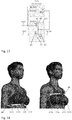
Fig. 18 shows the sensor device comprising a garment including the master and the cooperative sensors, according to an embodiment; -
Fig. 19 shows a variant of the sensor device comprising a garment; and -
Fig. 20 shows another variant of the sensor device comprising a garment. -
Fig. 1 illustrates schematically a sensor device for potential and/or impedance measurements on asurface 50 of abody 104 of a user, according to an embodiment. The sensor device comprises at least afirst cooperative sensor 101L connected to amaster 100 by a first one-wire connector 102L and asecond cooperative sensor 101R connected to themaster 100 by a second one-wire connector 102R. Eachcooperative sensor current electrode 51 and apotential electrode 54 destined to be in contact with asurface 50 of thebody 104 when the sensor device is worn by the user. -
Fig. 2 shows the sensor device according to a possible embodiment. Themaster 100 comprises a mastercurrent source 40 configured to circulate a master current "j" 47 in theconductors current electrode 51 of the first andsecond cooperative sensors body 104, when thecooperative sensors surface 50 of thebody 104. - As suggested by
Figs. 1 and 2 , each of thecooperative sensors master 100 can be distinct physical entities cooperating with each other via theconductors master 100 can be arranged with at least one of thecooperative sensors Fig. 3 where onecooperative sensor 101R is arranged with themaster 100 in a single housing. In this configuration, thecooperative sensors conductor - As shown in
Fig. 2 , eachcooperative sensor - In one aspect, the powering frequency band can be about 1 MHz or greater.
- In one aspect, the harvesting device comprises a harvesting voltage source 49 having a harvesting transfer function "H" 48 of the
master current 47. The function "H" may be for instance u0 -sign(j), where uo is a constant and j themaster current 47. - In another aspect, the
master 100 can be configured to measure a biopotential e of thebody 104 from amaster voltage E 41 across the mastercurrent source 40, when themaster voltage 41 is in a bio-potential frequency band. The bio-potential frequency band can be for instance between 0.5 Hz and 150 Hz. - In yet another aspect, the
master 100 is configured to measure a bio-impedance "z" of thebody 104 from themaster voltage 41 when the master current 47 is in a bio-impedance frequency band. The bio-impedance frequency band can be for instance between 49.5 kHz and 50.5 kHz. For the measurement of bio-impedance "z", thecurrent source 40, in addition to its component in the powering frequency band, has a component in the bio-impedance frequency band, for instance at about 50 kHz. Themaster voltage E 41 in the bio-impedance frequency band is then proportional to "z". - In an embodiment, the first
cooperative sensor 101L comprises asensor voltage source 46, anadder 44 and acontroller 45 having a transfer function -G. Theadder 44 is configured to sum acontroller voltage v 42 to a transfer signal d provided by atransfer voltage source 43 and input the sum in thecontroller 45. Thecontroller 45 is configured to set thecontroller voltage 42 equal to the opposite of the transfer signal d and to output a voltage u of thesensor voltage source 46. The secondcooperative sensor 101R in the embodiment shown inFig. 2 does not comprise the transfer voltage source 43 (transfer signal d = 0). - The
electrode potential 52 under thepotential electrode 54 can be considered "0" beyond the electrode-potential frequency band, e.g., < 0.05 Hz. The transfer signal d can be set to "0" in the bio-potential and bio-impedance frequency bands. - In one aspect, the transfer function -G of the
controller 45 can be chosen such that the rejection frequency band of a control loop of thecontroller 45 is maximal in the bio-potential and bio-impedance frequency bands (|G| ≫ 1), but minimal in the powering frequency band (|G| < 1). - If in addition the transfer function -G of the
controller 45 can be chosen such that the rejection frequency band of the control loop is also maximal (|G| ≫ 1) in the communication frequency band, e.g., from 150 to 49.5 kHz, such that themaster voltage 41 also includes the transfer signal d. Therefore, the communication frequency band can optionally be used to transfer signals d other than bio-potential and bio-impedance signals. For example, the transfer signals d can be used to transfer signals provided by optical sensors (e.g., photo-plethysmography, used for instance for non-occlusive blood pressure, oBPM®, pulse oximetry, etc.), acoustic sensors (e.g., phonogram, for instance for heart, lung, or digestive-track sounds, voice, snore, groan, etc.), temperature sensors (skin temperature), chemical sensors (sweat composition), impedance sensors (EDA, i.e., electrodermal activity also known as GSR, i.e., galvanic skin response), etc. - In the configuration of the
harvesting device 48, 49 as shown inFig. 2 , the master current 47 powering thecooperative sensor current electrode 51 and not via thepotential electrode 54. Any unexpected voltage disturbance the harvester may produce in the bio-potential, bio-impedance, or communication frequency bands is rejected by thecontroller 45. Theharvesting device 48, 49 could also be arranged otherwise, for instance, directly on theconnector sensor voltage source 46. -
Fig. 4 shows a simplified model of the metrological functions of the circuit ofFig. 2 . The purpose of thecontroller 45 inFig. 2 is to virtually suppresses theelectrode impedance 53. This is symbolized with the pass-throughcircuit 34. With the pass-throughcircuit symbol 34, the communication of transfer signal d is equivalent to a voltage source with voltage d. Assuming that theelectrode voltage 52 is negligible, themaster voltage 41 corresponds to equation (1) for the bio-potential, bio-impedance, or communication frequency bands:
- The bio-potential signal e, bio-impedance signal z and the communication signal d (or transfer signal d) can thus be easily extracted from the
master voltage E 41 by filtering. -
Fig. 5 shows the sensor device according to another embodiment. In addition to the sensor device circuit shown inFig. 2 , thecooperative sensor Fig. 5 further comprises alogic circuit L 31 that is clocked from the rising and/or falling edges of master current 47. The master current 47 can comprise a square wave at 1 MHz, i.e., periods of 1 µs. By replacing a 1 µs period by two 0.5 µs periods (or two 1 µs periods by one 2 µs period), one can associate a different state for the 1 µs period (e.g., "0") and another for the two 0.5 µs period (e.g., "1"). Therefore, a stream of bits can be sent from themaster 100 to thecooperative sensors logic circuit 31 of eachcooperative sensor cooperative sensors - The sensor device in
Fig. 5 further comprises a sensor current source i 30 configured to inject a sensor current i into the electrode impedance 53' of thepotential electrode 54. The sensor current i may be a square wave at 500 Hz so that the resulting voltage across the electrode impedance 53' is part of thebio-potential signal E 41, e.g., sampled at 1 kHz. Simple post filtering can extract from the bio-potential signal E the bio-potential e and the voltage across the electrode impedance 53' which is proportional to the electrode impedance 53'. It is useful to know the electrode impedance 53' to assess the quality of the electrode contact with the body surface 50 (the lower the electrode impedance 53', the better). The electrode impedance 53' may also be used in advance filtering to remove the electrode voltage 52' from thebio-potential signal 41, which variations are assumed linked to variations of the electrode impedance 53'. -
Fig. 6 represents a possible way to combine severalcooperative sensors first connector 102L).Fig. 6 shows threecooperative sensors connector 102, but other number of sensors is possible. Also, a plurality ofcooperative sensors second connector 102R). With more than the pair ofcooperative sensors body 104 with a simple circuit is not unique (the body is in reality a continuum of impedance and voltage source that can be rigorously modelled with a Thevenin equivalent only for two cooperative sensors). Therefore, the body model ofFig. 6 (which is not and cannot be just an extension of that of the previous figures) redefine e and z so to be modelled below each sensor (instead of between a pair of sensors). - Each
cooperative sensor capacitance 33. Thecapacitance 33 can serve to substantially equally distributes the mastercurrent j 47 between thecooperative sensors capacitance 33 can be further configured to average biopotentials "e", bio-admittances (y = 1/z, i.e., i.e., bio-admittances y are the inverse of their corresponding bio-impedances z) and a transfer signal d from the plurality of thecooperative sensors master 100 by asame connector 102, when thecooperative sensors body surface 50. For accurate averaging of bio-potentials e, e', e", bio-admittances y, y', y", and transmitted signals d, d', d", the impedance of the capacitances C, C', C" for eachcooperative sensor - The plurality of
cooperative sensors same connector 102 can transmit their respective transfer signal d on different channels, for instance time slots for time multiplexing or frequency bands for frequency multiplexing. Any transmittedsignal d 43 can then be recovered from themaster voltage 41 with a gain inversely proportional to the number ofcooperative sensors body surface 50. Additional cooperative sensors allow more channels and access to different positions, still with only two connections to themaster 100. - For each
cooperative sensor capacitance C 33, equal for all cooperative sensors 101a, 101b) corresponds to equation (2):
where N is the number ofcooperative sensors same connector 102 and (e) the average of all bio-potentials e, e', e" of thecooperative sensors - The voltage source d'46 can be used in the bio-impedance frequency band to induce the current j', according to equation (3):

where ω is the angular pulsation used for the bio-impedance measurement and i is the unit imaginary number. If two voltage sources d' and d" 46 work in opposition, the disturbance on themaster voltage E 41 can be minimized. The above equations assume that the capacitances C, C', C", are equal and the bio-impedance z, z', z", negligible. If these assumptions cannot be made, the equations are more complex, but can still be exactly solved for the bio-potentials e, e', e", and the bio-impedances z, z', z". - The capacitance voltage signal E' (or E") of a given cooperative sensor 101', (or 101", respectively) can be sent to the
master 100 via the transfer signal d' (or d", respectively), provided that a modulation is performed so that the transfer signal d' (or d", respectively) uses another frequency band.Fig. 7 shows the sensor device according to an embodiment wherein eachcooperative sensor 101', 101" comprises amodulator 32 configured to modulate the capacitance voltage E' (or E", respectively) across thecapacitance 33 with a carrier m' (or m", respectively) and output the transfer signals 43. In case of amplitude modulation (AM), a simple multiplication between the capacitance voltage signal E' and the carrier m' is required to obtain the transfer signals d' 43, i.e., d' = m' E'. -
Fig. 8 shows the complete circuit diagram of the sensor device ofFig. 7 . - An implementation example of the second
cooperative sensor 101R ofFig. 2 (i.e., with d = 0, or without the transfer voltage source 43) is shown inFig. 9 . Theresistances 63 and 64 provide a voltage divider between the positive and negative power-supply terminals of anoperational amplifier 60. Theresistances 63 and 64 define a potential between the positive and negative power-supply terminals, in the middle if they are equal. Theoperational amplifier 60 performs the functions ofadder 44, controller -G (45), andvoltage source 46. Twodiodes 65 and 66 together with the energy-storage capacitance voltage sources 46 and 49 are combined since the output of theoperational amplifier 60 is connected to the common terminal of the two energy-storage capacitances current electrode 53. Theresistances 63 and 64 also help to divide themaster voltage E 41 in the powering frequency band substantially equally between the first and secondcooperative sensors cooperative sensors current source 40 to reach saturation. Theresistance 67 is optional, but may help to get stability, since operational amplifiers are usually not designed to drive capacitances due to the compensation of their middle stage behaving as integrator. An amplifier without this internal integrator would be intrinsically more stable to drive a capacitive load. -
Fig. 10 shows a possible configuration of theoperational amplifier 60 ofFig. 9 . Theoperational amplifier 60 comprises a differential pair of the first stage with output as current source controlled with difference of inputs (in this case, theresistance 67 is omitted). -
Fig. 11 shows an implementation example of the cooperative sensor 101' corresponding to the sensor 101' ofFig. 8 . The sensorcurrent source 30 ofFig. 5 is implemented as a square wave (at, e.g., 500 Hz) produced by the LOGIC 31 (behaving with its output as voltage source) in series with the resistance 20 (a voltage source in series with an impedance is the Thevenin equivalent of a current source in parallel with the same impedance). The output resistance of the sensorcurrent source 30 ofFig. 5 is theresistance 20 magnified by G+1 since thepotential electrode 54 is a virtual ground (negative input of operational amplifier). The capacitance 21 makes the current-source output impedance higher for lower frequencies and ensures that no direct current flows across thebody 104. The capacitance voltage E' across thecapacitance 33 is low-pass filtered by theresistance 17 andcapacitance 18 such as to isolate the bio-potential part with enough antialiasing filtering to be sampled/modulated byswitch 23. A band-passfilter comprising resistance 19, capacitance 22,resistances 28, 29, andcapacitances -
Fig. 12 shows an alternative implementation of themaster 100, wherein the mastercurrent source 40 comprising a voltage source u 16 in series with acapacitance 15. -
Fig. 13 shows another alternative implementation of themaster 100 featuring two one-wire connectors same voltage source 16 via twocapacitances 15 and 15'. The master voltages 41 and 41' are measured across thecapacitances 15 and 15'. If a current j or j' has to be used for bio-impedance measurement, a mastercurrent source 40 or 40' can be added. -
Fig. 14 shows yet another alternative implementation of themaster 100. Here, amicrocontroller µC 12 plays the role of voltage source 16 (seeFig. 12 ), e.g., with a square wave at 1 MHz as digital signal at theconnector 102R. Theresistance 11 andcapacitance 10 as low-pass filter provide a reference for theinstrumentation amplifier 9 which is connected to an ADC (analogue-to-digital converter) of themicrocontroller 12. The positive terminal of theinstrumentation amplifier 9 is connected to thewire 102L for measuring themaster voltage E 41. Theresistance 14 allows themicrocontroller 12 to generate with a digital signal a square-wave current j, e.g., at 50 kHz, for the bio-impedance measurement at this frequency. Thecapacitance 13 increases the output impedance of the mastercurrent source 40 at low frequencies as well as prevents any direct current to flow across thebody 104. The shield for the master housing is connected to ground, as shown inFig. 14 . - In yet another alternative implementation of the
master 100 shown inFig. 15 , the generation of powering and bio-impedance currents j uses a push-pull approach. Thecapacitance 15 is now on bothconnectors output resistance 14 of the mastercurrent source 40. Therefore, both powering and bio-impedance current are generated by digital signals from themicrocontroller 12 with opposite phase for the twoconnectors current source 40. Note that thecapacitance 13 is not doubled to fix the master potential with respect to the body at 0 Hz. The drawback of this approach is that theinstrumentation amplifier 9 has a large voltage at powering frequency, requiring a good filter to avoid aliasing. The shield for the master housing is connected toconnector 102L (or toconnector 102R) as shown inFig. 15 . -
Fig. 16 shows how the sensor device can be used withconventional electronics 100c destined to measure bio-potential and bio-impedance (voltage E and current source j) with gel electrodes. Instead of gel electrodes, the bi-electrodecooperative sensors Fig. 9 with the twoelectrodes 54 and 51) are used with amaster 100 connected to the conventional electronics in the way shown inFig. 16 . - Another example is shown in
Fig. 17 where the extension of a conventional ECG electronics with a neutral electrode N (also called RL, i.e., right-leg electrode) originally designed with gel electrodes is depicted. Acapacitance 41 and aconnector 102L is used per electrode, except for the neutral electrode which is connected to one terminal of thevoltage source 16, the other being connected to theconnector 102R. -
Fig. 18 shows that the sensor device described herein can be deployed as a strap similar to conventional heartrate straps, with the central electronics (master) 100 typically in the middle and connecting theconnectors master 100 and thecooperative sensors connectors garment 80. - The sensor device can be used as an enhanced chest strap. No shield is needed to measure possible signals with good quality, even if the connectors are long. Long connectors allow, for instance, to have a front zipper with one of the connectors reaching the other side by the body back.
- The
master 100 can be connected to the strap with only two snap connectors, as conventional chest straps, which is considered as an advantage as compared to more (connecting) snaps (cheaper, smaller, easier to snap). - The sensor device allows the measurement of bio-impedance with a two-connector solution as if it was measured with four-connector solution, i.e., with the tetrapolar method (two electrodes for current injection and two electrodes for potential measurement).
- The remotely powered active bi-electrode 101L and 101R allows for higher quality measurement of bio-potentials (ECG) especially when dry (i.e., unwetted), in motion, or in electromagnetically disturbed environments. Moreover, four-electrode bio-impedance can also be measured, for instance to derive respiration rate, tidal amplitude, respiratory volume, etc. The
cooperative sensors cooperative sensors -
Fig. 19 shows a variant, where thecooperative sensors Cooperative sensors cooperative sensors cooperative sensors sensors master 100 can be part of a necklace and if wireless communication is desired, there is no issue to have the antenna at this position. -
Fig. 20 shows another variant where eachcooperative sensor sensor part 101 including the current andpotential electrodes counterpart 82. Thecounterpart 82 can be attachable to an external side of thegarment 80 and configured to attach thesensor part 101 on an internal side of thegarment 80 such that the current andpotential electrodes body surface 50 when the garment is worn by the user. - The
cooperative sensors counterpart 82 used as contact with theconductive parts cooperative sensors - The
counterpart 82 can be attached to thesensor part 111 by using apin 85. Thepin 85 can also be used to connect thesensor part 111 to theconnector counterpart 82. - This configuration of the
cooperative sensor sensor part 111 andcounterpart 82 may be obtained with magnets or any type of fastening means. Thepin 85 can be in the center of thesensor part 111 as shown inFig. 20 , but other configurations are possible. For example, three pins can be used at the periphery of thesensor part 111. The placement and mating of thecooperative sensor garment 80 may be done with the undershirt or bra unworn from landmarks placed on the undershirt or bra when worn. Such landmarks may be, e.g., stickers or ink/paint, or directly thecounterpart 82 with pressure-sensitive adhesive. The undershirt or bra can be washed with thesensors sensor part 111 can include a chip (IC, integrated circuit) 81.Such sensor part 111 are low-cost and specific for a given user. The twoelectrodes Figure 20 . They can also comprise two side-by-side electrodes. -
- 9
- instrumentation amplifier
- 10
- capacitance for low-pass filter for reference potential
- 11
- resistance for low-pass filter for reference potential
- 12
- microcontroller
- 13
- capacitance
- 14
- output resistance of
current source 40 - 15
- capacitance
- 16
- voltage source u
- 17
- resistance for antialiasing low-pass filter
- 18
- capacitance for antialiasing low-pass filter
- 19
- resistance for low-pass part of transferred-signal band-pass filter (1 of m')
- 20
- resistance to convert voltage source to
current source 30 - 21
- capacitance to increase output impedance of
current source 30 in biopotential frequency band - 22
- capacitance for high-pass part of transferred-signal band-pass filter
- 23
- modulation switch
- 26, 27
- capacitance for low-pass part of transferred-signal band-pass filter
- 28, 29
- resistance for high-pass part of transferred-signal band-pass filter
- 30
- sensor current source
- 31, L
- logic circuit
- 32
- modulator
- 33, C, C', C"
- capacitance
- 34
- pass-through circuit
- 40, 40'
- master current source
- 41, 41',
- master voltage E
- 42
- controller voltage V
- 43
- transfer voltage source
- 44
- adder
- 45
- controller, -G
- 46
- sensor voltage source
- 47
- master current
- 48
- harvesting transfer function
- 49
- harvesting voltage source
- 50
- skin
- 51
- current electrode
- 52, 52'
- electrode potential, half-cell potential
- 53, 53'
- electrode impedance
- 54, 54'
- potential electrode
- 60
- operational amplifier
- 61, 62
- energy-storage capacitance
- 63, 64
- resistances of voltage divider
- 65, 66
- rectifier diode
- 80
- underwear
- 81
- electronics of cooperative sensor
- 82
- fastener and back contact, counterpart
- 85
- pin
- 100
- master
- 100c
- conventional electronics
- 101
- cooperative sensor
- 101', 101"
- cooperative sensor
- 101L
- first cooperative sensor
- 101R
- second cooperative sensor
- 102
- connector
- 102L, 102L'
- first connector
- 102R
- second connector
- 104
- body
- 111
- sensor part
- 41
- capacitance (
Fig. 16 ) - d, d', d"
- transfer signal
- e, e', e"
- bio-potential, bio-voltage
- E
- voltage to measure
- E
- capacitance voltage
- G
- controller transfer function
- H
- harvester function
- i
- current
- IC
- integrated circuit
- J, j', j"
- current
- m
- carrier
- µC
- microcontroller
- R
- relative to right 1-wire bus
- u
- voltage
- v
- voltage, potential
- y
- bio-admittance, equal to 1/z
- z, z', z"
- bio-impedance
Claims (16)
- Sensor device for potential and/or impedance measurements on a body (104) of a user, comprising a master (100) and at least a first cooperative sensor (101L) and a second cooperative sensor (101R), each cooperative sensor (101L, 101R) being connected to the master (100) by a one-wire connector (102L, 102L);
each cooperative sensor (101L, 101R) comprising a current electrode (51) and a potential electrode (54) destined to be in contact with a surface (50) of the body (104);
the master (100) comprising a master current source (40) configured to circulate a master current j (47) in the one-wire connector (102L, 102L), the current electrode (51) of said at least first and second cooperative sensors (101L, 101R) and the body (104), when the cooperative sensors (101L, 101R) are in contact with a surface (50) of the body (104);
each cooperative sensor (101L, 101R) comprising a harvesting device configured to harvest energy from the circulating master current (47) in a powering frequency band. - The sensor device according to claim 1,
wherein the harvesting device comprises a harvesting voltage source (49) with voltage determined by a harvesting transfer function H (48) from the master current (47). - The sensor device according to claim 1 or 2,
wherein the master (100) is configured to measure a biopotential (e) of the body (104) from a master voltage (41) across the master current source (40), the master voltage (41) being in a bio-potential frequency band. - The sensor device according to claim 3,
wherein the master (100) is configured to measure a bio-impedance (z) of the body (104) from the master voltage (41) when the master current (47) is in a bio-impedance frequency band. - The sensor device according to any one of claims 1 to 4,
wherein at least one of the cooperative sensors (101L, 101R) comprises a sensor voltage source (46), an adder (44) and a controller (45) having a transfer function -G;
the adder (44) being configured to sum a voltage (42) to a transfer signal (d) and input the sum in the controller (45);
wherein the controller (45) is configured to set the voltage (42) equal to the opposite of the transfer signal (d) and to output a voltage (u) of the voltage source (46). - The sensor device according to claims 3, 4 and 5,
wherein the transfer function -G is configured such that a rejection frequency band of a control loop of the controller (45) is maximal in the bio-potential (e) and/or bio-impedance and minimal in the powering frequency band. - The sensor device according to claims 3, 4 and 5 or claim 6,
wherein the transfer function -G is further configured such that a rejection frequency band of the control loop of the controller (45) is maximal in a communication frequency band; and
wherein the master voltage (41) further includes the transfer signal (d) such that the signals other than bio-potential and bio-impedance signals can be acquired by the master (100). - The sensor device according to any one of claims 1 to 7,
wherein the cooperative sensor (101L, 101R) comprises a logic circuit (31) clocked from the edges of master current 47. - The sensor device according to any one of claims 1 to 8,
wherein each cooperative sensor (101L, 101R) comprises a sensor current source (30) configured to inject a sensor current (i) into an electrode impedance (53') of the potential electrode (54). - The sensor device according to any one of claims 1 to 9, comprising a plurality of the first cooperative sensor (101L) and/or the second cooperative sensor (101R).
- The sensor device according to claim 10,
wherein each cooperative sensor (101L, 101R) comprises a capacitance (33) configured to average biopotentials (e), bio-admittances (y) and a transfer signal (d) from the plurality of first and/or second cooperative sensors (101L, 101R) connected to the master (100) by a same one-wire connector (102L, 102L). - The sensor device according to claim 11,
wherein each cooperative sensor (101L, 101R) comprises a modulator (32) configured to modulate a capacitance voltage (E) across the capacitance (33) with a carrier (m) and output the transfer signals (d). - The sensor device according to claim 12,
wherein the multiplier (32) is configured to perform amplitude modulation between the capacitance voltage (E) and the carrier (m). - The sensor device according to any one of claims 1 to 13, comprising a garment (80) including the master (100) and the cooperative sensors (101L, 101R) and wherein the one-wire connector (102L, 102L) comprises conductive textile of the garment.
- The sensor device according to claim 14,
wherein each cooperative sensor (101L, 101R) comprises a sensor part (111) including the current and potential electrodes (51, 54) and a counterpart (82), the counterpart (82) being attachable to an external side of the garment (80) and configured to attach the sensor part (111) on an internal side of the garment (80) such that the current and potential electrodes (51, 54) are in contact the body surface (50) when the garment is worn by the user. - The sensor device according to claims 1, 3 and 7
wherein the powering frequency band is about 1 MHz or greater, the bio-potential frequency band is between 0.5 Hz and 150 Hz, the bio-impedance frequency band is between 49.5 kHz and 50.5 kHz, and the rejection frequency band is between 1 kHz and 49.5 kHz.
Priority Applications (4)
| Application Number | Priority Date | Filing Date | Title |
|---|---|---|---|
| EP20182601.3A EP3928692A1 (en) | 2020-06-26 | 2020-06-26 | Sensor device for potential and impedance measurements |
| EP21155816.8A EP3928694A1 (en) | 2020-06-26 | 2021-02-08 | Sensor circuit device for measuring a bio-potential or a bio-impedance |
| US17/356,903 US12478278B2 (en) | 2020-06-26 | 2021-06-24 | Sensor device for potential and impedance measurements |
| US17/649,804 US12433501B2 (en) | 2020-06-26 | 2022-02-03 | Sensor circuit device for measuring a bio-potential or a bio-impedance |
Applications Claiming Priority (1)
| Application Number | Priority Date | Filing Date | Title |
|---|---|---|---|
| EP20182601.3A EP3928692A1 (en) | 2020-06-26 | 2020-06-26 | Sensor device for potential and impedance measurements |
Publications (1)
| Publication Number | Publication Date |
|---|---|
| EP3928692A1 true EP3928692A1 (en) | 2021-12-29 |
Family
ID=71266326
Family Applications (2)
| Application Number | Title | Priority Date | Filing Date |
|---|---|---|---|
| EP20182601.3A Pending EP3928692A1 (en) | 2020-06-26 | 2020-06-26 | Sensor device for potential and impedance measurements |
| EP21155816.8A Pending EP3928694A1 (en) | 2020-06-26 | 2021-02-08 | Sensor circuit device for measuring a bio-potential or a bio-impedance |
Family Applications After (1)
| Application Number | Title | Priority Date | Filing Date |
|---|---|---|---|
| EP21155816.8A Pending EP3928694A1 (en) | 2020-06-26 | 2021-02-08 | Sensor circuit device for measuring a bio-potential or a bio-impedance |
Country Status (2)
| Country | Link |
|---|---|
| US (2) | US12478278B2 (en) |
| EP (2) | EP3928692A1 (en) |
Families Citing this family (3)
| Publication number | Priority date | Publication date | Assignee | Title |
|---|---|---|---|---|
| US11047821B2 (en) * | 2018-05-31 | 2021-06-29 | Analog Devices International Unlimited Company | Bio-impedance and contact impedances measurement |
| DE212020000509U1 (en) | 2019-01-14 | 2021-09-30 | Analog Devices International Unlimited Company | Multi-sensor device for health monitoring |
| CN115201541B (en) * | 2022-08-01 | 2026-02-13 | 上海艾为电子技术股份有限公司 | A detection circuit, a driving circuit, a chip, an electronic device, and a detection method. |
Citations (6)
| Publication number | Priority date | Publication date | Assignee | Title |
|---|---|---|---|---|
| EP2101408A1 (en) | 2008-03-11 | 2009-09-16 | CSEM Centre Suisse d'Electronique et de Microtechnique SA Recherche et Développement | Floating front-end amplifier and one-wire measuring devices |
| EP2294979A1 (en) * | 2009-09-14 | 2011-03-16 | Imec | Method and electronic medical device for simultaneously measuring and impedance and a biopotential signal |
| EP2567657A1 (en) * | 2011-09-07 | 2013-03-13 | CSEM Centre Suisse d'Electronique et de Microtechnique SA | Synchronization and communication bus for biopotential and bioimpedance measurement systems. |
| EP2727528A1 (en) * | 2012-11-05 | 2014-05-07 | CSEM Centre Suisse d'Electronique et de Microtechnique SA | Method for bio impedance measurement |
| EP2803315A1 (en) | 2013-05-15 | 2014-11-19 | Polar Electro Oy | Heart activity sensor structure |
| EP2886049A1 (en) * | 2013-12-20 | 2015-06-24 | CSEM Centre Suisse d'Electronique et de Microtechnique SA | Measurement device for measuring bio-impedance and/or a bio-potential of a human or animal body |
Family Cites Families (6)
| Publication number | Priority date | Publication date | Assignee | Title |
|---|---|---|---|---|
| US7559902B2 (en) * | 2003-08-22 | 2009-07-14 | Foster-Miller, Inc. | Physiological monitoring garment |
| US20150201858A1 (en) * | 2008-08-15 | 2015-07-23 | Global Cardiac Monitors, Inc. | Diagnostic device for remote sensing and transmitting biophysiological signals |
| WO2018053467A1 (en) * | 2016-09-19 | 2018-03-22 | William Marsh Rice University | Methods and systems of inducing hyperthermia in cancer cells |
| FI20175817A1 (en) * | 2017-09-14 | 2019-03-15 | Clothing Plus Mbu Oy | Electrode construction for measuring electrical signals |
| CN111134674B (en) * | 2018-11-09 | 2021-10-08 | 上海交通大学 | Bioelectrical impedance tomography system based on frequency division multiplexing data compression technology |
| EP3831289B1 (en) | 2019-12-05 | 2023-05-31 | CSEM Centre Suisse D'electronique Et De Microtechnique SA | Remotely powered cooperative sensor system |
-
2020
- 2020-06-26 EP EP20182601.3A patent/EP3928692A1/en active Pending
-
2021
- 2021-02-08 EP EP21155816.8A patent/EP3928694A1/en active Pending
- 2021-06-24 US US17/356,903 patent/US12478278B2/en active Active
-
2022
- 2022-02-03 US US17/649,804 patent/US12433501B2/en active Active
Patent Citations (7)
| Publication number | Priority date | Publication date | Assignee | Title |
|---|---|---|---|---|
| EP2101408A1 (en) | 2008-03-11 | 2009-09-16 | CSEM Centre Suisse d'Electronique et de Microtechnique SA Recherche et Développement | Floating front-end amplifier and one-wire measuring devices |
| EP2101408B1 (en) | 2008-03-11 | 2012-05-16 | CSEM Centre Suisse d'Electronique et de Microtechnique SA - Recherche et Développement | Floating front-end amplifier and one-wire measuring devices |
| EP2294979A1 (en) * | 2009-09-14 | 2011-03-16 | Imec | Method and electronic medical device for simultaneously measuring and impedance and a biopotential signal |
| EP2567657A1 (en) * | 2011-09-07 | 2013-03-13 | CSEM Centre Suisse d'Electronique et de Microtechnique SA | Synchronization and communication bus for biopotential and bioimpedance measurement systems. |
| EP2727528A1 (en) * | 2012-11-05 | 2014-05-07 | CSEM Centre Suisse d'Electronique et de Microtechnique SA | Method for bio impedance measurement |
| EP2803315A1 (en) | 2013-05-15 | 2014-11-19 | Polar Electro Oy | Heart activity sensor structure |
| EP2886049A1 (en) * | 2013-12-20 | 2015-06-24 | CSEM Centre Suisse d'Electronique et de Microtechnique SA | Measurement device for measuring bio-impedance and/or a bio-potential of a human or animal body |
Non-Patent Citations (4)
| Title |
|---|
| MICHAEL RAPIN ET AL: "Cooperative sensors: a new wired body-sensor-network approach for wearable biopotential measurement", PROCEEDINGS OF THE 5TH EAI INTERNATIONAL CONFERENCE ON WIRELESS MOBILE COMMUNICATION AND HEALTHCARE, "TRANSFORMING HEALTHCARE THROUGH INNOVATIONS IN MOBILE AND WIRELESS TECHNOLOGIES", 1 January 2015 (2015-01-01), XP055693487, ISBN: 978-1-63190-088-4, DOI: 10.4108/eai.14-10-2015.2261683 * |
| MICHAEL RAPIN: "A Wearable Sensor Architecture for High-Quality Measurement of Multilead ECG and Frequency-Multiplexed EIT", 9 November 2018 (2018-11-09), XP055737302, Retrieved from the Internet <URL:https://www.research-collection.ethz.ch/bitstream/handle/20.500.11850/302712/181105_RapinThesis_Final.pdf?sequence=1&isAllowed=y> [retrieved on 20201006], DOI: 10.3929/ethz-b-000302712 * |
| RAPIN M ET AL: "Cooperative dry-electrode sensors for multi-lead biopotential and bioimpedance monitoring", PHYSIOLOGICAL MEASUREMENT, INSTITUTE OF PHYSICS PUBLISHING, BRISTOL, GB, vol. 36, no. 4, 23 March 2015 (2015-03-23), pages 767 - 783, XP020282136, ISSN: 0967-3334, [retrieved on 20150323], DOI: 10.1088/0967-3334/36/4/767 * |
| SUNYOUNG KIM ET AL: "A 2.4 A continuous-time electrode-skin impedance measurement circuit for motion artifact monitoring in ECG acquisition systems", VLSI CIRCUITS (VLSIC), 2010 IEEE SYMPOSIUM ON, 1 June 2010 (2010-06-01), Piscataway, NJ, USA, pages 219 - 220, XP055737524, ISBN: 978-1-4244-5454-9, DOI: 10.1109/VLSIC.2010.5560290 * |
Also Published As
| Publication number | Publication date |
|---|---|
| US12478278B2 (en) | 2025-11-25 |
| US20210401317A1 (en) | 2021-12-30 |
| US20220248975A1 (en) | 2022-08-11 |
| EP3928694A1 (en) | 2021-12-29 |
| US12433501B2 (en) | 2025-10-07 |
Similar Documents
| Publication | Publication Date | Title |
|---|---|---|
| EP2101408B1 (en) | Floating front-end amplifier and one-wire measuring devices | |
| US12478278B2 (en) | Sensor device for potential and impedance measurements | |
| Chi et al. | Wireless non-contact EEG/ECG electrodes for body sensor networks | |
| Nemati et al. | A wireless wearable ECG sensor for long-term applications | |
| Thakor | Biopotentials and electrophysiology measurement | |
| US9662030B2 (en) | Electrocardiography device for garments | |
| CN202699135U (en) | A wireless wearable electrocardiogram chest belt based on non-contact electrodes | |
| KR20040081427A (en) | Wireless electrocardiograph system | |
| Besnoff et al. | Battery-free multichannel digital ECG biotelemetry using UHF RFID techniques | |
| CN102657524A (en) | Non-contact electrocardiogram sensor and application of non-contact electrocardiogram sensor | |
| US20190117100A1 (en) | Wearable Multi-Lead Diagnostic ECG Recording Device | |
| US20140213880A1 (en) | Magnetically connected electrode for measuring physiological signals | |
| EP2567657A1 (en) | Synchronization and communication bus for biopotential and bioimpedance measurement systems. | |
| US20020161309A1 (en) | Fiber optic power source for an electroencephalograph acquisition apparatus | |
| CN105708448A (en) | Information acquisition device | |
| Lacirignola et al. | Hardware design of a wearable ECG-sensor: Strategies implementation for improving CMRR and reducing noise | |
| Vuorinen et al. | Printed, skin-mounted hybrid system for ECG measurements | |
| US20140213883A1 (en) | Magnetically connected electrode for measuring physiological signals | |
| Nguyen et al. | Smart Mouthguard With Fabric Electrodes for Wireless Intraoral Electrooculogram Monitoring | |
| Lou et al. | Towards bioelectric signal-enabled human healthcare monitoring: state-of-the-art, design strategies, challenge, and future | |
| Srinivasulu et al. | An engineering perspective of external cardiac loop recorder: a systematic review | |
| Pfeiffer et al. | Motion-induced imbalance of contact impedance in ECG capture: Comparison of electrode materials in capacitive coupling | |
| Feng et al. | A design and implementation of an ambulatory electrocardiogram (ECG) acquisition circuit for emergency application | |
| US10966659B2 (en) | Multiple sensor wearable and portable non-invasive respiration monitoring instrumentation | |
| US20140213881A1 (en) | Magnetically connected electrode for measuring physiological signals |
Legal Events
| Date | Code | Title | Description |
|---|---|---|---|
| PUAI | Public reference made under article 153(3) epc to a published international application that has entered the european phase |
Free format text: ORIGINAL CODE: 0009012 |
|
| STAA | Information on the status of an ep patent application or granted ep patent |
Free format text: STATUS: THE APPLICATION HAS BEEN PUBLISHED |
|
| AK | Designated contracting states |
Kind code of ref document: A1 Designated state(s): AL AT BE BG CH CY CZ DE DK EE ES FI FR GB GR HR HU IE IS IT LI LT LU LV MC MK MT NL NO PL PT RO RS SE SI SK SM TR |
|
| B565 | Issuance of search results under rule 164(2) epc |
Effective date: 20201020 |
|
| STAA | Information on the status of an ep patent application or granted ep patent |
Free format text: STATUS: REQUEST FOR EXAMINATION WAS MADE |
|
| 17P | Request for examination filed |
Effective date: 20220623 |
|
| RBV | Designated contracting states (corrected) |
Designated state(s): AL AT BE BG CH CY CZ DE DK EE ES FI FR GB GR HR HU IE IS IT LI LT LU LV MC MK MT NL NO PL PT RO RS SE SI SK SM TR |
|
| STAA | Information on the status of an ep patent application or granted ep patent |
Free format text: STATUS: EXAMINATION IS IN PROGRESS |
|
| 17Q | First examination report despatched |
Effective date: 20250129 |
|
| GRAP | Despatch of communication of intention to grant a patent |
Free format text: ORIGINAL CODE: EPIDOSNIGR1 |
|
| STAA | Information on the status of an ep patent application or granted ep patent |
Free format text: STATUS: GRANT OF PATENT IS INTENDED |
|
| RIC1 | Information provided on ipc code assigned before grant |
Ipc: A61B 5/053 20210101AFI20260318BHEP Ipc: A61B 5/00 20060101ALI20260318BHEP Ipc: A61B 5/0531 20210101ALI20260318BHEP Ipc: A61B 5/282 20210101ALI20260318BHEP Ipc: A61B 5/0205 20060101ALN20260318BHEP Ipc: A61B 5/0535 20210101ALN20260318BHEP Ipc: A61B 5/0536 20210101ALN20260318BHEP Ipc: A61B 5/0537 20210101ALN20260318BHEP Ipc: A61B 5/291 20210101ALN20260318BHEP |
|
| INTG | Intention to grant announced |
Effective date: 20260401 |