EP3927974B1 - Single screw compressor - Google Patents
Single screw compressor Download PDFInfo
- Publication number
- EP3927974B1 EP3927974B1 EP20709663.7A EP20709663A EP3927974B1 EP 3927974 B1 EP3927974 B1 EP 3927974B1 EP 20709663 A EP20709663 A EP 20709663A EP 3927974 B1 EP3927974 B1 EP 3927974B1
- Authority
- EP
- European Patent Office
- Prior art keywords
- slide
- casing
- main rotor
- cut
- rotor
- Prior art date
- Legal status (The legal status is an assumption and is not a legal conclusion. Google has not performed a legal analysis and makes no representation as to the accuracy of the status listed.)
- Active
Links
Images



Classifications
-
- F—MECHANICAL ENGINEERING; LIGHTING; HEATING; WEAPONS; BLASTING
- F04—POSITIVE - DISPLACEMENT MACHINES FOR LIQUIDS; PUMPS FOR LIQUIDS OR ELASTIC FLUIDS
- F04C—ROTARY-PISTON, OR OSCILLATING-PISTON, POSITIVE-DISPLACEMENT MACHINES FOR LIQUIDS; ROTARY-PISTON, OR OSCILLATING-PISTON, POSITIVE-DISPLACEMENT PUMPS
- F04C28/00—Control of, monitoring of, or safety arrangements for, pumps or pumping installations specially adapted for elastic fluids
- F04C28/10—Control of, monitoring of, or safety arrangements for, pumps or pumping installations specially adapted for elastic fluids characterised by changing the positions of the inlet or outlet openings with respect to the working chamber
- F04C28/12—Control of, monitoring of, or safety arrangements for, pumps or pumping installations specially adapted for elastic fluids characterised by changing the positions of the inlet or outlet openings with respect to the working chamber using sliding valves
-
- F—MECHANICAL ENGINEERING; LIGHTING; HEATING; WEAPONS; BLASTING
- F04—POSITIVE - DISPLACEMENT MACHINES FOR LIQUIDS; PUMPS FOR LIQUIDS OR ELASTIC FLUIDS
- F04C—ROTARY-PISTON, OR OSCILLATING-PISTON, POSITIVE-DISPLACEMENT MACHINES FOR LIQUIDS; ROTARY-PISTON, OR OSCILLATING-PISTON, POSITIVE-DISPLACEMENT PUMPS
- F04C18/00—Rotary-piston pumps specially adapted for elastic fluids
- F04C18/48—Rotary-piston pumps with non-parallel axes of movement of co-operating members
- F04C18/50—Rotary-piston pumps with non-parallel axes of movement of co-operating members the axes being arranged at an angle of 90 degrees
- F04C18/52—Rotary-piston pumps with non-parallel axes of movement of co-operating members the axes being arranged at an angle of 90 degrees of intermeshing engagement type, i.e. with engagement of co-operating members similar to that of toothed gearing
-
- F—MECHANICAL ENGINEERING; LIGHTING; HEATING; WEAPONS; BLASTING
- F04—POSITIVE - DISPLACEMENT MACHINES FOR LIQUIDS; PUMPS FOR LIQUIDS OR ELASTIC FLUIDS
- F04C—ROTARY-PISTON, OR OSCILLATING-PISTON, POSITIVE-DISPLACEMENT MACHINES FOR LIQUIDS; ROTARY-PISTON, OR OSCILLATING-PISTON, POSITIVE-DISPLACEMENT PUMPS
- F04C3/00—Rotary-piston machines or pumps, with non-parallel axes of movement of co-operating members, e.g. of screw type
- F04C3/06—Rotary-piston machines or pumps, with non-parallel axes of movement of co-operating members, e.g. of screw type the axes being arranged otherwise than at an angle of 90 degrees
- F04C3/08—Rotary-piston machines or pumps, with non-parallel axes of movement of co-operating members, e.g. of screw type the axes being arranged otherwise than at an angle of 90 degrees of intermeshing engagement type, i.e. with engagement of co-operating members similar to that of toothed gearing
- F04C3/085—Rotary-piston machines or pumps, with non-parallel axes of movement of co-operating members, e.g. of screw type the axes being arranged otherwise than at an angle of 90 degrees of intermeshing engagement type, i.e. with engagement of co-operating members similar to that of toothed gearing the axes of cooperating members being on the same plane
Definitions
- This invention relates to a single screw compressor with a variable volume ratio (VR).
- VR variable volume ratio
- Screw compressors traditionally use slides to control the capacity of the compressor and/or the volume ratio of the compression process.
- Capacity control slides such as that shown in Figure 1 , conventionally operate in the axial plane along the rotor(s).
- the suction end of the slides delays the start of compression by opening a bypass port during the early rotation period of the main rotor, thereby effectively reducing the swept volume (capacity) of the compressor.
- the delivery port opening is delayed, thus maintaining approximately constant VR during most of the compression process.
- Variable frequency drives are now commonly used to provide capacity control of screw compressors. However the slides are retained to provide a variable volume ratio function.
- variable volume ratio slide An example of a variable volume ratio slide is shown in Figure 2 . This can be considered as a modification of the conventional capacity control slide. This is achieved by extending the suction end of the slide such that no bypass port to suction is opened during the full axial movement of the slide. The slide VR port is then designed to provide the varying volume ratio as the rotor flute opens to the discharge port via the slide VR port.
- the conventional VVR slide has the disadvantage that it must extend from the discharge port to the end of the rotor such that even when the slide is at the highest VR position (travel towards the discharge end of the rotor) the suction end of the rotor is sealed and no bypassing to suction can occur.
- This slide must have clearance in the slide bore if it is to move freely. This clearance provides a leakage path directly from discharge to suction and to a lesser extent intermediate pressure also sealed by the slide can leak to suction. This leakage occurs when the slide is at any position and results in an unwanted reduction in compressor efficiency.
- Figure 3 schematically shows the slide in place in the compressor and
- Figure 4 shows the slide leakage paths 1.
- Documents GB 1 555 329 A , GB 1 555 330 A , EP 2 444 671 A1 and WO 2017/203608 A1 disclose single screw compressors with long variable volume ratio slides, all of them disclosing a low volume ratio position where the slide is within the casing for the main rotor.
- Document GB 2 119 856 A discloses a single screw compressor with two slides for combined control of capacity and volume ratio, none of which slides has a cut-out, and being arranged in different positions not explicitly beyond the casing for the main rotor.
- the invention employs a simple two step arrangement, which can match the efficiency of a true fully modulating variable VR slide due to the reduced leakage effect.
- the present invention provides a single screw compressor comprising a main rotor and at least one gate rotor, a casing for the main rotor having a discharge port at a discharge end of the casing, and a slide slidable within a bore in the casing adjacent the main rotor, the slide having a cut-out between first and second sealing parts of the slide, the slide being slidable between a high volume ratio position where the cut-out is within the casing and provides a path to the discharge port, and a low volume ratio position where the slide is beyond the discharge end of the casing to provide a fixed discharge path in the bore of the casing.
- the first, i.e. upstream, sealing part of the rotor has a surface facing away from the cut-out that is substantially in a plane transverse to the axes of the slide and the main rotor. This is for ease of manufacture.
- the first, sealing part of the rotor has a surface facing away from the cut-out that is inclined to a plane transverse to the axes of the slide and the main rotor at an angle substantially the same as the main rotor pitch angle. This gives accurate VR control.
- Figure 5 shows a slide according to the invention having sealing parts 2, 4 and a cut-out 6.
- Figure 6 shows the slide of Figure 5 positioned in towards the main casing alongside the main rotor.
- the cut-out 6 provides an accurate high VR discharge port.
- Figure 7 shows how a lower VR is achieved.
- the slide is pulled out from the casing so that it is beyond the main rotor and thus the VR is formed from the port 8 remaining in the casing.
- the slide of Figures 5 to 7 is a simple slide.
- the higher VR slide discharge port provided by the cut-out 6 correctly aligns with the rotor flute, but when the slide is withdrawn beyond the rotor the remaining low VR fixed port does not match the true VR requirement.
- Figures 8 to 10 show an alternative slide which has the same high VR cut-out as the slide of Figures 5 to 7 . However this slide also has the correct low VR remaining in the casing when the slide is moved out of engagement beyond the rotor as shown in Figure 10 .
Landscapes
- Engineering & Computer Science (AREA)
- Mechanical Engineering (AREA)
- General Engineering & Computer Science (AREA)
- Applications Or Details Of Rotary Compressors (AREA)
Description
- This invention relates to a single screw compressor with a variable volume ratio (VR).
- Screw compressors traditionally use slides to control the capacity of the compressor and/or the volume ratio of the compression process.
- Capacity control slides, such as that shown in
Figure 1 , conventionally operate in the axial plane along the rotor(s). The suction end of the slides delays the start of compression by opening a bypass port during the early rotation period of the main rotor, thereby effectively reducing the swept volume (capacity) of the compressor. At the same time the delivery port opening is delayed, thus maintaining approximately constant VR during most of the compression process. - Variable frequency drives are now commonly used to provide capacity control of screw compressors. However the slides are retained to provide a variable volume ratio function.
- As operating conditions change, the required built in volume ratio needs to change to match these changing conditions, if optimum efficiency is to be achieved. An example of a variable volume ratio slide is shown in
Figure 2 . This can be considered as a modification of the conventional capacity control slide. This is achieved by extending the suction end of the slide such that no bypass port to suction is opened during the full axial movement of the slide. The slide VR port is then designed to provide the varying volume ratio as the rotor flute opens to the discharge port via the slide VR port. - The conventional VVR slide has the disadvantage that it must extend from the discharge port to the end of the rotor such that even when the slide is at the highest VR position (travel towards the discharge end of the rotor) the suction end of the rotor is sealed and no bypassing to suction can occur. This slide must have clearance in the slide bore if it is to move freely. This clearance provides a leakage path directly from discharge to suction and to a lesser extent intermediate pressure also sealed by the slide can leak to suction. This leakage occurs when the slide is at any position and results in an unwanted reduction in compressor efficiency.
Figure 3 schematically shows the slide in place in the compressor and -
Figure 4 shows theslide leakage paths 1. -
Documents GB 1 555 329 A GB 1 555 330 AEP 2 444 671 A1WO 2017/203608 A1 disclose single screw compressors with long variable volume ratio slides, all of them disclosing a low volume ratio position where the slide is within the casing for the main rotor.Document GB 2 119 856 A - It is an aim of the invention to eliminate this leakage path from discharge to suction and thereby to improve the base efficiency.
- The invention employs a simple two step arrangement, which can match the efficiency of a true fully modulating variable VR slide due to the reduced leakage effect.
- The present invention provides a single screw compressor comprising a main rotor and at least one gate rotor, a casing for the main rotor having a discharge port at a discharge end of the casing, and a slide slidable within a bore in the casing adjacent the main rotor, the slide having a cut-out between first and second sealing parts of the slide, the slide being slidable between a high volume ratio position where the cut-out is within the casing and provides a path to the discharge port, and a low volume ratio position where the slide is beyond the discharge end of the casing to provide a fixed discharge path in the bore of the casing.
- In one embodiment, the first, i.e. upstream, sealing part of the rotor, has a surface facing away from the cut-out that is substantially in a plane transverse to the axes of the slide and the main rotor. This is for ease of manufacture.
- In an alternative embodiment, the first, sealing part of the rotor, has a surface facing away from the cut-out that is inclined to a plane transverse to the axes of the slide and the main rotor at an angle substantially the same as the main rotor pitch angle. This gives accurate VR control.
- The invention will now be described in more detail, by way of example only, with reference to the accompanying drawings, in which;
-
Figure 1 shows the known capacity control slide discussed above; -
Figure 2 shows the known VR control slide discussed above; -
Figures 3 and 4 are views showing the known VR control slide and its leakage paths; -
Figure 5 shows a slide according to an embodiment of the invention; -
Figures 6 and7 show the slide ofFigure 5 at different positions in the compressor; -
Figure 8 shown a slide according to an alternative embodiment; and -
Figures 9 and 10 show the slide ofFigure 5 at different positions in the compressor. -
Figure 5 shows a slide according to the invention having sealingparts -
Figure 6 shows the slide ofFigure 5 positioned in towards the main casing alongside the main rotor. The cut-out 6 provides an accurate high VR discharge port. -
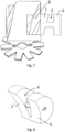
Figure 7 shows how a lower VR is achieved. The slide is pulled out from the casing so that it is beyond the main rotor and thus the VR is formed from theport 8 remaining in the casing. - The slide of
Figures 5 to 7 is a simple slide. The higher VR slide discharge port provided by the cut-out 6 correctly aligns with the rotor flute, but when the slide is withdrawn beyond the rotor the remaining low VR fixed port does not match the true VR requirement. -
Figures 8 to 10 show an alternative slide which has the same high VR cut-out as the slide ofFigures 5 to 7 . However this slide also has the correct low VR remaining in the casing when the slide is moved out of engagement beyond the rotor as shown inFigure 10 . - The simple slide of
Figures 5 to 7 is easier to produce and the VR compromise is less detrimental at the Low VR operating conditions than at higher VR conditions. The true VR slide ofFigures 8 to 10 will provide the highest efficiency.
Claims (3)
- A single screw compressor comprising a main rotor and at least one gate rotor, a casing for the main rotor having a discharge port (8) at a discharge end of the casing, and a slide slidable within a bore in the casing adjacent the main rotor, the slide having a cut-out (6) between first (2,2') and second (4) sealing parts of the slide,
characterised in that the slide is slidable between a high volume ratio position where the cut-out (6) is within the casing and provides a path to the discharge port (8), and a low volume ratio position where the slide is beyond the discharge end of the casing to provide a fixed discharge path in the bore of the casing. - A compressor according to claim 1, wherein the first, i.e. upstream, sealing part (2) of the slide, has a surface facing away from the cut-out (6) that is substantially in a plane transverse to the axes of the slide and the main rotor.
- A compressor according to claim 1, wherein the first, i.e. upstream, sealing part (2') of the slide, has a surface facing away from the cut-out (6) that is inclined to a plane transverse to the axes of the slide and the main rotor at an angle substantially the same as the main rotor pitch angle.
Applications Claiming Priority (2)
| Application Number | Priority Date | Filing Date | Title |
|---|---|---|---|
| GB1902468.6A GB2581526A (en) | 2019-02-22 | 2019-02-22 | Single screw compressor |
| PCT/GB2020/050405 WO2020169978A1 (en) | 2019-02-22 | 2020-02-20 | Single screw compressor |
Publications (2)
| Publication Number | Publication Date |
|---|---|
| EP3927974A1 EP3927974A1 (en) | 2021-12-29 |
| EP3927974B1 true EP3927974B1 (en) | 2024-01-24 |
Family
ID=65998894
Family Applications (1)
| Application Number | Title | Priority Date | Filing Date |
|---|---|---|---|
| EP20709663.7A Active EP3927974B1 (en) | 2019-02-22 | 2020-02-20 | Single screw compressor |
Country Status (9)
| Country | Link |
|---|---|
| US (1) | US12158147B2 (en) |
| EP (1) | EP3927974B1 (en) |
| JP (2) | JP7777449B2 (en) |
| CN (1) | CN113423954B (en) |
| AU (1) | AU2020225444B2 (en) |
| CA (1) | CA3127934A1 (en) |
| ES (1) | ES2975009T3 (en) |
| GB (1) | GB2581526A (en) |
| WO (1) | WO2020169978A1 (en) |
Families Citing this family (1)
| Publication number | Priority date | Publication date | Assignee | Title |
|---|---|---|---|---|
| GB2581526A (en) | 2019-02-22 | 2020-08-26 | J & E Hall Ltd | Single screw compressor |
Citations (1)
| Publication number | Priority date | Publication date | Assignee | Title |
|---|---|---|---|---|
| GB2119856A (en) * | 1982-05-13 | 1983-11-23 | Bernard Zimmern | Rotary positive-displacement fluid-machins |
Family Cites Families (21)
| Publication number | Priority date | Publication date | Assignee | Title |
|---|---|---|---|---|
| GB1555329A (en) * | 1975-08-21 | 1979-11-07 | Hall Thermotank Prod Ltd | Rotary fluid machines |
| GB1555330A (en) | 1978-03-21 | 1979-11-07 | Hall Thermotank Prod Ltd | Rotary fluid machines |
| SE442323B (en) * | 1984-05-11 | 1985-12-16 | Svenska Rotor Maskiner Ab | SCREW COMPRESSOR WITH TWO INDIVIDUALLY RELEASABLE CONTROL SLIDES |
| JPS6193294A (en) * | 1984-10-12 | 1986-05-12 | Daikin Ind Ltd | Capacity controlling device of screw compressor |
| FR2661457B1 (en) * | 1990-04-30 | 1992-08-21 | Zimmern Bernard | SLIDE COMPRESSOR WITH EQUALIZING SPRINGS. |
| GB0821275D0 (en) * | 2008-11-20 | 2008-12-31 | Aaf Mcquay Inc | Screw compressor |
| JP4645754B2 (en) * | 2009-06-15 | 2011-03-09 | ダイキン工業株式会社 | Screw compressor |
| JP5814606B2 (en) * | 2011-04-26 | 2015-11-17 | 三菱電機株式会社 | Screw compressor |
| US9057373B2 (en) * | 2011-11-22 | 2015-06-16 | Vilter Manufacturing Llc | Single screw compressor with high output |
| JP2013177868A (en) * | 2012-02-29 | 2013-09-09 | Daikin Industries Ltd | Screw compressor |
| WO2014192114A1 (en) * | 2013-05-30 | 2014-12-04 | 三菱電機株式会社 | Screw compressor and refrigeration cycle device |
| CN105782036A (en) * | 2014-12-25 | 2016-07-20 | 珠海格力节能环保制冷技术研究中心有限公司 | Compressor and internal volume ratio adjusting method for compressor |
| JP5943101B1 (en) * | 2015-02-10 | 2016-06-29 | ダイキン工業株式会社 | Screw compressor |
| DE102015006129A1 (en) * | 2015-05-09 | 2016-11-10 | Man Diesel & Turbo Se | screw machine |
| CN105508243B (en) * | 2016-01-19 | 2019-07-23 | 珠海格力电器股份有限公司 | Single screw compressor |
| EP3421800B1 (en) * | 2016-02-23 | 2020-03-25 | Mitsubishi Electric Corporation | Screw compressor and refrigeration cycle device |
| EP3425202B1 (en) * | 2016-03-01 | 2024-06-19 | Mitsubishi Electric Corporation | Screw compressor and refrigeration cycle device |
| CN109154455B (en) * | 2016-05-24 | 2021-06-11 | 三菱电机株式会社 | Refrigeration cycle device |
| JP2018009516A (en) | 2016-07-14 | 2018-01-18 | ダイキン工業株式会社 | Screw compressor |
| CN208089547U (en) * | 2017-09-30 | 2018-11-13 | 江森自控空调冷冻设备(无锡)有限公司 | A kind of guiding valve |
| GB2581526A (en) | 2019-02-22 | 2020-08-26 | J & E Hall Ltd | Single screw compressor |
-
2019
- 2019-02-22 GB GB1902468.6A patent/GB2581526A/en not_active Withdrawn
-
2020
- 2020-02-20 ES ES20709663T patent/ES2975009T3/en active Active
- 2020-02-20 CN CN202080014634.6A patent/CN113423954B/en active Active
- 2020-02-20 CA CA3127934A patent/CA3127934A1/en active Pending
- 2020-02-20 JP JP2021549429A patent/JP7777449B2/en active Active
- 2020-02-20 AU AU2020225444A patent/AU2020225444B2/en active Active
- 2020-02-20 US US17/431,709 patent/US12158147B2/en active Active
- 2020-02-20 WO PCT/GB2020/050405 patent/WO2020169978A1/en not_active Ceased
- 2020-02-20 EP EP20709663.7A patent/EP3927974B1/en active Active
-
2024
- 2024-05-20 JP JP2024081654A patent/JP2024105647A/en active Pending
Patent Citations (1)
| Publication number | Priority date | Publication date | Assignee | Title |
|---|---|---|---|---|
| GB2119856A (en) * | 1982-05-13 | 1983-11-23 | Bernard Zimmern | Rotary positive-displacement fluid-machins |
Also Published As
| Publication number | Publication date |
|---|---|
| JP7777449B2 (en) | 2025-11-28 |
| US12158147B2 (en) | 2024-12-03 |
| ES2975009T3 (en) | 2024-07-02 |
| JP2024105647A (en) | 2024-08-06 |
| CN113423954A (en) | 2021-09-21 |
| WO2020169978A1 (en) | 2020-08-27 |
| GB2581526A (en) | 2020-08-26 |
| JP2022521338A (en) | 2022-04-06 |
| AU2020225444A1 (en) | 2021-08-26 |
| GB201902468D0 (en) | 2019-04-10 |
| AU2020225444B2 (en) | 2025-07-10 |
| CA3127934A1 (en) | 2020-08-27 |
| CN113423954B (en) | 2023-06-30 |
| US20220136506A1 (en) | 2022-05-05 |
| EP3927974A1 (en) | 2021-12-29 |
Similar Documents
| Publication | Publication Date | Title |
|---|---|---|
| US5240389A (en) | Scroll type compressor | |
| US4261691A (en) | Rotary screw machine with two intermeshing gate rotors and two independently controlled gate regulating valves | |
| KR102196191B1 (en) | Positive-displacement machine according to the spiral principle, method for operating a positive-displacement machine, positive-displacement spiral, vehicle air-conditioning system and vehicle | |
| KR101235988B1 (en) | Variable capacity vane pump with force reducing chamber on displacement ring | |
| US4575323A (en) | Slide valve type screw compressor | |
| US20140234148A1 (en) | Scroll Compressor | |
| US4946362A (en) | Rotary screw compressor with a lift valve mounted in high pressure end wall | |
| CN102216619A (en) | Screw compressor | |
| TWI626380B (en) | Screw compressor and refrigeration cycle device with screw compressor | |
| GB2158882A (en) | Screw compressor | |
| US12158147B2 (en) | Slide valve of a single screw compressor | |
| GB2157370A (en) | Roots compressor | |
| US8579614B2 (en) | Scroll compressor with three discharge valves, and discharge pressure tap to back pressure chamber | |
| KR20170092044A (en) | Rotary compressor | |
| WO2020165561A1 (en) | Screw compressor | |
| CN116123093A (en) | Movable vortex disc assembly and vortex compressor with same | |
| EP3638907B1 (en) | Twin shaft pumps and a method of pumping | |
| US11125230B2 (en) | Scroll compressor having offset portion provided on discharge port to reduce backflow | |
| CN111828323A (en) | Variable capacity compressor | |
| US6149411A (en) | Variable flank relief for scroll wraps | |
| US7938634B2 (en) | Self-modulated scroll compressor with optimized built-in volume ratio | |
| KR960004247B1 (en) | Scroll compressor | |
| US11326602B2 (en) | Scroll compressor including end-plate side stepped portions of each of the scrolls corresponding to wall-portion side stepped portions of each of the scrolls | |
| US6203299B1 (en) | Capacity modulation for scroll compressors | |
| EP0162157A1 (en) | A screw compressor incorporating a slide valve |
Legal Events
| Date | Code | Title | Description |
|---|---|---|---|
| STAA | Information on the status of an ep patent application or granted ep patent |
Free format text: STATUS: UNKNOWN |
|
| STAA | Information on the status of an ep patent application or granted ep patent |
Free format text: STATUS: THE INTERNATIONAL PUBLICATION HAS BEEN MADE |
|
| PUAI | Public reference made under article 153(3) epc to a published international application that has entered the european phase |
Free format text: ORIGINAL CODE: 0009012 |
|
| STAA | Information on the status of an ep patent application or granted ep patent |
Free format text: STATUS: REQUEST FOR EXAMINATION WAS MADE |
|
| 17P | Request for examination filed |
Effective date: 20210804 |
|
| AK | Designated contracting states |
Kind code of ref document: A1 Designated state(s): AL AT BE BG CH CY CZ DE DK EE ES FI FR GB GR HR HU IE IS IT LI LT LU LV MC MK MT NL NO PL PT RO RS SE SI SK SM TR |
|
| DAV | Request for validation of the european patent (deleted) | ||
| DAX | Request for extension of the european patent (deleted) | ||
| P01 | Opt-out of the competence of the unified patent court (upc) registered |
Effective date: 20230525 |
|
| RAP1 | Party data changed (applicant data changed or rights of an application transferred) |
Owner name: DAIKIN INDUSTRIES, LTD. |
|
| GRAP | Despatch of communication of intention to grant a patent |
Free format text: ORIGINAL CODE: EPIDOSNIGR1 |
|
| STAA | Information on the status of an ep patent application or granted ep patent |
Free format text: STATUS: GRANT OF PATENT IS INTENDED |
|
| INTG | Intention to grant announced |
Effective date: 20230927 |
|
| GRAS | Grant fee paid |
Free format text: ORIGINAL CODE: EPIDOSNIGR3 |
|
| GRAA | (expected) grant |
Free format text: ORIGINAL CODE: 0009210 |
|
| STAA | Information on the status of an ep patent application or granted ep patent |
Free format text: STATUS: THE PATENT HAS BEEN GRANTED |
|
| AK | Designated contracting states |
Kind code of ref document: B1 Designated state(s): AL AT BE BG CH CY CZ DE DK EE ES FI FR GB GR HR HU IE IS IT LI LT LU LV MC MK MT NL NO PL PT RO RS SE SI SK SM TR |
|
| REG | Reference to a national code |
Ref country code: GB Ref legal event code: FG4D |
|
| REG | Reference to a national code |
Ref country code: CH Ref legal event code: EP |
|
| REG | Reference to a national code |
Ref country code: DE Ref legal event code: R096 Ref document number: 602020024813 Country of ref document: DE |
|
| REG | Reference to a national code |
Ref country code: IE Ref legal event code: FG4D |
|
| REG | Reference to a national code |
Ref country code: LT Ref legal event code: MG9D |
|
| REG | Reference to a national code |
Ref country code: NL Ref legal event code: MP Effective date: 20240124 |
|
| PG25 | Lapsed in a contracting state [announced via postgrant information from national office to epo] |
Ref country code: NL Free format text: LAPSE BECAUSE OF FAILURE TO SUBMIT A TRANSLATION OF THE DESCRIPTION OR TO PAY THE FEE WITHIN THE PRESCRIBED TIME-LIMIT Effective date: 20240124 |
|
| PG25 | Lapsed in a contracting state [announced via postgrant information from national office to epo] |
Ref country code: NL Free format text: LAPSE BECAUSE OF FAILURE TO SUBMIT A TRANSLATION OF THE DESCRIPTION OR TO PAY THE FEE WITHIN THE PRESCRIBED TIME-LIMIT Effective date: 20240124 |
|
| PG25 | Lapsed in a contracting state [announced via postgrant information from national office to epo] |
Ref country code: IS Free format text: LAPSE BECAUSE OF FAILURE TO SUBMIT A TRANSLATION OF THE DESCRIPTION OR TO PAY THE FEE WITHIN THE PRESCRIBED TIME-LIMIT Effective date: 20240524 |
|
| REG | Reference to a national code |
Ref country code: ES Ref legal event code: FG2A Ref document number: 2975009 Country of ref document: ES Kind code of ref document: T3 Effective date: 20240702 |
|
| PG25 | Lapsed in a contracting state [announced via postgrant information from national office to epo] |
Ref country code: LT Free format text: LAPSE BECAUSE OF FAILURE TO SUBMIT A TRANSLATION OF THE DESCRIPTION OR TO PAY THE FEE WITHIN THE PRESCRIBED TIME-LIMIT Effective date: 20240124 |
|
| PG25 | Lapsed in a contracting state [announced via postgrant information from national office to epo] |
Ref country code: GR Free format text: LAPSE BECAUSE OF FAILURE TO SUBMIT A TRANSLATION OF THE DESCRIPTION OR TO PAY THE FEE WITHIN THE PRESCRIBED TIME-LIMIT Effective date: 20240425 |
|
| REG | Reference to a national code |
Ref country code: AT Ref legal event code: MK05 Ref document number: 1652386 Country of ref document: AT Kind code of ref document: T Effective date: 20240124 |
|
| PG25 | Lapsed in a contracting state [announced via postgrant information from national office to epo] |
Ref country code: HR Free format text: LAPSE BECAUSE OF FAILURE TO SUBMIT A TRANSLATION OF THE DESCRIPTION OR TO PAY THE FEE WITHIN THE PRESCRIBED TIME-LIMIT Effective date: 20240124 Ref country code: RS Free format text: LAPSE BECAUSE OF FAILURE TO SUBMIT A TRANSLATION OF THE DESCRIPTION OR TO PAY THE FEE WITHIN THE PRESCRIBED TIME-LIMIT Effective date: 20240424 |
|
| PG25 | Lapsed in a contracting state [announced via postgrant information from national office to epo] |
Ref country code: AT Free format text: LAPSE BECAUSE OF FAILURE TO SUBMIT A TRANSLATION OF THE DESCRIPTION OR TO PAY THE FEE WITHIN THE PRESCRIBED TIME-LIMIT Effective date: 20240124 |
|
| PG25 | Lapsed in a contracting state [announced via postgrant information from national office to epo] |
Ref country code: RS Free format text: LAPSE BECAUSE OF FAILURE TO SUBMIT A TRANSLATION OF THE DESCRIPTION OR TO PAY THE FEE WITHIN THE PRESCRIBED TIME-LIMIT Effective date: 20240424 Ref country code: NO Free format text: LAPSE BECAUSE OF FAILURE TO SUBMIT A TRANSLATION OF THE DESCRIPTION OR TO PAY THE FEE WITHIN THE PRESCRIBED TIME-LIMIT Effective date: 20240424 Ref country code: LT Free format text: LAPSE BECAUSE OF FAILURE TO SUBMIT A TRANSLATION OF THE DESCRIPTION OR TO PAY THE FEE WITHIN THE PRESCRIBED TIME-LIMIT Effective date: 20240124 Ref country code: IS Free format text: LAPSE BECAUSE OF FAILURE TO SUBMIT A TRANSLATION OF THE DESCRIPTION OR TO PAY THE FEE WITHIN THE PRESCRIBED TIME-LIMIT Effective date: 20240524 Ref country code: HR Free format text: LAPSE BECAUSE OF FAILURE TO SUBMIT A TRANSLATION OF THE DESCRIPTION OR TO PAY THE FEE WITHIN THE PRESCRIBED TIME-LIMIT Effective date: 20240124 Ref country code: GR Free format text: LAPSE BECAUSE OF FAILURE TO SUBMIT A TRANSLATION OF THE DESCRIPTION OR TO PAY THE FEE WITHIN THE PRESCRIBED TIME-LIMIT Effective date: 20240425 Ref country code: FI Free format text: LAPSE BECAUSE OF FAILURE TO SUBMIT A TRANSLATION OF THE DESCRIPTION OR TO PAY THE FEE WITHIN THE PRESCRIBED TIME-LIMIT Effective date: 20240124 Ref country code: BG Free format text: LAPSE BECAUSE OF FAILURE TO SUBMIT A TRANSLATION OF THE DESCRIPTION OR TO PAY THE FEE WITHIN THE PRESCRIBED TIME-LIMIT Effective date: 20240124 Ref country code: AT Free format text: LAPSE BECAUSE OF FAILURE TO SUBMIT A TRANSLATION OF THE DESCRIPTION OR TO PAY THE FEE WITHIN THE PRESCRIBED TIME-LIMIT Effective date: 20240124 |
|
| PG25 | Lapsed in a contracting state [announced via postgrant information from national office to epo] |
Ref country code: PT Free format text: LAPSE BECAUSE OF FAILURE TO SUBMIT A TRANSLATION OF THE DESCRIPTION OR TO PAY THE FEE WITHIN THE PRESCRIBED TIME-LIMIT Effective date: 20240524 Ref country code: PL Free format text: LAPSE BECAUSE OF FAILURE TO SUBMIT A TRANSLATION OF THE DESCRIPTION OR TO PAY THE FEE WITHIN THE PRESCRIBED TIME-LIMIT Effective date: 20240124 |
|
| PG25 | Lapsed in a contracting state [announced via postgrant information from national office to epo] |
Ref country code: SE Free format text: LAPSE BECAUSE OF FAILURE TO SUBMIT A TRANSLATION OF THE DESCRIPTION OR TO PAY THE FEE WITHIN THE PRESCRIBED TIME-LIMIT Effective date: 20240124 Ref country code: PT Free format text: LAPSE BECAUSE OF FAILURE TO SUBMIT A TRANSLATION OF THE DESCRIPTION OR TO PAY THE FEE WITHIN THE PRESCRIBED TIME-LIMIT Effective date: 20240524 Ref country code: PL Free format text: LAPSE BECAUSE OF FAILURE TO SUBMIT A TRANSLATION OF THE DESCRIPTION OR TO PAY THE FEE WITHIN THE PRESCRIBED TIME-LIMIT Effective date: 20240124 Ref country code: LV Free format text: LAPSE BECAUSE OF FAILURE TO SUBMIT A TRANSLATION OF THE DESCRIPTION OR TO PAY THE FEE WITHIN THE PRESCRIBED TIME-LIMIT Effective date: 20240124 |
|
| REG | Reference to a national code |
Ref country code: CH Ref legal event code: PL |
|
| PG25 | Lapsed in a contracting state [announced via postgrant information from national office to epo] |
Ref country code: DK Free format text: LAPSE BECAUSE OF FAILURE TO SUBMIT A TRANSLATION OF THE DESCRIPTION OR TO PAY THE FEE WITHIN THE PRESCRIBED TIME-LIMIT Effective date: 20240124 |
|
| PG25 | Lapsed in a contracting state [announced via postgrant information from national office to epo] |
Ref country code: SM Free format text: LAPSE BECAUSE OF FAILURE TO SUBMIT A TRANSLATION OF THE DESCRIPTION OR TO PAY THE FEE WITHIN THE PRESCRIBED TIME-LIMIT Effective date: 20240124 |
|
| PG25 | Lapsed in a contracting state [announced via postgrant information from national office to epo] |
Ref country code: LU Free format text: LAPSE BECAUSE OF NON-PAYMENT OF DUE FEES Effective date: 20240220 |
|
| PG25 | Lapsed in a contracting state [announced via postgrant information from national office to epo] |
Ref country code: CH Free format text: LAPSE BECAUSE OF NON-PAYMENT OF DUE FEES Effective date: 20240229 |
|
| PG25 | Lapsed in a contracting state [announced via postgrant information from national office to epo] |
Ref country code: EE Free format text: LAPSE BECAUSE OF FAILURE TO SUBMIT A TRANSLATION OF THE DESCRIPTION OR TO PAY THE FEE WITHIN THE PRESCRIBED TIME-LIMIT Effective date: 20240124 Ref country code: CZ Free format text: LAPSE BECAUSE OF FAILURE TO SUBMIT A TRANSLATION OF THE DESCRIPTION OR TO PAY THE FEE WITHIN THE PRESCRIBED TIME-LIMIT Effective date: 20240124 |
|
| REG | Reference to a national code |
Ref country code: DE Ref legal event code: R097 Ref document number: 602020024813 Country of ref document: DE |
|
| PG25 | Lapsed in a contracting state [announced via postgrant information from national office to epo] |
Ref country code: SK Free format text: LAPSE BECAUSE OF FAILURE TO SUBMIT A TRANSLATION OF THE DESCRIPTION OR TO PAY THE FEE WITHIN THE PRESCRIBED TIME-LIMIT Effective date: 20240124 |
|
| PG25 | Lapsed in a contracting state [announced via postgrant information from national office to epo] |
Ref country code: SM Free format text: LAPSE BECAUSE OF FAILURE TO SUBMIT A TRANSLATION OF THE DESCRIPTION OR TO PAY THE FEE WITHIN THE PRESCRIBED TIME-LIMIT Effective date: 20240124 Ref country code: SK Free format text: LAPSE BECAUSE OF FAILURE TO SUBMIT A TRANSLATION OF THE DESCRIPTION OR TO PAY THE FEE WITHIN THE PRESCRIBED TIME-LIMIT Effective date: 20240124 Ref country code: LU Free format text: LAPSE BECAUSE OF NON-PAYMENT OF DUE FEES Effective date: 20240220 Ref country code: EE Free format text: LAPSE BECAUSE OF FAILURE TO SUBMIT A TRANSLATION OF THE DESCRIPTION OR TO PAY THE FEE WITHIN THE PRESCRIBED TIME-LIMIT Effective date: 20240124 Ref country code: DK Free format text: LAPSE BECAUSE OF FAILURE TO SUBMIT A TRANSLATION OF THE DESCRIPTION OR TO PAY THE FEE WITHIN THE PRESCRIBED TIME-LIMIT Effective date: 20240124 Ref country code: CZ Free format text: LAPSE BECAUSE OF FAILURE TO SUBMIT A TRANSLATION OF THE DESCRIPTION OR TO PAY THE FEE WITHIN THE PRESCRIBED TIME-LIMIT Effective date: 20240124 Ref country code: CH Free format text: LAPSE BECAUSE OF NON-PAYMENT OF DUE FEES Effective date: 20240229 |
|
| PG25 | Lapsed in a contracting state [announced via postgrant information from national office to epo] |
Ref country code: MC Free format text: LAPSE BECAUSE OF FAILURE TO SUBMIT A TRANSLATION OF THE DESCRIPTION OR TO PAY THE FEE WITHIN THE PRESCRIBED TIME-LIMIT Effective date: 20240124 |
|
| PG25 | Lapsed in a contracting state [announced via postgrant information from national office to epo] |
Ref country code: MC Free format text: LAPSE BECAUSE OF FAILURE TO SUBMIT A TRANSLATION OF THE DESCRIPTION OR TO PAY THE FEE WITHIN THE PRESCRIBED TIME-LIMIT Effective date: 20240124 |
|
| PLBE | No opposition filed within time limit |
Free format text: ORIGINAL CODE: 0009261 |
|
| STAA | Information on the status of an ep patent application or granted ep patent |
Free format text: STATUS: NO OPPOSITION FILED WITHIN TIME LIMIT |
|
| REG | Reference to a national code |
Ref country code: BE Ref legal event code: MM Effective date: 20240229 |
|
| 26N | No opposition filed |
Effective date: 20241025 |
|
| PG25 | Lapsed in a contracting state [announced via postgrant information from national office to epo] |
Ref country code: BE Free format text: LAPSE BECAUSE OF NON-PAYMENT OF DUE FEES Effective date: 20240229 |
|
| PG25 | Lapsed in a contracting state [announced via postgrant information from national office to epo] |
Ref country code: IE Free format text: LAPSE BECAUSE OF NON-PAYMENT OF DUE FEES Effective date: 20240220 |
|
| PG25 | Lapsed in a contracting state [announced via postgrant information from national office to epo] |
Ref country code: IE Free format text: LAPSE BECAUSE OF NON-PAYMENT OF DUE FEES Effective date: 20240220 Ref country code: BE Free format text: LAPSE BECAUSE OF NON-PAYMENT OF DUE FEES Effective date: 20240229 |
|
| PG25 | Lapsed in a contracting state [announced via postgrant information from national office to epo] |
Ref country code: SI Free format text: LAPSE BECAUSE OF FAILURE TO SUBMIT A TRANSLATION OF THE DESCRIPTION OR TO PAY THE FEE WITHIN THE PRESCRIBED TIME-LIMIT Effective date: 20240124 |
|
| PG25 | Lapsed in a contracting state [announced via postgrant information from national office to epo] |
Ref country code: RO Free format text: LAPSE BECAUSE OF FAILURE TO SUBMIT A TRANSLATION OF THE DESCRIPTION OR TO PAY THE FEE WITHIN THE PRESCRIBED TIME-LIMIT Effective date: 20240124 |
|
| PG25 | Lapsed in a contracting state [announced via postgrant information from national office to epo] |
Ref country code: CY Free format text: LAPSE BECAUSE OF FAILURE TO SUBMIT A TRANSLATION OF THE DESCRIPTION OR TO PAY THE FEE WITHIN THE PRESCRIBED TIME-LIMIT; INVALID AB INITIO Effective date: 20200220 |
|
| PG25 | Lapsed in a contracting state [announced via postgrant information from national office to epo] |
Ref country code: HU Free format text: LAPSE BECAUSE OF FAILURE TO SUBMIT A TRANSLATION OF THE DESCRIPTION OR TO PAY THE FEE WITHIN THE PRESCRIBED TIME-LIMIT; INVALID AB INITIO Effective date: 20200220 |
|
| PG25 | Lapsed in a contracting state [announced via postgrant information from national office to epo] |
Ref country code: TR Free format text: LAPSE BECAUSE OF FAILURE TO SUBMIT A TRANSLATION OF THE DESCRIPTION OR TO PAY THE FEE WITHIN THE PRESCRIBED TIME-LIMIT Effective date: 20240124 |
|
| PGFP | Annual fee paid to national office [announced via postgrant information from national office to epo] |
Ref country code: GB Payment date: 20260220 Year of fee payment: 7 |
|
| PGFP | Annual fee paid to national office [announced via postgrant information from national office to epo] |
Ref country code: DE Payment date: 20260218 Year of fee payment: 7 |
|
| PGFP | Annual fee paid to national office [announced via postgrant information from national office to epo] |
Ref country code: IT Payment date: 20260224 Year of fee payment: 7 |
|
| PGFP | Annual fee paid to national office [announced via postgrant information from national office to epo] |
Ref country code: FR Payment date: 20260219 Year of fee payment: 7 |
|
| PGFP | Annual fee paid to national office [announced via postgrant information from national office to epo] |
Ref country code: ES Payment date: 20260409 Year of fee payment: 7 |