EP3927562B1 - Improved rfid device for tires - Google Patents
Improved rfid device for tires Download PDFInfo
- Publication number
- EP3927562B1 EP3927562B1 EP20703301.0A EP20703301A EP3927562B1 EP 3927562 B1 EP3927562 B1 EP 3927562B1 EP 20703301 A EP20703301 A EP 20703301A EP 3927562 B1 EP3927562 B1 EP 3927562B1
- Authority
- EP
- European Patent Office
- Prior art keywords
- antenna
- patch
- radiofrequency identification
- insulating layer
- identification device
- Prior art date
- Legal status (The legal status is an assumption and is not a legal conclusion. Google has not performed a legal analysis and makes no representation as to the accuracy of the status listed.)
- Active
Links
Images


Classifications
-
- G—PHYSICS
- G06—COMPUTING OR CALCULATING; COUNTING
- G06K—GRAPHICAL DATA READING; PRESENTATION OF DATA; RECORD CARRIERS; HANDLING RECORD CARRIERS
- G06K19/00—Record carriers for use with machines and with at least a part designed to carry digital markings
- G06K19/06—Record carriers for use with machines and with at least a part designed to carry digital markings characterised by the kind of the digital marking, e.g. shape, nature, code
- G06K19/067—Record carriers with conductive marks, printed circuits or semiconductor circuit elements, e.g. credit or identity cards also with resonating or responding marks without active components
- G06K19/07—Record carriers with conductive marks, printed circuits or semiconductor circuit elements, e.g. credit or identity cards also with resonating or responding marks without active components with integrated circuit chips
- G06K19/077—Constructional details, e.g. mounting of circuits in the carrier
- G06K19/07749—Constructional details, e.g. mounting of circuits in the carrier the record carrier being capable of non-contact communication, e.g. constructional details of the antenna of a non-contact smart card
- G06K19/07758—Constructional details, e.g. mounting of circuits in the carrier the record carrier being capable of non-contact communication, e.g. constructional details of the antenna of a non-contact smart card arrangements for adhering the record carrier to further objects or living beings, functioning as an identification tag
- G06K19/07764—Constructional details, e.g. mounting of circuits in the carrier the record carrier being capable of non-contact communication, e.g. constructional details of the antenna of a non-contact smart card arrangements for adhering the record carrier to further objects or living beings, functioning as an identification tag the adhering arrangement making the record carrier attachable to a tyre
-
- B—PERFORMING OPERATIONS; TRANSPORTING
- B60—VEHICLES IN GENERAL
- B60C—VEHICLE TYRES; TYRE INFLATION; TYRE CHANGING; CONNECTING VALVES TO INFLATABLE ELASTIC BODIES IN GENERAL; DEVICES OR ARRANGEMENTS RELATED TO TYRES
- B60C23/00—Devices for measuring, signalling, controlling, or distributing tyre pressure or temperature, specially adapted for mounting on vehicles; Arrangement of tyre inflating devices on vehicles, e.g. of pumps or of tanks; Tyre cooling arrangements
- B60C23/02—Signalling devices actuated by tyre pressure
- B60C23/04—Signalling devices actuated by tyre pressure mounted on the wheel or tyre
-
- B—PERFORMING OPERATIONS; TRANSPORTING
- B60—VEHICLES IN GENERAL
- B60C—VEHICLE TYRES; TYRE INFLATION; TYRE CHANGING; CONNECTING VALVES TO INFLATABLE ELASTIC BODIES IN GENERAL; DEVICES OR ARRANGEMENTS RELATED TO TYRES
- B60C11/00—Tyre tread bands; Tread patterns; Anti-skid inserts
- B60C11/24—Wear-indicating arrangements
- B60C11/243—Tread wear sensors, e.g. electronic sensors
-
- B—PERFORMING OPERATIONS; TRANSPORTING
- B60—VEHICLES IN GENERAL
- B60C—VEHICLE TYRES; TYRE INFLATION; TYRE CHANGING; CONNECTING VALVES TO INFLATABLE ELASTIC BODIES IN GENERAL; DEVICES OR ARRANGEMENTS RELATED TO TYRES
- B60C11/00—Tyre tread bands; Tread patterns; Anti-skid inserts
- B60C11/24—Wear-indicating arrangements
- B60C11/246—Tread wear monitoring systems
-
- B—PERFORMING OPERATIONS; TRANSPORTING
- B60—VEHICLES IN GENERAL
- B60C—VEHICLE TYRES; TYRE INFLATION; TYRE CHANGING; CONNECTING VALVES TO INFLATABLE ELASTIC BODIES IN GENERAL; DEVICES OR ARRANGEMENTS RELATED TO TYRES
- B60C23/00—Devices for measuring, signalling, controlling, or distributing tyre pressure or temperature, specially adapted for mounting on vehicles; Arrangement of tyre inflating devices on vehicles, e.g. of pumps or of tanks; Tyre cooling arrangements
- B60C23/02—Signalling devices actuated by tyre pressure
- B60C23/04—Signalling devices actuated by tyre pressure mounted on the wheel or tyre
- B60C23/0491—Constructional details of means for attaching the control device
- B60C23/0493—Constructional details of means for attaching the control device for attachment on the tyre
-
- B—PERFORMING OPERATIONS; TRANSPORTING
- B60—VEHICLES IN GENERAL
- B60C—VEHICLE TYRES; TYRE INFLATION; TYRE CHANGING; CONNECTING VALVES TO INFLATABLE ELASTIC BODIES IN GENERAL; DEVICES OR ARRANGEMENTS RELATED TO TYRES
- B60C23/00—Devices for measuring, signalling, controlling, or distributing tyre pressure or temperature, specially adapted for mounting on vehicles; Arrangement of tyre inflating devices on vehicles, e.g. of pumps or of tanks; Tyre cooling arrangements
- B60C23/06—Signalling devices actuated by deformation of the tyre, e.g. tyre mounted deformation sensors or indirect determination of tyre deformation based on wheel speed, wheel-centre to ground distance or inclination of wheel axle
-
- G—PHYSICS
- G06—COMPUTING OR CALCULATING; COUNTING
- G06K—GRAPHICAL DATA READING; PRESENTATION OF DATA; RECORD CARRIERS; HANDLING RECORD CARRIERS
- G06K19/00—Record carriers for use with machines and with at least a part designed to carry digital markings
- G06K19/06—Record carriers for use with machines and with at least a part designed to carry digital markings characterised by the kind of the digital marking, e.g. shape, nature, code
- G06K19/067—Record carriers with conductive marks, printed circuits or semiconductor circuit elements, e.g. credit or identity cards also with resonating or responding marks without active components
- G06K19/07—Record carriers with conductive marks, printed circuits or semiconductor circuit elements, e.g. credit or identity cards also with resonating or responding marks without active components with integrated circuit chips
- G06K19/0723—Record carriers with conductive marks, printed circuits or semiconductor circuit elements, e.g. credit or identity cards also with resonating or responding marks without active components with integrated circuit chips the record carrier comprising an arrangement for non-contact communication, e.g. wireless communication circuits on transponder cards, non-contact smart cards or RFIDs
-
- G—PHYSICS
- G06—COMPUTING OR CALCULATING; COUNTING
- G06K—GRAPHICAL DATA READING; PRESENTATION OF DATA; RECORD CARRIERS; HANDLING RECORD CARRIERS
- G06K19/00—Record carriers for use with machines and with at least a part designed to carry digital markings
- G06K19/06—Record carriers for use with machines and with at least a part designed to carry digital markings characterised by the kind of the digital marking, e.g. shape, nature, code
- G06K19/067—Record carriers with conductive marks, printed circuits or semiconductor circuit elements, e.g. credit or identity cards also with resonating or responding marks without active components
- G06K19/07—Record carriers with conductive marks, printed circuits or semiconductor circuit elements, e.g. credit or identity cards also with resonating or responding marks without active components with integrated circuit chips
- G06K19/077—Constructional details, e.g. mounting of circuits in the carrier
- G06K19/0772—Physical layout of the record carrier
- G06K19/07722—Physical layout of the record carrier the record carrier being multilayered, e.g. laminated sheets
-
- G—PHYSICS
- G06—COMPUTING OR CALCULATING; COUNTING
- G06K—GRAPHICAL DATA READING; PRESENTATION OF DATA; RECORD CARRIERS; HANDLING RECORD CARRIERS
- G06K19/00—Record carriers for use with machines and with at least a part designed to carry digital markings
- G06K19/06—Record carriers for use with machines and with at least a part designed to carry digital markings characterised by the kind of the digital marking, e.g. shape, nature, code
- G06K19/067—Record carriers with conductive marks, printed circuits or semiconductor circuit elements, e.g. credit or identity cards also with resonating or responding marks without active components
- G06K19/07—Record carriers with conductive marks, printed circuits or semiconductor circuit elements, e.g. credit or identity cards also with resonating or responding marks without active components with integrated circuit chips
- G06K19/077—Constructional details, e.g. mounting of circuits in the carrier
- G06K19/07749—Constructional details, e.g. mounting of circuits in the carrier the record carrier being capable of non-contact communication, e.g. constructional details of the antenna of a non-contact smart card
- G06K19/07773—Antenna details
- G06K19/0779—Antenna details the antenna being foldable or folded
-
- H—ELECTRICITY
- H01—ELECTRIC ELEMENTS
- H01Q—ANTENNAS, i.e. RADIO AERIALS
- H01Q1/00—Details of, or arrangements associated with, antennas
- H01Q1/12—Supports; Mounting means
- H01Q1/22—Supports; Mounting means by structural association with other equipment or articles
- H01Q1/2208—Supports; Mounting means by structural association with other equipment or articles associated with components used in interrogation type services, i.e. in systems for information exchange between an interrogator/reader and a tag/transponder, e.g. in Radio Frequency Identification [RFID] systems
- H01Q1/2241—Supports; Mounting means by structural association with other equipment or articles associated with components used in interrogation type services, i.e. in systems for information exchange between an interrogator/reader and a tag/transponder, e.g. in Radio Frequency Identification [RFID] systems used in or for vehicle tyres
-
- H—ELECTRICITY
- H01—ELECTRIC ELEMENTS
- H01Q—ANTENNAS, i.e. RADIO AERIALS
- H01Q1/00—Details of, or arrangements associated with, antennas
- H01Q1/36—Structural form of radiating elements, e.g. cone, spiral, umbrella; Particular materials used therewith
- H01Q1/38—Structural form of radiating elements, e.g. cone, spiral, umbrella; Particular materials used therewith formed by a conductive layer on an insulating support
-
- H—ELECTRICITY
- H01—ELECTRIC ELEMENTS
- H01Q—ANTENNAS, i.e. RADIO AERIALS
- H01Q9/00—Electrically-short antennas having dimensions not more than twice the operating wavelength and consisting of conductive active radiating elements
- H01Q9/04—Resonant antennas
- H01Q9/0407—Substantially flat resonant element parallel to ground plane, e.g. patch antenna
- H01Q9/0414—Substantially flat resonant element parallel to ground plane, e.g. patch antenna in a stacked or folded configuration
-
- B—PERFORMING OPERATIONS; TRANSPORTING
- B60—VEHICLES IN GENERAL
- B60C—VEHICLE TYRES; TYRE INFLATION; TYRE CHANGING; CONNECTING VALVES TO INFLATABLE ELASTIC BODIES IN GENERAL; DEVICES OR ARRANGEMENTS RELATED TO TYRES
- B60C19/00—Tyre parts or constructions not otherwise provided for
- B60C2019/004—Tyre sensors other than for detecting tyre pressure
-
- B—PERFORMING OPERATIONS; TRANSPORTING
- B60—VEHICLES IN GENERAL
- B60C—VEHICLE TYRES; TYRE INFLATION; TYRE CHANGING; CONNECTING VALVES TO INFLATABLE ELASTIC BODIES IN GENERAL; DEVICES OR ARRANGEMENTS RELATED TO TYRES
- B60C23/00—Devices for measuring, signalling, controlling, or distributing tyre pressure or temperature, specially adapted for mounting on vehicles; Arrangement of tyre inflating devices on vehicles, e.g. of pumps or of tanks; Tyre cooling arrangements
- B60C23/02—Signalling devices actuated by tyre pressure
- B60C23/04—Signalling devices actuated by tyre pressure mounted on the wheel or tyre
- B60C23/0408—Signalling devices actuated by tyre pressure mounted on the wheel or tyre transmitting the signals by non-mechanical means from the wheel or tyre to a vehicle body mounted receiver
- B60C23/0422—Signalling devices actuated by tyre pressure mounted on the wheel or tyre transmitting the signals by non-mechanical means from the wheel or tyre to a vehicle body mounted receiver characterised by the type of signal transmission means
- B60C23/0433—Radio signals
- B60C23/0447—Wheel or tyre mounted circuits
- B60C23/0452—Antenna structure, control or arrangement
-
- G—PHYSICS
- G06—COMPUTING OR CALCULATING; COUNTING
- G06K—GRAPHICAL DATA READING; PRESENTATION OF DATA; RECORD CARRIERS; HANDLING RECORD CARRIERS
- G06K19/00—Record carriers for use with machines and with at least a part designed to carry digital markings
- G06K19/06—Record carriers for use with machines and with at least a part designed to carry digital markings characterised by the kind of the digital marking, e.g. shape, nature, code
- G06K19/067—Record carriers with conductive marks, printed circuits or semiconductor circuit elements, e.g. credit or identity cards also with resonating or responding marks without active components
- G06K19/07—Record carriers with conductive marks, printed circuits or semiconductor circuit elements, e.g. credit or identity cards also with resonating or responding marks without active components with integrated circuit chips
- G06K19/0716—Record carriers with conductive marks, printed circuits or semiconductor circuit elements, e.g. credit or identity cards also with resonating or responding marks without active components with integrated circuit chips at least one of the integrated circuit chips comprising a sensor or an interface to a sensor
- G06K19/0717—Record carriers with conductive marks, printed circuits or semiconductor circuit elements, e.g. credit or identity cards also with resonating or responding marks without active components with integrated circuit chips at least one of the integrated circuit chips comprising a sensor or an interface to a sensor the sensor being capable of sensing environmental conditions such as temperature history or pressure
Definitions
- the present invention relates to an improved radiofrequency identification (RFID) device for use in tires.
- RFID radiofrequency identification
- automated and univocal identification of tires may allow optimizing manufacturing processes and logistics operations, boosting the use of automated control systems, performing an efficient tire tracking/tracing and, hence, realizing smart tire factories.
- US 2016/0092814 A1 proposes using a tire identification system based on radiofrequency identification (RFID) tags.
- RFID radiofrequency identification
- US 2016/0092814 A1 discloses a tire production management system using RFID tags, whose operation includes: attaching an RFID tag to a tire before producing a finished tire in tire manufacturing processes; recognizing the tire tag attached to the tire in each of manufacturing processes; and thus managing information according to a manufacturing process on an individual tire.
- the tire production management system according to US 2016/0092814 A1 comprises: an RFID tag attachment part; a plurality of RFID readers; a plurality of management terminals for respective processes; a lot management server; and a tire production management server.
- Italian patent application No. 102016000009727 discloses a configurable and tunable radiofrequency wireless sensor device that may be advantageously integrated/incorporated into, or applied to, a tire to provide automatic identification of the tire during its manufacturing, during logistics operations and also during its normal operation. Additionally, the configurable and tunable radiofrequency wireless sensor device according to 102016000009727 may be conveniently configured to provide also diagnostic data, such as temperature or pressure data.
- WO 2018/104621 A1 discloses a method for manufacturing a rubber patch comprising a radiofrequency transponder and a tire comprising such a rubber patch, wherein said rubber patch has a first layer and a second layer, that involves molding and vulcanizing a first layer, the outer surface of which comprises a recess suitable for receiving a radiofrequency transponder, placing a transponder in said recess and then positioning and vulcanizing a second layer in order to embed the transponder between the two layers.
- an RFID tag that is typically a rigid metallic body
- a tire that is, instead, an elastic and highly flexible body
- US2012152028 discloses a slim self-powering power supplier using a flexible PCB for a wireless sensor network and a sensor node using the same, and a fabrication method thereof.
- CN201489565 discloses a flexible UHF frequency range RFID label which comprises a substrate, an antenna and a chip, wherein the substrate is a soft synthesized resin body, and the antenna is a printed circuit and includes a first antenna and a second antenna.
- WO2016193457 discloses a radiofrequency transponder corresponding to the assembly, without electromechanical connection, of a radiating antenna and an electronic part wherein the radiating antenna is a single-strand coil spring forming a dipole antenna.
- EP1459911 discloses a method of attaching a tag to the inner surface of a tire including coating a tag or a premask film with a pressure sensitive adhesive on a side and adhering that side of the tag or premask to the inner surface of a tire.
- the Applicant has carried out an in-depth study in order to develop an improved RFID device for use in tires, thereby conceiving the present invention.
- a general object of the prevent invention is that of providing an RFID device for tires with enhanced performance and features with respect to those of currently known solutions.
- a specific object of the present invention is that of providing an RFID device such that to avoid causing damages to tires or to cords thereof.
- RFID radiofrequency identification
- the present invention concerns a patch RFID device for tires, designed to be applied to an inner liner of a tire before or after tire vulcanization/curing and comprising a flexible multilayer planar structure including:
- the second antenna is
- the second antenna includes:
- the multilayer planar structure further includes a top rubber layer covering the second insulating layer and the second portion of the substrate (and also the second portion of the second antenna, if it extends on the second portion of the substrate), wherein said top rubber layer is designed to be applied to an inner liner of a tire.
- the multilayer planar structure is conveniently designed to be applied to an inner liner of a tire so that the inner liner covers the second insulating layer and the second portion of the substrate (and also the second portion of the second antenna, if it extends on the second portion of the substrate).
- the patch RFID device can conveniently comprise a patch formed by two or more layers, wherein said patch encapsulates the multilayer planar structure and is designed to be applied to an inner liner of a tire.
- the first antenna is designed to operate as a near-field coupler
- the second antenna is designed to operate as a far-field radiating antenna
- the second antenna is a parasitic radiator that can be conveniently formed by:
- the first antenna is a two-dimensional (2D) folded structure (e.g., having a loop-like or circular or rectangular or square or meander-line-like or spiral-like shape).
- 2D two-dimensional
- the second antenna is formed by an assembly of twisted conductive wires or by an assembly of twisted conductive and non-conductive wires; wherein:
- the second antenna is formed by an assembly of twisted conductive and non-conductive wires; wherein the multilayer planar structure further includes a reinforcement mesh attached on the RFID chip, the first antenna, the first insulating layer and, at least partially, the second portion of the substrate; and wherein the assembly of twisted conductive and non-conductive wires is interlaced with the reinforcement mesh so that said reinforcement mesh causes said assembly of twisted conductive and non-conductive wires to maintain shapes of the first portion and the second portion of the second antenna.
- the second antenna may be conveniently formed by a straight assembly of twisted conductive wires, or of twisted conductive and non-conductive wires.
- the RFID chip is configured to:
- the RFID chip is configured to perform a self-tuning of a respective input impedance and/or of an input impedance of the first and second antennas so as to compensate for varying surrounding dielectric/electromagnetic conditions.
- a temperature sensor is integrated in the RFID chip to measure temperature values; wherein the RFID chip is configured to transmit, via the first and the second antennas, backscattered interrogation signals carrying the temperature values measured by the temperature sensor.
- the first insulating layer is attached to the substrate by means of a first adhesive material/layer
- the top rubber layer or the inner liner is attached to the second insulating layer by means of a second adhesive material/layer.
- a protective resin is interposed between:
- the substrate is made of rubber, or of one or more polymeric materials, or of paper, or of textile/fabric.
- the present invention concerns a patch radiofrequency identification (RFID) device for tires, comprising a flexible multilayer planar structure that includes:
- the RFID chip, the first antenna and the second antenna substantially lie on one and the same plane.
- the second antenna is
- the second antenna includes:
- the multilayer planar structure further includes a top (planar and flexible) rubber layer covering the second insulating layer and the second portion of the substrate (and also the second portion of the second antenna, if it extends on the second portion of the substrate), wherein said top rubber layer is designed to be applied to an inner liner of a tire.
- the multilayer planar structure does not include the top rubber layer and is conveniently designed to be applied to an inner liner of a tire so that the inner liner covers the second insulating layer and the second portion of the substrate (and also the second portion of the second antenna, if it extends on the second portion of the substrate), thereby acting as said top rubber layer.
- the patch RFID device can conveniently comprise a patch formed by two or more layers, wherein said patch encapsulates the multilayer planar structure and is designed to be applied to an inner liner of a tire.
- the multilayer planar structure can conveniently include also one or more additional layers, such as one or more additional layers:
- the patch RFID device according to the present invention is designed to be applied to the inner liner of a tire, preferably before tire vulcanization/curing (however, it is worth noting that the patch RFID device could be conveniently applied to the inner liner of a tire also after tire vulcanization/curing).
- the flexible multilayer planar structure provides a highly strong integral adhesion of the patch RFID device to the inner liner, also during normal operation/use of the tire.
- the flexible multilayer planar structure of the patch RFID device according to the present invention is such that to avoid any damage to the tire and to the cords thereof (in particular, thanks to its extremely reduced gauge/thickness and its flexibility).
- the first antenna and (at least) the first portion of the second antenna are fixedly/integrally attached/formed on the first insulating layer, mutual positions of the first antenna and of the first portion of the second antenna are maintained fixed (i.e., coupling geometry between said first antenna and said first portion of the second antenna is maintained fixed) during tire vulcanization/curing and, then, during normal operation/use of the tire, thereby preventing degradation of RFID communication performance due to mutual displacement of the two antennas.
- the use of a rubber substrate and, if present, also of the top rubber layer in the flexible multilayer planar structure allows, after tire vulcanization/curing, to firmly attach the patch RFID device to the inner liner, wherein the RFID chip and the first and second antennas are encapsulated in the two rubber layers (i.e., the rubber substrate and the top rubber layer) without air inside.
- the use of a rubber substrate in the patch RFID device matches current tire manufacturing process/machinery and allows increasing tire assembly production efficiency (above all, when the inner liner acts as the top rubber layer).
- the first insulating layer is attached to the substrate by means of a first adhesive material/layer
- the top rubber layer or the inner liner is attached to the second insulating layer by means of a second adhesive material/layer.
- a protective resin is interposed between:
- the first and second insulating layers are made of an insulating material, such as a plastic polymer (e.g., polyethylene terephthalate (PET), polyethylene (PE), polyvinyl chloride (PVC), biaxially-oriented polyethylene terephthalate (BoPET - e.g., mylar), Kapton, etc.); however, even other insulating materials could be conveniently used, such as paper and natural or synthetic fibers.
- a plastic polymer e.g., polyethylene terephthalate (PET), polyethylene (PE), polyvinyl chloride (PVC), biaxially-oriented polyethylene terephthalate (BoPET - e.g., mylar), Kapton, etc.
- the second antenna is a parasitic radiator.
- the second antenna can conveniently be a meander line antenna (MLA) formed by a meander-line-shaped conductive wire, such as a meander-line-shaped metal or metalized wire (e.g., made of copper, steel, silver, aluminum, etc. - said meander-line-shaped metal/metalized wire could be also conveniently enameled with an insulating polymeric material, such as polyurethane).
- MLA meander line antenna
- a meander-line-shaped conductive wire such as a meander-line-shaped metal or metalized wire (e.g., made of copper, steel, silver, aluminum, etc. - said meander-line-shaped metal/metalized wire could be also conveniently enameled with an insulating polymeric material, such as polyurethane).
- the second antenna can be conveniently formed by:
- the second antenna may conveniently include:
- a reinforcement mesh (such as a fabric mesh) is conveniently used to cause the assembly of twisted conductive and non-conductive wires to have the aforesaid shapes (i.e., the straight shape of option c1), or the U-shape plus the two straight arms of option c2)). More in detail, the reinforcement mesh is conveniently attached on the RFID chip, the first antenna, the first insulating layer and, at least partially, the second portion of the substrate, and the assembly of twisted conductive and non-conductive wires forming the second antenna is conveniently interlaced with the reinforcement mesh so that said reinforcement mesh causes said assembly of twisted conductive and non-conductive wires to:
- the second preferred embodiment of the present invention allows increasing fatigue resistance of the second antenna in all direction even with small diameter of the second antenna (this is particular advantageous in tire building/curing step). Moreover, this second preferred embodiment allows increasing also assembly fatigue resistance during normal operation/use of the tires.
- the first antenna is a two-dimensional (2D) folded structure.
- the first antenna e.g., loop-like, circular, rectangular, square, meander-line-like, spiral-like, etc.
- the second antenna which could even cross the first antenna
- the first antenna is made by applying etching technology on the first insulating layer and is connected to the RFID chip through flip-chip bonding.
- the RFID chip is configured to:
- the RFID chip is configured to perform a self-tuning of its input impedance and/or of the input impedance of the first and second antennas so as to compensate for varying surrounding dielectric/electromagnetic conditions.
- the patch RFID device is able to adapt itself to the surrounding dielectric/electromagnetic conditions (for example, it is able to adapt itself to the specific tire which it is embedded in), thereby maximizing its RFID communication performance (e.g., in terms of reading distance). Thanks to the self-tuning capability of the RFID chip, it is possible to design and make a single model of patch RFID device capable of adapting itself to different types of tires. In other words, the self-tuning capability of the RFID chip allows avoiding designing and making antennas with different shapes and lengths depending on different models/types of tires.
- the RFID chip preferably includes a temperature sensor integrated therein.
- the patch RFID device in use, when subject to reading by an RFID reader, the patch RFID device is able to provide, in addition to the univocal identifier of the tire in which it is embedded, also temperature values measured by the temperature sensor integrated in the RFID chip.
- the first and second insulating layers may be fitted with one or more holes to let rubber pass through said first and second insulating layers (from the rubber substrate toward the optional top rubber layer or the inner liner of the tire, and vice versa), thereby rendering the patch RFID device more stable.
- Figures 1A and 1B schematically illustrate two patch RFID devices according to two alternative embodiments of the present invention.
- Figures 1A and 1B show top views of respectively:
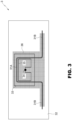
- Figures 2 and 3 schematically illustrate two further non-limiting examples of patch RFID devices based on the teachings of the present invention.
- Figures 2 and 3 show top views of respectively:
- the second antenna of the fourth patch RFID device 3 includes:
- the second antenna (respectively formed by a straight parasitic radiator or by an assembly of twisted conductive and non-conductive wires) might conveniently extend completely on the first insulating layer that, in this case, would have larger planar size (additionally, the second antenna being completely covered by the second insulating layer having larger planar size too).
- first and second insulating layers with larger planar size and with the second antenna completely sandwiched therebetween allows protecting more effectively the second antenna, even if this advantage might be paid in terms of slightly less flexibility of the multilayer planar structure.
- the use of smaller planar size for the first and second insulating layers, whereby the second antenna is sandwiched partially between said first and second insulating layers and partially between the substrate and the top rubber layer / tire's inner liner allows increasing flexibility of the multilayer planar structure (unfortunately, this might be paid in terms of more fragility of the second antenna at the edge between the sandwich formed by the first and second insulating layers and the sandwich formed by the substrate and the top rubber layer / tire's inner liner).
- the present invention provides, in general, a patch RFID device for tires with enhanced performance and features with respect to those of currently known solutions and, in particular, such that to avoid causing damages to tires or to cords thereof.
Landscapes
- Engineering & Computer Science (AREA)
- Computer Hardware Design (AREA)
- Microelectronics & Electronic Packaging (AREA)
- Physics & Mathematics (AREA)
- General Physics & Mathematics (AREA)
- Theoretical Computer Science (AREA)
- Mechanical Engineering (AREA)
- Computer Networks & Wireless Communication (AREA)
- Details Of Aerials (AREA)
- Tires In General (AREA)
- Support Of Aerials (AREA)
- Wire Bonding (AREA)
- Discharge Heating (AREA)
- Physical Or Chemical Processes And Apparatus (AREA)
Description
- The present invention relates to an improved radiofrequency identification (RFID) device for use in tires.
- In tire sector, it is felt the need for solutions enabling automated and univocal identification of tires during manufacturing, use and disposal thereof.
- For example, with specific reference to tire manufacture, automated and univocal identification of tires may allow optimizing manufacturing processes and logistics operations, boosting the use of automated control systems, performing an efficient tire tracking/tracing and, hence, realizing smart tire factories.
- In this context, the use of barcodes applied to tires to manage tire production and production history of individual tires is known. However, this solution has its limitations since printed barcodes allow registration of a limited number of information items, need to be read one by one with a given line of sight, and run the risk of being deleted or corrupted during manufacturing and/or normal operation/use of tires, thereby becoming illegible or, anyway, difficult to read.
- In order to solve such limitations,
US 2016/0092814 A1 proposes using a tire identification system based on radiofrequency identification (RFID) tags. In particular,US 2016/0092814 A1 discloses a tire production management system using RFID tags, whose operation includes: attaching an RFID tag to a tire before producing a finished tire in tire manufacturing processes; recognizing the tire tag attached to the tire in each of manufacturing processes; and thus managing information according to a manufacturing process on an individual tire. The tire production management system according toUS 2016/0092814 A1 comprises: an RFID tag attachment part; a plurality of RFID readers; a plurality of management terminals for respective processes; a lot management server; and a tire production management server. - Moreover,
Italian patent application No. 102016000009727 - Furthermore,
WO 2018/104621 A1 discloses a method for manufacturing a rubber patch comprising a radiofrequency transponder and a tire comprising such a rubber patch, wherein said rubber patch has a first layer and a second layer, that involves molding and vulcanizing a first layer, the outer surface of which comprises a recess suitable for receiving a radiofrequency transponder, placing a transponder in said recess and then positioning and vulcanizing a second layer in order to embed the transponder between the two layers. - In this connection, it is worth noting that embedding an RFID tag (that is typically a rigid metallic body) in a tire (that is, instead, an elastic and highly flexible body) may cause damages to the tire or to cords thereof (e.g., it may cause tire layer separation/delamination, cord breakage, etc.) during manufacturing of the tire (e.g., during tire vulcanization/curing) and also during its normal operation, with consequent safety risks.
-
US2012152028 discloses a slim self-powering power supplier using a flexible PCB for a wireless sensor network and a sensor node using the same, and a fabrication method thereof. -
CN201489565 discloses a flexible UHF frequency range RFID label which comprises a substrate, an antenna and a chip, wherein the substrate is a soft synthesized resin body, and the antenna is a printed circuit and includes a first antenna and a second antenna. -
WO2016193457 discloses a radiofrequency transponder corresponding to the assembly, without electromechanical connection, of a radiating antenna and an electronic part wherein the radiating antenna is a single-strand coil spring forming a dipole antenna. -
EP1459911 discloses a method of attaching a tag to the inner surface of a tire including coating a tag or a premask film with a pressure sensitive adhesive on a side and adhering that side of the tag or premask to the inner surface of a tire. - The Applicant has carried out an in-depth study in order to develop an improved RFID device for use in tires, thereby conceiving the present invention.
- Thence, a general object of the prevent invention is that of providing an RFID device for tires with enhanced performance and features with respect to those of currently known solutions.
- Moreover, a specific object of the present invention is that of providing an RFID device such that to avoid causing damages to tires or to cords thereof.
- These and other objects are achieved by the present invention in that it relates to a patch radiofrequency identification (RFID) device for tires, as defined in the appended
independent device claim 1. - More specifically, the present invention concerns a patch RFID device for tires, designed to be applied to an inner liner of a tire before or after tire vulcanization/curing and comprising a flexible multilayer planar structure including:
- a substrate;
- a first insulating layer covering a first portion of the substrate, thereby leaving exposed a second portion thereof extending around said first portion;
- an RFID chip and a first antenna that are connected to each other and arranged on the first insulating layer;
- a second antenna that is electromagnetically coupled with the first antenna and that extends, at least partially, on the first insulating layer; wherein the RFID chip, the first antenna and the second antenna lie on one and the same plane; and
- a second insulating layer covering the first insulating layer, the RFID chip, the first antenna and, at least partially, the second antenna.
- Conveniently, the second antenna:
- either extends partially on the first insulating layer and partially on the second portion of the substrate and is partially covered by the second insulating layer;
- or extends completely on the first insulating layer and is completely covered by the second insulating layer.
- More conveniently, the second antenna includes:
- a first portion that extends on the first insulating layer and is covered by the second insulating layer; and
- a second portion that
- either extends from said first portion on the first insulating layer and is covered by the second insulating layer,
- or extends from said first portion on the second portion of the substrate and is not covered by the second insulating layer.
- Conveniently, the multilayer planar structure further includes a top rubber layer covering the second insulating layer and the second portion of the substrate (and also the second portion of the second antenna, if it extends on the second portion of the substrate), wherein said top rubber layer is designed to be applied to an inner liner of a tire.
- Alternatively, the multilayer planar structure is conveniently designed to be applied to an inner liner of a tire so that the inner liner covers the second insulating layer and the second portion of the substrate (and also the second portion of the second antenna, if it extends on the second portion of the substrate).
- Differently, the patch RFID device can conveniently comprise a patch formed by two or more layers, wherein said patch encapsulates the multilayer planar structure and is designed to be applied to an inner liner of a tire.
- Conveniently, the first antenna is designed to operate as a near-field coupler, and the second antenna is designed to operate as a far-field radiating antenna.
- Preferably, the second antenna is a parasitic radiator that can be conveniently formed by:
- a meander-line-shaped conductive wire, or
- a straight conductive wire, or
- an assembly of twisted conductive wires, or
- an assembly of twisted conductive and non-conductive wires.
- Preferably, the first antenna is a two-dimensional (2D) folded structure (e.g., having a loop-like or circular or rectangular or square or meander-line-like or spiral-like shape).
- Conveniently, the second antenna is formed by an assembly of twisted conductive wires or by an assembly of twisted conductive and non-conductive wires; wherein:
- relative positions of the first antenna and of the first portion of the second antenna are such that to achieve electromagnetic coupling between the two antennas;
- the first portion of the second antenna includes two ends located at opposite sides of the first antenna; and
- the second portion of the second antenna includes two straight arms extending in opposite directions from the first antenna, each from a respective end of the first portion of the second antenna.
- More conveniently, the second antenna is formed by an assembly of twisted conductive and non-conductive wires; wherein the multilayer planar structure further includes a reinforcement mesh attached on the RFID chip, the first antenna, the first insulating layer and, at least partially, the second portion of the substrate; and wherein the assembly of twisted conductive and non-conductive wires is interlaced with the reinforcement mesh so that said reinforcement mesh causes said assembly of twisted conductive and non-conductive wires to maintain shapes of the first portion and the second portion of the second antenna.
- Otherwise, the second antenna may be conveniently formed by a straight assembly of twisted conductive wires, or of twisted conductive and non-conductive wires.
- Conveniently, the RFID chip is configured to:
- store an univocal identifier assigned to the tire in which the patch RFID device is embedded;
- receive, via the second and the first antennas, interrogation signals from RFID readers; and
- transmit, via the first and the second antennas, backscattered interrogation signals carrying the univocal identifier.
- Preferably, the RFID chip is configured to perform a self-tuning of a respective input impedance and/or of an input impedance of the first and second antennas so as to compensate for varying surrounding dielectric/electromagnetic conditions.
- Preferably, a temperature sensor is integrated in the RFID chip to measure temperature values; wherein the RFID chip is configured to transmit, via the first and the second antennas, backscattered interrogation signals carrying the temperature values measured by the temperature sensor.
- Conveniently, the first insulating layer is attached to the substrate by means of a first adhesive material/layer, and the top rubber layer or the inner liner is attached to the second insulating layer by means of a second adhesive material/layer.
- Conveniently, a protective resin is interposed between:
- the RFID chip and the first antenna, and
- the second insulating layer.
- Conveniently, the substrate is made of rubber, or of one or more polymeric materials, or of paper, or of textile/fabric.
- For a better understanding of the present invention, preferred embodiments, which are intended purely by way of non-limiting examples, will now be described with reference to the attached drawings (all not to scale), where:
-
Figures 1A and1B schematically illustrate a first patch RFID device and a second patch RFID device according to two alternative embodiments of the present invention; -
Figure 2 schematically illustrates a third patch RFID device according to a different illustrative embodiment of the present invention; and -
Figure 3 schematically illustrates a fourth patch RFID device according to a yet different illustrative embodiment of the present invention. - The following discussion is presented to enable a person skilled in the art to make and use the invention. Various modifications to the embodiments shown and described will be readily apparent to those skilled in the art, without departing from the scope of the present invention as claimed. Thence, the present invention is not intended to be limited to the embodiments shown and described, but is to be accorded the widest scope of protection consistent with the principles and features disclosed herein and defined in the appended claims.
- The present invention concerns a patch radiofrequency identification (RFID) device for tires, comprising a flexible multilayer planar structure that includes:
- a (planar and flexible) substrate made of a given material (preferably rubber, e.g. of inner liner type; however, even other materials could be conveniently used, such as a polymeric material, paper, textile/fabric, etc.);
- a first (planar and flexible) insulating layer covering a first portion of the substrate, thereby leaving exposed a second portion of the substrate, which second portion extends around the first portion of said substrate;
- an RFID chip and a first (flexible) antenna that are connected to each other and arranged on the first insulating layer;
- a second (flexible) antenna that is electromagnetically coupled (preferably, inductively coupled) with the first antenna and that extends, at least partially, on the first insulating layer (wherein the first antenna is conveniently designed to operate as a near-field coupler, and the second antenna is conveniently designed to operate as a far-field radiating antenna); and
- a second (planar and flexible) insulating layer covering the first insulating layer, the RFID chip, the first antenna and, at least partially, the second antenna.
- In particular, the RFID chip, the first antenna and the second antenna substantially lie on one and the same plane.
- Conveniently, the second antenna:
- either extends partially on the first insulating layer and partially on the second portion of the substrate and is partially covered by the second insulating layer;
- or extends completely on the first insulating layer and is completely covered by the second insulating layer.
- More conveniently, the second antenna includes:
- a first portion that extends on the first insulating layer and is covered by the second insulating layer; and
- a second portion that
- either extends from said first portion on the first insulating layer and is covered by the second insulating layer,
- or extends from said first portion on the second portion of the substrate and is not covered by the second insulating layer.
- Preferably, the multilayer planar structure further includes a top (planar and flexible) rubber layer covering the second insulating layer and the second portion of the substrate (and also the second portion of the second antenna, if it extends on the second portion of the substrate), wherein said top rubber layer is designed to be applied to an inner liner of a tire.
- Alternatively, the multilayer planar structure does not include the top rubber layer and is conveniently designed to be applied to an inner liner of a tire so that the inner liner covers the second insulating layer and the second portion of the substrate (and also the second portion of the second antenna, if it extends on the second portion of the substrate), thereby acting as said top rubber layer.
- Differently, the patch RFID device can conveniently comprise a patch formed by two or more layers, wherein said patch encapsulates the multilayer planar structure and is designed to be applied to an inner liner of a tire. In this case, the multilayer planar structure can conveniently include also one or more additional layers, such as one or more additional layers:
- made of soft material(s) for absorbing mechanical stress during tire rolling, and/or
- allowing adhesion to rubber, and/or
- allowing trapped air to escape while preventing rubber flow, and/or
- having electromagnetic properties such that to optimize RFID communication performance (e.g., in terms of impedance matching and losses).
- As just explained, the patch RFID device according to the present invention is designed to be applied to the inner liner of a tire, preferably before tire vulcanization/curing (however, it is worth noting that the patch RFID device could be conveniently applied to the inner liner of a tire also after tire vulcanization/curing). The flexible multilayer planar structure provides a highly strong integral adhesion of the patch RFID device to the inner liner, also during normal operation/use of the tire.
- In this connection, it is worth noting that, as previously explained, traditional rigid RFID tags, when embedded in tires, may cause damages to the tires or to cords thereof during tire manufacturing (e.g., during tire vulcanization/curing) and also during tire normal operation, with related safety risks. Instead, the flexible multilayer planar structure of the patch RFID device according to the present invention is such that to avoid any damage to the tire and to the cords thereof (in particular, thanks to its extremely reduced gauge/thickness and its flexibility).
- Moreover, since the RFID chip, the first antenna and (at least) the first portion of the second antenna are fixedly/integrally attached/formed on the first insulating layer, mutual positions of the first antenna and of the first portion of the second antenna are maintained fixed (i.e., coupling geometry between said first antenna and said first portion of the second antenna is maintained fixed) during tire vulcanization/curing and, then, during normal operation/use of the tire, thereby preventing degradation of RFID communication performance due to mutual displacement of the two antennas.
- Additionally, the use of a rubber substrate and, if present, also of the top rubber layer in the flexible multilayer planar structure allows, after tire vulcanization/curing, to firmly attach the patch RFID device to the inner liner, wherein the RFID chip and the first and second antennas are encapsulated in the two rubber layers (i.e., the rubber substrate and the top rubber layer) without air inside.
- Moreover, the use of a rubber substrate in the patch RFID device matches current tire manufacturing process/machinery and allows increasing tire assembly production efficiency (above all, when the inner liner acts as the top rubber layer).
- Conveniently, the first insulating layer is attached to the substrate by means of a first adhesive material/layer, and the top rubber layer or the inner liner is attached to the second insulating layer by means of a second adhesive material/layer.
- Preferably, in order to further strengthen adhesion, a protective resin is interposed between:
- the RFID chip and the first antenna (and, conveniently, also (at least) the first portion of the second antenna), and
- the second insulating layer.
- Conveniently, the first and second insulating layers are made of an insulating material, such as a plastic polymer (e.g., polyethylene terephthalate (PET), polyethylene (PE), polyvinyl chloride (PVC), biaxially-oriented polyethylene terephthalate (BoPET - e.g., mylar), Kapton, etc.); however, even other insulating materials could be conveniently used, such as paper and natural or synthetic fibers.
- Preferably, the second antenna is a parasitic radiator.
- According to a first preferred embodiment of the present invention, the second antenna can conveniently be a meander line antenna (MLA) formed by a meander-line-shaped conductive wire, such as a meander-line-shaped metal or metalized wire (e.g., made of copper, steel, silver, aluminum, etc. - said meander-line-shaped metal/metalized wire could be also conveniently enameled with an insulating polymeric material, such as polyurethane). This allows making a patch RFID device with low gauge/thickness, thereby facilitating tire assembling, avoiding trapped air and reducing scraps, whereas tire durability is not affected by the low gauge/thickness of the patch RFID device. This first preferred embodiment provides long reading distances. Moreover, it is worth noting that, by increasing second antenna's diameter (however, always maintaining its wire antenna configuration), it is possible to increase also fatigue resistance of the second antenna mainly in plane (e.g., with respect to traction in tire building/curing step).
- Instead, according to a second preferred embodiment of the present invention, the second antenna can be conveniently formed by:
- a) a straight conductive wire, such as a straight metal or metalized wire (e.g., made of copper, steel, silver, aluminum, etc.) - said straight metal/metalized wire could be also conveniently enameled with an insulating polymeric material, such as polyurethane; or
- b) an assembly of twisted conductive wires, such as an assembly of twisted metal or metalized wires (optionally, enameled with an insulating polymeric material, such as polyurethane); or
- c) an assembly of twisted conductive and non-conductive wires, such as an assembly of twisted fabric and metal/metalized wires (optionally, enameled with an insulating polymeric material, such as polyurethane).
- With specific reference to the above options b) and c), the second antenna may conveniently include:
- b1) a straight assembly of twisted conductive wires, or
- c1) a straight assembly of twisted conductive and non-conductive wires;
or otherwise:- b2) an assembly of twisted conductive wires forming
- the first portion of the second antenna that partially surrounds the first antenna (e.g., by forming a U-shape) to achieve electromagnetic (preferably, inductive) coupling therewith, and that has two ends located at opposite sides of the first antenna, and
- the second portion of the second antenna including two straight arms extending in opposite directions from the first antenna, each from a respective end of the first portion of said second antenna; or
- c2) an assembly of twisted conductive and non-conductive wires forming
- the first portion of the second antenna that partially surrounds the first antenna (e.g., by forming a U-shape) to achieve electromagnetic (preferably, inductive) coupling therewith, and that has two ends located at opposite sides of the first antenna, and
- the second portion of the second antenna including two straight arms extending in opposite directions from the first antenna, each from a respective end of the first portion of said second antenna.
- b2) an assembly of twisted conductive wires forming
- In particular, if the option c1) or c2) is adopted for the second antenna, a reinforcement mesh (such as a fabric mesh) is conveniently used to cause the assembly of twisted conductive and non-conductive wires to have the aforesaid shapes (i.e., the straight shape of option c1), or the U-shape plus the two straight arms of option c2)). More in detail, the reinforcement mesh is conveniently attached on the RFID chip, the first antenna, the first insulating layer and, at least partially, the second portion of the substrate, and the assembly of twisted conductive and non-conductive wires forming the second antenna is conveniently interlaced with the reinforcement mesh so that said reinforcement mesh causes said assembly of twisted conductive and non-conductive wires to:
- c1) have a straight shape; or
- c2) form
- a first portion partially surrounding the first antenna and having two ends located at opposite sides of the first antenna, and
- a second portion including two straight arms extending in opposite directions from the first antenna, each from a respective end of said first portion.
- The second preferred embodiment of the present invention allows increasing fatigue resistance of the second antenna in all direction even with small diameter of the second antenna (this is particular advantageous in tire building/curing step). Moreover, this second preferred embodiment allows increasing also assembly fatigue resistance during normal operation/use of the tires.
- More in general, the use of the second preferred embodiment of the present invention allows:
- avoiding weaker points at low radius curvatures with respect to the MLA according to the first embodiment, thereby increasing fatigue resistance of the second antenna (both during tire building/curing step and normal operation/use of the tires);
- increasing RFID tag productivity (i.e., faster production); and
- obtaining a more stable geometry and, hence, a more stable performance as for reading distance.
- Preferably, the first antenna is a two-dimensional (2D) folded structure.
- In view of the foregoing, it is immediately clear to those skilled in the art that different shapes can be advantageously exploited for the first antenna (e.g., loop-like, circular, rectangular, square, meander-line-like, spiral-like, etc.) and the second antenna (which could even cross the first antenna), provided that relative positions of the two antennas (in particular, of the first antenna and of the first portion of the second antenna) allows achieving mutual electromagnetic coupling.
- Conveniently, the first antenna is made by applying etching technology on the first insulating layer and is connected to the RFID chip through flip-chip bonding.
- Conveniently, the RFID chip is configured to:
- store an univocal identifier assigned to the tire in which the patch RFID device is embedded (and, conveniently, also additional data related to said tire - e.g., information items indicating tire model, date and/or place of production, tire materials, etc.);
- receive, via the second and the first antennas, interrogation signals from RFID readers; and
- transmit, via the first and the second antennas, backscattered interrogation signals carrying the univocal identifier (and, conveniently, also the additional data).
- Preferably, the RFID chip is configured to perform a self-tuning of its input impedance and/or of the input impedance of the first and second antennas so as to compensate for varying surrounding dielectric/electromagnetic conditions. In this way, the patch RFID device is able to adapt itself to the surrounding dielectric/electromagnetic conditions (for example, it is able to adapt itself to the specific tire which it is embedded in), thereby maximizing its RFID communication performance (e.g., in terms of reading distance). Thanks to the self-tuning capability of the RFID chip, it is possible to design and make a single model of patch RFID device capable of adapting itself to different types of tires. In other words, the self-tuning capability of the RFID chip allows avoiding designing and making antennas with different shapes and lengths depending on different models/types of tires.
- Moreover, the RFID chip preferably includes a temperature sensor integrated therein. In this way, in use, when subject to reading by an RFID reader, the patch RFID device is able to provide, in addition to the univocal identifier of the tire in which it is embedded, also temperature values measured by the temperature sensor integrated in the RFID chip.
- As for dimensions of the patch RFID device, it may be noted that:
- the substrate may conveniently have a thickness comprised between 0.1 and 1.0 mm, preferably between 0.4 and 0.6 mm;
- the first and second insulating layers may conveniently have, each, a thickness comprised between 0.001 and 0.01 mm, preferably between 0.002 mm and 0.005 mm;
- the optional top rubber layer may conveniently have a thickness comprised between 0.1 and 1 mm, preferably between 0.5 and 1 mm.
- Conveniently, the first and second insulating layers may be fitted with one or more holes to let rubber pass through said first and second insulating layers (from the rubber substrate toward the optional top rubber layer or the inner liner of the tire, and vice versa), thereby rendering the patch RFID device more stable.
- For a better understanding of the present invention,
Figures 1A and1B schematically illustrate two patch RFID devices according to two alternative embodiments of the present invention. In particular,Figures 1A and1B show top views of respectively: - a first patch RFID device (in
Figure 1A denoted as a whole by 1A) fitted with a first MLA (inFigure 1A denoted by 11A) as second antenna, wherein saidfirst MLA 11A extends partially on the first insulating layer (inFigure 1A denoted by 13A) and partially on the substrate (inFigure 1A denoted by 12A); and - a second patch RFID device (in
Figure 1B denoted as a whole by 1B) fitted with a second MLA (inFigure 1B denoted by 11B) as second antenna, wherein saidsecond MLA 11B extends completely on the first insulating layer (inFigure 1A denoted by 13B). - In this connection, it is important to note that, for the sake of illustration clarity, no second insulating layer and no top rubber layer are shown in
Figures 1A and1B so as to provide a clear view of the substrate (denoted by 12A inFigure 1A and by 12B inFigure 1B ), the first insulatinglayer Figures 1A and1B denoted by, respectively, 14A and 14B) and the first antenna (inFigures 1A and1B denoted by, respectively, 15A and 15B). - Moreover,
Figures 2 and3 schematically illustrate two further non-limiting examples of patch RFID devices based on the teachings of the present invention. In particular,Figures 2 and3 show top views of respectively: - a third patch RFID device (in
Figure 2 denoted as a whole by 2) fitted with a straight parasitic radiator (inFigure 2 denoted by 21) as second antenna; and - a fourth patch RFID device (in
Figure 3 denoted as a whole by 3) fitted with a second antenna formed by an assembly of twisted conductive and non-conductive wires. - Also in connection with
Figures 2 and3 , it is important to note that, for the sake of illustration clarity, no second insulating layer and no top rubber layer are shown so as to provide a clear view of the substrate (inFigures 2 and3 denoted by, respectively, 22 and 32), the first insulating layer (inFigures 2 and3 denoted by, respectively, 23 and 33), the RFID chip (inFigures 2 and3 denoted by, respectively, 24 and 34) and the first antenna (inFigures 2 and3 denoted by, respectively, 25 and 35). - With specific reference to
Figure 3 , the second antenna of the fourthpatch RFID device 3 includes: - a
U-shaped portion 31A that partially surrounds thefirst antenna 35 to achieve electromagnetic (preferably, inductive) coupling therewith, and that has two ends located at opposite sides of thefirst antenna 35; and - two
straight arms 31B that extend in opposite directions from thefirst antenna 35, each from a respective end of theU-shaped portion 31A;
wherein theU-shaped portion 31A and the twostraight arms 31B are made by one and the same assembly of twisted conductive and non-conductive wires, which assembly of twisted conductive and non-conductive wires is interlaced with areinforcement mesh 36 so that saidreinforcement mesh 36 causes:- the
U-shaped portion 31A to have and maintain its U-shape; and - the two
straight arms 31B to have and maintain their straight shape.
- the
- It is important to note that, according to alternative versions of the third and fourth
patch RFID devices - More in general, the use of a second antenna completely or partially sandwiched between the first and the second insulating layers (with corresponding larger or smaller planar size thereof) has pros and cons. Namely, the use of first and second insulating layers with larger planar size and with the second antenna completely sandwiched therebetween allows protecting more effectively the second antenna, even if this advantage might be paid in terms of slightly less flexibility of the multilayer planar structure. On the other hand, the use of smaller planar size for the first and second insulating layers, whereby the second antenna is sandwiched partially between said first and second insulating layers and partially between the substrate and the top rubber layer / tire's inner liner, allows increasing flexibility of the multilayer planar structure (unfortunately, this might be paid in terms of more fragility of the second antenna at the edge between the sandwich formed by the first and second insulating layers and the sandwich formed by the substrate and the top rubber layer / tire's inner liner).
- From the foregoing, the technical advantages and the innovative features of the present invention are immediately clear to those skilled in the art.
- In particular, it is important to point out that the present invention provides, in general, a patch RFID device for tires with enhanced performance and features with respect to those of currently known solutions and, in particular, such that to avoid causing damages to tires or to cords thereof.
- Furthermore, many additional technical advantages of the present invention, and also of specific optional features thereof, have been previously explained in detail.
Claims (20)
- Patch radiofrequency identification device (1A, 1B, 2, 3) for tires, designed to be applied to an inner liner of a tire before or after tire vulcanization/curing and comprising a flexible multilayer planar structure including:• a substrate (12A,12B,22,32);• a first insulating layer (13A,13B,23,33) covering a first portion of the substrate (12A,12B,22,32), thereby leaving exposed a second portion thereof extending around said first portion;• a radiofrequency identification chip (14A,14B,24,34) and a first antenna (15A,15B,25,35) that are connected to each other and arranged on the first insulating layer (13A,13B,23,33);• a second antenna (11A,11B,21,31A-31B) that is electromagnetically coupled with the first antenna (15A,15B,25,35) and that extends, at least partially, on the first insulating layer (13A,13B,23,33); wherein the radiofrequency identification chip (14A,14B,24,34), the first antenna (15A,15B,25,35) and the second antenna (11A,11B,21,31A-31B) lie on one and the same plane; and• a second insulating layer covering the first insulating layer (13A,13B,23,33), the radiofrequency identification chip (14A,14B,24,34), the first antenna (15A,15B,25,35) and, at least partially, the second antenna (11A,11B,21,31A-31B);characterized in that the second antenna (11A,11B,21,31A-31B) is a parasitic radiator.
- The patch radiofrequency identification device of claim 1, wherein the second antenna (11A,11B,21,31A-31B):• extends partially on the first insulating layer (13A,23,33) and partially on the second portion of the substrate (12A,22,32) and is partially covered by the second insulating layer; or• extends completely on the first insulating layer (13B,23,33) and is completely covered by the second insulating layer.
- The patch radiofrequency identification device of claim 2, wherein the second antenna (11A,11B,21,31A-31B) includes:• a first portion (31A) that extends on the first insulating layer (13A,13B,23,33) and is covered by the second insulating layer; and• a second portion (31B) that- extends from said first portion (31A) on the first insulating layer (13B,23,33) and is covered by the second insulating layer, or- extends from said first portion (31A) on the second portion of the substrate (12A,22,32) and is not covered by the second insulating layer.
- The patch radiofrequency identification device according to any claim 1-3, wherein the multilayer planar structure further includes a top rubber layer covering the second insulating layer and the second portion of the substrate (12A,12B,22,32), wherein said top rubber layer is designed to be applied to an inner liner of a tire.
- The patch radiofrequency identification device according to any claim 1-3, wherein the multilayer planar structure is designed to be applied to an inner liner of a tire so that the inner liner covers the second insulating layer and the second portion of the substrate (12A,12B,22,32).
- The patch radiofrequency identification device according to any claim 1-3, further comprising a patch formed by two or more layers, wherein said patch encapsulates the multilayer planar structure and is designed to be applied to an inner liner of a tire.
- The patch radiofrequency identification device according to any preceding claim, wherein the first antenna (15A,15B,25,35) is designed to operate as a near-field coupler, and the second antenna (11A,11B,21,31A-31B) is designed to operate as a far-field radiating antenna.
- The patch radiofrequency identification device according to any preceding claim, wherein the second antenna is a meander line antenna (11A,11B) formed by a meander-line-shaped conductive wire.
- The patch radiofrequency identification device according to any claim 1-7, wherein the second antenna (21,31A-31B) is formed by:• a straight conductive wire, or• an assembly of twisted conductive wires, or• an assembly of twisted conductive and non-conductive wires.
- The patch radiofrequency identification device according to any preceding claim, wherein the first antenna (15A,15B,25,35) is a two-dimensional folded structure.
- The patch radiofrequency identification device of claim 3, wherein the first antenna (35) is a two-dimensional folded structure and the second antenna (31A-31B) is formed by an assembly of twisted conductive wires or by an assembly of twisted conductive and non-conductive wires; and wherein:• relative positions of the first antenna (35) and of the first portion (31A) of the second antenna are such that to achieve electromagnetic coupling between the two antennas;• the first portion (31A) of the second antenna includes two ends located at opposite sides of the first antenna (35); and• the second portion (31B) of the second antenna includes two straight arms extending in opposite directions from the first antenna (35), each from a respective end of the first portion (31A) of the second antenna.
- The patch radiofrequency identification device of claim 11, wherein the second antenna (31A-31B) is formed by an assembly of twisted conductive and non-conductive wires;wherein the multilayer planar structure further includes a reinforcement mesh (36) attached on the radiofrequency identification chip (34), the first antenna (35), the first insulating layer (33) and, at least partially, the second portion of the substrate (32);and wherein the assembly of twisted conductive and non-conductive wires is interlaced with the reinforcement mesh (36) so that said reinforcement mesh (36) causes said assembly of twisted conductive and non-conductive wires to maintain shapes of the first portion (31A) and the second portion (31B) of the second antenna.
- The patch radiofrequency identification device according to claim 9 or 10, wherein the second antenna (21) is formed by a straight assembly of twisted conductive wires, or of twisted conductive and non-conductive wires.
- The patch radiofrequency identification device according to any preceding claim, wherein the radiofrequency identification chip (14A,14B,24,34) is configured to:• store an univocal identifier assigned to the tire in which the patch radiofrequency identification device (1A,1B,2,3) is embedded;• receive, via the second (11A,11B,21,31A-31B) and the first (15A,15B,25,35) antennas, interrogation signals from radiofrequency identification readers; and• transmit, via the first (15A,15B,25,35) and the second (11A,11B,21,31A-31B) antennas, backscattered interrogation signals carrying the univocal identifier.
- The patch radiofrequency identification device according to any preceding claim, wherein the radiofrequency identification chip (14A,14B,24,34) is configured to perform a self-tuning of a respective input impedance and/or of an input impedance of the first (15A,15B,25,35) and second (11A,11B,21,31A-31B) antennas so as to compensate for varying surrounding dielectric/electromagnetic conditions.
- The patch radiofrequency identification device according to any preceding claim, wherein a temperature sensor is integrated in the radiofrequency identification chip (14A,14B,24,34) to measure temperature values; and wherein the radiofrequency identification chip (14A,14B,24,34) is configured to transmit, via the first (15A,15B,25,35) and the second (11A,11B,21,31A-31B) antennas, backscattered interrogation signals carrying the temperature values measured by the temperature sensor.
- The patch radiofrequency identification device according to claim 4 or 5, wherein the first insulating layer (13A,13B,23,33) is attached to the substrate (12A,12B,22,32) by means of a first adhesive material/layer, and the top rubber layer or the inner liner is attached to the second insulating layer by means of a second adhesive material/layer.
- The patch radiofrequency identification device according to any preceding claim, wherein a protective resin is interposed between:• the radiofrequency identification chip (14A,14B,24,34) and the first antenna (15A,15B,25,35), and• the second insulating layer.
- The patch radiofrequency identification device according to any preceding claim, wherein the substrate (12A,12B,22,32) is made of rubber, or of one or more polymeric materials, or of paper, or of textile/fabric.
- Tire fitted with the patch radiofrequency identification device as claimed in any preceding claim.
Applications Claiming Priority (2)
| Application Number | Priority Date | Filing Date | Title |
|---|---|---|---|
| IT102019000002337A IT201900002337A1 (en) | 2019-02-18 | 2019-02-18 | PERFECTED RFID DEVICE FOR TIRES |
| PCT/IB2020/050829 WO2020170057A1 (en) | 2019-02-18 | 2020-02-03 | Improved rfid device for tires |
Publications (2)
| Publication Number | Publication Date |
|---|---|
| EP3927562A1 EP3927562A1 (en) | 2021-12-29 |
| EP3927562B1 true EP3927562B1 (en) | 2024-03-27 |
Family
ID=66476756
Family Applications (1)
| Application Number | Title | Priority Date | Filing Date |
|---|---|---|---|
| EP20703301.0A Active EP3927562B1 (en) | 2019-02-18 | 2020-02-03 | Improved rfid device for tires |
Country Status (6)
| Country | Link |
|---|---|
| US (2) | US12106170B2 (en) |
| EP (1) | EP3927562B1 (en) |
| JP (1) | JP7317132B2 (en) |
| CN (1) | CN113439033A (en) |
| IT (1) | IT201900002337A1 (en) |
| WO (1) | WO2020170057A1 (en) |
Families Citing this family (24)
| Publication number | Priority date | Publication date | Assignee | Title |
|---|---|---|---|---|
| US20220355625A1 (en) * | 2019-08-22 | 2022-11-10 | FineLine Technologies | Chemically treated, rfid equipped mesh tire labels and methods of making and using the same for identification and tracking purposes during and post-tire manufacture |
| JP7457519B2 (en) * | 2020-02-18 | 2024-03-28 | 株式会社ブリヂストン | aircraft tires |
| IT202000012595A1 (en) | 2020-05-27 | 2021-11-27 | Bridgestone Europe Nv Sa | IMPROVED RFID SENSOR DEVICE WITH PATCH TYPE ANTENNA FOR TIRES |
| US11962337B2 (en) | 2021-11-03 | 2024-04-16 | Nucurrent, Inc. | Communications demodulation in wireless power transmission system having an internal repeater |
| US20230145030A1 (en) * | 2021-11-03 | 2023-05-11 | Nucurrent, Inc. | Wireless Power Transmitter with Metal Mesh for Resiliency |
| US11848566B2 (en) | 2021-11-03 | 2023-12-19 | Nucurrent, Inc. | Dual communications demodulation of a wireless power transmission system having an internal repeater |
| US11831177B2 (en) | 2021-11-03 | 2023-11-28 | Nucurrent, Inc. | Wireless power transmitter with internal repeater and enhanced uniformity |
| US11824373B2 (en) | 2021-11-03 | 2023-11-21 | Nucurrent, Inc. | Wireless power transmission antenna with parallel coil molecule configuration |
| US11824371B2 (en) | 2021-11-03 | 2023-11-21 | Nucurrent, Inc. | Wireless power transmission antenna with internal repeater and repeater filter |
| US11831173B2 (en) | 2021-11-03 | 2023-11-28 | Nucurrent, Inc. | Wireless power transmission antenna with series coil molecule configuration |
| US11862991B2 (en) | 2021-11-03 | 2024-01-02 | Nucurrent, Inc. | Wireless power transmission antenna with internal repeater and in-coil tuning |
| US11831175B2 (en) | 2021-11-03 | 2023-11-28 | Nucurrent, Inc. | Wireless power transmission antenna with antenna molecules |
| US12027880B2 (en) | 2021-11-03 | 2024-07-02 | Nucurrent, Inc. | Wireless power transfer from mouse pad to mouse |
| US11831176B2 (en) | 2021-11-03 | 2023-11-28 | Nucurrent, Inc. | Wireless power transfer systems with substantial uniformity over a large area |
| US11862984B2 (en) | 2021-11-03 | 2024-01-02 | Nucurrent, Inc. | Wireless power receiver with repeater for enhanced power harvesting |
| US11824372B2 (en) | 2021-11-03 | 2023-11-21 | Nucurrent, Inc. | Wireless power transmission antenna with puzzled antenna molecules |
| IT202100032225A1 (en) * | 2021-12-22 | 2023-06-22 | Bridgestone Europe Nv Sa | METHOD OF PRODUCTION OF A TIRE EQUIPPED WITH AN ELECTRONIC DEVICE |
| KR20250051655A (en) * | 2022-07-07 | 2025-04-17 | 코드사 테크닉 테크스틸 아노님 시르케티 | Contactless activated RFID tags for tires |
| US12431632B2 (en) * | 2023-03-03 | 2025-09-30 | Meta Platforms Technologies, Llc | Systems and methods for integrating antennas into textile bands |
| KR102636494B1 (en) * | 2023-06-28 | 2024-02-14 | 주식회사 윌켐코리아 | RFID tag for tire burial with improved transmission and reception sensitivity |
| JPWO2025027996A1 (en) * | 2023-07-28 | 2025-02-06 | ||
| KR102734497B1 (en) * | 2024-02-07 | 2024-11-26 | 주식회사 윌켐코리아 | Manufacturing method of a wireless recognition tag for tire attachment that suppresses air bubbles and improves durability |
| KR102835030B1 (en) * | 2024-06-11 | 2025-07-16 | 주식회사 윌켐코리아 | Wireless recognition tag for tire installation and its manufacturing method |
| KR102756019B1 (en) * | 2024-07-24 | 2025-01-21 | 주식회사 윌켐코리아 | Wireless recognition tag for tire attachment and its manufacturing method |
Family Cites Families (27)
| Publication number | Priority date | Publication date | Assignee | Title |
|---|---|---|---|---|
| US5479171A (en) * | 1993-04-27 | 1995-12-26 | Texas Instruments Deutschland Gmbh | Extended range RF-ID transponder |
| JPH0730104U (en) * | 1993-11-12 | 1995-06-06 | 株式会社ブリヂストン | Pneumatic tire with built-in transponder |
| US20040159383A1 (en) * | 2002-06-11 | 2004-08-19 | Adamson John David | Method for embedding a radio frequency antenna in a tire, and an antenna for embedding in a tire |
| US6854324B2 (en) * | 2002-12-20 | 2005-02-15 | The Goodyear Tire & Rubber Company | Tire monitoring apparatus |
| US7091841B2 (en) * | 2003-02-19 | 2006-08-15 | Michelin Recherche Et Technique, S.A. | Tire electronics assembly having a multi-frequency antenna |
| US20040182494A1 (en) * | 2003-03-19 | 2004-09-23 | Dominak Stephen L. | Tag attachment for tires and method of attaching tags to tires |
| KR100630823B1 (en) * | 2004-11-02 | 2006-10-02 | 주식회사 현대오토넷 | Radio wave identification tag device for tire in radio wave identification system |
| WO2006120250A2 (en) * | 2005-05-13 | 2006-11-16 | Fractus, S.A. | Antenna diversity system and slot antenna component |
| US7825868B2 (en) * | 2007-06-15 | 2010-11-02 | Emag Technologies, Inc. | Hand held reader antenna for RFID and tire pressure monitoring system |
| FR2937284B1 (en) * | 2008-10-20 | 2010-11-19 | Michelin Soc Tech | INSTRUMENT PNEUMATIC AND PNEUMATIC BODY |
| US20100122757A1 (en) | 2008-11-18 | 2010-05-20 | Robert Edward Lionetti | Tire and electronic device assembly |
| JP5510450B2 (en) | 2009-04-14 | 2014-06-04 | 株式会社村田製作所 | Wireless IC device |
| CN201489565U (en) * | 2009-09-01 | 2010-05-26 | 上海韩硕信息科技有限公司 | Flexible UHF frequency range RFID label |
| IT1401990B1 (en) * | 2010-09-30 | 2013-08-28 | Pirelli | METHOD AND SYSTEM TO DETERMINE POTENTIAL FRICTION BETWEEN A TIRE FOR VEHICLES AND A ROLLING SURFACE |
| KR101725115B1 (en) * | 2010-12-16 | 2017-04-26 | 한국전자통신연구원 | Power Supplier Using a Flexible PCB Based Self-powering and Sensor Node Using The Same |
| JP2012240603A (en) * | 2011-05-23 | 2012-12-10 | Yokohama Rubber Co Ltd:The | Pneumatic tire |
| KR101545385B1 (en) | 2013-05-15 | 2015-08-18 | 아시아나아이디티 주식회사 | An management system for manufacturing tires using rfid tag |
| CN103546188A (en) | 2013-10-30 | 2014-01-29 | 西安乾易企业管理咨询有限公司 | Wireless mobile terminal of self-tuning antenna and adjusting method of self-tuning antenna |
| CA2883972A1 (en) * | 2014-03-03 | 2015-09-03 | Berntsen Int, Inc. | Advanced system for navigating between, locating and monitoring underground assets |
| EP3065089B1 (en) * | 2015-03-02 | 2017-12-20 | Gemalto SA | Method for manufacturing a radiofrequency device with passive wire antenna |
| FR3037200B1 (en) * | 2015-06-03 | 2017-05-26 | Michelin & Cie | RADIOFREQUENCY TRANSPONDER FOR PNEUMATIC |
| WO2017130956A1 (en) | 2016-01-25 | 2017-08-03 | トッパン・フォームズ株式会社 | Tire with embedded rfid tag |
| TWI626790B (en) * | 2016-08-18 | 2018-06-11 | 創新聯合科技股份有限公司 | Long-distance radio frequency electronic identification tire structure |
| CN206584389U (en) | 2016-11-15 | 2017-10-24 | 刘台华 | Inductive coupling type RFID antenna device |
| US20180151949A1 (en) * | 2016-11-30 | 2018-05-31 | Trw Automotive Us Llc | Antenna with parasitic element |
| FR3059592A1 (en) | 2016-12-05 | 2018-06-08 | Compagnie Generale Des Etablissements Michelin | METHOD FOR MANUFACTURING A PATCH EQUIPPED WITH A RADIOFREQUENCY AND PNEUMATIC TRANSPONDER COMPRISING SUCH A PATCH |
| CN107116977B (en) * | 2017-05-23 | 2023-07-14 | 山东玲珑轮胎股份有限公司 | a smart tire |
-
2019
- 2019-02-18 IT IT102019000002337A patent/IT201900002337A1/en unknown
-
2020
- 2020-02-03 US US17/424,303 patent/US12106170B2/en active Active
- 2020-02-03 EP EP20703301.0A patent/EP3927562B1/en active Active
- 2020-02-03 JP JP2021548157A patent/JP7317132B2/en active Active
- 2020-02-03 WO PCT/IB2020/050829 patent/WO2020170057A1/en not_active Ceased
- 2020-02-03 CN CN202080014893.9A patent/CN113439033A/en active Pending
-
2024
- 2024-08-30 US US18/821,440 patent/US20240419935A1/en active Pending
Also Published As
| Publication number | Publication date |
|---|---|
| CN113439033A (en) | 2021-09-24 |
| IT201900002337A1 (en) | 2020-08-18 |
| EP3927562A1 (en) | 2021-12-29 |
| WO2020170057A1 (en) | 2020-08-27 |
| JP7317132B2 (en) | 2023-07-28 |
| US20240419935A1 (en) | 2024-12-19 |
| US12106170B2 (en) | 2024-10-01 |
| JP2022519907A (en) | 2022-03-25 |
| US20220134814A1 (en) | 2022-05-05 |
Similar Documents
| Publication | Publication Date | Title |
|---|---|---|
| EP3927562B1 (en) | Improved rfid device for tires | |
| KR100845474B1 (en) | LF ID tag for tire laying | |
| JP7227902B2 (en) | RFID tags designed to work on difficult substrates | |
| US7453407B2 (en) | Antenna constructions for electronic devices and methods for manufacturing such antenna constructions | |
| US11295193B2 (en) | Radiofrequency transponder for tire | |
| EP1742296B1 (en) | Antenna and RFID tag mounting the same | |
| EP2920010B1 (en) | Rfid tag with rubber, elastomer, or polymer antenna | |
| KR102589509B1 (en) | Dual-band transponder and textile label with dual-band transponder | |
| JP2019041374A (en) | RFID transponder in plastic package for non-contact communication | |
| US10878306B2 (en) | RFID transponder antenna | |
| KR20130108797A (en) | Rfid tag for tire | |
| US20170308782A1 (en) | Stretchable broad impedance bandwidth rfid devices | |
| KR20070103581A (en) | RF Antenna, RF Tag, and RF System | |
| JP7410488B2 (en) | RF tag labels and rubber products with RF tag labels | |
| JP2014067234A (en) | Rfid tag and automatic recognition system | |
| RU2796701C2 (en) | Improved tire rfid | |
| KR20220152076A (en) | UHF Band RFID Tires Tag Embedded In Tires And Their Manufacturing Methods | |
| JP7799089B2 (en) | Contactless RFID tag for tires | |
| KR100627163B1 (en) | Eyelet for RFID | |
| EP4303761B1 (en) | A contactlessly activated rfid tag for a tire | |
| KR102902721B1 (en) | Rfid tag including metal loof antenna for tire and its manufacturing method | |
| KR102899246B1 (en) | Rfid tag mounted with wire antenna for tire | |
| CN221261664U (en) | High-reliability RFID tag | |
| EP4184385B1 (en) | An information plate and a method for manufacturing the information plate | |
| JP4715823B2 (en) | RFID tag |
Legal Events
| Date | Code | Title | Description |
|---|---|---|---|
| STAA | Information on the status of an ep patent application or granted ep patent |
Free format text: STATUS: UNKNOWN |
|
| STAA | Information on the status of an ep patent application or granted ep patent |
Free format text: STATUS: THE INTERNATIONAL PUBLICATION HAS BEEN MADE |
|
| PUAI | Public reference made under article 153(3) epc to a published international application that has entered the european phase |
Free format text: ORIGINAL CODE: 0009012 |
|
| STAA | Information on the status of an ep patent application or granted ep patent |
Free format text: STATUS: REQUEST FOR EXAMINATION WAS MADE |
|
| 17P | Request for examination filed |
Effective date: 20210916 |
|
| AK | Designated contracting states |
Kind code of ref document: A1 Designated state(s): AL AT BE BG CH CY CZ DE DK EE ES FI FR GB GR HR HU IE IS IT LI LT LU LV MC MK MT NL NO PL PT RO RS SE SI SK SM TR |
|
| DAV | Request for validation of the european patent (deleted) | ||
| DAX | Request for extension of the european patent (deleted) | ||
| RAP3 | Party data changed (applicant data changed or rights of an application transferred) |
Owner name: BRIDGESTONE EUROPE NV/SA |
|
| GRAP | Despatch of communication of intention to grant a patent |
Free format text: ORIGINAL CODE: EPIDOSNIGR1 |
|
| STAA | Information on the status of an ep patent application or granted ep patent |
Free format text: STATUS: GRANT OF PATENT IS INTENDED |
|
| INTG | Intention to grant announced |
Effective date: 20230809 |
|
| GRAS | Grant fee paid |
Free format text: ORIGINAL CODE: EPIDOSNIGR3 |
|
| GRAA | (expected) grant |
Free format text: ORIGINAL CODE: 0009210 |
|
| STAA | Information on the status of an ep patent application or granted ep patent |
Free format text: STATUS: THE PATENT HAS BEEN GRANTED |
|
| AK | Designated contracting states |
Kind code of ref document: B1 Designated state(s): AL AT BE BG CH CY CZ DE DK EE ES FI FR GB GR HR HU IE IS IT LI LT LU LV MC MK MT NL NO PL PT RO RS SE SI SK SM TR |
|
| REG | Reference to a national code |
Ref country code: GB Ref legal event code: FG4D |
|
| REG | Reference to a national code |
Ref country code: CH Ref legal event code: EP |
|
| REG | Reference to a national code |
Ref country code: DE Ref legal event code: R096 Ref document number: 602020027882 Country of ref document: DE |
|
| REG | Reference to a national code |
Ref country code: IE Ref legal event code: FG4D |
|
| PG25 | Lapsed in a contracting state [announced via postgrant information from national office to epo] |
Ref country code: LT Free format text: LAPSE BECAUSE OF FAILURE TO SUBMIT A TRANSLATION OF THE DESCRIPTION OR TO PAY THE FEE WITHIN THE PRESCRIBED TIME-LIMIT Effective date: 20240327 |
|
| REG | Reference to a national code |
Ref country code: LT Ref legal event code: MG9D |
|
| PG25 | Lapsed in a contracting state [announced via postgrant information from national office to epo] |
Ref country code: GR Free format text: LAPSE BECAUSE OF FAILURE TO SUBMIT A TRANSLATION OF THE DESCRIPTION OR TO PAY THE FEE WITHIN THE PRESCRIBED TIME-LIMIT Effective date: 20240628 |
|
| PG25 | Lapsed in a contracting state [announced via postgrant information from national office to epo] |
Ref country code: HR Free format text: LAPSE BECAUSE OF FAILURE TO SUBMIT A TRANSLATION OF THE DESCRIPTION OR TO PAY THE FEE WITHIN THE PRESCRIBED TIME-LIMIT Effective date: 20240327 Ref country code: RS Free format text: LAPSE BECAUSE OF FAILURE TO SUBMIT A TRANSLATION OF THE DESCRIPTION OR TO PAY THE FEE WITHIN THE PRESCRIBED TIME-LIMIT Effective date: 20240627 |
|
| PG25 | Lapsed in a contracting state [announced via postgrant information from national office to epo] |
Ref country code: RS Free format text: LAPSE BECAUSE OF FAILURE TO SUBMIT A TRANSLATION OF THE DESCRIPTION OR TO PAY THE FEE WITHIN THE PRESCRIBED TIME-LIMIT Effective date: 20240627 Ref country code: NO Free format text: LAPSE BECAUSE OF FAILURE TO SUBMIT A TRANSLATION OF THE DESCRIPTION OR TO PAY THE FEE WITHIN THE PRESCRIBED TIME-LIMIT Effective date: 20240627 Ref country code: LT Free format text: LAPSE BECAUSE OF FAILURE TO SUBMIT A TRANSLATION OF THE DESCRIPTION OR TO PAY THE FEE WITHIN THE PRESCRIBED TIME-LIMIT Effective date: 20240327 Ref country code: HR Free format text: LAPSE BECAUSE OF FAILURE TO SUBMIT A TRANSLATION OF THE DESCRIPTION OR TO PAY THE FEE WITHIN THE PRESCRIBED TIME-LIMIT Effective date: 20240327 Ref country code: GR Free format text: LAPSE BECAUSE OF FAILURE TO SUBMIT A TRANSLATION OF THE DESCRIPTION OR TO PAY THE FEE WITHIN THE PRESCRIBED TIME-LIMIT Effective date: 20240628 Ref country code: FI Free format text: LAPSE BECAUSE OF FAILURE TO SUBMIT A TRANSLATION OF THE DESCRIPTION OR TO PAY THE FEE WITHIN THE PRESCRIBED TIME-LIMIT Effective date: 20240327 Ref country code: BG Free format text: LAPSE BECAUSE OF FAILURE TO SUBMIT A TRANSLATION OF THE DESCRIPTION OR TO PAY THE FEE WITHIN THE PRESCRIBED TIME-LIMIT Effective date: 20240327 |
|
| REG | Reference to a national code |
Ref country code: NL Ref legal event code: MP Effective date: 20240327 |
|
| PG25 | Lapsed in a contracting state [announced via postgrant information from national office to epo] |
Ref country code: SE Free format text: LAPSE BECAUSE OF FAILURE TO SUBMIT A TRANSLATION OF THE DESCRIPTION OR TO PAY THE FEE WITHIN THE PRESCRIBED TIME-LIMIT Effective date: 20240327 Ref country code: LV Free format text: LAPSE BECAUSE OF FAILURE TO SUBMIT A TRANSLATION OF THE DESCRIPTION OR TO PAY THE FEE WITHIN THE PRESCRIBED TIME-LIMIT Effective date: 20240327 |
|
| PG25 | Lapsed in a contracting state [announced via postgrant information from national office to epo] |
Ref country code: NL Free format text: LAPSE BECAUSE OF FAILURE TO SUBMIT A TRANSLATION OF THE DESCRIPTION OR TO PAY THE FEE WITHIN THE PRESCRIBED TIME-LIMIT Effective date: 20240327 |
|
| REG | Reference to a national code |
Ref country code: AT Ref legal event code: MK05 Ref document number: 1669585 Country of ref document: AT Kind code of ref document: T Effective date: 20240327 |
|
| PG25 | Lapsed in a contracting state [announced via postgrant information from national office to epo] |
Ref country code: NL Free format text: LAPSE BECAUSE OF FAILURE TO SUBMIT A TRANSLATION OF THE DESCRIPTION OR TO PAY THE FEE WITHIN THE PRESCRIBED TIME-LIMIT Effective date: 20240327 |
|
| PG25 | Lapsed in a contracting state [announced via postgrant information from national office to epo] |
Ref country code: IS Free format text: LAPSE BECAUSE OF FAILURE TO SUBMIT A TRANSLATION OF THE DESCRIPTION OR TO PAY THE FEE WITHIN THE PRESCRIBED TIME-LIMIT Effective date: 20240727 |
|
| PG25 | Lapsed in a contracting state [announced via postgrant information from national office to epo] |
Ref country code: PT Free format text: LAPSE BECAUSE OF FAILURE TO SUBMIT A TRANSLATION OF THE DESCRIPTION OR TO PAY THE FEE WITHIN THE PRESCRIBED TIME-LIMIT Effective date: 20240729 Ref country code: SM Free format text: LAPSE BECAUSE OF FAILURE TO SUBMIT A TRANSLATION OF THE DESCRIPTION OR TO PAY THE FEE WITHIN THE PRESCRIBED TIME-LIMIT Effective date: 20240327 |
|
| PG25 | Lapsed in a contracting state [announced via postgrant information from national office to epo] |
Ref country code: ES Free format text: LAPSE BECAUSE OF FAILURE TO SUBMIT A TRANSLATION OF THE DESCRIPTION OR TO PAY THE FEE WITHIN THE PRESCRIBED TIME-LIMIT Effective date: 20240327 |
|
| PG25 | Lapsed in a contracting state [announced via postgrant information from national office to epo] |
Ref country code: CZ Free format text: LAPSE BECAUSE OF FAILURE TO SUBMIT A TRANSLATION OF THE DESCRIPTION OR TO PAY THE FEE WITHIN THE PRESCRIBED TIME-LIMIT Effective date: 20240327 Ref country code: EE Free format text: LAPSE BECAUSE OF FAILURE TO SUBMIT A TRANSLATION OF THE DESCRIPTION OR TO PAY THE FEE WITHIN THE PRESCRIBED TIME-LIMIT Effective date: 20240327 |
|
| PG25 | Lapsed in a contracting state [announced via postgrant information from national office to epo] |
Ref country code: AT Free format text: LAPSE BECAUSE OF FAILURE TO SUBMIT A TRANSLATION OF THE DESCRIPTION OR TO PAY THE FEE WITHIN THE PRESCRIBED TIME-LIMIT Effective date: 20240327 |
|
| PG25 | Lapsed in a contracting state [announced via postgrant information from national office to epo] |
Ref country code: PL Free format text: LAPSE BECAUSE OF FAILURE TO SUBMIT A TRANSLATION OF THE DESCRIPTION OR TO PAY THE FEE WITHIN THE PRESCRIBED TIME-LIMIT Effective date: 20240327 |
|
| PG25 | Lapsed in a contracting state [announced via postgrant information from national office to epo] |
Ref country code: SK Free format text: LAPSE BECAUSE OF FAILURE TO SUBMIT A TRANSLATION OF THE DESCRIPTION OR TO PAY THE FEE WITHIN THE PRESCRIBED TIME-LIMIT Effective date: 20240327 |
|
| PG25 | Lapsed in a contracting state [announced via postgrant information from national office to epo] |
Ref country code: SM Free format text: LAPSE BECAUSE OF FAILURE TO SUBMIT A TRANSLATION OF THE DESCRIPTION OR TO PAY THE FEE WITHIN THE PRESCRIBED TIME-LIMIT Effective date: 20240327 Ref country code: SK Free format text: LAPSE BECAUSE OF FAILURE TO SUBMIT A TRANSLATION OF THE DESCRIPTION OR TO PAY THE FEE WITHIN THE PRESCRIBED TIME-LIMIT Effective date: 20240327 Ref country code: RO Free format text: LAPSE BECAUSE OF FAILURE TO SUBMIT A TRANSLATION OF THE DESCRIPTION OR TO PAY THE FEE WITHIN THE PRESCRIBED TIME-LIMIT Effective date: 20240327 Ref country code: PT Free format text: LAPSE BECAUSE OF FAILURE TO SUBMIT A TRANSLATION OF THE DESCRIPTION OR TO PAY THE FEE WITHIN THE PRESCRIBED TIME-LIMIT Effective date: 20240729 Ref country code: PL Free format text: LAPSE BECAUSE OF FAILURE TO SUBMIT A TRANSLATION OF THE DESCRIPTION OR TO PAY THE FEE WITHIN THE PRESCRIBED TIME-LIMIT Effective date: 20240327 Ref country code: IS Free format text: LAPSE BECAUSE OF FAILURE TO SUBMIT A TRANSLATION OF THE DESCRIPTION OR TO PAY THE FEE WITHIN THE PRESCRIBED TIME-LIMIT Effective date: 20240727 Ref country code: ES Free format text: LAPSE BECAUSE OF FAILURE TO SUBMIT A TRANSLATION OF THE DESCRIPTION OR TO PAY THE FEE WITHIN THE PRESCRIBED TIME-LIMIT Effective date: 20240327 Ref country code: EE Free format text: LAPSE BECAUSE OF FAILURE TO SUBMIT A TRANSLATION OF THE DESCRIPTION OR TO PAY THE FEE WITHIN THE PRESCRIBED TIME-LIMIT Effective date: 20240327 Ref country code: CZ Free format text: LAPSE BECAUSE OF FAILURE TO SUBMIT A TRANSLATION OF THE DESCRIPTION OR TO PAY THE FEE WITHIN THE PRESCRIBED TIME-LIMIT Effective date: 20240327 Ref country code: AT Free format text: LAPSE BECAUSE OF FAILURE TO SUBMIT A TRANSLATION OF THE DESCRIPTION OR TO PAY THE FEE WITHIN THE PRESCRIBED TIME-LIMIT Effective date: 20240327 |
|
| PG25 | Lapsed in a contracting state [announced via postgrant information from national office to epo] |
Ref country code: IT Free format text: LAPSE BECAUSE OF FAILURE TO SUBMIT A TRANSLATION OF THE DESCRIPTION OR TO PAY THE FEE WITHIN THE PRESCRIBED TIME-LIMIT Effective date: 20240327 |
|
| PG25 | Lapsed in a contracting state [announced via postgrant information from national office to epo] |
Ref country code: IT Free format text: LAPSE BECAUSE OF FAILURE TO SUBMIT A TRANSLATION OF THE DESCRIPTION OR TO PAY THE FEE WITHIN THE PRESCRIBED TIME-LIMIT Effective date: 20240327 |
|
| REG | Reference to a national code |
Ref country code: DE Ref legal event code: R097 Ref document number: 602020027882 Country of ref document: DE |
|
| PG25 | Lapsed in a contracting state [announced via postgrant information from national office to epo] |
Ref country code: DK Free format text: LAPSE BECAUSE OF FAILURE TO SUBMIT A TRANSLATION OF THE DESCRIPTION OR TO PAY THE FEE WITHIN THE PRESCRIBED TIME-LIMIT Effective date: 20240327 |
|
| PG25 | Lapsed in a contracting state [announced via postgrant information from national office to epo] |
Ref country code: DK Free format text: LAPSE BECAUSE OF FAILURE TO SUBMIT A TRANSLATION OF THE DESCRIPTION OR TO PAY THE FEE WITHIN THE PRESCRIBED TIME-LIMIT Effective date: 20240327 |
|
| PLBE | No opposition filed within time limit |
Free format text: ORIGINAL CODE: 0009261 |
|
| STAA | Information on the status of an ep patent application or granted ep patent |
Free format text: STATUS: NO OPPOSITION FILED WITHIN TIME LIMIT |
|
| 26N | No opposition filed |
Effective date: 20250103 |
|
| P01 | Opt-out of the competence of the unified patent court (upc) registered |
Free format text: CASE NUMBER: APP_8760/2025 Effective date: 20250220 |
|
| PG25 | Lapsed in a contracting state [announced via postgrant information from national office to epo] |
Ref country code: SI Free format text: LAPSE BECAUSE OF FAILURE TO SUBMIT A TRANSLATION OF THE DESCRIPTION OR TO PAY THE FEE WITHIN THE PRESCRIBED TIME-LIMIT Effective date: 20240327 |
|
| PG25 | Lapsed in a contracting state [announced via postgrant information from national office to epo] |
Ref country code: MC Free format text: LAPSE BECAUSE OF FAILURE TO SUBMIT A TRANSLATION OF THE DESCRIPTION OR TO PAY THE FEE WITHIN THE PRESCRIBED TIME-LIMIT Effective date: 20240327 |
|
| REG | Reference to a national code |
Ref country code: CH Ref legal event code: PL |
|
| PG25 | Lapsed in a contracting state [announced via postgrant information from national office to epo] |
Ref country code: LU Free format text: LAPSE BECAUSE OF NON-PAYMENT OF DUE FEES Effective date: 20250203 |
|
| PG25 | Lapsed in a contracting state [announced via postgrant information from national office to epo] |
Ref country code: CH Free format text: LAPSE BECAUSE OF NON-PAYMENT OF DUE FEES Effective date: 20250228 |
|
| GBPC | Gb: european patent ceased through non-payment of renewal fee |
Effective date: 20250203 |
|
| REG | Reference to a national code |
Ref country code: BE Ref legal event code: MM Effective date: 20250228 |
|
| PG25 | Lapsed in a contracting state [announced via postgrant information from national office to epo] |
Ref country code: GB Free format text: LAPSE BECAUSE OF NON-PAYMENT OF DUE FEES Effective date: 20250203 |
|
| PG25 | Lapsed in a contracting state [announced via postgrant information from national office to epo] |
Ref country code: BE Free format text: LAPSE BECAUSE OF NON-PAYMENT OF DUE FEES Effective date: 20250228 |
|
| PG25 | Lapsed in a contracting state [announced via postgrant information from national office to epo] |
Ref country code: IE Free format text: LAPSE BECAUSE OF NON-PAYMENT OF DUE FEES Effective date: 20250203 |
|
| PGFP | Annual fee paid to national office [announced via postgrant information from national office to epo] |
Ref country code: DE Payment date: 20260121 Year of fee payment: 7 |
|
| PGFP | Annual fee paid to national office [announced via postgrant information from national office to epo] |
Ref country code: FR Payment date: 20260121 Year of fee payment: 7 |