EP3927508B1 - Pivoting blade assembly for high-speed food slicing machine - Google Patents
Pivoting blade assembly for high-speed food slicing machine Download PDFInfo
- Publication number
- EP3927508B1 EP3927508B1 EP20758505.0A EP20758505A EP3927508B1 EP 3927508 B1 EP3927508 B1 EP 3927508B1 EP 20758505 A EP20758505 A EP 20758505A EP 3927508 B1 EP3927508 B1 EP 3927508B1
- Authority
- EP
- European Patent Office
- Prior art keywords
- food product
- slicing
- slicing assembly
- actuator
- cutting
- Prior art date
- Legal status (The legal status is an assumption and is not a legal conclusion. Google has not performed a legal analysis and makes no representation as to the accuracy of the status listed.)
- Active
Links
Images







Classifications
-
- B—PERFORMING OPERATIONS; TRANSPORTING
- B26—HAND CUTTING TOOLS; CUTTING; SEVERING
- B26D—CUTTING; DETAILS COMMON TO MACHINES FOR PERFORATING, PUNCHING, CUTTING-OUT, STAMPING-OUT OR SEVERING
- B26D1/00—Cutting through work characterised by the nature or movement of the cutting member or particular materials not otherwise provided for; Apparatus or machines therefor; Cutting members therefor
- B26D1/01—Cutting through work characterised by the nature or movement of the cutting member or particular materials not otherwise provided for; Apparatus or machines therefor; Cutting members therefor involving a cutting member which does not travel with the work
- B26D1/12—Cutting through work characterised by the nature or movement of the cutting member or particular materials not otherwise provided for; Apparatus or machines therefor; Cutting members therefor involving a cutting member which does not travel with the work having a cutting member moving about an axis
- B26D1/25—Cutting through work characterised by the nature or movement of the cutting member or particular materials not otherwise provided for; Apparatus or machines therefor; Cutting members therefor involving a cutting member which does not travel with the work having a cutting member moving about an axis with a non-circular cutting member
- B26D1/26—Cutting through work characterised by the nature or movement of the cutting member or particular materials not otherwise provided for; Apparatus or machines therefor; Cutting members therefor involving a cutting member which does not travel with the work having a cutting member moving about an axis with a non-circular cutting member moving about an axis substantially perpendicular to the line of cut
- B26D1/28—Cutting through work characterised by the nature or movement of the cutting member or particular materials not otherwise provided for; Apparatus or machines therefor; Cutting members therefor involving a cutting member which does not travel with the work having a cutting member moving about an axis with a non-circular cutting member moving about an axis substantially perpendicular to the line of cut and rotating continuously in one direction during cutting
-
- B—PERFORMING OPERATIONS; TRANSPORTING
- B26—HAND CUTTING TOOLS; CUTTING; SEVERING
- B26D—CUTTING; DETAILS COMMON TO MACHINES FOR PERFORATING, PUNCHING, CUTTING-OUT, STAMPING-OUT OR SEVERING
- B26D5/00—Arrangements for operating and controlling machines or devices for cutting, cutting-out, stamping-out, punching, perforating, or severing by means other than cutting
- B26D5/02—Means for moving the cutting member into its operative position for cutting
-
- B—PERFORMING OPERATIONS; TRANSPORTING
- B26—HAND CUTTING TOOLS; CUTTING; SEVERING
- B26D—CUTTING; DETAILS COMMON TO MACHINES FOR PERFORATING, PUNCHING, CUTTING-OUT, STAMPING-OUT OR SEVERING
- B26D5/00—Arrangements for operating and controlling machines or devices for cutting, cutting-out, stamping-out, punching, perforating, or severing by means other than cutting
- B26D5/08—Means for actuating the cutting member to effect the cut
-
- B—PERFORMING OPERATIONS; TRANSPORTING
- B26—HAND CUTTING TOOLS; CUTTING; SEVERING
- B26D—CUTTING; DETAILS COMMON TO MACHINES FOR PERFORATING, PUNCHING, CUTTING-OUT, STAMPING-OUT OR SEVERING
- B26D7/00—Details of apparatus for cutting, cutting-out, stamping-out, punching, perforating, or severing by means other than cutting
- B26D7/06—Arrangements for feeding or delivering work of other than sheet, web, or filamentary form
- B26D7/0625—Arrangements for feeding or delivering work of other than sheet, web, or filamentary form by endless conveyors, e.g. belts
-
- B—PERFORMING OPERATIONS; TRANSPORTING
- B26—HAND CUTTING TOOLS; CUTTING; SEVERING
- B26D—CUTTING; DETAILS COMMON TO MACHINES FOR PERFORATING, PUNCHING, CUTTING-OUT, STAMPING-OUT OR SEVERING
- B26D7/00—Details of apparatus for cutting, cutting-out, stamping-out, punching, perforating, or severing by means other than cutting
- B26D7/27—Means for performing other operations combined with cutting
- B26D7/32—Means for performing other operations combined with cutting for conveying or stacking cut product
-
- B—PERFORMING OPERATIONS; TRANSPORTING
- B26—HAND CUTTING TOOLS; CUTTING; SEVERING
- B26D—CUTTING; DETAILS COMMON TO MACHINES FOR PERFORATING, PUNCHING, CUTTING-OUT, STAMPING-OUT OR SEVERING
- B26D2210/00—Machines or methods used for cutting special materials
- B26D2210/02—Machines or methods used for cutting special materials for cutting food products, e.g. food slicers
-
- B—PERFORMING OPERATIONS; TRANSPORTING
- B26—HAND CUTTING TOOLS; CUTTING; SEVERING
- B26D—CUTTING; DETAILS COMMON TO MACHINES FOR PERFORATING, PUNCHING, CUTTING-OUT, STAMPING-OUT OR SEVERING
- B26D2210/00—Machines or methods used for cutting special materials
- B26D2210/02—Machines or methods used for cutting special materials for cutting food products, e.g. food slicers
- B26D2210/08—Idle cutting
Definitions
- This disclosure relates to systems for extending and retracting cutting mechanisms of high-speed food slicing machines.
- Food processing machines may utilize various food processing devices to process food products. For instance, some food processing machines utilize rotating cutting members to slice food products. Other food processing machines utilize varying food processing devices to form, mold, cut, package, or process food products in various ways. It can be advantageous to move the food processing devices towards or away from the food products to accomplish the desired objective.
- a rotating blade slices multiple slices of a food product or "food log.” There is usually a dwell time or period of time that the food product is not advanced toward the blade for slicing, which may occur between production of separate stacks of the food slices. This permits the produced food stack to move further along a conveyor belt before production of the next food stack begins.
- the blade continues to spin during the dwell time, but is not supposed to produce additional slices.
- the food product often is soft or has water added, it does not act as a rigid solid mass, and may bulge slightly or flow, however minutely, as it rests on the conveyor belt. Such slight bulging or flowing causes the food product to nonetheless contact the spinning blade, which produces a small quantity of food product or "shrapnel" in the form of food particles, unwanted scrap, and other small pieces of food product. This is not only unhygienic and requires additional cleaning of the machine, such accumulation of food product tends to unduly clog various mechanical linkages and mechanisms, and also represents a loss of food product and an unnecessary expense.
- Some systems have attempted to compensate for shrapnel and scrap production during the dwell time by linearly moving the blade away the food product during the dwell time. Some systems retract the food product away from the blade using a rear gripper. Other systems retract the blade away from the food product in a parallel or linear manner using rails, spindles, or other guide mechanisms. Once such system directed to linear retraction is described in a first embodiment described below with respect to Figs. 1-9 , which show that a blade assembly is moved in a linear path away from the food product. However, this requires a complex structural arrangement and is expensive to manufacture and difficult to maintain. A food slicing machine is needed to overcome one or more of the problems described above.
- DE 10 2016 003 938 A1 discloses a slicing assembly in which the blade and its motor can be moved, by means of a parallelogram between an extended and a retracted position.
- US 2011 179922 A1 discloses a slicing assembly according to the preamble of claim 1.
- FIG. 1 illustrates a perspective view of one embodiment of a food processing system 10 for processing food products, wherein this embodiment is not in accordance with the invention.
- the food processing system 10 includes a track or input conveyor 12 configured to transport the food product, a slicing apparatus or assembly 14, an auxiliary input conveyor 16, and a control system 20.
- Food product is loaded on to the track 12, which delivers it to the auxiliary input conveyor 16, which in turn, feeds the food product to the slicing apparatus 14.
- the slicing apparatus 14 includes a cutting member 15, which slices the food product. In other embodiments, the slicing apparatus 14 may vary.
- An output conveyor 18 then carries the sliced food product away from the food processing system 10.
- the control system 20 controls operation of the food processing system 10. In other embodiments, the food processing system 10 may vary.
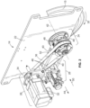
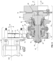
- Figure 2 illustrates a perspective view of the apparatus 14, and a mounting plate 22 to which the apparatus 14 is attached, removed from the food processing system 10 of the embodiment of Figure 1 .
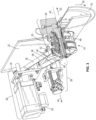
- Figure 3 illustrates the same perspective view of Figure 2 with a portion of the mounting plate 22 and a portion of a driven system 24 removed to illustrate inner components.
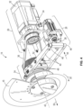
- Figure 4 illustrates an opposite side perspective view as Figure 2 with the mounting plate 22 removed.
- the apparatus 14 includes the cutting member 15, the driven system 24, a driving system 26, and an actuator system 28.
- the driving system 26 selectively rotates itself, the driven system 24, and the connected cutting member 15 in clockwise direction 30.
- the driving system 26 comprises a motor 32, a driving pulley 34, and a belt 36.
- the motor 32 selectively rotates the attached driving pulley 34, which correspondingly rotates the belt 36, which correspondingly rotates the driven system 24, which correspondingly rotates the cutting member 15 all in clockwise direction 30. In such manner, food product may be selectively sliced with the cutting member 15.
- the driving system 26 may vary.
- the actuator system 28 comprises an actuator shaft 38 (powered by a motor), and actuator arms 40.
- the actuator system 28 selectively moves the driven system 24 and the connected cutting member 15 between extended and retracted positions along axis 42.
- the actuator shaft 38 moves the cutting member 15 in the extended position
- the actuator shaft 38 moves in direction 44, thereby causing attached ends 46 of the attached actuator arms 40 to also move in direction 44.
- ends 48 of the actuator arms 40 to move in direction 50 as a result of the actuator arms 40 pivoting at pivot point 52 which is pivotally attached to the housing of the food processing system 10 shown in Figure 1 .
- the movement of the ends 48 of the actuator arms in direction 50 causes the attached driven system 24 to also move in direction 50.
- the movement of the attached driven system 24 in direction 50 causes the attached cutting member 15 to also move in direction 50.
- the cutting member 15 is disposed further away from the belt 36 than when the cutting member 15 is in the retracted position.
- the cutting member 15 is in position to slice food product.
- the movement of the ends 48 of the actuator arms in direction 44 causes the attached driven system 24 to also move in direction 44.
- the movement of the attached driven system 24 in direction 44 causes the attached cutting member 15 to also move in direction 44.
- the actuator system 28 is used to selectively cut food product by moving the cutting member 15 between the extended and retracted positions. In other embodiments, the actuator system 28 may vary.
- FIG. 5 illustrates a side view of the driving system 26, driven system 24, and cutting member 15 of the embodiment of Figure 4 with an interior of the driven system 24 being exposed.
- the driven system 24 comprises a driven pulley hub 54, a driven pulley 56, a main housing 58, a spindle housing 60, and a spindle 62.
- the driven pulley hub 54 is fixedly attached to an end 64 of the spindle 62 and to the driven pulley 56.
- the other end 66 of the spindle 62 is fixedly attached to the cutting member 15.
- the driven system 24 may vary.
- Counter weights 68 are fixedly attached to the cutting member 15.
- the motor 32 of the driving system 26 rotates the driving pulley 34 in clockwise direction 30, which correspondingly rotates the belt 36 in clockwise direction 30, the belt 36 correspondingly rotates the driven pulley 56 in clockwise direction 30.
- the driven pulley 56 is rotated in clockwise direction 30, the fixedly attached pulley hub 54 and the spindle 62 also rotate in clockwise direction 30 with the spindle 62 rotating relative to and within the spindle housing 60.
- the spindle housing 60 is fixedly attached to the main housing 58.
- the spindle 62 rotates in clockwise direction 30 relative to both the spindle housing 60 and the main housing 58.
- Rotation of the spindle 62 in clockwise direction 30 causes the fixedly attached cutting member 15 and counter weights 68 to also rotate in clockwise direction 30.
- the driving system 26 can selectively cause the cutting member 15 to rotate in clockwise direction 30 to cut food product.
- the driving pulley 34 comprises a driving pulley pocket 70 which the belt 36 is disposed against.
- a width 72 of the driving pulley pocket 70 is larger than a width 74 of the belt 36 to allow relative movement of the driving pulley 34 along axis 42A relative to the belt 36 as the actuator system 28 (discussed collectively in Figures 2-4 ) selectively moves the driven system 24 and the connected cutting member 15 between the extended and retracted positions.
- the belt 36 is allowed to traverse back and forth along axis 42A relative to the driving pulley 34 during extension and retraction of the cutting member 15 to allow the longitudinal position of the cutting member 15 to be changed without damaging the belt 36.
- the width 72 of the driving pulley pocket 70 is at least 1.3 times larger than the width 74 of the belt 36. In another embodiment, the width 72 of the driving pulley pocket 70 is at least 2 times larger than the width 74 of the belt 36. In still other embodiments, the width 72 of the driving pulley pocket 70 may vary as to how much larger it is than the width 74 of the belt 36.
- the driven pulley 56 comprises a driven pulley pocket 76 which the belt 36 is disposed against.
- a width 78 of the driven pulley pocket 76 is larger than the width 74 of the belt 36 to allow relative movement of the driven pulley 56 along axis 42 relative to the belt 36 as the actuator system 28 (discussed collectively in Figures 2-4 ) selectively moves the driven system 24 and the connected cutting member 15 between the extended and retracted positions.
- the belt 36 is allowed to walk back and forth relative to the driven pulley 56 along axis 42 during extension and retraction of the cutting member 15 to allow the longitudinal position of the cutting member 15 to be changed without damaging the belt 36.
- the width 78 of the driven pulley pocket 76 is at least 1.2 times larger than the width 74 of the belt 36 to allow relative movement between the belt 36 and the driven pulley pocket 76 to avoid damage to the belt.
- the width 78 of the driven pulley pocket 76 is at least 2 times larger than the width 74 of the belt 36. In still other embodiments, the width 78 of the driven pulley pocket 76 may vary as to how much larger it is than the width 74 of the belt 36.
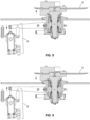
- Figure 6 illustrates a side view of the actuator system 28, driven system 24, and cutting member 15 of the embodiment of Figure 4 with an interior of the driven system 24 being exposed.
- Figure 7 illustrates a close-up view of the interior of the driven system 24 of the embodiment of Figure 6 .
- the actuator system 28 selectively moves the driven system 24 and the connected cutting member 15 between extended and retracted positions along axis 42.
- Ends 48 of the actuator arms 40 are attached to the main housing 58.
- the movement of the ends 48 of the actuator arms in direction 50 causes the attached main housing 58 to also move in direction 50. Movement of the main housing 58 in direction 50 causes the attached spindle housing 60, driven pulley hub 54, driven pulley 56, spindle 62, cutting member 15, and counter weights 68 to also move in direction 50.
- the belt 36 is allowed to walk relative to the driven pulley 56 along axis 42 during the extension of the cutting member 15 in direction 50 to allow the longitudinal position of the cutting member 15 to be changed without damaging the belt 36.
- the belt 36 is allowed to walk relative to the driving pulley 34 along axis 42A during the extension of the cutting member 15 in direction 50 to allow the longitudinal position of the cutting member 15 to be changed without damaging the belt 36.
- the cutting member 15 When the cutting member 15 is in the extended position, the cutting member 15 is disposed further away from the belt 36 than when the cutting member 15 is in the retracted position. When the cutting member 15 is in the extended position, the cutting member 15 is in position to slice food product.
- the belt 36 is allowed to walk relative to the driven pulley 56 along axis 42 during the retraction of the cutting member 15 in direction 44 to allow the longitudinal position of the cutting member 15 to be changed without damaging the belt 36.
- the belt 36 is allowed to walk relative to the driving pulley 34 along axis 42A during the retraction of the cutting member 15 in direction 44 to allow the longitudinal position of the cutting member 15 to be changed without damaging the belt 36.
- the actuator system 28 shown in Figures 6-7 is used to selectively cut food product by moving the cutting member 15 between the extended and retracted positions.
- Figure 8 illustrates the side view of the embodiment of Figure 6 with the cutting member 15 having been moved into the extended position by the actuator system 28.
- Figure 9 illustrates the side view of the embodiment of Figure 6 with the cutting member 15 having been moved into the retracted position by the actuator system 28.
- FIG 10 illustrates a second main embodiment of the food processing system 10 of Figure 1 .
- the food processing system 10 includes a pivoting blade assembly 1006 rather than the blade apparatus 14 shown in the first main embodiment of Figures 1-9 .
- the pivoting blade assembly 1006 is similar in some respects to the apparatus or blade apparatus 14 of Figures 1-9 in that it may include some similar components, such as a blade or cutting member 15, a motor 32, and a drive belt 36 operatively coupled between the motor 32 and the blade 15.
- the motor 32 is an electric servomotor, but any suitable motor may be used.
- the entire blade assembly 1006 pivots about an axis in an arcuate path between an extended position, where the blade 15 is capable of slicing the food product, and a retracted position, where the blade 15 does not contact the food product, and where a gap exists therebetween.
- the pivoting blade assembly 1006 may pivot about an axis 1008 extending between two parallel support members or extended arms 1012 of the food processing system 10.
- the blade apparatus 14 of the embodiments illustrated in Figures 1-9 does not pivot at all, but rather, moves in a linear fashion so that as the blade apparatus 14 of those figures moves between the retracted and extended position, and remains in a parallel orientation relative the food product and the cutting plane of the food product.
- blade apparatus 14 of Figures 1-9 moves linearly, along a path that is essentially coaxial with the food product, and thus the plane of the blade forms a parallel gap between the blade and the food product, which changes in width as the blade assembly 14 moves linearly between the extended and retracted positions.
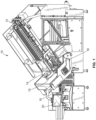
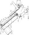
- Figure 11 shows a side view of the pivoting blade assembly 1006, which may include a blade assembly housing or support frame 1102, a motor housing 1106 configured to protect and encompass the motor 32 (which motor housing 1106 may be part of or integrally formed with the blade assembly housing 1102, or affixed thereto), and right and left side housing support rails 1110 operatively coupled to (or integrally formed with) the blade assembly housing 1102 on opposite sides thereof (only one of which is visible in the Figures).
- a motor housing 1106 configured to protect and encompass the motor 32 (which motor housing 1106 may be part of or integrally formed with the blade assembly housing 1102, or affixed thereto), and right and left side housing support rails 1110 operatively coupled to (or integrally formed with) the blade assembly housing 1102 on opposite sides thereof (only one of which is visible in the Figures).
- an actuator cylinder 1116 Also included is an actuator cylinder 1116, a cylinder piston or rod 1118 reciprocally driven by the actuator cylinder 1116, right and left side actuator linkages 1120 arranged on a driven reciprocating shaft 1122, and a support shaft 1124 about which or with the pivoting blade assembly 1006 may pivot or partially rotate during reciprocal movement between the extended position and the retracted position.
- the driven reciprocating shaft 1122 and the support shaft 1124 may be secured between the support arms 1012.
- the actuator cylinder 1116 may be secured to one of the support arms 1012 by a suitable bracket 1126, bolt, weld, or other known fastening structure.
- the support shaft 1124 may be fixed between the support arms 1012 without rotational ability, and the pivoting blade assembly 1006 may pivot about the support shaft 1124 during movement between the extended position and the retracted position. In another embodiment, the support shaft 1124 may pivot or rotate between the support arms 1012, and the pivoting blade assembly 1006 may be fixed to the support shaft 1124 during movement between the extended position and the retracted position.
- the food product 1130 is shown positioned for slicing in the food processing machine 10.
- the motor 32 is configured to drive the cutting blade 15, and in some embodiments may operatively drive the blade 15 with a belt, timing belt, pulley, or other suitable mechanical arrangement or linkage. Alternately, the motor 32 may drive the blade 15 with a gearing arrangement, such as with a worm drive, gears, and the like. Any suitable mechanism may be used to operatively couple the motor 32 to the blade 15, including a direct drive connection.
- the motor 32 of Figures 1-9 may be similar or identical to a motor housed in the motor housing 1106 of Figures 10-17 .
- Figure 12 shows a side view of the pivoting blade assembly 1006 with the blade 15 in the extended position and ready to contact the food product 1130 for slicing.
- Figure 13 shows a side view of the pivoting blade assembly 1006 with the blade 15 in the retracted position and away from the food product 1130.
- Figure 14 shows an enlarged and overly exaggerated view of the blade 15 relative to the food product 1130 in the retracted position of Figure 14 , particularly illustrating the exaggerated angle between the face of the blade 15 and the food product 1130. Note that for clarity, the angle is not drawn to scale and is greatly exaggerated for purposes of illustration only.
- the support shaft 1124 extends laterally between the parallel support arms 1012. Any suitable arrangement of the support arms 1012 may be used that have the required structural strength and rigidity to support the pivoting blade assembly 1006.
- the pivoting support shaft 1124 may be received within corresponding apertures 1140 of the left and right side housing support rails 1110, and in the embodiments that permit the blade assembly 1006 to pivot relative to a fixed support shaft 1124, a race bearing 1144 or other bearing or support pin arrangement may be included to effect smooth reciprocal rotation of the pivoting blade assembly 1106.
- the housing support rails 1110 preferably extend along a length of the blade assembly housing or frame 1102, and may be attached to the blade assembly housing 1102 using rail bolts 1148.
- any suitable means may be used to attach the housing support rails 1110 to the blade assembly housing or frame 1102, such as by welds, mechanical fasteners and the like, or in some embodiments, the housing support rails 1110 may be integrally formed with the blade assembly housing 1102.
- Figure 12 shows the pivoting blade assembly 1006 in the extended position where a plane of the cutting blade 1204 is co-planar with a cutting plane 1206 of the food product 1130.
- the cutting blade 15 may slice the food product 1130 as the food product 1130 is fed toward the cutting blade.
- the plane of the cutting blade 1204 is substantially co-planar with the cutting plane 1206 of the food product 1130.
- a small negative angle may be induced between the plane of the cutting blade 1204 and cutting plane 1206 of the food product.
- the pivoting blade assembly 1006, and hence the blade 15 may be slightly angled into the food product 1130 to compensate for blade wear.
- Such a maximum negative angle is preferably no greater than -2.30 degrees, with a typical negative angle between -0.50 degrees and -2.30 degrees if blade wear compensation is used.
- Figures 13-14 show the pivoting blade assembly 1006 in the retracted position where the plane of the cutting blade 1204 is disposed at a predetermined angle 1410 away from the cutting plane 1206 of the food product 1130. In this position, the cutting blade 15 does not contact the food product 1130.
- the predetermined angle 1410 is preferably about 5.6 degrees, but may vary between 4 degrees and 8 degrees. In some embodiments, the predetermined angle 1410 may vary between 2 degrees and 10 degrees.
- the actuator cylinder 1116 may be operatively coupled to the blade assembly housing or support frame 1102 at one end, where such operative coupling may be accomplished via left and right side linkages 1120, which preferably may be identical.
- the actuator cylinder 1116 is a linear electric servomotor.
- any suitable actuator may be used, such as a pneumatic actuator, a hydraulic actuator, a servomotor, or a stepper motor, as long as the required precise movements at rated speed can be performed.
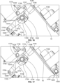
- the left and right side linkages 1120 are shown in greater detail in Figures 13-17 .
- the linkages 1120 permit the pivoting blade assembly 1006 to reciprocally move between the extended and retracted positions, as powered by the actuator cylinder 1116.
- the pivoting blade assembly 1006 is in the retracted position, which is indicated by the directional arrow "R” for "retracted” in Figure 15 when the cylinder rod 1118 is retracted into the cylinder 1116, and is in a fully backward position, as shown by arrow "B” for "backward” in Figure 15 .
- the cylinder rod 1118 terminates at a cylinder rod head 1506, which preferably attaches to the cylinder rod 1118 with a threaded connection, although any suitable connection structure may be used.
- the cylinder rod head 1506, in turn, is operatively coupled to a connecting arm 1510.
- the connecting arm 1510 which may have a first or forked end 1706 (which fork preferably has parallel portions, as best seen in Figure 15 ), may be coupled to the cylinder rod head 1506 with a fork bolt 1710.
- the connecting arm 1510 when the fork bolt 1710 is fully tightened, the connecting arm 1510 is still able to freely move or pivot about the fork bolt 1710 due to the forked configuration 1706, the spacing between forked portions, and rigidity thereof, so as to prevent frictional compression of the forked end 1706 against the cylinder rod head 1506.
- the connecting arm 1510 can freely pivot about the fork bolt 1710 as the cylinder rod 1118 moves forward and backward.
- the driven reciprocating shaft 1122 is secured between opposite parallel support arms 1012 and is able to reciprocally pivot or freely rotate between the support arms 1012.
- a clamp end 1720 of the connecting arm 1510 is fixedly secured to the driven reciprocating shaft 1122.
- the clamp end 1720 of the connecting arm 1510 is formed with a through bore configured to receive the driven reciprocating shaft 1122 therethrough, and is arranged in a split ring configuration, with the split 1730 clearly visible in Figures 15-17 .
- two sets of linkages 1120 may be provided, one at opposite ends of the driven reciprocating shaft 1122, namely the left side linkages and the right side linkages 1120, both of which may be composed of several identical structural components.
- Each of the left side linkages and the right side linkages 1120 may include a fixed link 1746 and a free link 1748.
- the fixed link 1746 has a split ring clamping configuration similar to that of the split ring configuration of the clamp end 1720 of the connecting arm 1510.
- a second split ring compression bolt 1760 is tightened, the fixed link 1746 tightens about the driven reciprocating shaft 1122 so that rotational movement of the driven reciprocating shaft 1122 rotationally powers the fixed link.
- the free link 1748 operatively couples a stub end 1766 of the fixed link 1746 to the housing support rails 1110.
- the left and right side linkages 1120 may be identical.
- a first free link bolt 1770 pivotally couples the stub end 1766 of the fixed link 1746 to one end of the free link 1748, while a second free link bolt 1772 pivotally couples the other end of the free link 1748 to the housing support rail 1110.
- the first and second free link bolts 1770, 1772 are configured, either with spacers or appropriate threaded and non-threaded portions, to permit free pivotal movement of each end of the free link 1740, relative to the stub end 1766 and the support rails 1110, respectively.
- ends of the fixed link 1746 and/or ends of the free link 1748 may also have a parallel forked arrangement for secure pivotal coupling.
- the blade 15 is shown in the retracted position, thus the plane of the cutting blade 1204 is disposed at the predetermined angle 1410 away from the cutting plane 1206 of the food product 1130.
- the predetermined angle 1410 is preferably about 5.6 degrees, but in the figures shown, due to the scale, the angle is difficult to visualize. Such predetermined angle is shown more clearly in the enlarged an exaggerated view of Figure 14 .
- Each of the left side linkages and the right side linkages 1120 may include a fixed link 1746 and a free link 1748.
- the fixed link 1746 has a split ring clamping configuration similar to that of the split ring configuration of the clamp end 1720 of the connecting arm 1510.
- a second split ring compression bolt 1760 is tightened, the fixed link 1746 tightens about the driven reciprocating shaft 1122 so that rotational movement of the driven reciprocating shaft 1122 rotationally powers the fixed link.
- the free link 1748 operatively couples a stub end 1766 of the fixed link 1746 to the housing support rails 1110.
- the left and right side linkages 1120 may be identical.
- a first free link bolt 1770 pivotally couples the stub end 1766 of the fixed link 1746 to one end of the free link 1748, while a second free link bolt 1772 pivotally couples the other end of the free link 1748 to the housing support rail 1110.
- the first and second free link bolts 1770, 1772 are configured, either with spacers or appropriate threaded and non-threaded portions, to permit free pivotal movement of each end of the free link 1740, relative to the stub end 1766 and the support rails 1110, respectively.
- ends of the fixed link 1746 and/or ends of the free link 1748 may also have a parallel forked arrangement for secure pivotal coupling.
- the blade 15 is shown in the retracted position, thus the plane of the cutting blade 1204 is disposed at the predetermined angle 1410 away from the cutting plane 1206 of the food product 1130.
- the predetermined angle 1410 is preferably about 5.6 degrees, but in the figures shown, due to the scale, the angle is difficult to visualize. Such predetermined angle is shown more clearly in the enlarged an exaggerated view of Figure 14 .
Landscapes
- Life Sciences & Earth Sciences (AREA)
- Forests & Forestry (AREA)
- Engineering & Computer Science (AREA)
- Mechanical Engineering (AREA)
- Nonmetal Cutting Devices (AREA)
- Food-Manufacturing Devices (AREA)
Description
- This disclosure relates to systems for extending and retracting cutting mechanisms of high-speed food slicing machines.
- Food processing machines may utilize various food processing devices to process food products. For instance, some food processing machines utilize rotating cutting members to slice food products. Other food processing machines utilize varying food processing devices to form, mold, cut, package, or process food products in various ways. It can be advantageous to move the food processing devices towards or away from the food products to accomplish the desired objective.
- In some food slicing systems, a rotating blade slices multiple slices of a food product or "food log." There is usually a dwell time or period of time that the food product is not advanced toward the blade for slicing, which may occur between production of separate stacks of the food slices. This permits the produced food stack to move further along a conveyor belt before production of the next food stack begins.
- The blade continues to spin during the dwell time, but is not supposed to produce additional slices. However, because the food product often is soft or has water added, it does not act as a rigid solid mass, and may bulge slightly or flow, however minutely, as it rests on the conveyor belt. Such slight bulging or flowing causes the food product to nonetheless contact the spinning blade, which produces a small quantity of food product or "shrapnel" in the form of food particles, unwanted scrap, and other small pieces of food product. This is not only unhygienic and requires additional cleaning of the machine, such accumulation of food product tends to unduly clog various mechanical linkages and mechanisms, and also represents a loss of food product and an unnecessary expense.
- Some systems have attempted to compensate for shrapnel and scrap production during the dwell time by linearly moving the blade away the food product during the dwell time. Some systems retract the food product away from the blade using a rear gripper. Other systems retract the blade away from the food product in a parallel or linear manner using rails, spindles, or other guide mechanisms. Once such system directed to linear retraction is described in a first embodiment described below with respect to
Figs. 1-9 , which show that a blade assembly is moved in a linear path away from the food product. However, this requires a complex structural arrangement and is expensive to manufacture and difficult to maintain. A food slicing machine is needed to overcome one or more of the problems described above. - Further,
DE 10 2016 003 938 A1US 2011 179922 A1 discloses a slicing assembly according to the preamble of claim 1. - It is therefore an object of the invention to provide an improved slicing assembly.
- This object is accomplished by a slicing assembly according to claim 1.
- The disclosure can be better understood with reference to the following drawings and description. The components in the figures are not necessarily to scale, emphasis instead being placed upon illustrating the principles of the embodiments. Various exemplary embodiments of the subject matter disclosed herein are illustrated in the accompanying drawings in which like reference numerals represent like parts throughout, and in which:
-
Figure 1 illustrates a perspective view of a first main embodiment of a food processing system for processing food products, according to a first embodiment which is not in accordance with the invention. -
Figure 2 illustrates a perspective view of an apparatus, and a mounting plate to which the apparatus is attached, removed from the food processing system of the embodiment ofFigure 1 . -
Figure 3 illustrates the same perspective view ofFigure 2 with a portion of the mounting plate and a portion of a driven system removed to illustrate inner components. -
Figure 4 illustrates an opposite side perspective view asFigure 2 with the mounting plate removed. -
Figure 5 illustrates a side view of a driving system, the driven system, and a cutting member of the embodiment ofFigure 4 with an interior of the driven system being exposed. -
Figure 6 illustrates a side view of an actuator system, the driven system, and the cutting member of the embodiment ofFigure 4 with an interior of the driven system being exposed. -
Figure 7 illustrates an expanded view of the interior of the driven system of the embodiment ofFigure 6 . -
Figure 8 illustrates the side view of the embodiment ofFigure 6 with the cutting member having been moved into an extended position by the actuator system. -
Figure 9 illustrates the side view of the embodiment ofFigure 6 with the cutting member having been moved into a retracted position by the actuator system. -
Figure 10 show a perspective view of second main embodiment of a high-speed food-slicing machine, showing a pivoting blade assembly. -
Figure 11 is a side view of the pivoting blade assembly of the embodiment ofFigure 10 . -
Figure 12 is a side view of the pivoting blade assembly of the embodiment ofFigure 10 shown with the blade assembly in an extended position for cutting the food product. -
Figure 13 is a side view of the pivoting blade assembly of the embodiment ofFigure 10 shown with the blade assembly in a retracted position so that the blade is not in contact with the food product. -
Figure 14 is an enlarged side view ofFigure 13 . -
Figure 15 is a rear perspective view of the blade assembly, particularly showing an actuator, a connecting arm, and the pivoting mechanism. -
Figure 16 shows a linkage arrangement between the actuator and the frame of the pivoting blade assembly, in the extended position, according to the embodiment ofFigure 10 . -
Figure 17 shows the linkage arrangement between the actuator and the frame of the pivoting blade assembly, in the retracted position, according to the embodiment ofFigure 10 . - The various features and advantageous details of the subject matter disclosed herein are explained more fully with reference to the non-limiting embodiments described in detail in the following description.
-
Figure 1 illustrates a perspective view of one embodiment of afood processing system 10 for processing food products, wherein this embodiment is not in accordance with the invention. Thefood processing system 10 includes a track orinput conveyor 12 configured to transport the food product, a slicing apparatus orassembly 14, anauxiliary input conveyor 16, and acontrol system 20. Food product is loaded on to thetrack 12, which delivers it to theauxiliary input conveyor 16, which in turn, feeds the food product to theslicing apparatus 14. Theslicing apparatus 14 includes acutting member 15, which slices the food product. In other embodiments, theslicing apparatus 14 may vary. Anoutput conveyor 18 then carries the sliced food product away from thefood processing system 10. Thecontrol system 20 controls operation of thefood processing system 10. In other embodiments, thefood processing system 10 may vary. -
Figure 2 illustrates a perspective view of theapparatus 14, and amounting plate 22 to which theapparatus 14 is attached, removed from thefood processing system 10 of the embodiment ofFigure 1 .Figure 3 illustrates the same perspective view ofFigure 2 with a portion of themounting plate 22 and a portion of a drivensystem 24 removed to illustrate inner components.Figure 4 illustrates an opposite side perspective view asFigure 2 with themounting plate 22 removed. - As shown collectively in
Figures 2-4 , theapparatus 14 includes thecutting member 15, the drivensystem 24, adriving system 26, and anactuator system 28. Thedriving system 26 selectively rotates itself, the drivensystem 24, and the connectedcutting member 15 in clockwisedirection 30. Thedriving system 26 comprises amotor 32, adriving pulley 34, and abelt 36. Themotor 32 selectively rotates the attacheddriving pulley 34, which correspondingly rotates thebelt 36, which correspondingly rotates the drivensystem 24, which correspondingly rotates thecutting member 15 all in clockwisedirection 30. In such manner, food product may be selectively sliced with thecutting member 15. In other embodiments, thedriving system 26 may vary. - The
actuator system 28 comprises an actuator shaft 38 (powered by a motor), andactuator arms 40. Theactuator system 28 selectively moves the drivensystem 24 and the connected cuttingmember 15 between extended and retracted positions alongaxis 42. When theactuator shaft 38 moves the cuttingmember 15 in the extended position, theactuator shaft 38 moves indirection 44, thereby causing attached ends 46 of the attachedactuator arms 40 to also move indirection 44. This causes ends 48 of theactuator arms 40 to move indirection 50 as a result of theactuator arms 40 pivoting atpivot point 52 which is pivotally attached to the housing of thefood processing system 10 shown inFigure 1 . - The movement of the
ends 48 of the actuator arms indirection 50 causes the attached drivensystem 24 to also move indirection 50. The movement of the attached drivensystem 24 indirection 50 causes the attached cuttingmember 15 to also move indirection 50. When the cuttingmember 15 is in the extended position, the cuttingmember 15 is disposed further away from thebelt 36 than when the cuttingmember 15 is in the retracted position. When the cuttingmember 15 is in the extended position, the cuttingmember 15 is in position to slice food product. - When the
actuator shaft 38 moves the cuttingmember 15 into the retracted position, theactuator shaft 38 moves indirection 50, thereby causing attached ends 46 of the attachedactuator arms 40 to also move indirection 50. This causes ends 48 of theactuator arms 40 to move indirection 44 as a result of theactuator arms 40 pivoting atpivot point 52 which is pivotally attached to the housing of thefood processing system 10 shown inFigure 1 . - The movement of the
ends 48 of the actuator arms indirection 44 causes the attached drivensystem 24 to also move indirection 44. The movement of the attached drivensystem 24 indirection 44 causes the attached cuttingmember 15 to also move indirection 44. When the cuttingmember 15 is in the retracted position, the cuttingmember 15 no longer cuts the food product. As a result, theactuator system 28 is used to selectively cut food product by moving the cuttingmember 15 between the extended and retracted positions. In other embodiments, theactuator system 28 may vary. -
Figure 5 illustrates a side view of the drivingsystem 26, drivensystem 24, and cuttingmember 15 of the embodiment ofFigure 4 with an interior of the drivensystem 24 being exposed. As shown, the drivensystem 24 comprises a drivenpulley hub 54, a drivenpulley 56, amain housing 58, aspindle housing 60, and aspindle 62. The drivenpulley hub 54 is fixedly attached to anend 64 of thespindle 62 and to the drivenpulley 56. Theother end 66 of thespindle 62 is fixedly attached to the cuttingmember 15. In other embodiments, the drivensystem 24 may vary. -
Counter weights 68 are fixedly attached to the cuttingmember 15. When themotor 32 of the drivingsystem 26 rotates the drivingpulley 34 inclockwise direction 30, which correspondingly rotates thebelt 36 inclockwise direction 30, thebelt 36 correspondingly rotates the drivenpulley 56 inclockwise direction 30. When the drivenpulley 56 is rotated inclockwise direction 30, the fixedly attachedpulley hub 54 and thespindle 62 also rotate inclockwise direction 30 with thespindle 62 rotating relative to and within thespindle housing 60. - The
spindle housing 60 is fixedly attached to themain housing 58. As a result, thespindle 62 rotates inclockwise direction 30 relative to both thespindle housing 60 and themain housing 58. Rotation of thespindle 62 inclockwise direction 30 causes the fixedly attached cuttingmember 15 andcounter weights 68 to also rotate inclockwise direction 30. In such manner, the drivingsystem 26 can selectively cause the cuttingmember 15 to rotate inclockwise direction 30 to cut food product. - The driving
pulley 34 comprises a drivingpulley pocket 70 which thebelt 36 is disposed against. Awidth 72 of the drivingpulley pocket 70 is larger than awidth 74 of thebelt 36 to allow relative movement of the drivingpulley 34 alongaxis 42A relative to thebelt 36 as the actuator system 28 (discussed collectively inFigures 2-4 ) selectively moves the drivensystem 24 and the connected cuttingmember 15 between the extended and retracted positions. In such manner, thebelt 36 is allowed to traverse back and forth alongaxis 42A relative to the drivingpulley 34 during extension and retraction of the cuttingmember 15 to allow the longitudinal position of the cuttingmember 15 to be changed without damaging thebelt 36. - The
width 72 of the drivingpulley pocket 70 is at least 1.3 times larger than thewidth 74 of thebelt 36. In another embodiment, thewidth 72 of the drivingpulley pocket 70 is at least 2 times larger than thewidth 74 of thebelt 36. In still other embodiments, thewidth 72 of the drivingpulley pocket 70 may vary as to how much larger it is than thewidth 74 of thebelt 36. - Similarly, the driven
pulley 56 comprises a drivenpulley pocket 76 which thebelt 36 is disposed against. Awidth 78 of the drivenpulley pocket 76 is larger than thewidth 74 of thebelt 36 to allow relative movement of the drivenpulley 56 alongaxis 42 relative to thebelt 36 as the actuator system 28 (discussed collectively inFigures 2-4 ) selectively moves the drivensystem 24 and the connected cuttingmember 15 between the extended and retracted positions. - In such manner, the
belt 36 is allowed to walk back and forth relative to the drivenpulley 56 alongaxis 42 during extension and retraction of the cuttingmember 15 to allow the longitudinal position of the cuttingmember 15 to be changed without damaging thebelt 36. Thewidth 78 of the drivenpulley pocket 76 is at least 1.2 times larger than thewidth 74 of thebelt 36 to allow relative movement between thebelt 36 and the drivenpulley pocket 76 to avoid damage to the belt. - This multiplier of at least 1.2 has been found to be a critical dimension with unexpected results due to the reduction and/or complete elimination of belt damage occurring at this critical dimension. In another embodiment, the
width 78 of the drivenpulley pocket 76 is at least 2 times larger than thewidth 74 of thebelt 36. In still other embodiments, thewidth 78 of the drivenpulley pocket 76 may vary as to how much larger it is than thewidth 74 of thebelt 36. -
Figure 6 illustrates a side view of theactuator system 28, drivensystem 24, and cuttingmember 15 of the embodiment ofFigure 4 with an interior of the drivensystem 24 being exposed.Figure 7 illustrates a close-up view of the interior of the drivensystem 24 of the embodiment ofFigure 6 . As shown inFigures 6 and7 collectively, theactuator system 28 selectively moves the drivensystem 24 and the connected cuttingmember 15 between extended and retracted positions alongaxis 42. - As previously discussed, when the
actuator shaft 38 moves the cuttingmember 15 in the extended position, theactuator shaft 38 moves indirection 44, thereby causing attached ends 46 of the attachedactuator arms 40 to also move indirection 44. This causes ends 48 of theactuator arms 40 to move indirection 50 as a result of theactuator arms 40 pivoting atpivot point 52 which is pivotally attached to the housing of thefood processing system 10 shown inFigure 1 . - Ends 48 of the
actuator arms 40 are attached to themain housing 58. The movement of theends 48 of the actuator arms indirection 50 causes the attachedmain housing 58 to also move indirection 50. Movement of themain housing 58 indirection 50 causes the attachedspindle housing 60, drivenpulley hub 54, drivenpulley 56,spindle 62, cuttingmember 15, andcounter weights 68 to also move indirection 50. - Due to the
width 78 of the drivenpulley pocket 76 being larger than thewidth 74 of thebelt 36, thebelt 36 is allowed to walk relative to the drivenpulley 56 alongaxis 42 during the extension of the cuttingmember 15 indirection 50 to allow the longitudinal position of the cuttingmember 15 to be changed without damaging thebelt 36. Similarly, as shown inFigure 5 , due to thewidth 72 of the drivingpulley pocket 70 being larger than thewidth 74 of thebelt 36, thebelt 36 is allowed to walk relative to the drivingpulley 34 alongaxis 42A during the extension of the cuttingmember 15 indirection 50 to allow the longitudinal position of the cuttingmember 15 to be changed without damaging thebelt 36. - When the cutting
member 15 is in the extended position, the cuttingmember 15 is disposed further away from thebelt 36 than when the cuttingmember 15 is in the retracted position. When the cuttingmember 15 is in the extended position, the cuttingmember 15 is in position to slice food product. - As previously discussed, as shown in
Figures 6 and7 collectively, when theactuator shaft 38 moves the cuttingmember 15 into the retracted position, theactuator shaft 38 moves indirection 50, thereby causing attached ends 46 of the attachedactuator arms 40 to also move indirection 50. This causes ends 48 of theactuator arms 40 to move indirection 44 as a result of theactuator arms 40 pivoting atpivot point 52 which is pivotally attached to the housing of thefood processing system 10 shown inFigure 1 . The movement of theends 48 of the actuator arms indirection 44 causes the attachedmain housing 58 to also move indirection 44. Movement of themain housing 58 indirection 44 causes the attachedspindle housing 60, drivenpulley hub 54, drivenpulley 56,spindle 62, cuttingmember 15, andcounter weights 68 to also move indirection 44. - Due to the
width 78 of the drivenpulley pocket 76 being larger than thewidth 74 of thebelt 36, thebelt 36 is allowed to walk relative to the drivenpulley 56 alongaxis 42 during the retraction of the cuttingmember 15 indirection 44 to allow the longitudinal position of the cuttingmember 15 to be changed without damaging thebelt 36. Similarly, as illustrated inFigure 5 , due to thewidth 72 of the drivingpulley pocket 70 being larger than thewidth 74 of thebelt 36, thebelt 36 is allowed to walk relative to the drivingpulley 34 alongaxis 42A during the retraction of the cuttingmember 15 indirection 44 to allow the longitudinal position of the cuttingmember 15 to be changed without damaging thebelt 36. - When the cutting
member 15 is in the retracted position, the cuttingmember 15 no longer cuts the food product. As a result, theactuator system 28 shown inFigures 6-7 is used to selectively cut food product by moving the cuttingmember 15 between the extended and retracted positions. -
Figure 8 illustrates the side view of the embodiment ofFigure 6 with the cuttingmember 15 having been moved into the extended position by theactuator system 28. -
Figure 9 illustrates the side view of the embodiment ofFigure 6 with the cuttingmember 15 having been moved into the retracted position by theactuator system 28. -
Figure 10 illustrates a second main embodiment of thefood processing system 10 ofFigure 1 . In the embodiment ofFigures 10-17 , thefood processing system 10 includes apivoting blade assembly 1006 rather than theblade apparatus 14 shown in the first main embodiment ofFigures 1-9 . Thepivoting blade assembly 1006 is similar in some respects to the apparatus orblade apparatus 14 ofFigures 1-9 in that it may include some similar components, such as a blade or cuttingmember 15, amotor 32, and adrive belt 36 operatively coupled between themotor 32 and theblade 15. Preferably, themotor 32 is an electric servomotor, but any suitable motor may be used. - Note that in the second main embodiment of
Figures 10-17 , theentire blade assembly 1006 pivots about an axis in an arcuate path between an extended position, where theblade 15 is capable of slicing the food product, and a retracted position, where theblade 15 does not contact the food product, and where a gap exists therebetween. - Referring to
Figure 10 , thepivoting blade assembly 1006 may pivot about anaxis 1008 extending between two parallel support members orextended arms 1012 of thefood processing system 10. In contrast, theblade apparatus 14 of the embodiments illustrated inFigures 1-9 does not pivot at all, but rather, moves in a linear fashion so that as theblade apparatus 14 of those figures moves between the retracted and extended position, and remains in a parallel orientation relative the food product and the cutting plane of the food product. In other words,blade apparatus 14 ofFigures 1-9 moves linearly, along a path that is essentially coaxial with the food product, and thus the plane of the blade forms a parallel gap between the blade and the food product, which changes in width as theblade assembly 14 moves linearly between the extended and retracted positions. - Referring now to
Figures 11-14 ,Figure 11 shows a side view of thepivoting blade assembly 1006, which may include a blade assembly housing orsupport frame 1102, amotor housing 1106 configured to protect and encompass the motor 32 (which motorhousing 1106 may be part of or integrally formed with theblade assembly housing 1102, or affixed thereto), and right and left sidehousing support rails 1110 operatively coupled to (or integrally formed with) theblade assembly housing 1102 on opposite sides thereof (only one of which is visible in the Figures). - Also included is an
actuator cylinder 1116, a cylinder piston orrod 1118 reciprocally driven by theactuator cylinder 1116, right and leftside actuator linkages 1120 arranged on a drivenreciprocating shaft 1122, and asupport shaft 1124 about which or with thepivoting blade assembly 1006 may pivot or partially rotate during reciprocal movement between the extended position and the retracted position. The drivenreciprocating shaft 1122 and thesupport shaft 1124 may be secured between thesupport arms 1012. Theactuator cylinder 1116 may be secured to one of thesupport arms 1012 by asuitable bracket 1126, bolt, weld, or other known fastening structure. - In one embodiment, the
support shaft 1124 may be fixed between thesupport arms 1012 without rotational ability, and thepivoting blade assembly 1006 may pivot about thesupport shaft 1124 during movement between the extended position and the retracted position. In another embodiment, thesupport shaft 1124 may pivot or rotate between thesupport arms 1012, and thepivoting blade assembly 1006 may be fixed to thesupport shaft 1124 during movement between the extended position and the retracted position. - In
Figure 11 , thefood product 1130 is shown positioned for slicing in thefood processing machine 10. As described above, themotor 32 is configured to drive the cuttingblade 15, and in some embodiments may operatively drive theblade 15 with a belt, timing belt, pulley, or other suitable mechanical arrangement or linkage. Alternately, themotor 32 may drive theblade 15 with a gearing arrangement, such as with a worm drive, gears, and the like. Any suitable mechanism may be used to operatively couple themotor 32 to theblade 15, including a direct drive connection. Themotor 32 ofFigures 1-9 may be similar or identical to a motor housed in themotor housing 1106 ofFigures 10-17 . -
Figure 12 shows a side view of thepivoting blade assembly 1006 with theblade 15 in the extended position and ready to contact thefood product 1130 for slicing. Conversely,Figure 13 shows a side view of thepivoting blade assembly 1006 with theblade 15 in the retracted position and away from thefood product 1130.Figure 14 shows an enlarged and overly exaggerated view of theblade 15 relative to thefood product 1130 in the retracted position ofFigure 14 , particularly illustrating the exaggerated angle between the face of theblade 15 and thefood product 1130. Note that for clarity, the angle is not drawn to scale and is greatly exaggerated for purposes of illustration only. - As shown in
Figures 10-14 , thesupport shaft 1124 extends laterally between theparallel support arms 1012. Any suitable arrangement of thesupport arms 1012 may be used that have the required structural strength and rigidity to support thepivoting blade assembly 1006. The pivotingsupport shaft 1124 may be received within correspondingapertures 1140 of the left and right sidehousing support rails 1110, and in the embodiments that permit theblade assembly 1006 to pivot relative to a fixedsupport shaft 1124, arace bearing 1144 or other bearing or support pin arrangement may be included to effect smooth reciprocal rotation of thepivoting blade assembly 1106. - The
housing support rails 1110 preferably extend along a length of the blade assembly housing orframe 1102, and may be attached to theblade assembly housing 1102 usingrail bolts 1148. However, any suitable means may be used to attach thehousing support rails 1110 to the blade assembly housing orframe 1102, such as by welds, mechanical fasteners and the like, or in some embodiments, thehousing support rails 1110 may be integrally formed with theblade assembly housing 1102. - As described above,
Figure 12 shows thepivoting blade assembly 1006 in the extended position where a plane of thecutting blade 1204 is co-planar with a cuttingplane 1206 of thefood product 1130. In this extended position, thecutting blade 15 may slice thefood product 1130 as thefood product 1130 is fed toward the cutting blade. As described above, the plane of thecutting blade 1204 is substantially co-planar with the cuttingplane 1206 of thefood product 1130. However, in some embodiments, a small negative angle may be induced between the plane of thecutting blade 1204 and cuttingplane 1206 of the food product. In other words, thepivoting blade assembly 1006, and hence theblade 15, may be slightly angled into thefood product 1130 to compensate for blade wear. Such a maximum negative angle is preferably no greater than -2.30 degrees, with a typical negative angle between -0.50 degrees and -2.30 degrees if blade wear compensation is used. -
Figures 13-14 show thepivoting blade assembly 1006 in the retracted position where the plane of thecutting blade 1204 is disposed at apredetermined angle 1410 away from the cuttingplane 1206 of thefood product 1130. In this position, thecutting blade 15 does not contact thefood product 1130. Thepredetermined angle 1410 is preferably about 5.6 degrees, but may vary between 4 degrees and 8 degrees. In some embodiments, thepredetermined angle 1410 may vary between 2 degrees and 10 degrees. - As described above and shown in
Figures 11-15 , theactuator cylinder 1116 may be operatively coupled to the blade assembly housing orsupport frame 1102 at one end, where such operative coupling may be accomplished via left andright side linkages 1120, which preferably may be identical. Preferably, theactuator cylinder 1116 is a linear electric servomotor. However, any suitable actuator may be used, such as a pneumatic actuator, a hydraulic actuator, a servomotor, or a stepper motor, as long as the required precise movements at rated speed can be performed. - The left and
right side linkages 1120 are shown in greater detail inFigures 13-17 . Thelinkages 1120 permit thepivoting blade assembly 1006 to reciprocally move between the extended and retracted positions, as powered by theactuator cylinder 1116. As shown inFigures 13 ,14 , and17 , thepivoting blade assembly 1006 is in the retracted position, which is indicated by the directional arrow "R" for "retracted" inFigure 15 when thecylinder rod 1118 is retracted into thecylinder 1116, and is in a fully backward position, as shown by arrow "B" for "backward" inFigure 15 . - Conversely, when the
cylinder rod 1118 is moved in the forward direction as shown by arrow "F" for "forward" inFigure 15 , thepivoting blade assembly 1006 is in extended position, as shown in the directional arrow "E" for "extended," and which extended position can be seen inFigure 16 . As can be understood byFigures 15-17 , thelinkages 1120 translate linear movement of thecylinder rod 1118, as shown by arrows "F" and "B" ofFigure 15 into pivoting movement of thepivoting blade assembly 1006, as shown by arrows "E" and "R." - The
cylinder rod 1118 terminates at acylinder rod head 1506, which preferably attaches to thecylinder rod 1118 with a threaded connection, although any suitable connection structure may be used. Thecylinder rod head 1506, in turn, is operatively coupled to a connectingarm 1510. The connectingarm 1510, which may have a first or forked end 1706 (which fork preferably has parallel portions, as best seen inFigure 15 ), may be coupled to thecylinder rod head 1506 with afork bolt 1710. - Preferably, when the
fork bolt 1710 is fully tightened, the connectingarm 1510 is still able to freely move or pivot about thefork bolt 1710 due to the forkedconfiguration 1706, the spacing between forked portions, and rigidity thereof, so as to prevent frictional compression of the forkedend 1706 against thecylinder rod head 1506. Thus, the connectingarm 1510 can freely pivot about thefork bolt 1710 as thecylinder rod 1118 moves forward and backward. - As described above with respect to
Figures 11 and15-17 , the drivenreciprocating shaft 1122 is secured between oppositeparallel support arms 1012 and is able to reciprocally pivot or freely rotate between thesupport arms 1012. As best shown inFigures 15-17 , to drive or pivot the drivenreciprocating shaft 1122, aclamp end 1720 of the connectingarm 1510 is fixedly secured to the drivenreciprocating shaft 1122. Theclamp end 1720 of the connectingarm 1510 is formed with a through bore configured to receive the drivenreciprocating shaft 1122 therethrough, and is arranged in a split ring configuration, with thesplit 1730 clearly visible inFigures 15-17 . - When a first split
ring compression bolt 1740 is tightened, theclamp end 1720 compresses and tightens about the drivenreciprocating shaft 1122, thus fixedly securing theclamp end 1720 of the connectingarm 1510 to the drivenreciprocating shaft 1122. In this way, as the connectingarm 1510 pivots during movement of thecylinder rod 1118, the drivenreciprocating shaft 1122 rotates accordingly. - Because only one
actuator cylinder 1116 is needed, only one connectingarm 1510 is provided. However, for purposes of balance, reduction of vibration, and torque balancing, two sets oflinkages 1120 may be provided, one at opposite ends of the drivenreciprocating shaft 1122, namely the left side linkages and theright side linkages 1120, both of which may be composed of several identical structural components. - Each of the left side linkages and the
right side linkages 1120 may include afixed link 1746 and afree link 1748. The fixedlink 1746 has a split ring clamping configuration similar to that of the split ring configuration of theclamp end 1720 of the connectingarm 1510. Similarly, when a second splitring compression bolt 1760 is tightened, the fixedlink 1746 tightens about the drivenreciprocating shaft 1122 so that rotational movement of the drivenreciprocating shaft 1122 rotationally powers the fixed link. - To make the final operative structural coupling between the
actuator cylinder 1116 and thepivoting blade assembly 1102, thefree link 1748 operatively couples astub end 1766 of the fixedlink 1746 to the housing support rails 1110. As described above, the left andright side linkages 1120 may be identical. - A first
free link bolt 1770 pivotally couples thestub end 1766 of the fixedlink 1746 to one end of thefree link 1748, while a secondfree link bolt 1772 pivotally couples the other end of thefree link 1748 to thehousing support rail 1110. The first and secondfree link bolts free link 1740, relative to thestub end 1766 and the support rails 1110, respectively. In some embodiments, ends of the fixedlink 1746 and/or ends of thefree link 1748 may also have a parallel forked arrangement for secure pivotal coupling. - Note that in
Figures 13 and17 , theblade 15 is shown in the retracted position, thus the plane of thecutting blade 1204 is disposed at thepredetermined angle 1410 away from the cuttingplane 1206 of thefood product 1130. Thepredetermined angle 1410 is preferably about 5.6 degrees, but in the figures shown, due to the scale, the angle is difficult to visualize. Such predetermined angle is shown more clearly in the enlarged an exaggerated view ofFigure 14 . - While particular aspects of the present subject matter described herein have been shown and described, it will be apparent to those skilled in the art that, based upon the teachings herein, changes and modifications may be made without departing from the scope of the claims.
- Each of the left side linkages and the
right side linkages 1120 may include afixed link 1746 and afree link 1748. The fixedlink 1746 has a split ring clamping configuration similar to that of the split ring configuration of theclamp end 1720 of the connectingarm 1510. Similarly, when a second splitring compression bolt 1760 is tightened, the fixedlink 1746 tightens about the drivenreciprocating shaft 1122 so that rotational movement of the drivenreciprocating shaft 1122 rotationally powers the fixed link. - To make the final operative structural coupling between the
actuator cylinder 1116 and thepivoting blade assembly 1102, thefree link 1748 operatively couples astub end 1766 of the fixedlink 1746 to the housing support rails 1110. As described above, the left andright side linkages 1120 may be identical. - A first
free link bolt 1770 pivotally couples thestub end 1766 of the fixedlink 1746 to one end of thefree link 1748, while a secondfree link bolt 1772 pivotally couples the other end of thefree link 1748 to thehousing support rail 1110. The first and secondfree link bolts free link 1740, relative to thestub end 1766 and the support rails 1110, respectively. In some embodiments, ends of the fixedlink 1746 and/or ends of thefree link 1748 may also have a parallel forked arrangement for secure pivotal coupling. - Note that in
Figures 13 and17 , theblade 15 is shown in the retracted position, thus the plane of thecutting blade 1204 is disposed at thepredetermined angle 1410 away from the cuttingplane 1206 of thefood product 1130. Thepredetermined angle 1410 is preferably about 5.6 degrees, but in the figures shown, due to the scale, the angle is difficult to visualize. Such predetermined angle is shown more clearly in the enlarged an exaggerated view ofFigure 14 . - While particular aspects of the present subject matter described herein have been shown and described, it will be apparent to those skilled in the art that, based upon the teachings herein, changes and modifications may be made without departing from the subject matter described herein and its broader aspects and, therefore, the appended claims are to encompass within their scope all such changes and modifications as are within the true scope of the subject matter described herein. Furthermore, it is to be understood that the disclosure is defined by the appended claims. Accordingly, the disclosure is not to be restricted except in light of the appended claims and their equivalents.
Claims (10)
- A slicing assembly (1006) for a food slicing system (10), the slicing assembly (1006) comprising:a) a support (1102);b) a cutting blade (15) configured to slice a food product (1130) into a plurality of food slices;c) a motor (32) configured to operatively drive the cutting blade (15);d) a support shaft (1124) operatively coupled to the support (1102) and configured to permit pivotal movement of the support (1102) about a pivot point;e) an actuator (1116) operatively coupled to the support (1102) and configured to reciprocally move the slicing assembly (1006) between an extended position and a retracted position, wherein when the slicing assembly (1006) is in the extended position, a plane of the cutting blade (15) is substantially co-planar with a cutting plane of the food product, and the cutting blade (15) slices the food product and wherein when the slicing assembly (1006) is in the retracted position, the plane of the cutting blade (15) is disposed at a predetermined angle away from the cutting plane (15) of the food product, and the cutting blade (15) does not contact the food product;
characterized in thatf) the support (1102) is a support frame (1102) andg) the actuator (1116) is a linear electric servomotor (1116). - The slicing assembly (1006) of claim 1, wherein when the slicing assembly (1006) is in the retracted position, the plane (1206) of the cutting blade (15) is disposed at an angle (1410) of between 4 degrees and 8 degrees away from the cutting plane (1206) of the food product (1130).
- The slicing assembly (1006) of claim 1, wherein when the slicing assembly is in the retracted position, the plane of the cutting blade (15) is disposed at an angle (1410) of between 2 degrees and 10 degrees away from the cutting plane (1206) of the food product (1130).
- The slicing assembly (1006) of claim 1, wherein when the slicing assembly (1006) is in the extended position, the plane (1206) of the cutting blade (15) is substantially co-planar with the cutting plane (1206) of the food product (1130) within a tolerance of between + 0.50 degrees and -0.50 degrees.
- The slicing assembly (1006) of claim 1, wherein when the slicing assembly (1006) is in the extended position, the plane (1206) of the cutting blade (15) is at a cutting angle (1410) of between 0.0 degrees and -3.0 degrees relative to the cutting plane (1206) of the food product (1130), wherein a negative value of the cutting angle (1410) compensates for blade wear.
- The slicing assembly (1006) of claim 1, wherein the motor (32) that drives the cutting blade (15) is a servomotor.
- The slicing assembly (1006) of claim 1, wherein the slicing assembly (1006) is moved from the extended position to the retracted position after a sliced stack having a predetermined number of slices, is produced.
- The slicing assembly (1006) of claim 1, further including a linkage arrangement (1120) coupled between the actuator (1116) and the support frame (1102) of the slicing assembly (1006), the linkage arrangement (1120) configured to translate linear movement of the actuator (1116) into pivoting movement of the support frame (1102).
- The slicing assembly (1006) of claim 8, further including:an actuator rod (1118) powered by the actuator (1116);at least one rail (1110) fixedly attached to the support frame (1102) of the slicing assembly (14);a shaft (1122) configured to reciprocally pivot when driven by the actuator rod (1118);the linkage arrangement (1118) having:pivoting connecting arm (1510) operatively coupled to the shaft (1122);a fixed link (1746) operatively coupled to the shaft (1122) and configured to rotate along with the shaft (1122);a first portion of the free link (1748) operatively coupled to a portion of the fixed link (1746); anda second portion of the free link (1748) operatively coupled to a portion of the at least one rail (1110).
- A slicing food slicing system (10) comprisingthe slicing assembly (1006) according to any of the preceding claims,an input conveyor (12) configured to transport the food product (1130) for slicing;an output conveyor configured to receive thereon, the sliced food product (1130);wherein the slicing assembly (1006) is located at a downstream location relative to the input conveyor (12), and supported by support arms (1012).
Applications Claiming Priority (2)
| Application Number | Priority Date | Filing Date | Title |
|---|---|---|---|
| US201962809066P | 2019-02-22 | 2019-02-22 | |
| PCT/US2020/018235 WO2020172051A1 (en) | 2019-02-22 | 2020-02-14 | Pivoting blade assembly for high-speed food slicing machine |
Publications (3)
| Publication Number | Publication Date |
|---|---|
| EP3927508A1 EP3927508A1 (en) | 2021-12-29 |
| EP3927508A4 EP3927508A4 (en) | 2022-11-23 |
| EP3927508B1 true EP3927508B1 (en) | 2025-05-14 |
Family
ID=72140227
Family Applications (1)
| Application Number | Title | Priority Date | Filing Date |
|---|---|---|---|
| EP20758505.0A Active EP3927508B1 (en) | 2019-02-22 | 2020-02-14 | Pivoting blade assembly for high-speed food slicing machine |
Country Status (3)
| Country | Link |
|---|---|
| US (1) | US11845195B2 (en) |
| EP (1) | EP3927508B1 (en) |
| WO (1) | WO2020172051A1 (en) |
Families Citing this family (4)
| Publication number | Priority date | Publication date | Assignee | Title |
|---|---|---|---|---|
| CN113103327A (en) * | 2021-04-13 | 2021-07-13 | 福州大学 | A high-precision rotary shearing machine and its working method |
| US20230126530A1 (en) | 2021-10-25 | 2023-04-27 | Provisur Technologies, Inc. | Food product gripping assembly for a food product slicing apparatus |
| DE102022108508A1 (en) * | 2022-04-08 | 2023-10-12 | Multivac Sepp Haggenmüller Se & Co. Kg | Slicing machine with spray unit |
| US20250332751A1 (en) * | 2023-07-11 | 2025-10-30 | Provisur Technologies, Inc. | Slicing blade assembly for a food product slicing apparatus |
Family Cites Families (15)
| Publication number | Priority date | Publication date | Assignee | Title |
|---|---|---|---|---|
| US2747633A (en) * | 1956-05-29 | Meat slicer guide | ||
| GB8314766D0 (en) | 1983-05-27 | 1983-07-06 | Thurne Eng Co Ltd | Slicing machine |
| DE4214264C2 (en) * | 1992-05-01 | 1994-06-01 | Natec Reich Summer Gmbh Co Kg | CUTTING DEVICE FOR SLICING FOOD PRODUCTS, ESPECIALLY SAUSAGE, HAM, BACON, MEAT, CHEESE AND THE LIKE |
| CA2154337C (en) | 1994-10-11 | 2005-07-05 | Scott A. Lindee | Food loaf slicing machines |
| DE19917536A1 (en) * | 1999-04-19 | 2000-10-26 | Dixie Union Gmbh & Co Kg | Slicer for cutting food bars |
| DE10054514A1 (en) * | 2000-11-03 | 2002-05-16 | Biforce Anstalt Vaduz | Device for slicing food products |
| US7270039B2 (en) | 2002-09-19 | 2007-09-18 | Formax, Inc. | Reload system for slicing machine |
| DE502004011215D1 (en) * | 2003-07-23 | 2010-07-08 | Cfs Buehl Gmbh | AXIAL MOVABLE KNIFE |
| DE102009056670A1 (en) * | 2009-12-02 | 2011-06-09 | Weber Maschinenbau Gmbh Breidenbach | Device for slicing food products |
| US20110179922A1 (en) * | 2009-12-21 | 2011-07-28 | Weber Maschinenbau Gmbh Breidenbach | Apparatus for slicing food products |
| DE202011111071U1 (en) * | 2010-05-01 | 2019-03-20 | Formax, Inc. | High speed cutting machine |
| DE102012109003A1 (en) * | 2012-06-22 | 2013-12-24 | Fabian Müller | Slicer |
| DE102012109247A1 (en) * | 2012-09-28 | 2014-04-03 | Gea Food Solutions Germany Gmbh | Apparatus and method for the continuous production of portions |
| DE102016003938B4 (en) | 2016-04-06 | 2024-10-02 | Dipl.lng. S c h i n d l e r & Wagner GmbH & Co KG | device for slicing food products |
| US10986853B2 (en) * | 2016-10-05 | 2021-04-27 | Provisur Technologies, Inc. | Retracting food processing device in a food processing machine |
-
2020
- 2020-02-14 WO PCT/US2020/018235 patent/WO2020172051A1/en not_active Ceased
- 2020-02-14 EP EP20758505.0A patent/EP3927508B1/en active Active
- 2020-02-14 US US16/791,054 patent/US11845195B2/en active Active
Also Published As
| Publication number | Publication date |
|---|---|
| WO2020172051A1 (en) | 2020-08-27 |
| US11845195B2 (en) | 2023-12-19 |
| EP3927508A1 (en) | 2021-12-29 |
| EP3927508A4 (en) | 2022-11-23 |
| US20200269459A1 (en) | 2020-08-27 |
Similar Documents
| Publication | Publication Date | Title |
|---|---|---|
| US11845195B2 (en) | Pivoting blade assembly for high-speed food slicing machine | |
| US11224161B2 (en) | Cutter assembly for an agricultural harvester | |
| US20110023677A1 (en) | Rotating log clamp | |
| US12558808B2 (en) | Blade assembly and retraction mechanism for a high-speed food slicing apparatus | |
| EP1584428A1 (en) | Method and apparatus for transverse cutting | |
| WO2004039544A1 (en) | Sharpening unit and cutting machine comprising at least one blade and said sharpening unit | |
| EP3416789B1 (en) | Retracting food processing device in a food processing machine | |
| US20080060208A1 (en) | Panel Cutting Device | |
| WO2016179177A1 (en) | Adjustable flail assembly for debarking machine | |
| CN211020751U (en) | Fish killing machine | |
| CN1835883A (en) | Cylinder of a folding machine with a cylinder body and at least one gripper | |
| CN209680606U (en) | A kind of high speed sub-bin device of great Ye crops sorting | |
| CN210755523U (en) | Sawing and blanking equipment with upper machine head | |
| CN210969269U (en) | Positioning mechanism of bamboo material | |
| CN218950210U (en) | Conveyer belt tensioning deviation adjusting device | |
| CN224128690U (en) | A multi-segment corn milling cutter mechanism that is easy to disassemble | |
| CN118990697A (en) | Cutting saw machine for processing wind power blades | |
| CN216325486U (en) | A disc cutting machine | |
| CN118752574A (en) | Automatic cutting machine for wood processing | |
| CN117840508A (en) | Sawing device for high-efficiency titanium-aluminum composite profile | |
| CN110679636A (en) | fish kill machine | |
| US20080023105A1 (en) | Canter chipping heads having drive line slip joints | |
| CN119115755A (en) | Servo tester protective shell processing system | |
| CA2595260A1 (en) | Canter chipping heads having drive line slip joints | |
| JP2006026863A (en) | Blade shaft bearing structure in meat slicer |
Legal Events
| Date | Code | Title | Description |
|---|---|---|---|
| STAA | Information on the status of an ep patent application or granted ep patent |
Free format text: STATUS: THE INTERNATIONAL PUBLICATION HAS BEEN MADE |
|
| PUAI | Public reference made under article 153(3) epc to a published international application that has entered the european phase |
Free format text: ORIGINAL CODE: 0009012 |
|
| STAA | Information on the status of an ep patent application or granted ep patent |
Free format text: STATUS: REQUEST FOR EXAMINATION WAS MADE |
|
| 17P | Request for examination filed |
Effective date: 20210614 |
|
| AK | Designated contracting states |
Kind code of ref document: A1 Designated state(s): AL AT BE BG CH CY CZ DE DK EE ES FI FR GB GR HR HU IE IS IT LI LT LU LV MC MK MT NL NO PL PT RO RS SE SI SK SM TR |
|
| DAV | Request for validation of the european patent (deleted) | ||
| DAX | Request for extension of the european patent (deleted) | ||
| A4 | Supplementary search report drawn up and despatched |
Effective date: 20221025 |
|
| RIC1 | Information provided on ipc code assigned before grant |
Ipc: B26D 7/06 20060101AFI20221019BHEP |
|
| P01 | Opt-out of the competence of the unified patent court (upc) registered |
Effective date: 20230425 |
|
| TPAC | Observations filed by third parties |
Free format text: ORIGINAL CODE: EPIDOSNTIPA |
|
| STAA | Information on the status of an ep patent application or granted ep patent |
Free format text: STATUS: EXAMINATION IS IN PROGRESS |
|
| 17Q | First examination report despatched |
Effective date: 20240418 |
|
| GRAP | Despatch of communication of intention to grant a patent |
Free format text: ORIGINAL CODE: EPIDOSNIGR1 |
|
| STAA | Information on the status of an ep patent application or granted ep patent |
Free format text: STATUS: GRANT OF PATENT IS INTENDED |
|
| GRAS | Grant fee paid |
Free format text: ORIGINAL CODE: EPIDOSNIGR3 |
|
| INTG | Intention to grant announced |
Effective date: 20250307 |
|
| GRAA | (expected) grant |
Free format text: ORIGINAL CODE: 0009210 |
|
| STAA | Information on the status of an ep patent application or granted ep patent |
Free format text: STATUS: THE PATENT HAS BEEN GRANTED |
|
| AK | Designated contracting states |
Kind code of ref document: B1 Designated state(s): AL AT BE BG CH CY CZ DE DK EE ES FI FR GB GR HR HU IE IS IT LI LT LU LV MC MK MT NL NO PL PT RO RS SE SI SK SM TR |
|
| REG | Reference to a national code |
Ref country code: GB Ref legal event code: FG4D |
|
| REG | Reference to a national code |
Ref country code: CH Ref legal event code: EP |
|
| REG | Reference to a national code |
Ref country code: DE Ref legal event code: R096 Ref document number: 602020051291 Country of ref document: DE |
|
| REG | Reference to a national code |
Ref country code: NL Ref legal event code: FP Ref country code: IE Ref legal event code: FG4D |
|
| PG25 | Lapsed in a contracting state [announced via postgrant information from national office to epo] |
Ref country code: PT Free format text: LAPSE BECAUSE OF FAILURE TO SUBMIT A TRANSLATION OF THE DESCRIPTION OR TO PAY THE FEE WITHIN THE PRESCRIBED TIME-LIMIT Effective date: 20250915 Ref country code: ES Free format text: LAPSE BECAUSE OF FAILURE TO SUBMIT A TRANSLATION OF THE DESCRIPTION OR TO PAY THE FEE WITHIN THE PRESCRIBED TIME-LIMIT Effective date: 20250514 Ref country code: FI Free format text: LAPSE BECAUSE OF FAILURE TO SUBMIT A TRANSLATION OF THE DESCRIPTION OR TO PAY THE FEE WITHIN THE PRESCRIBED TIME-LIMIT Effective date: 20250514 |
|
| REG | Reference to a national code |
Ref country code: LT Ref legal event code: MG9D |
|
| PG25 | Lapsed in a contracting state [announced via postgrant information from national office to epo] |
Ref country code: GR Free format text: LAPSE BECAUSE OF FAILURE TO SUBMIT A TRANSLATION OF THE DESCRIPTION OR TO PAY THE FEE WITHIN THE PRESCRIBED TIME-LIMIT Effective date: 20250815 Ref country code: NO Free format text: LAPSE BECAUSE OF FAILURE TO SUBMIT A TRANSLATION OF THE DESCRIPTION OR TO PAY THE FEE WITHIN THE PRESCRIBED TIME-LIMIT Effective date: 20250814 |
|
| PG25 | Lapsed in a contracting state [announced via postgrant information from national office to epo] |
Ref country code: PL Free format text: LAPSE BECAUSE OF FAILURE TO SUBMIT A TRANSLATION OF THE DESCRIPTION OR TO PAY THE FEE WITHIN THE PRESCRIBED TIME-LIMIT Effective date: 20250514 |
|
| REG | Reference to a national code |
Ref country code: AT Ref legal event code: MK05 Ref document number: 1794432 Country of ref document: AT Kind code of ref document: T Effective date: 20250514 |
|
| PG25 | Lapsed in a contracting state [announced via postgrant information from national office to epo] |
Ref country code: BG Free format text: LAPSE BECAUSE OF FAILURE TO SUBMIT A TRANSLATION OF THE DESCRIPTION OR TO PAY THE FEE WITHIN THE PRESCRIBED TIME-LIMIT Effective date: 20250514 |
|
| PG25 | Lapsed in a contracting state [announced via postgrant information from national office to epo] |
Ref country code: HR Free format text: LAPSE BECAUSE OF FAILURE TO SUBMIT A TRANSLATION OF THE DESCRIPTION OR TO PAY THE FEE WITHIN THE PRESCRIBED TIME-LIMIT Effective date: 20250514 |
|
| PG25 | Lapsed in a contracting state [announced via postgrant information from national office to epo] |
Ref country code: AT Free format text: LAPSE BECAUSE OF FAILURE TO SUBMIT A TRANSLATION OF THE DESCRIPTION OR TO PAY THE FEE WITHIN THE PRESCRIBED TIME-LIMIT Effective date: 20250514 |
|
| PG25 | Lapsed in a contracting state [announced via postgrant information from national office to epo] |
Ref country code: RS Free format text: LAPSE BECAUSE OF FAILURE TO SUBMIT A TRANSLATION OF THE DESCRIPTION OR TO PAY THE FEE WITHIN THE PRESCRIBED TIME-LIMIT Effective date: 20250814 |
|
| PG25 | Lapsed in a contracting state [announced via postgrant information from national office to epo] |
Ref country code: IS Free format text: LAPSE BECAUSE OF FAILURE TO SUBMIT A TRANSLATION OF THE DESCRIPTION OR TO PAY THE FEE WITHIN THE PRESCRIBED TIME-LIMIT Effective date: 20250914 |
|
| PG25 | Lapsed in a contracting state [announced via postgrant information from national office to epo] |
Ref country code: LV Free format text: LAPSE BECAUSE OF FAILURE TO SUBMIT A TRANSLATION OF THE DESCRIPTION OR TO PAY THE FEE WITHIN THE PRESCRIBED TIME-LIMIT Effective date: 20250514 |
|
| PG25 | Lapsed in a contracting state [announced via postgrant information from national office to epo] |
Ref country code: DK Free format text: LAPSE BECAUSE OF FAILURE TO SUBMIT A TRANSLATION OF THE DESCRIPTION OR TO PAY THE FEE WITHIN THE PRESCRIBED TIME-LIMIT Effective date: 20250514 Ref country code: SM Free format text: LAPSE BECAUSE OF FAILURE TO SUBMIT A TRANSLATION OF THE DESCRIPTION OR TO PAY THE FEE WITHIN THE PRESCRIBED TIME-LIMIT Effective date: 20250514 |
|
| PG25 | Lapsed in a contracting state [announced via postgrant information from national office to epo] |
Ref country code: CZ Free format text: LAPSE BECAUSE OF FAILURE TO SUBMIT A TRANSLATION OF THE DESCRIPTION OR TO PAY THE FEE WITHIN THE PRESCRIBED TIME-LIMIT Effective date: 20250514 |
|
| PG25 | Lapsed in a contracting state [announced via postgrant information from national office to epo] |
Ref country code: EE Free format text: LAPSE BECAUSE OF FAILURE TO SUBMIT A TRANSLATION OF THE DESCRIPTION OR TO PAY THE FEE WITHIN THE PRESCRIBED TIME-LIMIT Effective date: 20250514 |
|
| PG25 | Lapsed in a contracting state [announced via postgrant information from national office to epo] |
Ref country code: RO Free format text: LAPSE BECAUSE OF FAILURE TO SUBMIT A TRANSLATION OF THE DESCRIPTION OR TO PAY THE FEE WITHIN THE PRESCRIBED TIME-LIMIT Effective date: 20250514 Ref country code: SK Free format text: LAPSE BECAUSE OF FAILURE TO SUBMIT A TRANSLATION OF THE DESCRIPTION OR TO PAY THE FEE WITHIN THE PRESCRIBED TIME-LIMIT Effective date: 20250514 |
|
| PG25 | Lapsed in a contracting state [announced via postgrant information from national office to epo] |
Ref country code: IT Free format text: LAPSE BECAUSE OF FAILURE TO SUBMIT A TRANSLATION OF THE DESCRIPTION OR TO PAY THE FEE WITHIN THE PRESCRIBED TIME-LIMIT Effective date: 20250514 |
|
| REG | Reference to a national code |
Ref country code: DE Ref legal event code: R097 Ref document number: 602020051291 Country of ref document: DE |
|
| PGFP | Annual fee paid to national office [announced via postgrant information from national office to epo] |
Ref country code: NL Payment date: 20260226 Year of fee payment: 7 |
|
| PLBE | No opposition filed within time limit |
Free format text: ORIGINAL CODE: 0009261 |
|
| STAA | Information on the status of an ep patent application or granted ep patent |
Free format text: STATUS: NO OPPOSITION FILED WITHIN TIME LIMIT |
|
| REG | Reference to a national code |
Ref country code: CH Ref legal event code: L10 Free format text: ST27 STATUS EVENT CODE: U-0-0-L10-L00 (AS PROVIDED BY THE NATIONAL OFFICE) Effective date: 20260325 |
|
| PGFP | Annual fee paid to national office [announced via postgrant information from national office to epo] |
Ref country code: GB Payment date: 20260227 Year of fee payment: 7 |
|
| PGFP | Annual fee paid to national office [announced via postgrant information from national office to epo] |
Ref country code: DE Payment date: 20260227 Year of fee payment: 7 |
|
| 26N | No opposition filed |
Effective date: 20260217 |