EP3927459B1 - Reactor control unit, reactor system and method for controlling reactors - Google Patents
Reactor control unit, reactor system and method for controlling reactors Download PDFInfo
- Publication number
- EP3927459B1 EP3927459B1 EP19706533.7A EP19706533A EP3927459B1 EP 3927459 B1 EP3927459 B1 EP 3927459B1 EP 19706533 A EP19706533 A EP 19706533A EP 3927459 B1 EP3927459 B1 EP 3927459B1
- Authority
- EP
- European Patent Office
- Prior art keywords
- reactor
- feed
- reactors
- control unit
- air stream
- Prior art date
- Legal status (The legal status is an assumption and is not a legal conclusion. Google has not performed a legal analysis and makes no representation as to the accuracy of the status listed.)
- Active
Links
Images


Classifications
-
- B—PERFORMING OPERATIONS; TRANSPORTING
- B01—PHYSICAL OR CHEMICAL PROCESSES OR APPARATUS IN GENERAL
- B01J—CHEMICAL OR PHYSICAL PROCESSES, e.g. CATALYSIS OR COLLOID CHEMISTRY; THEIR RELEVANT APPARATUS
- B01J19/00—Chemical, physical or physico-chemical processes in general; Their relevant apparatus
- B01J19/0006—Controlling or regulating processes
-
- B—PERFORMING OPERATIONS; TRANSPORTING
- B01—PHYSICAL OR CHEMICAL PROCESSES OR APPARATUS IN GENERAL
- B01J—CHEMICAL OR PHYSICAL PROCESSES, e.g. CATALYSIS OR COLLOID CHEMISTRY; THEIR RELEVANT APPARATUS
- B01J19/00—Chemical, physical or physico-chemical processes in general; Their relevant apparatus
- B01J19/0006—Controlling or regulating processes
- B01J19/0033—Optimalisation processes, i.e. processes with adaptive control systems
-
- B—PERFORMING OPERATIONS; TRANSPORTING
- B01—PHYSICAL OR CHEMICAL PROCESSES OR APPARATUS IN GENERAL
- B01J—CHEMICAL OR PHYSICAL PROCESSES, e.g. CATALYSIS OR COLLOID CHEMISTRY; THEIR RELEVANT APPARATUS
- B01J19/00—Chemical, physical or physico-chemical processes in general; Their relevant apparatus
- B01J19/18—Stationary reactors having moving elements inside
- B01J19/1812—Tubular reactors
- B01J19/1825—Tubular reactors in parallel
-
- B—PERFORMING OPERATIONS; TRANSPORTING
- B01—PHYSICAL OR CHEMICAL PROCESSES OR APPARATUS IN GENERAL
- B01J—CHEMICAL OR PHYSICAL PROCESSES, e.g. CATALYSIS OR COLLOID CHEMISTRY; THEIR RELEVANT APPARATUS
- B01J19/00—Chemical, physical or physico-chemical processes in general; Their relevant apparatus
- B01J19/18—Stationary reactors having moving elements inside
- B01J19/1856—Stationary reactors having moving elements inside placed in parallel
-
- B—PERFORMING OPERATIONS; TRANSPORTING
- B01—PHYSICAL OR CHEMICAL PROCESSES OR APPARATUS IN GENERAL
- B01J—CHEMICAL OR PHYSICAL PROCESSES, e.g. CATALYSIS OR COLLOID CHEMISTRY; THEIR RELEVANT APPARATUS
- B01J19/00—Chemical, physical or physico-chemical processes in general; Their relevant apparatus
- B01J19/24—Stationary reactors without moving elements inside
- B01J19/2445—Stationary reactors without moving elements inside placed in parallel
-
- B—PERFORMING OPERATIONS; TRANSPORTING
- B01—PHYSICAL OR CHEMICAL PROCESSES OR APPARATUS IN GENERAL
- B01J—CHEMICAL OR PHYSICAL PROCESSES, e.g. CATALYSIS OR COLLOID CHEMISTRY; THEIR RELEVANT APPARATUS
- B01J6/00—Heat treatments such as Calcining; Fusing ; Pyrolysis
-
- C—CHEMISTRY; METALLURGY
- C22—METALLURGY; FERROUS OR NON-FERROUS ALLOYS; TREATMENT OF ALLOYS OR NON-FERROUS METALS
- C22B—PRODUCTION AND REFINING OF METALS; PRETREATMENT OF RAW MATERIALS
- C22B1/00—Preliminary treatment of ores or scrap
- C22B1/02—Roasting processes
-
- B—PERFORMING OPERATIONS; TRANSPORTING
- B01—PHYSICAL OR CHEMICAL PROCESSES OR APPARATUS IN GENERAL
- B01J—CHEMICAL OR PHYSICAL PROCESSES, e.g. CATALYSIS OR COLLOID CHEMISTRY; THEIR RELEVANT APPARATUS
- B01J2219/00—Chemical, physical or physico-chemical processes in general; Their relevant apparatus
- B01J2219/00049—Controlling or regulating processes
- B01J2219/00164—Controlling or regulating processes controlling the flow
-
- B—PERFORMING OPERATIONS; TRANSPORTING
- B01—PHYSICAL OR CHEMICAL PROCESSES OR APPARATUS IN GENERAL
- B01J—CHEMICAL OR PHYSICAL PROCESSES, e.g. CATALYSIS OR COLLOID CHEMISTRY; THEIR RELEVANT APPARATUS
- B01J2219/00—Chemical, physical or physico-chemical processes in general; Their relevant apparatus
- B01J2219/00049—Controlling or regulating processes
- B01J2219/00186—Controlling or regulating processes controlling the composition of the reactive mixture
-
- B—PERFORMING OPERATIONS; TRANSPORTING
- B01—PHYSICAL OR CHEMICAL PROCESSES OR APPARATUS IN GENERAL
- B01J—CHEMICAL OR PHYSICAL PROCESSES, e.g. CATALYSIS OR COLLOID CHEMISTRY; THEIR RELEVANT APPARATUS
- B01J2219/00—Chemical, physical or physico-chemical processes in general; Their relevant apparatus
- B01J2219/00049—Controlling or regulating processes
- B01J2219/00191—Control algorithm
- B01J2219/00193—Sensing a parameter
- B01J2219/00195—Sensing a parameter of the reaction system
-
- B—PERFORMING OPERATIONS; TRANSPORTING
- B01—PHYSICAL OR CHEMICAL PROCESSES OR APPARATUS IN GENERAL
- B01J—CHEMICAL OR PHYSICAL PROCESSES, e.g. CATALYSIS OR COLLOID CHEMISTRY; THEIR RELEVANT APPARATUS
- B01J2219/00—Chemical, physical or physico-chemical processes in general; Their relevant apparatus
- B01J2219/00049—Controlling or regulating processes
- B01J2219/00191—Control algorithm
- B01J2219/00211—Control algorithm comparing a sensed parameter with a pre-set value
- B01J2219/00213—Fixed parameter value
-
- B—PERFORMING OPERATIONS; TRANSPORTING
- B01—PHYSICAL OR CHEMICAL PROCESSES OR APPARATUS IN GENERAL
- B01J—CHEMICAL OR PHYSICAL PROCESSES, e.g. CATALYSIS OR COLLOID CHEMISTRY; THEIR RELEVANT APPARATUS
- B01J2219/00—Chemical, physical or physico-chemical processes in general; Their relevant apparatus
- B01J2219/00049—Controlling or regulating processes
- B01J2219/00191—Control algorithm
- B01J2219/00211—Control algorithm comparing a sensed parameter with a pre-set value
- B01J2219/00218—Dynamically variable (in-line) parameter values
-
- B—PERFORMING OPERATIONS; TRANSPORTING
- B01—PHYSICAL OR CHEMICAL PROCESSES OR APPARATUS IN GENERAL
- B01J—CHEMICAL OR PHYSICAL PROCESSES, e.g. CATALYSIS OR COLLOID CHEMISTRY; THEIR RELEVANT APPARATUS
- B01J2219/00—Chemical, physical or physico-chemical processes in general; Their relevant apparatus
- B01J2219/00049—Controlling or regulating processes
- B01J2219/00191—Control algorithm
- B01J2219/00211—Control algorithm comparing a sensed parameter with a pre-set value
- B01J2219/0022—Control algorithm comparing a sensed parameter with a pre-set value calculating difference
-
- B—PERFORMING OPERATIONS; TRANSPORTING
- B01—PHYSICAL OR CHEMICAL PROCESSES OR APPARATUS IN GENERAL
- B01J—CHEMICAL OR PHYSICAL PROCESSES, e.g. CATALYSIS OR COLLOID CHEMISTRY; THEIR RELEVANT APPARATUS
- B01J2219/00—Chemical, physical or physico-chemical processes in general; Their relevant apparatus
- B01J2219/00049—Controlling or regulating processes
- B01J2219/00191—Control algorithm
- B01J2219/00222—Control algorithm taking actions
- B01J2219/00227—Control algorithm taking actions modifying the operating conditions
- B01J2219/00229—Control algorithm taking actions modifying the operating conditions of the reaction system
Definitions
- the invention relates to a reactor control unit for controlling a plurality of parallel reactors each being fed with at least one reactant with a time depending feed rate, wherein the control unit is configured to communicate at least one control variable to the plurality of reactors, in particular to communicate a set of control variables to each of the plurality of reactors.
- the invention further relates to a reactor system comprising a plurality of parallel reactors and a control unit for controlling the plurality of parallel reactors as well as a method for controlling a plurality of parallel reactors.
- US 2014/0017133 A1 discloses an ozone gas supply system with several nitro-gen-free ozone generation units.
- Each generation unit comprises a nitro-gen-free ozone generator and an ozone control part.
- a raw material gas is supplied to the ozone generators through a corresponding gas flow rate controller with a constant flow rate.
- Process ozone gas event signals are inputted from downstream-side ozone treatment apparatuses to a system management control part and indicate ozone rates, which are requested by said ozone treatment apparatuses.
- the system management control part outputs nitrogen-free ozone generation unit control signals for controlling the generation units based on the process ozone gas event signals.
- Each of the nitrogen-free ozone generation unit control signals indicates a request ozone flow rate request ozone concentration and for the respective generation unit. Those values are determined by the system management control part based on the ozone flow rates and ozone concentrations, which are requested by the ozone treatment apparatuses by the process ozone gas event signals. Further, each ozone control part includes an event adjuster for adjusting the set flow rate based on the request ozone flow rate, which is received from the system management control part.
- US 2007/0078238 A1 shows a polymerization system including two polymerization reactors in parallel configuration. Properties of a polyolefin product and a catalyst performance are controlled by adjusting amounts of components directed to a pre-contactor versus amounts of components sent directly to a polymerization reactor via a pre-contactor bypass. Means for feed and control measure and control the rates at which the components are introduced into the polymerization system. These means can be, for example, a flow meter, a pump, or a combination thereof.
- a process of producing butyl rubber is carried out in parallel reactors using control loops consisting of charge control sensors, charge flow valves, catalysts, and temperature and concentration sensors in reactors connected to controllers.
- a concentration and a temperature of the charge are adjusted by the action of the valves of the control loops.
- a control system of several process apparatuses includes parameter control sensors connected to the controllers, and control circuits consisting of sensor controllers and valves. For interconnected process control, primary controllers and backup controllers are used.
- US 2011/0014718 A1 relates to a method and device for the parallel study of chemical reactions in at least two spatially separated reaction spaces. Especially, it is pointed to reactions in which fluid flows through at least two spatially separated reaction processes, wherein the reactions are controlled together for all reaction spaces. Accordingly, the device has a common educt feed and at least one common holding gas feed for all the reaction spaces.
- a continuous polymerization apparatus of EP 2 481 477 A1 comprises a first reactor and a second reactor.
- a raw material supply line is located so that a raw material monomer and a polymerization initiator are supplied in the form of a mixture to the reactors via respective supply ports.
- a flow control valve is located at a branching point, at which a common part of the raw material supply line branches into a first part and a second part, and thereby the flow rates of the mixture passing to the first reactor and the second reactor are controlled.
- a control unit is provided for adjusting the respective supply amounts of the raw material monomer and the polymerization initiator to the reactors with the operation of pumps for the raw material and the initiator and the flow control valve or by regulating the temperature of an outer surface of the reactors for temperature regulating jackets.
- the control unit directly controls the supply flow rates for the reactors.
- US 2007/0104641 A1 relates to a method for controlling addition of a supplementary oxygen stream into a steam methane reformer.
- Several reformer tubes are within one single radiant section of the reformer and are supplied by a common combined stream.
- US 6,489,168 B1 discloses a reactor control system for monitoring and controlling a parallel chemical reaction.
- the reactor control system sends control data to and receives experimental data from a parallel polymerization reactor.
- the control and experimental data includes set point values for temperature, pressure, time, stirring speed as well as measured experimental values for temperature and pressure.
- the reactor control system acquires experimental data in a system control module and processes it in a data analysis module under user control through a user interface module.
- the system control module controls a reactor vessel pressure through a pressure interface and a pressure controller.
- the pressure controller pressure control signals to valves allowing gases to enter or exit reactor vessels through inlet/outlet as required to maintain the reactor vessel pressure at a level set by the user through user interface.
- the reactor control system can determine whether the reaction occurring in one or more of reactor vessels has reached a specified conversion target based on calculated results. In that case, the reactor control system causes the addition of a quenching agent to the relevant reactor vessel or vessels for terminating the reaction in that vessel.
- WO 2018/025201 A1 shows a system for controlling a plant for the production in continuous of a polymer.
- the plant comprises a reaction section comprising at least one reactor, which is fed with at least a first monomer and a second monomer, a stripping section, comprising a first high-pressure stripper, a second low-pressure stripper and a third low-pressure stripper, a finishing section comprising at least one vat for recycling the fine products, a plurality of measurement equipment of the operating conditions of the plant, and a control system.
- the control system comprises a plurality of distributed control devices which can be driven by at least one central electronic processing and control unit on the basis of a plurality of control variables comprising the flowrate of oil with which the first stripper is fed, the flowrate of chain terminator with which the at least one reactor is fed, and the vent flowrate of the thermostatic control circuit of reactor.
- the central electronic processing and control unit comprises software means for implementing a control method. Therein, a production potential value of the reactor is determined.
- Reactors particularly fluidized bed reactors like e.g. roasting reactors, have to be controlled by adjusting a high plurality of parameters.
- the parameters of the reactors typically include several input material streams like feed material, air, oxygen, additional gases, water and others.
- the reactors also have output material streams like the product material and exhaust gases.
- the reactors have internal parameters like the process temperature or the composition of the various material streams, especially the output stream of the product. At least some of these parameters cannot be directly controlled and/or depend highly on other parameters of the reactor. Also, there are a number of inner boundary conditions, like a maximum or a minimum value or a specific ratio to another parameter. Control units for the adjustable parameters of a single reactor are well established
- the object of the present invention to improve the efficiency of reactor systems with a plurality of individual reactors.
- the object is solved by a reactor control unit for controlling a plurality of parallel reactors according to claim 1.
- the reactor control unit is configured to communicate at least one control variable to the reactors, wherein the at least one control variable comprises a feed target, which is a threshold value regarding the specific feed rate of the reactor.
- the control unit sends one corresponding feed target to every controlled reactor, wherein the reactor can adjust its own actual feed under the condition that it is smaller than the assigned feed target.
- the feed of the reactor is the amount of input material, put in the reactor, converted therein and output as a product. The feed is therefore more or less proportional to the throughput and the amount of material output of the reactor.
- the reactor typically tries to maximize its throughput and thus its feed and therefore tries to reach the assigned feed target.
- the control unit comprises a total feed target, which can be a physical restriction of an apparatus arranged subsequently to the plurality of reactors or can be adjusted by a person due to a specific demand, and indicates the total desired feed, which determines the total throughput of the reactors.
- the total feed target is stored in the control unit as an upper boundary value.
- the control unit is configured to set the respective feed targets of the plurality of reactors such that the sum of the feed targets of the plurality of reactors is lower or equal to the total feed target.
- the control unit is configured to read the actual feeds from the plurality of reactors, e.g. the feed values as adjusted by the individual reactors, for example by receiving the values from subordinate control units responsible for the individual reactors or access a corresponding memory of such a control unit.
- the control unit can have direct access to respective sensor units.
- the control unit interprets the reactor as inquiring a higher, the same or a lower feed target. It then decreases the feed target for a reactor that inquires a lower feed target and increases the feed target for a reactor that inquires a higher feed target under the condition that the sum of the feed targets does not exceed the total feed target.
- the control unit shifts the several feed targets between the plurality of reactors, depending on the actual use of the reactors in order to maximize the total throughput of the system of parallel reactors.
- the control unit constantly repeats the steps of reading the actual feeds of the reactors and comparing them to the feed targets, determining which reactors inquire a higher and/or lower threshold and increasing and/or decreasing the respective thresholds, when possible. The steps can be repeated by the control unit as fast as possible or with a predetermined periodicity.
- the control unit is configured to calculate a difference between the feed target and the actual feed of each reactor, which is adjusted by the reactor itself.
- the reactor seems not to be able to reach the assigned target value.
- the control unit interprets this as the reactor inquiring for a lower feed target.
- the difference between the feed target and the feed is smaller than a second feed-delta.
- the second feed delta can be chosen in the order of magnitude of normal fluctuations of the feed and is thus much smaller than the first feed-delta.
- the control unit interprets this as the reactor inquiring for higher feed target.
- the control unit shifts the target feed from a reactor that was not able to reach its target value to a reactor, which seems to be able to reach an even higher feed. This results in a higher total feed and, thus, in an increased overall throughput.
- one of the control variables is a lower threshold value regarding the feed of the reactor.
- the control unit thus sends the feed target as a higher threshold and additionally a lower threshold to the reactor.
- the reactor has therefore an upper and a lower boundary within which it can adjust its feed.
- the control unit is configured to calculate a difference between the lower threshold value and the actual feed of each reactor and interpret the reactor as inquiring for lower feed target when a difference between the feed and the lower threshold value regarding the feed of the reactor is smaller than a first feed-delta.
- the control unit is further configured to calculate the difference between the feed target and the actual feed.
- the reactor is interpreted as inquiring for higher feed target.
- the sum of the first and second feed-delta can be smaller than the difference between the feed target and the lower threshold value.
- the area between the upper and lower threshold is divided in three parts. An upper part, interpreted as inquiring for higher threshold, a middle part as inquiring for the same threshold and a bottom part as inquiring for a lower threshold. This two-threshold principle is described later regarding the air stream and oxygen stream in more detail and is also applicable with all its details to the feed target and the lower threshold value regarding the feed of the reactor.
- the feed targets of the reactors that inquired a higher feed target are increased such that the sum of all feed targets equals the total feed target.
- the free feed target defined as the difference between the sum of all feed targets and the total feed target, is completely distributed to the reactors that inquired a higher feed target.
- the control unit can decrease the feed target of the reactors that inquired a lower threshold irrespective of other reactors inquiring for a higher target. This will lead to unassigned or free target. In such a case, the sum of all feed targets is lower than the total feed target.
- the control unit can be configured to decrease the feed target of the reactors that inquired a lower threshold, only, when at least one other reactor inquires for a higher feed target.
- the feed targets of the reactors that inquired a higher feed target re increased evenly. Therefore, the free target is distributed evenly to the reactors that inquired a higher feed target. Hence, every reactor that inquired a higher feed target gets the same part of the freed target of a reactor that inquired a lower feed target. The reactors are therefore handled equally, preventing that one reactor has disadvantages due to its position in the control system.
- the feed target is increased and/or decreased by a fixed step and/or rate.
- the control unit can comprise a predetermined decrease step for a reactor.
- the decrease step can be the same or an individual decrease step for every reactor.
- the control unit can comprise a predetermined increase step for a reactor.
- the increase step can also be the same or an individual increase step for every reactor.
- the control unit can increase the feed target of as many reactors as possible.
- the feed target of all reactors that inquired a higher feed target can be increased by a reduced step, such that the free feed target is distributed completely.
- the control unit can comprise an increase and/or a decrease rate for every individual reactor or a global increase and/or decrease rate for all reactors.
- the control unit comprises a maximum feed for at least one of the plurality of reactors, wherein the control unit is configured to set the feed target of the reactor lower than the maximum feed of the reactor.
- the control unit knows the maximum feed values of the plurality of the reactors and sets the feed target accordingly such that it does not exceed the maximum feed of the reactor.
- the reactor can be configured to not accept an increase of its feed target that would exceed its maximum feed.
- the control unit can read the maximum feed from the reactor and set the target feed accordingly, or the control unit can have no information about the maximum feed and set the target feed independently and the reactor itself sets its target value to the maximum feed when a target feed higher than the maximum feed is received.
- control unit can comprise a minimum feed for at least one of the plurality of reactors, wherein the control unit is configured to set the feed target of the reactor higher than the minimum feed of the reactor.
- the control unit knows the minimum feed values of the plurality of reactors and sets the feed target accordingly such that it does not fall below the minimum feed target.
- the reactor can be configured to not accept a decrease of its feed target that would fall below its minimum feed.
- the control unit can read the minimum feed from the reactor and set the target feed accordingly, or the control unit can have no information about the minimum feed and set the target feed independently and the reactor itself sets its target value to the minimum feed when a target feed lower than the minimum feed is received.
- the at least one control variable comprises a lower and a higher air stream threshold.
- the control unit sends a pair of corresponding air stream thresholds preferably to every controlled reactor, wherein the reactor can adjust its own actual air stream under the condition that it stays within the received thresholds.
- the control unit comprises a total air stream value, wherein the sum of the higher air stream thresholds of the plurality of reactors is lower or equal to the total air stream value.
- the control unit is further configured to read an actual air stream from the plurality of reactors by receiving the actual air stream values from a single reactor control unit, accessing a corresponding memory, having access to respective sensors or receiving the values in another way.
- the control unit compares the actual air stream with the lower and higher air stream thresholds and interprets a difference between the higher air stream threshold and the actual air stream, which is smaller than a first air-delta as an inquiry for increase of the air stream thresholds. Furthermore, the control unit interprets a difference between the lower air stream threshold and the actual air stream, which is smaller than a second air-delta as an inquiry for a decrease of the air stream thresholds.
- the sum of the first and second air-delta can be smaller than the difference between the higher air stream threshold and the lower air stream threshold.
- the area between the upper and lower threshold is divided in three parts. An upper part, interpreted as inquiring for higher threshold, a middle part as inquiring for the same threshold and a bottom part as inquiring for a lower threshold.
- the control unit then decreases the lower and/or higher air stream thresholds for a reactor that inquired a lower air stream threshold and increases the lower and/or higher air stream thresholds for a reactor that inquired a higher air stream threshold under the condition that the total air stream value is not exceeded.
- the total air stream value depends on a maximum gas throughput of a joint exhaust gas after-treatment system, which is arranged after the plurality of reactors.
- the total air stream value can thus be a fixed value calculated once from the maximum gas throughput of the joint exhaust gas after-treatment system, for example the maximum gas throughput can be used directly or a specific percentage thereof.
- the total air stream value is further depending on an oxygen stream value of the plurality of reactors. Since the air stream and the oxygen stream both add to the total exhaust volume, the total air stream value can be constantly adapted to the varying oxygen stream. It could further be adapted based on the composition of the feed material, in particular to the percentage of components that result in larger exhaust volumes.
- the control unit comprises a maximum air stream for at least one of the plurality of reactors, wherein the control unit is configured to set the lower and/or higher air stream thresholds of the reactor lower than the maximum air stream of the reactor.
- the control unit knows every maximum air stream of the reactors and sets the air stream thresholds accordingly such that the higher air stream threshold does not exceed the maximum air stream.
- the reactor can be configured to not accept an increase of its air stream thresholds that would exceed its maximum air stream.
- control unit can read the maximum air stream from the reactor and set the air stream thresholds accordingly, or the control unit can have no information about the maximum air stream and set the air stream thresholds independently and the reactor itself sets its air stream thresholds to the highest possible values when a value with a higher air stream threshold that exceeds the maximum threshold is received.
- control unit can comprise a minimum air stream for at least one of the plurality of reactors, wherein lower and/or higher air stream thresholds of the reactor are set to be higher than the minimum air stream of the reactor.
- control unit knows every minimum air stream of the reactors and sets the air stream thresholds accordingly such that the lower air stream threshold does not fall below the minimum air stream.
- the reactor can be configured to not accept a decrease of its air stream thresholds below its minimum air stream.
- control unit can read the minimum air stream from the reactor and set the air stream thresholds accordingly, or the control unit can have no information about the minimum air stream and set the air stream thresholds independently and the reactor itself sets its air stream thresholds to the lowest values possible, when a lower air stream threshold lower than the minimum air stream is received.
- the lower air stream threshold has a predetermined difference to the higher air stream threshold and the two values are therefore shifted in parallel, when increased or decreased.
- higher and lower air stream threshold can be linked by a predetermined factor preferably between 0.6 and 0.95, even more preferred between 0.7 and 0.9, in particular 0.8. Both of these alternatives can be used in turns.
- the control unit can switch from a predetermined difference to a factor and vice versa, depending on operating parameters of the reactor. Therefore, only one of the values needs to be handled by the control unit whereas the other value is simply updated accordingly, reducing the workload on the control unit.
- the at least one control variable comprises a lower and a higher oxygen stream threshold.
- the control unit is configured to send a pair of corresponding oxygen stream thresholds preferably to every controlled reactor, wherein the reactor can adjust its own actual oxygen stream under the condition that it stays within the received thresholds.
- the control unit comprises a total oxygen stream value, wherein the sum of the higher oxygen stream thresholds of the plurality of reactors is lower or equal to the total oxygen stream value.
- the total oxygen stream value can be the maximum possible oxygen supply of an oxygen supply unit common for the plurality of reactors.
- the control unit is configured to read the actual oxygen streams from the plurality of reactors, compare the actual oxygen streams with the lower and higher oxygen stream thresholds, interpret a difference between the higher oxygen stream threshold and the actual oxygen stream which is smaller than a first oxygen-delta as an inquiry for increase of the oxygen stream thresholds and interpret a difference between the lower oxygen stream threshold and the actual oxygen stream which is smaller than a second oxygen-delta as an inquiry for decrease of the oxygen stream thresholds.
- the sum of first and second oxygen delta can be smaller than the difference between lower and higher oxygen stream threshold.
- the control unit is further configured to decrease the lower and/or higher oxygen stream thresholds for a reactor that inquired a lower oxygen stream and increase the lower and/or higher oxygen stream thresholds for a reactor that inquired a higher threshold under the condition that the total oxygen stream value is not exceeded.
- the control unit comprises a maximum oxygen stream for at least one of the plurality of reactors, wherein the control unit is configured to set the lower and/or higher oxygen stream thresholds of the reactor lower than the maximum oxygen stream of the reactor.
- the control unit knows every maximum oxygen stream of the reactors and sets the oxygen stream thresholds accordingly such that the higher oxygen stream threshold does not exceed the maximum oxygen stream.
- the reactor can be configured to not accept an increase of its oxygen stream thresholds that would exceed its maximum oxygen stream.
- control unit can read the maximum oxygen stream from the reactor and set the oxygen stream thresholds accordingly, or the control unit can have no information about the maximum oxygen stream and set the oxygen stream thresholds independently and the reactor itself sets its oxygen stream thresholds to the highest possible values when a value with a higher oxygen stream threshold that exceeds the maximum oxygen stream is received.
- control unit can comprise a minimum oxygen stream for at least one of the plurality of reactors, wherein lower and/or higher oxygen stream thresholds of the reactor are set to be higher than the minimum oxygen stream of the reactor.
- control unit knows every minimum oxygen stream of the reactors and sets the oxygen stream thresholds accordingly such that the lower oxygen stream threshold does not fall below the minimum oxygen stream.
- the reactor can be configured to not accept a decrease of its oxygen stream thresholds below its minimum oxygen stream.
- control unit can read the minimum oxygen stream from the reactor and set the oxygen stream thresholds accordingly, or the control unit can have no information about the minimum oxygen stream and set the oxygen stream thresholds independently and the reactor itself sets its oxygen stream thresholds to the lowest values possible, when a lower oxygen stream threshold lower than the minimum oxygen stream is received.
- the start-up procedure can be handled such that the reactors are already running, when their control is shifted to the inventive control unit.
- the control unit can read the parameters like the actual feed, air stream and oxygen stream and accept the control over the reactors only, when the parameters are within required margins like not exceeding the total feed target, the total air stream and/or the total oxygen stream.
- the reactor system comprises a plurality of parallel reactors and a control unit communicating control variables to the reactors, wherein the control unit is a control unit as described above.
- the reactors are self-controlled and adjust their parameters according to their inner boundary conditions, like the temperature, the ratios between air, oxygen, feed, sulfur concentration in the feed or other parameters, and the control variables received from the control unit.
- the reactors are configured to maximize the feed of the reactor and thus the throughput.
- At least one of the plurality of reactors, in particular all reactors are roasting reactors, in particular fluidized bed reactors.
- the reactors have a joint exhaust gas after-treatment system with a maximum gas throughput lower than the sum of the maximum exhaust gas outputs of the plurality of reactors. Hence, when all reactors would run on 100 percent, the exhaust system would be overloaded. Since the reactors are controlled by the inventive control unit, such an overload is prevented.
- the object is also solved by a method for controlling combined reactor system according to claim 16.
- the reactor system comprises a plurality of parallel reactors, wherein a control unit communicates control variables to the reactors, and one of the control variables is a feed target, which is a threshold value regarding the feed of the reactor.
- the plurality of reactors adjust their parameters according to their inner boundary conditions and the received control variables in order to maximize the target value.
- the control unit comprises a total feed target and sets the respective feed targets for the plurality of reactors such that the sum of the feed targets of the plurality of reactors is lower or equal to the total feed target. Further, the control unit reads the actual feeds from the plurality of reactors, compares the actual feeds with the feed targets, and based on the comparison interprets the reactor as inquiring for a higher, the same or a lower feed target.
- the control unit then decreases the feed target for a reactor that inquired a lower threshold and increases the feed target for a reactor that inquired a higher threshold under the condition that the total feed target is not exceeded.
- the inventive method can comprise all the steps described above with regard to the control unit and the reactor system.
- First reactor 21 has an output 71 of the produced material, which adds up with the output 72 of the second reactor 22 and the output 73 of the third reactor 23 to the total output 7.
- the exhaust gases 81 of the first reactor 21, the exhaust gases 82 of the second reactor 22 and the exhaust gases 83 of the third reactor 23 are guided to a common exhaust after-treatment system 8.
- a control unit 3 controls the first reactor 21, the second reactor 22 and the third reactor 23 by sending control variables 31 to the first reactor 21, control variables 32 to the second reactor 22 and control variables 33 to the third reactor 23. Furthermore, the control unit 3 reads parameters 34 of the first reactor 21, parameters 35 of the second reactor 22 and parameters 36 of the third reactor 23.
- the control variables 31, 32 and 33 each comprise a feed target 311, 321, 331, an upper airstream threshold 314, 324, 334 and lower airstream threshold 315, 325, 335 and an upper and lower oxygen threshold.
- the reactors 21, 22 and 23 adjust their feeds 211, 221, 231 freely without exceeding the received feed targets 311, 321, 331, their oxygen streams within the margins of the upper and lower oxygen stream threshold and their airstreams 214, 224, 234 within the margins of the upper and lower air stream thresholds 314, 315, 324, 325, 334, 335.
- the control unit 3 reads an actual feed 211, air stream 214 and oxygen stream as parameters 34 from the first reactor 21. Likewise, the control unit 3 reads the actual feeds 221, 231, air stream 224, 234 and oxygen stream of the second reactor 22 and third reactor as parameters 35 and 36.
- the control unit 3 knows the actual demand for the total output 7, which is saved as a total feed target in the control unit 3. Furthermore, the maximum exhaust volume of the exhaust after-treatment system 8 is saved as a total air stream value in the control unit 3 and the maximum possible oxygen supply of the oxygen supply unit 5 is saved in the control unit 3 as a total oxygen stream value.
- the control unit periodically performs control steps, for example every 10 seconds, where it reads the actual feed 211 of the first reactor 21 as part of its parameters 34.
- the control unit 3 than checks whether the actual feed 211 lies in an upper part of the allowable feed range in that it calculates the difference of the feed target 311 and the actual feed 211 and compares the difference to a second feed-delta 312. If the difference is smaller than the second feed-delta 312, the actual feed 211 lies in an upper part of the allowable feed range and the control unit 3 interprets this as the reactor 21 inquiring a higher feed target 311.
- the control unit also checks, whether the actual feed 211 lies in a lower part of the allowable feed range in that it compares the calculated difference of the feed target 311 and the actual feed 211 and compares it to a first feed-delta 313. If the difference is larger than the first feed-delta 313, the actual feed 211 lies in a lower part of the allowable feed range and the control unit 3 interprets this as the reactor 21 inquiring a lower feed target 311. The control unit 3 performs the same control step for the second reactor 22 and the third reactor 23.
- the control unit 3 than decreases the feed target 311, 321, 331 of all the reactors 21, 22, 23 that inquired a lower feed target 311, 321, 331 by a decrease step, under the condition that this decrease does not result in a feed target 311, 321, 331, which is lower than a minimum feed 213 of the respective reactor 21, 22, 23.
- the control unit 3 than increases the feed target 311, 321, 331 of all the reactors 21, 22, 23 that inquired a higher feed target 311, 321, 331 by an increase step, under the condition that this increase does not result in a feed target 311, 321, 331, which is higher than a maximum feed 212 of the respective reactor 21, 22, 23 and under the condition that the sum of the feed targets 311, 321, 331 of the reactors 21, 22, 23 does not exceed the total feed target.
- the control unit also reads the actual air stream 214 of the first reactor 21 as part of its parameters 34.
- the control unit 3 than checks whether the actual air stream 214 lies in an upper part of the allowable air stream range in that it calculates the difference of the upper air stream threshold 314 and the actual air stream 214 and compares the difference to a second air-delta 316. If the difference is smaller than the second air-delta 316, the actual air stream 214 lies in an upper part of the allowable air stream range and the control unit 3 interprets this as the reactor 21 inquiring higher air stream thresholds 314, 315.
- the control unit 3 also checks, whether the actual air stream 214 lies in a lower part of the allowable air stream range in that it calculates the difference of the lower air stream threshold 315 and the actual air stream 214 and compares the difference to a first air-delta 317. If the difference is smaller than the first air stream-delta 317, the actual air stream 214 lies in a lower part of the allowable air stream range and the control unit 3 interprets this as the reactor 21 inquiring lower air stream thresholds 314, 315. The control unit 3 performs the same step regarding the air stream for the second reactor 22 and the third reactor 23.
- the control unit 3 than decreases the air stream thresholds 314, 315, 324, 325, 334, 335 of all the reactors 21, 22, 23 that inquired lower air stream thresholds 314, 315, 324, 325, 334, 335 by a decrease step, under the condition that this decrease does not result in air stream thresholds 314, 315, 324, 325, 334, 335, which are lower than a minimum air stream 216 of the respective reactor 21, 22, 23.
- the control unit 3 than increases the air stream thresholds 314, 315, 324, 325, 334, 335 of all the reactors 21, 22, 23 that inquired higher air stream thresholds 314, 315, 324, 325, 334, 335 by an increase step, under the condition that this increase does not result in air stream thresholds 314, 315, 324, 325, 334, 335, which are higher than a maximum air stream 215 of the respective reactor 21, 22, 23 and under the condition that the sum of the higher air stream thresholds 314, 324, 334 of the reactors 21, 22, 23 does not exceed the total air stream value.
- the control unit also reads the actual oxygen stream of the first reactor 21 as part of its parameters 34.
- the control unit 3 than checks whether the actual oxygen stream lies in an upper part of the allowable oxygen stream range in that it calculates the difference of the upper oxygen stream threshold and the actual oxygen stream and compares the difference to a second oxygen-delta. If the difference is smaller than the second oxygen-delta, the actual oxygen stream lies in an upper part of the allowable oxygen stream range and the control unit 3 interprets this as the reactor 21 inquiring higher oxygen stream thresholds.
- the control unit 3 also checks, whether the actual oxygen stream lies in a lower part of the allowable oxygen stream range in that it calculates the difference of the lower oxygen stream threshold and the actual oxygen stream and compares the difference to a first oxygen-delta.
- the control unit 3 interprets this as the reactor 21 inquiring lower oxygen stream thresholds.
- the control unit 3 performs the same steps regarding the oxygen stream for the second reactor 22 and the third reactor 23.
- the control unit 3 than decreases the oxygen stream thresholds of all the reactors 21, 22, 23 that inquired lower oxygen stream thresholds by a decrease step, under the condition that this decrease does not result in oxygen stream thresholds, which are lower than a minimum oxygen stream of the respective reactor 21, 22, 23.
- the control unit 3 than increases the oxygen stream thresholds of all the reactors 21, 22, 23 that inquired higher oxygen stream thresholds by an increase step, under the condition that this increase does not result in oxygen stream thresholds, which are higher than a maximum oxygen stream of the respective reactor 21, 22, 23 and under the condition that the sum of the higher oxygen stream thresholds of the reactors 21, 22, 23 does not exceed the total oxygen stream value.
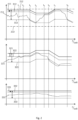
- Figure 2 shows an example for the development over time regarding the feed of the first reactor 21 in the topmost graph, the second reactor 22 in the middle graph and the third reactor 23 in the bottom graph.
- the topmost graph regarding the first reactor 21 shows the actual feed 211, the feed target 311, a first feed-delta 313 and second feed-delta 312 as well as a maximum feed 212 and a minimum feed 213.
- the first feed-delta 313 and the second feed-delta 312 are differences to the feed target 311 as indicated by the double-ended arrows.
- the first and second feed-delta 313 and 312 are further shown as dotted lines illustrating the difference to the feed target 311 over the shown period of time. Until the time t 3 the actual feed 211 is varying below the feed target 311 and within the two dotted lines.
- the difference of the actual feed 211 to the feed target 311 is not larger than the first feed-delta 313 and not smaller than the second feed-delta 312.
- the control unit 3 thus does not interpret these values as an inquiry for either increase or decrease of the feed target 311.
- the control unit 3 thus does not interpret these values as an inquiry for either increase or decrease of the feed target 331.
- the actual feed 221 of the second reactor 22 also starts within the two dotted lines illustrating the first feed-delta 323 and the second feed-delta 322, but crosses the dotted line illustrating the second feed-delta 322 at time t 1 .
- the difference of the actual feed 221 to the feed target 321 is smaller than the second feed-delta 322 at this point and the control unit 3 interprets this as an inquiry for higher feed target 321.
- the control unit 3 then calculates the sum of all the feed targets 311, 321, 331 of the first reactor 21, the second reactor 22 and the third reactor 23 and subtracts this sum from the total feed target comprised in the control unit 3.
- the sum of the feed targets 311, 321 and 331 equals the total feed target and thus there is no free target. Therefore, even though the second reactor inquired for higher feed target 321, the feed target 321 of the second reactor 23 is not increased. This is also the case in the time between t 2 and t 3 .
- the control unit 3 interprets this as an inquiry for a lower feed target 311. Since the feed target 311 of the first reactor 21 is still much higher than the minimum feed 213 of the first reactor 21, the control unit 3 decreases the feed target 311 of the first reactor 21 as long as the actual feed 211 of the first reactor 21 stays below the dotted line illustrating the first feed-delta 313. This results in free target, meaning that the sum of the feed targets 311, 321, 331 of the first, the second and the third reactor 21, 22, 23 is smaller than the total feed target comprised in the control unit 3.
- the control unit 3 Since the second reactor 22 has an actual feed 221 which is still higher than the upper dotted line illustrating the second feed-delta 322 of the second reactor 22, and hence the difference between the actual feed 221 and the feed target 321 of the second reactor 22 is smaller than the second feed-delta 322 of the second reactor 22, the control unit 3 still interprets this as the second reactor 22 inquiring for higher feed target 321. Due to the drop of the feed target 311 of the first reactor 21 and the resulting free target, the control unit 3 can now increase the feed target 321 of the second reactor 22.
- the actual feed 211 of the first reactor 21 raises above the dotted line illustrating the first feed-delta and thus the difference between the actual feed 211 and the feed target 311 of the first reactor 21 is no longer larger than a first feed-delta 313.
- the control unit 3 thus does not interpret this as an inquiry for lower feed target 311 anymore.
- the feet target 311 of the first reactor 21 is thus constant again between t 4 and t 5 .
- the actual feed 211 of the first reactor 21 lies above the dotted line illustrating the second feed-delta 312 and thus the difference between the actual feed 211 and the feed target 311 is smaller than the second feed-delta 312.
- the control unit 3 interprets this as an inquiry for higher feed target 311 of the first reactor 21.
- the sum of the feed targets 311, 321 and 331 of the first, second and third reactor 21, 22 and 23 already equals the total feed target and thus no further increase of the feed target 311 of the first reactor 21 is possible.
- the actual feed 221 of the second reactor 22 drops below the dotted line and thus the difference between the actual feed 221 and the feed target 321 of the second reactor 22 is larger than a first feed delta 323 of the second reactor 22 and hence the control unit 3 decreases the feed target 321 of the second reactor 22. Since the first reactor is still inquiring for higher feed target at this time, the feed target 311 of the first reactor 21 is increased.
- the second reactor 22 is still inquiring for lower feed target 321 and hence the feed target 321 of the second reactor 22 is still decreased creating free feed target.
- the first reactor 21 is still inquiring for a higher feed target 311, since the difference between the actual feed 211 and the feed target 311 is still smaller than the second feed-delta 312, the feed target 311 of the first reactor 21 is not further increased since the feed target 311 has reached the maximum feed 212 of the first reactor 21.
- the control unit 3 decreases the feed target 311 of the first reactor 21. Since no other reactor inquired for a higher feed target at that time, the sum of the feed targets 311, 321 and 331 of the first, the second and the third reactor 21, 22 and 23 is lower than the total feed target comprised in the control unit 3.
- Figure 3 shows a corresponding example for the development over time regarding the air stream of the first reactor 21 in the topmost graph, the second reactor 22 in the middle graph and the third reactor 23 in the bottom graph.
- the topmost graph regarding the first reactor 21 shows the actual air stream 214, which is adjusted by the reactor between the upper airstream threshold 314 and the lower airstream threshold 315.
- the topmost graph further shows a first air-delta 317, which is depicted as an double-ended arrow and a dotted line in the distance of the first air-delta to the depicted lower airstream threshold 315.
- figure 3 shows the second air-delta as a double-ended arrow and a dotted line with the respective distance to the upper airstream threshold 314.
- the upper graph additionally shows a maximum air stream 215 and a minimum air stream 216.
- the allowable air stream range between the lower airstream threshold 315 and the upper airstream threshold 314 is divided in three parts by the first air-delta 317 and the second air-delta 316.
- An upper part where the difference between the actual airstream and the upper air stream threshold is smaller than the second air-delta
- a bottom part where the difference between the actual airstream and the lower air stream threshold is smaller than the first air-delta
- the middle part where the difference between the actual airstream and the upper air stream threshold is larger than the second air-delta and the difference between the actual airstream and the lower air stream threshold is larger than the first air-delta.
- the control unit 3 interprets the reactor as inquiring for a lower threshold.
- the control unit 3 decreases upper and lower airstream thresholds until the time t 7 , when the actual air stream 214 rises again above the lower dotted line, depicting the first air-delta 317.
- the middle graph shows the actual air stream 224 of the second reactor 22 with an upper airstream threshold 324 and a lower airstream threshold 325 of the second reactor 22.
- first and second air-delta 327, 326 of the second reactor 22 are depicted as double-ended arrows and a dotted line.
- the actual air stream 224 stays within the middle part of the allowable range until time t 5 .
- the actual air stream 224 raises above the upper dotted line depicting the second air-delta, 326where the difference between the actual air stream 224 and the upper airstream threshold 324 of the second reactor 22 is smaller than the second air-delta 326 of the second reactor 22.
- the control unit 3 thus increases the air stream thresholds 324, 325.
- the actual air stream 224 of the second reactor 22 is still high enough such that the difference between the actual air stream 224 and the upper airstream threshold 324 is smaller than the second air-delta 326. Since the sum of the air stream thresholds 314, 324, 334 already equal the total air stream threshold comprised in the control unit, the air stream thresholds of the second reactor 22 are not further increased.
- the bottom graph of figure 3 shows the actual air stream 234 of the third reactor 23 as well as the upper airstream threshold 334, lower airstream threshold 335, the first air-delta 337 and second air-delta 336 of the third reactor 23. Since the actual air stream 234 of the third reactor 23 stays in the middle part of the allowable range the whole time, no decrease or increase is performed by the control unit 3.
Landscapes
- Chemical & Material Sciences (AREA)
- Organic Chemistry (AREA)
- Chemical Kinetics & Catalysis (AREA)
- Engineering & Computer Science (AREA)
- Thermal Sciences (AREA)
- Physics & Mathematics (AREA)
- Automation & Control Theory (AREA)
- Geology (AREA)
- Materials Engineering (AREA)
- Mechanical Engineering (AREA)
- Metallurgy (AREA)
- Manufacturing & Machinery (AREA)
- Life Sciences & Earth Sciences (AREA)
- Geochemistry & Mineralogy (AREA)
- General Life Sciences & Earth Sciences (AREA)
- Environmental & Geological Engineering (AREA)
- Physical Or Chemical Processes And Apparatus (AREA)
- Exhaust Gas Treatment By Means Of Catalyst (AREA)
- Hydrogen, Water And Hydrids (AREA)
Description
- The invention relates to a reactor control unit for controlling a plurality of parallel reactors each being fed with at least one reactant with a time depending feed rate, wherein the control unit is configured to communicate at least one control variable to the plurality of reactors, in particular to communicate a set of control variables to each of the plurality of reactors. The invention further relates to a reactor system comprising a plurality of parallel reactors and a control unit for controlling the plurality of parallel reactors as well as a method for controlling a plurality of parallel reactors.
-
US 2014/0017133 A1 discloses an ozone gas supply system with several nitro-gen-free ozone generation units. Each generation unit comprises a nitro-gen-free ozone generator and an ozone control part. In each generation unit, a raw material gas is supplied to the ozone generators through a corresponding gas flow rate controller with a constant flow rate. Process ozone gas event signals are inputted from downstream-side ozone treatment apparatuses to a system management control part and indicate ozone rates, which are requested by said ozone treatment apparatuses. The system management control part outputs nitrogen-free ozone generation unit control signals for controlling the generation units based on the process ozone gas event signals. Each of the nitrogen-free ozone generation unit control signals indicates a request ozone flow rate request ozone concentration and for the respective generation unit. Those values are determined by the system management control part based on the ozone flow rates and ozone concentrations, which are requested by the ozone treatment apparatuses by the process ozone gas event signals. Further, each ozone control part includes an event adjuster for adjusting the set flow rate based on the request ozone flow rate, which is received from the system management control part. -
US 2007/0078238 A1 shows a polymerization system including two polymerization reactors in parallel configuration. Properties of a polyolefin product and a catalyst performance are controlled by adjusting amounts of components directed to a pre-contactor versus amounts of components sent directly to a polymerization reactor via a pre-contactor bypass. Means for feed and control measure and control the rates at which the components are introduced into the polymerization system. These means can be, for example, a flow meter, a pump, or a combination thereof. - According to
RU 2 223 284 C3 -
US 2011/0014718 A1 relates to a method and device for the parallel study of chemical reactions in at least two spatially separated reaction spaces. Especially, it is pointed to reactions in which fluid flows through at least two spatially separated reaction processes, wherein the reactions are controlled together for all reaction spaces. Accordingly, the device has a common educt feed and at least one common holding gas feed for all the reaction spaces. - A continuous polymerization apparatus of
EP 2 481 477 A1 comprises a first reactor and a second reactor. A raw material supply line is located so that a raw material monomer and a polymerization initiator are supplied in the form of a mixture to the reactors via respective supply ports. A flow control valve is located at a branching point, at which a common part of the raw material supply line branches into a first part and a second part, and thereby the flow rates of the mixture passing to the first reactor and the second reactor are controlled. A control unit is provided for adjusting the respective supply amounts of the raw material monomer and the polymerization initiator to the reactors with the operation of pumps for the raw material and the initiator and the flow control valve or by regulating the temperature of an outer surface of the reactors for temperature regulating jackets. The control unit directly controls the supply flow rates for the reactors. -
US 2007/0104641 A1 relates to a method for controlling addition of a supplementary oxygen stream into a steam methane reformer. Several reformer tubes are within one single radiant section of the reformer and are supplied by a common combined stream. -
US 6,489,168 B1 discloses a reactor control system for monitoring and controlling a parallel chemical reaction. The reactor control system sends control data to and receives experimental data from a parallel polymerization reactor. The control and experimental data includes set point values for temperature, pressure, time, stirring speed as well as measured experimental values for temperature and pressure. The reactor control system acquires experimental data in a system control module and processes it in a data analysis module under user control through a user interface module. The system control module controls a reactor vessel pressure through a pressure interface and a pressure controller. The pressure controller pressure control signals to valves allowing gases to enter or exit reactor vessels through inlet/outlet as required to maintain the reactor vessel pressure at a level set by the user through user interface. Further, the reactor control system can determine whether the reaction occurring in one or more of reactor vessels has reached a specified conversion target based on calculated results. In that case, the reactor control system causes the addition of a quenching agent to the relevant reactor vessel or vessels for terminating the reaction in that vessel. -
WO 2018/025201 A1 shows a system for controlling a plant for the production in continuous of a polymer. The plant comprises a reaction section comprising at least one reactor, which is fed with at least a first monomer and a second monomer, a stripping section, comprising a first high-pressure stripper, a second low-pressure stripper and a third low-pressure stripper, a finishing section comprising at least one vat for recycling the fine products, a plurality of measurement equipment of the operating conditions of the plant, and a control system. The control system comprises a plurality of distributed control devices which can be driven by at least one central electronic processing and control unit on the basis of a plurality of control variables comprising the flowrate of oil with which the first stripper is fed, the flowrate of chain terminator with which the at least one reactor is fed, and the vent flowrate of the thermostatic control circuit of reactor. The central electronic processing and control unit comprises software means for implementing a control method. Therein, a production potential value of the reactor is determined. - Reactors, particularly fluidized bed reactors like e.g. roasting reactors, have to be controlled by adjusting a high plurality of parameters. The parameters of the reactors typically include several input material streams like feed material, air, oxygen, additional gases, water and others. The reactors also have output material streams like the product material and exhaust gases. Additionally the reactors have internal parameters like the process temperature or the composition of the various material streams, especially the output stream of the product. At least some of these parameters cannot be directly controlled and/or depend highly on other parameters of the reactor. Also, there are a number of inner boundary conditions, like a maximum or a minimum value or a specific ratio to another parameter. Control units for the adjustable parameters of a single reactor are well established
- However, often a number of reactors form a combined reactor system, sharing some previous or downward system, like feeding lines. Hence, the available feed has to be shared by the reactors. The same is true for output streams, especially the exhaust gas, which is typically treated in a combined exhaust after-treatment system for all the reactors.
- As it is very seldom that all reactors are operated at their maximum, it is common to undersize the supply lines and/or the exhaust system. This means, the supply lines cannot supply all reactors running at full capacity at the same time and/or the exhaust after-treatment system cannot handle the exhaust gases of all reactors running at full capacity at the same time. Therefore, besides the individual requirements the reactor has to fulfill, also global requirements exist that have to be fulfilled by the combination of the reactors. This renders the control of a reactor system comprising a plurality of reactors highly complicated and thus typically such a reactor system does not use all the available resources and does thus not work at the highest possible efficiency.
- It is, therefore, the object of the present invention to improve the efficiency of reactor systems with a plurality of individual reactors.
- The object is solved by a reactor control unit for controlling a plurality of parallel reactors according to
claim 1. - The reactor control unit is configured to communicate at least one control variable to the reactors, wherein the at least one control variable comprises a feed target, which is a threshold value regarding the specific feed rate of the reactor. In particular, the control unit sends one corresponding feed target to every controlled reactor, wherein the reactor can adjust its own actual feed under the condition that it is smaller than the assigned feed target. The feed of the reactor is the amount of input material, put in the reactor, converted therein and output as a product. The feed is therefore more or less proportional to the throughput and the amount of material output of the reactor. The reactor typically tries to maximize its throughput and thus its feed and therefore tries to reach the assigned feed target.
- The control unit comprises a total feed target, which can be a physical restriction of an apparatus arranged subsequently to the plurality of reactors or can be adjusted by a person due to a specific demand, and indicates the total desired feed, which determines the total throughput of the reactors. The total feed target is stored in the control unit as an upper boundary value. The control unit is configured to set the respective feed targets of the plurality of reactors such that the sum of the feed targets of the plurality of reactors is lower or equal to the total feed target. Further, the control unit is configured to read the actual feeds from the plurality of reactors, e.g. the feed values as adjusted by the individual reactors, for example by receiving the values from subordinate control units responsible for the individual reactors or access a corresponding memory of such a control unit. Alternatively, the control unit can have direct access to respective sensor units.
- Depending on the actual feed rate and the feed target of the reactor, the control unit interprets the reactor as inquiring a higher, the same or a lower feed target. It then decreases the feed target for a reactor that inquires a lower feed target and increases the feed target for a reactor that inquires a higher feed target under the condition that the sum of the feed targets does not exceed the total feed target. Thus, the control unit shifts the several feed targets between the plurality of reactors, depending on the actual use of the reactors in order to maximize the total throughput of the system of parallel reactors. The control unit constantly repeats the steps of reading the actual feeds of the reactors and comparing them to the feed targets, determining which reactors inquire a higher and/or lower threshold and increasing and/or decreasing the respective thresholds, when possible. The steps can be repeated by the control unit as fast as possible or with a predetermined periodicity.
- According to a preferred embodiment, the control unit is configured to calculate a difference between the feed target and the actual feed of each reactor, which is adjusted by the reactor itself. When the calculated difference is larger than a first difference stored in the control unit as a first feed-delta, the reactor seems not to be able to reach the assigned target value. The control unit interprets this as the reactor inquiring for a lower feed target. When the reactor actually reaches its target value or nearly reaches its target value, the difference between the feed target and the feed is smaller than a second feed-delta. The second feed delta can be chosen in the order of magnitude of normal fluctuations of the feed and is thus much smaller than the first feed-delta. The control unit interprets this as the reactor inquiring for higher feed target. Hence, the control unit shifts the target feed from a reactor that was not able to reach its target value to a reactor, which seems to be able to reach an even higher feed. This results in a higher total feed and, thus, in an increased overall throughput.
- According to an alternative embodiment, one of the control variables is a lower threshold value regarding the feed of the reactor. The control unit thus sends the feed target as a higher threshold and additionally a lower threshold to the reactor. The reactor has therefore an upper and a lower boundary within which it can adjust its feed. The control unit is configured to calculate a difference between the lower threshold value and the actual feed of each reactor and interpret the reactor as inquiring for lower feed target when a difference between the feed and the lower threshold value regarding the feed of the reactor is smaller than a first feed-delta.
- The control unit is further configured to calculate the difference between the feed target and the actual feed. When the feed lies near the feed target, where a difference between the feed target and the feed is smaller than a second difference stored in the control unit as a second feed-delta, the reactor is interpreted as inquiring for higher feed target. The sum of the first and second feed-delta can be smaller than the difference between the feed target and the lower threshold value. Thus, the area between the upper and lower threshold is divided in three parts. An upper part, interpreted as inquiring for higher threshold, a middle part as inquiring for the same threshold and a bottom part as inquiring for a lower threshold. This two-threshold principle is described later regarding the air stream and oxygen stream in more detail and is also applicable with all its details to the feed target and the lower threshold value regarding the feed of the reactor.
- According to a preferred embodiment the feed targets of the reactors that inquired a higher feed target are increased such that the sum of all feed targets equals the total feed target. Hence, the free feed target, defined as the difference between the sum of all feed targets and the total feed target, is completely distributed to the reactors that inquired a higher feed target. The control unit can decrease the feed target of the reactors that inquired a lower threshold irrespective of other reactors inquiring for a higher target. This will lead to unassigned or free target. In such a case, the sum of all feed targets is lower than the total feed target. Alternatively, the control unit can be configured to decrease the feed target of the reactors that inquired a lower threshold, only, when at least one other reactor inquires for a higher feed target.
- According to a further preferred embodiment the feed targets of the reactors that inquired a higher feed target re increased evenly. Therefore, the free target is distributed evenly to the reactors that inquired a higher feed target. Hence, every reactor that inquired a higher feed target gets the same part of the freed target of a reactor that inquired a lower feed target. The reactors are therefore handled equally, preventing that one reactor has disadvantages due to its position in the control system.
- According to a preferred embodiment the feed target is increased and/or decreased by a fixed step and/or rate. The control unit can comprise a predetermined decrease step for a reactor. The decrease step can be the same or an individual decrease step for every reactor. When the target feed of a reactor that inquired a lower feed target is decreased, the target feed is decreased by this specific step. Likewise, the control unit can comprise a predetermined increase step for a reactor. The increase step can also be the same or an individual increase step for every reactor. When the target feed of a reactor that inquired a higher feed target is increased, the target feed is increased by this specific step. When the free target is not sufficient to increase the feed target of all reactors that inquired a higher feed target by the predetermined step, the control unit can increase the feed target of as many reactors as possible. Alternatively, the feed target of all reactors that inquired a higher feed target can be increased by a reduced step, such that the free feed target is distributed completely. It is also possible to increase and decrease the feed target by a specific rate, meaning by a predetermined value per unit of time. Thereby the speed with which the feed target values change does not depend on the control units calculating power, which affects the repetition rate with which the control unit checks the reactors and sends new feed targets to the reactors. In the same way as above, the control unit can comprise an increase and/or a decrease rate for every individual reactor or a global increase and/or decrease rate for all reactors.
- According to a preferred embodiment of the invention, the control unit comprises a maximum feed for at least one of the plurality of reactors, wherein the control unit is configured to set the feed target of the reactor lower than the maximum feed of the reactor. Hence, the control unit knows the maximum feed values of the plurality of the reactors and sets the feed target accordingly such that it does not exceed the maximum feed of the reactor. Additionally the reactor can be configured to not accept an increase of its feed target that would exceed its maximum feed. Alternatively, the control unit can read the maximum feed from the reactor and set the target feed accordingly, or the control unit can have no information about the maximum feed and set the target feed independently and the reactor itself sets its target value to the maximum feed when a target feed higher than the maximum feed is received.
- Additionally or alternatively, the control unit can comprise a minimum feed for at least one of the plurality of reactors, wherein the control unit is configured to set the feed target of the reactor higher than the minimum feed of the reactor. Hence, the control unit knows the minimum feed values of the plurality of reactors and sets the feed target accordingly such that it does not fall below the minimum feed target. Additionally, the reactor can be configured to not accept a decrease of its feed target that would fall below its minimum feed. Alternatively, the control unit can read the minimum feed from the reactor and set the target feed accordingly, or the control unit can have no information about the minimum feed and set the target feed independently and the reactor itself sets its target value to the minimum feed when a target feed lower than the minimum feed is received.
- According to a preferred embodiment, the at least one control variable comprises a lower and a higher air stream threshold. Hence, the control unit sends a pair of corresponding air stream thresholds preferably to every controlled reactor, wherein the reactor can adjust its own actual air stream under the condition that it stays within the received thresholds. The control unit comprises a total air stream value, wherein the sum of the higher air stream thresholds of the plurality of reactors is lower or equal to the total air stream value. The control unit is further configured to read an actual air stream from the plurality of reactors by receiving the actual air stream values from a single reactor control unit, accessing a corresponding memory, having access to respective sensors or receiving the values in another way. The control unit then compares the actual air stream with the lower and higher air stream thresholds and interprets a difference between the higher air stream threshold and the actual air stream, which is smaller than a first air-delta as an inquiry for increase of the air stream thresholds. Furthermore, the control unit interprets a difference between the lower air stream threshold and the actual air stream, which is smaller than a second air-delta as an inquiry for a decrease of the air stream thresholds.
- The sum of the first and second air-delta can be smaller than the difference between the higher air stream threshold and the lower air stream threshold. Thus, the area between the upper and lower threshold is divided in three parts. An upper part, interpreted as inquiring for higher threshold, a middle part as inquiring for the same threshold and a bottom part as inquiring for a lower threshold. Hence, when the reactor adjusts its air stream such that it lies in the upper part of the allowable field, the control unit interprets it as a request for an increase. On the other hand, when the reactor adjusts its air stream such that it lies in the lower part of the allowable field, the control unit interprets it as a request for a decrease.
- The control unit then decreases the lower and/or higher air stream thresholds for a reactor that inquired a lower air stream threshold and increases the lower and/or higher air stream thresholds for a reactor that inquired a higher air stream threshold under the condition that the total air stream value is not exceeded.
- According to a further preferred embodiment, the total air stream value depends on a maximum gas throughput of a joint exhaust gas after-treatment system, which is arranged after the plurality of reactors. The total air stream value can thus be a fixed value calculated once from the maximum gas throughput of the joint exhaust gas after-treatment system, for example the maximum gas throughput can be used directly or a specific percentage thereof. Alternatively, the total air stream value is further depending on an oxygen stream value of the plurality of reactors. Since the air stream and the oxygen stream both add to the total exhaust volume, the total air stream value can be constantly adapted to the varying oxygen stream. It could further be adapted based on the composition of the feed material, in particular to the percentage of components that result in larger exhaust volumes.
- According to another preferred embodiment, the control unit comprises a maximum air stream for at least one of the plurality of reactors, wherein the control unit is configured to set the lower and/or higher air stream thresholds of the reactor lower than the maximum air stream of the reactor. Hence, the control unit knows every maximum air stream of the reactors and sets the air stream thresholds accordingly such that the higher air stream threshold does not exceed the maximum air stream. Additionally the reactor can be configured to not accept an increase of its air stream thresholds that would exceed its maximum air stream.
- Alternatively, the control unit can read the maximum air stream from the reactor and set the air stream thresholds accordingly, or the control unit can have no information about the maximum air stream and set the air stream thresholds independently and the reactor itself sets its air stream thresholds to the highest possible values when a value with a higher air stream threshold that exceeds the maximum threshold is received.
- Additionally or alternatively, the control unit can comprise a minimum air stream for at least one of the plurality of reactors, wherein lower and/or higher air stream thresholds of the reactor are set to be higher than the minimum air stream of the reactor. Hence, the control unit knows every minimum air stream of the reactors and sets the air stream thresholds accordingly such that the lower air stream threshold does not fall below the minimum air stream. Additionally, the reactor can be configured to not accept a decrease of its air stream thresholds below its minimum air stream.
- Alternatively, the control unit can read the minimum air stream from the reactor and set the air stream thresholds accordingly, or the control unit can have no information about the minimum air stream and set the air stream thresholds independently and the reactor itself sets its air stream thresholds to the lowest values possible, when a lower air stream threshold lower than the minimum air stream is received.
- According to a preferred embodiment of the invention, the lower air stream threshold has a predetermined difference to the higher air stream threshold and the two values are therefore shifted in parallel, when increased or decreased. Alternatively or additionally higher and lower air stream threshold can be linked by a predetermined factor preferably between 0.6 and 0.95, even more preferred between 0.7 and 0.9, in particular 0.8. Both of these alternatives can be used in turns. In particular the control unit can switch from a predetermined difference to a factor and vice versa, depending on operating parameters of the reactor. Therefore, only one of the values needs to be handled by the control unit whereas the other value is simply updated accordingly, reducing the workload on the control unit.
- According to another preferred embodiment of the invention, the at least one control variable comprises a lower and a higher oxygen stream threshold. Hence, the control unit is configured to send a pair of corresponding oxygen stream thresholds preferably to every controlled reactor, wherein the reactor can adjust its own actual oxygen stream under the condition that it stays within the received thresholds. The control unit comprises a total oxygen stream value, wherein the sum of the higher oxygen stream thresholds of the plurality of reactors is lower or equal to the total oxygen stream value. The total oxygen stream value can be the maximum possible oxygen supply of an oxygen supply unit common for the plurality of reactors. The control unit is configured to read the actual oxygen streams from the plurality of reactors, compare the actual oxygen streams with the lower and higher oxygen stream thresholds, interpret a difference between the higher oxygen stream threshold and the actual oxygen stream which is smaller than a first oxygen-delta as an inquiry for increase of the oxygen stream thresholds and interpret a difference between the lower oxygen stream threshold and the actual oxygen stream which is smaller than a second oxygen-delta as an inquiry for decrease of the oxygen stream thresholds. The sum of first and second oxygen delta can be smaller than the difference between lower and higher oxygen stream threshold. The control unit is further configured to decrease the lower and/or higher oxygen stream thresholds for a reactor that inquired a lower oxygen stream and increase the lower and/or higher oxygen stream thresholds for a reactor that inquired a higher threshold under the condition that the total oxygen stream value is not exceeded.
- According to another preferred embodiment, the control unit comprises a maximum oxygen stream for at least one of the plurality of reactors, wherein the control unit is configured to set the lower and/or higher oxygen stream thresholds of the reactor lower than the maximum oxygen stream of the reactor. Hence, the control unit knows every maximum oxygen stream of the reactors and sets the oxygen stream thresholds accordingly such that the higher oxygen stream threshold does not exceed the maximum oxygen stream. Additionally the reactor can be configured to not accept an increase of its oxygen stream thresholds that would exceed its maximum oxygen stream.
- Alternatively, the control unit can read the maximum oxygen stream from the reactor and set the oxygen stream thresholds accordingly, or the control unit can have no information about the maximum oxygen stream and set the oxygen stream thresholds independently and the reactor itself sets its oxygen stream thresholds to the highest possible values when a value with a higher oxygen stream threshold that exceeds the maximum oxygen stream is received.
- Additionally or alternatively, the control unit can comprise a minimum oxygen stream for at least one of the plurality of reactors, wherein lower and/or higher oxygen stream thresholds of the reactor are set to be higher than the minimum oxygen stream of the reactor. Hence, the control unit knows every minimum oxygen stream of the reactors and sets the oxygen stream thresholds accordingly such that the lower oxygen stream threshold does not fall below the minimum oxygen stream. Additionally, the reactor can be configured to not accept a decrease of its oxygen stream thresholds below its minimum oxygen stream. Alternatively, the control unit can read the minimum oxygen stream from the reactor and set the oxygen stream thresholds accordingly, or the control unit can have no information about the minimum oxygen stream and set the oxygen stream thresholds independently and the reactor itself sets its oxygen stream thresholds to the lowest values possible, when a lower oxygen stream threshold lower than the minimum oxygen stream is received.
- The start-up procedure can be handled such that the reactors are already running, when their control is shifted to the inventive control unit. The control unit can read the parameters like the actual feed, air stream and oxygen stream and accept the control over the reactors only, when the parameters are within required margins like not exceeding the total feed target, the total air stream and/or the total oxygen stream.
- The reactor system comprises a plurality of parallel reactors and a control unit communicating control variables to the reactors, wherein the control unit is a control unit as described above. The reactors are self-controlled and adjust their parameters according to their inner boundary conditions, like the temperature, the ratios between air, oxygen, feed, sulfur concentration in the feed or other parameters, and the control variables received from the control unit. Preferably, the reactors are configured to maximize the feed of the reactor and thus the throughput.
- According to a preferred embodiment of the inventive reactor system, at least one of the plurality of reactors, in particular all reactors are roasting reactors, in particular fluidized bed reactors.
- According to another preferred embodiment of the inventive reactor system the reactors have a joint exhaust gas after-treatment system with a maximum gas throughput lower than the sum of the maximum exhaust gas outputs of the plurality of reactors. Hence, when all reactors would run on 100 percent, the exhaust system would be overloaded. Since the reactors are controlled by the inventive control unit, such an overload is prevented.
- The object is also solved by a method for controlling combined reactor system according to claim 16.
- The reactor system comprises a plurality of parallel reactors, wherein a control unit communicates control variables to the reactors, and one of the control variables is a feed target, which is a threshold value regarding the feed of the reactor. The plurality of reactors adjust their parameters according to their inner boundary conditions and the received control variables in order to maximize the target value. The control unit comprises a total feed target and sets the respective feed targets for the plurality of reactors such that the sum of the feed targets of the plurality of reactors is lower or equal to the total feed target. Further, the control unit reads the actual feeds from the plurality of reactors, compares the actual feeds with the feed targets, and based on the comparison interprets the reactor as inquiring for a higher, the same or a lower feed target. The control unit then decreases the feed target for a reactor that inquired a lower threshold and increases the feed target for a reactor that inquired a higher threshold under the condition that the total feed target is not exceeded. The inventive method can comprise all the steps described above with regard to the control unit and the reactor system.
- Further objectives, features, advantages and possible applications of the invention can also be taken from the following description of the attached drawings and the example. All features described and/or illustrated form the subject matter of the invention per se or in any combination, independent of their inclusion in the individual claims or their back-references.
- In the drawings:
-
Fig. 1 shows a schematic view of the inventive reactor system -
Fig. 2 shows a graph of the feed control of three reactors of the inventive reactor system, -
Fig. 3 shows a graph of the oxygen stream control of three reactors of the inventive reactor system; - The
inventive reactor system 1 shown inFig. 1 comprises threereactors first reactor 21 has afeed input 41, which is connected to atotal feed supply 4, anoxygen stream input 51, which is connected to anoxygen supply unit 5 and anair stream input 61, which is connected to a totalair stream supply 6. Likewise, thesecond reactor 22 has afeed input 42, which is connected to thetotal feed supply 4, anoxygen stream input 52, which is connected to theoxygen supply unit 5 and anair stream input 62, which is connected to the totalair stream supply 6. Thethird reactor 23 has afeed input 43, which is connected to thetotal feed supply 4, anoxygen stream input 53, which is connected to theoxygen supply unit 5 and anair stream input 63, which is connected to the totalair stream supply 6. -
First reactor 21 has anoutput 71 of the produced material, which adds up with theoutput 72 of thesecond reactor 22 and theoutput 73 of thethird reactor 23 to thetotal output 7. - The
exhaust gases 81 of thefirst reactor 21, theexhaust gases 82 of thesecond reactor 22 and theexhaust gases 83 of thethird reactor 23 are guided to a common exhaust after-treatment system 8. - A
control unit 3 controls thefirst reactor 21, thesecond reactor 22 and thethird reactor 23 by sendingcontrol variables 31 to thefirst reactor 21,control variables 32 to thesecond reactor 22 andcontrol variables 33 to thethird reactor 23. Furthermore, thecontrol unit 3 readsparameters 34 of thefirst reactor 21,parameters 35 of thesecond reactor 22 andparameters 36 of thethird reactor 23. Thecontrol variables feed target upper airstream threshold lower airstream threshold - The
reactors feeds feed targets airstreams air stream thresholds - The
control unit 3 reads anactual feed 211,air stream 214 and oxygen stream asparameters 34 from thefirst reactor 21. Likewise, thecontrol unit 3 reads theactual feeds air stream second reactor 22 and third reactor asparameters - The
control unit 3 knows the actual demand for thetotal output 7, which is saved as a total feed target in thecontrol unit 3. Furthermore, the maximum exhaust volume of the exhaust after-treatment system 8 is saved as a total air stream value in thecontrol unit 3 and the maximum possible oxygen supply of theoxygen supply unit 5 is saved in thecontrol unit 3 as a total oxygen stream value. - The control unit periodically performs control steps, for example every 10 seconds, where it reads the
actual feed 211 of thefirst reactor 21 as part of itsparameters 34. Thecontrol unit 3 than checks whether theactual feed 211 lies in an upper part of the allowable feed range in that it calculates the difference of thefeed target 311 and theactual feed 211 and compares the difference to a second feed-delta 312. If the difference is smaller than the second feed-delta 312, theactual feed 211 lies in an upper part of the allowable feed range and thecontrol unit 3 interprets this as thereactor 21 inquiring ahigher feed target 311. The control unit also checks, whether theactual feed 211 lies in a lower part of the allowable feed range in that it compares the calculated difference of thefeed target 311 and theactual feed 211 and compares it to a first feed-delta 313. If the difference is larger than the first feed-delta 313, theactual feed 211 lies in a lower part of the allowable feed range and thecontrol unit 3 interprets this as thereactor 21 inquiring alower feed target 311. Thecontrol unit 3 performs the same control step for thesecond reactor 22 and thethird reactor 23. - The
control unit 3 than decreases thefeed target reactors lower feed target feed target minimum feed 213 of therespective reactor control unit 3 than increases thefeed target reactors higher feed target feed target maximum feed 212 of therespective reactor reactors - The control unit also reads the
actual air stream 214 of thefirst reactor 21 as part of itsparameters 34. Thecontrol unit 3 than checks whether theactual air stream 214 lies in an upper part of the allowable air stream range in that it calculates the difference of the upperair stream threshold 314 and theactual air stream 214 and compares the difference to a second air-delta 316. If the difference is smaller than the second air-delta 316, theactual air stream 214 lies in an upper part of the allowable air stream range and thecontrol unit 3 interprets this as thereactor 21 inquiring higherair stream thresholds control unit 3 also checks, whether theactual air stream 214 lies in a lower part of the allowable air stream range in that it calculates the difference of the lowerair stream threshold 315 and theactual air stream 214 and compares the difference to a first air-delta 317. If the difference is smaller than the first air stream-delta 317, theactual air stream 214 lies in a lower part of the allowable air stream range and thecontrol unit 3 interprets this as thereactor 21 inquiring lowerair stream thresholds control unit 3 performs the same step regarding the air stream for thesecond reactor 22 and thethird reactor 23. - The
control unit 3 than decreases theair stream thresholds reactors air stream thresholds air stream thresholds minimum air stream 216 of therespective reactor control unit 3 than increases theair stream thresholds reactors air stream thresholds air stream thresholds maximum air stream 215 of therespective reactor air stream thresholds reactors - The control unit also reads the actual oxygen stream of the
first reactor 21 as part of itsparameters 34. Thecontrol unit 3 than checks whether the actual oxygen stream lies in an upper part of the allowable oxygen stream range in that it calculates the difference of the upper oxygen stream threshold and the actual oxygen stream and compares the difference to a second oxygen-delta. If the difference is smaller than the second oxygen-delta, the actual oxygen stream lies in an upper part of the allowable oxygen stream range and thecontrol unit 3 interprets this as thereactor 21 inquiring higher oxygen stream thresholds. Thecontrol unit 3 also checks, whether the actual oxygen stream lies in a lower part of the allowable oxygen stream range in that it calculates the difference of the lower oxygen stream threshold and the actual oxygen stream and compares the difference to a first oxygen-delta. If the difference is smaller than the first oxygen stream-delta, the actual oxygen stream lies in a lower part of the allowable oxygen stream range and thecontrol unit 3 interprets this as thereactor 21 inquiring lower oxygen stream thresholds. Thecontrol unit 3 performs the same steps regarding the oxygen stream for thesecond reactor 22 and thethird reactor 23. - The
control unit 3 than decreases the oxygen stream thresholds of all thereactors respective reactor control unit 3 than increases the oxygen stream thresholds of all thereactors respective reactor reactors -
Figure 2 shows an example for the development over time regarding the feed of thefirst reactor 21 in the topmost graph, thesecond reactor 22 in the middle graph and thethird reactor 23 in the bottom graph. - The topmost graph regarding the
first reactor 21 shows theactual feed 211, thefeed target 311, a first feed-delta 313 and second feed-delta 312 as well as amaximum feed 212 and aminimum feed 213. The first feed-delta 313 and the second feed-delta 312 are differences to thefeed target 311 as indicated by the double-ended arrows. The first and second feed-delta feed target 311 over the shown period of time. Until the time t3 theactual feed 211 is varying below thefeed target 311 and within the two dotted lines. Hence, the difference of theactual feed 211 to thefeed target 311 is not larger than the first feed-delta 313 and not smaller than the second feed-delta 312. Thecontrol unit 3 thus does not interpret these values as an inquiry for either increase or decrease of thefeed target 311. - The same is true for the
third reactor 23 over the complete shown period of time. Theactual feed 231 of thethird reactor 23 is varying below thefeed target 331 and within the two dotted lines illustrating the first and second feed-delta actual feed 231 to thefeed target 331 is not larger than the first feed-delta 333 and not smaller than the second feed-delta 332. Thecontrol unit 3 thus does not interpret these values as an inquiry for either increase or decrease of thefeed target 331. - The
actual feed 221 of thesecond reactor 22 also starts within the two dotted lines illustrating the first feed-delta 323 and the second feed-delta 322, but crosses the dotted line illustrating the second feed-delta 322 at time t1. Hence, the difference of theactual feed 221 to thefeed target 321 is smaller than the second feed-delta 322 at this point and thecontrol unit 3 interprets this as an inquiry forhigher feed target 321. Thecontrol unit 3 then calculates the sum of all the feed targets 311, 321, 331 of thefirst reactor 21, thesecond reactor 22 and thethird reactor 23 and subtracts this sum from the total feed target comprised in thecontrol unit 3. In the shown example offigure 2 , the sum of the feed targets 311, 321 and 331 equals the total feed target and thus there is no free target. Therefore, even though the second reactor inquired forhigher feed target 321, thefeed target 321 of thesecond reactor 23 is not increased. This is also the case in the time between t2 and t3. - At the time t3, the
actual feed 211 of thefirst reactor 21 drops below the lower dotted line and hence the difference of theactual feed 211 to thefeed target 311 is larger than the first feed-delta 313 and thecontrol unit 3 interprets this as an inquiry for alower feed target 311. Since thefeed target 311 of thefirst reactor 21 is still much higher than theminimum feed 213 of thefirst reactor 21, thecontrol unit 3 decreases thefeed target 311 of thefirst reactor 21 as long as theactual feed 211 of thefirst reactor 21 stays below the dotted line illustrating the first feed-delta 313. This results in free target, meaning that the sum of the feed targets 311, 321, 331 of the first, the second and thethird reactor control unit 3. - Since the
second reactor 22 has anactual feed 221 which is still higher than the upper dotted line illustrating the second feed-delta 322 of thesecond reactor 22, and hence the difference between theactual feed 221 and thefeed target 321 of thesecond reactor 22 is smaller than the second feed-delta 322 of thesecond reactor 22, thecontrol unit 3 still interprets this as thesecond reactor 22 inquiring forhigher feed target 321. Due to the drop of thefeed target 311 of thefirst reactor 21 and the resulting free target, thecontrol unit 3 can now increase thefeed target 321 of thesecond reactor 22. - At the time t4, the
actual feed 211 of thefirst reactor 21 raises above the dotted line illustrating the first feed-delta and thus the difference between theactual feed 211 and thefeed target 311 of thefirst reactor 21 is no longer larger than a first feed-delta 313. Thecontrol unit 3 thus does not interpret this as an inquiry forlower feed target 311 anymore. The feet target 311 of thefirst reactor 21 is thus constant again between t4 and t5. - From the time t5, the
actual feed 211 of thefirst reactor 21 lies above the dotted line illustrating the second feed-delta 312 and thus the difference between theactual feed 211 and thefeed target 311 is smaller than the second feed-delta 312. Thecontrol unit 3 interprets this as an inquiry forhigher feed target 311 of thefirst reactor 21. Again, the sum of the feed targets 311, 321 and 331 of the first, second andthird reactor feed target 311 of thefirst reactor 21 is possible. - At the time t6, the
actual feed 221 of thesecond reactor 22 drops below the dotted line and thus the difference between theactual feed 221 and thefeed target 321 of thesecond reactor 22 is larger than afirst feed delta 323 of thesecond reactor 22 and hence thecontrol unit 3 decreases thefeed target 321 of thesecond reactor 22. Since the first reactor is still inquiring for higher feed target at this time, thefeed target 311 of thefirst reactor 21 is increased. - At time t7, the
second reactor 22 is still inquiring forlower feed target 321 and hence thefeed target 321 of thesecond reactor 22 is still decreased creating free feed target. Even though thefirst reactor 21 is still inquiring for ahigher feed target 311, since the difference between theactual feed 211 and thefeed target 311 is still smaller than the second feed-delta 312, thefeed target 311 of thefirst reactor 21 is not further increased since thefeed target 311 has reached themaximum feed 212 of thefirst reactor 21. - At the time t8 the
actual feed 211 of thefirst reactor 21 drops below the first feed-delta 313 again and thus thecontrol unit 3 decreases thefeed target 311 of thefirst reactor 21. Since no other reactor inquired for a higher feed target at that time, the sum of the feed targets 311, 321 and 331 of the first, the second and thethird reactor control unit 3. -
Figure 3 shows a corresponding example for the development over time regarding the air stream of thefirst reactor 21 in the topmost graph, thesecond reactor 22 in the middle graph and thethird reactor 23 in the bottom graph. - The topmost graph regarding the
first reactor 21 shows theactual air stream 214, which is adjusted by the reactor between theupper airstream threshold 314 and thelower airstream threshold 315. The topmost graph further shows a first air-delta 317, which is depicted as an double-ended arrow and a dotted line in the distance of the first air-delta to the depictedlower airstream threshold 315. Furthermore,figure 3 shows the second air-delta as a double-ended arrow and a dotted line with the respective distance to theupper airstream threshold 314. Furthermore, the upper graph additionally shows amaximum air stream 215 and aminimum air stream 216. - The allowable air stream range between the
lower airstream threshold 315 and theupper airstream threshold 314 is divided in three parts by the first air-delta 317 and the second air-delta 316. An upper part, where the difference between the actual airstream and the upper air stream threshold is smaller than the second air-delta, a bottom part, where the difference between the actual airstream and the lower air stream threshold is smaller than the first air-delta and the middle part, where the difference between the actual airstream and the upper air stream threshold is larger than the second air-delta and the difference between the actual airstream and the lower air stream threshold is larger than the first air-delta. - Until the time t5 the
actual air stream 214 of thefirst reactor 21 stays within the two dotted lines and thus in the middle part of the allowable range between thelower airstream threshold 315 and theupper airstream threshold 314, in which thecontrol unit 3 interprets the reactor as not inquiring for a higher or a lower threshold. - At time t5, the actual air stream falls below the lower dotted line and thus in the bottom part, where the difference between the
actual air stream 214 and thelower airstream threshold 315 is smaller than the first air-delta 317 and thecontrol unit 3 interprets the reactor as inquiring for a lower threshold. Thecontrol unit 3 decreases upper and lower airstream thresholds until the time t7, when theactual air stream 214 rises again above the lower dotted line, depicting the first air-delta 317. - The middle graph shows the
actual air stream 224 of thesecond reactor 22 with anupper airstream threshold 324 and alower airstream threshold 325 of thesecond reactor 22. Again, first and second air-delta second reactor 22 are depicted as double-ended arrows and a dotted line. Theactual air stream 224 stays within the middle part of the allowable range until time t5. At this time theactual air stream 224 raises above the upper dotted line depicting the second air-delta, 326where the difference between theactual air stream 224 and theupper airstream threshold 324 of thesecond reactor 22 is smaller than the second air-delta 326 of thesecond reactor 22. Thecontrol unit 3 thus increases theair stream thresholds actual air stream 224 of thesecond reactor 22 is still high enough such that the difference between theactual air stream 224 and theupper airstream threshold 324 is smaller than the second air-delta 326. Since the sum of theair stream thresholds second reactor 22 are not further increased. - The bottom graph of
figure 3 shows theactual air stream 234 of thethird reactor 23 as well as theupper airstream threshold 334,lower airstream threshold 335, the first air-delta 337 and second air-delta 336 of thethird reactor 23. Since theactual air stream 234 of thethird reactor 23 stays in the middle part of the allowable range the whole time, no decrease or increase is performed by thecontrol unit 3. -
- 1
- reactor system
- 21
- first reactor
- 22
- second reactor
- 23
- third reactor
- 3
- control unit
- 31
- control variables first reactor
- 32
- control variables second reactor
- 33
- control variables third reactor
- 4
- total feed supply
- 41
- feed input first reactor
- 42
- feed input second reactor
- 43
- feed input third reactor
- 5
- oxygen supply unit
- 51
- oxygen stream input first reactor
- 52
- oxygen stream input second reactor
- 53
- oxygen stream input third reactor
- 6
- total air supply
- 61
- air stream input first reactor
- 62
- air stream input second reactor
- 63
- air stream input third reactor
- 7
- total output
- 71
- output first reactor
- 72
- output second reactor
- 73
- output third reactor
- 8
- exhaust gas after-treatment
- 81
- exhaust first reactor
- 82
- exhaust second reactor
- 83
- exhaust third reactor
- 211
- actual feed first reactor
- 212
- maximum feed first reactor
- 213
- minimum feed first reactor
- 214
- actual air stream first reactor
- 215
- maximum air stream first reactor
- 216
- minimum air stream first reactor
- 221
- actual feed second reactor
- 224
- actual air stream second reactor
- 231
- actual feed third reactor
- 234
- actual air stream third reactor
- 311
- feed target first reactor
- 312
- second feed-delta first reactor
- 313
- first feed-delta first reactor
- 314
- upper air stream threshold first reactor
- 315
- lower air stream threshold first reactor
- 316
- second air-delta first reactor
- 317
- first air-delta first reactor
- 321
- feed target second reactor
- 322
- second feed-delta second reactor
- 323
- first feed-delta second reactor
- 324
- upper air stream threshold second reactor
- 325
- lower air stream threshold second reactor
- 326
- second air-delta second reactor
- 327
- first air-delta second reactor
- 331
- feed target third reactor
- 332
- second feed-delta third reactor
- 333
- first feed-delta third reactor
- 334
- upper air stream threshold third reactor
- 335
- lower air stream threshold third reactor
- 336
- second air-delta third reactor
- 337
- first air-delta third reactor
Claims (28)
- Combined reactor system (1) comprisingat least two of parallel reactors (21, 22, 23), each of the reactors (21, 22, 23) being fed with at least one reactant with a respective time depending actual feed rate (211, 221, 231), wherein the reactors (21, 22, 23) share• a total feed supply (4), wherein the total feed supply (4) cannot supply all the reactors (21, 22, 23) running at full capacity at the same time, and/or• a joint exhaust after-treatment system (8), wherein the joint exhaust after-treatment system (8) cannot handle exhaust gases (81, 82, 83) of all reactors (21, 22, 23) running at full capacity at the same time, anda control unit (3) configured to communicate, to each of the reactors (21, 22, 23), respectively at least one control variable (21, 22, 23) for the reactor (21, 22, 23);wherein each of the control variables (31, 32, 33) comprises a feed target (311, 321, 331) for the respective reactor (21, 22, 23), which is a threshold value regarding the actual feed rate (211, 221, 231) of said respective reactor (21, 22, 23),wherein the reactors (21, 22, 23) are self-controlled and are configured to adjust their parameters (34, 35, 36, 211, 214, 221, 224, 231, 234) according to their inner boundary conditions and the respective at least one control variable (31, 32, 33) received from the control unit (3), wherein each reactor (21, 22, 23) is configured to adjust its own actual feed rate (211, 221, 231) under the condition that its actual feed reed (211, 221, 231) is smaller than the feed target (311, 321, 331) for this reactor (21, 22, 23) and to maximize its actual feed rate (211, 221, 231) and therefor tries to reach its feed target (311, 321, 331),wherein a total feed target is stored in the control unit (3) as an upper boundary value, wherein the total feed target indicates a total desired feed of the reactors (21, 22, 23), which determines a total throughput of the reactors (21, 22, 23),wherein the control unit (3) is configured such that a sum of the feed targets (311, 321, 331) communicated to the reactors (21, 22, 23) is lower or equal to the total feed target,wherein the control unit (3) is configured to constantly repeat the steps of:• reading the actual feed rates (211, 221, 231) of the plurality of reactors (21, 22, 23) by receiving values of the actual feed rates (211, 221, 231) from subordinate control units responsible for the individual reactors (21, 22, 23) or by access to corresponding memories of such subordinate control units,• for each of the reactors (21, 22, 23), interpreting the respective reactor (21, 22, 23), depending on the actual feed rate (211, 221, 231) of and the feed target (311, 321 331) for the respective reactor (21, 22, 23) as inquiring a higher, the same, or a lower feed target (311, 321, 331), and• decreasing the feed target (311, 321, 311) for those of the reactors (21, 22, 23) that inquire a lower feed target (311, 321, 331) and increasing the feed target (311, 321, 331) those of the reactors (21, 22, 23) that inquires a higher feed target (311, 321, 331) under the condition that the sum of the feed targets (311, 321, 331) for the reactors (21, 22, 23) does not exceed the total feed target,wherein the control unit (3) shifts the feed targets (311, 321, 331) between the reactors (21, 22, 23) depending on an actual use of the reactors (21, 22, 23) in order to maximize the total throughout of the reactors (21, 22, 23).
- Combined reactor system (1) according to claim 1, characterized in that the control unit (3) is configured to calculate a difference between the feed target (311, 321, 331) and the actual feed rate (211, 221, 231) of each reactor (21, 22, 23) and interprets the reactor (21, 22, 23) as inquiring for a lower feed target (311, 321, 331), when the difference is larger than a first difference stored in the control unit (3) as a first feed-delta (313, 323, 333), and the control unit (3) interprets the reactor (21, 22, 23) as inquiring for higher feed target (311, 321, 331), when the calculated difference between the feed target (311, 321, 331) and the actual feed rate (211, 221, 231) is smaller than a second difference stored in the control unit (3) as a second feed-delta (312, 322, 332).
- Combined reactor system (1) according to claim 1, characterized in that the at least one control variable (31, 32, 33) comprises a lower threshold value regarding the actual feed rate of the reactor (21, 22, 23), and that the control unit (3) is configured to calculate a difference between the lower threshold value and the actual feed rate of each reactor (21, 22, 23) and interpret a difference, which is smaller than a first difference stored in the control unit (3) as a first feed-delta as the reactor (21, 22, 23) inquiring a lower feed target and that the control unit (3) is configured to calculate a difference between the feed target and the actual feed rate of each reactor (21, 22, 23) and interpret a difference, which is smaller than a second difference stored in the control unit (3) as a second feed-delta as the reactor (21, 22, 23) inquiring a higher feed target.
- Combined reactor system (1) according to any of the preceding claims, characterized in that the feed targets (311, 321, 331) of all reactors (21, 22, 23) inquiring a higher feed target (311, 321, 331) are increased such that the sum of all feed targets (311, 321, 331) equals the total feed target.
- Combined reactor system (1) according to claim 4, characterized in that the feed targets (311, 321, 331) of the reactors (21, 22, 23) inquiring a higher feed target (311, 321, 331) are increased evenly.
- Combined reactor system (1) according to any of claims 1 to 3, characterized in that the feed target (311, 321, 331) is increased and/or decreased by a fixed step or rate.
- Combined reactor system (1) according to any of the preceding claims, characterized in that the control unit (3) comprises a maximum feed (212) for at least one of the plurality of reactors (21, 22, 23), wherein the control unit (3) is configured to set the feed target (311) of the reactor (21) lower than the maximum feed (212) of the reactor (21) and/or comprises a minimum feed (213) for at least one of the plurality of reactors (21, 22, 23), wherein the feed target (311) of the reactor (21) is set to be higher than the minimum feed (213) of the reactor (21).
- Combined reactor system (1) according to any of the preceding claims, characterized in that the at least one control variable (31, 32, 33) comprises a lower air stream threshold (315, 325, 335) and a higher air stream threshold (314, 324, 334) and the control unit (3) comprises a total air stream value, wherein a sum of the higher air stream thresholds (315, 325, 335) of the plurality of reactors (21, 22, 23) is lower or equal to the total air stream value, wherein the control unit (3) is configured to, for each reactor (21, 22, 23),• read an actual air stream value (214, 224, 234) of the respective reactor (21, 22, 23), compare the actual air stream value (214, 224, 234) with the lower and higher air stream threshold (314, 315, 324, 325, 334, 335) of the reactor (21, 22, 23) by calculating the differences,• interpret the difference between the higher air stream threshold (314, 324, 334) and the actual air stream value (214, 224, 234) being smaller than a second air-delta (316, 326, 336) as an inquiry for increase of the air stream thresholds (314, 315, 324, 325, 334, 335), and• interpret the difference between the lower air stream threshold (315, 325, 335) and the actual air stream value (214, 224, 234) being smaller than a first air-delta (317, 327, 337) as an inquiry for a decrease of the air stream thresholds (314, 315, 324, 325, 334, 335),and wherein the control unit (3) is configured to decrease the lower and/or the higher air stream thresholds (314, 315, 324, 325, 334, 335) for those of the reactors (21, 22, 23) that inquired decrease of the air stream thresholds (314, 315, 324, 325, 334, 335) and increase the lower and/or higher air stream thresholds (314, 315, 324, 325, 334, 335) for those of the reactors that inquired increase of the air stream thresholds (314, 315, 324, 325, 334, 335) under the condition that the total air stream value is not exceeded.
- Combined reactor system (1) according to claim 8, characterized in that the total air stream value depends on a maximum gas throughput of a joint exhaust gas after-treatment system (8) arranged after the plurality of reactors (21, 22, 23), wherein the total air stream value is a fixed value or is further depending on an oxygen stream value of reactors (21, 22, 23).
- Combined reactor system (1) according to claim 8 or 9, characterized in that the control unit (3) comprises a maximum air stream value (215) for at least one of the reactors (21, 22, 23), wherein the control unit (3) is configured to set the lower and/or higher air stream thresholds (314, 315) of the reactor (21) lower than the maximum air stream value (215) of the reactor (21) and/or comprises a minimum air stream value (216) for at least one of the reactors (21, 22, 23), wherein the control unit (3) is configured to set lower and/or higher air stream thresholds (314, 315) of the reactor (21) to be higher than the minimum air stream value (216) of the reactor (21).
- Combined reactor system (1) according to any of the claims 8 to 10, characterized in that the lower air stream threshold (315, 325, 335) has a predetermined difference to the higher air stream threshold (314, 324, 334) for the same reactor (21, 22, 23) and/or a predetermined factor between 0.6 and 0.95, preferably between 0.7 and 0.9, in particular 0.8.
- Combined reactor system (1) according to any of the preceding claims, characterized in that, for each of the reactors (21, 22, 23), the respective at least one control variable (31, 32, 33) comprises a lower and a higher oxygen stream threshold, wherein the control unit (3) comprises a total oxygen stream value, wherein a sum of the higher oxygen stream thresholds of the plurality of reactors (21, 22, 23) is lower or equal to the total oxygen stream value,that the control unit (3) is configured to, for each of the reactors (21, 22, 23),• read an actual oxygen stream value from the respective reactor, compare the actual oxygen stream value with the lower and higher oxygen stream threshold of the reactor (21, 22, 23) by calculating the differences,• interpret the difference between the higher oxygen stream threshold and the actual oxygen stream value being smaller than a first oxygen-delta as an inquiry for increase of the oxygen stream thresholds and• interpret the difference between the lower oxygen stream threshold and the actual oxygen stream value being smaller than a second oxygen-delta as an inquiry for decrease of the oxygen stream thresholds,and wherein the control unit (3) is configured to decrease the lower and/or higher oxygen stream thresholds for those of the reactors (21, 22, 23) that inquired lower oxygen stream thresholds and increases the lower and/or higher oxygen stream thresholds for those of the reactors (21, 22, 23) that inquired higher oxygen stream thresholds under the condition that the total oxygen stream value is not exceeded.
- Combined reactor system (1) according to claim 12, characterized in that the control unit (3) comprises a maximum oxygen stream value for at least one of the reactors (21, 22, 23) or is configured to read the maximum oxygen stream value from the reactor (21, 22, 23), wherein the control unit (3) is configured to set the lower and/or higher oxygen stream thresholds of the reactor (21, 22, 23) lower than the maximum oxygen stream value of the reactor (21, 22, 23) and/or that the control unit (3) comprises a minimum oxygen stream value for at least one of the reactors (21, 22, 23) or is configured to read the minimum oxygen stream value from this reactor (21, 22, 23), wherein the control unit (3) is configured to set lower and/or higher oxygen stream thresholds of the reactor (21, 22, 23) to be higher than the minimum oxygen stream value of the reactor (21, 22, 23).
- Combined reactor system (1) according to any of the preceding claims, characterized in that at least one of the reactors (21, 22, 23), in particular all reactors (21, 22, 23), are roasting reactors, in particular fluidized bed reactors.
- Combined reactor system (1) according to any of the preceding claims, characterized in that the joint exhaust gas after-treatment system (8) has a maximum gas throughput lower than a sum of maximum exhaust gas outputs of the plurality of reactors (21, 22, 23) and/or the reactors (21, 22, 23) have a joint oxygen supply (5) with a maximum oxygen volume lower than a sum of the maximum demands of the plurality of reactors (21, 22, 23).
- Method for controlling a combined reactor system (1), according to any of the preceding claims, comprising a plurality of parallel reactors (21, 22, 23) and a control unit (3), each of the reactors (21, 22, 23) being fed with at least one reactant with a respective, time-depending actual feed rate (211, 221, 231), wherein the reactors (21, 22, 23) share• a total feed supply (4), wherein the total feed supply (4) cannot supply all the reactors (21, 22, 23) running at full capacity at the same time, and/or• a joint exhaust after-treatment system (8), wherein the joint exhaust after-treatment system (8) cannot handle exhaust gases (81, 82, 83) of all reactors (21, 22, 23) running at full capacity at the same time,wherein the control unit (3) communicates, to each of the reactors (21, 22, 23), respectively at least one control variable (31, 32, 33) for the reactor (21, 22, 23),wherein each of the control variables (31, 32, 33) comprises a feed target (311, 321, 331) for the respective reactor (21, 22, 23), which is a threshold value regarding the actual feed rate (211, 221, 231) of said respective reactor (21, 22, 23),wherein the reactors (21, 22, 23) are self-controlled and adjust their parameters (34, 35, 36, 211, 214, 221, 224, 231, 234) according to their inner boundary conditions and the respective at least one control variable (31, 32, 33) received from the control unit (3), wherein each reactor (21, 22, 23) adjusts its own actual feed rate (211, 221, 231) under the condition that it is smaller than the feed target (311, 321, 331) for this reactor (21, 22, 23) and maximizes its actual feed rate (211, 221, 231) and therefor tries to reach its feed target (311, 321, 331),wherein the control unit (3) comprises a total feed target, wherein the total feed target indicates a total desired feed of the reactors (21, 22, 23), which determines a total throughput of the reactors (21, 22, 23),wherein the control unit (3) sets the respective feed targets (311, 321, 331) communicated to the reactors (21, 22, 23) such that a sum of the feed targets (311, 321, 331) of the plurality of reactors (21, 22, 23) is lower or equal to the total feed target,wherein the control unit (3) constantly repeats the steps of:• reading the actual feed rates (211, 221, 231) of the plurality of reactors (21, 22, 23) by receiving values of the actual feed rates (211, 221, 231) from subordinate control units responsible for the individual reactors (21, 22, 23) or by access to corresponding memories of such subordinate control units,• comparing, for each of the reactors (21, 22, 23), the actual feed rate (211, 221, 231) of the respective reactor (21, 22, 23) with the feed target (311, 321, 331) for said respective reactor (21, 22, 23), and, based on the comparison, interprets said respective reactor (21, 22, 23) as inquiring for a higher, the same or a lower feed target (311, 321, 331),• decreasing the feed target (311, 321, 331) for each one of the reactors (21, 22, 23) that inquired a lower feed target (311, 321, 331) and increasing the feed target (311, 321, 331) for each one of the reactors (21, 22, 23) that inquired a higher feed target (311, 321, 331) under the condition that the total feed target is not exceeded,wherein the control unit (3) shifts the feed targets (311, 321, 331) between the reactors (21, 22, 23) depending on an actual use of the reactors (21, 22, 23) in order to maximize the total throughout of the reactors (21, 22, 23).
- Method according to claim 16, characterized in that the control unit (3) calculates a difference between the feed target (311, 321, 331) and the actual feed rate (211, 221, 231) of each reactor (21, 22, 23) and interprets the reactor (21, 22, 23) as inquiring for a lower feed target (311, 321, 331), when the calculated difference is larger than a first difference stored in the control unit (3) as a first feed-delta (313, 323, 333), and the control unit (3) interprets the reactor (21, 22, 23) as inquiring for higher feed target (311, 321, 331), when the calculated difference between the feed target (311, 321, 331) and the actual feed rate (211, 221, 231) is smaller than a second difference stored in the control unit (3) as a second feed-delta (312, 322, 332).
- Method according to claim 16 or 17, characterized in that the at least one control variable (31, 32, 33) comprises a lower threshold value regarding the actual feed rate of the reactor (21, 22, 23), and that the control unit (3) calculates a difference between the lower threshold value and the actual feed rate of each reactor (21, 22, 23) and interprets a difference, which is smaller than a first difference stored in the control unit (3) as a first feed-delta as the reactor (21, 22, 23) inquiring a lower feed target and that the control unit (3) calculates a difference between the feed target and the actual feed rate of each reactor (21, 22, 23) and interprets a difference, which is smaller than a second difference stored in the control unit (3) as a second feed-delta as the reactor (21, 22, 23) inquiring a higher feed target.
- Method according to any of claims 16 to 18, characterized in that the feed targets (311, 321, 331) of all reactors (21, 22, 23) inquiring a higher feed target (311, 321, 331) are increased such that the sum of all feed targets (311, 321, 331) equals the total feed target.
- Method according to any of claims 16 to 19, characterized in that the feed targets (311, 321, 331) of the reactors (21, 22, 23) inquiring a higher feed target (311, 321, 331) are increased evenly.
- Method according to any of claims 16 to 20, characterized in that the feed target (311, 321, 331) is increased and/or decreased by a fixed step or rate.
- Method according to any of claims 16 to 21, characterized in that the control unit (3) comprises a maximum feed (212) for at least one of the plurality of reactors (21, 22, 23), wherein the control unit (3) sets the feed target (311) of the reactor (21) lower than the maximum feed (212) of the reactor (21) and/or comprises a minimum feed (213) for at least one of the plurality of reactors (21, 22, 23), wherein the feed target (311) of the reactor (21) is set to be higher than the minimum feed (213) of the reactor (21).
- Method according to any of claims 16 to 22, characterized in that the at least one control variable (31, 32, 33) comprises a lower air stream threshold (315, 325, 335) and a higher air stream threshold (314, 324, 334) and that the control unit (3) comprises a total air stream value, wherein a sum of the higher air stream thresholds (314, 324, 334) of the plurality of reactors (21, 22, 23) is lower or equal to the total air stream value, wherein the control unit (3), for each reactor (21, 22, 23),• reads an actual air stream value (214, 224, 234) of the respective reactor (21, 22, 23), compares the actual air stream value (214, 224, 234) with the lower and higher air stream thresholds (314, 315, 324, 325, 334, 335) of the reactor (21, 22, 23) by calculating the differences,• interprets the difference between the higher air stream threshold (314, 324, 334) and the actual air stream value (214, 224, 234) being smaller than a second air-delta (316, 326, 336) as an inquiry for increase of the air stream thresholds (314, 315, 324, 325, 334, 335) and• interprets the difference between the lower air stream threshold (315, 325, 335) and the actual air stream value (214, 224, 234) being smaller than a first air-delta (317, 327, 337) as an inquiry for a decrease of the air stream thresholds (314, 315, 324, 325, 334, 335), andwherein the control unit (3) decreases the lower and/or higher air stream thresholds (314, 315, 324, 325, 334, 335) for those of the reactors (21, 22, 23) that inquired decrease of the air stream thresholds (314, 315, 324, 334, 335) and increases the lower and/or higher air stream thresholds (314, 315, 324, 334, 335) for those of the reactors (21, 22, 23) that inquired increase of the air stream thresholds (314, 315, 324, 325, 334, 335) under the condition that the total air stream value is not exceeded.
- Method according to claim 23, characterized in that the total air stream value depends on a maximum gas throughput of the joint exhaust gas after-treatment system (8) arranged after the plurality of reactors (21, 22, 23), wherein the total air stream value is a fixed value or is further depending on an oxygen stream value of reactors (21, 22, 23).
- Method according to claim 23 or 24, characterized in that the control unit (3) comprises a maximum air stream value (215) for at least one of the reactors (21, 22, 23), wherein the control unit (3) sets the lower and/or higher air stream thresholds (314, 315) of the reactor (21) lower than the maximum air stream value (215) of the reactor (21) and/or comprises a minimum air stream value (216) for at least one of the reactors (21, 22, 23), wherein the control unit (3) sets lower and/or higher air stream thresholds (314, 315) of the reactor (21) to be higher than the minimum air stream value (216) of the reactor (21).
- Method according to any of claims 23 to 25, characterized in that the lower air stream threshold (315, 325, 335) has a predetermined difference to the higher air stream threshold (314, 324, 334) for the same reactor (21, 22, 23) and/or a predetermined factor between 0.6 and 0.95, preferably between 0.7 and 0.9, in particular 0.8.
- Method according to any of claims 16 to 26, characterized in that, for each of the reactors (21, 22, 23), the respective at least one control variable (31, 32, 33) comprises a lower and a higher oxygen stream threshold, wherein the control unit (3) comprises a total oxygen stream value, wherein a sum of the higher oxygen stream thresholds of the plurality of reactors (21, 22, 23) is lower or equal to the total oxygen stream value,that the control unit (3), for each of the reactors (21, 22, 23)• reads an actual oxygen stream value from the respective reactor (21, 22, 23), compares the actual oxygen stream value with the lower and higher oxygen stream threshold of the reactor (21, 22, 23) by calculating the differences,• interprets the difference between the higher oxygen stream threshold and the actual oxygen stream value being smaller than a first oxygen-delta as an inquiry for increase of the oxygen stream thresholds and• interprets the difference between the lower oxygen stream threshold and the actual oxygen stream value being smaller than a second oxygen-delta as an inquiry for decrease of the oxygen stream thresholds,and wherein the control unit (3) decreases the lower and/or higher oxygen stream thresholds for those of the reactors (21, 22, 23) that inquired lower oxygen stream thresholdsand increases the lower and/or higher oxygen stream thresholds for those of the reactors (21, 22, 23) that inquired higher oxygen stream thresholds under the condition that the total oxygen stream value is not exceeded.
- Method according to claim 27, characterized in that the control unit (3) comprises a maximum oxygen stream value for at least one of the reactors (21, 22, 23) or reads the minimum oxygen stream value from this reactor (21, 22, 23), wherein the control unit (3) sets the lower and/or higher oxygen stream thresholds of the reactor (21, 22, 23) lower than the maximum oxygen stream of the reactor (21, 22, 23) and/or
that the control unit (3) comprises a minimum oxygen stream for at least one of the reactors (21, 22, 23) or reads the minimum oxygen stream value from this reactor (21, 22, 23), wherein the control unit (3) sets lower and/or higher oxygen stream thresholds of the reactor (21, 22, 23) to be higher than the minimum oxygen stream of the reactor (21, 22, 23).
Applications Claiming Priority (1)
| Application Number | Priority Date | Filing Date | Title |
|---|---|---|---|
| PCT/EP2019/053949 WO2020169171A1 (en) | 2019-02-18 | 2019-02-18 | Reactor control unit, reactor system and method for controlling reactors |
Publications (3)
| Publication Number | Publication Date |
|---|---|
| EP3927459A1 EP3927459A1 (en) | 2021-12-29 |
| EP3927459C0 EP3927459C0 (en) | 2025-06-18 |
| EP3927459B1 true EP3927459B1 (en) | 2025-06-18 |
Family
ID=65516577
Family Applications (1)
| Application Number | Title | Priority Date | Filing Date |
|---|---|---|---|
| EP19706533.7A Active EP3927459B1 (en) | 2019-02-18 | 2019-02-18 | Reactor control unit, reactor system and method for controlling reactors |
Country Status (6)
| Country | Link |
|---|---|
| EP (1) | EP3927459B1 (en) |
| AR (1) | AR118090A1 (en) |
| ES (2) | ES1279236Y (en) |
| FI (1) | FI13058Y1 (en) |
| MX (1) | MX2021009908A (en) |
| WO (1) | WO2020169171A1 (en) |
Families Citing this family (2)
| Publication number | Priority date | Publication date | Assignee | Title |
|---|---|---|---|---|
| US20230032416A1 (en) * | 2019-11-11 | 2023-02-02 | Takachar Limited | System and method for the control of biomass conversion systems |
| CN114288976B (en) * | 2022-03-09 | 2022-07-05 | 山东彩客东奥化学有限公司 | Chlorination treatment device and chlorination process for polyimide production |
Family Cites Families (8)
| Publication number | Priority date | Publication date | Assignee | Title |
|---|---|---|---|---|
| US6306658B1 (en) * | 1998-08-13 | 2001-10-23 | Symyx Technologies | Parallel reactor with internal sensing |
| RU2223284C1 (en) * | 2002-11-20 | 2004-02-10 | ООО "Тольяттикаучук" | Rubber production control method |
| DE10361003B3 (en) * | 2003-12-23 | 2005-07-28 | Hte Ag The High Throughput Experimentation Company | Apparatus and method for pressure and flow control in parallel reactors |
| US7615596B2 (en) * | 2005-09-30 | 2009-11-10 | Chevron Phillips Chemical Company Lp | Multiple component feed methods and systems |
| US20070104641A1 (en) * | 2005-11-08 | 2007-05-10 | Ahmed M M | Method of controlling oxygen addition to a steam methane reformer |
| JP5431376B2 (en) * | 2011-01-26 | 2014-03-05 | 住友化学株式会社 | Continuous polymerization apparatus and method for producing polymer composition |
| EP2690062B1 (en) * | 2011-03-24 | 2017-08-09 | Toshiba Mitsubishi-Electric Industrial Systems Corporation | Ozone gas supply system |
| IT201600081868A1 (en) * | 2016-08-03 | 2018-02-03 | Versalis Spa | METHOD AND SYSTEM FOR THE CONTROL OF A CONTINUOUS POLYMER PRODUCTION PLANT. |
-
2019
- 2019-02-18 MX MX2021009908A patent/MX2021009908A/en unknown
- 2019-02-18 WO PCT/EP2019/053949 patent/WO2020169171A1/en not_active Ceased
- 2019-02-18 ES ES202190020U patent/ES1279236Y/en active Active
- 2019-02-18 FI FIU20214097U patent/FI13058Y1/en active IP Right Grant
- 2019-02-18 ES ES19706533T patent/ES3040562T3/en active Active
- 2019-02-18 EP EP19706533.7A patent/EP3927459B1/en active Active
-
2020
- 2020-02-14 AR ARP200100404A patent/AR118090A1/en unknown
Also Published As
| Publication number | Publication date |
|---|---|
| ES3040562T3 (en) | 2025-11-03 |
| EP3927459C0 (en) | 2025-06-18 |
| EP3927459A1 (en) | 2021-12-29 |
| BR112021016222A2 (en) | 2021-10-13 |
| FI13058Y1 (en) | 2021-11-22 |
| AR118090A1 (en) | 2021-09-15 |
| WO2020169171A1 (en) | 2020-08-27 |
| ES1279236U (en) | 2021-10-14 |
| ES1279236Y (en) | 2022-01-12 |
| MX2021009908A (en) | 2021-09-21 |
Similar Documents
| Publication | Publication Date | Title |
|---|---|---|
| EP1119800B8 (en) | A system for on line inference of physical and chemical properties and system for on line control | |
| US4491924A (en) | Olefin oxidation reactor temperature control | |
| CA1222863A (en) | Control system for ethylene polymerization reactor | |
| US20120173002A1 (en) | Two-degree-of-freedom control having an explicit switching for controlling chemical engineering processes | |
| EP2265367B1 (en) | Polymer stream transfer | |
| KR101737308B1 (en) | Gas-phase polymerization reactor control | |
| CA1188486A (en) | Temperature control system for olefin oxidation reactor | |
| WO2015200022A1 (en) | Control of ammonia and/or air feed into an ammoxidation reactor | |
| ES3040562T3 (en) | Reactor control unit, reactor system and method for controlling reactors | |
| CN109932899B (en) | Reaction temperature optimization control method and system in chemical product production | |
| CN116078308B (en) | Intelligent control method for top reflux condenser of vinyl chloride suspension polymerization reactor | |
| CN100340933C (en) | Control and control system for continuous chemical reactor production | |
| WO2010009530A1 (en) | Method and apparatus for temperature control in a reactor vessel | |
| KR20060058690A (en) | Polyethylene manufacturing process | |
| JP4705245B2 (en) | Method for continuously monitoring and controlling monomer conversion during emulsion polymerization | |
| JP6971304B2 (en) | Control methods and control systems for continuous polymer production plants | |
| US5000924A (en) | Autoacceleration control for exothermic reactors | |
| WO2009020540A2 (en) | Monomer concentration prediction and control in a polymerization process | |
| US4623968A (en) | Structured design and decentralized control of production installations | |
| US9296833B2 (en) | Method for controlling bubble formation in polymerization reactors | |
| EP4546068A1 (en) | Production system | |
| EP0318609B1 (en) | Polypropylene impact copolymer reactor control system | |
| CN214234070U (en) | Temperature control system for polymerization reaction | |
| RU2111788C1 (en) | Method for control of operation of reactor of direct chlorination of ethylene in medium of liquid dichloroethane | |
| EP2624948B1 (en) | System and method for measuring flow rates of fluid flows to parallel reactors |
Legal Events
| Date | Code | Title | Description |
|---|---|---|---|
| STAA | Information on the status of an ep patent application or granted ep patent |
Free format text: STATUS: UNKNOWN |
|
| STAA | Information on the status of an ep patent application or granted ep patent |
Free format text: STATUS: THE INTERNATIONAL PUBLICATION HAS BEEN MADE |
|
| PUAI | Public reference made under article 153(3) epc to a published international application that has entered the european phase |
Free format text: ORIGINAL CODE: 0009012 |
|
| STAA | Information on the status of an ep patent application or granted ep patent |
Free format text: STATUS: REQUEST FOR EXAMINATION WAS MADE |
|
| 17P | Request for examination filed |
Effective date: 20210816 |
|
| AK | Designated contracting states |
Kind code of ref document: A1 Designated state(s): AL AT BE BG CH CY CZ DE DK EE ES FI FR GB GR HR HU IE IS IT LI LT LU LV MC MK MT NL NO PL PT RO RS SE SI SK SM TR |
|
| DAV | Request for validation of the european patent (deleted) | ||
| DAX | Request for extension of the european patent (deleted) | ||
| RAP1 | Party data changed (applicant data changed or rights of an application transferred) |
Owner name: METSO OUTOTEC FINLAND OY |
|
| RAP1 | Party data changed (applicant data changed or rights of an application transferred) |
Owner name: METSO OUTOTEC METALS OY |
|
| RAP3 | Party data changed (applicant data changed or rights of an application transferred) |
Owner name: METSO METALS OY |
|
| GRAP | Despatch of communication of intention to grant a patent |
Free format text: ORIGINAL CODE: EPIDOSNIGR1 |
|
| STAA | Information on the status of an ep patent application or granted ep patent |
Free format text: STATUS: GRANT OF PATENT IS INTENDED |
|
| INTG | Intention to grant announced |
Effective date: 20250131 |
|
| GRAS | Grant fee paid |
Free format text: ORIGINAL CODE: EPIDOSNIGR3 |
|
| GRAA | (expected) grant |
Free format text: ORIGINAL CODE: 0009210 |
|
| STAA | Information on the status of an ep patent application or granted ep patent |
Free format text: STATUS: THE PATENT HAS BEEN GRANTED |
|
| AK | Designated contracting states |
Kind code of ref document: B1 Designated state(s): AL AT BE BG CH CY CZ DE DK EE ES FI FR GB GR HR HU IE IS IT LI LT LU LV MC MK MT NL NO PL PT RO RS SE SI SK SM TR |
|
| REG | Reference to a national code |
Ref country code: GB Ref legal event code: FG4D |
|
| REG | Reference to a national code |
Ref country code: CH Ref legal event code: EP |
|
| REG | Reference to a national code |
Ref country code: DE Ref legal event code: R096 Ref document number: 602019071216 Country of ref document: DE |
|
| REG | Reference to a national code |
Ref country code: CH Ref legal event code: EP |
|
| REG | Reference to a national code |
Ref country code: IE Ref legal event code: FG4D |
|
| U01 | Request for unitary effect filed |
Effective date: 20250716 |
|
| U07 | Unitary effect registered |
Designated state(s): AT BE BG DE DK EE FI FR IT LT LU LV MT NL PT RO SE SI Effective date: 20250722 |
|
| PG25 | Lapsed in a contracting state [announced via postgrant information from national office to epo] |
Ref country code: GR Free format text: LAPSE BECAUSE OF FAILURE TO SUBMIT A TRANSLATION OF THE DESCRIPTION OR TO PAY THE FEE WITHIN THE PRESCRIBED TIME-LIMIT Effective date: 20250919 |
|
| PG25 | Lapsed in a contracting state [announced via postgrant information from national office to epo] |
Ref country code: HR Free format text: LAPSE BECAUSE OF FAILURE TO SUBMIT A TRANSLATION OF THE DESCRIPTION OR TO PAY THE FEE WITHIN THE PRESCRIBED TIME-LIMIT Effective date: 20250618 |
|
| PG25 | Lapsed in a contracting state [announced via postgrant information from national office to epo] |
Ref country code: RS Free format text: LAPSE BECAUSE OF FAILURE TO SUBMIT A TRANSLATION OF THE DESCRIPTION OR TO PAY THE FEE WITHIN THE PRESCRIBED TIME-LIMIT Effective date: 20250918 |
|
| REG | Reference to a national code |
Ref country code: ES Ref legal event code: FG2A Ref document number: 3040562 Country of ref document: ES Kind code of ref document: T3 Effective date: 20251103 |
|
| PG25 | Lapsed in a contracting state [announced via postgrant information from national office to epo] |
Ref country code: IS Free format text: LAPSE BECAUSE OF FAILURE TO SUBMIT A TRANSLATION OF THE DESCRIPTION OR TO PAY THE FEE WITHIN THE PRESCRIBED TIME-LIMIT Effective date: 20251018 |
|
| PG25 | Lapsed in a contracting state [announced via postgrant information from national office to epo] |
Ref country code: SM Free format text: LAPSE BECAUSE OF FAILURE TO SUBMIT A TRANSLATION OF THE DESCRIPTION OR TO PAY THE FEE WITHIN THE PRESCRIBED TIME-LIMIT Effective date: 20250618 |
|
| PG25 | Lapsed in a contracting state [announced via postgrant information from national office to epo] |
Ref country code: CZ Free format text: LAPSE BECAUSE OF FAILURE TO SUBMIT A TRANSLATION OF THE DESCRIPTION OR TO PAY THE FEE WITHIN THE PRESCRIBED TIME-LIMIT Effective date: 20250618 |
|
| PG25 | Lapsed in a contracting state [announced via postgrant information from national office to epo] |
Ref country code: PL Free format text: LAPSE BECAUSE OF FAILURE TO SUBMIT A TRANSLATION OF THE DESCRIPTION OR TO PAY THE FEE WITHIN THE PRESCRIBED TIME-LIMIT Effective date: 20250618 |
|
| PG25 | Lapsed in a contracting state [announced via postgrant information from national office to epo] |
Ref country code: SK Free format text: LAPSE BECAUSE OF FAILURE TO SUBMIT A TRANSLATION OF THE DESCRIPTION OR TO PAY THE FEE WITHIN THE PRESCRIBED TIME-LIMIT Effective date: 20250618 |
|
| U20 | Renewal fee for the european patent with unitary effect paid |
Year of fee payment: 8 Effective date: 20260225 |
|
| PGFP | Annual fee paid to national office [announced via postgrant information from national office to epo] |
Ref country code: NO Payment date: 20260220 Year of fee payment: 8 |
|
| PLBE | No opposition filed within time limit |
Free format text: ORIGINAL CODE: 0009261 |
|
| STAA | Information on the status of an ep patent application or granted ep patent |
Free format text: STATUS: NO OPPOSITION FILED WITHIN TIME LIMIT |
|
| REG | Reference to a national code |
Ref country code: CH Ref legal event code: L10 Free format text: ST27 STATUS EVENT CODE: U-0-0-L10-L00 (AS PROVIDED BY THE NATIONAL OFFICE) Effective date: 20260430 |