EP3927418B1 - Device for electrotherapy and/or electrophysiology, kit and assembly - Google Patents
Device for electrotherapy and/or electrophysiology, kit and assembly Download PDFInfo
- Publication number
- EP3927418B1 EP3927418B1 EP20713681.3A EP20713681A EP3927418B1 EP 3927418 B1 EP3927418 B1 EP 3927418B1 EP 20713681 A EP20713681 A EP 20713681A EP 3927418 B1 EP3927418 B1 EP 3927418B1
- Authority
- EP
- European Patent Office
- Prior art keywords
- paddle
- lead
- connection portion
- electrode
- counter
- Prior art date
- Legal status (The legal status is an assumption and is not a legal conclusion. Google has not performed a legal analysis and makes no representation as to the accuracy of the status listed.)
- Active
Links
Images


Classifications
-
- A—HUMAN NECESSITIES
- A61—MEDICAL OR VETERINARY SCIENCE; HYGIENE
- A61N—ELECTROTHERAPY; MAGNETOTHERAPY; RADIATION THERAPY; ULTRASOUND THERAPY
- A61N1/00—Electrotherapy; Circuits therefor
- A61N1/02—Details
- A61N1/04—Electrodes
- A61N1/05—Electrodes for implantation or insertion into the body, e.g. heart electrode
- A61N1/0551—Spinal or peripheral nerve electrodes
- A61N1/0553—Paddle shaped electrodes, e.g. for laminotomy
-
- A—HUMAN NECESSITIES
- A61—MEDICAL OR VETERINARY SCIENCE; HYGIENE
- A61B—DIAGNOSIS; SURGERY; IDENTIFICATION
- A61B5/00—Measuring for diagnostic purposes; Identification of persons
- A61B5/24—Detecting, measuring or recording bioelectric or biomagnetic signals of the body or parts thereof
-
- A—HUMAN NECESSITIES
- A61—MEDICAL OR VETERINARY SCIENCE; HYGIENE
- A61B—DIAGNOSIS; SURGERY; IDENTIFICATION
- A61B5/00—Measuring for diagnostic purposes; Identification of persons
- A61B5/24—Detecting, measuring or recording bioelectric or biomagnetic signals of the body or parts thereof
- A61B5/25—Bioelectric electrodes therefor
- A61B5/263—Bioelectric electrodes therefor characterised by the electrode materials
-
- A—HUMAN NECESSITIES
- A61—MEDICAL OR VETERINARY SCIENCE; HYGIENE
- A61B—DIAGNOSIS; SURGERY; IDENTIFICATION
- A61B5/00—Measuring for diagnostic purposes; Identification of persons
- A61B5/24—Detecting, measuring or recording bioelectric or biomagnetic signals of the body or parts thereof
- A61B5/316—Modalities, i.e. specific diagnostic methods
- A61B5/318—Heart-related electrical modalities, e.g. electrocardiography [ECG]
- A61B5/367—Electrophysiological study [EPS], e.g. electrical activation mapping or electro-anatomical mapping
-
- A—HUMAN NECESSITIES
- A61—MEDICAL OR VETERINARY SCIENCE; HYGIENE
- A61B—DIAGNOSIS; SURGERY; IDENTIFICATION
- A61B5/00—Measuring for diagnostic purposes; Identification of persons
- A61B5/24—Detecting, measuring or recording bioelectric or biomagnetic signals of the body or parts thereof
- A61B5/316—Modalities, i.e. specific diagnostic methods
- A61B5/369—Electroencephalography [EEG]
- A61B5/37—Intracranial electroencephalography [IC-EEG], e.g. electrocorticography [ECoG]
-
- A—HUMAN NECESSITIES
- A61—MEDICAL OR VETERINARY SCIENCE; HYGIENE
- A61B—DIAGNOSIS; SURGERY; IDENTIFICATION
- A61B5/00—Measuring for diagnostic purposes; Identification of persons
- A61B5/40—Detecting, measuring or recording for evaluating the nervous system
- A61B5/4058—Detecting, measuring or recording for evaluating the nervous system for evaluating the central nervous system
- A61B5/407—Evaluating the spinal cord
-
- A—HUMAN NECESSITIES
- A61—MEDICAL OR VETERINARY SCIENCE; HYGIENE
- A61B—DIAGNOSIS; SURGERY; IDENTIFICATION
- A61B5/00—Measuring for diagnostic purposes; Identification of persons
- A61B5/68—Arrangements of detecting, measuring or recording means, e.g. sensors, in relation to patient
- A61B5/6846—Arrangements of detecting, measuring or recording means, e.g. sensors, in relation to patient specially adapted to be brought in contact with an internal body part, i.e. invasive
- A61B5/6847—Arrangements of detecting, measuring or recording means, e.g. sensors, in relation to patient specially adapted to be brought in contact with an internal body part, i.e. invasive mounted on an invasive device
- A61B5/686—Permanently implanted devices, e.g. pacemakers, other stimulators, biochips
-
- A—HUMAN NECESSITIES
- A61—MEDICAL OR VETERINARY SCIENCE; HYGIENE
- A61B—DIAGNOSIS; SURGERY; IDENTIFICATION
- A61B5/00—Measuring for diagnostic purposes; Identification of persons
- A61B5/68—Arrangements of detecting, measuring or recording means, e.g. sensors, in relation to patient
- A61B5/6846—Arrangements of detecting, measuring or recording means, e.g. sensors, in relation to patient specially adapted to be brought in contact with an internal body part, i.e. invasive
- A61B5/6867—Arrangements of detecting, measuring or recording means, e.g. sensors, in relation to patient specially adapted to be brought in contact with an internal body part, i.e. invasive specially adapted to be attached or implanted in a specific body part
- A61B5/6877—Nerve
-
- A—HUMAN NECESSITIES
- A61—MEDICAL OR VETERINARY SCIENCE; HYGIENE
- A61N—ELECTROTHERAPY; MAGNETOTHERAPY; RADIATION THERAPY; ULTRASOUND THERAPY
- A61N1/00—Electrotherapy; Circuits therefor
- A61N1/18—Applying electric currents by contact electrodes
- A61N1/32—Applying electric currents by contact electrodes alternating or intermittent currents
- A61N1/36—Applying electric currents by contact electrodes alternating or intermittent currents for stimulation
- A61N1/3605—Implantable neurostimulators for stimulating central or peripheral nerve system
-
- A—HUMAN NECESSITIES
- A61—MEDICAL OR VETERINARY SCIENCE; HYGIENE
- A61N—ELECTROTHERAPY; MAGNETOTHERAPY; RADIATION THERAPY; ULTRASOUND THERAPY
- A61N1/00—Electrotherapy; Circuits therefor
- A61N1/18—Applying electric currents by contact electrodes
- A61N1/32—Applying electric currents by contact electrodes alternating or intermittent currents
- A61N1/36—Applying electric currents by contact electrodes alternating or intermittent currents for stimulation
- A61N1/3605—Implantable neurostimulators for stimulating central or peripheral nerve system
- A61N1/3606—Implantable neurostimulators for stimulating central or peripheral nerve system adapted for a particular treatment
- A61N1/36062—Spinal stimulation
-
- A—HUMAN NECESSITIES
- A61—MEDICAL OR VETERINARY SCIENCE; HYGIENE
- A61N—ELECTROTHERAPY; MAGNETOTHERAPY; RADIATION THERAPY; ULTRASOUND THERAPY
- A61N1/00—Electrotherapy; Circuits therefor
- A61N1/18—Applying electric currents by contact electrodes
- A61N1/32—Applying electric currents by contact electrodes alternating or intermittent currents
- A61N1/36—Applying electric currents by contact electrodes alternating or intermittent currents for stimulation
- A61N1/372—Arrangements in connection with the implantation of stimulators
-
- A—HUMAN NECESSITIES
- A61—MEDICAL OR VETERINARY SCIENCE; HYGIENE
- A61B—DIAGNOSIS; SURGERY; IDENTIFICATION
- A61B2505/00—Evaluating, monitoring or diagnosing in the context of a particular type of medical care
- A61B2505/09—Rehabilitation or training
Definitions
- the present invention also relates to a stimulator for electrotherapy comprising such a device.
- the present invention relates to a recorder for electrophysiology comprising such a device.
- the present invention also relates to a kit comprising said device.
- Mininvasive surgical procedures for the delivery of an implantable device in the human body are generally known in the art.
- interventional catheters for accessing the target living anatomy through, for example, a venous port.
- Implantable devices are generally controlled by control wires extending all way through the catheter longitudinal lumen in such way to allow an operator, typically a surgeon, to control the implantable device deployment from a control station, for example a catheter handle, located outside the patient's body.
- a control station for example a catheter handle
- Shape memory materials for example shape memory alloys, like nitinol and the like and/or for example shape-memory cross-linked polymers, are also generally used for biomedical implants and have the unique capability to restore their original shape when subject to suitable thermal stress.
- self-expanding stent grafts and other radially expansible implantable structure are typically made of nitinol, in order to have the property of self-expanding when implanted in a living anatomy due to the temperature increase within the patient's body.
- Shape-memory cross-linked polymers typically achieve the shape memory effect thanks to melting transition from a hard to a soft phase, substantially like a glass material.
- Super-elastic materials commonly referred to as pseudo-elastic materials, are also known in the art and exhibit the unique capability to undergo to extremely large elastic reversible deformation without for that reason requiring a thermal activation to achieve its original shape.
- implantable electrodes for detecting the electrical activity of a living anatomy.
- the electrical activity of the brain may be detected by means of needle electrodes inserted in the patient's scalp.
- a control unit comprising a recording device is typically associated to the implantable electrodes for recording and filtering the detected signal, for example the electro-corticography signal.
- Implantable electrodes for electrotherapy are also known in the art.
- artificial cardiac pacing is commonly achieved by means of implantation of an active device able to transfer a stimulation pattern to the contractile tissue of the heart in order to control the heart rate.
- implantable electrodes are used to induce a controlled alteration of the function of a nervous tissue by means of applying a specific electric and/or magnetic stimulation patterns.
- Neuromodulation treatments also include applications in medication-resistant epilepsy, chronic head pain conditions and functional therapy ranging from bladder and bowel or respiratory control to improvement of sensory deficits, such as hearing (cochlear implants and auditory brainstem implants) and vision (retinal implants).
- peripheral nerve stimulation of the occipital nerves aims to relief chronic migraine pain.
- the technical field of brain-computer interface uses implantable electrodes for providing a two-way direct communication between a brain and a device, mainly for neuroprosthetics, in order to restore damaged movement, sight and/or hearing.
- the two-way communication requires some implantable electrodes to act as stimulation electrodes for transmitting electrical stimuli and some others as recording electrodes for sensing the electrical activity of the target living anatomy. Therefore, a plurality of such electrodes are usually arranged in an array form.
- implantable electrodes are employed.
- these electrodes comprises stimulation electrodes to transfer the electrical impulses to the heart as well as recording electrodes to detect information about the electrical state and activity of the heart.
- an implantable electrode within a target living anatomy with the purpose of electrical interaction with the tissue of the target living anatomy, it is desirable that the electrode is implanted through a percutaneous access that necessarily limits the maximum size of the electrode.
- SCS spinal cord stimulation
- epidural space which is a channel extending along the vertebral foramen of the spinal column and behind the spinal cord in the sagittal plane of the patient's body.
- Deployable electrodes usually comprises springs for biasing the body of the deployable structure thereof in deployment.
- Deployable electrodes are generally able to increase the transversal size thereof when unconstrained by the delivery catheter or a part thereof.
- document US-2008-140152 shows a transversally foldable paddle electrode having body of the implant structure made of a thin film of flexible circuitry.
- This solution allows to deploy the paddle after having reached the target tissue.
- this solution results in poor manoeuvrability when the paddle electrode is unconstrained by the delivery catheter or a part thereof, due its high flexibility.
- Document US-6714822 shows a rigid lead tip having a plurality of flexible paddle electrodes transversally extending therefrom. During transport within a delivery catheter, said flexible paddle electrodes are folded around the rigid tip. This solution allows to deploy the paddle electrodes through a pivoting movement of the entire lead about its longitudinal axis.
- the proposed deployment strategy generates torque stress along the lead during deployment.
- the paddle electrodes comprising metal conductive lines cannot bend beyond a certain curvature radius without compromise the structural integrity of the metal, therefore forcing to have void volumes inside the sheath.
- the delivery sheath diameter over the paddle width ratio is high.
- a device able to fit the size of the inner cavity of a hollow body for the delivery, and at the same time able to provide fine-tuned localization of at least one electrode within a living anatomy.
- a device 1 comprises at least one lead 2 and at least one paddle 5.
- Said device 1 is suitable for application in electrotherapy.
- Said device 1 is suitable for application in electrophysiology.
- said device 1 is an implantable device 1.
- implantable means that the device 1 is designed to be implanted long term, preferably permanently, within a living anatomy 10 inside a patient body 11.
- implantable also means that the device 1 is designed to be implanted temporary for example during surgery within a living anatomy 10 inside a patient body 11.
- a device 1 according to the present invention is suitable for electrotherapy applications such as: pain reduction, implanted muscle stimulation, treatment of neuromuscular dysfunctions, tissue repair, treatment of urine and fecal incontinence, treatment of masculine erectile dysfunctions, treatment of edema, lymphatic drainage, peripheral nerve stimulation.
- the implantable electrode assembly 1 according to the present invention is particularly suitable for, although not univocally intended to, spinal cord stimulation.
- a device 1 according to the present invention is suitable for electrophysiology applications such as: peripheral nerve recording, cardiac wall recording, electro-corticography, electroencephalography, electromyography.
- a device 1 according to the present invention is also suitable for intra-operatory procedures, to support surgery.
- Said at least one lead 2 has an elongated lead body extending along a longitudinal direction X-X and comprising a proximal end 3 and a distal end 4.
- said longitudinal direction X-X is coincident with the axis of longitudinal development of the lead 2 elongated body.
- a transversal direction Y-Y is defined orthogonal to said longitudinal direction X-X.
- a cylindrical set of coordinates comprising said longitudinal direction X-X, a radial direction Y-Y orthogonal to said longitudinal direction and incident with said longitudinal direction X-X, and a circumferential direction, orthogonal both to said longitudinal direction X-X and to said radial direction Y-Y.
- At least the distal end 4 of the lead 2 comprises a substantially cylindrical body, preferably having a rounded cross-section around said longitudinal direction X-X.
- At least the distal end 4 of the lead 2 is tapered, to reduce the transversal or radial encumber or extension of the device 1.
- the proximal end 3 of the lead 2 comprises electrical contacts 35 for electrically connect with a control device 36.
- said control device 36 comprises a pulse generator.
- Said at least one paddle 5 has a paddle body comprising two opposite major surfaces 6, 7 defining a paddle thickness 33 there between.
- said two opposite major surfaces 6, 7 of the paddle 5 face opposite one another.
- each of said two opposite major surfaces 6, 7 of the paddle 5 comprises a major surface longitudinal size 31 extending along said longitudinal direction X-X and a major surface width 32 transversal to said major surface longitudinal size 31.
- the paddle thickness 33 is a fraction of each the major surface longitudinal size 31 and/or width 32.
- the paddle 5 is in form of a film or the like.
- Said paddle 5 comprises at least one paddle electrode 8 having an exposed surface 9 designed to come into electrical contact with a living anatomy 10 inside a patient's body 11.
- said living anatomy may comprise a living tissue and/or organ and/or a body fluid.
- said device 1 may provide electrical stimulation to said living anatomy 10.
- said device 1 may record electrical activity of a living anatomy 10.
- Said exposed surface 9 of the at least one electrode 8 acts as electrical termination of the device 1.
- said at least one paddle electrode 8 comprises a exposed surface 9 that functionally emerges from said first major surface 6 of the paddle 5.
- said exposed surface 9 of said at least one electrode 8 forms together with said first major surface 6 of the paddle body 5 the outer surface of the paddle 5, that is to say the boundary of the paddle 5 volume.
- exposed surface 9 that functionally emerges from said first major surface 6 means that the paddle 5 exhibits said exposed surface 9 of the paddle electrode 8, and the exposed surface 9 does not necessarily protrude from the first major surface 6, although according to an embodiment the exposed surface 9 does protrude from said first major surface 6.
- the terminology "exposed surface 9 that functionally emerges from said first major surface 6" indicates also the case wherein said at least one electrode 8 covers the entire first major surface 6 of the paddle 5 forming an exposed surface 9, as well as the case wherein said at least one electrode 8 covers the entire first major surface 6 of a paddle half-body, for example a paddle wing 21.
- Said paddle 5 is suitable to modify the transverse encumber 12 thereof, so that to assume at least one transport configuration and at least one operative configuration, wherein the transverse encumber 12 of the paddle 5 when in said at least one transport configuration is less than the transverse encumber 12 of the same paddle 5 when in said at least one operative configuration.
- the radial encumber 12 of the paddle 5 when in said at least one transport configuration is less than the radial encumber 12 of the same paddle 5 when in said at least one operative configuration.
- transverse encumber 12 preferably refers to the "transverse extension 12" as well as the terminology “radial encumber” refers to the "radial extension”.
- the paddle 5 is suitable to modify the transverse extension thereof to assume said at least one transport configuration and said at least one operative configuration.
- the transverse extension 12 of the paddle 5 varies by transverse elongation of the paddle wings 21 although according to an embodiment it may be the case.
- the transverse extension 12 varies as effect of folding/unfolding of the paddle wings 21.
- Such a paddle extension may vary because one or more portions of the paddle may be folded and unfolded.
- the transverse or radial extension of the paddle may vary as consequence of folding and unfolding part of the paddle.
- said paddle 5 is deployable.
- said paddle 5 is self-expansible.
- said paddle 5 is self-expanding.
- Said lead 2 comprises a connection portion 13 near the distal end 4 thereof.
- connection portion 13 of the lead 2 is unsuitable to modify the transverse encumber thereof.
- said connection portion 13 of the lead 2 is substantially rigid in the radial direction and unsuitable to reduce its radial dimension under an external loading action.
- connection portion 13 of the lead 2 radially delimiting a longitudinal cavity 18 for hosting a guiding stylet.
- the elongated body of at least the portion near the distal end 4 of the lead 2 is longitudinally hollow.
- the distal end 4 of the lead 2 longitudinally closes said longitudinal cavity 18.
- connection portion 13 of the lead 2 comprises at least one arched electrically conductive surface 14.
- said connection portion 13 of the lead 2 comprises electrically insulant portions 57 comprising each at least one electrically insulant surface in between of two subsequent arched conductive surfaces 14 of the of the connection portion 13 of the lead 2.
- said paddle 5 comprises at least one counter-connection portion 15 comprising at least one arched electrically conductive counter-surface 16 in direct contact with said at least one conductive surface 14 of the connection portion 13 of the lead 2, so that said at least one counter-connection portion 15 of the paddle 5 has a transversally arched shape defining a first concavity R1 facing towards said connection portion 13 of the lead 2.
- Said at least one conductive counter-surface 16 of the paddle 5 is in electric communication with said paddle electrode 8 through at least one conductive track 17 extending within the body of paddle 5 in such way that said proximal end 3 of the lead 2 is in electrical communication with said exposed surface 9 of the at least one paddle electrode 8.
- connection portion 13 of the lead 2 and said counter-connection portion 15 of the paddle 5 it is possible to have a larger electrically conductive contact surface area between paddle 5 and lead 2 with respect to known solutions.
- a device 1 it is possible to provide localized and directional stimulation to a living anatomy 10 and at the same time it is possible to deliver the device 1 percutaneously inside a patient body 11, by means a mininavasive surgery.
- connection portion of the lead cooperating to said counter-connection portion of the paddle no welding points are required between paddle and lead, without for this reason weakening the adhesion, thus reducing the radial or transversal encumber of the device 1 when in transport configuration.
- connection portion 13 of the lead 2 also forms a mechanical connection with said counter-connection portion 15 of the paddle 5. In this way, said connection portion 13 of the lead 2 also forms an electrical and mechanical connection with said counter-connection portion 15 of the paddle 5.
- fixing means 37, 38 are provided mechanically connecting said connection portion 13 of the lead 2 and said counter-connection portion 15 of the paddle 5.
- glue 37 is provided mechanically connecting said connection portion 13 of the lead 2 and said counter-connection portion 15 of the paddle 5.
- said glue 37 is electrically insulant.
- said glue 37 is placed between electrically insulant surfaces.
- a plurality of clips 38 is provided mechanically connecting said connection portion 13 of the lead 2 and said counter-connection portion 15 of the paddle 5.
- said plurality of clips 38 apply compressive force on the electrically conductive surface to create electrical contact.
- connection portion 13 of the lead 2 has a cylindrical shape and said counter-connection portion 15 of the paddle 5 embraces at least a portion of said cylindrical connection portion 13 of the lead 2.
- a cross-section of the device 1 taken in a plane orthogonal to said longitudinal direction X-X, comprises a rounded connection portion 13 of the lead 2 embraced for a predetermined first angular portion by said counter-connection portion 15 of the paddle 5.
- a second angular portion of said cross-section of the connection portion 13 of the lead 2 is free from contact with said paddle 5.
- glue 37 is provided around said second angular portion of the connection portion 13 of the lead 2.
- said paddle 5 comprises at least one paddle fold 19 defining at least one transversally folded portion 20 of the paddle 5 comprising said at least one paddle fold 19.
- said at least one transversally folded portion 20 of the paddle 5 is disjoined from said arched counter-connection portion 15 of the same paddle 5. In this way, the paddle 5 comprises at least two different arched portions.
- said at least one transversally folded portion 20 of the paddle 5 defines a second concavity R2 opposite to said first concavity R1.
- a change of concavity is defined along the body of the paddle 5.
- the paddle 5 comprises at least one flex 39 in between said at least one paddle fold 19 and said at least one arched connection portion 15 of the paddle 5.
- said paddle 5 comprises at least one paddle transversal edge 22 delimiting the width of said major surfaces 6, 7, and wherein said at least one paddle fold 19 is located between said counter-connection portion 15 and said transversal edge 22 of the paddle 5, defining a paddle wing 21 comprising a free end 23 and at least a portion of said at least one paddle electrode 8.
- said paddle wing 21 is wider than said counter-connection portion 15 of the paddle 5.
- said at least one paddle fold 19 defining at least one transversally folded portion 20 of the paddle 5 is provided both when the paddle 5 is in the transport configuration and when the paddle 5 is in the operative configuration.
- said paddle 5 comprises two opposite paddle folds 19 opposite with respect to said counter-connection portion 15 of the paddle 5 defining at least two opposite paddle wings 21 each having a free end 23.
- said at least one paddle wing 21 when in said at least one paddle wing 21 is able to change its orientation in respect of said lead 2, in order to bring said exposed surface 9 of said at least one paddle electrode 8 at various distances from the lead 2. Furthermore, said at least one paddle wing 21 able to change its orientation in respect of said lead 2, allows to align the exposed surface 9 of the at least paddle electrode 8 to lean against a target anatomic part.
- said at least one paddle wing 21 is flexible at least in the transverse direction, so that is able to adhere against a curved target anatomic part.
- said at least two opposite paddle wings 21 are folded in such way that a first portion 41 of one of said major surfaces 6 or 7 of the paddle 5 faces in the transversal or radial direction a second portion 42 of the same major surface 6 or 7 of the paddle 5.
- the cross-section of the device 1 assume a "omega"-like shape, in other words a "Q"-like shape, where the wings 21 are the flat segment of the omega and the counter-connection portion 15 of the paddle 5 is the arched bridge of the omega.
- said at least one paddle wing 21 comprises an array of paddle electrodes 8.
- Said array of paddle electrodes 8 may be unipolar or bipolar.
- the paddle electrodes 8 of said array of paddle electrodes 8 may be arranged substantially aligned along the longitudinal direction X-X and/or may be arranged offset one another.
- said device 1 comprises at least one biasing device 24 biasing said paddle 5 towards said operative configuration.
- said at least one biasing device 24 exerts a biasing action onto said paddle 5 towards the operative configuration.
- biasing action is an elastic biasing action, although according to a preferred embodiment it is.
- said biasing device 24 comprises at least one elongated element 43 forming a closed path, said elongated element 43 being arranged near the transversal edges of the paddle 5.
- said elongated element 43 extends along the free edge 23 of the paddle wing 21.
- said elongated element 43 delimits at least one through hole 44.
- said biasing device 24 comprises one or more stiffening elements 45 connected to said at least one elongated element 43.
- said one or more stiffening elements 45 are beams extending transversally.
- said at least one biasing device 24 comprises at least one elastic element and/or a super-elastic material.
- pseudo-elastic and “super-elastic” refer to “pseudo-elasticity” and “super-elasticity”, which in turn refer to elastic reversible response caused by a phase transformation between the austenitic and martensitic phases.
- pseudo-elasticity and “super-elasticity” are substantially isotherm processes.
- the term "elastic device” used herein also encompasses elements having pseudo-elastic or super-elastic behavior.
- the stiffness of the elastic device can be chosen in order to overcome the resistance of the living tissue inside the patient body.
- said at least one biasing device 24 comprises at least one wire spring.
- said at least one biasing device 24 comprises at least one leaf spring.
- said at least one biasing device 24 comprises at least one coil spring.
- said at least one biasing device 24 comprises at least one shape memory element made of a shape memory material.
- said shape memory material comprise nitinol.
- shape-memory material refers to a material, for example an alloy, that remembers its pre-deformed shape and that when deformed returns to its pre-deformed shape when subject to a heat stress, for example heating, and it is not an isotherm process.
- said at least one biasing device 24 comprises an elastic device and a shape memory material.
- said at least one biasing device 24 is embedded within the body of paddle 5. In this way the biasing device 24 is between the major surfaces 6, 7 of the paddle.
- an envelope 40 is provided wrapping at least a portion of the paddle 5.
- said envelope 40 wraps also a portion of the connection portion 13 of the lead 2.
- said envelope 40 forms a protective abutment portion 46 for the at least one paddle electrode 8 when in the transport configuration, so that the at least one paddle electrode 8 is recessed in respect of said protective abutment portion 46 of the envelope 40.
- said paddle 5 has a multi-layered structure comprising a plurality of layers.
- said plurality of layers comprises: said conductive track 17 and/said at least one paddle electrode 8, a polymeric substrate 25 or carrier 25, and preferably said envelope 40.
- said paddle 5 is in form of a multilayered thin film.
- said paddle 5 is made of a flexible polymeric substrate 25 with embedded metal material forming said at least one conductive track 17 and/or said paddle electrode 8.
- said embedded metal material is in form of a plurality of nanoparticles arranged in such way to form electrical connection with said conductive surface 14 of the lead 2. In this way, the provision of said paddle fold 19 locally increases the electrically conductive capability of said conductive tracks 17.
- said embedded metal material is in form of a metal plate.
- an assembly 51 comprising at least one device 1 according to any one of the embodiments described above, and at least one control device 36.
- said control device 36 is associated to said proximal end 3 of the lead 2, so that is in electrical communication with the exposed surface 9 of the at least one paddle electrode 8, through said lead 2, said arched connection surface 14 of the lead, said conductive counter-surface 16 of the paddle 5 and said conductive track 17.
- said control device 36 comprises at least one pulse generator 36.
- a stimulator assembly 51 for electrotherapy is provided.
- the pulse generator may be implantable.
- said control device 36 comprises at least a memory 36, for storing information about the electrical activity of a living tissue 10.
- a recorder assembly 51 for electrophysiology is provided.
- the memory may be implantable.
- said control unit 36 comprises a case 55 and at least one port 56 to receive the proximal end 3 of the lead 2.
- An adapter 52 and a cabled connection to the control unit 36 may be provided for connecting said lead 2 with said control unit 36, for fitting the size of the proximal end 3 of the lead 2 with the size of the port 56.
- kit 30 comprising at least one device 1 according to any one of the embodiments described above, and a percutaneous delivery system 27 comprising at least one hollow body 28.
- said hollow body 28 houses said at least one device 1 when in transport configuration.
- said hollow body 28 is a longitudinally hollow body 28 defining a longitudinal cavity and comprising a proximal mouth 48 and a distal mouth 47.
- said percutaneous delivery system 27 comprises a sheath 49, and said sheath 49 defines said hollow body 28.
- said percutaneous delivery system 27 comprises a percutaneous needle 50, and said percutaneous needle 50 defines said hollow body 28.
- said percutaneous delivery system 27 comprises also a guiding steerable stylet received inside the longitudinal cavity 18 of the lead 2.
- the device 1 comprises a distal free end portion 58 free from contact with said paddle 5, said free end portion 58 delimiting a distal portion of said longitudinal cavity 18. In this way, the manoeuvrability of the device 1 is enhanced.
- said percutaneous delivery system 27 comprises also a delivery catheter having a proximal end and a distal end, wherein the device 1 is near the distal end of the catheter.
- the proximal end of the catheter is associated to a caterer handle designed to be hand held by a surgeon.
- said at least one paddle fold 19 defining a transversally folded portion 20 of the paddle 5 is contained inside the transversal size 29 of the hollow body 28 of the percutaneous delivery system 27.
- the size 29 of the hollow body 28 of the percutaneous delivery system 27 is about 14G.
- said hollow body 28 acts as constraining body for the paddle 5 constraining the paddle 5 in the transport configuration. In this way, the paddle 5 abuts against the hollow body.
- the paddle wings 21 modify their angular position with respect to said lead 2, thus increasing the transverse or radial encumber 12 thereof.
- Void portions 59 may be provided inside the delivery system when the paddle 5 is in transport configuration.
- said device 1 comprising a paddle 5 as described above, allows for percutaneous implantation within the epidural space 53 of a target living anatomy 10, preferably a human target living anatomy 10, without for that reason limiting the maximum transversal size of the paddle 5. Therefore, it is possible to apply localized and directional electrical stimulation to the spinal cord 54, thanks to a suitably designed disposition of the electrodes 8 and the orientation of the paddle wings 21, and at the same time the implantation is achieved through mininvasive surgery.
- a method of percutaneous implant of a device 1 will be described in the following.
- the method of percutaneous implant comprises the steps of:
- the method of percutaneous implant comprises the step of unloading the device 1.
- this step is carried out by means of gradually longitudinally exit the device 1 from the percutaneous delivery system 27, in such way that a first portion of the paddle 5 is already in the implant configuration while a second portion of the paddle 5, is still in the transport configuration within an hollow body 28 of the delivery system 27.
- the method of percutaneous implant comprises the further step of increasing, preferably gradually increasing, the transverse or radial encumber 12 of said device 1.
Landscapes
- Health & Medical Sciences (AREA)
- Life Sciences & Earth Sciences (AREA)
- General Health & Medical Sciences (AREA)
- Animal Behavior & Ethology (AREA)
- Veterinary Medicine (AREA)
- Engineering & Computer Science (AREA)
- Biomedical Technology (AREA)
- Public Health (AREA)
- Neurology (AREA)
- Heart & Thoracic Surgery (AREA)
- Molecular Biology (AREA)
- Surgery (AREA)
- Medical Informatics (AREA)
- Physics & Mathematics (AREA)
- Biophysics (AREA)
- Pathology (AREA)
- Neurosurgery (AREA)
- Nuclear Medicine, Radiotherapy & Molecular Imaging (AREA)
- Radiology & Medical Imaging (AREA)
- Orthopedic Medicine & Surgery (AREA)
- Cardiology (AREA)
- Physiology (AREA)
- Psychiatry (AREA)
- Psychology (AREA)
- Electrotherapy Devices (AREA)
- Testing Or Measuring Of Semiconductors Or The Like (AREA)
- Radiation-Therapy Devices (AREA)
Description
- . It is an object of the present invention a device for electrotherapy and/or electrophysiology.
- . The present invention also relates to a stimulator for electrotherapy comprising such a device.
- . Moreover, the present invention relates to a recorder for electrophysiology comprising such a device.
- . The present invention also relates to a kit comprising said device.
- . Mininvasive surgical procedures for the delivery of an implantable device in the human body are generally known in the art. For example, it is known to use interventional catheters for accessing the target living anatomy through, for example, a venous port.
- . It is also known to deliver deployable implantable devices, able to reduce their radial size when in the transport configuration to fit the lumen of an interventional catheter and eventually able to increase their radial size when the implantation site is reached.
- . These known implantable devices are generally controlled by control wires extending all way through the catheter longitudinal lumen in such way to allow an operator, typically a surgeon, to control the implantable device deployment from a control station, for example a catheter handle, located outside the patient's body.
- . Shape memory materials, for example shape memory alloys, like nitinol and the like and/or for example shape-memory cross-linked polymers, are also generally used for biomedical implants and have the unique capability to restore their original shape when subject to suitable thermal stress. For example, self-expanding stent grafts and other radially expansible implantable structure are typically made of nitinol, in order to have the property of self-expanding when implanted in a living anatomy due to the temperature increase within the patient's body. Shape-memory cross-linked polymers typically achieve the shape memory effect thanks to melting transition from a hard to a soft phase, substantially like a glass material.
- . Super-elastic materials, commonly referred to as pseudo-elastic materials, are also known in the art and exhibit the unique capability to undergo to extremely large elastic reversible deformation without for that reason requiring a thermal activation to achieve its original shape. In the technical field of electrophysiology, it is known to provide implantable electrodes for detecting the electrical activity of a living anatomy. For example, the electrical activity of the brain may be detected by means of needle electrodes inserted in the patient's scalp. A control unit comprising a recording device is typically associated to the implantable electrodes for recording and filtering the detected signal, for example the electro-corticography signal.
- . Implantable electrodes for electrotherapy are also known in the art. For example, artificial cardiac pacing is commonly achieved by means of implantation of an active device able to transfer a stimulation pattern to the contractile tissue of the heart in order to control the heart rate.
- . In the technical field of neuromodulation, implantable electrodes are used to induce a controlled alteration of the function of a nervous tissue by means of applying a specific electric and/or magnetic stimulation patterns. Neuromodulation treatments also include applications in medication-resistant epilepsy, chronic head pain conditions and functional therapy ranging from bladder and bowel or respiratory control to improvement of sensory deficits, such as hearing (cochlear implants and auditory brainstem implants) and vision (retinal implants). For example, peripheral nerve stimulation of the occipital nerves aims to relief chronic migraine pain.
- . Moreover, the technical field of brain-computer interface uses implantable electrodes for providing a two-way direct communication between a brain and a device, mainly for neuroprosthetics, in order to restore damaged movement, sight and/or hearing. The two-way communication requires some implantable electrodes to act as stimulation electrodes for transmitting electrical stimuli and some others as recording electrodes for sensing the electrical activity of the target living anatomy. Therefore, a plurality of such electrodes are usually arranged in an array form.
- . In addition, in the field of cardiac resynchronization therapy implantable electrodes are employed. Typically, these electrodes comprises stimulation electrodes to transfer the electrical impulses to the heart as well as recording electrodes to detect information about the electrical state and activity of the heart.
- . As the need is felt to introduce an implantable electrode within a target living anatomy with the purpose of electrical interaction with the tissue of the target living anatomy, it is desirable that the electrode is implanted through a percutaneous access that necessarily limits the maximum size of the electrode.
- . For example, it is generally known to implant electrodes for spinal cord stimulation (SCS) aiming to relieve of chronic pain. These stimulation electrodes are inserted in the epidural space, which is a channel extending along the vertebral foramen of the spinal column and behind the spinal cord in the sagittal plane of the patient's body.
- . It is widely known in the art to provide deployable electrodes for living tissue stimulation that are associated to the distal end of a catheter shaft for percutaneous delivery to a target living tissue.
- . Deployable electrodes usually comprises springs for biasing the body of the deployable structure thereof in deployment.
- . Deployable electrodes are generally able to increase the transversal size thereof when unconstrained by the delivery catheter or a part thereof.
- . For example, document
US-2008-140152 shows a transversally foldable paddle electrode having body of the implant structure made of a thin film of flexible circuitry. This solution allows to deploy the paddle after having reached the target tissue. However, this solution results in poor manoeuvrability when the paddle electrode is unconstrained by the delivery catheter or a part thereof, due its high flexibility. - . Other known examples of deployable electrodes are shown in documents
US-2011-257714 ,US-2018-200505 ,US-2016-166828 ,US-2018-207419 ,US-2018-353753 ,US-2005-0203602 ,US-2009-0270957 ,EP-1818074 ,US-6319241 ,US-6522932 ,US-2014-0121674 ,US-8934956 ,US-2014-0343564, PCT- US02-24397 ,US-8676346 andUS-2007-0027514 . - . Documents
WO-20111-121017 EP-2553135 , in the name of the same Applicant, disclose a technique for production of electrically functionalized stretchable articles, by means of the burial of nano-metric neutral particles beneath the free surface of an elastic flexible substrate and within the core of the substrate. - . Moreover, document
WO-2017-203441 , in the name of the same Applicant, describes a technique to connect an intrinsically stretchable functionalized conductive polymer to a rigid electrical conductor. - . Document
US-6714822 shows a rigid lead tip having a plurality of flexible paddle electrodes transversally extending therefrom. During transport within a delivery catheter, said flexible paddle electrodes are folded around the rigid tip. This solution allows to deploy the paddle electrodes through a pivoting movement of the entire lead about its longitudinal axis. - . However, the proposed deployment strategy generates torque stress along the lead during deployment. Moreover, when in transport configuration within a delivery catheter constraining sheath, the paddle electrodes comprising metal conductive lines cannot bend beyond a certain curvature radius without compromise the structural integrity of the metal, therefore forcing to have void volumes inside the sheath. Thus, the delivery sheath diameter over the paddle width ratio is high.
- . Therefore, it is felt the need to provide a deployable electrode having improved manoeuvrability both when in transport configuration and in the operative configuration when compared to known solutions, and at the same time having lower delivery system size over paddle width ratio.
- . It is a scope of the present invention to overcome the drawbacks cited with reference to the prior art and to provide a solution able to meet the above-mentioned needs.
- . This and other scopes are achieved by means of a device according to
claim 1, as well as a kit according toclaim 10, as well as an assembly according toclaim 13. - . Advantageous embodiments are object of dependent claims.
- . Thanks to the proposed solutions, it is provided a device able to fit the size of the inner cavity of a hollow body for the delivery, and at the same time able to provide fine-tuned localization of at least one electrode within a living anatomy.
- . Thanks to the proposed solutions, it is provided a device able to combine the features of directional and localized stimulation with the capability of percutaneous implantation in a living anatomy.
- . Further characteristics and advantages of the invention will appear from the description reported below of preferred embodiments, which are given as examples and are not meant to be limiting, which makes reference to the attached figures, wherein:
-
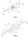
figures 1 and 2 are axonometric views of an device, according to an embodiment, when in an transport configuration and when in an operative configuration, respectively; -
figure 3 is a perspective view of a paddle, according to an embodiment; -
figure 4 is a perspective view of a lead, according to an embodiment; -
figure 5 is a perspective view of a device comprising the paddle offigure 3 and the lead offigure 4 ; -
figure 6 shows a cross-section of a kit comprising a device, according to an embodiment, and a portion of a delivery system; -
figure 7 is an axonometric view of a kit comprising a device, according to an embodiment, and a portion of delivery system; -
figures 8 and 9 show perspective views of a biasing device, according to some embodiments; -
figure 10 shows a perspective view of a device, according to an embodiment; -
figure 11 shows a perspective view of a device, according to an embodiment; -
figure 12 shows an elevation view of a lead of an implantable electrode assembly, according to an embodiment; -
figures 13 and 14 shows an elevation view of an assembly, according to some embodiments, comprising a portion of lead and a control device; -
figure 15 shows diagrammatically a target living anatomy; -
figure 16 shows aa device, according to an embodiment, during implantation in the target living anatomy offigure 15 ; -
figure 17 shows diagrammatically an assembly comprising a device, according to an embodiment, when implanted in a target living anatomy; -
figure 18 shows a perspective view of a device, according to an embodiment. - . According to a general embodiment, a
device 1 comprises at least onelead 2 and at least onepaddle 5. - .
Said device 1 is suitable for application in electrotherapy. - .
Said device 1 is suitable for application in electrophysiology. - . Preferably, said
device 1 is animplantable device 1. Preferably, the term "implantable" means that thedevice 1 is designed to be implanted long term, preferably permanently, within a livinganatomy 10 inside apatient body 11. Preferably, the term "implantable" also means that thedevice 1 is designed to be implanted temporary for example during surgery within a livinganatomy 10 inside apatient body 11. - . A
device 1 according to the present invention is suitable for electrotherapy applications such as: pain reduction, implanted muscle stimulation, treatment of neuromuscular dysfunctions, tissue repair, treatment of urine and fecal incontinence, treatment of masculine erectile dysfunctions, treatment of edema, lymphatic drainage, peripheral nerve stimulation. Theimplantable electrode assembly 1 according to the present invention is particularly suitable for, although not univocally intended to, spinal cord stimulation. - . A
device 1 according to the present invention is suitable for electrophysiology applications such as: peripheral nerve recording, cardiac wall recording, electro-corticography, electroencephalography, electromyography. - . A
device 1 according to the present invention is also suitable for intra-operatory procedures, to support surgery. - . Said at least one
lead 2 has an elongated lead body extending along a longitudinal direction X-X and comprising aproximal end 3 and adistal end 4. - . According to an embodiment, said longitudinal direction X-X is coincident with the axis of longitudinal development of the
lead 2 elongated body. - . According to an embodiment, a transversal direction Y-Y is defined orthogonal to said longitudinal direction X-X.
- . According to an embodiment, a cylindrical set of coordinates is defined, comprising said longitudinal direction X-X, a radial direction Y-Y orthogonal to said longitudinal direction and incident with said longitudinal direction X-X, and a circumferential direction, orthogonal both to said longitudinal direction X-X and to said radial direction Y-Y.
- . According to an embodiment, at least the
distal end 4 of thelead 2 comprises a substantially cylindrical body, preferably having a rounded cross-section around said longitudinal direction X-X. - . According to an embodiment, at least the
distal end 4 of thelead 2 is tapered, to reduce the transversal or radial encumber or extension of thedevice 1. - . According to an embodiment, the
proximal end 3 of thelead 2 compriseselectrical contacts 35 for electrically connect with acontrol device 36. For example, saidcontrol device 36 comprises a pulse generator. - . Said at least one
paddle 5 has a paddle body comprising two oppositemajor surfaces paddle thickness 33 there between. Preferably, said two oppositemajor surfaces paddle 5 face opposite one another. Preferably, each of said two oppositemajor surfaces paddle 5 comprises a major surfacelongitudinal size 31 extending along said longitudinal direction X-X and amajor surface width 32 transversal to said major surfacelongitudinal size 31. Preferably, thepaddle thickness 33 is a fraction of each the major surfacelongitudinal size 31 and/orwidth 32. For example, thepaddle 5 is in form of a film or the like. - . Said
paddle 5 comprises at least onepaddle electrode 8 having an exposedsurface 9 designed to come into electrical contact with a livinganatomy 10 inside a patient'sbody 11. For example, said living anatomy may comprise a living tissue and/or organ and/or a body fluid. - . Thanks to the provision of said at least one
electrode 8 saiddevice 1 may provide electrical stimulation to said livinganatomy 10. - . Thanks to the provision of said at least one
electrode 8 saiddevice 1 may record electrical activity of a livinganatomy 10. - . Said exposed
surface 9 of the at least oneelectrode 8 acts as electrical termination of thedevice 1. - . According to an embodiment, said at least one
paddle electrode 8 comprises a exposedsurface 9 that functionally emerges from said firstmajor surface 6 of thepaddle 5. In other words, said exposedsurface 9 of said at least oneelectrode 8 forms together with said firstmajor surface 6 of thepaddle body 5 the outer surface of thepaddle 5, that is to say the boundary of thepaddle 5 volume. - . The terminology "exposed
surface 9 that functionally emerges from said firstmajor surface 6" means that thepaddle 5 exhibits said exposedsurface 9 of thepaddle electrode 8, and the exposedsurface 9 does not necessarily protrude from the firstmajor surface 6, although according to an embodiment the exposedsurface 9 does protrude from said firstmajor surface 6. - . According to an embodiment, the terminology "exposed
surface 9 that functionally emerges from said firstmajor surface 6" indicates also the case wherein said at least oneelectrode 8 covers the entire firstmajor surface 6 of thepaddle 5 forming an exposedsurface 9, as well as the case wherein said at least oneelectrode 8 covers the entire firstmajor surface 6 of a paddle half-body, for example apaddle wing 21. - . Said
paddle 5 is suitable to modify thetransverse encumber 12 thereof, so that to assume at least one transport configuration and at least one operative configuration, wherein thetransverse encumber 12 of thepaddle 5 when in said at least one transport configuration is less than thetransverse encumber 12 of thesame paddle 5 when in said at least one operative configuration. In other words, theradial encumber 12 of thepaddle 5 when in said at least one transport configuration is less than theradial encumber 12 of thesame paddle 5 when in said at least one operative configuration. - . The terminology "
transverse encumber 12" preferably refers to the "transverse extension 12" as well as the terminology "radial encumber" refers to the "radial extension". Thereby, thepaddle 5 is suitable to modify the transverse extension thereof to assume said at least one transport configuration and said at least one operative configuration. Not necessary thetransverse extension 12 of thepaddle 5 varies by transverse elongation of thepaddle wings 21 although according to an embodiment it may be the case. For example, thetransverse extension 12 varies as effect of folding/unfolding of thepaddle wings 21. - . Such a paddle extension may vary because one or more portions of the paddle may be folded and unfolded. In other words, the transverse or radial extension of the paddle may vary as consequence of folding and unfolding part of the paddle.
- . According to an embodiment, said
paddle 5 is deployable. - . According to an embodiment, said
paddle 5 is self-expansible. - . According to an embodiment, said
paddle 5 is self-expanding. - . Said
lead 2 comprises aconnection portion 13 near thedistal end 4 thereof. - . Preferably, said
connection portion 13 of thelead 2 is unsuitable to modify the transverse encumber thereof. In this way, saidconnection portion 13 of thelead 2 is substantially rigid in the radial direction and unsuitable to reduce its radial dimension under an external loading action. - . According to an embodiment, said
connection portion 13 of thelead 2 radially delimiting alongitudinal cavity 18 for hosting a guiding stylet. In this way, the elongated body of at least the portion near thedistal end 4 of thelead 2 is longitudinally hollow. Preferably, thedistal end 4 of thelead 2 longitudinally closes saidlongitudinal cavity 18. The provision of saidlongitudinal cavity 18 for receiving a steerable stylet improves the manoeuvrability of thedevice 1 inside thepatient body 11. - . Advantageously, said
connection portion 13 of thelead 2 comprises at least one arched electricallyconductive surface 14. According to a preferred embodiment, saidconnection portion 13 of thelead 2 comprises electricallyinsulant portions 57 comprising each at least one electrically insulant surface in between of two subsequent archedconductive surfaces 14 of the of theconnection portion 13 of thelead 2. - . With further advantage, said
paddle 5 comprises at least onecounter-connection portion 15 comprising at least one arched electricallyconductive counter-surface 16 in direct contact with said at least oneconductive surface 14 of theconnection portion 13 of thelead 2, so that said at least onecounter-connection portion 15 of thepaddle 5 has a transversally arched shape defining a first concavity R1 facing towards saidconnection portion 13 of thelead 2. - . Said at least one
conductive counter-surface 16 of thepaddle 5 is in electric communication with saidpaddle electrode 8 through at least oneconductive track 17 extending within the body ofpaddle 5 in such way that saidproximal end 3 of thelead 2 is in electrical communication with said exposedsurface 9 of the at least onepaddle electrode 8. - . The provision of
such connection portion 13 of thelead 2 and saidcounter-connection portion 15 of thepaddle 5 it is possible to have a larger electrically conductive contact surface area betweenpaddle 5 and lead 2 with respect to known solutions. - . Thanks to such a
device 1, it is possible to provide localized and directional stimulation to a livinganatomy 10 and at the same time it is possible to deliver thedevice 1 percutaneously inside apatient body 11, by means a mininavasive surgery. - . Moreover, thanks to such a
device 1, it is possible to provide localized and directional recording of the electrical activity of a livinganatomy 10 and at the same time it is possible to deliver thedevice 1 percutaneously inside apatient body 11, by means a mininavasive surgery. - . Preferably, thanks to said connection portion of the lead cooperating to said counter-connection portion of the paddle, no welding points are required between paddle and lead, without for this reason weakening the adhesion, thus reducing the radial or transversal encumber of the
device 1 when in transport configuration. - . According to a preferred embodiment, said
connection portion 13 of thelead 2 also forms a mechanical connection with saidcounter-connection portion 15 of thepaddle 5. In this way, saidconnection portion 13 of thelead 2 also forms an electrical and mechanical connection with saidcounter-connection portion 15 of thepaddle 5. - . According to an embodiment, fixing means 37, 38 are provided mechanically connecting said
connection portion 13 of thelead 2 and saidcounter-connection portion 15 of thepaddle 5. - . According to an embodiment,
glue 37 is provided mechanically connecting saidconnection portion 13 of thelead 2 and saidcounter-connection portion 15 of thepaddle 5. Preferably, saidglue 37 is electrically insulant. Preferably, saidglue 37 is placed between electrically insulant surfaces. - . According to an embodiment, a plurality of
clips 38 is provided mechanically connecting saidconnection portion 13 of thelead 2 and saidcounter-connection portion 15 of thepaddle 5. - . According to a preferred embodiment, said plurality of
clips 38 apply compressive force on the electrically conductive surface to create electrical contact. - . According to a preferred embodiment, said
connection portion 13 of thelead 2 has a cylindrical shape and saidcounter-connection portion 15 of thepaddle 5 embraces at least a portion of saidcylindrical connection portion 13 of thelead 2. In this way, a cross-section of thedevice 1, taken in a plane orthogonal to said longitudinal direction X-X, comprises arounded connection portion 13 of thelead 2 embraced for a predetermined first angular portion by saidcounter-connection portion 15 of thepaddle 5. Preferably, a second angular portion of said cross-section of theconnection portion 13 of thelead 2 is free from contact with saidpaddle 5. According to an embodiment,glue 37 is provided around said second angular portion of theconnection portion 13 of thelead 2. - . According to a preferred embodiment, said
paddle 5 comprises at least onepaddle fold 19 defining at least one transversally foldedportion 20 of thepaddle 5 comprising said at least onepaddle fold 19. Preferably, said at least one transversally foldedportion 20 of thepaddle 5 is disjoined from saidarched counter-connection portion 15 of thesame paddle 5. In this way, thepaddle 5 comprises at least two different arched portions. - . According to a preferred embodiment, said at least one transversally folded
portion 20 of thepaddle 5 defines a second concavity R2 opposite to said first concavity R1. In this way, a change of concavity is defined along the body of thepaddle 5. In this way, thepaddle 5 comprises at least oneflex 39 in between said at least onepaddle fold 19 and said at least onearched connection portion 15 of thepaddle 5. - . According to a preferred embodiment, said
paddle 5 comprises at least one paddletransversal edge 22 delimiting the width of saidmajor surfaces paddle fold 19 is located between saidcounter-connection portion 15 and saidtransversal edge 22 of thepaddle 5, defining apaddle wing 21 comprising afree end 23 and at least a portion of said at least onepaddle electrode 8. Preferably, saidpaddle wing 21 is wider than saidcounter-connection portion 15 of thepaddle 5. - . According to a preferred embodiment, said at least one
paddle fold 19 defining at least one transversally foldedportion 20 of thepaddle 5 is provided both when thepaddle 5 is in the transport configuration and when thepaddle 5 is in the operative configuration. - . According to a preferred embodiment, said
paddle 5 comprises two opposite paddle folds 19 opposite with respect to saidcounter-connection portion 15 of thepaddle 5 defining at least twoopposite paddle wings 21 each having afree end 23. - . According to an embodiment, when in said at least one
paddle wing 21 is able to change its orientation in respect of saidlead 2, in order to bring said exposedsurface 9 of said at least onepaddle electrode 8 at various distances from thelead 2. Furthermore, said at least onepaddle wing 21 able to change its orientation in respect of saidlead 2, allows to align the exposedsurface 9 of the atleast paddle electrode 8 to lean against a target anatomic part. - . Preferably, said at least one
paddle wing 21 is flexible at least in the transverse direction, so that is able to adhere against a curved target anatomic part. - . Preferably, when in transport configuration, said at least two
opposite paddle wings 21 are folded in such way that afirst portion 41 of one of saidmajor surfaces paddle 5 faces in the transversal or radial direction asecond portion 42 of the samemajor surface paddle 5. - . When the
wings 21 of thepaddle 5 are exactly in number of two and opposite with respect of saidcounter-connection portion 15 of thepaddle 5, the cross-section of thedevice 1 assume a "omega"-like shape, in other words a "Q"-like shape, where thewings 21 are the flat segment of the omega and thecounter-connection portion 15 of thepaddle 5 is the arched bridge of the omega. - . According to an embodiment, said at least one
paddle wing 21 comprises an array ofpaddle electrodes 8. Said array ofpaddle electrodes 8 may be unipolar or bipolar. Thepaddle electrodes 8 of said array ofpaddle electrodes 8 may be arranged substantially aligned along the longitudinal direction X-X and/or may be arranged offset one another. - . According to a preferred embodiment, said
device 1 comprises at least onebiasing device 24 biasing saidpaddle 5 towards said operative configuration. In this way, said at least onebiasing device 24 exerts a biasing action onto saidpaddle 5 towards the operative configuration. - . Not necessarily said biasing action is an elastic biasing action, although according to a preferred embodiment it is.
- . Preferably, said biasing
device 24 comprises at least oneelongated element 43 forming a closed path, saidelongated element 43 being arranged near the transversal edges of thepaddle 5. Preferably, saidelongated element 43 extends along thefree edge 23 of thepaddle wing 21. According to an embodiment, saidelongated element 43 delimits at least one throughhole 44. According to an embodiment, said biasingdevice 24 comprises one ormore stiffening elements 45 connected to said at least oneelongated element 43. Preferably, said one ormore stiffening elements 45 are beams extending transversally. - . According to an embodiment, said at least one
biasing device 24 comprises at least one elastic element and/or a super-elastic material. - . Preferably, the terminology "pseudo-elastic" and "super-elastic" refer to "pseudo-elasticity" and "super-elasticity", which in turn refer to elastic reversible response caused by a phase transformation between the austenitic and martensitic phases. Preferably, "pseudo-elasticity" and "super-elasticity" are substantially isotherm processes.
- . The term "elastic device" used herein also encompasses elements having pseudo-elastic or super-elastic behavior.
- . The stiffness of the elastic device can be chosen in order to overcome the resistance of the living tissue inside the patient body.
- . According to an embodiment, said at least one
biasing device 24 comprises at least one wire spring. - . According to an embodiment, said at least one
biasing device 24 comprises at least one leaf spring. - . According to an embodiment, said at least one
biasing device 24 comprises at least one coil spring. - . According to an embodiment, said at least one
biasing device 24 comprises at least one shape memory element made of a shape memory material. For example, said shape memory material comprise nitinol. - . The terminology "shape-memory material" refers to a material, for example an alloy, that remembers its pre-deformed shape and that when deformed returns to its pre-deformed shape when subject to a heat stress, for example heating, and it is not an isotherm process.
- . According to an embodiment, said at least one
biasing device 24 comprises an elastic device and a shape memory material. - . Preferably, said at least one
biasing device 24 is embedded within the body ofpaddle 5. In this way the biasingdevice 24 is between themajor surfaces - . According to an embodiment, an
envelope 40 is provided wrapping at least a portion of thepaddle 5. Preferably, saidenvelope 40 wraps also a portion of theconnection portion 13 of thelead 2. According to an embodiment, saidenvelope 40 forms aprotective abutment portion 46 for the at least onepaddle electrode 8 when in the transport configuration, so that the at least onepaddle electrode 8 is recessed in respect of saidprotective abutment portion 46 of theenvelope 40. - . According to a preferred embodiment, said
paddle 5 has a multi-layered structure comprising a plurality of layers. For example, said plurality of layers comprises: saidconductive track 17 and/said at least onepaddle electrode 8, apolymeric substrate 25 orcarrier 25, and preferably saidenvelope 40. - . According to a preferred embodiment, said
paddle 5 is in form of a multilayered thin film. - . According to a preferred embodiment, said
paddle 5 is made of aflexible polymeric substrate 25 with embedded metal material forming said at least oneconductive track 17 and/or saidpaddle electrode 8. According to an embodiment, said embedded metal material is in form of a plurality of nanoparticles arranged in such way to form electrical connection with saidconductive surface 14 of thelead 2. In this way, the provision of saidpaddle fold 19 locally increases the electrically conductive capability of said conductive tracks 17. - . According to an embodiment, said embedded metal material is in form of a metal plate.
- . According to a general embodiment, it is provided an
assembly 51 comprising at least onedevice 1 according to any one of the embodiments described above, and at least onecontrol device 36. - . Preferably, said
control device 36 is associated to saidproximal end 3 of thelead 2, so that is in electrical communication with the exposedsurface 9 of the at least onepaddle electrode 8, through saidlead 2, saidarched connection surface 14 of the lead, saidconductive counter-surface 16 of thepaddle 5 and saidconductive track 17. - . According to an embodiment, said
control device 36 comprises at least onepulse generator 36. In this way, astimulator assembly 51 for electrotherapy is provided. The pulse generator may be implantable. - . According to an embodiment, said
control device 36 comprises at least amemory 36, for storing information about the electrical activity of aliving tissue 10. In this way, arecorder assembly 51 for electrophysiology is provided. The memory may be implantable. - . Preferably, said
control unit 36 comprises acase 55 and at least oneport 56 to receive theproximal end 3 of thelead 2. Anadapter 52 and a cabled connection to thecontrol unit 36 may be provided for connecting saidlead 2 with saidcontrol unit 36, for fitting the size of theproximal end 3 of thelead 2 with the size of theport 56. - . According to a general embodiment, it is provided a
kit 30 comprising at least onedevice 1 according to any one of the embodiments described above, and apercutaneous delivery system 27 comprising at least onehollow body 28. - . Advantageously, said
hollow body 28 houses said at least onedevice 1 when in transport configuration. - . According to an embodiment, said
hollow body 28 is a longitudinallyhollow body 28 defining a longitudinal cavity and comprising aproximal mouth 48 and adistal mouth 47. - . According to an embodiment, said
percutaneous delivery system 27 comprises asheath 49, and saidsheath 49 defines saidhollow body 28. - . According to an embodiment, said
percutaneous delivery system 27 comprises apercutaneous needle 50, and saidpercutaneous needle 50 defines saidhollow body 28. - . According to an embodiment, said
percutaneous delivery system 27 comprises also a guiding steerable stylet received inside thelongitudinal cavity 18 of thelead 2. Preferably, thedevice 1 comprises a distalfree end portion 58 free from contact with saidpaddle 5, saidfree end portion 58 delimiting a distal portion of saidlongitudinal cavity 18. In this way, the manoeuvrability of thedevice 1 is enhanced. - . According to an embodiment, said
percutaneous delivery system 27 comprises also a delivery catheter having a proximal end and a distal end, wherein thedevice 1 is near the distal end of the catheter. Preferably, the proximal end of the catheter is associated to a caterer handle designed to be hand held by a surgeon. - . According to a preferred embodiment, said at least one
paddle fold 19 defining a transversally foldedportion 20 of thepaddle 5 is contained inside thetransversal size 29 of thehollow body 28 of thepercutaneous delivery system 27. In this way, when thepaddle 5 is folded fits thesize 29 of thehollow body 28 of thepercutaneous delivery system 27. For example, thesize 29 of thehollow body 28 of thepercutaneous delivery system 27 is about 14G. - . According to a preferred embodiment, said
hollow body 28 acts as constraining body for thepaddle 5 constraining thepaddle 5 in the transport configuration. In this way, thepaddle 5 abuts against the hollow body. - . When the
paddle 5 is extracted from thedelivery system 27, for example by means of retraction of thesheath 49, thepaddle wings 21 modify their angular position with respect to saidlead 2, thus increasing the transverse orradial encumber 12 thereof.Void portions 59 may be provided inside the delivery system when thepaddle 5 is in transport configuration. - . According to a preferred embodiment as shown for example in
figures 15, 16 and 17 , and with particular reference to spinal cord stimulation applications, saiddevice 1 comprising apaddle 5 as described above, allows for percutaneous implantation within theepidural space 53 of atarget living anatomy 10, preferably a humantarget living anatomy 10, without for that reason limiting the maximum transversal size of thepaddle 5. Therefore, it is possible to apply localized and directional electrical stimulation to thespinal cord 54, thanks to a suitably designed disposition of theelectrodes 8 and the orientation of thepaddle wings 21, and at the same time the implantation is achieved through mininvasive surgery. - . A method of percutaneous implant of a
device 1 will be described in the following. - . The method of percutaneous implant comprises the steps of:
- providing a
device 1, according to any one of the embodiments described above; - transporting the
device 1 near atarget living anatomy 48; - delivering the
device 1 into atarget living anatomy 10 inside apatient body 11. - . The method of percutaneous implant comprises the step of unloading the
device 1. - . Preferably, this step is carried out by means of gradually longitudinally exit the
device 1 from thepercutaneous delivery system 27, in such way that a first portion of thepaddle 5 is already in the implant configuration while a second portion of thepaddle 5, is still in the transport configuration within anhollow body 28 of thedelivery system 27. - . Then, the method of percutaneous implant comprises the further step of increasing, preferably gradually increasing, the transverse or
radial encumber 12 of saiddevice 1. - . Thanks to the features described above, provided either separately or jointly in particular embodiments, it is possible to respond to the above-cited drawbacks and to provide the above-cited advantages, and in particular:
- it is provided an implantable paddle lead for electrotherapy and electrophysiology that allow minimally invasive procedure for implantation and/or for explantation;
- the interconnection between a thin stretchable polymer with embedded conductive stretchable metal lines and electrode with a cylindrical lead, allow to transform a multi-directional stimulation given by a cylindrical lead in a directional stimulation of a paddle electrode;
- the arched portions offer a stretched side and an opposite compressed side at the area of interconnection between paddle and lead;
- the provision of a "omega"-like shape when the paddle is in the transport configuration allows to save space during transport when compared to other configurations because it avoids to provide welding points and/or cables;
- the electrical connection of the cylindrical lead and metal lines is such that it allows a larger area of contact with respect of known solutions, which decreases resistance and decreases manufacturing challenges during assembly;
- therefore, a lower delivery sheath diameter over paddle width ratio is achieved in respect of known solutions;
- furthermore, the "omega"-like shape of the transport configuration of the paddle allows the folding of the paddle around a cylindrical lead, thus permitting the insertion in a catheter sheath that brings the paddle in the target position;
- the paddle may have eight electrode divided in two columns of four, or it can have more electrodes, for example two columns of eight, while can be introduced percutaneously;
- when in position the paddle is opened by the extraction of the sheath;
- the action needed to open the paddle may be given by an embedded spring within the paddle body;
- the cylindrical lead has a lumen dedicated to the stylet to allow insertion of straight or bended stylet to steer the catheter and the device inside the epidural space for spinal cord stimulation and/or recording;
- if the proximal lead end is smaller, to save space and keep needle dimension smaller, an adapter or a special cable with the two extremities with different dimension may be provided for;
- the provision of a needle with rounded edges at its distal mouth avoids to damage the lead and the paddle;
- it is possible to convert a cylindrical multi-directional lead electrode into a wide-area directional lead, having a compact design that minimize the volume of space needed for the interconnection of the lead to the paddle electrodes;
- it is provided a paddle having a flat part that can be folded around the cylindrical lead, to save space for the insertion through minimally invasive tools like catheters, sheaths and/or cannula devices;
- folding and unfolding the paddle has an effect on the transverse extension of the device;
- connecting means are provided in order to electrically and mechanically couple the paddle electrode to the lead of the device.
- . Those skilled in art may make many changes and adaptations to the embodiments described above or may replace elements with others that are functionally equivalent in order to satisfy contingent needs without however departing from the scope of the invention, which is defined by the appended claims.
LIST OF REFERENCES 1 Device 2 Lead 3 Proximal end of the lead 4 Distal end of the lead 5 Paddle 6 First major surface of the paddle 7 Second major surface of the paddle 8 Paddle electrode 9 Exposed surface of the paddle electrode 10 Living anatomy 11 Patient body 12 Transversal or radial encumber, or extension 13 Connection portion of the lead 14 Arched conductive surface of the connection portion of the lead 15 Counter-connection portion of the paddle 16 Conductive counter surface of the paddle 17 Conductive track 18 Longitudinal cavity 19 Paddle fold 20 Folded portion of the paddle 21 Paddle wing, or wing 22 Transversal edge of the paddle 23 Free end of the wing 24 Biasing device 25 Polymeric substrate 27 Percutaneous delivery system 28 Hollow body 29 Cavity size 30 Kit 31 Longitudinal size of the paddle 32 Width of the paddle 33 Thickness of the paddle 35 Electrical contacts of the proximal end of the lead 36 Control unit 37 Glue 38 Clip 39 Flex 40 Envelope 41 First portion of the major surface 42 Second portion of the major surface 43 Elongated element of the biasing device 44 Hole or window of the biasing device 45 Stiffering element of the biasing device 46 Protective abutment portion 47 Distal mouth of the delivery system 48 Proximal mouth of the delivery system 49 Sheath 50 Needle 51 Assembly 52 Adapter 53 Epidural space 54 Spinal cord 55 Case of the control unit 56 Port of the control unit 57 Electrically insulant portion of the of the connection portion of the lead 58 Distal free end of the device 59 Void portion R1 First concavity R2 Second concavity X-X Longitudinal direction Y-Y Transversal direction or radial direction
Claims (13)
- Device (1) for electrotherapy and/or electrophysiology comprising:- at least one lead (2) having an elongated lead body extending along a longitudinal direction (X-X) and comprising a proximal end (3) and a distal end (4); and- at least one paddle (5) having a paddle body comprising two opposite major surfaces (6, 7) defining a paddle thickness (33) there between;and wherein:- said paddle (5) comprising at least one paddle electrode (8) having an exposed surface (9) designed to come into electrical contact with a living anatomy (10) inside a patient's body (11);- said paddle (5) is suitable to modify the transverse extension (12) thereof, so that to assume at least one transport configuration and at least one operative configuration, wherein the transverse extension (12) of the paddle (5) when in said at least one transport configuration is less than the transverse extension (12) of the same paddle (5) when in said at least one operative configuration; and wherein:- said lead (2) comprising a connection portion (13) near the distal end (4) thereof;
characterised in that- said connection portion (13) of the lead (2) comprises at least one arched electrically conductive surface (14); and- said paddle (5) comprises at least one counter-connection portion (15) comprising at least one arched electrically conductive counter-surface (16) in direct contact with said at least one conductive surface (14) of the connection portion (13) of the lead (2), so that said at least one counter-connection portion (15) of the paddle (5) has a transversally arched shape defining a first concavity (R1) facing towards said connection portion (13) of the lead (2);- said at least one conductive counter-surface (16) of the paddle (5) is in electric communication with said paddle electrode (8) through at least one conductive track (17) extending within the body of paddle (5) in such way that said proximal end (3) of the lead (2) is in electrical communication with said exposed surface (9) of the at least one paddle electrode (8). - Device (1) according to claim 1, wherein said paddle (5) comprises at least one paddle fold (19) defining at least one transversally folded portion (20) of the paddle (5) comprising said at least one paddle fold (19).
- Device (1) according to claim 1 or 2, wherein said at least one transversally folded portion (20) of the paddle (5) defines a second concavity (R2) opposite to said first concavity (R1).
- Device (1) according to any one of the preceding claims, wherein said paddle (5) comprises at least one paddle transversal edge (22) delimiting the width of said major surfaces (6, 7), and wherein said at least one paddle fold (19) is located between said counter-connection portion (15) and said transversal edge (22) of the paddle (5), defining a paddle wing (21) comprising a free end (23) and at least a portion of said at least one paddle electrode (8).
- Device (1) according any one of the preceding claims, wherein said at least one paddle fold (19) defining at least one transversally folded portion (20) of the paddle (5) is provided both when the paddle (5) is in the transport configuration and when the paddle (5) is in the operative configuration.
- Device (1) according any one of the preceding claims, wherein said paddle (5) comprises two opposite paddle folds (19) opposite with respect to said counter-connection portion (15) of the paddle (5) defining at least two opposite paddle wings (21) each having a free end.
- Device (1) according any one of the preceding claims, comprising at least one biasing device (24) biasing said paddle (5) towards said operative configuration; and/or wherein- said at least one biasing device (24) comprises at least one elastic element, made of elastic and/or a super-elastic material; and/or wherein- said at least one biasing device (24) comprises at least one shape memory element made of a shape memory material; and/or wherein- said at least one biasing device (24) is embedded within the paddle (5).
- Device (1) according any one of the preceding claims, wherein said paddle (5) has a multi-layered structure; and/or wherein- said paddle (5) is made of a polymeric substrate (25) with embedded and/or deposited thin film of metal material forming said at least one conductive track (17) and/or said paddle electrode (8); and/or wherein- said embedded metal material is in form of a plurality of nanoparticles arranged in such way to form electrical connection with said conductive surface (14) of the lead (2); and/or wherein- said embedded metal material is in form of a metal plate.
- Device (1) according any one of the preceding claims, comprising a distal free end portion (58) free from contact with said paddle (5), said free end portion (58) delimiting a distal portion of said longitudinal cavity (18) a longitudinal cavity (18) for hosting a guiding stylet.
- Kit (30) comprising at least one device (1) according to any one of the preceding claims and a percutaneous delivery system (27) comprising at least one hollow body (28), wherein said hollow body (28) houses said at least one device (1) when in transport configuration.
- Kit (30) according to claim 10, wherein said at least one fold defining a transversally folded segment of the paddle is contained inside the transversal size (29) of the hollow body (28) of the percutaneous delivery system (27).
- Kit (30) according to claim 10 or 11, wherein said hollow body (28) acts as constraining body for the paddle (5) constraining the paddle (5) in the transport configuration.
- Assembly (51) comprising at least one device (1) according to any one of claims 1 to 9 and at least one control unit (36), wherein said assembly (51) is an stimulator for electrotherapy and/or a recorder for electrophysiology.
Applications Claiming Priority (2)
| Application Number | Priority Date | Filing Date | Title |
|---|---|---|---|
| IT102019000005268A IT201900005268A1 (en) | 2019-04-05 | 2019-04-05 | Device for electrotherapy and / or electrophysiology, kit and assembly |
| PCT/EP2020/059047 WO2020201252A1 (en) | 2019-04-05 | 2020-03-31 | Device for electrotherapy and/or electrophysiology, kit and assembly |
Publications (2)
| Publication Number | Publication Date |
|---|---|
| EP3927418A1 EP3927418A1 (en) | 2021-12-29 |
| EP3927418B1 true EP3927418B1 (en) | 2022-06-22 |
Family
ID=67108105
Family Applications (1)
| Application Number | Title | Priority Date | Filing Date |
|---|---|---|---|
| EP20713681.3A Active EP3927418B1 (en) | 2019-04-05 | 2020-03-31 | Device for electrotherapy and/or electrophysiology, kit and assembly |
Country Status (13)
| Country | Link |
|---|---|
| US (1) | US11446484B2 (en) |
| EP (1) | EP3927418B1 (en) |
| JP (1) | JP7087209B2 (en) |
| KR (1) | KR102451699B1 (en) |
| CN (1) | CN113677391B (en) |
| CA (1) | CA3131317C (en) |
| DK (1) | DK3927418T3 (en) |
| ES (1) | ES2927132T3 (en) |
| IL (1) | IL286996B2 (en) |
| IT (1) | IT201900005268A1 (en) |
| MX (1) | MX395451B (en) |
| PL (1) | PL3927418T3 (en) |
| WO (1) | WO2020201252A1 (en) |
Families Citing this family (6)
| Publication number | Priority date | Publication date | Assignee | Title |
|---|---|---|---|---|
| EP3821940B1 (en) * | 2019-11-13 | 2025-01-01 | BIOTRONIK SE & Co. KG | Electrode contact, electrode lead comprising an electrode contact and method for connecting an electrode contact to an electrical lead |
| WO2021257397A1 (en) * | 2020-06-18 | 2021-12-23 | St. Jude Medical, Cardiology Division, Inc. | Device and method for delivering electroporation therapy |
| US20230211152A1 (en) | 2022-01-05 | 2023-07-06 | Wise Srl | Device and method for electrotherapy and/or electrophysiology |
| US20250135195A1 (en) * | 2022-02-17 | 2025-05-01 | Biotronik Se & Co. Kg | Paddle lead |
| EP4321205A1 (en) * | 2022-08-12 | 2024-02-14 | INBRAIN Neuroelectronics SL | Protective casing for a thin-film lead paddle |
| US20240424288A1 (en) * | 2023-06-26 | 2024-12-26 | Micro-Leads, Inc. | Injectable self-expanding electrodes with discontinuous elements |
Citations (2)
| Publication number | Priority date | Publication date | Assignee | Title |
|---|---|---|---|---|
| US20020151948A1 (en) * | 1998-04-30 | 2002-10-17 | Medtronic, Inc. | Apparatus and method for expanding a simulation lead body in situ |
| US20120143296A1 (en) * | 2010-12-03 | 2012-06-07 | Boston Scientific Neuromodulation Corporation | Percutaneously implantable paddle-type lead and methods and devices for deployment |
Family Cites Families (24)
| Publication number | Priority date | Publication date | Assignee | Title |
|---|---|---|---|---|
| US6934956B1 (en) | 1997-09-09 | 2005-08-23 | Micron Technology, Inc. | Method and apparatus for installing an operating system |
| US6522932B1 (en) | 1998-02-10 | 2003-02-18 | Advanced Bionics Corporation | Implantable, expandable, multicontact electrodes and tools for use therewith |
| US6319241B1 (en) | 1998-04-30 | 2001-11-20 | Medtronic, Inc. | Techniques for positioning therapy delivery elements within a spinal cord or a brain |
| DE19936090A1 (en) | 1999-07-30 | 2001-02-01 | Fischer Artur Werke Gmbh | Metal fastener |
| JP3593963B2 (en) | 2000-08-29 | 2004-11-24 | セイコーエプソン株式会社 | Voltage controlled oscillator, IC chip for voltage controlled oscillator, resistance adjusting device and resistance adjusting method |
| US6593806B1 (en) | 2001-08-10 | 2003-07-15 | Cirrus Logic, Inc. | Circuits and methods for compensating switched mode amplifiers |
| US7177702B2 (en) * | 2004-03-12 | 2007-02-13 | Scimed Life Systems, Inc. | Collapsible/expandable electrode leads |
| US7769472B2 (en) | 2005-07-29 | 2010-08-03 | Medtronic, Inc. | Electrical stimulation lead with conformable array of electrodes |
| ATE428468T1 (en) | 2006-02-10 | 2009-05-15 | Advanced Neuromodulation Sys | SELF-FOLDING PADDLE-SHAPED PIPE AND METHOD FOR PRODUCING A PADDLE-SHAPED PIPE |
| US9314618B2 (en) | 2006-12-06 | 2016-04-19 | Spinal Modulation, Inc. | Implantable flexible circuit leads and methods of use |
| WO2008109105A2 (en) | 2007-03-06 | 2008-09-12 | Flagship Ventures | Methods and compositions for improved therapeutic effects with sirna |
| US9492655B2 (en) | 2008-04-25 | 2016-11-15 | Boston Scientific Neuromodulation Corporation | Stimulation system with percutaneously deliverable paddle lead and methods of making and using |
| JP5735924B2 (en) * | 2009-01-14 | 2015-06-17 | スパイナル・モデュレーション・インコーポレイテッドSpinal Modulation Inc. | Stimulation leads and delivery systems and methods of use |
| US8676346B2 (en) | 2009-07-24 | 2014-03-18 | Richard B. North | Electrode having erectable lead |
| IT1399202B1 (en) | 2010-03-30 | 2013-04-11 | Corbelli | METHOD FOR THE PRODUCTION OF FUNCTIONALIZED ELASTOMERIC ARTICLES AND MANUFACTURED ARTICLES |
| US8934956B2 (en) | 2010-08-31 | 2015-01-13 | Interventional Autonomics Corporation | Intravascular electrodes and anchoring devices for transvascular stimulation |
| WO2012166467A1 (en) | 2011-05-27 | 2012-12-06 | Stryker Corporation | Assembly for percutaneously inserting an implantable medical device, steering the device to a target location and deploying the device |
| KR101497458B1 (en) * | 2011-08-25 | 2015-03-02 | 코비디엔 엘피 | Systems, devices, and methods for treatment of luminal tissue |
| US20140343564A1 (en) | 2013-03-15 | 2014-11-20 | Advanced Neuromodulation Systems, Inc. dba St. Jude Neuromodulation Division | Paddle leads for neurostimulation and method of delivering the same |
| EP3013411A1 (en) * | 2013-06-27 | 2016-05-04 | Boston Scientific Neuromodulation Corporation | Paddle leads and lead arrangements for dorsal horn stimulation and systems using the leads |
| US9643003B2 (en) * | 2014-11-10 | 2017-05-09 | Steven Sounyoung Yu | Craniofacial neurostimulation for treatment of pain conditions |
| ITUA20163746A1 (en) | 2016-05-24 | 2017-11-24 | Wise S R L | ELECTRIC INTERCONNECTION SYSTEM BETWEEN AN INTRINSICALLY EXTENSIBLE CONDUCTOR AND A NON-INSTRUCTIVE EXTENSIBLE |
| WO2018136822A1 (en) * | 2017-01-19 | 2018-07-26 | Micro-Leads, Inc. | Spinal cord stimulation method to treat lateral neural tissues |
| WO2018227019A1 (en) * | 2017-06-07 | 2018-12-13 | Neuronexus Technologies, Inc. | Systems and methods for flexible electrode arrays |
-
2019
- 2019-04-05 IT IT102019000005268A patent/IT201900005268A1/en unknown
-
2020
- 2020-03-31 PL PL20713681.3T patent/PL3927418T3/en unknown
- 2020-03-31 KR KR1020217036022A patent/KR102451699B1/en active Active
- 2020-03-31 ES ES20713681T patent/ES2927132T3/en active Active
- 2020-03-31 JP JP2021559149A patent/JP7087209B2/en active Active
- 2020-03-31 CA CA3131317A patent/CA3131317C/en active Active
- 2020-03-31 EP EP20713681.3A patent/EP3927418B1/en active Active
- 2020-03-31 WO PCT/EP2020/059047 patent/WO2020201252A1/en not_active Ceased
- 2020-03-31 MX MX2021012118A patent/MX395451B/en unknown
- 2020-03-31 CN CN202080027224.5A patent/CN113677391B/en active Active
- 2020-03-31 DK DK20713681.3T patent/DK3927418T3/en active
- 2020-04-03 US US16/840,101 patent/US11446484B2/en active Active
-
2021
- 2021-10-05 IL IL286996A patent/IL286996B2/en unknown
Patent Citations (2)
| Publication number | Priority date | Publication date | Assignee | Title |
|---|---|---|---|---|
| US20020151948A1 (en) * | 1998-04-30 | 2002-10-17 | Medtronic, Inc. | Apparatus and method for expanding a simulation lead body in situ |
| US20120143296A1 (en) * | 2010-12-03 | 2012-06-07 | Boston Scientific Neuromodulation Corporation | Percutaneously implantable paddle-type lead and methods and devices for deployment |
Also Published As
| Publication number | Publication date |
|---|---|
| KR20210138118A (en) | 2021-11-18 |
| WO2020201252A1 (en) | 2020-10-08 |
| IL286996A (en) | 2021-12-01 |
| JP2022523876A (en) | 2022-04-26 |
| IL286996B2 (en) | 2023-02-01 |
| DK3927418T3 (en) | 2022-09-12 |
| ES2927132T3 (en) | 2022-11-02 |
| CA3131317A1 (en) | 2020-10-08 |
| JP7087209B2 (en) | 2022-06-20 |
| MX395451B (en) | 2025-03-25 |
| CA3131317C (en) | 2023-03-21 |
| KR102451699B1 (en) | 2022-10-06 |
| CN113677391A (en) | 2021-11-19 |
| IT201900005268A1 (en) | 2020-10-05 |
| IL286996B (en) | 2022-10-01 |
| US20200316371A1 (en) | 2020-10-08 |
| BR112021019981A2 (en) | 2021-12-07 |
| US11446484B2 (en) | 2022-09-20 |
| CN113677391B (en) | 2022-08-19 |
| PL3927418T3 (en) | 2022-12-12 |
| MX2021012118A (en) | 2022-09-08 |
| EP3927418A1 (en) | 2021-12-29 |
Similar Documents
| Publication | Publication Date | Title |
|---|---|---|
| US11446484B2 (en) | Device for electrotherapy and/or electrophysiology, kit and assembly | |
| US12324910B2 (en) | Visual prosthesis employing ventricular or endovascular neural electrode arrays | |
| US8801728B2 (en) | Introduction of medical lead into patient | |
| US9089693B2 (en) | Lead positioning and finned fixation system | |
| US11116966B2 (en) | Retention mechanism for an implantable lead | |
| EP1996283A2 (en) | Left ventricular lead shapes | |
| US12396838B2 (en) | Methods of transmitting neural activity | |
| US11219775B2 (en) | Retention mechanism for an implantable lead | |
| US20230211152A1 (en) | Device and method for electrotherapy and/or electrophysiology | |
| CN116209404A (en) | Implantable medical lead | |
| US11766571B2 (en) | Retention mechanism for an implantable lead | |
| BR112021019981B1 (en) | DEVICE FOR ELECTROTHERAPY AND/OR ELECTROPHYSIOLOGY, KIT AND SET |
Legal Events
| Date | Code | Title | Description |
|---|---|---|---|
| STAA | Information on the status of an ep patent application or granted ep patent |
Free format text: STATUS: UNKNOWN |
|
| STAA | Information on the status of an ep patent application or granted ep patent |
Free format text: STATUS: THE INTERNATIONAL PUBLICATION HAS BEEN MADE |
|
| PUAI | Public reference made under article 153(3) epc to a published international application that has entered the european phase |
Free format text: ORIGINAL CODE: 0009012 |
|
| STAA | Information on the status of an ep patent application or granted ep patent |
Free format text: STATUS: REQUEST FOR EXAMINATION WAS MADE |
|
| 17P | Request for examination filed |
Effective date: 20210921 |
|
| AK | Designated contracting states |
Kind code of ref document: A1 Designated state(s): AL AT BE BG CH CY CZ DE DK EE ES FI FR GB GR HR HU IE IS IT LI LT LU LV MC MK MT NL NO PL PT RO RS SE SI SK SM TR |
|
| GRAP | Despatch of communication of intention to grant a patent |
Free format text: ORIGINAL CODE: EPIDOSNIGR1 |
|
| STAA | Information on the status of an ep patent application or granted ep patent |
Free format text: STATUS: GRANT OF PATENT IS INTENDED |
|
| DAV | Request for validation of the european patent (deleted) | ||
| DAX | Request for extension of the european patent (deleted) | ||
| INTG | Intention to grant announced |
Effective date: 20220218 |
|
| RIC1 | Information provided on ipc code assigned before grant |
Ipc: A61N 1/36 20060101ALI20220207BHEP Ipc: A61N 1/05 20060101AFI20220207BHEP |
|
| GRAS | Grant fee paid |
Free format text: ORIGINAL CODE: EPIDOSNIGR3 |
|
| GRAA | (expected) grant |
Free format text: ORIGINAL CODE: 0009210 |
|
| STAA | Information on the status of an ep patent application or granted ep patent |
Free format text: STATUS: THE PATENT HAS BEEN GRANTED |
|
| AK | Designated contracting states |
Kind code of ref document: B1 Designated state(s): AL AT BE BG CH CY CZ DE DK EE ES FI FR GB GR HR HU IE IS IT LI LT LU LV MC MK MT NL NO PL PT RO RS SE SI SK SM TR |
|
| REG | Reference to a national code |
Ref country code: GB Ref legal event code: FG4D |
|
| REG | Reference to a national code |
Ref country code: CH Ref legal event code: EP |
|
| REG | Reference to a national code |
Ref country code: DE Ref legal event code: R096 Ref document number: 602020003682 Country of ref document: DE |
|
| REG | Reference to a national code |
Ref country code: AT Ref legal event code: REF Ref document number: 1499373 Country of ref document: AT Kind code of ref document: T Effective date: 20220715 |
|
| REG | Reference to a national code |
Ref country code: IE Ref legal event code: FG4D |
|
| REG | Reference to a national code |
Ref country code: DK Ref legal event code: T3 Effective date: 20220907 |
|
| REG | Reference to a national code |
Ref country code: NL Ref legal event code: FP |
|
| REG | Reference to a national code |
Ref country code: SE Ref legal event code: TRGR |
|
| REG | Reference to a national code |
Ref country code: LT Ref legal event code: MG9D |
|
| PG25 | Lapsed in a contracting state [announced via postgrant information from national office to epo] |
Ref country code: NO Free format text: LAPSE BECAUSE OF FAILURE TO SUBMIT A TRANSLATION OF THE DESCRIPTION OR TO PAY THE FEE WITHIN THE PRESCRIBED TIME-LIMIT Effective date: 20220922 Ref country code: LT Free format text: LAPSE BECAUSE OF FAILURE TO SUBMIT A TRANSLATION OF THE DESCRIPTION OR TO PAY THE FEE WITHIN THE PRESCRIBED TIME-LIMIT Effective date: 20220622 Ref country code: HR Free format text: LAPSE BECAUSE OF FAILURE TO SUBMIT A TRANSLATION OF THE DESCRIPTION OR TO PAY THE FEE WITHIN THE PRESCRIBED TIME-LIMIT Effective date: 20220622 Ref country code: GR Free format text: LAPSE BECAUSE OF FAILURE TO SUBMIT A TRANSLATION OF THE DESCRIPTION OR TO PAY THE FEE WITHIN THE PRESCRIBED TIME-LIMIT Effective date: 20220923 Ref country code: FI Free format text: LAPSE BECAUSE OF FAILURE TO SUBMIT A TRANSLATION OF THE DESCRIPTION OR TO PAY THE FEE WITHIN THE PRESCRIBED TIME-LIMIT Effective date: 20220622 Ref country code: BG Free format text: LAPSE BECAUSE OF FAILURE TO SUBMIT A TRANSLATION OF THE DESCRIPTION OR TO PAY THE FEE WITHIN THE PRESCRIBED TIME-LIMIT Effective date: 20220922 |
|
| REG | Reference to a national code |
Ref country code: ES Ref legal event code: FG2A Ref document number: 2927132 Country of ref document: ES Kind code of ref document: T3 Effective date: 20221102 |
|
| REG | Reference to a national code |
Ref country code: AT Ref legal event code: MK05 Ref document number: 1499373 Country of ref document: AT Kind code of ref document: T Effective date: 20220622 |
|
| PG25 | Lapsed in a contracting state [announced via postgrant information from national office to epo] |
Ref country code: RS Free format text: LAPSE BECAUSE OF FAILURE TO SUBMIT A TRANSLATION OF THE DESCRIPTION OR TO PAY THE FEE WITHIN THE PRESCRIBED TIME-LIMIT Effective date: 20220622 Ref country code: LV Free format text: LAPSE BECAUSE OF FAILURE TO SUBMIT A TRANSLATION OF THE DESCRIPTION OR TO PAY THE FEE WITHIN THE PRESCRIBED TIME-LIMIT Effective date: 20220622 |
|
| PG25 | Lapsed in a contracting state [announced via postgrant information from national office to epo] |
Ref country code: SM Free format text: LAPSE BECAUSE OF FAILURE TO SUBMIT A TRANSLATION OF THE DESCRIPTION OR TO PAY THE FEE WITHIN THE PRESCRIBED TIME-LIMIT Effective date: 20220622 Ref country code: SK Free format text: LAPSE BECAUSE OF FAILURE TO SUBMIT A TRANSLATION OF THE DESCRIPTION OR TO PAY THE FEE WITHIN THE PRESCRIBED TIME-LIMIT Effective date: 20220622 Ref country code: RO Free format text: LAPSE BECAUSE OF FAILURE TO SUBMIT A TRANSLATION OF THE DESCRIPTION OR TO PAY THE FEE WITHIN THE PRESCRIBED TIME-LIMIT Effective date: 20220622 Ref country code: PT Free format text: LAPSE BECAUSE OF FAILURE TO SUBMIT A TRANSLATION OF THE DESCRIPTION OR TO PAY THE FEE WITHIN THE PRESCRIBED TIME-LIMIT Effective date: 20221024 Ref country code: EE Free format text: LAPSE BECAUSE OF FAILURE TO SUBMIT A TRANSLATION OF THE DESCRIPTION OR TO PAY THE FEE WITHIN THE PRESCRIBED TIME-LIMIT Effective date: 20220622 Ref country code: CZ Free format text: LAPSE BECAUSE OF FAILURE TO SUBMIT A TRANSLATION OF THE DESCRIPTION OR TO PAY THE FEE WITHIN THE PRESCRIBED TIME-LIMIT Effective date: 20220622 Ref country code: AT Free format text: LAPSE BECAUSE OF FAILURE TO SUBMIT A TRANSLATION OF THE DESCRIPTION OR TO PAY THE FEE WITHIN THE PRESCRIBED TIME-LIMIT Effective date: 20220622 |
|
| PG25 | Lapsed in a contracting state [announced via postgrant information from national office to epo] |
Ref country code: IS Free format text: LAPSE BECAUSE OF FAILURE TO SUBMIT A TRANSLATION OF THE DESCRIPTION OR TO PAY THE FEE WITHIN THE PRESCRIBED TIME-LIMIT Effective date: 20221022 |
|
| REG | Reference to a national code |
Ref country code: DE Ref legal event code: R097 Ref document number: 602020003682 Country of ref document: DE |
|
| PG25 | Lapsed in a contracting state [announced via postgrant information from national office to epo] |
Ref country code: AL Free format text: LAPSE BECAUSE OF FAILURE TO SUBMIT A TRANSLATION OF THE DESCRIPTION OR TO PAY THE FEE WITHIN THE PRESCRIBED TIME-LIMIT Effective date: 20220622 |
|
| PLBE | No opposition filed within time limit |
Free format text: ORIGINAL CODE: 0009261 |
|
| STAA | Information on the status of an ep patent application or granted ep patent |
Free format text: STATUS: NO OPPOSITION FILED WITHIN TIME LIMIT |
|
| 26N | No opposition filed |
Effective date: 20230323 |
|
| P01 | Opt-out of the competence of the unified patent court (upc) registered |
Effective date: 20230524 |
|
| PG25 | Lapsed in a contracting state [announced via postgrant information from national office to epo] |
Ref country code: MC Free format text: LAPSE BECAUSE OF FAILURE TO SUBMIT A TRANSLATION OF THE DESCRIPTION OR TO PAY THE FEE WITHIN THE PRESCRIBED TIME-LIMIT Effective date: 20220622 |
|
| PG25 | Lapsed in a contracting state [announced via postgrant information from national office to epo] |
Ref country code: LU Free format text: LAPSE BECAUSE OF NON-PAYMENT OF DUE FEES Effective date: 20230331 |
|
| PG25 | Lapsed in a contracting state [announced via postgrant information from national office to epo] |
Ref country code: BG Free format text: LAPSE BECAUSE OF FAILURE TO SUBMIT A TRANSLATION OF THE DESCRIPTION OR TO PAY THE FEE WITHIN THE PRESCRIBED TIME-LIMIT Effective date: 20220622 |
|
| PG25 | Lapsed in a contracting state [announced via postgrant information from national office to epo] |
Ref country code: BG Free format text: LAPSE BECAUSE OF FAILURE TO SUBMIT A TRANSLATION OF THE DESCRIPTION OR TO PAY THE FEE WITHIN THE PRESCRIBED TIME-LIMIT Effective date: 20220622 |
|
| REG | Reference to a national code |
Ref country code: NL Ref legal event code: PD Owner name: WISE S.P.A.; IT Free format text: DETAILS ASSIGNMENT: CHANGE OF OWNER(S), CHANGE OF LEGAL ENTITY; FORMER OWNER NAME: WISE S.R.L. Effective date: 20250219 |
|
| REG | Reference to a national code |
Ref country code: DE Ref legal event code: R081 Ref document number: 602020003682 Country of ref document: DE Owner name: WISE S.P.A., COLOGNO MONZESE, IT Free format text: FORMER OWNER: WISE S.R.L., COLOGNO MONZESE, (MI), IT |
|
| REG | Reference to a national code |
Ref country code: ES Ref legal event code: PC2A Owner name: WISE S.P.A. Effective date: 20250523 |
|
| REG | Reference to a national code |
Ref country code: BE Ref legal event code: HC Owner name: WISE S.P.A; IT Free format text: DETAILS ASSIGNMENT: CHANGE OF OWNER(S), CHANGE OF OWNER(S) NAME; FORMER OWNER NAME: WISE S.R.L. Effective date: 20250220 |
|
| PGFP | Annual fee paid to national office [announced via postgrant information from national office to epo] |
Ref country code: ES Payment date: 20250402 Year of fee payment: 6 |
|
| PGFP | Annual fee paid to national office [announced via postgrant information from national office to epo] |
Ref country code: CH Payment date: 20250401 Year of fee payment: 6 |
|
| PG25 | Lapsed in a contracting state [announced via postgrant information from national office to epo] |
Ref country code: CY Free format text: LAPSE BECAUSE OF FAILURE TO SUBMIT A TRANSLATION OF THE DESCRIPTION OR TO PAY THE FEE WITHIN THE PRESCRIBED TIME-LIMIT; INVALID AB INITIO Effective date: 20200331 |
|
| PG25 | Lapsed in a contracting state [announced via postgrant information from national office to epo] |
Ref country code: HU Free format text: LAPSE BECAUSE OF FAILURE TO SUBMIT A TRANSLATION OF THE DESCRIPTION OR TO PAY THE FEE WITHIN THE PRESCRIBED TIME-LIMIT; INVALID AB INITIO Effective date: 20200331 |
|
| PG25 | Lapsed in a contracting state [announced via postgrant information from national office to epo] |
Ref country code: SI Free format text: LAPSE BECAUSE OF FAILURE TO SUBMIT A TRANSLATION OF THE DESCRIPTION OR TO PAY THE FEE WITHIN THE PRESCRIBED TIME-LIMIT Effective date: 20220622 |
|
| REG | Reference to a national code |
Ref country code: CH Ref legal event code: R18 Free format text: ST27 STATUS EVENT CODE: U-0-0-R10-R18 (AS PROVIDED BY THE NATIONAL OFFICE) Effective date: 20260217 |
|
| PGFP | Annual fee paid to national office [announced via postgrant information from national office to epo] |
Ref country code: NL Payment date: 20260213 Year of fee payment: 7 |
|
| REG | Reference to a national code |
Ref country code: CH Ref legal event code: U11 Free format text: ST27 STATUS EVENT CODE: U-0-0-U10-U11 (AS PROVIDED BY THE NATIONAL OFFICE) Effective date: 20260401 |
|
| PGFP | Annual fee paid to national office [announced via postgrant information from national office to epo] |
Ref country code: SE Payment date: 20260211 Year of fee payment: 7 |
|
| REG | Reference to a national code |
Ref country code: CH Ref legal event code: R17 Free format text: ST27 STATUS EVENT CODE: U-0-0-R10-R17 (AS PROVIDED BY THE NATIONAL OFFICE) Effective date: 20260408 |
|
| PGFP | Annual fee paid to national office [announced via postgrant information from national office to epo] |
Ref country code: GB Payment date: 20260209 Year of fee payment: 7 |
|
| PGFP | Annual fee paid to national office [announced via postgrant information from national office to epo] |
Ref country code: DE Payment date: 20260204 Year of fee payment: 7 Ref country code: DK Payment date: 20260313 Year of fee payment: 7 Ref country code: IE Payment date: 20260211 Year of fee payment: 7 |
|
| PGFP | Annual fee paid to national office [announced via postgrant information from national office to epo] |
Ref country code: BE Payment date: 20260216 Year of fee payment: 7 Ref country code: IT Payment date: 20260225 Year of fee payment: 7 |
|
| PGFP | Annual fee paid to national office [announced via postgrant information from national office to epo] |
Ref country code: FR Payment date: 20260209 Year of fee payment: 7 |
|
| PGFP | Annual fee paid to national office [announced via postgrant information from national office to epo] |
Ref country code: TR Payment date: 20260327 Year of fee payment: 7 |
|
| PGFP | Annual fee paid to national office [announced via postgrant information from national office to epo] |
Ref country code: PL Payment date: 20260123 Year of fee payment: 7 |