EP3927288B1 - Artificial wrist - Google Patents
Artificial wrist Download PDFInfo
- Publication number
- EP3927288B1 EP3927288B1 EP19716987.3A EP19716987A EP3927288B1 EP 3927288 B1 EP3927288 B1 EP 3927288B1 EP 19716987 A EP19716987 A EP 19716987A EP 3927288 B1 EP3927288 B1 EP 3927288B1
- Authority
- EP
- European Patent Office
- Prior art keywords
- cable
- movable body
- rotation
- elastic means
- artificial wrist
- Prior art date
- Legal status (The legal status is an assumption and is not a legal conclusion. Google has not performed a legal analysis and makes no representation as to the accuracy of the status listed.)
- Active
Links
Images

Classifications
-
- A—HUMAN NECESSITIES
- A61—MEDICAL OR VETERINARY SCIENCE; HYGIENE
- A61F—FILTERS IMPLANTABLE INTO BLOOD VESSELS; PROSTHESES; DEVICES PROVIDING PATENCY TO, OR PREVENTING COLLAPSING OF, TUBULAR STRUCTURES OF THE BODY, e.g. STENTS; ORTHOPAEDIC, NURSING OR CONTRACEPTIVE DEVICES; FOMENTATION; TREATMENT OR PROTECTION OF EYES OR EARS; BANDAGES, DRESSINGS OR ABSORBENT PADS; FIRST-AID KITS
- A61F2/00—Filters implantable into blood vessels; Prostheses, i.e. artificial substitutes or replacements for parts of the body; Appliances for connecting them with the body; Devices providing patency to, or preventing collapsing of, tubular structures of the body, e.g. stents
- A61F2/50—Prostheses not implantable in the body
- A61F2/54—Artificial arms or hands or parts thereof
- A61F2/58—Elbows; Wrists ; Other joints; Hands
- A61F2/583—Hands; Wrist joints
- A61F2/585—Wrist joints
-
- A—HUMAN NECESSITIES
- A61—MEDICAL OR VETERINARY SCIENCE; HYGIENE
- A61F—FILTERS IMPLANTABLE INTO BLOOD VESSELS; PROSTHESES; DEVICES PROVIDING PATENCY TO, OR PREVENTING COLLAPSING OF, TUBULAR STRUCTURES OF THE BODY, e.g. STENTS; ORTHOPAEDIC, NURSING OR CONTRACEPTIVE DEVICES; FOMENTATION; TREATMENT OR PROTECTION OF EYES OR EARS; BANDAGES, DRESSINGS OR ABSORBENT PADS; FIRST-AID KITS
- A61F2/00—Filters implantable into blood vessels; Prostheses, i.e. artificial substitutes or replacements for parts of the body; Appliances for connecting them with the body; Devices providing patency to, or preventing collapsing of, tubular structures of the body, e.g. stents
- A61F2/50—Prostheses not implantable in the body
- A61F2002/5003—Prostheses not implantable in the body having damping means, e.g. shock absorbers
-
- A—HUMAN NECESSITIES
- A61—MEDICAL OR VETERINARY SCIENCE; HYGIENE
- A61F—FILTERS IMPLANTABLE INTO BLOOD VESSELS; PROSTHESES; DEVICES PROVIDING PATENCY TO, OR PREVENTING COLLAPSING OF, TUBULAR STRUCTURES OF THE BODY, e.g. STENTS; ORTHOPAEDIC, NURSING OR CONTRACEPTIVE DEVICES; FOMENTATION; TREATMENT OR PROTECTION OF EYES OR EARS; BANDAGES, DRESSINGS OR ABSORBENT PADS; FIRST-AID KITS
- A61F2/00—Filters implantable into blood vessels; Prostheses, i.e. artificial substitutes or replacements for parts of the body; Appliances for connecting them with the body; Devices providing patency to, or preventing collapsing of, tubular structures of the body, e.g. stents
- A61F2/50—Prostheses not implantable in the body
- A61F2002/5038—Hinged joint, e.g. with transverse axle restricting the movement
-
- A—HUMAN NECESSITIES
- A61—MEDICAL OR VETERINARY SCIENCE; HYGIENE
- A61F—FILTERS IMPLANTABLE INTO BLOOD VESSELS; PROSTHESES; DEVICES PROVIDING PATENCY TO, OR PREVENTING COLLAPSING OF, TUBULAR STRUCTURES OF THE BODY, e.g. STENTS; ORTHOPAEDIC, NURSING OR CONTRACEPTIVE DEVICES; FOMENTATION; TREATMENT OR PROTECTION OF EYES OR EARS; BANDAGES, DRESSINGS OR ABSORBENT PADS; FIRST-AID KITS
- A61F2/00—Filters implantable into blood vessels; Prostheses, i.e. artificial substitutes or replacements for parts of the body; Appliances for connecting them with the body; Devices providing patency to, or preventing collapsing of, tubular structures of the body, e.g. stents
- A61F2/50—Prostheses not implantable in the body
- A61F2/68—Operating or control means
- A61F2002/6854—Operating or control means for locking or unlocking a joint
Definitions
- the present invention relates to an artificial wrist of the type specified in the preamble of the first claim, as is also disclosed in US patent US 2007/0173955 A1 .
- the invention is suitable to be used to connect an end effector (preferably a robotic hand or other prosthetic device) to a support (such as a suitably prosthetic robotic arm), thereby allowing reciprocal movement of the end effector and the support.
- a support such as a suitably prosthetic robotic arm
- the artificial wrist is suitable for use in the industrial or preferably prosthetic field.
- known artificial wrists provide a base element bound to the support, an element which moves relative to the base element and binds to the prosthetic device; and a hinge defining an axis of rotation between the elements and therefore between the support and the device.
- the hinge consists of a cross-shaped body interposed between the base element and the movable element and provided with two pairs of arms perpendicular to each other and defining two axes of rotation for said elements; torsion springs, one for each arm, having one end integral with the base element and the other with the movable element, so as to oppose their reciprocal rotation.
- torsion springs one for each arm, having one end integral with the base element and the other with the movable element, so as to oppose their reciprocal rotation.
- the hinge of this wrist consists of a pin hinging the elements, a rack engaging the pinion so that rotation of the pinion causes translation of the rack, and springs between the rack and the base element working in opposition to the translation of the rack.
- the technical task underlying the present invention is to devise an artificial wrist, which is capable of substantially obviating at least some of the above-mentioned drawbacks.
- a major object of the invention is to obtain a low-weight and small-sized artificial wrist.
- Another major object of the invention is to provide an artificial wrist, which is low-cost and above all practical and comfortable to use.
- the measures, values, shapes and geometric references (such as perpendicularity and parallelism), when used with words like “about” or other similar terms such as “approximately” or “substantially”, are to be understood as except for measurement errors or inaccuracies due to production and/or manufacturing errors and, above all, except for a slight divergence from the value, measure, shape or geometric reference with which it is associated.
- these terms if associated with a value, preferably indicate a divergence of not more than 10% from said value.
- the artificial wrist according to the invention is indicated as a whole by the number 1.
- the end effector is preferably a prosthetic device, and specifically a robotic hand.
- the support is identifiable as a suitably prosthetic robotic arm or an amputated limb.
- the artificial wrist 1 comprises a static body 2 adapted to be bound to a support; a movable body 3 adapted to be bound to an end effector; and at least one junction block 4 between the static body 2 and the movable body 3 and defining an axis of rotation 4a between the static body 2 and the movable body 3.
- the wrist 1 comprises a single junction block 4 and therefore the bodies 2 and 3 can be moved relative to each other along a single axis of rotation 4a.
- the static body 2 defines a first, suitably barycentric longitudinal axis 2a.
- the first longitudinal axis 2a is perpendicular to the axis of rotation 4a and appropriately incident to said axis of rotation 4a.
- the static body 2 comprises first fastening means 21 for fastening the static body 2 to the support.
- the movable body 3 defines a second, suitably barycentric longitudinal axis 3a.
- the second longitudinal axis 3a is perpendicular to the axis of rotation 4a and appropriately incident to said axis of rotation 4a.
- the movable body 3 comprises second fastening means 31 for fastening the movable body 3 to the end effector.
- the fastening means 21 and 31 are known in the art.
- the junction block 4 comprises a hinge 41 defining the axis of rotation 4a.
- junction block 4 is suitable to allow and at the same time oppose rotation between the static body 2 and the movable body 3, suitably around the axis of rotation 4a.
- a rest position ( Figs. 1-2 ) in which the resulting torque on the bodies 2 and 3 is zero and therefore the bodies 2 and 3 remain stationary relative to each other; and at least one activation position ( Fig. 3 ) in which the resulting torque on the bodies 2 and 3 is non-zero, causing mutual rotation of the bodies 2 and 3. More specifically, in the activation position, mutual rotation of the bodies 2 and 3 results in a torque acting on the bodies 2 and 3, which is opposite to that generating said mutual rotation and such as to bring the bodies 2 and 3 back to the rest position.
- the longitudinal axes 2a and 3a are substantially parallel to each other, and specifically one is the continuation of the other.
- the longitudinal axes 2a and 3a are inclined to each other.
- Each cable 42 has one end bound to the static body 2, preferably in an integral manner.
- the cables 42 are anchored to the static body 2 on opposite sides with respect to the axis of rotation 4a, and specifically to the first longitudinal axis 2a.
- Each cable 42 has the other end bound to the movable body 3, suitably in a non-integral manner as hereinafter better described.
- the cable 42 is bound to the movable body 3 on the opposite side of the static body 2.
- the movable body 3 comprises a channel 32 for the passage of the one or more cables 42.
- the channel 32 has an axis of extension that can be perpendicular to the axis of rotation 4a. Specifically, the axis of extension of the channel 32 is inclined to the second longitudinal axis 3a. Alternatively, it is substantially parallel to the second axis 3a.
- the channel 32 comprises a first sector 32a proximal to the static body 2 and a second sector 32b inclined to the first sector and located on the opposite side of the first sector 32a with respect to the static body 2.
- the first sector 32a has a first axis of extension substantially inclined to the second longitudinal axis 3a.
- the second sector 32b has a second axis of extension substantially parallel to and suitably distinct from the second longitudinal axis 3a.
- the elastic means 43 is suitable to store energy during mutual rotation of the bodies 2 and 3 moving away from the rest position. In detail, they work in opposition to the movement of at least one cable 42 (due to an external torque applied to one of the bodies 2 and 3) so as to create a torque on the bodies 2 and 3, which is opposite and such as to bring the artificial wrist 1 back to the rest position.
- the forces of the elastic means 43 and of the at least one cable 42 mainly cause two opposite and substantially equal torques, so that the resulting torque is zero and therefore such as to maintain the artificial wrist 1 in the rest position.
- the forces of the elastic means 43 and of the at least one cable mainly cause two opposite and substantially different torques, so that the resulting torque is non-zero and therefore such as to bring the artificial wrist 1 back to the rest position.
- the elastic means 43 is preloaded so that in the rest position each cable 42 is tensioned.
- the elastic means 43 is interposed between the movable body 3 and said at least one cable 42 so that the transition into the activation position causes the cable 42 to move, thus loading the elastic means 43.
- They can have one end integral with the movable body 3 and the other end integral with the at least one cable 42 so that mutual rotation of the bodies 2 and 3 moving away from the rest position, which causes the cable 42 to move, loads the elastic means 43.
- the elastic means 43 comprises a spring, which is suitably a tension spring or specifically a compression spring.
- the elastic means 43 is a compression spring, and the end thereof that is integral with the at least one cable 42 is located on the opposite side of the static body 2 with respect to the movable body 3.
- the elastic means 43 is preferably housed inside the channel 32, which then guides the sliding of said elastic means 43.
- the junction block 4 may comprise a fastening head 44 for fastening the cable 42 to the means 43.
- the junction block 4 may comprise at least one pulley 45 defining a groove for the sliding of the at least one cable 42.
- the pulley 45 is placed at the interface area between the bodies 2 and 3.
- the movable body 3 is bound, and in detail hinged to the movable body 3 so as to intercept the cable 42 before it reaches the channel 32.
- the junction block 4 comprises two pulleys 45 alongside each other so that the sliding grooves define a duct inside which the at least one cable 42 slides, substantially without the possibility of coming out sideways.
- the junction block 4 may comprise one or more guiding pins 46 to direct the at least one cable 42.
- the guiding pins 46 are located along the path of each cable 42 and define surfaces along which the cable 42 slides during rotation, and therefore a change in position of the artificial wrist 1.
- the artificial wrist 1 can comprise a locking member 5 to couple the movable body 3 to the static body 2.
- the locking member 5 is suitable to integrally couple the bodies 2 and 3 to each other, preventing their mutual rotation.
- the locking member 5 is known per se. It can comprise a locking member provided with a pin and two positions of stable equilibrium, and a spring presser, which can be actuated manually by a suitable lever.
- the artificial wrist 1 is bound to the support (for example a robotic arm, for example a prosthetic arm, or an amputated limb) and to an end effector, such as a robotic hand, it is ready.
- the support for example a robotic arm, for example a prosthetic arm, or an amputated limb
- an end effector such as a robotic hand
- the artificial wrist 1 is in the rest position ( Figs. 1 and 2 ).
- the bodies 2 and 3 rotate relative to each other until an activation configuration is reached ( Fig. 3 ) in which the forces created by the cable 42 and the elastic means 43 generate a resulting torque counteracting that given by the external force.
- the elastic means 43 releases the stored energy by causing a rotation opposite to the previous one and such as to bring the artificial wrist 1 back to the rest position.
- the artificial wrist 1 according to the invention achieves important advantages.
- the artificial wrist 1 has extremely simple mechanics and is therefore easy to manufacture even considering the small dimensions required.
- Another advantage is that the artificial wrist 1, compared to known artificial wrists, has limited dimensions and weight, thus resulting in high comfort of use and low manufacturing costs.
- Another advantage is that the artificial wrist 1 allows large rotation angles (up to 140° or even larger depending on the selected configuration of the wrist 1 according to the invention).
- the embodiment described above and shown in Figs. 1-3 has the same rotation angle in both directions (extension and flexion) substantially equal to 70°.
- the elastic means 43 and the at least one cable 42 may coincide and be identifiable as an elastic cable. Therefore, the junction block 4 may comprise at least one elastic cable, and preferably two elastic cables, one operating in the first direction of rotation, the other in the second direction of rotation.
- Another possible alternative may comprise integral connection of the at least one cable 42 to the movable body and interposition of the elastic means 43 between the cable 42 and the static body 2, and in particular the creation of a sliding duct for the elastic means 43 and the cable 42 in the static body 2 instead of in the movable body 3.
Landscapes
- Health & Medical Sciences (AREA)
- Orthopedic Medicine & Surgery (AREA)
- Transplantation (AREA)
- Vascular Medicine (AREA)
- Animal Behavior & Ethology (AREA)
- Engineering & Computer Science (AREA)
- Biomedical Technology (AREA)
- Heart & Thoracic Surgery (AREA)
- Cardiology (AREA)
- Life Sciences & Earth Sciences (AREA)
- Oral & Maxillofacial Surgery (AREA)
- General Health & Medical Sciences (AREA)
- Public Health (AREA)
- Veterinary Medicine (AREA)
- Prostheses (AREA)
- Manipulator (AREA)
- Gyroscopes (AREA)
- Organic Low-Molecular-Weight Compounds And Preparation Thereof (AREA)
- Addition Polymer Or Copolymer, Post-Treatments, Or Chemical Modifications (AREA)
Description
- The present invention relates to an artificial wrist of the type specified in the preamble of the first claim, as is also disclosed in US patent
US 2007/0173955 A1 . - In particular, the invention is suitable to be used to connect an end effector (preferably a robotic hand or other prosthetic device) to a support (such as a suitably prosthetic robotic arm), thereby allowing reciprocal movement of the end effector and the support. In detail, the artificial wrist is suitable for use in the industrial or preferably prosthetic field.
- Artificial wrists for the manipulation of prosthetic limbs are currently known and used to couple a prosthetic device (usually a prosthetic hand) to a robotic/human limb or a residual limb of the user, thus allowing the prosthetic device to rotate relative to the support.
- Briefly, known artificial wrists provide a base element bound to the support, an element which moves relative to the base element and binds to the prosthetic device; and a hinge defining an axis of rotation between the elements and therefore between the support and the device.
- An example of an artificial wrist is described in
US7914587 . - In this artificial wrist the hinge consists of a cross-shaped body interposed between the base element and the movable element and provided with two pairs of arms perpendicular to each other and defining two axes of rotation for said elements; torsion springs, one for each arm, having one end integral with the base element and the other with the movable element, so as to oppose their reciprocal rotation. A second example of an artificial wrist is described in
US2017/0281368 . - The hinge of this wrist consists of a pin hinging the elements, a rack engaging the pinion so that rotation of the pinion causes translation of the rack, and springs between the rack and the base element working in opposition to the translation of the rack.
- The described prior art has a few major drawbacks.
- In fact, artificial wrists are equipped with complex mechanics that are difficult to achieve considering the small dimensions required by artificial wrists.
- Another drawback is that artificial wrists (especially if they are prosthetic) require limited dimensions and weights to make their use practical and comfortable, but, as can be easily understood from the examples given above, they have a multiplicity of elements which impose considerable weight and large dimensions.
- These drawbacks result in poor comfort of use of artificial prosthetic wrists and high manufacturing costs.
- In this context, the technical task underlying the present invention is to devise an artificial wrist, which is capable of substantially obviating at least some of the above-mentioned drawbacks.
- Within the scope of said technical task, a major object of the invention is to obtain a low-weight and small-sized artificial wrist.
- Another major object of the invention is to provide an artificial wrist, which is low-cost and above all practical and comfortable to use.
- The technical task and the specified objects are achieved by means of an artificial wrist as claimed in appended
claim 1. Exemplary preferred embodiments are described in the dependent claims. - The features and advantages of the invention will be clarified in the following detailed description of preferred embodiments of the invention, with reference to the accompanying drawings, in which:
-
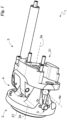
Fig. 1 is a scale representation of an artificial wrist according to the invention; -
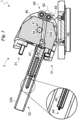
Fig. 2 is a scale representation of a section ofFig. 1 ; and -
Fig. 3 is a scale representation of the artificial wrist in a different position from that shown inFigs. 1 and2 . - Herein, the measures, values, shapes and geometric references (such as perpendicularity and parallelism), when used with words like "about" or other similar terms such as "approximately" or "substantially", are to be understood as except for measurement errors or inaccuracies due to production and/or manufacturing errors and, above all, except for a slight divergence from the value, measure, shape or geometric reference with which it is associated. For example, these terms, if associated with a value, preferably indicate a divergence of not more than 10% from said value.
- Furthermore, when used, terms such as "first", "second", "higher", "lower", "main" and "secondary" do not necessarily identify an order, a priority relationship or a relative position, but can simply be used to distinguish more clearly the different components from each other.
- Unless otherwise indicated, the measurements and data provided in this document are to be considered using International Standard Atmosphere ICAO (ISO 2533).
- With reference to the Figures, the artificial wrist according to the invention is indicated as a whole by the
number 1. - It is suitable to be used to connect an end effector to a support, allowing at least one rotation between the end effector and the support.
- The end effector is preferably a prosthetic device, and specifically a robotic hand. The support is identifiable as a suitably prosthetic robotic arm or an amputated limb.
- The
artificial wrist 1 comprises astatic body 2 adapted to be bound to a support; amovable body 3 adapted to be bound to an end effector; and at least onejunction block 4 between thestatic body 2 and themovable body 3 and defining an axis ofrotation 4a between thestatic body 2 and themovable body 3. - Preferably, the
wrist 1 comprises asingle junction block 4 and therefore thebodies rotation 4a. - The
static body 2 defines a first, suitably barycentriclongitudinal axis 2a. - The first
longitudinal axis 2a is perpendicular to the axis ofrotation 4a and appropriately incident to said axis ofrotation 4a. - The
static body 2 comprises first fastening means 21 for fastening thestatic body 2 to the support. - The
movable body 3 defines a second, suitably barycentriclongitudinal axis 3a. - The second
longitudinal axis 3a is perpendicular to the axis ofrotation 4a and appropriately incident to said axis ofrotation 4a. - The
movable body 3 comprises second fastening means 31 for fastening themovable body 3 to the end effector. - The fastening means 21 and 31 are known in the art.
- The
junction block 4 comprises ahinge 41 defining the axis ofrotation 4a. - The
junction block 4 is suitable to allow and at the same time oppose rotation between thestatic body 2 and themovable body 3, suitably around the axis ofrotation 4a. - It defines, for the
artificial wrist 1, a rest position (Figs. 1-2 ) in which the resulting torque on thebodies bodies Fig. 3 ) in which the resulting torque on thebodies bodies bodies bodies bodies - In the rest configuration, the
longitudinal axes - In the one or more activation configurations, the
longitudinal axes - The
junction block 4 comprises at least onecable 42 bound to thestatic body 2 and themovable body 3; and elastic means 43 placing thecable 42 under tensile stress. Preferably, thejunction block 4 comprises twocables 42, of which afirst cable 42 is adapted to be tensioned by mutual rotation of thebodies second cable 42 is adapted to be tensioned by mutual rotation of thebodies - The action of the
cable 42 and themeans 43 defines the aforesaid resulting torque. Eachcable 42 has one end bound to thestatic body 2, preferably in an integral manner. Thecables 42 are anchored to thestatic body 2 on opposite sides with respect to the axis ofrotation 4a, and specifically to the firstlongitudinal axis 2a. - Each
cable 42 has the other end bound to themovable body 3, suitably in a non-integral manner as hereinafter better described. - The
cable 42 is bound to themovable body 3 on the opposite side of thestatic body 2. For this purpose, themovable body 3 comprises achannel 32 for the passage of the one ormore cables 42. - The
channel 32 has an axis of extension that can be perpendicular to the axis ofrotation 4a. Specifically, the axis of extension of thechannel 32 is inclined to the secondlongitudinal axis 3a. Alternatively, it is substantially parallel to thesecond axis 3a. - Preferably, the
channel 32 comprises afirst sector 32a proximal to thestatic body 2 and asecond sector 32b inclined to the first sector and located on the opposite side of thefirst sector 32a with respect to thestatic body 2. - The
first sector 32a has a first axis of extension substantially inclined to the secondlongitudinal axis 3a. - The
second sector 32b has a second axis of extension substantially parallel to and suitably distinct from the secondlongitudinal axis 3a. - The
elastic means 43 is suitable to store energy during mutual rotation of thebodies bodies 2 and 3) so as to create a torque on thebodies artificial wrist 1 back to the rest position. - In the rest position, the forces of the elastic means 43 and of the at least one
cable 42 mainly cause two opposite and substantially equal torques, so that the resulting torque is zero and therefore such as to maintain theartificial wrist 1 in the rest position. - In the activation position, the forces of the elastic means 43 and of the at least one cable mainly cause two opposite and substantially different torques, so that the resulting torque is non-zero and therefore such as to bring the
artificial wrist 1 back to the rest position. - The
elastic means 43 is preloaded so that in the rest position eachcable 42 is tensioned. - The elastic means 43 is interposed between the
movable body 3 and said at least onecable 42 so that the transition into the activation position causes thecable 42 to move, thus loading theelastic means 43. - They can have one end integral with the
movable body 3 and the other end integral with the at least onecable 42 so that mutual rotation of thebodies cable 42 to move, loads theelastic means 43. - The elastic means 43 comprises a spring, which is suitably a tension spring or specifically a compression spring. Preferably, the elastic means 43 is a compression spring, and the end thereof that is integral with the at least one
cable 42 is located on the opposite side of thestatic body 2 with respect to themovable body 3. - The elastic means 43 is preferably housed inside the
channel 32, which then guides the sliding of saidelastic means 43. - In order to integrally bind the end to the at least one
cable 42, thejunction block 4 may comprise afastening head 44 for fastening thecable 42 to themeans 43. - The
junction block 4 may comprise at least onepulley 45 defining a groove for the sliding of the at least onecable 42. - The
pulley 45 is placed at the interface area between thebodies - Preferably, it is bound, and in detail hinged to the
movable body 3 so as to intercept thecable 42 before it reaches thechannel 32. - Advantageously, the
junction block 4 comprises twopulleys 45 alongside each other so that the sliding grooves define a duct inside which the at least onecable 42 slides, substantially without the possibility of coming out sideways. - The
junction block 4 may comprise one or more guiding pins 46 to direct the at least onecable 42. - The guiding pins 46 are located along the path of each
cable 42 and define surfaces along which thecable 42 slides during rotation, and therefore a change in position of theartificial wrist 1. - They may be bound, suitably in an integral manner, to the
static body 2 and/or to themovable body 3. - Finally, the
artificial wrist 1 can comprise a locking member 5 to couple themovable body 3 to thestatic body 2. - The locking member 5 is suitable to integrally couple the
bodies - It is suitable to lock the
artificial wrist 1 in one or more activation positions, preferably in the rest position. - The locking member 5 is known per se. It can comprise a locking member provided with a pin and two positions of stable equilibrium, and a spring presser, which can be actuated manually by a suitable lever.
- The operation of the
artificial wrist 1, previously described in structural terms, is as follows. - Once the
artificial wrist 1 is bound to the support (for example a robotic arm, for example a prosthetic arm, or an amputated limb) and to an end effector, such as a robotic hand, it is ready. - Initially, the
artificial wrist 1 is in the rest position (Figs. 1 and2 ). - When an external force, for example acting on the end effector, creates a torque commanding mutual rotation of the end effector and the support around the axis of
rotation 4a, thebodies rotation 4a moving away from the rest position. - This rotation, caused by said external force, between the
bodies elastic means 43. Thecable 42 thus slides in thechannel 32b and causes the elastic means 43 to be compressed (i.e. storage of energy). - The
bodies Fig. 3 ) in which the forces created by thecable 42 and the elastic means 43 generate a resulting torque counteracting that given by the external force. - It should be pointed out that during this rotation in the
artificial wrist 1 described herein, representing one of the possible embodiments of thewrist 1 according to the invention, only one of the cables 42 (for example the first cable) is tensioned while the other cable 42 (for example the second cable) is released and, as shown inFig. 3 , can become relaxed. - When the external force is no longer applied, the elastic means 43 releases the stored energy by causing a rotation opposite to the previous one and such as to bring the
artificial wrist 1 back to the rest position. - The
artificial wrist 1 according to the invention achieves important advantages. - In fact, the
artificial wrist 1 has extremely simple mechanics and is therefore easy to manufacture even considering the small dimensions required. - Another advantage is that the
artificial wrist 1, compared to known artificial wrists, has limited dimensions and weight, thus resulting in high comfort of use and low manufacturing costs. - These advantages are due to the innovative use of
cables 42 andelastic means 43 to control the rotation of thewrist 1, particularly to the particular solution chosen for anchoring thecables 42, and more particularly to the interposition ofelastic means 43 between thecable 42 and themovable body 3. - Another advantage is that the
artificial wrist 1 allows large rotation angles (up to 140° or even larger depending on the selected configuration of thewrist 1 according to the invention). - For example, the embodiment described above and shown in
Figs. 1-3 has the same rotation angle in both directions (extension and flexion) substantially equal to 70°. - The invention is susceptible of variations falling within the scope of the inventive concept as defined by the claims. In one example not falling under the scope of the claimed invention, the elastic means 43 and the at least one
cable 42 may coincide and be identifiable as an elastic cable. Therefore, thejunction block 4 may comprise at least one elastic cable, and preferably two elastic cables, one operating in the first direction of rotation, the other in the second direction of rotation. - Another possible alternative may comprise integral connection of the at least one
cable 42 to the movable body and interposition of the elastic means 43 between thecable 42 and thestatic body 2, and in particular the creation of a sliding duct for the elastic means 43 and thecable 42 in thestatic body 2 instead of in themovable body 3. - In this context, all details are replaceable by equivalent elements, and the materials, shapes and dimensions may be any type of materials, shapes and dimensions.
- The scope of the invention is solely defined by the appended claims.
Claims (9)
- An artificial wrist (1) comprising:- a static body (2) adapted to be bound to a support;- a movable body (3) adapted to be bound to an end effector;- a junction block (4) between said static body (2) and said movable body (3) and defining at least one axis of rotation (4a) between said static body and said movable body;
and characterised in that said junction block comprises- at least one cable (42) having one end bound to said static body (2) and the other end to said movable body (3) so as to be moved by mutual rotation of said static body (2) and said movable body (3) around said axis of rotation (4a);- elastic means (43) placing said cable (42) under tensile stress and working in opposition to the movement of said cable (42) so as to define a rest position in which said cable (42) and said elastic means (43) exert a zero resulting torque on said static body (2) and said movable body (3), and an activation position in which said cable (42) and elastic means (43) exert a non-zero resulting torque on said static body (2) and said movable body (3), bringing said static body (2) and said movable body (3) back to said rest position. - The artificial wrist (1) according to claim 1, wherein said junction block (4) comprises two of said at least one cable (42), of which a first cable (42) is adapted to be tensioned by mutual rotation of said bodies (2, 3) in a first direction of rotation, and a second cable (42) is adapted to be tensioned by mutual rotation of said bodies (2, 3) in a second direction opposite to said first direction of rotation.
- The artificial wrist (1) according to claim 2, wherein said cables (42) are bound to said static body (2) on opposite sides with respect to said axis of rotation (4a).
- The artificial wrist (1) according to at least one of the preceding claims, wherein said elastic means (43) is interposed between said movable body (3) and said at least one cable (42) so that the transition into said activation position causes said cable (42) to move, thus loading said elastic means (43).
- The artificial wrist (1) according to the preceding claim, wherein said elastic means (43) has one end integral with said movable body (3) and the other end integral with said cable (42).
- The artificial wrist (1) according to at least one of claims 4-5, wherein said elastic means (43) is a compression spring.
- The artificial wrist (1) according to the preceding claim, wherein the end of said compression spring that is integral with said cable (42) is located on the opposite side of said static body (2) with respect to said movable body (3).
- The artificial wrist (1) according to at least one of the preceding claims, wherein said cable (42) is bound to said movable body (3) on the opposite side of said static body (2); and wherein said movable body (3) comprises a channel (32) for the passage of said cable (42).
- The artificial wrist (1) according to the preceding claim, wherein said elastic means (43) is in said channel (32) which guides the sliding of said elastic means (43).
Applications Claiming Priority (2)
| Application Number | Priority Date | Filing Date | Title |
|---|---|---|---|
| IT102018000003961A IT201800003961A1 (en) | 2018-03-26 | 2018-03-26 | ARTIFICIAL WRIST |
| PCT/IB2019/052172 WO2019186319A1 (en) | 2018-03-26 | 2019-03-18 | Artificial wrist |
Publications (3)
| Publication Number | Publication Date |
|---|---|
| EP3927288A1 EP3927288A1 (en) | 2021-12-29 |
| EP3927288C0 EP3927288C0 (en) | 2025-06-25 |
| EP3927288B1 true EP3927288B1 (en) | 2025-06-25 |
Family
ID=62597942
Family Applications (1)
| Application Number | Title | Priority Date | Filing Date |
|---|---|---|---|
| EP19716987.3A Active EP3927288B1 (en) | 2018-03-26 | 2019-03-18 | Artificial wrist |
Country Status (4)
| Country | Link |
|---|---|
| US (1) | US11833065B2 (en) |
| EP (1) | EP3927288B1 (en) |
| IT (1) | IT201800003961A1 (en) |
| WO (1) | WO2019186319A1 (en) |
Citations (3)
| Publication number | Priority date | Publication date | Assignee | Title |
|---|---|---|---|---|
| DE307338C (en) * | 1916-06-30 | 1918-08-14 | Artificial Hand | |
| US20070173955A1 (en) * | 2002-07-12 | 2007-07-26 | Motion Control, Inc. | Wrist device for use with a prosthetic limb |
| US20170281368A1 (en) * | 2014-10-03 | 2017-10-05 | Touch Bionics Limited | Wrist device for a prosthetic limb |
Family Cites Families (6)
| Publication number | Priority date | Publication date | Assignee | Title |
|---|---|---|---|---|
| FR2557450B1 (en) * | 1983-10-05 | 1986-05-02 | Monestier Jacques | IMPROVEMENTS ON TOTAL HAND PROSTHESES |
| JP3086452B1 (en) * | 1999-05-19 | 2000-09-11 | 原田電子工業株式会社 | Movable finger for artificial limb, artificial hand using the movable finger, and control device for the movable finger |
| US7048768B1 (en) * | 2004-01-30 | 2006-05-23 | John Hoover Rouse | Multi-function body-powered prosthetic wrist unit and method |
| US20070213842A1 (en) * | 2006-03-07 | 2007-09-13 | Simmons Randy S | Prosthetic arm |
| US9474631B2 (en) * | 2013-07-22 | 2016-10-25 | Invisible Hand Enterprises, Llc | Gripping device with switchable prehension modes |
| EP3506857B1 (en) * | 2016-09-02 | 2025-07-09 | Touch Bionics Limited | Systems and methods for prosthetic wrist rotation |
-
2018
- 2018-03-26 IT IT102018000003961A patent/IT201800003961A1/en unknown
-
2019
- 2019-03-18 WO PCT/IB2019/052172 patent/WO2019186319A1/en not_active Ceased
- 2019-03-18 US US17/422,806 patent/US11833065B2/en active Active
- 2019-03-18 EP EP19716987.3A patent/EP3927288B1/en active Active
Patent Citations (3)
| Publication number | Priority date | Publication date | Assignee | Title |
|---|---|---|---|---|
| DE307338C (en) * | 1916-06-30 | 1918-08-14 | Artificial Hand | |
| US20070173955A1 (en) * | 2002-07-12 | 2007-07-26 | Motion Control, Inc. | Wrist device for use with a prosthetic limb |
| US20170281368A1 (en) * | 2014-10-03 | 2017-10-05 | Touch Bionics Limited | Wrist device for a prosthetic limb |
Also Published As
| Publication number | Publication date |
|---|---|
| US20220125605A1 (en) | 2022-04-28 |
| IT201800003961A1 (en) | 2019-09-26 |
| EP3927288C0 (en) | 2025-06-25 |
| US11833065B2 (en) | 2023-12-05 |
| WO2019186319A1 (en) | 2019-10-03 |
| EP3927288A1 (en) | 2021-12-29 |
Similar Documents
| Publication | Publication Date | Title |
|---|---|---|
| Tavakoli et al. | Adaptive under-actuated anthropomorphic hand: ISR-SoftHand | |
| US11278432B2 (en) | Underactuated prosthetic hand | |
| Nguyen | Constructing stable grasps | |
| CN107848122B (en) | Robot with force measuring device | |
| US8393254B2 (en) | Gripping device | |
| US8100986B2 (en) | Prosthetic finger | |
| US20140366675A1 (en) | Articulated Limb for a Robot or Haptic Interface and Robot and Haptic Interface Comprising at Least One Such Articulated Limb | |
| US20140081425A1 (en) | Gripping device with switchable opening modes | |
| US11833065B2 (en) | Artificial wrist | |
| US10400944B2 (en) | Counterbalance system and/or a method for counterbalancing a load | |
| EP3790514B1 (en) | Prosthetic finger | |
| Radkhah et al. | A study of the passive rebound behavior of bipedal robots with stiff and different types of elastic actuation | |
| US4962595A (en) | Ski shoe | |
| Medina et al. | Design and characterization of a novel mechanism of multiple joint stiffness (MMJS) | |
| Merlet | Analysis of wire elasticity for wire-driven parallel robots | |
| WO1992005016A1 (en) | Methods and apparatus for passively compensating for the effects of gravity upon articulated structures | |
| GB1406214A (en) | Locking device for a goods handling container | |
| US11883956B2 (en) | Wearable gravity compensation apparatus capable of multiple degrees of freedom of movement | |
| Goetz | Design, realization, and verification of a planar, tendon-driven, variable stiffness finger | |
| US12296464B2 (en) | Gripper | |
| Birglen | Haptic devices based on parallel mechanisms. state of the art | |
| US20160325436A1 (en) | Robot arm joint, particularly for haptic and/or cobotic uses | |
| Last et al. | An extended inverse kinematic model of the HEXA-parallel-robot for calibration purposes | |
| JP7631861B2 (en) | Assistive Device | |
| SU1484677A1 (en) | Master arm of tracing manipulator |
Legal Events
| Date | Code | Title | Description |
|---|---|---|---|
| STAA | Information on the status of an ep patent application or granted ep patent |
Free format text: STATUS: UNKNOWN |
|
| STAA | Information on the status of an ep patent application or granted ep patent |
Free format text: STATUS: THE INTERNATIONAL PUBLICATION HAS BEEN MADE |
|
| STAA | Information on the status of an ep patent application or granted ep patent |
Free format text: STATUS: THE APPLICATION IS DEEMED TO BE WITHDRAWN |
|
| STAA | Information on the status of an ep patent application or granted ep patent |
Free format text: STATUS: THE INTERNATIONAL PUBLICATION HAS BEEN MADE |
|
| PUAI | Public reference made under article 153(3) epc to a published international application that has entered the european phase |
Free format text: ORIGINAL CODE: 0009012 |
|
| STAA | Information on the status of an ep patent application or granted ep patent |
Free format text: STATUS: REQUEST FOR EXAMINATION WAS MADE |
|
| 17P | Request for examination filed |
Effective date: 20210907 |
|
| AK | Designated contracting states |
Kind code of ref document: A1 Designated state(s): AL AT BE BG CH CY CZ DE DK EE ES FI FR GB GR HR HU IE IS IT LI LT LU LV MC MK MT NL NO PL PT RO RS SE SI SK SM TR |
|
| STAA | Information on the status of an ep patent application or granted ep patent |
Free format text: STATUS: EXAMINATION IS IN PROGRESS |
|
| 17Q | First examination report despatched |
Effective date: 20221222 |
|
| GRAP | Despatch of communication of intention to grant a patent |
Free format text: ORIGINAL CODE: EPIDOSNIGR1 |
|
| STAA | Information on the status of an ep patent application or granted ep patent |
Free format text: STATUS: GRANT OF PATENT IS INTENDED |
|
| INTG | Intention to grant announced |
Effective date: 20250226 |
|
| GRAS | Grant fee paid |
Free format text: ORIGINAL CODE: EPIDOSNIGR3 |
|
| GRAA | (expected) grant |
Free format text: ORIGINAL CODE: 0009210 |
|
| STAA | Information on the status of an ep patent application or granted ep patent |
Free format text: STATUS: THE PATENT HAS BEEN GRANTED |
|
| AK | Designated contracting states |
Kind code of ref document: B1 Designated state(s): AL AT BE BG CH CY CZ DE DK EE ES FI FR GB GR HR HU IE IS IT LI LT LU LV MC MK MT NL NO PL PT RO RS SE SI SK SM TR |
|
| REG | Reference to a national code |
Ref country code: GB Ref legal event code: FG4D |
|
| REG | Reference to a national code |
Ref country code: CH Ref legal event code: EP |
|
| REG | Reference to a national code |
Ref country code: CH Ref legal event code: EP |
|
| REG | Reference to a national code |
Ref country code: IE Ref legal event code: FG4D |
|
| REG | Reference to a national code |
Ref country code: DE Ref legal event code: R096 Ref document number: 602019071516 Country of ref document: DE |
|
| U01 | Request for unitary effect filed |
Effective date: 20250709 |
|
| U07 | Unitary effect registered |
Designated state(s): AT BE BG DE DK EE FI FR IT LT LU LV MT NL PT RO SE SI Effective date: 20250723 |
|
| PG25 | Lapsed in a contracting state [announced via postgrant information from national office to epo] |
Ref country code: GR Free format text: LAPSE BECAUSE OF FAILURE TO SUBMIT A TRANSLATION OF THE DESCRIPTION OR TO PAY THE FEE WITHIN THE PRESCRIBED TIME-LIMIT Effective date: 20250926 Ref country code: NO Free format text: LAPSE BECAUSE OF FAILURE TO SUBMIT A TRANSLATION OF THE DESCRIPTION OR TO PAY THE FEE WITHIN THE PRESCRIBED TIME-LIMIT Effective date: 20250925 |
|
| PG25 | Lapsed in a contracting state [announced via postgrant information from national office to epo] |
Ref country code: HR Free format text: LAPSE BECAUSE OF FAILURE TO SUBMIT A TRANSLATION OF THE DESCRIPTION OR TO PAY THE FEE WITHIN THE PRESCRIBED TIME-LIMIT Effective date: 20250625 |
|
| PG25 | Lapsed in a contracting state [announced via postgrant information from national office to epo] |
Ref country code: RS Free format text: LAPSE BECAUSE OF FAILURE TO SUBMIT A TRANSLATION OF THE DESCRIPTION OR TO PAY THE FEE WITHIN THE PRESCRIBED TIME-LIMIT Effective date: 20250925 |
|
| PG25 | Lapsed in a contracting state [announced via postgrant information from national office to epo] |
Ref country code: IS Free format text: LAPSE BECAUSE OF FAILURE TO SUBMIT A TRANSLATION OF THE DESCRIPTION OR TO PAY THE FEE WITHIN THE PRESCRIBED TIME-LIMIT Effective date: 20251025 |
|
| PG25 | Lapsed in a contracting state [announced via postgrant information from national office to epo] |
Ref country code: SM Free format text: LAPSE BECAUSE OF FAILURE TO SUBMIT A TRANSLATION OF THE DESCRIPTION OR TO PAY THE FEE WITHIN THE PRESCRIBED TIME-LIMIT Effective date: 20250625 |
|
| PG25 | Lapsed in a contracting state [announced via postgrant information from national office to epo] |
Ref country code: CZ Free format text: LAPSE BECAUSE OF FAILURE TO SUBMIT A TRANSLATION OF THE DESCRIPTION OR TO PAY THE FEE WITHIN THE PRESCRIBED TIME-LIMIT Effective date: 20250625 |
|
| PG25 | Lapsed in a contracting state [announced via postgrant information from national office to epo] |
Ref country code: PL Free format text: LAPSE BECAUSE OF FAILURE TO SUBMIT A TRANSLATION OF THE DESCRIPTION OR TO PAY THE FEE WITHIN THE PRESCRIBED TIME-LIMIT Effective date: 20250625 |
|
| PG25 | Lapsed in a contracting state [announced via postgrant information from national office to epo] |
Ref country code: SK Free format text: LAPSE BECAUSE OF FAILURE TO SUBMIT A TRANSLATION OF THE DESCRIPTION OR TO PAY THE FEE WITHIN THE PRESCRIBED TIME-LIMIT Effective date: 20250625 |
|
| PG25 | Lapsed in a contracting state [announced via postgrant information from national office to epo] |
Ref country code: ES Free format text: LAPSE BECAUSE OF FAILURE TO SUBMIT A TRANSLATION OF THE DESCRIPTION OR TO PAY THE FEE WITHIN THE PRESCRIBED TIME-LIMIT Effective date: 20250625 |
|
| U20 | Renewal fee for the european patent with unitary effect paid |
Year of fee payment: 8 Effective date: 20260116 |
|
| PGFP | Annual fee paid to national office [announced via postgrant information from national office to epo] |
Ref country code: GB Payment date: 20260324 Year of fee payment: 8 |
|
| PLBE | No opposition filed within time limit |
Free format text: ORIGINAL CODE: 0009261 |
|
| STAA | Information on the status of an ep patent application or granted ep patent |
Free format text: STATUS: NO OPPOSITION FILED WITHIN TIME LIMIT |
|
| REG | Reference to a national code |
Ref country code: CH Ref legal event code: L10 Free format text: ST27 STATUS EVENT CODE: U-0-0-L10-L00 (AS PROVIDED BY THE NATIONAL OFFICE) Effective date: 20260507 |