EP3927112A1 - Quick heating module and air conditioner - Google Patents
Quick heating module and air conditioner Download PDFInfo
- Publication number
- EP3927112A1 EP3927112A1 EP20787252.4A EP20787252A EP3927112A1 EP 3927112 A1 EP3927112 A1 EP 3927112A1 EP 20787252 A EP20787252 A EP 20787252A EP 3927112 A1 EP3927112 A1 EP 3927112A1
- Authority
- EP
- European Patent Office
- Prior art keywords
- electromagnetic induction
- heat exchanger
- induction heating
- heating member
- heating module
- Prior art date
- Legal status (The legal status is an assumption and is not a legal conclusion. Google has not performed a legal analysis and makes no representation as to the accuracy of the status listed.)
- Granted
Links
Images





Classifications
-
- H—ELECTRICITY
- H05—ELECTRIC TECHNIQUES NOT OTHERWISE PROVIDED FOR
- H05B—ELECTRIC HEATING; ELECTRIC LIGHT SOURCES NOT OTHERWISE PROVIDED FOR; CIRCUIT ARRANGEMENTS FOR ELECTRIC LIGHT SOURCES, IN GENERAL
- H05B6/00—Heating by electric, magnetic or electromagnetic fields
- H05B6/02—Induction heating
- H05B6/10—Induction heating apparatus, other than furnaces, for specific applications
- H05B6/105—Induction heating apparatus, other than furnaces, for specific applications using a susceptor
- H05B6/108—Induction heating apparatus, other than furnaces, for specific applications using a susceptor for heating a fluid
-
- F—MECHANICAL ENGINEERING; LIGHTING; HEATING; WEAPONS; BLASTING
- F24—HEATING; RANGES; VENTILATING
- F24F—AIR-CONDITIONING; AIR-HUMIDIFICATION; VENTILATION; USE OF AIR CURRENTS FOR SCREENING
- F24F1/00—Room units for air-conditioning, e.g. separate or self-contained units or units receiving primary air from a central station
- F24F1/02—Self-contained room units for air-conditioning, i.e. with all apparatus for treatment installed in a common casing
- F24F1/0373—Self-contained room units for air-conditioning, i.e. with all apparatus for treatment installed in a common casing characterised by heating arrangements
- F24F1/0375—Self-contained room units for air-conditioning, i.e. with all apparatus for treatment installed in a common casing characterised by heating arrangements with additional radiant heat-discharging elements, e.g. electric heaters
-
- F—MECHANICAL ENGINEERING; LIGHTING; HEATING; WEAPONS; BLASTING
- F24—HEATING; RANGES; VENTILATING
- F24F—AIR-CONDITIONING; AIR-HUMIDIFICATION; VENTILATION; USE OF AIR CURRENTS FOR SCREENING
- F24F1/00—Room units for air-conditioning, e.g. separate or self-contained units or units receiving primary air from a central station
- F24F1/02—Self-contained room units for air-conditioning, i.e. with all apparatus for treatment installed in a common casing
- F24F1/0373—Self-contained room units for air-conditioning, i.e. with all apparatus for treatment installed in a common casing characterised by heating arrangements
- F24F1/0378—Self-contained room units for air-conditioning, i.e. with all apparatus for treatment installed in a common casing characterised by heating arrangements using thermoelectric or thermomagnetic means, e.g. Peltier elements
-
- H—ELECTRICITY
- H05—ELECTRIC TECHNIQUES NOT OTHERWISE PROVIDED FOR
- H05B—ELECTRIC HEATING; ELECTRIC LIGHT SOURCES NOT OTHERWISE PROVIDED FOR; CIRCUIT ARRANGEMENTS FOR ELECTRIC LIGHT SOURCES, IN GENERAL
- H05B6/00—Heating by electric, magnetic or electromagnetic fields
- H05B6/02—Induction heating
- H05B6/36—Coil arrangements
- H05B6/365—Coil arrangements using supplementary conductive or ferromagnetic pieces
-
- H—ELECTRICITY
- H05—ELECTRIC TECHNIQUES NOT OTHERWISE PROVIDED FOR
- H05B—ELECTRIC HEATING; ELECTRIC LIGHT SOURCES NOT OTHERWISE PROVIDED FOR; CIRCUIT ARRANGEMENTS FOR ELECTRIC LIGHT SOURCES, IN GENERAL
- H05B2206/00—Aspects relating to heating by electric, magnetic, or electromagnetic fields covered by group H05B6/00
- H05B2206/02—Induction heating
- H05B2206/022—Special supports for the induction coils
Definitions
- the present application relates to the field of heating apparatus technologies, and particularly to a quick heating module and an air conditioner.
- a refrigerant heating structure in a prior art, in which an electric heater is directly mounted in a copper tube to heat the refrigerant, so as to improve thermal efficiency of the refrigerant.
- the copper tube of this structure has an over complicated molding manufacturing technology, and a junction of the electric heater and the copper tube has a poor sealing reliability, and the electric heater may have a dry heating phenomenon under certain conditions.
- electrical safety problems such as the dry heating phenomenon of an electric heating portion, a line breakdown, or the like, are unable to be avoided.
- the present application seeks to solve at least one of the problems existing in the prior art. To this end, the present application provides a quick heating module for quickly heating a refrigerant.
- the present application aims to provide an air conditioner in which air discharged from a compressor may be quickly heated.
- a quick heating module includes: a refrigerant heat exchanger defining a refrigerant passage therein; an electromagnetic induction heating member configured to heat the refrigerant heat exchanger; and an alternating magnetic field generator provided close to the electromagnetic induction heating member and emitting an alternating magnetic field to the electromagnetic induction heating member.
- the electromagnetic induction heating member is provided on the refrigerant heat exchanger, and the alternating magnetic field generator is provided for the electromagnetic induction heating member, such that the electromagnetic induction heating member generates heat under the action of electromagnetic induction to heat a refrigerant in the refrigerant heat exchanger; with this refrigerant heating method, the refrigerant in a cooling apparatus or a heating apparatus may be quickly heated, and electricity may be separated from the refrigerant.
- the electromagnetic induction heating member is provided between the refrigerant heat exchanger and the alternating magnetic field generator, and the electromagnetic induction heating member directly contacts the refrigerant heat exchanger.
- the refrigerant heat exchanger is configured as a microchannel heat exchanger.
- the electromagnetic induction heating member is configured as a plate.
- the electromagnetic induction heating member has a thickness less than or equal to 5 mm.
- the electromagnetic induction heating member is connected to the refrigerant heat exchanger by a fastener.
- the electromagnetic induction heating member and the refrigerant heat exchanger are provided with solder or a soldering flake therebetween and connected by welding.
- the electromagnetic induction heating member and the refrigerant heat exchanger are provided with a heat conducting agent layer therebetween.
- the alternating magnetic field generator and the electromagnetic induction heating member are provided with a heat insulation member therebetween.
- the alternating magnetic field generator is configured as a coil disk.
- the coil disk and the electromagnetic induction heating member have a distance of 1-20 mm therebetween.
- an overlapping area of orthographic projections of the coil disk and the electromagnetic induction heating member on the refrigerant heat exchanger at least accounts for half of an area of an orthographic projection of the electromagnetic induction heating member on the refrigerant heat exchanger.
- the coil disk includes: a coil support; and a wire body wound on the coil support, two ends of the wire body serving as wiring terminals.
- the coil disk further includes a magnetic strip, which is provided on the coil support.
- an extension line of the magnetic strip is perpendicular to a tangent line of the wire body at an intersection with the extension line.
- the coil support is provided with a magnetic-strip fixing groove configured to limit the magnetic strip.
- the coil support defines a wire slot, and the wire body is clamped in the wire slot.
- the coil support is provided with a wire pressing hook configured to lock the wiring terminal.
- the coil support is substantially rectangular, and the wire body is wound into a flat annular coil.
- the coil disk includes a voltage resistant sheet provided on the coil support and located on a side of the wire body facing the electromagnetic induction heating member.
- the electromagnetic induction heating member is provided on the refrigerant heat exchanger, and the quick heating module further includes an outer protective member, and the refrigerant heat exchanger and the coil disk are connected to the outer protective member, so as to keep a distance between the coil disk and the electromagnetic induction heating member.
- An air conditioner includes: a compressor; and the quick heating module according to the above-mentioned embodiment of the present application, the refrigerant passage of the refrigerant heat exchanger being connected with a discharge port of the compressor.
- an exhaust side of the compressor is provided with the above-mentioned quick heating module, such that the air discharged from the compressor is heated quickly, thus meeting a requirement of quick heating after the air conditioner is started in winter.
- the electromagnetic induction heating member is provided on the refrigerant heat exchanger, and the alternating magnetic field generator is provided for the electromagnetic induction heating member, such that the electromagnetic induction heating member generates the heat under the action of electromagnetic induction to heat the refrigerant in the refrigerant heat exchanger, and the electricity may be separated from the refrigerant, thus reducing the process requirement and the machining difficulty of the refrigerant heat exchanger, and avoiding the electrical safety problems, such as the dry heating phenomenon of the electric heating portion, the line breakdown , or the like.
- a quick heating module 5 according to an embodiment of the present application will be described below with reference to the accompanying drawings, and the quick heating module 5 is used in a refrigerant circulation system, such as an air conditioner, a water heater, or the like.
- the quick heating module 5 includes: a refrigerant heat exchanger 54, an electromagnetic induction heating member 53 and an alternating magnetic field generator 52.
- the refrigerant heat exchanger 54 has a refrigerant passage defined therein, and the electromagnetic induction heating member 53 is configured to heat the refrigerant heat exchanger 54, so as to heat a refrigerant flowing through the refrigerant passage, and the alternating magnetic field generator 52 is provided close to the electromagnetic induction heating member 53 and emits an alternating magnetic field to the electromagnetic induction heating member 53.
- the electromagnetic induction heating member 53 when the electromagnetic induction heating member 53 is located in a changing magnetic field, an induced electromotive force is generated in the electromagnetic induction heating member 53 by electromagnetic induction. Since the electromagnetic induction heating member 53 has a resistance, a current may be generated in the electromagnetic induction heating member 53, and the distribution of the current in the electromagnetic induction heating member 53 is different along with a surface shape and magnetic flux distribution of the electromagnetic induction heating member 53, and an eddy current formed by a path of the current generates heat in the electromagnetic induction heating member 53, such that after the alternating magnetic field generator 52 generates an alternating magnetic field, and the electromagnetic induction heating member 53 may heat the refrigerant heat exchanger 54, so as to quickly heat the refrigerant in the refrigerant passage.
- the alternating magnetic field generator 52 is energized to impel the electromagnetic induction heating member 53 to generate heat, instead of concentrating a heat source at one point and then diffusing outwards by the heat source point, such that no heat concentration point exists on the refrigerant heat exchanger 54, and electrical safety problems, such as a dry heating phenomenon, a line breakdown, or the like, may be avoided.
- the electromagnetic induction heating member 53 is provided on the refrigerant heat exchanger 54, and the alternating magnetic field generator 52 is provided for the electromagnetic induction heating member 53, such that the electromagnetic induction heating member 53 generates heat under the action of electromagnetic induction to heat the refrigerant in the refrigerant heat exchanger 54; with this refrigerant heating method, the refrigerant in a cooling apparatus or a heating apparatus may be quickly heated.
- an electric heater of a refrigerant heating structure is directly mounted in a copper tube to heat the refrigerant, and the refrigerant may be in an electricity contact state.
- the alternating magnetic field generator 52 is only required to be energized to generate the alternating magnetic field, without direct electrification of the refrigerant heat exchanger 54, such that the electricity may be isolated from the refrigerant.
- the electromagnetic induction heating member 53 has various structural forms.
- the electromagnetic induction heating member 53 is configured as a plate, and fixedly mounted after being machined, such that the electromagnetic induction heating member 53 is quite easy to be machined and mounted.
- at least a part of the electromagnetic induction heating member 53 has a strip shape, and the electromagnetic induction heating member 53 is inserted between adjacent refrigerant pipes, such that a heat exchange space may be fully used to dispose the electromagnetic induction heating member 53.
- the electromagnetic induction heating member 53 serves as both a heating member and a heat conductor, and the heat generated by the electromagnetic induction heating member 53 may be quickly conducted to the refrigerant passage of the refrigerant heat exchanger 54, and the electromagnetic induction heating member 53 is not required to store heat.
- the whole plate should not be too thick; on the one hand, an over-thick plate consumes too much heat, thus reducing a heat utilization efficiency, and on the other hand, the over-thick plate may increase a volume and a weight of the whole quick heating module 5.
- the electromagnetic induction heating member 53 is configured as a component made of a magnetic conduction material; for example, the electromagnetic induction heating member 53 contains iron, nickel, iron oxide, chromium oxide, or the like.
- the magnetic conduction material capable of generating electromagnetic induction may be any material disclosed in the prior art, which is not limited herein.
- the electromagnetic induction heating member 53 may be configured as a single-layer plate integrally formed of a magnetic conduction material, such as an iron plate, an iron oxide plate, or a chromium oxide plate.
- the electromagnetic induction heating member 53 may also be configured as a composite layer member, and at least one layer of the electromagnetic induction heating member 53 is configured as a magnetic conduction material layer, and other layers may be provided as required.
- the electromagnetic induction heating member 53 may also be configured as a sprayed layer or a coating made of a magnetic conduction material.
- a protection plate or a supporting plate, or the like may be provided on a surface of the refrigerant heat exchanger 54, and the electromagnetic induction heating member 53 may be configured as a coating sprayed on a surface of the protection plate or the supporting plate.
- the electromagnetic induction heating member 53 is even configured as a coating sprayed on the surface of the refrigerant heat exchanger 54.
- a pipe wall of the refrigerant passage is made of a magnetic conduction material and forms the electromagnetic induction heating member 53.
- the pipes of the refrigerant heat exchanger 54 configured to circulate the refrigerant are made of magnetic conduction materials, such that the pipe wall of the refrigerant passage directly generates heat and heats the refrigerant under an alternating magnetic field, and the heat utilization efficiency may be further improved.
- a structure type of the refrigerant heat exchanger 54 is not limited.
- the refrigerant heat exchanger 54 may be configured as a plate heat exchanger, or even the refrigerant heat exchanger 54 may be formed of only one metal pipe, and a pipe cavity of the metal pipe forms the refrigerant passage.
- the refrigerant heat exchanger 54 is configured as a microchannel heat exchanger 540, and a type of which is not limited.
- the microchannel heat exchanger 540 is used for the refrigerant to flow through, such that the refrigerant flowing through the microchannel heat exchanger 540 may be guided into a small streams, thus greatly increasing a specific surface area, and significantly improving a heating efficiency.
- the microchannel heat exchanger 540 includes a collecting pipe 541, and in some other embodiments, the microchannel heat exchanger 540 includes a collecting pipe 541 and a plurality of flat pipes.
- the electromagnetic induction heating member 53 may be provided on the microchannel heat exchanger 540 in any one of the above-mentioned manners, which is not limited herein. In addition to the above-mentioned manner, at least a part of the electromagnetic induction heating member 53 may be inserted between two adjacent flat pipes, which is equivalent to the above description that the strip-shaped part of the electromagnetic induction heating member 53 is inserted between the adjacent refrigerant pipes.
- the electromagnetic induction heating member 53 is provided corresponding to the microchannel heat exchanger 540 in this way, various forms may be adopted, such that a surface space of the microchannel heat exchanger 540 may be fully utilized.
- the electromagnetic induction heating member 53 is configured as a plate and provided on one side of the microchannel heat exchanger 540. More specifically, an inlet-outlet pipe 542 is connected to each of the two collecting pipes 541, such that the refrigerant may flow into and out of the collecting pipe.
- the two collecting pipes 541 are arranged in parallel.
- the microchannel heat exchanger 540 can be formed in various shapes, such as a groove shape, a square shape, or the like, and the shape of the electromagnetic induction heating member 53 should be adapted correspondingly.
- the electromagnetic induction heating member 53 may also be formed into a square tube shape, and at this point, the square tube of the electromagnetic induction heating member 53 may be fitted over the square tube of the microchannel heat exchanger 540 or the square tube of the microchannel heat exchanger 540 may be fitted over the square tube of the electromagnetic induction heating member 53.
- the flat pipe is provided along the shape of the microchannel heat exchanger 540, and a plurality of parallel flat pipes or one sinuous flat pipe may be provided.
- the microchannel heat exchanger 540 has a rectangular overall shape, and the electromagnetic induction heating member 53 is configured as a rectangular plate.
- the microchannel heat exchanger 540 further includes a microchannel base plate 543, which is located between the two collecting pipes 541, and the electromagnetic induction heating member 53 is connected to the microchannel base plate 543.
- the quick heating module 5 is flat as a whole, which facilitates the quick heating module to be mounted in a narrow space.
- various connection modes may be adopted between the electromagnetic induction heating member 53 and the refrigerant heat exchanger 54.
- the electromagnetic induction heating member 53 is connected to the refrigerant heat exchanger 54 by a fastener, thus guaranteeing a tight connection therebetween.
- solder or a soldering flake is provided between the electromagnetic induction heating member 53 and the refrigerant heat exchanger 54, and a welding connection is performed, thus guaranteeing a tight and firm connection therebetween.
- a heat conducting agent layer is provided between the electromagnetic induction heating member 53 and the refrigerant heat exchanger 54 to improve a heat transfer efficiency.
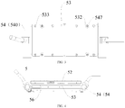
- a plurality of heat-exchanger threaded holes 545 are defined in the microchannel heat exchanger 540, and heating-member via holes 531 are correspondingly defined in the electromagnetic induction heating member 53, and the electromagnetic induction heating member 53 is connected to the heat-exchanger threaded holes 545 by inserting the plurality of heating-member fasteners 533 through the heating-member via holes 531, such that the electromagnetic induction heating member 53 and the refrigerant heat exchanger 54 are connected into a whole.
- a plurality of heat-exchanger via holes 546 are defined in the microchannel heat exchanger 540, and the microchannel heat exchanger 540 is connected into a supporting structure by inserting a plurality of heat-exchanger fasteners 547 through the heat-exchanger via holes 546.
- the electromagnetic induction heating member 53 is provided with heating-member escaping holes 532 corresponding to the plurality of heat-exchanger fasteners 547 to avoid affecting a mounting operation of the heat-exchanger fasteners 547.
- the electromagnetic induction heating member 53 is provided between the refrigerant heat exchanger 54 and the alternating magnetic field generator 52, and directly contacts the refrigerant heat exchanger 54, thus reducing a range of the alternating magnetic field and unnecessary energy consumption.
- an area of a projection of the electromagnetic induction heating member 53 on the refrigerant heat exchanger 54 is greater than half of an area of the refrigerant heat exchanger 54, thus effectively ensuring that the heat absorbed by the electromagnetic induction heating member 53 is transferred to the refrigerant heat exchanger 54.
- a heat insulation member 55 is provided between the alternating magnetic field generator 52 and the electromagnetic induction heating member 53, so as to prevent the heat generated by the electromagnetic induction heating member 53 from being radiated to the alternating magnetic field generator 52, thereby avoiding a fused phenomenon, ignition, disconnection, or the like, of the alternating magnetic field generator 52 after heated.
- a heat insulation member 55 is provided between the alternating magnetic field generator 52 and the electromagnetic induction heating member 53, thus reducing heat loss, and improving a refrigerant heating efficiency.
- a heat insulation member 55 is also provided outside the refrigerant heat exchanger 54 to reduce heat loss.
- the heat insulation member 55 includes a first heat insulation member 551 and a second heat insulation member 552, the first heat insulation member 551 is provided between the refrigerant heat exchanger 54 and the supporting structure, and the second heat insulation member 552 is provided between the alternating magnetic field generator 52 and the electromagnetic induction heating member 53.
- the quick heating module 5 includes an outer protective member 50 provided outside the microchannel heat exchanger 540, the electromagnetic induction heating member 53 and the alternating magnetic field generator 52 for protection.
- the outer protective member 50 includes a fixed cover 51 and a supporting plate 56, the microchannel heat exchanger 540 is connected to the supporting plate 56, and the fixed cover 51 is connected to the supporting plate 56 and covers the microchannel heat exchanger 540.
- the second heat insulation member 552 is provided between the electromagnetic induction heating member 53 and the alternating magnetic field generator 52 to prevent the high-temperature electromagnetic induction heating member 53 from radiating heat to the alternating magnetic field generator 52, and the second heat insulation member 552 tightly contacts the electromagnetic induction heating member 53 to prevent the electromagnetic induction heating member 53 from losing heat;
- the first heat insulation member 551 is provided between the microchannel base plate 543 of the microchannel heat exchanger 540 and the supporting plate 56 to prevent the heat of the microchannel heat exchanger 540 from contacting the supporting plate 56 and being transferred to a metal object, resulting in heat loss.
- the microchannel heat exchanger 540 is secured to the supporting plate 56 by inserting the heat-exchanger fastener 547 through the heat-exchanger via hole 546; the alternating magnetic field generator 52 is fixed to the fixed cover 51 which is fixed to the supporting plate 56, and at this point, the electromagnetic induction heating member 53, the microchannel heat exchanger 540 and the alternating magnetic field generator 52 have fixed relative positions.
- the structure of the alternating magnetic field generator 52 may be implemented in various ways known in the prior art.
- a permanent magnet is driven to rotate by a mechanical structure, such that the permanent magnet generates an alternating magnetic field on the electromagnetic induction heating member 53.
- a coil is used instead of the permanent magnet to rotate, such that a magnetic field generated by the coil is converted into an alternating magnetic field on the electromagnetic induction heating member 53.
- a coil is combined with a permanent magnet to increase the intensity and stability of the alternating magnetic field.
- the alternating magnetic field generator 52 is configured as a coil disk, and the principle of generating an alternating magnetic field by the coil disk is known in the prior art and will not be repeated herein.
- the electromagnetic induction heating member 53 generates heat, such that the magnetic density is high, and the alternating magnetic field is quite stable.
- the refrigerant heat exchanger 54 may adopt a structure of any heat exchanger known in the prior art, and the arrangement of the coil disk in most solutions of the present application may not influence the structure of the refrigerant heat exchanger 54; that is, a manufacturer may directly purchase a heat exchanger known in the market, and can assemble the quick heating module 5 by mounting the coil disk and the electromagnetic induction heating member 53 on the heat exchanger.
- the coil disk is provided on one side of the refrigerant heat exchanger 54, and when the quick heating module 5 operates, the coil disk remains fixed, such that the quick heating module 5 is quite easy to assemble.
- the coil disk and the electromagnetic induction heating member 53 have a distance of 1-20 mm. It may be understood that if the coil disk is over close to the electromagnetic induction heating member 53, the heat generated by the electromagnetic induction heating member 53 tends to be radiated to the coil disk, thereby causing a certain hidden danger to a use safety of the coil disk. If the coil disk is too far from the electromagnetic induction heating member 53, a magnetic flux is prone to leakage, and an electromagnetic conversion utilization rate is lower.
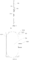
- an overlapping area of orthographic projections of the coil disk and the electromagnetic induction heating member 53 on the refrigerant heat exchanger 54 at least accounts for half of an area of an orthographic projection of the electromagnetic induction heating member 53 on the refrigerant heat exchanger 54.
- at least half of a peripheral area S2 of the electromagnetic induction heating member 53 falls within a peripheral orthographic projection area S1 of the coil disk.
- the above-mentioned orthographic projection refers to a forward projection on the reference plane.
- the overlapping area of the orthographic projections of the coil disk and the electromagnetic induction heating member 53 is not less than half of the orthographic projection area of the electromagnetic induction heating member 53, which may effectively reduce power consumption of the coil disk, increase an energy utilization rate, and reduce the magnetic flux leakage.
- the coil disk includes a coil support 521 and a wire body 522wound on the coil support 521, and two ends of the wire body 522 serve as wiring terminals 5221.
- the wire body 522 is wound on the coil support 521, such that the wire body 522 is conveniently wound, and the coil disk is conveniently mounted and positioned in the quick heating module 5.
- the coil disk may have other structural forms; for example, the coil disk may not include the coil support 521, the wire body 522 may be directly wound on the electromagnetic induction heating member 53, and even in some cases where the space is limited, the wire body 522 may be directly wound on the refrigerant heat exchanger 54.
- the wire body 522 is wound on the coil support 521 in a certain shape through a plurality of turns, and then the wire body 522 is shaped on the coil support 521 by a fastening operation, a binding operation, a plastic coating operation, or the like, so as to avoid wire looseness, or the like.
- the wire body 522 is made of an enameled wire, such that a cost is low.
- the wire body 522 is wound on the coil support 521 in a shape of a loop, a kidney, or the like, which is the simplest winding form.
- the coil support 521 is substantially rectangular
- the wire body 522 is wound into a flat annular coil
- the coil disk has a rectangular plate shape on the whole, and is provided on one side of the electromagnetic induction heating member 53, and therefore has a large surface superposed with the projection of the electromagnetic induction heating member 53, and does not occupy too much space.
- a wire slot 5212 is defined in the coil support 521, and the wire body 522 is clamped in the wire slot 5212, such that the wire body 522 may be fixed and restricted, which greatly reduces the probability of a wire looseness.; in addition, the wire body 522 is restrained by the wire slot 5212, such that the coil disk has a neater and more attractive appearance, and is not easy to tear and break during transportation and assembly.
- the wire slot 5212 has a shape consistent with the final shape of the wound wire body 522, and may be configured as an annular slot, a kidney-shaped slot, or the like.
- the coil support 521 is provided with a wire pressing hook 5213 configured to lock the wiring terminal 5221, such that the wiring terminal 5221 of the wire body 522 has a fixed position, which facilitates a wire connection.
- the coil disk includes a magnetic strip 523, and the magnetic strip 523 is provided on the coil support 521.
- the arrangement of the magnetic strip 523 may change a shape of the electromagnetic field at a periphery of the coil disk, such that more energy is concentrated on a side where the electromagnetic induction heating member 53 is provided, thereby improving an energy utilization efficiency.
- an extension line of the magnetic strip 523 is perpendicular to a tangent line of the wire body 522 at an intersection with the extension line. According to the features of the magnetic field of the coil, such an arrangement of the magnetic strip 523 facilitates expansion of an influence range of the magnetic strip 523, thereby further causing more energy to be concentrated on the side where the electromagnetic induction heating member 53 is provided.
- the coil support 521 is provided with a magnetic-strip fixing groove 5211 configured to limit the magnetic strip 523, such that the magnetic strip 523 can be conveniently assembled and positioned.
- the coil disk includes a voltage resistant sheet 524 provided on the coil holder 521 and located on a side of the wire body 522 facing the electromagnetic induction heating member 53.
- the arrangement of the voltage resistant sheet 524 further constrains the wire body 522, making the coil disk more flat on the whole.
- the voltage resistant sheet 524 is configured as a mica sheet or other similar material sheets.
- the coil disk and the electromagnetic induction heating member 53 have an optimal distance of 1-20 mm.
- the distance may be kept in various ways; a fixed-distance spacing block may be directly connected between the coil disk and the electromagnetic induction heating member 53, and the distance may also be kept indirectly.
- the refrigerant heat exchanger 54 and the coil disk are both connected to the outer protective member 50 to maintain the distance between the coil disk and the electromagnetic induction heating member 53.
- the coil disk includes a coil support 521, a wire body 522, a magnetic strip 523 and a voltage resistant sheet 524.
- the coil support 521 has a front surface and a rear surface
- FIG. 11 shows the front surface of the coil support 521
- FIG. 12 shows the rear surface of the coil support 521
- the wire body 522 is wound on the front surface of the coil support 521.
- the coil support 521 is configured as a nonmetallic support having a kidney shape or an oval shape.
- the front surface of the coil support 521 is provided with a wire slot 5212, the wire slot 5212 has a racetrack shape, a plurality of turns of wire slots are provided and arranged layer by layer from inside to outside, and each turn of wire slot 5212 has a kidney shape or an ellipse shape.
- the wire body 522 is provided along the wire slot 5212, such that the wire body 522 has a multi-turn form to form the coil.
- the coil support 521 is provided with a heat dissipation opening 5214, and a part of the heat dissipation opening 5214 is superposed with the wire slot 5212, and the arrangement of the heat dissipation opening 5214 may prevent the wire body 522 from being overheated.
- the heat dissipation opening 5214 is provided on the front surface of the coil support 521 and penetrates through the coil support 521 in a thickness direction.
- a plurality of heat dissipation openings 5214 are provided in an extending direction of the wire slot 5212, and each wire sloe 5212 is connected with the plural wire slots 5212 provided in inner and outer layers.
- the coil support 521 is provided with a wire pressing protrusion 5215 extending above the wire slot 5212, and the wire pressing protrusion 5215 is pressed on the wire body 522.
- a magnetic-strip fixing groove 5211 is defined in the rear surface of the coil support 521, and the magnetic strip 523 is fitted in the magnetic-strip fixing groove 5211.
- the coil support 521 is provided with a calendered protrusion 5216 extending above the magnetic-strip fixing groove 5211.
- a plurality of magnetic-strip fixing grooves 5211 are provided, and some of the magnetic-strip fixing grooves 5211 are provided in a length direction of the coil support 521, and some of the magnetic-strip fixing grooves 5211 are provided in a width direction of the coil support 521.
- a fool-proof block 5217 is provided on one side of the coil support 521 to prevent a reverse mounting phenomenon.
- the coil support 521 is provided with a wire pressing hook 5213 configured to press a wiring terminal 5221 of the wire body 522. As shown in FIG. 9 , two wire pressing hooks 5213 are provided.
- each fixing lug 5218 is provided with a support fixing hole 5219.
- the wire body 522 has to be made into a kidney-shaped or oval winding shape, and is limited and fixed by the plurality of wire pressing protrusions 5215 formed using a calendering process and added on the front surface of the coil support 521.
- the wiring terminal 5221 of the wire body 522 is buckled and pressed tightly by the wire pressing hook 5213.
- the plural magnetic strips 523 are provided in the magnetic-strip fixing grooves 5211 and limited and fixed by the plurality of calendered protrusions 5216 formed using a calendering process and added on the rear surface of the coil support 521.
- the magnetic strip 523 is fixed to the coil support 521 by a bonding connection.
- the voltage resistant sheet 524 is configured as a mica sheet with a certain thickness, has a shape fitted with the coil support 521, may also have a kidney shape or an oval shape, and is stuck to the front surface of the coil support 521.
- the quick heating module 5 includes a supporting plate 56, a heat insulation member 54, a refrigerant heat exchanger 54, a coil disk, and a fixed cover 5 which are sequentially provided.
- the heat insulation member 55 includes a first heat insulation member 551 and a second heat insulation member 552, the first heat insulation member 551 is provided between the supporting plate 56 and the refrigerant heat exchanger 54, and the second heat insulation member 552 is provided between the refrigerant heat exchanger 54 and the coil disk.
- the coil support 521 is fixed to four fixing columns 511 of the fixed cover 51 through the support fixing holes 5219 at the four corners, and the fixed cover 51 is fastened to a fixing hole 561 of the supporting plate 56 by a fixing clip 512. Then, external fixing screws sequentially penetrate through mounting holes 513 to be screwed into mounting threaded holes 562 of the supporting plate 56.
- An air conditioner 1000 according to an embodiment of the present application is described below with reference to FIGS. 5 and 19 .
- the air conditioner 1000 includes: a compressor 4 and the quick heating module 5 according to the above-mentioned embodiment of the present application, and the structure of the quick heating module 5 will not be described here.
- the refrigerant passage of the refrigerant heat exchanger 54 is connected with a discharge port of the compressor 4; that is, the quick heating module 5 is configured to quickly heat air discharged from the compressor 4.
- An exhaust side of the compressor 4 is provided with one quick heating module 5.
- the heating heat generated by the electromagnetic induction heating member 53 is transferred to the microchannel heat exchanger 540 by the alternating magnetic field generator 52, and the refrigerant comes into circulating and flowing contact with an inner wall of the refrigerant passage of the microchannel heat exchanger 540 to perform heat exchange and heat transfer, so as to obtain the heat quickly, thereby quickly increasing a temperature of the refrigerant.
- a heating time of the electromagnetic induction heating member 53 is set to be a period of time when the air conditioner is started, and a heating function of the electromagnetic induction heating member 53 is stopped after the air conditioner is started to generate heat stably, such that the air conditioner 1000 may be started to generate heat quickly in a low-temperature environment, so as to meet the user's low-temperature quick heating requirement.
- the quick heating module 5 may be connected between the compressor 4 and the outdoor heat exchanger 3, such that the temperature of the refrigerant discharged from the compressor may be higher, and a defrosting effect on the air-conditioner outdoor unit 100 may be better.
- the exhaust side of the compressor 4 is provided with the above-mentioned quick heating module 5, such that the air discharged from the compressor 4 is heated quickly, thus meeting the requirement of quick heating after the air conditioner 1000 is started in winter.
- the electromagnetic induction heating member 53 is provided on the refrigerant heat exchanger 54, and the alternating magnetic field generator 52 is provided for the electromagnetic induction heating member 53, such that the electromagnetic induction heating member 53 generates the heat under the action of electromagnetic induction to heat the refrigerant in the refrigerant heat exchanger 54, and the electricity may be separated from the refrigerant, thus reducing the process requirement and the machining difficulty of the refrigerant heat exchanger 54 and avoiding the electrical safety problems, such as the dry heating phenomenon of the electric heating portion, the line breakdown, or the like.
- the air conditioner 1000 is configured as a split type air conditioner, and includes an indoor unit and the air-conditioner outdoor unit 100, and the quick heating module 5 is provided in the air-conditioner outdoor unit 100.
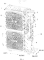
- an air-conditioner outdoor unit 100 includes an enclosure 1, a middle partition 2, an outdoor heat exchanger 3, an outdoor fan, a compressor 4, and a quick heating module 5.
- a mounting cavity is defined in the enclosure 1, and the middle partition 2 is provided in the mounting cavity and divides the mounting cavity into a left fan chamber 11 and a right mechanical chamber 12.
- a front panel 14 is provided on a front side of the mounting cavity, and an air outlet is defined on the front panel 14 corresponding to the fan chamber 11, and a mesh cover 13 covers the air outlet.
- the outdoor fan and the outdoor heat exchanger 3 are mounted in the fan chamber 11, and an air inlet is defined on a rear side of the outdoor heat exchanger 3.
- the compressor 4 is mounted at a lower portion of the mechanical chamber 12, and an electric control component 7 is mounted at an upper portion of the mechanical chamber 12 and controls electric components, such as the outdoor fan, the compressor, or the like, to be turned on and off.
- the terms “mounted”, “connected”, and “coupled” and the like are broadly used , and may be, for example, fixed connections, detachable connections, or integral connections; may also be mechanical or electrical connections; may also be direct connections or indirect connections via intervening structures; may also be inner communications of two elements.
- the above terms can be understood by those skilled in the art according to specific situations.
- the middle partition 2 here has certain strength, and is universal in the air-conditioner outdoor unit 100, and a shape and a size of the middle partition 2 are not limited, and may be adjusted according to a mounting space of the air-conditioner outdoor unit 100 and the mounting components required in the cavity.
- Heating cycle components of air conditioners such as the outdoor heat exchanger 3, the compressor 4, an indoor heat exchanger, a throttling element, or the like, and heating principles are well known in the art, so they will be not repeated herein.
- the electric control component 7 and the quick heating module 5 are both mounted on the middle partition 2, and the electric control component 7 is located above the quick heating module 5, and the quick heating module 5 is located above the compressor 4.
- the supporting plate 6 may be mounted on either side of the middle partition 2; that is, the quick heating module 5 may be located in the fan chamber 11 or the mechanical chamber 12, and an appropriate arrangement position may be selected as required.
- the quick heating module 5 includes the alternating magnetic field generator 52, the electromagnetic induction heating member 53 and the refrigerant heat exchanger 54, and the quick heating module 5 further includes the outer protective member 50 which is provided outside the alternating magnetic field generator 52, the electromagnetic induction heating member 53 and the refrigerant heat exchanger 54 for protection.
- the refrigerant heat exchanger 54 may be directly and fixedly connected to the middle partition 2, and the outer protective member 50 may only include the fixed cover 51, and the fixed cover 51 covers the alternating magnetic field generator 52, the electromagnetic induction heating member 53 and the refrigerant heat exchanger 54.
- the outer protective member 50 includes the fixed cover 51 and the supporting plate 56, and the refrigerant heat exchanger 54 is directly and fixedly connected to the supporting plate 5, and the fixed cover 51 is connected to the supporting plate 5 and covers the alternating magnetic field generator 52, the electromagnetic induction heating member 53 and the refrigerant heat exchanger 54.
Landscapes
- Engineering & Computer Science (AREA)
- Physics & Mathematics (AREA)
- Electromagnetism (AREA)
- Chemical & Material Sciences (AREA)
- Combustion & Propulsion (AREA)
- Mechanical Engineering (AREA)
- General Engineering & Computer Science (AREA)
- General Induction Heating (AREA)
Abstract
Description
- The present application is based on and claims priority to
Chinese Patent Application Serial Nos. 201920476599.4 201910277490.2 201920469021.6, all filed on April 08, 2019 - The present application relates to the field of heating apparatus technologies, and particularly to a quick heating module and an air conditioner.
- In a low-temperature environment, most air conditioners, due to their system limitations, are unable to increase heat of a refrigerant quickly in a starting stage, and thus, heating speed is low, and an indoor temperature is unable to be increased quickly, which can not meet a requirement of users for quick heating after starting the air conditioner in winter, and becomes a common problem of the air conditioner on the market.
- In order to solve the problem, a refrigerant heating structure is provided in a prior art, in which an electric heater is directly mounted in a copper tube to heat the refrigerant, so as to improve thermal efficiency of the refrigerant. However, the copper tube of this structure has an over complicated molding manufacturing technology, and a junction of the electric heater and the copper tube has a poor sealing reliability, and the electric heater may have a dry heating phenomenon under certain conditions. In addition, since an electric heating tube directly contacts the refrigerant, that is, electricity is not completely isolated from the refrigerant, electrical safety problems, such as the dry heating phenomenon of an electric heating portion, a line breakdown, or the like, are unable to be avoided.
- The present application seeks to solve at least one of the problems existing in the prior art. To this end, the present application provides a quick heating module for quickly heating a refrigerant.
- The present application aims to provide an air conditioner in which air discharged from a compressor may be quickly heated.
- A quick heating module according to an embodiment of the present application includes: a refrigerant heat exchanger defining a refrigerant passage therein; an electromagnetic induction heating member configured to heat the refrigerant heat exchanger; and an alternating magnetic field generator provided close to the electromagnetic induction heating member and emitting an alternating magnetic field to the electromagnetic induction heating member.
- In the quick heating module according to the embodiment of the present application, the electromagnetic induction heating member is provided on the refrigerant heat exchanger, and the alternating magnetic field generator is provided for the electromagnetic induction heating member, such that the electromagnetic induction heating member generates heat under the action of electromagnetic induction to heat a refrigerant in the refrigerant heat exchanger; with this refrigerant heating method, the refrigerant in a cooling apparatus or a heating apparatus may be quickly heated, and electricity may be separated from the refrigerant. Compared with a structure that an electric heating portion is directly provided in a refrigerant copper tube, a process requirement and a machining difficulty of the refrigerant heat exchanger are reduced, and electrical safety problems such as a dry heating phenomenon of the electric heating portion, a line breakdown, or the like, may be avoided.
- In some embodiments, the electromagnetic induction heating member is provided between the refrigerant heat exchanger and the alternating magnetic field generator, and the electromagnetic induction heating member directly contacts the refrigerant heat exchanger.
- In some embodiments, the refrigerant heat exchanger is configured as a microchannel heat exchanger.
- In some embodiments, the electromagnetic induction heating member is configured as a plate.
- Optionally, the electromagnetic induction heating member has a thickness less than or equal to 5 mm.
- In some embodiments, the electromagnetic induction heating member is connected to the refrigerant heat exchanger by a fastener.
- In some embodiments, the electromagnetic induction heating member and the refrigerant heat exchanger are provided with solder or a soldering flake therebetween and connected by welding.
- In some embodiments, the electromagnetic induction heating member and the refrigerant heat exchanger are provided with a heat conducting agent layer therebetween.
- In some embodiments, the alternating magnetic field generator and the electromagnetic induction heating member are provided with a heat insulation member therebetween.
- In some embodiments, the alternating magnetic field generator is configured as a coil disk.
- Optionally, the coil disk and the electromagnetic induction heating member have a distance of 1-20 mm therebetween.
- Specifically, an overlapping area of orthographic projections of the coil disk and the electromagnetic induction heating member on the refrigerant heat exchanger at least accounts for half of an area of an orthographic projection of the electromagnetic induction heating member on the refrigerant heat exchanger.
- Further, the coil disk includes: a coil support; and a wire body wound on the coil support, two ends of the wire body serving as wiring terminals.
- Still further, the coil disk further includes a magnetic strip, which is provided on the coil support.
- Optionally, an extension line of the magnetic strip is perpendicular to a tangent line of the wire body at an intersection with the extension line.
- Optionally, the coil support is provided with a magnetic-strip fixing groove configured to limit the magnetic strip.
- Optionally, the coil support defines a wire slot, and the wire body is clamped in the wire slot.
- Optionally, the coil support is provided with a wire pressing hook configured to lock the wiring terminal.
- Optionally, the coil support is substantially rectangular, and the wire body is wound into a flat annular coil.
- Optionally, the coil disk includes a voltage resistant sheet provided on the coil support and located on a side of the wire body facing the electromagnetic induction heating member.
- In some embodiments, the electromagnetic induction heating member is provided on the refrigerant heat exchanger, and the quick heating module further includes an outer protective member, and the refrigerant heat exchanger and the coil disk are connected to the outer protective member, so as to keep a distance between the coil disk and the electromagnetic induction heating member.
- An air conditioner according to an embodiment of the present application includes: a compressor; and the quick heating module according to the above-mentioned embodiment of the present application, the refrigerant passage of the refrigerant heat exchanger being connected with a discharge port of the compressor.
- In the air conditioner according to the embodiment of the present application, an exhaust side of the compressor is provided with the above-mentioned quick heating module, such that the air discharged from the compressor is heated quickly, thus meeting a requirement of quick heating after the air conditioner is started in winter. The electromagnetic induction heating member is provided on the refrigerant heat exchanger, and the alternating magnetic field generator is provided for the electromagnetic induction heating member, such that the electromagnetic induction heating member generates the heat under the action of electromagnetic induction to heat the refrigerant in the refrigerant heat exchanger, and the electricity may be separated from the refrigerant, thus reducing the process requirement and the machining difficulty of the refrigerant heat exchanger, and avoiding the electrical safety problems, such as the dry heating phenomenon of the electric heating portion, the line breakdown , or the like.
- Additional aspects and advantages of the present application will be given in part in the following descriptions, become apparent in part from the following descriptions, or be learned from the practice of the embodiments of the present application.
- The above and/or additional aspects and advantages of the present application will become apparent and more readily appreciated from the following descriptions made with reference to the drawings, in which:
-
FIG. 1 is a schematic diagram of assembly correspondence between a refrigerant heat exchanger and an electromagnetic induction heating member of a quick heating module according to an embodiment. -
FIG. 2 is a side view of the refrigerant heat exchanger and the electromagnetic induction heating member according to an embodiment. -
FIG. 3 is a top view of the quick heating module according to an embodiment. -
FIG. 4 is a side view of the quick heating module according to another embodiment. -
FIG. 5 is a schematic exploded diagram of the quick heating module according to another embodiment. -
FIG. 6 is a rear view of a coil disk of the quick heating module according to an embodiment. -
FIG. 7 is a side view of the coil disk of the quick heating module according to an embodiment. -
FIG. 8 is a front view of the coil disk of the quick heating module according to an embodiment. -
FIG. 9 is an exploded view of the coil disk of the quick heating module according to an embodiment. -
FIG. 10 is a front view of a coil support in the quick heating module according to an embodiment. -
FIG. 11 is a partial front view of the coil support in the quick heating module according to an embodiment. -
FIG. 12 is a partial rear view of the coil support in the quick heating module according to an embodiment. -
FIG. 13 is a schematic assembly diagram of the coil disk, the electromagnetic induction heating member and a microchannel heat exchanger according to an embodiment. -
FIG. 14 is an exploded view of the quick heating module according to an embodiment. -
FIG. 15 is a schematic diagram of an orthographic projection plane of the electromagnetic induction heating member on the refrigerant heat exchanger according to an embodiment. -
FIG. 16 is a schematic diagram of an orthographic projection plane of the coil disk on the refrigerant heat exchanger according to the embodiment shown inFIG. 15 . -
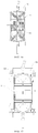
FIG. 17 is a front view of a structure of the quick heating module according to another embodiment. -
FIG. 18 is a side view of the structure of the quick heating module according to the embodiment shown inFIG. 17 . -
FIG. 19 is a perspective view of an air-conditioner outdoor unit according to an embodiment (with a component housing hidden). -
-
Air conditioner 1000; - air-conditioner
outdoor unit 100; -
enclosure 1;fan chamber 11;mechanical chamber 12;mesh cover 13;front panel 14;middle partition 2;outdoor heat exchanger 3;compressor 4;electric control component 7. -
Quick heating module 5; - outer
protective member 50; fixedcover 51; fixingcolumn 511; fixingclip 512; mountinghole 513; supportingplate 56; fixinghole 561; - alternating
magnetic field generator 52;coil support 521; magnetic-strip fixing groove 5211;wire slot 5212;wire pressing hook 5213;heat dissipation opening 5214;wire pressing protrusion 5215; calenderedprotrusion 5216; fool-proof block 5217; fixinglug 5218;support fixing hole 5219;wire body 522;wiring terminal 5221;magnetic strip 523; voltageresistant sheet 524;leg 525; - electromagnetic
induction heating member 53; heating-member viahole 531; heating-member escaping hole 532; heating-member fastener 533; -
refrigerant heat exchanger 54;microchannel heat exchanger 540; collectingpipe 541; inlet-outlet pipe 542;microchannel base plate 543; heat-exchanger threadedhole 545; heat-exchanger viahole 546; heat-exchanger fastener 547; -
heat insulation member 55; firstheat insulation member 551; secondheat insulation member 552. - Reference will be made in detail to embodiments of the present application, and the examples of the embodiments are illustrated in the drawings, wherein the same or similar elements and the elements having same or similar functions are denoted by like reference numerals throughout the descriptions. The embodiments described herein with reference to drawings are illustrative, and merely used to explain the present application. The embodiments shall not be construed to limit the present application.
- A
quick heating module 5 according to an embodiment of the present application will be described below with reference to the accompanying drawings, and thequick heating module 5 is used in a refrigerant circulation system, such as an air conditioner, a water heater, or the like. - The
quick heating module 5 according to the embodiment of the present application, as shown inFIGS. 1 and5 , includes: arefrigerant heat exchanger 54, an electromagneticinduction heating member 53 and an alternatingmagnetic field generator 52. Therefrigerant heat exchanger 54 has a refrigerant passage defined therein, and the electromagneticinduction heating member 53 is configured to heat therefrigerant heat exchanger 54, so as to heat a refrigerant flowing through the refrigerant passage, and the alternatingmagnetic field generator 52 is provided close to the electromagneticinduction heating member 53 and emits an alternating magnetic field to the electromagneticinduction heating member 53. - It may be understood that when the electromagnetic
induction heating member 53 is located in a changing magnetic field, an induced electromotive force is generated in the electromagneticinduction heating member 53 by electromagnetic induction. Since the electromagneticinduction heating member 53 has a resistance, a current may be generated in the electromagneticinduction heating member 53, and the distribution of the current in the electromagneticinduction heating member 53 is different along with a surface shape and magnetic flux distribution of the electromagneticinduction heating member 53, and an eddy current formed by a path of the current generates heat in the electromagneticinduction heating member 53, such that after the alternatingmagnetic field generator 52 generates an alternating magnetic field, and the electromagneticinduction heating member 53 may heat therefrigerant heat exchanger 54, so as to quickly heat the refrigerant in the refrigerant passage. - In this heating method, the alternating
magnetic field generator 52 is energized to impel the electromagneticinduction heating member 53 to generate heat, instead of concentrating a heat source at one point and then diffusing outwards by the heat source point, such that no heat concentration point exists on therefrigerant heat exchanger 54, and electrical safety problems, such as a dry heating phenomenon, a line breakdown, or the like, may be avoided. - In the
quick heating module 5 according to the embodiment of the present application, the electromagneticinduction heating member 53 is provided on therefrigerant heat exchanger 54, and the alternatingmagnetic field generator 52 is provided for the electromagneticinduction heating member 53, such that the electromagneticinduction heating member 53 generates heat under the action of electromagnetic induction to heat the refrigerant in therefrigerant heat exchanger 54; with this refrigerant heating method, the refrigerant in a cooling apparatus or a heating apparatus may be quickly heated. - In a prior art, an electric heater of a refrigerant heating structure is directly mounted in a copper tube to heat the refrigerant, and the refrigerant may be in an electricity contact state. In the
quick heating module 5 according to the embodiment of the present application, the alternatingmagnetic field generator 52 is only required to be energized to generate the alternating magnetic field, without direct electrification of therefrigerant heat exchanger 54, such that the electricity may be isolated from the refrigerant. Since an electric heating portion is not required to be directly buried in the refrigerant copper tube, there is no higher sealing requirement for therefrigerant heat exchanger 54, which reduces the process requirement and the machining difficulty of therefrigerant heat exchanger 54, and further avoids electrical safety problems, such as the dry heating phenomenon of the electric heating portion, the line breakdown, and the like. - In the embodiment of the present application, the electromagnetic
induction heating member 53 has various structural forms. - In some embodiments, as shown in
FIGS. 1 to 3 , the electromagneticinduction heating member 53 is configured as a plate, and fixedly mounted after being machined, such that the electromagneticinduction heating member 53 is quite easy to be machined and mounted. In some embodiments, at least a part of the electromagneticinduction heating member 53 has a strip shape, and the electromagneticinduction heating member 53 is inserted between adjacent refrigerant pipes, such that a heat exchange space may be fully used to dispose the electromagneticinduction heating member 53. - Optionally, the electromagnetic
induction heating member 53 has a thickness less than or equal to 5 mm, and the thickness thereof satisfies the relation: 0<t<=5 mm. The electromagneticinduction heating member 53 serves as both a heating member and a heat conductor, and the heat generated by the electromagneticinduction heating member 53 may be quickly conducted to the refrigerant passage of therefrigerant heat exchanger 54, and the electromagneticinduction heating member 53 is not required to store heat. The whole plate should not be too thick; on the one hand, an over-thick plate consumes too much heat, thus reducing a heat utilization efficiency, and on the other hand, the over-thick plate may increase a volume and a weight of the wholequick heating module 5. - Specifically, the electromagnetic
induction heating member 53 is configured as a component made of a magnetic conduction material; for example, the electromagneticinduction heating member 53 contains iron, nickel, iron oxide, chromium oxide, or the like. The magnetic conduction material capable of generating electromagnetic induction may be any material disclosed in the prior art, which is not limited herein. - More specifically, the electromagnetic
induction heating member 53 may be configured as a single-layer plate integrally formed of a magnetic conduction material, such as an iron plate, an iron oxide plate, or a chromium oxide plate. The electromagneticinduction heating member 53 may also be configured as a composite layer member, and at least one layer of the electromagneticinduction heating member 53 is configured as a magnetic conduction material layer, and other layers may be provided as required. - In other embodiments of the present application, the electromagnetic
induction heating member 53 may also be configured as a sprayed layer or a coating made of a magnetic conduction material. For example, a protection plate or a supporting plate, or the like, may be provided on a surface of therefrigerant heat exchanger 54, and the electromagneticinduction heating member 53 may be configured as a coating sprayed on a surface of the protection plate or the supporting plate. The electromagneticinduction heating member 53 is even configured as a coating sprayed on the surface of therefrigerant heat exchanger 54. When the electromagneticinduction heating member 53 is provided in this way, selection of a position and a shape thereof is more flexible, and the spraying form may enlarge a heated surface on therefrigerant heat exchanger 54. - In still other embodiments, a pipe wall of the refrigerant passage is made of a magnetic conduction material and forms the electromagnetic
induction heating member 53. For example, the pipes of therefrigerant heat exchanger 54 configured to circulate the refrigerant are made of magnetic conduction materials, such that the pipe wall of the refrigerant passage directly generates heat and heats the refrigerant under an alternating magnetic field, and the heat utilization efficiency may be further improved. - In the embodiment of the present application, a structure type of the
refrigerant heat exchanger 54 is not limited. Therefrigerant heat exchanger 54 may be configured as a plate heat exchanger, or even therefrigerant heat exchanger 54 may be formed of only one metal pipe, and a pipe cavity of the metal pipe forms the refrigerant passage. - In some embodiments, as shown in
FIGS. 1 and5 , therefrigerant heat exchanger 54 is configured as amicrochannel heat exchanger 540, and a type of which is not limited. Themicrochannel heat exchanger 540 is used for the refrigerant to flow through, such that the refrigerant flowing through themicrochannel heat exchanger 540 may be guided into a small streams, thus greatly increasing a specific surface area, and significantly improving a heating efficiency. In some embodiments, themicrochannel heat exchanger 540 includes a collectingpipe 541, and in some other embodiments, themicrochannel heat exchanger 540 includes a collectingpipe 541 and a plurality of flat pipes. - Specifically, the electromagnetic
induction heating member 53 may be provided on themicrochannel heat exchanger 540 in any one of the above-mentioned manners, which is not limited herein. In addition to the above-mentioned manner, at least a part of the electromagneticinduction heating member 53 may be inserted between two adjacent flat pipes, which is equivalent to the above description that the strip-shaped part of the electromagneticinduction heating member 53 is inserted between the adjacent refrigerant pipes. When the electromagneticinduction heating member 53 is provided corresponding to themicrochannel heat exchanger 540 in this way, various forms may be adopted, such that a surface space of themicrochannel heat exchanger 540 may be fully utilized. - Specifically, there are two collecting
pipes 541, which are provided on two opposite sides of themicrochannel heat exchanger 540. The electromagneticinduction heating member 53 is configured as a plate and provided on one side of themicrochannel heat exchanger 540. More specifically, an inlet-outlet pipe 542 is connected to each of the two collectingpipes 541, such that the refrigerant may flow into and out of the collecting pipe. - Optionally, the two collecting
pipes 541 are arranged in parallel. In some examples, themicrochannel heat exchanger 540 can be formed in various shapes, such as a groove shape, a square shape, or the like, and the shape of the electromagneticinduction heating member 53 should be adapted correspondingly. For example, when themicrochannel heat exchanger 540 is formed into a square tube shape, the electromagneticinduction heating member 53 may also be formed into a square tube shape, and at this point, the square tube of the electromagneticinduction heating member 53 may be fitted over the square tube of themicrochannel heat exchanger 540 or the square tube of themicrochannel heat exchanger 540 may be fitted over the square tube of the electromagneticinduction heating member 53. - When the
microchannel heat exchanger 540 includes the flat pipe connected to the collectingpipe 541, the flat pipe is provided along the shape of themicrochannel heat exchanger 540, and a plurality of parallel flat pipes or one sinuous flat pipe may be provided. - Optionally, the
microchannel heat exchanger 540 has a rectangular overall shape, and the electromagneticinduction heating member 53 is configured as a rectangular plate. - Further, as shown in
FIGS. 1 and14 , themicrochannel heat exchanger 540 further includes amicrochannel base plate 543, which is located between the two collectingpipes 541, and the electromagneticinduction heating member 53 is connected to themicrochannel base plate 543. Thus, thequick heating module 5 is flat as a whole, which facilitates the quick heating module to be mounted in a narrow space. - In the embodiment of the present application, various connection modes may be adopted between the electromagnetic
induction heating member 53 and therefrigerant heat exchanger 54. For example, the electromagneticinduction heating member 53 is connected to therefrigerant heat exchanger 54 by a fastener, thus guaranteeing a tight connection therebetween. For example, solder or a soldering flake is provided between the electromagneticinduction heating member 53 and therefrigerant heat exchanger 54, and a welding connection is performed, thus guaranteeing a tight and firm connection therebetween. - In some embodiments, a heat conducting agent layer is provided between the electromagnetic
induction heating member 53 and therefrigerant heat exchanger 54 to improve a heat transfer efficiency. - In some embodiments, the following three modes are provided:
- First mode: the electromagnetic
induction heating member 53 is connected to therefrigerant heat exchanger 54 by a plurality of heating-member fasteners 533. - Second mode: contact surfaces of the electromagnetic
induction heating member 53 and therefrigerant heat exchanger 54 are coated with a heat conducting agent (heat conducting silicone grease, a heat conducting sheet, or the like), and then, the electromagneticinduction heating member 53 is connected with therefrigerant heat exchanger 54 by a heating-member fastener 533. - Third mode: contact surfaces of the electromagnetic
induction heating member 53 and therefrigerant heat exchanger 54 are welded, fused and in tight contact by filling solder, and the whole contact surfaces are evenly coated with the solder. - Optionally, as shown in
FIGS. 1 to 3 , a plurality of heat-exchanger threadedholes 545 are defined in themicrochannel heat exchanger 540, and heating-member viaholes 531 are correspondingly defined in the electromagneticinduction heating member 53, and the electromagneticinduction heating member 53 is connected to the heat-exchanger threadedholes 545 by inserting the plurality of heating-member fasteners 533 through the heating-member viaholes 531, such that the electromagneticinduction heating member 53 and therefrigerant heat exchanger 54 are connected into a whole. - Further, a plurality of heat-exchanger via
holes 546 are defined in themicrochannel heat exchanger 540, and themicrochannel heat exchanger 540 is connected into a supporting structure by inserting a plurality of heat-exchanger fasteners 547 through the heat-exchanger viaholes 546. Optionally, the electromagneticinduction heating member 53 is provided with heating-member escaping holes 532 corresponding to the plurality of heat-exchanger fasteners 547 to avoid affecting a mounting operation of the heat-exchanger fasteners 547. - In some embodiments, as shown in
FIGS. 4 ,5 and14 , the electromagneticinduction heating member 53 is provided between therefrigerant heat exchanger 54 and the alternatingmagnetic field generator 52, and directly contacts therefrigerant heat exchanger 54, thus reducing a range of the alternating magnetic field and unnecessary energy consumption. - Optionally, as shown in
FIG. 15 , an area of a projection of the electromagneticinduction heating member 53 on therefrigerant heat exchanger 54 is greater than half of an area of therefrigerant heat exchanger 54, thus effectively ensuring that the heat absorbed by the electromagneticinduction heating member 53 is transferred to therefrigerant heat exchanger 54. - In some embodiments, as shown in
FIGS. 5 and14 , aheat insulation member 55 is provided between the alternatingmagnetic field generator 52 and the electromagneticinduction heating member 53, so as to prevent the heat generated by the electromagneticinduction heating member 53 from being radiated to the alternatingmagnetic field generator 52, thereby avoiding a fused phenomenon, ignition, disconnection, or the like, of the alternatingmagnetic field generator 52 after heated. In addition, aheat insulation member 55 is provided between the alternatingmagnetic field generator 52 and the electromagneticinduction heating member 53, thus reducing heat loss, and improving a refrigerant heating efficiency. - Optionally, a
heat insulation member 55 is also provided outside therefrigerant heat exchanger 54 to reduce heat loss. - Specifically, as shown in
FIG. 14 , theheat insulation member 55 includes a firstheat insulation member 551 and a secondheat insulation member 552, the firstheat insulation member 551 is provided between therefrigerant heat exchanger 54 and the supporting structure, and the secondheat insulation member 552 is provided between the alternatingmagnetic field generator 52 and the electromagneticinduction heating member 53. - In the specific examples shown in
FIGS. 5 and14 , thequick heating module 5 includes an outerprotective member 50 provided outside themicrochannel heat exchanger 540, the electromagneticinduction heating member 53 and the alternatingmagnetic field generator 52 for protection. Specifically, the outerprotective member 50 includes a fixedcover 51 and a supportingplate 56, themicrochannel heat exchanger 540 is connected to the supportingplate 56, and the fixedcover 51 is connected to the supportingplate 56 and covers themicrochannel heat exchanger 540. - The second
heat insulation member 552 is provided between the electromagneticinduction heating member 53 and the alternatingmagnetic field generator 52 to prevent the high-temperature electromagneticinduction heating member 53 from radiating heat to the alternatingmagnetic field generator 52, and the secondheat insulation member 552 tightly contacts the electromagneticinduction heating member 53 to prevent the electromagneticinduction heating member 53 from losing heat; the firstheat insulation member 551 is provided between themicrochannel base plate 543 of themicrochannel heat exchanger 540 and the supportingplate 56 to prevent the heat of themicrochannel heat exchanger 540 from contacting the supportingplate 56 and being transferred to a metal object, resulting in heat loss. - As shown in
FIG. 14 , themicrochannel heat exchanger 540 is secured to the supportingplate 56 by inserting the heat-exchanger fastener 547 through the heat-exchanger viahole 546; the alternatingmagnetic field generator 52 is fixed to the fixedcover 51 which is fixed to the supportingplate 56, and at this point, the electromagneticinduction heating member 53, themicrochannel heat exchanger 540 and the alternatingmagnetic field generator 52 have fixed relative positions. - In the embodiment of the present application, the structure of the alternating
magnetic field generator 52 may be implemented in various ways known in the prior art. For example, in some examples, a permanent magnet is driven to rotate by a mechanical structure, such that the permanent magnet generates an alternating magnetic field on the electromagneticinduction heating member 53. For another example, in some examples, a coil is used instead of the permanent magnet to rotate, such that a magnetic field generated by the coil is converted into an alternating magnetic field on the electromagneticinduction heating member 53. In still other examples, a coil is combined with a permanent magnet to increase the intensity and stability of the alternating magnetic field. - In some embodiments, as shown in
FIGS. 5, 6 , and13 , the alternatingmagnetic field generator 52 is configured as a coil disk, and the principle of generating an alternating magnetic field by the coil disk is known in the prior art and will not be repeated herein. When the coil disk generates an alternating current, the electromagneticinduction heating member 53 generates heat, such that the magnetic density is high, and the alternating magnetic field is quite stable. Therefrigerant heat exchanger 54 may adopt a structure of any heat exchanger known in the prior art, and the arrangement of the coil disk in most solutions of the present application may not influence the structure of therefrigerant heat exchanger 54; that is, a manufacturer may directly purchase a heat exchanger known in the market, and can assemble thequick heating module 5 by mounting the coil disk and the electromagneticinduction heating member 53 on the heat exchanger. - Specifically, the coil disk is provided on one side of the
refrigerant heat exchanger 54, and when thequick heating module 5 operates, the coil disk remains fixed, such that thequick heating module 5 is quite easy to assemble. - In some embodiments, in order to ensure that the magnetic field generated at the electromagnetic
induction heating member 53 has a sufficiently large intensity after the coil disk is powered on, the coil disk and the electromagneticinduction heating member 53 have a distance of 1-20 mm. It may be understood that if the coil disk is over close to the electromagneticinduction heating member 53, the heat generated by the electromagneticinduction heating member 53 tends to be radiated to the coil disk, thereby causing a certain hidden danger to a use safety of the coil disk. If the coil disk is too far from the electromagneticinduction heating member 53, a magnetic flux is prone to leakage, and an electromagnetic conversion utilization rate is lower. - In some embodiments, as shown in
FIG. 16 , an overlapping area of orthographic projections of the coil disk and the electromagneticinduction heating member 53 on therefrigerant heat exchanger 54 at least accounts for half of an area of an orthographic projection of the electromagneticinduction heating member 53 on therefrigerant heat exchanger 54. As shown inFIGS. 15 and16 , at least half of a peripheral area S2 of the electromagneticinduction heating member 53 falls within a peripheral orthographic projection area S1 of the coil disk. Here, with an extension plane of therefrigerant heat exchanger 54 as a reference plane, the above-mentioned orthographic projection refers to a forward projection on the reference plane. - It may be understood that, under the premise of generating a same density of magnetic flux lines, the less the overlapping area of the orthographic projections of the coil disk and the electromagnetic
induction heating member 53, the greater the power required by the coil disk. Since the electromagneticinduction heating member 53 is configured to transfer heat to therefrigerant heat exchanger 54, with the extension plane of therefrigerant heat exchanger 54 as the reference plane, the overlapping area of the orthographic projections of the coil disk and the electromagneticinduction heating member 53 is not less than half of the orthographic projection area of the electromagneticinduction heating member 53, which may effectively reduce power consumption of the coil disk, increase an energy utilization rate, and reduce the magnetic flux leakage. - In some embodiments, as shown in
FIGS. 6 to 9 , the coil disk includes acoil support 521 and a wire body 522wound on thecoil support 521, and two ends of thewire body 522 serve aswiring terminals 5221. Here, thewire body 522 is wound on thecoil support 521, such that thewire body 522 is conveniently wound, and the coil disk is conveniently mounted and positioned in thequick heating module 5. - Certainly, in other embodiments of the present application, the coil disk may have other structural forms; for example, the coil disk may not include the
coil support 521, thewire body 522 may be directly wound on the electromagneticinduction heating member 53, and even in some cases where the space is limited, thewire body 522 may be directly wound on therefrigerant heat exchanger 54. - In some embodiments, the
wire body 522 is wound on thecoil support 521 in a certain shape through a plurality of turns, and then thewire body 522 is shaped on thecoil support 521 by a fastening operation, a binding operation, a plastic coating operation, or the like, so as to avoid wire looseness, or the like. - Optionally, the
wire body 522 is made of an enameled wire, such that a cost is low. Thewire body 522 is wound on thecoil support 521 in a shape of a loop, a kidney, or the like, which is the simplest winding form. - In a specific example, as shown in
FIGS. 8 to 10 , thecoil support 521 is substantially rectangular, thewire body 522 is wound into a flat annular coil, and the coil disk has a rectangular plate shape on the whole, and is provided on one side of the electromagneticinduction heating member 53, and therefore has a large surface superposed with the projection of the electromagneticinduction heating member 53, and does not occupy too much space. - Optionally, as shown in
FIGS. 9 to 11 , awire slot 5212 is defined in thecoil support 521, and thewire body 522 is clamped in thewire slot 5212, such that thewire body 522 may be fixed and restricted, which greatly reduces the probability of a wire looseness.; in addition, thewire body 522 is restrained by thewire slot 5212, such that the coil disk has a neater and more attractive appearance, and is not easy to tear and break during transportation and assembly. Specifically, thewire slot 5212 has a shape consistent with the final shape of thewound wire body 522, and may be configured as an annular slot, a kidney-shaped slot, or the like. - Optionally, the
coil support 521 is provided with a wirepressing hook 5213 configured to lock thewiring terminal 5221, such that thewiring terminal 5221 of thewire body 522 has a fixed position, which facilitates a wire connection. - In some embodiments, as shown in
FIG. 9 , the coil disk includes amagnetic strip 523, and themagnetic strip 523 is provided on thecoil support 521. The arrangement of themagnetic strip 523 may change a shape of the electromagnetic field at a periphery of the coil disk, such that more energy is concentrated on a side where the electromagneticinduction heating member 53 is provided, thereby improving an energy utilization efficiency. - Further, an extension line of the
magnetic strip 523 is perpendicular to a tangent line of thewire body 522 at an intersection with the extension line. According to the features of the magnetic field of the coil, such an arrangement of themagnetic strip 523 facilitates expansion of an influence range of themagnetic strip 523, thereby further causing more energy to be concentrated on the side where the electromagneticinduction heating member 53 is provided. - Optionally, as shown in
FIGS. 9 and12 , thecoil support 521 is provided with a magnetic-strip fixing groove 5211 configured to limit themagnetic strip 523, such that themagnetic strip 523 can be conveniently assembled and positioned. - In some embodiments, as shown in
FIGS. 8 and9 , the coil disk includes a voltageresistant sheet 524 provided on thecoil holder 521 and located on a side of thewire body 522 facing the electromagneticinduction heating member 53. The arrangement of the voltageresistant sheet 524 further constrains thewire body 522, making the coil disk more flat on the whole. Optionally, the voltageresistant sheet 524 is configured as a mica sheet or other similar material sheets. - In the embodiment of the present application, in order to guarantee the use safety of the coil disk and reduce the magnetic flux leakage, the coil disk and the electromagnetic
induction heating member 53 have an optimal distance of 1-20 mm. The distance may be kept in various ways; a fixed-distance spacing block may be directly connected between the coil disk and the electromagneticinduction heating member 53, and the distance may also be kept indirectly. Specifically, therefrigerant heat exchanger 54 and the coil disk are both connected to the outerprotective member 50 to maintain the distance between the coil disk and the electromagneticinduction heating member 53. - A specific structure of the
quick heating module 5 and a manner of maintaining the above-described distance according to one embodiment will be described below with reference toFIGS. 6 to 18 . - As shown in
FIG. 9 , the coil disk includes acoil support 521, awire body 522, amagnetic strip 523 and a voltageresistant sheet 524. - As shown in
FIGS. 10 to 12 , thecoil support 521 has a front surface and a rear surface,FIG. 11 shows the front surface of thecoil support 521,FIG. 12 shows the rear surface of thecoil support 521, and thewire body 522 is wound on the front surface of thecoil support 521. - Specifically, as shown in
FIGS. 10 and11 , thecoil support 521 is configured as a nonmetallic support having a kidney shape or an oval shape. The front surface of thecoil support 521 is provided with awire slot 5212, thewire slot 5212 has a racetrack shape, a plurality of turns of wire slots are provided and arranged layer by layer from inside to outside, and each turn ofwire slot 5212 has a kidney shape or an ellipse shape. Thewire body 522 is provided along thewire slot 5212, such that thewire body 522 has a multi-turn form to form the coil. - Specifically, as shown in
FIGS. 10 and11 , thecoil support 521 is provided with aheat dissipation opening 5214, and a part of theheat dissipation opening 5214 is superposed with thewire slot 5212, and the arrangement of theheat dissipation opening 5214 may prevent thewire body 522 from being overheated. Specifically, theheat dissipation opening 5214 is provided on the front surface of thecoil support 521 and penetrates through thecoil support 521 in a thickness direction. Advantageously, a plurality ofheat dissipation openings 5214 are provided in an extending direction of thewire slot 5212, and eachwire sloe 5212 is connected with theplural wire slots 5212 provided in inner and outer layers. - More specifically, as shown in
FIG. 11 , thecoil support 521 is provided with awire pressing protrusion 5215 extending above thewire slot 5212, and thewire pressing protrusion 5215 is pressed on thewire body 522. - In addition, as shown in
FIG. 12 , a magnetic-strip fixing groove 5211 is defined in the rear surface of thecoil support 521, and themagnetic strip 523 is fitted in the magnetic-strip fixing groove 5211. Thecoil support 521 is provided with acalendered protrusion 5216 extending above the magnetic-strip fixing groove 5211. - Specifically, a plurality of magnetic-
strip fixing grooves 5211 are provided, and some of the magnetic-strip fixing grooves 5211 are provided in a length direction of thecoil support 521, and some of the magnetic-strip fixing grooves 5211 are provided in a width direction of thecoil support 521. - More specifically, as shown in
FIG. 10 , a fool-proof block 5217 is provided on one side of thecoil support 521 to prevent a reverse mounting phenomenon. - Specifically, the
coil support 521 is provided with a wirepressing hook 5213 configured to press awiring terminal 5221 of thewire body 522. As shown inFIG. 9 , twowire pressing hooks 5213 are provided. - Specifically, as shown in
FIG. 10 , four corners of thecoil support 521 are provided with fixinglugs 5218, and each fixinglug 5218 is provided with asupport fixing hole 5219. - As shown in
FIG. 9 , to adapt to thewire slot 5212, thewire body 522 has to be made into a kidney-shaped or oval winding shape, and is limited and fixed by the plurality ofwire pressing protrusions 5215 formed using a calendering process and added on the front surface of thecoil support 521. Thewiring terminal 5221 of thewire body 522 is buckled and pressed tightly by thewire pressing hook 5213. - The plural
magnetic strips 523 are provided in the magnetic-strip fixing grooves 5211 and limited and fixed by the plurality ofcalendered protrusions 5216 formed using a calendering process and added on the rear surface of thecoil support 521. Themagnetic strip 523 is fixed to thecoil support 521 by a bonding connection. - The voltage
resistant sheet 524 is configured as a mica sheet with a certain thickness, has a shape fitted with thecoil support 521, may also have a kidney shape or an oval shape, and is stuck to the front surface of thecoil support 521. - As shown in
FIGS. 13 and14 , thequick heating module 5 includes a supportingplate 56, aheat insulation member 54, arefrigerant heat exchanger 54, a coil disk, and afixed cover 5 which are sequentially provided. Theheat insulation member 55 includes a firstheat insulation member 551 and a secondheat insulation member 552, the firstheat insulation member 551 is provided between the supportingplate 56 and therefrigerant heat exchanger 54, and the secondheat insulation member 552 is provided between therefrigerant heat exchanger 54 and the coil disk. - The coil disk and the plate-shaped
refrigerant heat exchanger 54 have an inter-disk distance h=1-20 mm which has the following implementations. - First implementation: as shown in
FIG. 14 , thecoil support 521 is fixed to four fixingcolumns 511 of the fixedcover 51 through thesupport fixing holes 5219 at the four corners, and the fixedcover 51 is fastened to a fixinghole 561 of the supportingplate 56 by a fixingclip 512. Then, external fixing screws sequentially penetrate through mountingholes 513 to be screwed into mounting threadedholes 562 of the supportingplate 56. - The
refrigerant heat exchanger 54 is directly screwed on the supportingplate 56, such that therefrigerant heat exchanger 54, the electromagneticinduction heating member 53 and the coil disk have fixed distances, and the coil disk and the plate-shapedrefrigerant heat exchanger 54 have an inter-disk distance h=1-20 mm. - Second implementation: as shown in
FIGS. 17 and18 ,legs 525 are provided on two sides of the coil disk, and after the electromagneticinduction heating member 53 is fastened to therefrigerant heat exchanger 54, the coil disk is fastened to therefrigerant heat exchanger 54 by theleg 525, such that the coil disk and the plate-shapedrefrigerant heat exchanger 54 have an inter-disk distance h=1-20 mm. - An
air conditioner 1000 according to an embodiment of the present application is described below with reference toFIGS. 5 and19 . - The
air conditioner 1000 according to the embodiment of the present application, as shown inFIG. 19 , includes: acompressor 4 and thequick heating module 5 according to the above-mentioned embodiment of the present application, and the structure of thequick heating module 5 will not be described here. The refrigerant passage of therefrigerant heat exchanger 54 is connected with a discharge port of thecompressor 4; that is, thequick heating module 5 is configured to quickly heat air discharged from thecompressor 4. - Other configurations (for example, the
compressor 4, an outdoor heat exchanger, or the like) and operations of theair conditioner 1000 according to the embodiment of the present application are known to those skilled in the art and will not be described in detail herein. - An exhaust side of the
compressor 4 is provided with onequick heating module 5. The heating heat generated by the electromagneticinduction heating member 53 is transferred to themicrochannel heat exchanger 540 by the alternatingmagnetic field generator 52, and the refrigerant comes into circulating and flowing contact with an inner wall of the refrigerant passage of themicrochannel heat exchanger 540 to perform heat exchange and heat transfer, so as to obtain the heat quickly, thereby quickly increasing a temperature of the refrigerant. - Specifically, a heating time of the electromagnetic
induction heating member 53 is set to be a period of time when the air conditioner is started, and a heating function of the electromagneticinduction heating member 53 is stopped after the air conditioner is started to generate heat stably, such that theair conditioner 1000 may be started to generate heat quickly in a low-temperature environment, so as to meet the user's low-temperature quick heating requirement. - In addition, when an air-conditioner
outdoor unit 100 is required to operate in a defrosting mode, thequick heating module 5 may be connected between thecompressor 4 and theoutdoor heat exchanger 3, such that the temperature of the refrigerant discharged from the compressor may be higher, and a defrosting effect on the air-conditioneroutdoor unit 100 may be better. - In this way, not only the heating function of the refrigerant, uniform heating and simple processing technology are achieved, but also the complete isolation of electricity from the refrigerant is realized, thereby realizing the quick heating effect when the air conditioner is started in a low-temperature environment.
- In the
air conditioner 1000 according to the embodiment of the present application, the exhaust side of thecompressor 4 is provided with the above-mentionedquick heating module 5, such that the air discharged from thecompressor 4 is heated quickly, thus meeting the requirement of quick heating after theair conditioner 1000 is started in winter. The electromagneticinduction heating member 53 is provided on therefrigerant heat exchanger 54, and the alternatingmagnetic field generator 52 is provided for the electromagneticinduction heating member 53, such that the electromagneticinduction heating member 53 generates the heat under the action of electromagnetic induction to heat the refrigerant in therefrigerant heat exchanger 54, and the electricity may be separated from the refrigerant, thus reducing the process requirement and the machining difficulty of therefrigerant heat exchanger 54 and avoiding the electrical safety problems, such as the dry heating phenomenon of the electric heating portion, the line breakdown, or the like. - In an embodiment, the
air conditioner 1000 is configured as a split type air conditioner, and includes an indoor unit and the air-conditioneroutdoor unit 100, and thequick heating module 5 is provided in the air-conditioneroutdoor unit 100. As shown inFIG. 19 , an air-conditioneroutdoor unit 100 includes anenclosure 1, amiddle partition 2, anoutdoor heat exchanger 3, an outdoor fan, acompressor 4, and aquick heating module 5. - A mounting cavity is defined in the
enclosure 1, and themiddle partition 2 is provided in the mounting cavity and divides the mounting cavity into aleft fan chamber 11 and a rightmechanical chamber 12. Afront panel 14 is provided on a front side of the mounting cavity, and an air outlet is defined on thefront panel 14 corresponding to thefan chamber 11, and amesh cover 13 covers the air outlet. The outdoor fan and theoutdoor heat exchanger 3 are mounted in thefan chamber 11, and an air inlet is defined on a rear side of theoutdoor heat exchanger 3. Thecompressor 4 is mounted at a lower portion of themechanical chamber 12, and anelectric control component 7 is mounted at an upper portion of themechanical chamber 12 and controls electric components, such as the outdoor fan, the compressor, or the like, to be turned on and off. - In descriptions of the present application, it should be understood that, directions or positional relationships indicated by terms "length", "width", "thickness", "upper", "lower", "front", "rear", "left", "right", "top", "bottom", "inner", "outer" etc. are based on orientations or positional relationships shown in the accompanying drawings, and they are used only for describing the present application and for description simplicity, but do not indicate or imply that an indicated device or element must have a specific orientation or be constructed and operated in a specific orientation. Therefore, it cannot be understood as a limitation on the present application. Furthermore, the feature defined with "first" and "second" may include one or more of this feature explicitly or implicitly. In the description of the present application, "a plurality of' means two or more unless otherwise stated.
- In the description of the present application, it should be noted that unless specified or limited otherwise, the terms "mounted", "connected", and "coupled" and the like are broadly used , and may be, for example, fixed connections, detachable connections, or integral connections; may also be mechanical or electrical connections; may also be direct connections or indirect connections via intervening structures; may also be inner communications of two elements. The above terms can be understood by those skilled in the art according to specific situations.
- The
middle partition 2 here has certain strength, and is universal in the air-conditioneroutdoor unit 100, and a shape and a size of themiddle partition 2 are not limited, and may be adjusted according to a mounting space of the air-conditioneroutdoor unit 100 and the mounting components required in the cavity. Heating cycle components of air conditioners, such as theoutdoor heat exchanger 3, thecompressor 4, an indoor heat exchanger, a throttling element, or the like, and heating principles are well known in the art, so they will be not repeated herein. - The
electric control component 7 and thequick heating module 5 are both mounted on themiddle partition 2, and theelectric control component 7 is located above thequick heating module 5, and thequick heating module 5 is located above thecompressor 4. It should be noted that the supporting plate 6 may be mounted on either side of themiddle partition 2; that is, thequick heating module 5 may be located in thefan chamber 11 or themechanical chamber 12, and an appropriate arrangement position may be selected as required. - The
quick heating module 5 includes the alternatingmagnetic field generator 52, the electromagneticinduction heating member 53 and therefrigerant heat exchanger 54, and thequick heating module 5 further includes the outerprotective member 50 which is provided outside the alternatingmagnetic field generator 52, the electromagneticinduction heating member 53 and therefrigerant heat exchanger 54 for protection. - Specifically, the
refrigerant heat exchanger 54 may be directly and fixedly connected to themiddle partition 2, and the outerprotective member 50 may only include the fixedcover 51, and the fixedcover 51 covers the alternatingmagnetic field generator 52, the electromagneticinduction heating member 53 and therefrigerant heat exchanger 54. Or the outerprotective member 50 includes the fixedcover 51 and the supportingplate 56, and therefrigerant heat exchanger 54 is directly and fixedly connected to the supportingplate 5, and the fixedcover 51 is connected to the supportingplate 5 and covers the alternatingmagnetic field generator 52, the electromagneticinduction heating member 53 and therefrigerant heat exchanger 54. - In the description of the present specification, reference to "embodiments", and "examples" mean that a particular feature, structure, material, or characteristic described in connection with the embodiment or example are included in at least one embodiment or example of the present application. In the specification, the schematic expressions to the above-mentioned terms are not necessarily referring to the same embodiment or example. Furthermore, the described particular features, structures, materials, or characteristics may be combined in any suitable manner in one or more embodiments or examples.
- Although embodiments of the present application have been shown and illustrated, it shall be understood by those skilled in the art that various changes, modifications, alternatives and variants without departing from the principle and idea of the present application are acceptable. The scope of the present application is defined by the claims and its equivalents.
Claims (22)
- A quick heating module, comprising:a refrigerant heat exchanger defining a refrigerant passage therein;an electromagnetic induction heating member configured to heat the refrigerant heat exchanger; andan alternating magnetic field generator provided close to the electromagnetic induction heating member and emitting an alternating magnetic field to the electromagnetic induction heating member.
- The quick heating module according to claim 1, wherein the electromagnetic induction heating member is provided between the refrigerant heat exchanger and the alternating magnetic field generator, and the electromagnetic induction heating member directly contacts the refrigerant heat exchanger.
- The quick heating module according to claim 1 or 2, wherein the refrigerant heat exchanger is configured as a microchannel heat exchanger.
- The quick heating module according to any one of claims 1 to 3, wherein the electromagnetic induction heating member is configured as a plate.
- The quick heating module according to claim 4, wherein the electromagnetic induction heating member has a thickness less than or equal to 5 mm.
- The quick heating module according to any one of claims 1 to 5, wherein the electromagnetic induction heating member is connected to the refrigerant heat exchanger by a fastener.
- The quick heating module according to any one of claims 1 to 6, wherein the electromagnetic induction heating member and the refrigerant heat exchanger are provided with solder or a soldering flake therebetween and connected by welding.
- The quick heating module according to any one of claims 1 to 7, wherein the electromagnetic induction heating member and the refrigerant heat exchanger are provided with a heat conducting agent layer therebetween.
- The quick heating module according to any one of claims 1 to 8, wherein the alternating magnetic field generator and the electromagnetic induction heating member are provided with a heat insulation member therebetween.
- The quick heating module according to any one of claims 1 to 9, wherein the alternating magnetic field generator is configured as a coil disk.
- The quick heating module according to claim 10, wherein the coil disk and the electromagnetic induction heating member have a distance of 1-20 mm therebetween.
- The quick heating module according to claim 10 or 11, wherein an overlapping area of orthographic projections of the coil disk and the electromagnetic induction heating member on the refrigerant heat exchanger at least accounts for half of an area of an orthographic projection of the electromagnetic induction heating member on the refrigerant heat exchanger.
- The quick heating module according to any one of claims 10 to 12, wherein the coil disk comprises:a coil support; anda wire body wound on the coil support, two ends of the wire body serving as wiring terminals.
- The quick heating module according to claim 13, wherein the coil disk further comprises a magnetic strip, and the magnetic strip is provided on the coil support.
- The quick heating module according to claim 14, wherein an extension line of the magnetic strip is perpendicular to a tangent line of the wire body at an intersection with the extension line.
- The quick heating module according to claim 14, wherein the coil support is provided with a magnetic-strip fixing groove configured to limit the magnetic strip.
- The quick heating module according to claim 13, wherein the coil support defines a wire slot, and the wire body is clamped in the wire slot.
- The quick heating module according to claim 13, wherein the coil support is provided with a wire pressing hook configured to lock the wiring terminal.
- The quick heating module according to claim 13, wherein the coil support is substantially rectangular, and the wire body is wound into a flat annular coil.
- The quick heating module according to claim 13, wherein the coil disk comprises a voltage resistant sheet provided on the coil support and located on a side of the wire body facing the electromagnetic induction heating member.
- The quick heating module according to claim 11, wherein the electromagnetic induction heating member is provided on the refrigerant heat exchanger, the quick heating module further comprises an outer protective member, and the refrigerant heat exchanger and the coil disk are connected to the outer protective member, so as to keep a distance between the coil disk and the electromagnetic induction heating member.
- An air conditioner, comprising: a compressor; and a quick heating module according to any one of claims 1 to 21, the refrigerant passage of the refrigerant heat exchanger being connected with a discharge port of the compressor.
Applications Claiming Priority (4)
| Application Number | Priority Date | Filing Date | Title |
|---|---|---|---|
| CN201920469021.6U CN209861205U (en) | 2019-04-08 | 2019-04-08 | Fast heating module and air conditioner |
| CN201910277490.2A CN109982465A (en) | 2019-04-08 | 2019-04-08 | Rapid heat module and air conditioner |
| CN201920476599.4U CN209861206U (en) | 2019-04-08 | 2019-04-08 | Quick heating module and air conditioner |
| PCT/CN2020/080948 WO2020207240A1 (en) | 2019-04-08 | 2020-03-24 | Quick heating module and air conditioner |
Publications (3)
| Publication Number | Publication Date |
|---|---|
| EP3927112A1 true EP3927112A1 (en) | 2021-12-22 |
| EP3927112A4 EP3927112A4 (en) | 2022-04-20 |
| EP3927112B1 EP3927112B1 (en) | 2025-12-10 |
Family
ID=72750892
Family Applications (1)
| Application Number | Title | Priority Date | Filing Date |
|---|---|---|---|
| EP20787252.4A Active EP3927112B1 (en) | 2019-04-08 | 2020-03-24 | Quick heating module and air conditioner |
Country Status (2)
| Country | Link |
|---|---|
| EP (1) | EP3927112B1 (en) |
| WO (1) | WO2020207240A1 (en) |
Family Cites Families (13)
| Publication number | Priority date | Publication date | Assignee | Title |
|---|---|---|---|---|
| US5334819A (en) * | 1993-11-08 | 1994-08-02 | Lin Hsiao Chih | Instant heating type water heaters |
| JP5168357B2 (en) * | 2008-09-17 | 2013-03-21 | ダイキン工業株式会社 | Electromagnetic induction heating unit and air conditioner |
| JP2012167823A (en) * | 2009-06-19 | 2012-09-06 | Daikin Industries Ltd | Refrigerator |
| KR100956582B1 (en) * | 2010-02-11 | 2010-05-07 | 테크원 주식회사 | Disk plat type induction heat exchanger for hot water or heating and hot water/heating combined |
| CN203533957U (en) * | 2013-09-29 | 2014-04-09 | 美的集团股份有限公司 | Air-conditioning system |
| CN203801093U (en) * | 2014-03-03 | 2014-08-27 | 四川汇能能源投资管理有限公司 | Electromagnetic induction heating plate with magnetic field shielding |
| KR20170125559A (en) * | 2016-05-04 | 2017-11-15 | 엘지전자 주식회사 | Water purifier |
| CN108759177A (en) * | 2018-05-09 | 2018-11-06 | 青岛海尔股份有限公司 | Evaporator assembly, the refrigerator with the assembly and refrigerator defrosting control method |
| CN108759169A (en) * | 2018-06-20 | 2018-11-06 | 广东美的暖通设备有限公司 | Heat pump system and its control method |
| CN209861206U (en) * | 2019-04-08 | 2019-12-27 | 广东美的暖通设备有限公司 | Quick heating module and air conditioner |
| CN209861205U (en) * | 2019-04-08 | 2019-12-27 | 广东美的暖通设备有限公司 | Fast heating module and air conditioner |
| EP3926244B1 (en) * | 2019-04-08 | 2024-05-08 | GD Midea Heating & Ventilating Equipment Co., Ltd. | Heating assembly and air conditioner having same |
| CN109982465A (en) * | 2019-04-08 | 2019-07-05 | 广东美的暖通设备有限公司 | Rapid heat module and air conditioner |
-
2020
- 2020-03-24 WO PCT/CN2020/080948 patent/WO2020207240A1/en not_active Ceased
- 2020-03-24 EP EP20787252.4A patent/EP3927112B1/en active Active
Also Published As
| Publication number | Publication date |
|---|---|
| EP3927112A4 (en) | 2022-04-20 |
| WO2020207240A1 (en) | 2020-10-15 |
| EP3927112B1 (en) | 2025-12-10 |
Similar Documents
| Publication | Publication Date | Title |
|---|---|---|
| CN107440482A (en) | A kind of electricity pot of freshness-retained refrigeration | |
| CN203771639U (en) | Air conditioner and heat dissipation device of control device thereof | |
| CN209861205U (en) | Fast heating module and air conditioner | |
| US20110204042A1 (en) | Electromagnetic induction heating unit and air conditioning apparatus | |
| EP3927112B1 (en) | Quick heating module and air conditioner | |
| CN109982465A (en) | Rapid heat module and air conditioner | |
| CN209857239U (en) | Heater assembly and air conditioner outdoor unit with same | |
| CN113719928B (en) | Building outer wall system | |
| CN109974130B (en) | Heater assembly and air conditioner outdoor unit having the same | |
| CN209861206U (en) | Quick heating module and air conditioner | |
| CN101726140B (en) | Induction electric heater | |
| EP3926244B1 (en) | Heating assembly and air conditioner having same | |
| CN222718347U (en) | Flat bottom heat exchange pipeline and electromagnetic heating water heater | |
| CN210461128U (en) | Vortex heating module of superconducting hot air blower | |
| CN223840465U (en) | heater | |
| CN218544534U (en) | Cooking device and cooking utensil | |
| CN223216368U (en) | Warmer | |
| CN101730325A (en) | Installation structure of induction electric heater | |
| CN222323314U (en) | Cooking utensil | |
| CN223864712U (en) | Anti-freezing and heat-dissipation integrated new energy charging pile device | |
| CN223345445U (en) | Electromagnetic oven | |
| CN224120398U (en) | Magnetic type mobile phone radiating dual-purpose handheld fan | |
| CN217546347U (en) | Electromagnetic heating unit and electromagnetic cooking utensil | |
| CN222378263U (en) | Outdoor unit and HVAC equipment | |
| CN222622738U (en) | Electromagnetic cooking utensil |
Legal Events
| Date | Code | Title | Description |
|---|---|---|---|
| STAA | Information on the status of an ep patent application or granted ep patent |
Free format text: STATUS: THE INTERNATIONAL PUBLICATION HAS BEEN MADE |
|
| PUAI | Public reference made under article 153(3) epc to a published international application that has entered the european phase |
Free format text: ORIGINAL CODE: 0009012 |
|
| STAA | Information on the status of an ep patent application or granted ep patent |
Free format text: STATUS: REQUEST FOR EXAMINATION WAS MADE |
|
| 17P | Request for examination filed |
Effective date: 20210913 |
|
| AK | Designated contracting states |
Kind code of ref document: A1 Designated state(s): AL AT BE BG CH CY CZ DE DK EE ES FI FR GB GR HR HU IE IS IT LI LT LU LV MC MK MT NL NO PL PT RO RS SE SI SK SM TR |
|
| REG | Reference to a national code |
Ref country code: DE Ref legal event code: R079 Free format text: PREVIOUS MAIN CLASS: H05B0006020000 Ipc: H05B0006100000 Ref document number: 602020063710 Country of ref document: DE |
|
| A4 | Supplementary search report drawn up and despatched |
Effective date: 20220323 |
|
| RIC1 | Information provided on ipc code assigned before grant |
Ipc: F24F 1/0378 20190101ALI20220318BHEP Ipc: F24F 1/0375 20190101ALI20220318BHEP Ipc: H05B 6/36 20060101ALI20220318BHEP Ipc: H05B 6/10 20060101AFI20220318BHEP |
|
| DAV | Request for validation of the european patent (deleted) | ||
| DAX | Request for extension of the european patent (deleted) | ||
| GRAP | Despatch of communication of intention to grant a patent |
Free format text: ORIGINAL CODE: EPIDOSNIGR1 |
|
| STAA | Information on the status of an ep patent application or granted ep patent |
Free format text: STATUS: GRANT OF PATENT IS INTENDED |
|
| INTG | Intention to grant announced |
Effective date: 20250826 |
|
| GRAS | Grant fee paid |
Free format text: ORIGINAL CODE: EPIDOSNIGR3 |
|
| GRAA | (expected) grant |
Free format text: ORIGINAL CODE: 0009210 |
|
| STAA | Information on the status of an ep patent application or granted ep patent |
Free format text: STATUS: THE PATENT HAS BEEN GRANTED |
|
| AK | Designated contracting states |
Kind code of ref document: B1 Designated state(s): AL AT BE BG CH CY CZ DE DK EE ES FI FR GB GR HR HU IE IS IT LI LT LU LV MC MK MT NL NO PL PT RO RS SE SI SK SM TR |
|
| REG | Reference to a national code |
Ref country code: CH Ref legal event code: F10 Free format text: ST27 STATUS EVENT CODE: U-0-0-F10-F00 (AS PROVIDED BY THE NATIONAL OFFICE) Effective date: 20251210 Ref country code: GB Ref legal event code: FG4D |
|
| REG | Reference to a national code |
Ref country code: DE Ref legal event code: R096 Ref document number: 602020063710 Country of ref document: DE |
|
| REG | Reference to a national code |
Ref country code: IE Ref legal event code: FG4D |
|
| PG25 | Lapsed in a contracting state [announced via postgrant information from national office to epo] |
Ref country code: ES Free format text: LAPSE BECAUSE OF FAILURE TO SUBMIT A TRANSLATION OF THE DESCRIPTION OR TO PAY THE FEE WITHIN THE PRESCRIBED TIME-LIMIT Effective date: 20251210 |
|
| REG | Reference to a national code |
Ref country code: LT Ref legal event code: MG9D |
|
| PG25 | Lapsed in a contracting state [announced via postgrant information from national office to epo] |
Ref country code: NO Free format text: LAPSE BECAUSE OF FAILURE TO SUBMIT A TRANSLATION OF THE DESCRIPTION OR TO PAY THE FEE WITHIN THE PRESCRIBED TIME-LIMIT Effective date: 20260310 |
|
| PG25 | Lapsed in a contracting state [announced via postgrant information from national office to epo] |
Ref country code: FI Free format text: LAPSE BECAUSE OF FAILURE TO SUBMIT A TRANSLATION OF THE DESCRIPTION OR TO PAY THE FEE WITHIN THE PRESCRIBED TIME-LIMIT Effective date: 20251210 Ref country code: HR Free format text: LAPSE BECAUSE OF FAILURE TO SUBMIT A TRANSLATION OF THE DESCRIPTION OR TO PAY THE FEE WITHIN THE PRESCRIBED TIME-LIMIT Effective date: 20251210 |
|
| REG | Reference to a national code |
Ref country code: NL Ref legal event code: MP Effective date: 20251210 |
|
| PG25 | Lapsed in a contracting state [announced via postgrant information from national office to epo] |
Ref country code: RS Free format text: LAPSE BECAUSE OF FAILURE TO SUBMIT A TRANSLATION OF THE DESCRIPTION OR TO PAY THE FEE WITHIN THE PRESCRIBED TIME-LIMIT Effective date: 20260310 |
|
| PG25 | Lapsed in a contracting state [announced via postgrant information from national office to epo] |
Ref country code: LV Free format text: LAPSE BECAUSE OF FAILURE TO SUBMIT A TRANSLATION OF THE DESCRIPTION OR TO PAY THE FEE WITHIN THE PRESCRIBED TIME-LIMIT Effective date: 20251210 |
|
| PG25 | Lapsed in a contracting state [announced via postgrant information from national office to epo] |
Ref country code: BG Free format text: LAPSE BECAUSE OF FAILURE TO SUBMIT A TRANSLATION OF THE DESCRIPTION OR TO PAY THE FEE WITHIN THE PRESCRIBED TIME-LIMIT Effective date: 20251210 |