EP3927097A1 - Method and device for determining timing advance - Google Patents
Method and device for determining timing advance Download PDFInfo
- Publication number
- EP3927097A1 EP3927097A1 EP20756478.2A EP20756478A EP3927097A1 EP 3927097 A1 EP3927097 A1 EP 3927097A1 EP 20756478 A EP20756478 A EP 20756478A EP 3927097 A1 EP3927097 A1 EP 3927097A1
- Authority
- EP
- European Patent Office
- Prior art keywords
- timing advance
- terminal
- time delay
- uplink timing
- satellite
- Prior art date
- Legal status (The legal status is an assumption and is not a legal conclusion. Google has not performed a legal analysis and makes no representation as to the accuracy of the status listed.)
- Pending
Links
Images


Classifications
-
- H—ELECTRICITY
- H04—ELECTRIC COMMUNICATION TECHNIQUE
- H04W—WIRELESS COMMUNICATION NETWORKS
- H04W56/00—Synchronisation arrangements
- H04W56/004—Synchronisation arrangements compensating for timing error of reception due to propagation delay
- H04W56/0045—Synchronisation arrangements compensating for timing error of reception due to propagation delay compensating for timing error by altering transmission time
-
- H—ELECTRICITY
- H04—ELECTRIC COMMUNICATION TECHNIQUE
- H04B—TRANSMISSION
- H04B17/00—Monitoring; Testing
- H04B17/30—Monitoring; Testing of propagation channels
- H04B17/309—Measuring or estimating channel quality parameters
-
- G—PHYSICS
- G01—MEASURING; TESTING
- G01S—RADIO DIRECTION-FINDING; RADIO NAVIGATION; DETERMINING DISTANCE OR VELOCITY BY USE OF RADIO WAVES; LOCATING OR PRESENCE-DETECTING BY USE OF THE REFLECTION OR RERADIATION OF RADIO WAVES; ANALOGOUS ARRANGEMENTS USING OTHER WAVES
- G01S19/00—Satellite radio beacon positioning systems; Determining position, velocity or attitude using signals transmitted by such systems
- G01S19/38—Determining a navigation solution using signals transmitted by a satellite radio beacon positioning system
- G01S19/39—Determining a navigation solution using signals transmitted by a satellite radio beacon positioning system the satellite radio beacon positioning system transmitting time-stamped messages, e.g. GPS [Global Positioning System], GLONASS [Global Orbiting Navigation Satellite System] or GALILEO
- G01S19/42—Determining position
-
- H—ELECTRICITY
- H04—ELECTRIC COMMUNICATION TECHNIQUE
- H04B—TRANSMISSION
- H04B17/00—Monitoring; Testing
- H04B17/10—Monitoring; Testing of transmitters
- H04B17/101—Monitoring; Testing of transmitters for measurement of specific parameters of the transmitter or components thereof
- H04B17/104—Monitoring; Testing of transmitters for measurement of specific parameters of the transmitter or components thereof of other parameters, e.g. DC offset, delay or propagation times
-
- H—ELECTRICITY
- H04—ELECTRIC COMMUNICATION TECHNIQUE
- H04B—TRANSMISSION
- H04B7/00—Radio transmission systems, i.e. using radiation field
- H04B7/14—Relay systems
- H04B7/15—Active relay systems
- H04B7/185—Space-based or airborne stations; Stations for satellite systems
- H04B7/1851—Systems using a satellite or space-based relay
-
- H—ELECTRICITY
- H04—ELECTRIC COMMUNICATION TECHNIQUE
- H04B—TRANSMISSION
- H04B7/00—Radio transmission systems, i.e. using radiation field
- H04B7/14—Relay systems
- H04B7/15—Active relay systems
- H04B7/185—Space-based or airborne stations; Stations for satellite systems
- H04B7/1851—Systems using a satellite or space-based relay
- H04B7/18517—Transmission equipment in earth stations
-
- H—ELECTRICITY
- H04—ELECTRIC COMMUNICATION TECHNIQUE
- H04B—TRANSMISSION
- H04B7/00—Radio transmission systems, i.e. using radiation field
- H04B7/14—Relay systems
- H04B7/15—Active relay systems
- H04B7/185—Space-based or airborne stations; Stations for satellite systems
- H04B7/18578—Satellite systems for providing broadband data service to individual earth stations
- H04B7/18589—Arrangements for controlling an end to end session, i.e. for initialising, synchronising or terminating an end to end link
-
- H—ELECTRICITY
- H04—ELECTRIC COMMUNICATION TECHNIQUE
- H04L—TRANSMISSION OF DIGITAL INFORMATION, e.g. TELEGRAPHIC COMMUNICATION
- H04L1/00—Arrangements for detecting or preventing errors in the information received
- H04L1/0001—Systems modifying transmission characteristics according to link quality, e.g. power backoff
- H04L1/0015—Systems modifying transmission characteristics according to link quality, e.g. power backoff characterised by the adaptation strategy
- H04L1/0017—Systems modifying transmission characteristics according to link quality, e.g. power backoff characterised by the adaptation strategy where the mode-switching is based on Quality of Service requirement
- H04L1/0018—Systems modifying transmission characteristics according to link quality, e.g. power backoff characterised by the adaptation strategy where the mode-switching is based on Quality of Service requirement based on latency requirement
-
- H—ELECTRICITY
- H04—ELECTRIC COMMUNICATION TECHNIQUE
- H04L—TRANSMISSION OF DIGITAL INFORMATION, e.g. TELEGRAPHIC COMMUNICATION
- H04L27/00—Modulated-carrier systems
- H04L27/26—Systems using multi-frequency codes
- H04L27/2601—Multicarrier modulation systems
- H04L27/2602—Signal structure
- H04L27/26025—Numerology, i.e. varying one or more of symbol duration, subcarrier spacing, Fourier transform size, sampling rate or down-clocking
-
- H—ELECTRICITY
- H04—ELECTRIC COMMUNICATION TECHNIQUE
- H04L—TRANSMISSION OF DIGITAL INFORMATION, e.g. TELEGRAPHIC COMMUNICATION
- H04L27/00—Modulated-carrier systems
- H04L27/26—Systems using multi-frequency codes
- H04L27/2601—Multicarrier modulation systems
- H04L27/2602—Signal structure
- H04L27/2605—Symbol extensions, e.g. Zero Tail, Unique Word [UW]
- H04L27/2607—Cyclic extensions
-
- H—ELECTRICITY
- H04—ELECTRIC COMMUNICATION TECHNIQUE
- H04W—WIRELESS COMMUNICATION NETWORKS
- H04W56/00—Synchronisation arrangements
- H04W56/0005—Synchronisation arrangements synchronizing of arrival of multiple uplinks
-
- H—ELECTRICITY
- H04—ELECTRIC COMMUNICATION TECHNIQUE
- H04W—WIRELESS COMMUNICATION NETWORKS
- H04W56/00—Synchronisation arrangements
- H04W56/001—Synchronization between nodes
-
- H—ELECTRICITY
- H04—ELECTRIC COMMUNICATION TECHNIQUE
- H04W—WIRELESS COMMUNICATION NETWORKS
- H04W56/00—Synchronisation arrangements
- H04W56/0055—Synchronisation arrangements determining timing error of reception due to propagation delay
- H04W56/006—Synchronisation arrangements determining timing error of reception due to propagation delay using known positions of transmitter and receiver
-
- H—ELECTRICITY
- H04—ELECTRIC COMMUNICATION TECHNIQUE
- H04W—WIRELESS COMMUNICATION NETWORKS
- H04W74/00—Wireless channel access
- H04W74/002—Transmission of channel access control information
-
- H—ELECTRICITY
- H04—ELECTRIC COMMUNICATION TECHNIQUE
- H04W—WIRELESS COMMUNICATION NETWORKS
- H04W74/00—Wireless channel access
- H04W74/08—Non-scheduled access, e.g. ALOHA
- H04W74/0833—Random access procedures, e.g. with 4-step access
-
- H—ELECTRICITY
- H04—ELECTRIC COMMUNICATION TECHNIQUE
- H04W—WIRELESS COMMUNICATION NETWORKS
- H04W84/00—Network topologies
- H04W84/02—Hierarchically pre-organised networks, e.g. paging networks, cellular networks, WLAN [Wireless Local Area Network] or WLL [Wireless Local Loop]
- H04W84/04—Large scale networks; Deep hierarchical networks
- H04W84/06—Airborne or Satellite Networks
Definitions
- the present application relates to the field of non-terrestrial networks (NTNs), in particular to a method and device for determining a timing advance.
- NTNs non-terrestrial networks
- An NTN includes a satellite communication system, has a cell radius far larger than that of a conventional cellular communication system, introduces ultra-large propagation time delay, and has two following types of random access synchronization time delay aiming at a specific downlink beam covering a cell by the satellite communication system.
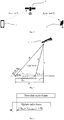
- a terminal 1 receives a global positioning system (GPS) signal of a satellite 3 and performs accurate positioning, where the common transmission time delay is twice as long as a minimum link time delay T1 and a feeder link time delay T2 between terminals 1 located closest to the satellite 3, namely 2(T1 + T2), and the feeder link time delay T2 is the feeder link time delay between the satellite 3 and a gateway station 2.
- GPS global positioning system
- the other is a relative transmission time delay, as shown in Fig. 2 , in the same beam, the time delay T3 corresponding to a propagation distance difference d3 between a user link propagation path of the terminal and the minimum link time delay path closest to the satellite 1 is the relative transmission time delay.
- NR new radio
- PRACH physical random access channel
- T PRACH Reference n is the timing reference position at which the terminal starts transmitting an uplink subframe of PRACH Preamble
- T TX PRACH n is the time at which the terminal starts transmitting PRACH Preamble
- n is a subframe number
- N TA offset is a time interval in which a base station converts from receiving the signal to transmitting the signal in a time division duplexing (TDD) duplex mode
- N TA offset 0 for a frequency division duplexing (FDD) system.
- TDD time division duplexing
- the timing advance of the uplink transmission timing position is not considered, and due to the two transmission time delays existing in the above-mentioned NTN system, if the starting transmission moment of the uplink PRACH Preamble is determined by using the above formula, the determined starting transmission moment of the uplink PRACH Preamble is delayed and can not be applied to the NTN system.
- the present application provides a method and device for determining a timing advance, configured to realize a timing advance establishing mechanism so as to meet a random access process of an NTN system.
- the embodiment of the present application provides a method for determining a timing advance by a terminal.
- the method includes: receiving and acquiring relevant parameters in a configuration message, where the relevant parameters include cell common time delay information; and determining, according to the cell common time delay information, an uplink timing advance of an uplink transmission timing position with respect to a configuration message receiving position.
- determining, according to the cell common time delay information, the uplink timing advance of the uplink transmission timing position with respect to the configuration message receiving position includes: estimating a relative transmission time delay corresponding to a propagation distance difference between a user link propagation path of the terminal and a minimum link time delay path of a reference terminal at a preset position to a satellite; determining a cell-specific timing advance of the deviation between a cell common time delay from broadcast signaling and integral multiple time slots according to the cell common time delay information; and determining the uplink timing advance according to the relative transmission time delay and the cell-specific timing advance.
- the reference terminal includes: a terrestrial reference terminal located closest to the satellite or a non-terrestrial reference terminal at a set altitude to the satellite.
- the reference terminal includes a non-terrestrial reference terminal highest from the ground.
- estimating the relative transmission time delay corresponding to the propagation distance difference between the user link propagation path of the terminal and the minimum link time delay path of the reference terminal at the preset position to the satellite includes: determining positioning information of the terminal according to a global navigation satellite system (GNSS) signal, and acquiring operation parameter information of the satellite through an ephemeris; estimating the propagation distance difference between the user link propagation path of the terminal and the minimum link time delay path of the reference terminal at the preset position to the satellite according to the positioning information and the operation parameter information of the satellite; and determining the relative transmission time delay corresponding to the propagation distance difference.
- GNSS global navigation satellite system
- determining the uplink timing advance according to the relative transmission time delay and the cell-specific timing advance includes: summing twice the relative transmission time delay with the cell-specific timing advance to obtain the uplink timing advance.
- the method further includes: receiving an RAR message by the terminal and acquiring a current uplink timing advance adjustment amount in the RAR message; and adjusting the uplink timing advance of the uplink transmission timing position with respect to the configuration message receiving position according to the current uplink timing advance adjustment amount.
- the uplink timing advance adjustment amount occupies an instruction of 16 bits.
- the method further includes: updating the current uplink timing advance by periodically or non-periodically measuring a downlink beam specific reference signal (BRS) pilot.
- BRS beam specific reference signal
- updating the current uplink timing advance by periodically or non-periodically measuring the downlink BRS pilot includes: determining a moving speed of the satellite and a moving speed of the terminal by periodically or non-periodically measuring the downlink BRS pilot; determining an adjusting step length of the current uplink timing advance according to the moving speed of the satellite, the moving speed of the terminal and a working frequency band of the satellite; and updating the current uplink timing advance according to the adjusting step length.
- determining the adjusting step length of the current uplink timing advance according to the moving speed of the satellite, the moving speed of the terminal and the working frequency band of the satellite includes: determining the length of a cyclic prefix (CP) in the received configuration message according to the working frequency band of the satellite; determining an adjusting coefficient corresponding to a speed range in which a sum value of the satellite speed and the terminal speed is located; and determining the adjusting step length of the current uplink timing advance according to the determined length of the CP and the adjusting coefficient.
- CP cyclic prefix
- T A is the uplink timing advance adjustment amount in the RAR message and N delta-TA,UE is the adjustment step length.
- 1/M is the adjusting coefficient
- M is a positive integer greater than or equal to 1
- N CP is the determined length of the CP.
- the embodiment of the present application provides a method for determining a timing advance by a network side device.
- the method includes: determining cell common time delay information; and transmitting a configuration message carrying relevant parameters to a terminal, where the relevant parameters include the cell common time delay information, and the cell common time delay information is configured for the terminal to determine an uplink timing advance of an uplink transmission timing position with respect to a configuration message receiving position.
- the method further includes: after detecting a PRACH Preamble sent by the terminal, determining an uplink timing advance adjustment amount and transmitting the uplink timing advance adjustment amount to the terminal through an RAR message.
- the uplink timing advance adjustment amount occupies an instruction of 16 bits.
- determining the uplink timing advance adjustment amount includes: selecting a time synchronization time slot number corresponding to the terminal according to a detection position at which the PRACH Preamble sent by the terminal is detected and the cell common time delay information; and determining a current uplink timing advance adjustment amount according to the time synchronization time slot number.
- the embodiment of the present application provides a terminal, including: a processor, a memory and a transceiver.
- the transceiver is configured to receive and send data under the control of the processor;
- the memory is configured to store computer instructions;
- the processor is configured to read the computer instructions in the memory and perform any method in the above first aspect.
- the embodiment of the present application provides a network side device, including: a processor, a memory and a transceiver.
- the transceiver is configured to receive and send data under the control of the processor;
- the memory is configured to store computer instructions;
- the processor is configured to read the computer instructions in the memory and perform any method in the above second aspect.
- the embodiment of the present application provides a computer storage medium having computer executable instructions stored thereon, and when the executable instructions are executed by a processor, any scheme in the above first aspect is implemented.
- the embodiment of the present application provides a computer storage medium having computer executable instructions stored thereon, and when the executable instructions are executed by a processor, any scheme in the above second aspect is implemented.
- the embodiments of the present application provide the method and device for determining the timing advance adjustment amount, mainly aiming at an establishment mechanism of the timing advance adjustment amount in a random access process of an NTN system.
- the terminal determines the timing position of the uplink transmission PRACH Preamble according to the cell common time delay information in the received configuration message, and determines the value of the timing advance N TA in the above formula according to the cell common time delay information, thereby determining a starting transmission moment of the uplink transmission PRACH Preamble in the random access process of the NTN system.
- a terminal is a device with a wireless communication function, may be deployed on land, including indoor or outdoor, handheld or vehicle-mounted devices, may also be deployed on the water surface (such as ships), and may also be deployed in the air (such as airplanes, balloons and satellites).
- the terminal may be a mobile phone, a pad, a computer with a wireless transceiving function, a virtual reality (VR) terminal, an augmented reality (AR) terminal, a wireless terminal in industrial control, a wireless terminal in self driving, a wireless terminal in remote medical, a wireless terminal in a smart grid, a wireless terminal in transportation security, a wireless terminal in a smart city, a wireless terminal in a smart home, etc., and may also be various forms of user equipment (UE), mobile stations (MS), and terminal devices.
- UE user equipment
- MS mobile stations
- a network side device which may be a gateway station, is a device that provides a wireless communication function for the terminal, including but not limited to: a base station, a gNB in 5G, a radio network controller (RNC), a node B (NB), a base station controller (BSC), a base transceiver station (BTS), and a home base station (e.g., home evolved node B, or home node B, HNB), a baseband unit (BBU), a transmitting and receiving point (TRP), a transmitting point (TP), a mobile switching center, etc.
- the gateway station of the present application may also be a device that provides a wireless communication function for the terminal in other communication systems that may occur in the future.
- a transmission timing position of a UE side PRACH sequence is determined
- an NR physical layer protocol TS38.211 gives the relationship between uplink and downlink frame timing and uplink transmission timing of a UE side PRACH
- a protocol 36.213 gives uplink transmission timing of a UE side physical uplink shared channel (PUSCH), a physical uplink control channel (PUCCH) and a channel sounding reference signal (SRS).
- PUSCH physical uplink shared channel
- PUCCH physical uplink control channel
- SRS channel sounding reference signal
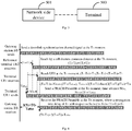
- uplink and downlink frame timing of an NR system is as shown in Fig. 3 , and an uplink radio frame transmission moment of the UE side is advanced by (N TA + N TA offset ) ⁇ Ts than a downlink radio frame starting moment of the UE.
- a method and device for determining a timing advance adjustment amount provided by the embodiments of the present application mainly aim at the establishment mechanism of the timing advance adjustment amount in the random access process of an NTN system, and illustrate the random access process of an NTN system applied by the embodiments of the present application.
- the terminal determines the timing position of the uplink transmission PRACH Preamble according to the cell common time delay information in the received configuration message, and determines the value of the timing advance N TA in the above formula according to the cell common time delay information, thereby determining the starting transmission moment of the uplink transmission PRACH Preamble in the random access process of the NTN system.
- the establishment mechanism of the timing advance adjustment amount in the random access process of the NTN system is mainly realized by a user side terminal, and in the random access process, the terminal adjusts the uplink transmission moment, which is different from the establishment of a timing advance adjustment amount of an existing NR system in which a downlink receiving timing position is directly adopted as the uplink transmission timing position in the random access process of the new radio NR system.
- the establishment mechanism is applied to the NTN system, and the uplink timing advance of the uplink transmission timing position with respect to the configuration message receiving position is determined according to the cell common time delay information, so that the uplink transmission timing position is determined according to the uplink timing advance.
- the terminal Before performing the random access process, the terminal determines the uplink transmission timing position according to the cell common time delay information in the received configuration message so as to adjust the uplink transmission moment, that is, the PRACH Preamble sequence is sent in advance or in delay, and the moment of transmission in advance or in delay is the determined uplink transmission timing position, the uplink transmission timing position is determined according to the cell common time delay information, so that a mechanism for determining a timing advance applied to the NTN system is established, to thereby guarantee the reliability of the synchronous establishing process of the NTN system and the timing accuracy of subsequent data transmission.
- a system for determining a timing advance includes a terminal 500 and a network side device 501.
- a terminal 500 is configured to receive and acquire relevant parameters in a configuration message, where the relevant parameters include cell common time delay information, and determine an uplink timing advance of an uplink transmission timing position with respect to a configuration message receiving position according to the cell common time delay information.
- a network side device 501 is configured to determine the cell common time delay information, and send the configuration message carrying the relevant parameters to the terminal, where the relevant parameters include the cell common time delay information.
- the establishment process of the timing advance is as follows.
- SIB system information block
- the relevant parameters include parameters of the cell common time delay information, a set of synchronization signal block (SSB) indexes, PRACH time-frequency resources, PRACH Preamble formats and a PRACH Preamble sequence set.
- SSB synchronization signal block
- the cell common time delay information in the embodiment of the present application is a random access synchronization time delay existing when the NTN system covers a specific downlink beam area of a cell, and the cell common time delay information is a common transmission time delay of a beam area where a terminal is located, which is obtained by the network side device according to a system broadcast message.
- the terminal may be located either on the ground or in the high air.
- the method for determining the cell common time delay information includes: the network side device acquires the cell common time delay from broadcast signaling according to a minimum link time delay T1 generated by communication between a satellite and the terminal at the closest geographical position to the satellite and a feeder link time delay T2 generated between the satellite and the network side device in the same beam of the satellite, where the cell common time delay is 2(T1+T2).
- the minimum link time delay T1 corresponds to a user link T1 in Fig. 1
- the feeder link time delay T2 corresponds to a feeder link T2 in Fig. 1 .
- the network side device in Fig. 1 is a gateway station, but the network side device in Fig. 1 is only one specific embodiment, and the network side device in the embodiments of the present application includes a gateway station, a base station, but is not limited to a gateway station and a base station.
- the terminal receives and acquires the cell common time delay information in the configuration message, and determines the uplink timing advance of the uplink transmission timing position with respect to the configuration message receiving position according to the cell common time delay information.
- the terminal receives the configuration message sent by the network side device through the SIB1, and the relevant parameters in the acquired configuration message include: the parameters of the cell common time delay information, the set of synchronization signal block (SSB) indexes, the PRACH time-frequency resources, the PRACH Preamble formats and the PRACH Preamble sequence set.
- the relevant parameters in the acquired configuration message include: the parameters of the cell common time delay information, the set of synchronization signal block (SSB) indexes, the PRACH time-frequency resources, the PRACH Preamble formats and the PRACH Preamble sequence set.
- SSB synchronization signal block
- the uplink transmission timing position is determined based on two types of random access synchronization time delays when the NTN system covers the specific downlink beam area of the cell.
- One type of random access synchronization time delay is a common transmission time delay
- the terminal determines the common transmission time delay existing when the NTN system covers the specific downlink beam area of the cell by receiving the cell common time delay information, and as shown in Fig.
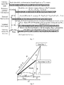
- the common transmission time delay is (T1+T2); another type of random access synchronization time delay is a relative transmission time delay, and a time delay corresponding to a propagation distance difference between a user link propagation path of the terminal and a minimum link time delay path of a reference terminal at the preset geographic position to the satellite in the same coverage cell is the relative transmission time delay, where when the reference terminal is a terrestrial reference terminal closest to the satellite, the propagation distance difference corresponds to d3 in Fig. 2 , and when the reference terminal is a non-terrestrial reference terminal at a set altitude to the satellite, the propagation distance difference corresponds to d3 in Fig. 8 .
- the method for determining the uplink timing advance of the uplink transmission timing position with respect to the configuration message receiving position according to the cell common time delay information includes the following operations.
- the terminal for estimating includes a terrestrial terminal or a non- terrestrial terminal
- the reference terminal includes: a terrestrial reference terminal located closest to the satellite or a non-terrestrial reference terminal at a set altitude to the satellite, where the non-terrestrial reference terminal at the set altitude to the satellite includes a non-terrestrial reference terminal located highest from the ground, and may be, for example, a reference terminal located at 30000 km from the ground.
- the relative transmission time delay is determined by taking the uplink transmission position of the terminal at a preset position to the satellite as a reference position, when the reference position is an uplink transmission position of the terrestrial reference terminal located closest to the satellite, the obtained relative transmission time delay is d3 in Fig. 2 , and when the reference position is an uplink transmission position of the non-terrestrial reference terminal highest from the ground, the obtained relative transmission time delay is d3 in Fig. 8 .
- a cell-specific timing advance of the deviation between the cell common time delay from broadcast signaling and integral multiple time slots is determined according to the cell common time delay information.
- the uplink timing advance is determined according to the relative transmission time delay and the cell-specific timing advance.
- the terminal determines the uplink transmission timing position according to the following two parts of information: one part is the cell common time delay information in the relevant parameters sent by the network side device, and the other part is the relative transmission time delay estimated by the terminal according to positioning information of the terminal and operation parameters of the satellite, where the terminal is the terrestrial terminal or the non-terrestrial terminal, such as a high-altitude terminal.
- the terminal determines the timing advance of the uplink transmission timing position with respect to the configuration message receiving position according to the cell common time delay information and the relative transmission time delay. According to the position of the terminal and the position of the reference terminal, the estimated relative transmission time delay is divided into the following four cases.
- the reliability of the NTN system in the synchronous establishment process of the random access process and the timing accuracy of the subsequent data transmission are ensured with respect to a timing advance establishment mechanism adopting the NR system.
- the terminal determines the timing advance of the uplink transmission timing position with respect to the configuration message receiving position according to the cell common time delay information; and on the other hand, the terminal estimates a relative transmission time delay corresponding to the propagation distance difference between the user link propagation path and a minimum link delay path closest to the satellite according to the positioning information of the terminal. The terminal determines the timing advance according to the relative transmission time delay and the cell-specific timing advance.
- the timing advance is determined according to the following manners.
- the terminal determines the positioning information of the terminal according to a global navigation satellite system (GNSS) signal, and acquires operation parameter information of the satellite through an ephemeris; estimates the propagation distance difference between the user link propagation path of the terminal and the minimum link delay path closest to the satellite according to the positioning information and the operation parameter information of the satellite; and determines the relative transmission time delay corresponding to the estimated propagation distance difference.
- GNSS global navigation satellite system
- the timing advance is determined according to the relative transmission time delay and the cell-specific timing advance.
- N TA 2 T 3 + T offset ; where N TA is the timing advance, and T3 is the relative transmission time delay.
- a downlink of the terminal takes a received downlink index, including indexes of frames, subframes and time slots, as a current subframe index; when the terminal firstly obtains uplink signal frame synchronization in a random access process, the uplink signal frame synchronization is consistent with the cell common time delay after the relative transmission time delay is supplemented, that is, the uplink transmission timing position with the shortest common distance between the cell and the satellite serves as a reference, the time for all terminals in the cell to reach the network side device serves as the reference with the common distance of the cell, and at the moment, the uplink subframe indexes of all the terminals in one cell are consistent.
- an NTN-based system in the present embodiments includes: a gateway station BS, a terminal UE1 and a reference terminal UE2, where the reference terminal UE2 is located on the ground and is the terminal with the shortest distance from the gateway station BS in the cell, the uplink transmission timing position of the reference terminal UE2 is taken as the reference, and the UE1 is located on the ground and is any UE in the cell.
- the timing relationship between the UE side and the BS side is as follows.
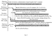
- the gateway station sends a downlink synchronization channel/signal at the T A moment and sends relevant parameters in a configuration message to the terminal.
- the downlink synchronization channel/signal may be an SIB1 message.
- the reference terminal UE2 is delayed by T 1 +T 2 with respect to the T A moment of transmission by the gateway station, where T 1 is a minimum link time delay closest to the satellite, and T 2 is a feeder link time delay.
- (T C -T A ) (T 1 +T 2 )+T 3 , i.e. the terminal UE1 is delayed by T 1 +T 2 +T 3 with respect to the T A moment of transmitting by the gateway station.
- N TA 2 T 3 + T offset , where 2 T 3 + T offset is greater than zero , i .e . , N TA > 0 .
- the base station After a base station has detected a PRACH Preamble sequence sent by the terminal, the base station sends a random access response (RAR) message to the terminal.
- RAR random access response
- the uplink transmission timing position of the reference terminal UE2 is taken as a reference and a terminal UE3 is located at any UE in the high air
- the timing relationship between the UE side and the BS side is as follows.
- N TA 2 T 3 + T offset , where 2 T 3 + T offset is less than zero , i . e . , N TA ⁇ 0 .
- a reference terminal UE0 located at a certain height in the air serves as a reference moment of an uplink transmission timing position
- all the terminals include a terrestrial terminal and a non-terrestrial terminal (a high-altitude terminal)
- the basis reference of the uplink transmission starting moment is the uplink transmission timing position of the terminal UE0, and at the moment, uplink subframe indexes of all the terminals may be kept consistent.
- the timing relationship between the UE side and the BS side is as follows.
- the uplink timing advance adjustment amount is determined and sent to the terminal through the RAR message.
- the method for determining the uplink timing advance adjustment amount by the network side device includes: a time synchronization time slot number corresponding to the terminal is selected according to the detection position at which the PRACH Preamble sent by the terminal is detected and the cell common time delay information; and a current uplink timing advance adjustment amount T A is determined according to the selected time synchronization time slot number corresponding to the terminal.
- the uplink timing advance adjustment amount occupies an instruction of 16 bits, i.e., T A may be taken to be 0, 1, 2 ..., 65535.
- the terminal receives the RAR message and acquires the uplink timing advance adjustment amount in the RAR message; and adjusts the uplink timing advance of the uplink transmission timing position with respect to the configuration message receiving position according to the uplink timing advance adjustment amount.
- the terminal acquires uplink synchronization according to the uplink timing advance adjustment amount, and adjusts the uplink transmission timing position according to the current uplink timing advance adjustment amount according to the following formula.
- the terminal updates the current uplink timing advance
- updating mechanisms may be as follows: one updating mechanism is that the terminal updates the current uplink timing advance by periodically or non-periodically measuring a downlink BRS pilot; and the other updating mechanism is that the terminal updates the current uplink timing advance according to the uplink timing advance adjustment amount carried in the received RAR message.
- the two updating mechanisms is used alternately or separately.
- the mode for updating the uplink timing advance in the existing NR system is as follows.
- N TA,old and N TA, new used in the process of updating the uplink timing advance are defined.
- N TA,old a current N TA value when the UE does not receive a new uplink timing advance adjustment amount T A .
- N TA, new a value when the UE receives the new uplink timing advance adjustment amount T A and after the current N TA is updated according to the T A .
- the UE After receiving the random access response, the UE analyzes the uplink timing advance adjustment amount T A from the random access response, calculates the uplink timing advance N TA , adjusts the uplink transmission timing through the N TA value, and reserves the N TA as an initial value for adjustment in a subsequent uplink synchronization process.
- N TA T A ⁇ 16
- the granularity is 16 Ts
- an uplink timing synchronization command word T A is of 12 bits
- the T A is taken as 0, 1, 2, ..., 4095.
- the uplink timing synchronization command word T A of 12 bits can support the maximum cell radius of 320 km, and meets the design requirement for supporting the cell radius of 150 km to 300 km provided in TR38.913 by the 3GPP.
- the gateway station will periodically send the uplink timing synchronization command word T A to the UE.
- the UE updates the value of N TA,old into N TA, new , and then adjusts the uplink transmission timing of the UE by using the N TA, new .
- N TA,old N TA ,old + T A ⁇ 31 ⁇ 16 ;
- N TA, new > N TA,old indicating that the transmission signal timing is in advance on the basis of the current timing.
- N TA, new N TA,old , indicating that the transmission signal timing keeps unchanged on the basis of the current timing.
- the terminal since the satellite moves at a speed of about 8 km/s per second at an orbital height of 1175 km from the surface, considering that the maximum distance between the satellite and the terminal is about 3090 km, the maximum distance between the satellite and the network side device such as the gateway station is 3531 km, and the maximum time delay between the terminal and the gateway station is 22 ms, the path length variation caused by satellite movement is about 300-400 meters, the corresponding path time delay is about 1.32 us, and the length of a cyclic prefix (CP) in the PRACH Preamble sequence exceeding a subcarrier by 120 kHz IS 0.59 us, so the terminal needs to regularly measure the downlink BRS pilot in the transmission process, know the transmission path CHANGE caused by movement through measurement, pre-compensate the transmission advance in advance, and reduce the performance loss of inaccurate synchronization accuracy caused by the movement performance.
- the terminal determines a moving speed of the satellite and a moving speed of the terminal by periodically or non-periodically measuring a downlink beam specific reference signal (BRS) pilot; determines an adjusting step length of the current uplink timing advance according to the moving speed of the satellite, the moving speed of the terminal and a working frequency band of the satellite; and updates the current uplink timing advance according to the adjusting step length.
- BRS downlink beam specific reference signal
- Determining the adjusting step length of the current uplink timing advance according to the moving speed of the satellite, the moving speed of the terminal and the working frequency band of the satellite includes that: the length of the CP in the received configuration message is determined according to the working frequency band of the satellite; an adjusting coefficient corresponding to a speed range in which a sum value of a satellite speed and a terminal speed is located is determined; and the adjusting step length of the current uplink timing advance is determined according to the determined length of the CP and the adjusting coefficient.
- the uplink timing advance adjustment amount T A contains 11 bits.
- N TA, new N TA,old , indicating that the transmission signal timing keeps unchanged on the basis of the current timing.
- the sum of the satellite speed and the terminal speed may be divided into three levels, high, medium and low, respectively corresponding to different M values, as shown in Table 1.
- Table 1 Sum of Satellite Speed and Terminal Speed M High 1 Medium 2 Low 3
- the establishment of the timing advance adjustment amount between the terminal and the network side device in a random access system is completed through the method according to the embodiments of the present application.
- the downlink of the terminal takes the received downlink frame index, subframe index and time slot index as current subframe indexes; when the terminal firstly obtains the uplink signal frame synchronization in the random access process, the uplink signal frame synchronization is consistent with the cell common time delay after the relative transmission time delay is supplemented, that is, the uplink transmission timing position with the shortest common distance between the cell and the satellite serves as a reference, and the time for all terminals in the cell to reach the network side device serves as the reference with the common distance of the cell.
- the method provided by the embodiments of the present application can ensure that the uplink subframe indexes of all the terminals in the satellite beam coverage cell keep consistent.
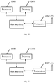
- a first terminal for determining a timing advance includes: a processor 1000, a memory 1001 and a transceiver 1002.
- the processor 1000 is responsible for managing a bus architecture and general processing, and the memory 1001 is configured to store data used by the processor 1000 in performing operations.
- the transceiver 1002 is configured to receive and transmit data under the control of the processor 1000.
- the bus architecture may include any number of interconnected buses and bridges, specifically, one or more processors represented by the processor 1000 and various circuits of the memory represented by the memory 1001 are linked together.
- the bus architecture may also link various other circuits such as peripheral devices, voltage regulators, power management circuits, and the like, which are well known in the art, and therefore, it will not be described further herein.
- a bus interface provides an interface.
- the processor 1000 is responsible for managing the bus architecture and general processing, and the memory 1001 may store data used by the processor 1000 in performing operations.
- the processes disclosed according to the embodiments of the present application may be implemented in or by the processor 1000.
- the steps of a signal processing flow may be performed by an integrated logic circuit in hardware or instructions in software in the processor 1000.
- the processor 1000 may be a general processor, a digital signal processor, a specific integrated circuit, a field programmable gate array or other programmable logic device, a discrete gate or transistor logic device, and a discrete hardware component, which may implement or perform the methods, steps, and logic block diagrams disclosed in the embodiments herein.
- the general processor may be a microprocessor, any conventional processor, etc.
- the steps of the method disclosed in connection with the embodiments of the present application may be embodied directly in hardware processor execution or in a combination of hardware and software modules in the processor.
- the software module may be located in a random access memory, flash memory, read only memory, programmable read only memory, or electrically erasable programmable memory, a register, or other storage media as is well known in the art.
- the storage medium is located in the memory 1001, and the processor 1000 reads the information in the memory 1001 and completes the steps of the signal processing flow in combination with the hardware thereof.
- the processor 1000 is configured to read a program in the memory 1001 and execute the following processes: receiving and acquiring relevant parameters in a configuration message, where the relevant parameters include cell common time delay information; and determining, according to the cell common time delay information, an uplink timing advance of an uplink transmission timing position with respect to a configuration message receiving position.
- the processor is specifically configured to: estimate a relative transmission time delay corresponding to a propagation distance difference between a user link propagation path of the terminal and a minimum link time delay path closest to a satellite; determine a cell-specific timing advance of the deviation between a cell common time delay from broadcast signaling and integral multiple time slots according to the cell common time delay information; and determine the uplink timing advance according to the relative transmission time delay and the cell-specific timing advance.
- the processor is specifically configured to: determine positioning information of the terminal according to a global navigation satellite system (GNSS) signal, and acquire operation parameter information of the satellite through an ephemeris; estimate the propagation distance difference between the user link propagation path of the terminal and the minimum link time delay path closest to the satellite according to the positioning information and the operation parameter information of the satellite; and determine the relative transmission time delay corresponding to the estimated propagation distance difference.
- GNSS global navigation satellite system
- the processor is specifically configured to: sum twice the relative transmission time delay with the cell-specific timing advance to obtain the uplink timing advance.
- the processor is further specifically configured to: receive an RAR message by the terminal and acquire a current uplink timing advance adjustment amount in the RAR message; and adjust the uplink timing advance of the uplink transmission timing position with respect to the configuration message receiving position according to the current uplink timing advance adjustment amount.
- the uplink timing advance adjustment amount occupies an instruction of 16 bits.
- the processor is further specifically configured to: update the current uplink timing advance by periodically or non-periodically measuring a downlink BRS pilot.
- the processor is specifically configured to: determine a moving speed of the satellite and a moving speed of the terminal by periodically or non-periodically measuring the downlink BRS pilot; determine an adjusting step length of the current uplink timing advance according to the moving speed of the satellite, the moving speed of the terminal and a working frequency band of the satellite; and update the current uplink timing advance according to the adjusting step length.
- the processor is specifically configured to: determine the length of a CP in the received configuration message according to the working frequency band of the satellite; determine an adjusting coefficient corresponding to a speed range in which a sum value of the satellite speed and the terminal speed is located; and determine the adjusting step length of the current uplink timing advance according to the determined length of the CP and the adjusting coefficient.
- a first network side device for determining a timing advance includes: a processor 1100, a memory 1101 and a transceiver 1102.
- the processor 1100 is responsible for managing a bus architecture and general processing, and the memory 1101 may store data used by the processor 1100 in performing operations.
- the transceiver 1102 is configured to receive and transmit data under the control of the processor 1100.
- the bus architecture may include any number of interconnected buses and bridges, specifically, one or more processors represented by the processor 1100 and various circuits of the memory represented by the memory 1101 are linked together.
- the bus architecture may also link various other circuits such as peripheral devices, voltage regulators, power management circuits, and the like, which are well known in the art, and therefore, it will not be described further herein.
- a bus interface provides an interface.
- the processor 1100 is responsible for managing the bus architecture and general processing, and the memory 1101 may store data used by the processor 1100 in performing operations.
- the processes disclosed according to the embodiments of the present application may be implemented in or by the processor 1100.
- the steps of a signal processing flow may be performed by an integrated logic circuit in hardware or instructions in software in the processor 1100.
- the processor 1100 may be a general processor, a digital signal processor, a specific integrated circuit, a field programmable gate array or other programmable logic device, a discrete gate or transistor logic device, and a discrete hardware component, which may implement or perform the methods, steps, and logic block diagrams disclosed in the embodiments herein.
- the general processor may be a microprocessor, any conventional processor, etc.
- the steps of the method disclosed in connection with the embodiments of the present application may be embodied directly in hardware processor execution or in a combination of hardware and software modules in the processor.
- the software module may be located in a random access memory, flash memory, read only memory, programmable read only memory, or electrically erasable programmable memory, a register, or other storage media as is well known in the art.
- the storage medium is located in the memory 1101, and the processor 1100 reads the information in the memory 1101 and completes the steps of the signal processing flow in combination with the hardware thereof.
- the processor 1100 is configured to read a program in the memory 1101 and execute the following processes: determining cell common time delay information; and transmitting a configuration message carrying relevant parameters to a terminal, where the relevant parameters include the cell common time delay information.
- the processor is specifically configured to: after detecting a PRACH Preamble sent by the terminal, determine an uplink timing advance adjustment amount and send the uplink timing advance adjustment amount to the terminal through an RAR message.
- the uplink timing advance adjustment amount occupies an instruction of 16 bits.
- the processor is specifically configured to: select a time synchronization time slot number corresponding to the terminal according to a detection position at which the PRACH Preamble sent by the terminal is detected and the cell common time delay information; and determine a current uplink timing advance adjustment amount according to the time synchronization time slot number.
- a second terminal for determining a timing advance includes: a receiving module 1200, and a determining module 1201.
- the receiving module 1200 is configured to receive and acquire relevant parameters in a configuration message, where the relevant parameters include cell common time delay information.
- the determining module 1201 is configured to determine, according to the cell common time delay information, an uplink timing advance of an uplink transmission timing position with respect to a configuration message receiving position.
- the determining module 1201 is specifically configured to: estimate a relative transmission time delay corresponding to a propagation distance difference between a user link propagation path of the terminal and a minimum link time delay path closest to a satellite; determine a cell-specific timing advance of the deviation between a cell common time delay from broadcast signaling and integral multiple time slots according to the cell common time delay information; and determine the uplink timing advance according to the relative transmission time delay and the cell-specific timing advance.
- the determining module 1201 is specifically configured to: determine positioning information of the terminal according to a global navigation satellite system (GNSS) signal, and acquire operation parameter information of the satellite through an ephemeris; estimate the propagation distance difference between the user link propagation path of the terminal and the minimum link time delay path closest to the satellite according to the positioning information and the operation parameter information of the satellite; and determine the relative transmission time delay corresponding to the estimated propagation distance difference.
- GNSS global navigation satellite system
- the determining module 1201 is specifically configured to: sum twice the relative transmission time delay with the cell-specific timing advance to obtain the uplink timing advance.
- the terminal further includes the receiving module 1200, specifically configured to: receive an RAR message by the terminal and acquire a current uplink timing advance adjustment amount in the RAR message; and adjust the uplink timing advance of the uplink transmission timing position with respect to the configuration message receiving position according to the current uplink timing advance adjustment amount.
- the receiving module 1200 specifically configured to: receive an RAR message by the terminal and acquire a current uplink timing advance adjustment amount in the RAR message; and adjust the uplink timing advance of the uplink transmission timing position with respect to the configuration message receiving position according to the current uplink timing advance adjustment amount.
- the uplink timing advance adjustment amount occupies an instruction of 16 bits.
- the terminal further includes an updating module 1202, configured to: update the current uplink timing advance by periodically or non-periodically measuring a downlink BRS pilot.
- the updating module 1202 is specifically configured to: determine a moving speed of the satellite and a moving speed of the terminal by periodically or non-periodically measuring the downlink BRS pilot; determine an adjusting step length of the current uplink timing advance according to the moving speed of the satellite, the moving speed of the terminal and a working frequency band of the satellite; and update the current uplink timing advance according to the adjusting step length.
- the updating module 1202 is specifically configured to: determine the length of a CP in the received configuration message according to the working frequency band of the satellite; determine an adjusting coefficient corresponding to a speed range in which a sum value of the satellite speed and the terminal speed is located; and determine the adjusting step length of the current uplink timing advance according to the determined length of the CP and the adjusting coefficient.
- a second network side device for determining a timing advance includes a determining module 1301 and a transmission module 1302, where the determining module 1301 is configured to determine cell common time delay information; and the transmission module 1302 is configured to send a configuration message carrying relevant parameters to a terminal, where the relevant parameters include the cell common time delay information.
- the network side device further includes the transmission module, configured to: after detecting a PRACH Preamble sent by the terminal, determine an uplink timing advance adjustment amount and send the uplink timing advance adjustment amount to the terminal through an RAR message.
- the uplink timing advance adjustment amount occupies an instruction of 16 bits.
- the transmission module is specifically configured to: select a time synchronization time slot number corresponding to the terminal according to a detection position at which the PRACH Preamble sent by the terminal is detected and the cell common time delay information; and determine a current uplink timing advance adjustment amount according to the time synchronization time slot number.
- the embodiment of the present application provides a readable storage medium that is a non-volatile storage medium, the readable storage medium is a non-volatile readable storage medium including a program code, and when the program code runs on a computing device, the program code is configured to enable the computing device to perform the action of the above network side device to determine the timing advance.
- the embodiment of the present application provides a readable storage medium that is a non-volatile storage medium, the readable storage medium is a non-volatile readable storage medium including a program code, and when the program code runs on a computing device, the program code is configured to enable the computing device to perform the action of the above terminal to determine the timing advance.
- the embodiment of the present application provides a computer program product including instructions, and when the instructions are executed on a computer, a computing device performs the action of the above terminal to determine the timing advance.
- the embodiment of the present application provides a computer program product including instructions, and when the instructions are executed on a computer, a computing device performs the action of the above network side device to determine the timing advance.
- the embodiment of the present application also provides a method for determining a timing advance by a terminal.
- the terminal corresponding to the method is the terminal in the embodiments of the present application, and the principle for solving the problem by the method is similar to that of the device, the implementation of the method may be referred to as the implementation of the system, and the repetition is omitted.
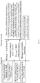
- the method for determining the timing advance by the terminal includes steps 1400 and 1401.
- Step 1400 relevant parameters in a configuration message are received and acquired, where the relevant parameters include cell common time delay information.
- Step 1401 according to the cell common time delay information, an uplink timing advance of an uplink transmission timing position with respect to a configuration message receiving position is determined.
- determining, according to the cell common time delay information, the uplink timing advance of the uplink transmission timing position with respect to the configuration message receiving position includes: estimating a relative transmission time delay corresponding to a propagation distance difference between a user link propagation path of the terminal and a minimum link time delay path closest to a satellite; determining a cell-specific timing advance of the deviation between a cell common time delay from broadcast signaling and integral multiple time slots according to the cell common time delay information; and determining the uplink timing advance according to the relative transmission time delay and the cell-specific timing advance.
- estimating the relative transmission time delay includes: determining positioning information of the terminal according to a global navigation satellite system (GNSS) signal, and acquiring operation parameter information of the satellite through an ephemeris; estimating the propagation distance difference between the user link propagation path of the terminal and the minimum link time delay path closest to the satellite according to the positioning information and the operation parameter information of the satellite; and determining the relative transmission time delay corresponding to the estimated propagation distance difference.
- GNSS global navigation satellite system
- determining the uplink timing advance according to the relative transmission time delay and the cell-specific timing advance includes: summing twice the relative transmission time delay with the cell-specific timing advance to obtain the uplink timing advance.
- the method further includes: receiving an RAR message by the terminal and acquiring a current uplink timing advance adjustment amount in the RAR message; and adjusting the uplink timing advance of the uplink transmission timing position with respect to the configuration message receiving position according to the current uplink timing advance adjustment amount.
- the uplink timing advance adjustment amount occupies an instruction of 16 bits.
- the method further includes: updating the current uplink timing advance by periodically or non-periodically measuring a downlink BRS pilot.
- updating the current uplink timing advance by periodically or non-periodically measuring the downlink BRS pilot includes: determining a moving speed of the satellite and a moving speed of the terminal by periodically or non-periodically measuring the downlink BRS pilot; determining an adjusting step length of the current uplink timing advance according to the moving speed of the satellite, the moving speed of the terminal and a working frequency band of the satellite; and updating the current uplink timing advance according to the adjusting step length.
- determining the adjusting step length of the current uplink timing advance according to the moving speed of the satellite, the moving speed of the terminal and the working frequency band of the satellite includes: determining the length of a CP in the received configuration message according to the working frequency band of the satellite; determining an adjusting coefficient corresponding to a speed range in which a sum value of the satellite speed and the terminal speed is located; and determining the adjusting step length of the current uplink timing advance according to the determined length of the CP and the adjusting coefficient.
- the embodiment of the present application also provides a method for determining a timing advance by a network side device.
- the network side device corresponding to the method is the network side device in the embodiments of the present application, and the principle for solving the problem by the method is similar to that of the device, the implementation of the method may be referred to as the implementation of the system, and the repetition is omitted.
- a method for determining a timing advance by a network side device includes: step 1500 and step 1501.
- Step 1500 cell common time delay information is determined.
- Step 1501 a configuration message carrying relevant parameters is sent to a terminal, where the relevant parameters include the cell common time delay information.
- the method further includes: after detecting a PRACH Preamble sent by the terminal, determining an uplink timing advance adjustment amount and transmitting the uplink timing advance adjustment amount to the terminal through an RAR message.
- the uplink timing advance adjustment amount occupies an instruction of 16 bits.
- determining the uplink timing advance adjustment amount includes: selecting a time synchronization time slot number corresponding to the terminal according to a detection position at which the PRACH Preamble sent by the terminal is detected and the cell common time delay information; and determining a current uplink timing advance adjustment amount according to the time synchronization time slot number.
- the present application may also be implemented in hardware and/or software (including firmware, resident software, microcode, etc.). Further, the application may take the form of a computer program product usable on a computer or computer-readable storage medium having a computer-usable or computer-readable program code embodied in the medium for use by or in connection with an instruction execution system.
- the computer-usable or computer-readable medium can be any medium that may contain, store, communicate, transmit, or transport the program for use by or in connection with the instruction execution system, device, or equipment.
Landscapes
- Engineering & Computer Science (AREA)
- Computer Networks & Wireless Communication (AREA)
- Signal Processing (AREA)
- Physics & Mathematics (AREA)
- General Physics & Mathematics (AREA)
- Astronomy & Astrophysics (AREA)
- Aviation & Aerospace Engineering (AREA)
- Quality & Reliability (AREA)
- Radar, Positioning & Navigation (AREA)
- Remote Sensing (AREA)
- Electromagnetism (AREA)
- Mathematical Physics (AREA)
- Mobile Radio Communication Systems (AREA)
Abstract
Description
- The present application claims priorities to the
Chinese Patent Application No. 201910115060.0, filed to the Chinese Patent Office on February 14, 2019 Chinese Patent Application No. 201910185664.2, filed to the Chinese Patent Office on March 12, 2019 - The present application relates to the field of non-terrestrial networks (NTNs), in particular to a method and device for determining a timing advance.
- An NTN includes a satellite communication system, has a cell radius far larger than that of a conventional cellular communication system, introduces ultra-large propagation time delay, and has two following types of random access synchronization time delay aiming at a specific downlink beam covering a cell by the satellite communication system.
- One is a common transmission time delay, as shown in
Fig. 1 , aterminal 1 receives a global positioning system (GPS) signal of asatellite 3 and performs accurate positioning, where the common transmission time delay is twice as long as a minimum link time delay T1 and a feeder link time delay T2 betweenterminals 1 located closest to thesatellite 3, namely 2(T1 + T2), and the feeder link time delay T2 is the feeder link time delay between thesatellite 3 and agateway station 2. - The other is a relative transmission time delay, as shown in
Fig. 2 , in the same beam, the time delay T3 corresponding to a propagation distance difference d3 between a user link propagation path of the terminal and the minimum link time delay path closest to thesatellite 1 is the relative transmission time delay. - In a new radio (NR) system, for all physical random access channel (PRACH) Preambles, a current downlink timing position is taken as a reference timing position, and there is no timing advance at an uplink transmission timing position, the formula is as follows:


- At present, in a process of establishing a timing advance, the timing advance of the uplink transmission timing position is not considered, and due to the two transmission time delays existing in the above-mentioned NTN system, if the starting transmission moment of the uplink PRACH Preamble is determined by using the above formula, the determined starting transmission moment of the uplink PRACH Preamble is delayed and can not be applied to the NTN system. In summary, at present, there is no timing advance establishment mechanism and maintenance mechanism suitable for the NTN system.
- The present application provides a method and device for determining a timing advance, configured to realize a timing advance establishing mechanism so as to meet a random access process of an NTN system.
- In a first aspect, the embodiment of the present application provides a method for determining a timing advance by a terminal. The method includes: receiving and acquiring relevant parameters in a configuration message, where the relevant parameters include cell common time delay information; and determining, according to the cell common time delay information, an uplink timing advance of an uplink transmission timing position with respect to a configuration message receiving position.
- As an optional implementation, determining, according to the cell common time delay information, the uplink timing advance of the uplink transmission timing position with respect to the configuration message receiving position, includes: estimating a relative transmission time delay corresponding to a propagation distance difference between a user link propagation path of the terminal and a minimum link time delay path of a reference terminal at a preset position to a satellite; determining a cell-specific timing advance of the deviation between a cell common time delay from broadcast signaling and integral multiple time slots according to the cell common time delay information; and determining the uplink timing advance according to the relative transmission time delay and the cell-specific timing advance.
- As an optional implementation, the reference terminal includes: a terrestrial reference terminal located closest to the satellite or a non-terrestrial reference terminal at a set altitude to the satellite.
- As an optional implementation, the reference terminal includes a non-terrestrial reference terminal highest from the ground.
- As an optional implementation, estimating the relative transmission time delay corresponding to the propagation distance difference between the user link propagation path of the terminal and the minimum link time delay path of the reference terminal at the preset position to the satellite, includes: determining positioning information of the terminal according to a global navigation satellite system (GNSS) signal, and acquiring operation parameter information of the satellite through an ephemeris; estimating the propagation distance difference between the user link propagation path of the terminal and the minimum link time delay path of the reference terminal at the preset position to the satellite according to the positioning information and the operation parameter information of the satellite; and determining the relative transmission time delay corresponding to the propagation distance difference.
- As an optional implementation, determining the uplink timing advance according to the relative transmission time delay and the cell-specific timing advance, includes: summing twice the relative transmission time delay with the cell-specific timing advance to obtain the uplink timing advance.
- As an optional implementation, the method further includes: receiving an RAR message by the terminal and acquiring a current uplink timing advance adjustment amount in the RAR message; and adjusting the uplink timing advance of the uplink transmission timing position with respect to the configuration message receiving position according to the current uplink timing advance adjustment amount.
- As an optional implementation, when a subcarrier spacing of a PUSCH is 120 KHz, the uplink timing advance adjustment amount occupies an instruction of 16 bits.
- As an optional implementation, the method further includes: updating the current uplink timing advance by periodically or non-periodically measuring a downlink beam specific reference signal (BRS) pilot.
- As an optional implementation, updating the current uplink timing advance by periodically or non-periodically measuring the downlink BRS pilot, includes: determining a moving speed of the satellite and a moving speed of the terminal by periodically or non-periodically measuring the downlink BRS pilot; determining an adjusting step length of the current uplink timing advance according to the moving speed of the satellite, the moving speed of the terminal and a working frequency band of the satellite; and updating the current uplink timing advance according to the adjusting step length.
- As an optional implementation, determining the adjusting step length of the current uplink timing advance according to the moving speed of the satellite, the moving speed of the terminal and the working frequency band of the satellite, includes: determining the length of a cyclic prefix (CP) in the received configuration message according to the working frequency band of the satellite; determining an adjusting coefficient corresponding to a speed range in which a sum value of the satellite speed and the terminal speed is located; and determining the adjusting step length of the current uplink timing advance according to the determined length of the CP and the adjusting coefficient.
- As an optional implementation, the current uplink timing advance is updated according to the adjusting step length according to the following formula:

- As an optional implementation, the adjusting step length of the current uplink timing advance is determined according to the determined length of the CP and the adjusting coefficient according to the following formula:

- 1/M is the adjusting coefficient, M is a positive integer greater than or equal to 1, and NCP is the determined length of the CP.
- In a second aspect, the embodiment of the present application provides a method for determining a timing advance by a network side device. The method includes: determining cell common time delay information; and transmitting a configuration message carrying relevant parameters to a terminal, where the relevant parameters include the cell common time delay information, and the cell common time delay information is configured for the terminal to determine an uplink timing advance of an uplink transmission timing position with respect to a configuration message receiving position.
- As an optional implementation, the method further includes: after detecting a PRACH Preamble sent by the terminal, determining an uplink timing advance adjustment amount and transmitting the uplink timing advance adjustment amount to the terminal through an RAR message.
- As an optional implementation, when a subcarrier spacing of a PUSCH is 120 KHz, the uplink timing advance adjustment amount occupies an instruction of 16 bits.
- As an optional implementation, determining the uplink timing advance adjustment amount, includes: selecting a time synchronization time slot number corresponding to the terminal according to a detection position at which the PRACH Preamble sent by the terminal is detected and the cell common time delay information; and determining a current uplink timing advance adjustment amount according to the time synchronization time slot number.
- In a third aspect, the embodiment of the present application provides a terminal, including: a processor, a memory and a transceiver. The transceiver is configured to receive and send data under the control of the processor; the memory is configured to store computer instructions; and the processor is configured to read the computer instructions in the memory and perform any method in the above first aspect.
- In a fourth aspect, the embodiment of the present application provides a network side device, including: a processor, a memory and a transceiver. The transceiver is configured to receive and send data under the control of the processor; the memory is configured to store computer instructions; and the processor is configured to read the computer instructions in the memory and perform any method in the above second aspect.
- In a fifth aspect, the embodiment of the present application provides a computer storage medium having computer executable instructions stored thereon, and when the executable instructions are executed by a processor, any scheme in the above first aspect is implemented.
- In a sixth aspect, the embodiment of the present application provides a computer storage medium having computer executable instructions stored thereon, and when the executable instructions are executed by a processor, any scheme in the above second aspect is implemented.
- The embodiments of the present application provide the method and device for determining the timing advance adjustment amount, mainly aiming at an establishment mechanism of the timing advance adjustment amount in a random access process of an NTN system. In the random access process, the terminal determines the timing position of the uplink transmission PRACH Preamble according to the cell common time delay information in the received configuration message, and determines the value of the timing advance NTA in the above formula according to the cell common time delay information, thereby determining a starting transmission moment of the uplink transmission PRACH Preamble in the random access process of the NTN system.
- In order to more clearly illustrate the technical solutions in the embodiments of the present application, the drawings used in the description of the embodiments are briefly described below, and it is obvious that the drawings in the description below are only some embodiments of the present application, and that other drawings can be obtained from these drawings without involving any inventive effort for those ordinarily skilled in the art.
-
Fig. 1 is a schematic diagram of a common transmission time delay of an NTN system according to an embodiment of the present application. -
Fig. 2 is a schematic diagram of a relative transmission time delay of an NTN system according to an embodiment of the present application. -
Fig. 3 is a schematic diagram of an uplink and downlink frame timing relationship of an NR system according to an embodiment of the present application. -
Fig. 4 is a schematic diagram of a random access process of an NTN system according to an embodiment of the present application. -
Fig. 5 is a schematic diagram of a system for determining a timing advance according to an embodiment of the present application. -
Fig. 6 is a schematic diagram of a process for establishing a timing advance according to an embodiment of the present application. -
Fig. 7 is a schematic diagram of another process for establishing a timing advance according to an embodiment of the present application. -
Fig. 8 is a schematic diagram of a reference terminal position for a timing advance according to an embodiment of the present application. -
Fig. 9 is a schematic diagram of a last process for establishing a timing advance according to an embodiment of the present application. -
Fig. 10 is a schematic diagram of a first terminal for determining a timing advance according to an embodiment of the present application. -
Fig. 11 is a schematic diagram of a first network side device for determining a timing advance according to an embodiment of the present application. -
Fig. 12 is a block diagram of a second terminal for determining a timing advance according to an embodiment of the present application. -
Fig. 13 is a block diagram of a second network side device for determining a timing advance according to an embodiment of the present application. -
Fig. 14 is a flowchart of a method for determining a timing advance by a terminal according to an embodiment of the present application. -
Fig. 15 is a flowchart of a method for determining a timing advance by a network side device according to an embodiment of the present application. - In the following, some terms in the embodiments of the present application are explained in order to be understood by those skilled in the art.
- The term "and/or" in the embodiments of the present application describes the relationship of associated objects, indicating that there may be three relationships, for example, A and/or B, which may indicate: there are three cases of A alone, A and B simultaneously, and B alone. The character "/" generally indicates that the context associated objects are in an "or" relationship.
- According to the embodiments of the present application, a terminal is a device with a wireless communication function, may be deployed on land, including indoor or outdoor, handheld or vehicle-mounted devices, may also be deployed on the water surface (such as ships), and may also be deployed in the air (such as airplanes, balloons and satellites). The terminal may be a mobile phone, a pad, a computer with a wireless transceiving function, a virtual reality (VR) terminal, an augmented reality (AR) terminal, a wireless terminal in industrial control, a wireless terminal in self driving, a wireless terminal in remote medical, a wireless terminal in a smart grid, a wireless terminal in transportation security, a wireless terminal in a smart city, a wireless terminal in a smart home, etc., and may also be various forms of user equipment (UE), mobile stations (MS), and terminal devices.
- A network side device, which may be a gateway station, is a device that provides a wireless communication function for the terminal, including but not limited to: a base station, a gNB in 5G, a radio network controller (RNC), a node B (NB), a base station controller (BSC), a base transceiver station (BTS), and a home base station (e.g., home evolved node B, or home node B, HNB), a baseband unit (BBU), a transmitting and receiving point (TRP), a transmitting point (TP), a mobile switching center, etc. The gateway station of the present application may also be a device that provides a wireless communication function for the terminal in other communication systems that may occur in the future.
- In order to enable the purposes, technical solutions, and advantages of the present application to be clearer, the present application will be described in further detail below with reference to the accompanying drawings, apparently, the described embodiments are merely some, but not all embodiments of this application. Based on the embodiments in the present application, all other embodiments obtained by those ordinarily skilled in the art without involving any inventive effort are within the scope of protection of the present application.
- According to an establishment mechanism of a timing advance adjustment amount of an NR, a transmission timing position of a UE side PRACH sequence is determined, an NR physical layer protocol TS38.211 gives the relationship between uplink and downlink frame timing and uplink transmission timing of a UE side PRACH, and a protocol 36.213 gives uplink transmission timing of a UE side physical uplink shared channel (PUSCH), a physical uplink control channel (PUCCH) and a channel sounding reference signal (SRS).
- The basic concept of the parameters used in the embodiments of the present application is given below.
- 1) Tc and Ts: the parameter Tc is a basic unit in the NR protocol;

- 2) Uplink timing point: an uplink transmission signal time point.
- 3) Downlink timing point: a standard position of a current subframe in a frame structure when it is assumed that the current subframe is a downlink subframe.
- 4) Uplink timing advance adjustment amount: representing the change amount that the UE needs to perform uplink timing adjustment by taking the current uplink transmission moment as a reference point. In a random access response, the command word includes 11 bits; after random access is completed, the command word includes 6 bits; and the adjusting step length is a multiple of 16 Tc.
- 5) N TA: a timing advance locally maintained by a UE side, representing a difference value of the uplink transmission signal timing with respect to the downlink timing. N TA > 0 denotes the timing advance of an uplink transmission signal, and N TA < 0 denotes the uplink delayed transmission of the uplink transmission signal.
- 6) N TA offset: configured to provide a time spacing for switching from receiving to transmitting to a base station in a TDD duplex mode. N TA offset = 0 in the scenario that for
FR 1, FDD frequency band, NR and LTE coexist. - 7)

- 8)

- The relationship of uplink and downlink frame timing of an NR system is as shown in
Fig. 3 , and an uplink radio frame transmission moment of the UE side is advanced by (NTA+ NTA offset)×Ts than a downlink radio frame starting moment of the UE. - For all preamble formats of the NR system, the transmission convention of the PRACH is NTA=0, i.e. indicating no reference to the current downlink timing and no timing advance for the uplink transmission timing. The formula is expressed as follows:

- As shown in
Fig 4 , a method and device for determining a timing advance adjustment amount provided by the embodiments of the present application mainly aim at the establishment mechanism of the timing advance adjustment amount in the random access process of an NTN system, and illustrate the random access process of an NTN system applied by the embodiments of the present application. - 1) A terminal acquires relevant parameters in a configuration message according to the received configuration message sent by a gateway station, determines an uplink transmission timing advance, and sends a Preamble in a PRACH channel.
- 2) The gateway station selects a time synchronization time slot number corresponding to the terminal according to a detection position at which the PRACH Preamble sent by the terminal is detected and cell common time delay information, determines the uplink timing advance adjustment amount according to the selected time synchronization time slot number corresponding to the terminal, and sends a random access response (RAR) according to the uplink timing advance adjustment amount.
- 3) The terminal receives an RAR message and adjusts the uplink timing advance according to the uplink timing advance adjustment amount in the RAR message.
- 4) According to the received
message 3, terminal contention resolution is performed and amessage 4 is sent. - In the random access process, the terminal determines the timing position of the uplink transmission PRACH Preamble according to the cell common time delay information in the received configuration message, and determines the value of the timing advance NTA in the above formula according to the cell common time delay information, thereby determining the starting transmission moment of the uplink transmission PRACH Preamble in the random access process of the NTN system.
- The establishment mechanism of the timing advance adjustment amount in the random access process of the NTN system provided by the embodiments of the present application is mainly realized by a user side terminal, and in the random access process, the terminal adjusts the uplink transmission moment, which is different from the establishment of a timing advance adjustment amount of an existing NR system in which a downlink receiving timing position is directly adopted as the uplink transmission timing position in the random access process of the new radio NR system. According to the embodiments of the present application, the establishment mechanism is applied to the NTN system, and the uplink timing advance of the uplink transmission timing position with respect to the configuration message receiving position is determined according to the cell common time delay information, so that the uplink transmission timing position is determined according to the uplink timing advance.
- Before performing the random access process, the terminal determines the uplink transmission timing position according to the cell common time delay information in the received configuration message so as to adjust the uplink transmission moment, that is, the PRACH Preamble sequence is sent in advance or in delay, and the moment of transmission in advance or in delay is the determined uplink transmission timing position, the uplink transmission timing position is determined according to the cell common time delay information, so that a mechanism for determining a timing advance applied to the NTN system is established, to thereby guarantee the reliability of the synchronous establishing process of the NTN system and the timing accuracy of subsequent data transmission.
- As shown in
Fig. 5 , a system for determining a timing advance according to the embodiments of the present application includes a terminal 500 and anetwork side device 501. - A terminal 500 is configured to receive and acquire relevant parameters in a configuration message, where the relevant parameters include cell common time delay information, and determine an uplink timing advance of an uplink transmission timing position with respect to a configuration message receiving position according to the cell common time delay information.
- A
network side device 501 is configured to determine the cell common time delay information, and send the configuration message carrying the relevant parameters to the terminal, where the relevant parameters include the cell common time delay information. - In the random access process between the terminal and the network side device in the above system, the establishment process of the timing advance is as follows.
- Before the random access process is performed and after the network side device determines the cell common time delay information, the configuration message carrying the relevant parameters is sent to the terminal through a system information block (SIB) message (SIB1).
- The relevant parameters include parameters of the cell common time delay information, a set of synchronization signal block (SSB) indexes, PRACH time-frequency resources, PRACH Preamble formats and a PRACH Preamble sequence set.
- The cell common time delay information in the embodiment of the present application is a random access synchronization time delay existing when the NTN system covers a specific downlink beam area of a cell, and the cell common time delay information is a common transmission time delay of a beam area where a terminal is located, which is obtained by the network side device according to a system broadcast message. The terminal may be located either on the ground or in the high air.
- The method for determining the cell common time delay information includes: the network side device acquires the cell common time delay from broadcast signaling according to a minimum link time delay T1 generated by communication between a satellite and the terminal at the closest geographical position to the satellite and a feeder link time delay T2 generated between the satellite and the network side device in the same beam of the satellite, where the cell common time delay is 2(T1+T2). The minimum link time delay T1 corresponds to a user link T1 in
Fig. 1 and the feeder link time delay T2 corresponds to a feeder link T2 inFig. 1 . The network side device inFig. 1 is a gateway station, but the network side device inFig. 1 is only one specific embodiment, and the network side device in the embodiments of the present application includes a gateway station, a base station, but is not limited to a gateway station and a base station. - The terminal receives and acquires the cell common time delay information in the configuration message, and determines the uplink timing advance of the uplink transmission timing position with respect to the configuration message receiving position according to the cell common time delay information.
- The terminal receives the configuration message sent by the network side device through the SIB1, and the relevant parameters in the acquired configuration message include: the parameters of the cell common time delay information, the set of synchronization signal block (SSB) indexes, the PRACH time-frequency resources, the PRACH Preamble formats and the PRACH Preamble sequence set.
- According to the embodiments of the present application, the uplink transmission timing position is determined based on two types of random access synchronization time delays when the NTN system covers the specific downlink beam area of the cell. One type of random access synchronization time delay is a common transmission time delay, the terminal determines the common transmission time delay existing when the NTN system covers the specific downlink beam area of the cell by receiving the cell common time delay information, and as shown in
Fig. 1 , the common transmission time delay is (T1+T2); another type of random access synchronization time delay is a relative transmission time delay, and a time delay corresponding to a propagation distance difference between a user link propagation path of the terminal and a minimum link time delay path of a reference terminal at the preset geographic position to the satellite in the same coverage cell is the relative transmission time delay, where when the reference terminal is a terrestrial reference terminal closest to the satellite, the propagation distance difference corresponds to d3 inFig. 2 , and when the reference terminal is a non-terrestrial reference terminal at a set altitude to the satellite, the propagation distance difference corresponds to d3 inFig. 8 . - The method for determining the uplink timing advance of the uplink transmission timing position with respect to the configuration message receiving position according to the cell common time delay information includes the following operations.
- 1) The relative transmission time delay corresponding to the propagation distance difference between the user link propagation path of the terminal and the minimum link time delay path of the reference terminal at the preset position to the satellite is estimated.
- Specifically, the terminal for estimating includes a terrestrial terminal or a non- terrestrial terminal, and the reference terminal includes: a terrestrial reference terminal located closest to the satellite or a non-terrestrial reference terminal at a set altitude to the satellite, where the non-terrestrial reference terminal at the set altitude to the satellite includes a non-terrestrial reference terminal located highest from the ground, and may be, for example, a reference terminal located at 30000 km from the ground.
- The relative transmission time delay is determined by taking the uplink transmission position of the terminal at a preset position to the satellite as a reference position, when the reference position is an uplink transmission position of the terrestrial reference terminal located closest to the satellite, the obtained relative transmission time delay is d3 in
Fig. 2 , and when the reference position is an uplink transmission position of the non-terrestrial reference terminal highest from the ground, the obtained relative transmission time delay is d3 inFig. 8 . - 2) A cell-specific timing advance of the deviation between the cell common time delay from broadcast signaling and integral multiple time slots is determined according to the cell common time delay information.
- 3) The uplink timing advance is determined according to the relative transmission time delay and the cell-specific timing advance.
- Specifically, the terminal determines the uplink transmission timing position according to the following two parts of information: one part is the cell common time delay information in the relevant parameters sent by the network side device, and the other part is the relative transmission time delay estimated by the terminal according to positioning information of the terminal and operation parameters of the satellite, where the terminal is the terrestrial terminal or the non-terrestrial terminal, such as a high-altitude terminal.
- Therefore, the terminal determines the timing advance of the uplink transmission timing position with respect to the configuration message receiving position according to the cell common time delay information and the relative transmission time delay. According to the position of the terminal and the position of the reference terminal, the estimated relative transmission time delay is divided into the following four cases.
- 1) The reference terminal is located on the ground and the terminal is located on the ground, namely the reference terminal is located on the ground closest to the satellite, and the estimated relative transmission time delay is greater than zero.
- 2) The reference terminal is located on the ground and the terminal is located in the high air, namely the reference terminal is located on the ground closest to the satellite, and the estimated relative transmission time delay is less than zero.
- 3) The reference terminal is located at the highest position from the ground (such as at the altitude of 30000 km from the ground) and the terminal is located at the ground, and the estimated relative transmission time delay is greater than zero.
- 4) When the reference terminal is located at the highest position from the ground (such as at the altitude of 30000 km from the ground) and the terminal is located in the high air (below the highest position), the estimated relative transmission time delay is greater than zero.
- In view of the fact that the uplink transmission timing position of the terminal is adjusted according to the common transmission time delay and the relative transmission time delay existing in the NTN system in the embodiments of the present application, the reliability of the NTN system in the synchronous establishment process of the random access process and the timing accuracy of the subsequent data transmission are ensured with respect to a timing advance establishment mechanism adopting the NR system.
- On the one hand, the terminal determines the timing advance of the uplink transmission timing position with respect to the configuration message receiving position according to the cell common time delay information; and on the other hand, the terminal estimates a relative transmission time delay corresponding to the propagation distance difference between the user link propagation path and a minimum link delay path closest to the satellite according to the positioning information of the terminal. The terminal determines the timing advance according to the relative transmission time delay and the cell-specific timing advance.
- Specifically, the timing advance is determined according to the following manners.
- 1) The relative transmission time delay corresponding to the propagation distance difference between the user link propagation path of the terminal and the minimum link time delay path closest to the satellite is estimated.
- According to the embodiments of the present application, the terminal determines the positioning information of the terminal according to a global navigation satellite system (GNSS) signal, and acquires operation parameter information of the satellite through an ephemeris; estimates the propagation distance difference between the user link propagation path of the terminal and the minimum link delay path closest to the satellite according to the positioning information and the operation parameter information of the satellite; and determines the relative transmission time delay corresponding to the estimated propagation distance difference.
- 2) The cell-specific timing advance Toffset of the deviation between the cell common time delay from broadcast signaling and the integral multiple time slots is determined according to the cell common time delay information, where the formula is as follows:


- 3) The timing advance is determined according to the relative transmission time delay and the cell-specific timing advance.
- Specifically, twice the relative transmission time delay and the cell-specific timing advance are summed to obtain the timing advance, where the formula is as follows:

- Next, the specific effects of the cell common time delay 2(T1+T2), the relative transmission time delay T3, and the cell-specific timing advance Toffset will be described.
- First, a basic principle of establishing a timing advance of the terminal and the network side device of the NTN system is given. A downlink of the terminal takes a received downlink index, including indexes of frames, subframes and time slots, as a current subframe index; when the terminal firstly obtains uplink signal frame synchronization in a random access process, the uplink signal frame synchronization is consistent with the cell common time delay after the relative transmission time delay is supplemented, that is, the uplink transmission timing position with the shortest common distance between the cell and the satellite serves as a reference, the time for all terminals in the cell to reach the network side device serves as the reference with the common distance of the cell, and at the moment, the uplink subframe indexes of all the terminals in one cell are consistent.
- As shown in
Fig. 6 , an NTN-based system in the present embodiments includes: a gateway station BS, a terminal UE1 and a reference terminal UE2, where the reference terminal UE2 is located on the ground and is the terminal with the shortest distance from the gateway station BS in the cell, the uplink transmission timing position of the reference terminal UE2 is taken as the reference, and the UE1 is located on the ground and is any UE in the cell. The timing relationship between the UE side and the BS side is as follows. - 1) The gateway station sends a downlink synchronization channel/signal at the TA moment and sends relevant parameters in a configuration message to the terminal.
- Specifically, the downlink synchronization channel/signal may be an SIB1 message.
- 2) The reference terminal UE2 closest to the BS in the cell receives the configuration message at the TB moment, and (TB-TA)=(T1+T2).
- That is, the reference terminal UE2 is delayed by T1+T2 with respect to the TA moment of transmission by the gateway station, where T1 is a minimum link time delay closest to the satellite, and T2 is a feeder link time delay.
- 3) The terminal UE1 receives the configuration message at the Tc moment, and (TC-TA)=(T1+T2)+T3.
- According to the above formula, (TC-TA)=(T1+T2)+T3, i.e. the terminal UE1 is delayed by T1+T2+T3 with respect to the TA moment of transmitting by the gateway station.
- 4) The terminal UE1 sends a PRACH Preamble at the TD moment, the time advance with respect to the TC moment is NTA, and the NTA calculation formula is as follows:

- The time delay of the TD with respect to the Tc moment is as follows: (TD-TC)=-NTA=-(2T3+ Toffset), indicating that the moment at which the terminal UE1 sends the PRACH Preamble is timing advance transmission with respect to the Tc moment.
- 5) The gateway station BS detects the PRACH Preamble at the TE moment, the propagation time delay of the TE moment with respect to the TD moment is (TE-TD)= (T1+T2)+T3, and the propagation time delay of the TE moment with respect to the TA moment is (TE-TA)=2(T1+T2)-Toffset,
where Toffset is a cell-specific timing advance and Toffset>0, and the specific calculation manner is as previously described and will not be repeated herein. - After a base station has detected a PRACH Preamble sequence sent by the terminal, the base station sends a random access response (RAR) message to the terminal.
- Meanwhile, a downlink subframe and an uplink subframe of the network side device maintain the same subframe index; and a common offset BTA exists between a reference uplink subframe index and an actually received uplink subframe index of the network side device, such as BTA=2(T1+T2)-Toffset as shown in the above formula.
- In addition, as shown in
Fig. 7 , when the reference terminal UE2 with the shortest distance from the gateway station BS is located on the ground in the above-mentioned NTN system, the uplink transmission timing position of the reference terminal UE2 is taken as a reference and a terminal UE3 is located at any UE in the high air, the timing relationship between the UE side and the BS side is as follows. - 1) The gateway station sends a downlink synchronization channel/signal at the TA moment and sends relevant parameters in a configuration message to the terminal.
- 2) The reference terminal UE2 closest to the BS in the cell receives the configuration message at the TB moment, and (TB-TA)=(T1+T2).
- 3) The terminal UE3 receives the configuration message at the Tc moment, and the time delay of the Tc time with respect to the TB moment is: (TC-TB)= T3.
- Since the terminal UE3 is located in the high air and the distance from the UE3 to the satellite is smaller than the distance from the UE2 to the satellite, T3<0. According to the above formula: (TC-TA)=(T1+T2)+T3.
- 4) The terminal UE3 sends a PRACH Preamble at the TD moment, the time advance with respect to the TC moment is NTA, and the NTA calculation formula is as follows:

- The time delay of the TD with respect to the Tc moment is as follows: (TD-TC)=-NTA=-(2T3+ Toffset), indicating that the moment at which the terminal UE3 sends the PRACH Preamble is timing delay transmission with respect to the Tc moment.
- 5) The gateway station BS detects the PRACH Preamble at the TE moment, the propagation time delay of the TE moment with respect to the TD moment is (TE-TD)= (T1+T2)+T3, and the propagation time delay of the TE moment with respect to the TA moment is (TE-TA)=2(T1+T2)-Toffset.
- As shown in
Fig. 8 , a reference terminal UE0 located at a certain height in the air serves as a reference moment of an uplink transmission timing position, all the terminals include a terrestrial terminal and a non-terrestrial terminal (a high-altitude terminal), the basis reference of the uplink transmission starting moment is the uplink transmission timing position of the terminal UE0, and at the moment, uplink subframe indexes of all the terminals may be kept consistent. - As shown in
Fig. 9 , in the NTN system, when the reference terminal UE0 with the shortest distance from the gateway station BS is located in the air and has the height of 30000 km, and the UE1 is any UE located in the high air or on the ground by taking the uplink transmission timing position of the reference terminal UE0 as the basis, the timing relationship between the UE side and the BS side is as follows. - 1) The gateway station sends a downlink synchronization channel/signal at the TA moment and sends relevant parameters in a configuration message to the terminal.
- 2) The reference terminal UE0 receives the configuration message at the TB moment, and (TB-TA)=(T1+T2).
- 3) The terminal UE1 receives the configuration message at the Tc moment, and (TC-TA)=(T1+T2)+T3.
According to the above formula, (TC-TA)=(T1+T2)+T3, i.e. the terminal UE1 is delayed by T1+T2+T3 with respect to the TA moment of transmitting by the gateway station. - 4) The terminal UE1 sends a PRACH Preamble at the TD moment, the time advance with respect to the TC moment is NTA, and the NTA calculation formula is as follows:

- The time delay of the TD with respect to the Tc moment is as follows:
(TD-TC)=-NTA=-(2T3+ Toffset), indicating that the moment at which the terminal UE1 sends the PRACH Preamble is timing advance transmission with respect to the Tc moment. - 5) The gateway station BS detects the PRACH Preamble at the TE moment, the propagation time delay of the TE moment with respect to the TD moment is (TE-TD)= (T1+T2)+T3, and the propagation time delay of the TE moment with respect to the TA moment is (TE-TA)=2(T1+T2)-Toffset.
- After the network side deivce detects the physical random access channel preamble (PRACH Preamble) sent by the terminal, the uplink timing advance adjustment amount is determined and sent to the terminal through the RAR message.
- Specifically, the method for determining the uplink timing advance adjustment amount by the network side device includes: a time synchronization time slot number corresponding to the terminal is selected according to the detection position at which the PRACH Preamble sent by the terminal is detected and the cell common time delay information; and a current uplink timing advance adjustment amount TA is determined according to the selected time synchronization time slot number corresponding to the terminal.
- The uplink timing advance adjustment amount occupies an instruction of 16 bits, i.e., TA may be taken to be 0, 1, 2 ..., 65535.
- On one hand, the terminal receives the RAR message and acquires the uplink timing advance adjustment amount in the RAR message; and adjusts the uplink timing advance of the uplink transmission timing position with respect to the configuration message receiving position according to the uplink timing advance adjustment amount.
- The terminal acquires uplink synchronization according to the uplink timing advance adjustment amount, and adjusts the uplink transmission timing position according to the current uplink timing advance adjustment amount according to the following formula.
- Specifically, SCS=120KHz of the PUSCH is considered, the uplink timing advance adjustment amount will use the instruction of 16 bits, and NTA = TA ×2Ts, where the uplink timing advance adjustment amount TA may be taken to be 0, 1, 2, ..., 65535.

- The maximum adjustment value of NTA is 4.267 ms, and Ts=1/30.72e6 s.
- On the other hand, the terminal updates the current uplink timing advance, and updating mechanisms may be as follows: one updating mechanism is that the terminal updates the current uplink timing advance by periodically or non-periodically measuring a downlink BRS pilot; and the other updating mechanism is that the terminal updates the current uplink timing advance according to the uplink timing advance adjustment amount carried in the received RAR message.
- The two updating mechanisms is used alternately or separately.
- The mode for updating the uplink timing advance in the existing NR system is as follows.
- First, the parameters N TA,old and N TA, new used in the process of updating the uplink timing advance are defined.
- N TA,old: a current N TA value when the UE does not receive a new uplink timing advance adjustment amount TA.
- N TA, new: a value when the UE receives the new uplink timing advance adjustment amount TA and after the current N TA is updated according to the TA.
- After receiving the random access response, the UE analyzes the uplink timing advance adjustment amount TA from the random access response, calculates the uplink timing advance N TA, adjusts the uplink transmission timing through the N TA value, and reserves the N TA as an initial value for adjustment in a subsequent uplink synchronization process.
- The calculation formula of N TA is N TA = TA × 16, the granularity is 16 Ts, an uplink timing synchronization command word TA is of 12 bits, and the TA is taken as 0, 1, 2, ..., 4095.
- The uplink timing synchronization command word TA of 12 bits can support the maximum cell radius of 320 km, and meets the design requirement for supporting the cell radius of 150 km to 300 km provided in TR38.913 by the 3GPP.
- After the UE completes the random access procedure, the gateway station will periodically send the uplink timing synchronization command word TA to the UE. After the UE receives the TA , the UE updates the value of N TA,old into N TA, new, and then adjusts the uplink transmission timing of the UE by using the NTA, new.
- The updating formula of N TA,old is:

- When TA > 31, N TA, new > N TA,old, indicating that the transmission signal timing is in advance on the basis of the current timing.
- When TA < 31, N TA, new < N TA,old, indicating that the transmission signal timing is in delay on the basis of the current timing.
- When TA = 31, N TA, new = N TA,old, indicating that the transmission signal timing keeps unchanged on the basis of the current timing.
- In the embodiments of the present application, based on the NTN system, since the satellite moves at a speed of about 8 km/s per second at an orbital height of 1175 km from the surface, considering that the maximum distance between the satellite and the terminal is about 3090 km, the maximum distance between the satellite and the network side device such as the gateway station is 3531 km, and the maximum time delay between the terminal and the gateway station is 22 ms, the path length variation caused by satellite movement is about 300-400 meters, the corresponding path time delay is about 1.32 us, and the length of a cyclic prefix (CP) in the PRACH Preamble sequence exceeding a subcarrier by 120 kHz IS 0.59 us, so the terminal needs to regularly measure the downlink BRS pilot in the transmission process, know the transmission path CHANGE caused by movement through measurement, pre-compensate the transmission advance in advance, and reduce the performance loss of inaccurate synchronization accuracy caused by the movement performance. Compared with a method for increasing the length of the CP, the method for updating the uplink timing advance according to the received uplink timing advance adjustment amount provided by the embodiment of the present application has a higher resource utilization rate.
- Specifically, the terminal determines a moving speed of the satellite and a moving speed of the terminal by periodically or non-periodically measuring a downlink beam specific reference signal (BRS) pilot; determines an adjusting step length of the current uplink timing advance according to the moving speed of the satellite, the moving speed of the terminal and a working frequency band of the satellite; and updates the current uplink timing advance according to the adjusting step length.
- Determining the adjusting step length of the current uplink timing advance according to the moving speed of the satellite, the moving speed of the terminal and the working frequency band of the satellite, includes that: the length of the CP in the received configuration message is determined according to the working frequency band of the satellite; an adjusting coefficient corresponding to a speed range in which a sum value of a satellite speed and a terminal speed is located is determined; and the adjusting step length of the current uplink timing advance is determined according to the determined length of the CP and the adjusting coefficient.
- The current uplink timing advance is updated according to the adjusting step length according to the following formula:

- When PUSCH SCS=120KHz, the uplink timing advance adjustment amount TA contains 11 bits. TA contains 11 bits and has a value range of TA = 0, 1, 2, ..., 2047.
- When TA > 1024, N TA, new > N TA,old, indicating that the transmission signal timing is in advance on the basis of the current timing.
- When TA < 1024, N TA, new < N TA,old, indicating that the transmission signal timing is in delay on the basis of the current timing.
- When TA = 1024, N TA, new = N TA,old, indicating that the transmission signal timing keeps unchanged on the basis of the current timing.
- The above-mentioned N delta-TA,UE indicates the adjusting step length of the current uplink timing advance automatically adjusted by the terminal, and the adjusting step length of the current uplink timing advance is determined according to the determined length of the CP and the adjusting coefficient according to the following formula:

- Specifically, the sum of the satellite speed and the terminal speed may be divided into three levels, high, medium and low, respectively corresponding to different M values, as shown in Table 1.
Table 1 Sum of Satellite Speed and Terminal Speed M High 1 Medium 2 Low 3 - In summary, the establishment of the timing advance adjustment amount between the terminal and the network side device in a random access system is completed through the method according to the embodiments of the present application. The downlink of the terminal takes the received downlink frame index, subframe index and time slot index as current subframe indexes; when the terminal firstly obtains the uplink signal frame synchronization in the random access process, the uplink signal frame synchronization is consistent with the cell common time delay after the relative transmission time delay is supplemented, that is, the uplink transmission timing position with the shortest common distance between the cell and the satellite serves as a reference, and the time for all terminals in the cell to reach the network side device serves as the reference with the common distance of the cell. The method provided by the embodiments of the present application can ensure that the uplink subframe indexes of all the terminals in the satellite beam coverage cell keep consistent.
- As shown in
Fig. 10 , a first terminal for determining a timing advance according to the embodiments of the present application includes: aprocessor 1000, amemory 1001 and atransceiver 1002. - The
processor 1000 is responsible for managing a bus architecture and general processing, and thememory 1001 is configured to store data used by theprocessor 1000 in performing operations. Thetransceiver 1002 is configured to receive and transmit data under the control of theprocessor 1000. - The bus architecture may include any number of interconnected buses and bridges, specifically, one or more processors represented by the
processor 1000 and various circuits of the memory represented by thememory 1001 are linked together. The bus architecture may also link various other circuits such as peripheral devices, voltage regulators, power management circuits, and the like, which are well known in the art, and therefore, it will not be described further herein. A bus interface provides an interface. Theprocessor 1000 is responsible for managing the bus architecture and general processing, and thememory 1001 may store data used by theprocessor 1000 in performing operations. - The processes disclosed according to the embodiments of the present application may be implemented in or by the
processor 1000. In implementations, the steps of a signal processing flow may be performed by an integrated logic circuit in hardware or instructions in software in theprocessor 1000. Theprocessor 1000 may be a general processor, a digital signal processor, a specific integrated circuit, a field programmable gate array or other programmable logic device, a discrete gate or transistor logic device, and a discrete hardware component, which may implement or perform the methods, steps, and logic block diagrams disclosed in the embodiments herein. The general processor may be a microprocessor, any conventional processor, etc. The steps of the method disclosed in connection with the embodiments of the present application may be embodied directly in hardware processor execution or in a combination of hardware and software modules in the processor. The software module may be located in a random access memory, flash memory, read only memory, programmable read only memory, or electrically erasable programmable memory, a register, or other storage media as is well known in the art. The storage medium is located in thememory 1001, and theprocessor 1000 reads the information in thememory 1001 and completes the steps of the signal processing flow in combination with the hardware thereof. - The
processor 1000 is configured to read a program in thememory 1001 and execute the following processes: receiving and acquiring relevant parameters in a configuration message, where the relevant parameters include cell common time delay information; and determining, according to the cell common time delay information, an uplink timing advance of an uplink transmission timing position with respect to a configuration message receiving position. - As an optional implementation, the processor is specifically configured to: estimate a relative transmission time delay corresponding to a propagation distance difference between a user link propagation path of the terminal and a minimum link time delay path closest to a satellite; determine a cell-specific timing advance of the deviation between a cell common time delay from broadcast signaling and integral multiple time slots according to the cell common time delay information; and determine the uplink timing advance according to the relative transmission time delay and the cell-specific timing advance.
- As an optional implementation, the processor is specifically configured to: determine positioning information of the terminal according to a global navigation satellite system (GNSS) signal, and acquire operation parameter information of the satellite through an ephemeris; estimate the propagation distance difference between the user link propagation path of the terminal and the minimum link time delay path closest to the satellite according to the positioning information and the operation parameter information of the satellite; and determine the relative transmission time delay corresponding to the estimated propagation distance difference.
- As an optional implementation, the processor is specifically configured to: sum twice the relative transmission time delay with the cell-specific timing advance to obtain the uplink timing advance.
- As an optional implementation, the processor is further specifically configured to: receive an RAR message by the terminal and acquire a current uplink timing advance adjustment amount in the RAR message; and adjust the uplink timing advance of the uplink transmission timing position with respect to the configuration message receiving position according to the current uplink timing advance adjustment amount.
- As an optional implementation, when a subcarrier spacing of a PUSCH is 120 KHz, the uplink timing advance adjustment amount occupies an instruction of 16 bits.
- As an optional implementation, the processor is further specifically configured to: update the current uplink timing advance by periodically or non-periodically measuring a downlink BRS pilot.
- As an optional implementation, the processor is specifically configured to: determine a moving speed of the satellite and a moving speed of the terminal by periodically or non-periodically measuring the downlink BRS pilot; determine an adjusting step length of the current uplink timing advance according to the moving speed of the satellite, the moving speed of the terminal and a working frequency band of the satellite; and update the current uplink timing advance according to the adjusting step length.
- As an optional implementation, the processor is specifically configured to: determine the length of a CP in the received configuration message according to the working frequency band of the satellite; determine an adjusting coefficient corresponding to a speed range in which a sum value of the satellite speed and the terminal speed is located; and determine the adjusting step length of the current uplink timing advance according to the determined length of the CP and the adjusting coefficient.
- As an optional implementation, the processor is specifically configured to: update the current uplink timing advance according to the adjusting step length according to the following formula:

- As an optional implementation, the processor is specifically configured to: determine the adjusting step length of the current uplink timing advance according to the determined length of the CP and the adjusting coefficient according to the following formula:

- As shown in
Fig. 11 , a first network side device for determining a timing advance according to the embodiment of the present application includes: aprocessor 1100, amemory 1101 and atransceiver 1102. - The
processor 1100 is responsible for managing a bus architecture and general processing, and thememory 1101 may store data used by theprocessor 1100 in performing operations. Thetransceiver 1102 is configured to receive and transmit data under the control of theprocessor 1100. - The bus architecture may include any number of interconnected buses and bridges, specifically, one or more processors represented by the
processor 1100 and various circuits of the memory represented by thememory 1101 are linked together. The bus architecture may also link various other circuits such as peripheral devices, voltage regulators, power management circuits, and the like, which are well known in the art, and therefore, it will not be described further herein. A bus interface provides an interface. Theprocessor 1100 is responsible for managing the bus architecture and general processing, and thememory 1101 may store data used by theprocessor 1100 in performing operations. - The processes disclosed according to the embodiments of the present application may be implemented in or by the
processor 1100. In implementations, the steps of a signal processing flow may be performed by an integrated logic circuit in hardware or instructions in software in theprocessor 1100. Theprocessor 1100 may be a general processor, a digital signal processor, a specific integrated circuit, a field programmable gate array or other programmable logic device, a discrete gate or transistor logic device, and a discrete hardware component, which may implement or perform the methods, steps, and logic block diagrams disclosed in the embodiments herein. The general processor may be a microprocessor, any conventional processor, etc. The steps of the method disclosed in connection with the embodiments of the present application may be embodied directly in hardware processor execution or in a combination of hardware and software modules in the processor. The software module may be located in a random access memory, flash memory, read only memory, programmable read only memory, or electrically erasable programmable memory, a register, or other storage media as is well known in the art. The storage medium is located in thememory 1101, and theprocessor 1100 reads the information in thememory 1101 and completes the steps of the signal processing flow in combination with the hardware thereof. - The
processor 1100 is configured to read a program in thememory 1101 and execute the following processes: determining cell common time delay information; and transmitting a configuration message carrying relevant parameters to a terminal, where the relevant parameters include the cell common time delay information. - As an optional implementation, the processor is specifically configured to: after detecting a PRACH Preamble sent by the terminal, determine an uplink timing advance adjustment amount and send the uplink timing advance adjustment amount to the terminal through an RAR message.
- As an optional implementation, when a subcarrier spacing of a PUSCH is 120 KHz, the uplink timing advance adjustment amount occupies an instruction of 16 bits.
- As an optional implementation, the processor is specifically configured to: select a time synchronization time slot number corresponding to the terminal according to a detection position at which the PRACH Preamble sent by the terminal is detected and the cell common time delay information; and determine a current uplink timing advance adjustment amount according to the time synchronization time slot number.
- As shown in
Fig. 12 , a second terminal for determining a timing advance according to the embodiment of the present application includes: a receivingmodule 1200, and a determiningmodule 1201. - The
receiving module 1200 is configured to receive and acquire relevant parameters in a configuration message, where the relevant parameters include cell common time delay information. - The determining
module 1201 is configured to determine, according to the cell common time delay information, an uplink timing advance of an uplink transmission timing position with respect to a configuration message receiving position. - As an optional implementation, the determining
module 1201 is specifically configured to: estimate a relative transmission time delay corresponding to a propagation distance difference between a user link propagation path of the terminal and a minimum link time delay path closest to a satellite; determine a cell-specific timing advance of the deviation between a cell common time delay from broadcast signaling and integral multiple time slots according to the cell common time delay information; and determine the uplink timing advance according to the relative transmission time delay and the cell-specific timing advance. - As an optional implementation, the determining
module 1201 is specifically configured to: determine positioning information of the terminal according to a global navigation satellite system (GNSS) signal, and acquire operation parameter information of the satellite through an ephemeris; estimate the propagation distance difference between the user link propagation path of the terminal and the minimum link time delay path closest to the satellite according to the positioning information and the operation parameter information of the satellite; and determine the relative transmission time delay corresponding to the estimated propagation distance difference. - As an optional implementation, the determining
module 1201 is specifically configured to: sum twice the relative transmission time delay with the cell-specific timing advance to obtain the uplink timing advance. - As an optional implementation, the terminal further includes the
receiving module 1200, specifically configured to: receive an RAR message by the terminal and acquire a current uplink timing advance adjustment amount in the RAR message; and adjust the uplink timing advance of the uplink transmission timing position with respect to the configuration message receiving position according to the current uplink timing advance adjustment amount. - As an optional implementation, when a subcarrier spacing of a PUSCH is 120 KHz, the uplink timing advance adjustment amount occupies an instruction of 16 bits.
- As an optional implementation, the terminal further includes an updating module 1202, configured to: update the current uplink timing advance by periodically or non-periodically measuring a downlink BRS pilot.
- As an optional implementation, the updating module 1202 is specifically configured to: determine a moving speed of the satellite and a moving speed of the terminal by periodically or non-periodically measuring the downlink BRS pilot; determine an adjusting step length of the current uplink timing advance according to the moving speed of the satellite, the moving speed of the terminal and a working frequency band of the satellite; and update the current uplink timing advance according to the adjusting step length.
- As an optional implementation, the updating module 1202 is specifically configured to: determine the length of a CP in the received configuration message according to the working frequency band of the satellite; determine an adjusting coefficient corresponding to a speed range in which a sum value of the satellite speed and the terminal speed is located; and determine the adjusting step length of the current uplink timing advance according to the determined length of the CP and the adjusting coefficient.
- As an optional implementation, the updating module 1202 is specifically configured to: update the current uplink timing advance according to the adjusting step length according to the following formula:

- As an optional implementation, the updating module 1202 is specifically configured to: determine the adjusting step length of the current uplink timing advance according to the determined length of the CP and the adjusting coefficient according to the following formula:

- As shown in
Fig. 13 , a second network side device for determining a timing advance according to the embodiment of the present application includes a determiningmodule 1301 and atransmission module 1302, where the determiningmodule 1301 is configured to determine cell common time delay information; and thetransmission module 1302 is configured to send a configuration message carrying relevant parameters to a terminal, where the relevant parameters include the cell common time delay information. - As an optional implementation, the network side device further includes the transmission module, configured to: after detecting a PRACH Preamble sent by the terminal, determine an uplink timing advance adjustment amount and send the uplink timing advance adjustment amount to the terminal through an RAR message.
- As an optional implementation, when a subcarrier spacing of a PUSCH is 120 KHz, the uplink timing advance adjustment amount occupies an instruction of 16 bits.
- As an optional implementation, the transmission module is specifically configured to: select a time synchronization time slot number corresponding to the terminal according to a detection position at which the PRACH Preamble sent by the terminal is detected and the cell common time delay information; and determine a current uplink timing advance adjustment amount according to the time synchronization time slot number.
- The embodiment of the present application provides a readable storage medium that is a non-volatile storage medium, the readable storage medium is a non-volatile readable storage medium including a program code, and when the program code runs on a computing device, the program code is configured to enable the computing device to perform the action of the above network side device to determine the timing advance.
- The embodiment of the present application provides a readable storage medium that is a non-volatile storage medium, the readable storage medium is a non-volatile readable storage medium including a program code, and when the program code runs on a computing device, the program code is configured to enable the computing device to perform the action of the above terminal to determine the timing advance.
- The embodiment of the present application provides a computer program product including instructions, and when the instructions are executed on a computer, a computing device performs the action of the above terminal to determine the timing advance.
- The embodiment of the present application provides a computer program product including instructions, and when the instructions are executed on a computer, a computing device performs the action of the above network side device to determine the timing advance.
- Based on the same inventive concept, the embodiment of the present application also provides a method for determining a timing advance by a terminal. As the terminal corresponding to the method is the terminal in the embodiments of the present application, and the principle for solving the problem by the method is similar to that of the device, the implementation of the method may be referred to as the implementation of the system, and the repetition is omitted.
- As shown in
Fig. 14 , the method for determining the timing advance by the terminal according to the embodiment of the present application includessteps - Step 1400: relevant parameters in a configuration message are received and acquired, where the relevant parameters include cell common time delay information.
- Step 1401: according to the cell common time delay information, an uplink timing advance of an uplink transmission timing position with respect to a configuration message receiving position is determined.
- As an optional implementation, determining, according to the cell common time delay information, the uplink timing advance of the uplink transmission timing position with respect to the configuration message receiving position, includes: estimating a relative transmission time delay corresponding to a propagation distance difference between a user link propagation path of the terminal and a minimum link time delay path closest to a satellite; determining a cell-specific timing advance of the deviation between a cell common time delay from broadcast signaling and integral multiple time slots according to the cell common time delay information; and determining the uplink timing advance according to the relative transmission time delay and the cell-specific timing advance.
- As an optional implementation, estimating the relative transmission time delay includes: determining positioning information of the terminal according to a global navigation satellite system (GNSS) signal, and acquiring operation parameter information of the satellite through an ephemeris; estimating the propagation distance difference between the user link propagation path of the terminal and the minimum link time delay path closest to the satellite according to the positioning information and the operation parameter information of the satellite; and determining the relative transmission time delay corresponding to the estimated propagation distance difference.
- As an optional implementation, determining the uplink timing advance according to the relative transmission time delay and the cell-specific timing advance, includes: summing twice the relative transmission time delay with the cell-specific timing advance to obtain the uplink timing advance.
- As an optional implementation, the method further includes: receiving an RAR message by the terminal and acquiring a current uplink timing advance adjustment amount in the RAR message; and adjusting the uplink timing advance of the uplink transmission timing position with respect to the configuration message receiving position according to the current uplink timing advance adjustment amount.
- As an optional implementation, when a subcarrier spacing of a PUSCH is 120 KHz, the uplink timing advance adjustment amount occupies an instruction of 16 bits.
- As an optional implementation, the method further includes: updating the current uplink timing advance by periodically or non-periodically measuring a downlink BRS pilot.
- As an optional implementation, updating the current uplink timing advance by periodically or non-periodically measuring the downlink BRS pilot, includes: determining a moving speed of the satellite and a moving speed of the terminal by periodically or non-periodically measuring the downlink BRS pilot; determining an adjusting step length of the current uplink timing advance according to the moving speed of the satellite, the moving speed of the terminal and a working frequency band of the satellite; and updating the current uplink timing advance according to the adjusting step length.
- As an optional implementation, determining the adjusting step length of the current uplink timing advance according to the moving speed of the satellite, the moving speed of the terminal and the working frequency band of the satellite, includes: determining the length of a CP in the received configuration message according to the working frequency band of the satellite; determining an adjusting coefficient corresponding to a speed range in which a sum value of the satellite speed and the terminal speed is located; and determining the adjusting step length of the current uplink timing advance according to the determined length of the CP and the adjusting coefficient.
- As an optional implementation, the current uplink timing advance is updated according to the adjusting step length according to the following formula:

- As an optional implementation, the adjusting step length of the current uplink timing advance is determined according to the determined length of the CP and the adjusting coefficient according to the following formula:

- Based on the same inventive concept, the embodiment of the present application also provides a method for determining a timing advance by a network side device. As the network side device corresponding to the method is the network side device in the embodiments of the present application, and the principle for solving the problem by the method is similar to that of the device, the implementation of the method may be referred to as the implementation of the system, and the repetition is omitted.
- As shown in
Fig. 15 , a method for determining a timing advance by a network side device includes:step 1500 andstep 1501. - Step 1500: cell common time delay information is determined.
- Step 1501: a configuration message carrying relevant parameters is sent to a terminal, where the relevant parameters include the cell common time delay information.
- As an optional implementation, the method further includes: after detecting a PRACH Preamble sent by the terminal, determining an uplink timing advance adjustment amount and transmitting the uplink timing advance adjustment amount to the terminal through an RAR message.
- As an optional implementation, when a subcarrier spacing of a PUSCH is 120 KHz, the uplink timing advance adjustment amount occupies an instruction of 16 bits.
- As an optional implementation, determining the uplink timing advance adjustment amount, includes: selecting a time synchronization time slot number corresponding to the terminal according to a detection position at which the PRACH Preamble sent by the terminal is detected and the cell common time delay information; and determining a current uplink timing advance adjustment amount according to the time synchronization time slot number.
- The present application has been described above with reference to block diagrams and/or flow diagrams illustrating methods, devices (systems) and/or computer program products according to the embodiments of the present application. It will be understood that one block of the block diagrams and/or flow diagrams, and combinations of blocks in the block diagrams and/or flow diagrams, can be implemented by computer program instructions. These computer program instructions may be provided to a processor of a general computer, special computer, and/or other programmable data processing devices to produce a machine, such that the instructions, which execute via the computer processor and/or other programmable data processing devices, create the method for implementing the functions/acts specified in the blocks in the block diagrams and/or flow diagrams.
- Accordingly, the present application may also be implemented in hardware and/or software (including firmware, resident software, microcode, etc.). Further, the application may take the form of a computer program product usable on a computer or computer-readable storage medium having a computer-usable or computer-readable program code embodied in the medium for use by or in connection with an instruction execution system. In the context of this application, the computer-usable or computer-readable medium can be any medium that may contain, store, communicate, transmit, or transport the program for use by or in connection with the instruction execution system, device, or equipment.
- It will be apparent to those skilled in the art that various modifications and variations can be made in the present application without departing from the spirit or scope of the application. Thus, it is intended that the present application cover the modifications and variations of this application provided they come within the scope of the appended claims and their equivalents.
Claims (35)
- A method for determining a timing advance by a terminal, comprising:receiving and acquiring relevant parameters in a configuration message, wherein the relevant parameters comprise cell common time delay information; anddetermining, according to the cell common time delay information, an uplink timing advance of an uplink transmission timing position with respect to a configuration message receiving position.
- The method according to claim 1, wherein the determining, according to the cell common time delay information, the uplink timing advance of the uplink transmission timing position with respect to the configuration message receiving position, comprises:estimating a relative transmission time delay corresponding to a propagation distance difference between a user link propagation path of the terminal and a minimum link time delay path of a reference terminal at a preset position to a satellite;determining a cell-specific timing advance of deviation between a cell common time delay from broadcast signaling and integral multiple time slots according to the cell common time delay information; anddetermining the uplink timing advance according to the relative transmission time delay and the cell-specific timing advance.
- The method according to claim 2, wherein the reference terminal comprises: a terrestrial reference terminal located closest to the satellite or a non-terrestrial reference terminal at a set altitude to the satellite.
- The method according to claim 3, wherein the non-terrestrial reference terminal at the set altitude to the satellite comprises: a non-terrestrial reference terminal highest from the ground.
- The method according to claim 2, wherein the estimating the relative transmission time delay corresponding to the propagation distance difference between the user link propagation path of the terminal and the minimum link time delay path of the reference terminal at the preset position to the satellite, comprises:determining positioning information of the terminal according to a global navigation satellite system, GNSS, signal, and acquiring operation parameter information of the satellite through an ephemeris;estimating the propagation distance difference between the user link propagation path of the terminal and the minimum link time delay path of the reference terminal at the preset position to the satellite according to the positioning information and the operation parameter information of the satellite; anddetermining the relative transmission time delay corresponding to the propagation distance difference.
- The method according to claim 2, wherein the determining the uplink timing advance according to the relative transmission time delay and the cell-specific timing advance, comprises:
obtaining the uplink timing advance by summing twice the relative transmission time delay with the cell-specific timing advance. - The method according to claim 1, further comprising:receiving a random access response, RAR, message and acquiring a current uplink timing advance adjustment amount in the RAR message; andadjusting the uplink timing advance of the uplink transmission timing position with respect to the configuration message receiving position according to the current uplink timing advance adjustment amount.
- The method according to claim 7, wherein when a subcarrier spacing, SCS, of a physical uplink shared channel, PUSCH, is 120 KHz, the uplink timing advance adjustment amount occupies an instruction of 16 bits.
- The method according to any one of claims 1-6, further comprising:receiving an RAR message and acquiring a current uplink timing advance adjustment amount in the RAR message; andupdating the current uplink timing advance by periodically or non-periodically measuring a downlink beam-specific reference signal, BRS, pilot.
- The method according to claim 9, wherein the updating the current uplink timing advance by periodically or non-periodically measuring the downlink BRS pilot, comprises:determining a moving speed of the satellite and a moving speed of the terminal by periodically or non-periodically measuring the downlink BRS pilot;determining an adjusting step length of the current uplink timing advance according to the moving speed of the satellite, the moving speed of the terminal and a working frequency band of the satellite; andupdating the current uplink timing advance according to the adjusting step length.
- The method according to claim 10, wherein the determining the adjusting step length of the current uplink timing advance according to the moving speed of the satellite, the moving speed of the terminal and the working frequency band of the satellite, comprises:determining a length of a cyclic prefix, CP, in the received configuration message according to the working frequency band of the satellite;determining an adjusting coefficient corresponding to a speed range in which a sum value of a satellite speed and a terminal speed is located; anddetermining the adjusting step length of the current uplink timing advance according to the length of the CP and the adjusting coefficient.
- The method according to claim 10, wherein the current uplink timing advance is updated according to the adjusting step length by the following formula:

- The method according to claim 11, wherein the adjusting step length of the current uplink timing advance is determined according to the length of the CP and the adjusting coefficient by the following formula:

- A method for determining a timing advance by a network side device, comprising:determining cell common time delay information; andtransmitting a configuration message carrying relevant parameters to a terminal, wherein the relevant parameters comprise the cell common time delay information, and the cell common time delay information is configured for the terminal to determine an uplink timing advance of an uplink transmission timing position with respect to a configuration message receiving position.
- The method according to claim 14, further comprising:
after detecting a physical random access channel, PRACH, Preamble sent by the terminal, determining an uplink timing advance adjustment amount and transmitting the uplink timing advance adjustment amount to the terminal through an RAR message. - The method according to claim 15, wherein when an SCS of a PUSCH is 120 KHz, the uplink timing advance adjustment amount occupies an instruction of 16 bits.
- The method according to claim 15, wherein the determining the uplink timing advance adjustment amount, comprises:selecting a time synchronization time slot number corresponding to the terminal according to a detection position at which the PRACH Preamble sent by the terminal is detected and the cell common time delay information; anddetermining a current uplink timing advance adjustment amount according to the time synchronization time slot number.
- A terminal, comprising: a processor, a memory and a transceiver, whereinthe transceiver is configured to receive and send data under the control of the processor;the memory is configured to store computer instructions; andthe processor is configured to read the computer instructions in the memory and perform the following process:receiving and acquiring relevant parameters in a configuration message, wherein the relevant parameters comprise cell common time delay information; anddetermining, according to the cell common time delay information, an uplink timing advance of an uplink transmission timing position with respect to a configuration message receiving position.
- The terminal according to claim 18, wherein the processor is further configured to:estimate a relative transmission time delay corresponding to a propagation distance difference between a user link propagation path of the terminal and a minimum link time delay path of a reference terminal at a preset position to a satellite;determine a cell-specific timing advance of deviation between a cell common time delay from broadcast signaling and integral multiple time slots according to the cell common time delay information; anddetermine the uplink timing advance according to the relative transmission time delay and the cell-specific timing advance.
- The terminal according to claim 19, wherein the reference terminal comprises: a terrestrial reference terminal located closest to the satellite or a non-terrestrial reference terminal at a set altitude to the satellite.
- The terminal according to claim 20, wherein the non-terrestrial reference terminal at the set altitude to the satellite comprises: a non-terrestrial reference terminal highest from the ground.
- The terminal according to claim 19, wherein the processor is specifically configured to:determine positioning information of the terminal according to a global navigation satellite system (GNSS) signal, and acquire operation parameter information of the satellite through an ephemeris;estimate the propagation distance difference between the user link propagation path of the terminal and the minimum link time delay path of the reference terminal at the preset position to the satellite according to the positioning information and the operation parameter information of the satellite; anddetermine the relative transmission time delay corresponding to the propagation distance difference.
- The terminal according to claim 19, wherein the processor is specifically configured to:
obtain the uplink timing advance by summing twice the relative transmission time delay with the cell-specific timing advance. - The terminal according to claim 18, wherein the processor is specifically configured to:receive an RAR message and acquire a current uplink timing advance adjustment amount in the RAR message; andadjust the uplink timing advance of the uplink transmission timing position with respect to the configuration message receiving position according to the current uplink timing advance adjustment amount.
- The terminal according to claim 24, wherein when an SCS of a PUSCH is 120 KHz, the uplink timing advance adjustment amount occupies an instruction of 16 bits.
- The terminal according to any one of claims 18-23, wherein the processor is specifically configured to:receive an RAR message and acquire a current uplink timing advance adjustment amount in the RAR message; andupdate the current uplink timing advance by periodically or non-periodically measuring a downlink BRS pilot.
- The terminal according to claim 26, wherein the processor is specifically configured to:determine a moving speed of the satellite and a moving speed of the terminal by periodically or non-periodically measuring the downlink BRS pilot;determine an adjusting step length of the current uplink timing advance according to the moving speed of the satellite, the moving speed of the terminal and a working frequency band of the satellite; andupdate the current uplink timing advance according to the adjusting step length.
- The terminal according to claim 27, wherein the processor is specifically configured to:determine a length of a CP in the received configuration message according to the working frequency band of the satellite;determine an adjusting coefficient corresponding to a speed range in which a sum value of a satellite speed and a terminal speed is located; anddetermine the adjusting step length of the current uplink timing advance according to the length of the CP and the adjusting coefficient.
- The terminal according to claim 27, wherein the processor is specifically configured to update the current uplink timing advance according to the adjusting step length by the following formula:

- The terminal according to claim 28, wherein the processor is specifically configured to determine the adjusting step length of the current uplink timing advance according to the length of the CP and the adjusting coefficient by the following formula:

- A network side device, comprising: a processor, a memory and a transceiver, whereinthe transceiver is configured to receive and send data under the control of the processor;the memory is configured to store computer instructions; andthe processor is configured to read the computer instructions in the memory and perform the following process:determining cell common time delay information; andtransmitting a configuration message carrying relevant parameters to a terminal, wherein the relevant parameters comprise the cell common time delay information, and the cell common time delay information is configured for the terminal to determine an uplink timing advance of an uplink transmission timing position with respect to a configuration message receiving position.
- The network side device according to claim 31, wherein the processor is specifically configured to:
after detecting a PRACH Preamble sent by the terminal, determine an uplink timing advance adjustment amount and send the uplink timing advance adjustment amount to the terminal through an RAR message. - The network side device according to claim 32, wherein when an SCS of a PUSCH is 120 KHz, the uplink timing advance adjustment amount occupies an instruction of 16 bits.
- The network side device according to claim 32, wherein the processor is specifically configured to:select a time synchronization time slot number corresponding to the terminal according to a detection position at which the PRACH Preamble sent by the terminal is detected and the cell common time delay information; anddetermine a current uplink timing advance adjustment amount according to the time synchronization time slot number.
- A computer storage medium, storing computer executable instructions, wherein the computer executable instructions are executed by a processor to perform any method according to claims 1-13 or any method according to claims 14-17.
Applications Claiming Priority (3)
| Application Number | Priority Date | Filing Date | Title |
|---|---|---|---|
| CN201910115060 | 2019-02-14 | ||
| CN201910185664.2A CN111565472B (en) | 2019-02-14 | 2019-03-12 | Method and equipment for determining timing advance |
| PCT/CN2020/072323 WO2020164362A1 (en) | 2019-02-14 | 2020-01-15 | Method and device for determining timing advance |
Publications (2)
| Publication Number | Publication Date |
|---|---|
| EP3927097A1 true EP3927097A1 (en) | 2021-12-22 |
| EP3927097A4 EP3927097A4 (en) | 2022-03-30 |
Family
ID=72045449
Family Applications (1)
| Application Number | Title | Priority Date | Filing Date |
|---|---|---|---|
| EP20756478.2A Pending EP3927097A4 (en) | 2019-02-14 | 2020-01-15 | METHOD AND DEVICE FOR DETERMINING SYNCHRONIZATION ADVANCE |
Country Status (5)
| Country | Link |
|---|---|
| US (1) | US11792758B2 (en) |
| EP (1) | EP3927097A4 (en) |
| JP (1) | JP7286781B2 (en) |
| CN (1) | CN114928880B (en) |
| WO (1) | WO2020164362A1 (en) |
Families Citing this family (34)
| Publication number | Priority date | Publication date | Assignee | Title |
|---|---|---|---|---|
| CN114928880B (en) * | 2019-02-14 | 2024-01-12 | 大唐移动通信设备有限公司 | A method and equipment for determining timing advance amount |
| GB2582662B (en) * | 2019-03-29 | 2021-10-06 | Samsung Electronics Co Ltd | Improvements in and relating to non-terrestrial networks |
| CN114845375A (en) * | 2019-04-23 | 2022-08-02 | 华为技术有限公司 | Communication method, terminal, network device and storage medium |
| CN112566193B (en) * | 2019-09-26 | 2022-06-14 | 华为技术有限公司 | Cell switching method and device |
| US20230189107A1 (en) * | 2020-05-13 | 2023-06-15 | Sony Group Corporation | Communication device, non-geostationary satellite, ground station, and communication method |
| EP4156804A4 (en) * | 2020-05-22 | 2024-03-06 | Ntt Docomo, Inc. | TERMINAL DEVICE AND METHOD EXECUTED BY THE TERMINAL DEVICE |
| WO2021258369A1 (en) * | 2020-06-24 | 2021-12-30 | Oppo广东移动通信有限公司 | Wireless communication method, terminal device and network device |
| CN114270727B (en) * | 2020-07-16 | 2024-02-09 | 北京小米移动软件有限公司 | Timing advance indication and uplink signal sending method and device |
| US11800479B2 (en) * | 2020-08-07 | 2023-10-24 | Samsung Electronics Co., Ltd. | Uplink timing and frequency synchronization |
| US12114280B2 (en) * | 2020-08-24 | 2024-10-08 | Electronics And Telecommunications Research Institute | Method and apparatus for timing control in wireless communication system |
| US20220070811A1 (en) * | 2020-08-31 | 2022-03-03 | Samsung Electronics Co., Ltd. | Management of ephemeris, time, delays, and ta for an ntn |
| CN114501668B (en) * | 2020-10-23 | 2023-11-17 | 展讯半导体(南京)有限公司 | Message transmission method and device for physical random access channel, storage medium, terminal and base station |
| US11910339B2 (en) * | 2020-10-23 | 2024-02-20 | Centre Of Excellence In Wireless Technology | Methods and systems for uplink time synchronization in non-terrestrial networks based communication |
| CN114666885A (en) * | 2020-12-23 | 2022-06-24 | 北京三星通信技术研究有限公司 | Synchronization method, apparatus, device and computer readable storage medium |
| CN114679794A (en) * | 2020-12-24 | 2022-06-28 | 中兴通讯股份有限公司 | Random access method, apparatus, terminal, electronic device and readable storage medium |
| CN112789880B (en) * | 2020-12-31 | 2024-02-13 | 北京小米移动软件有限公司 | Uplink timing advance update and update configuration determination method and device |
| CN114828197B (en) * | 2021-01-19 | 2023-10-13 | 维沃移动通信有限公司 | Time information sending method, terminal and network side equipment |
| US11751253B2 (en) * | 2021-02-25 | 2023-09-05 | Lockheed Martin Corporation | Random access for broadband 4G and 5G over satellite |
| EP4316044A1 (en) * | 2021-03-31 | 2024-02-07 | Sony Group Corporation | Methods, communications devices, and infrastructure equipment |
| ES3034299T3 (en) * | 2021-04-01 | 2025-08-14 | Fraunhofer Ges Forschung | Signaling of feeder link and common delay in ntn |
| WO2022215122A1 (en) * | 2021-04-05 | 2022-10-13 | 株式会社Nttドコモ | Terminal and base station |
| US11848747B1 (en) * | 2021-06-04 | 2023-12-19 | Apple Inc. | Multiple user access channel |
| WO2023000268A1 (en) * | 2021-07-22 | 2023-01-26 | Oppo广东移动通信有限公司 | Method for acquiring time in non-terrestrial network, and terminal device and storage medium |
| WO2023014061A1 (en) | 2021-08-03 | 2023-02-09 | Samsung Electronics Co., Ltd. | Methods for scheduling uplink transmissions for non-terrestrial networks |
| WO2023015459A1 (en) * | 2021-08-10 | 2023-02-16 | 北京小米移动软件有限公司 | Serving cell selection method, and apparatus therefor |
| CN113612523B (en) * | 2021-08-23 | 2023-02-28 | 东方红卫星移动通信有限公司 | Uplink time precompensation algorithm, terminal synchronization method and system |
| US11979919B2 (en) * | 2021-09-17 | 2024-05-07 | Qualcomm Incorporated | Flexible random access channel configurations |
| US12517263B2 (en) | 2021-11-03 | 2026-01-06 | Qualcomm Incorporated | Common timing offset signaling in a non- terrestrial network |
| WO2023102717A1 (en) * | 2021-12-07 | 2023-06-15 | Oppo广东移动通信有限公司 | Communication methods and communication apparatuses |
| US20240224206A1 (en) * | 2022-12-30 | 2024-07-04 | Qualcomm Incorporated | Pre-compensation and quasi co-location for downlink multiple transmission reception point operation |
| US12520263B2 (en) * | 2023-02-17 | 2026-01-06 | Nokia Technologies Oy | Multi timing advance acquisition for a candidate cell in L1/2-triggered mobility |
| CN118804260B (en) * | 2024-04-09 | 2025-11-04 | 中国移动通信集团浙江有限公司 | Timing adjustment methods, devices, electronic equipment, storage media and program products |
| US20250380315A1 (en) * | 2024-06-11 | 2025-12-11 | Dell Products L.P. | Reduced capability non-terrestrial idle mode signaling |
| CN118509979B (en) * | 2024-07-22 | 2024-10-18 | 四川创智联恒科技有限公司 | TA adjustment method and device, electronic equipment and readable storage medium |
Family Cites Families (17)
| Publication number | Priority date | Publication date | Assignee | Title |
|---|---|---|---|---|
| GB2450167B (en) * | 2007-06-18 | 2009-07-29 | Nec Corp | Discontinuous Reception In A Mobile Radio Communications Network |
| CN102231917B (en) * | 2011-07-05 | 2015-05-20 | 电信科学技术研究院 | Random access method and device |
| WO2015143252A1 (en) * | 2014-03-19 | 2015-09-24 | Hughes Network Systems, Llc | Apparatus and method for network-level synchronization in multiple low earth orbit (leo) satellite communications systems |
| US9698962B2 (en) | 2014-05-13 | 2017-07-04 | Qualcomm Incorporated | Timing advance techniques for large cells |
| EP3180876B1 (en) * | 2014-08-14 | 2020-06-03 | Telefonaktiebolaget LM Ericsson (publ) | Method and apparatus for synchronising a plurality of distributed devices with a network |
| US20160174177A1 (en) * | 2014-12-12 | 2016-06-16 | Nokia Solutions And Networks Oy | Timing advance methods and apparatuses |
| US10536904B2 (en) * | 2016-05-09 | 2020-01-14 | Ofinno, Llc | Parallel transmission in a wireless device and wireless network |
| US10383150B2 (en) * | 2016-05-11 | 2019-08-13 | Ofinno, Llc | Random access process in a wireless device and wireeless network |
| US10897753B2 (en) * | 2017-05-04 | 2021-01-19 | Sharp Kabushiki Kaisha | Systems and methods for supporting multiple allocations in UL/DL grant for a 5G NR UE and gNB |
| CN107333241B (en) * | 2017-08-02 | 2020-07-07 | 电子科技大学 | Satellite mobile communication uplink transmitting terminal timing adjustment method based on LTE system |
| CN107197517B (en) * | 2017-08-02 | 2020-11-06 | 电子科技大学 | LTE satellite uplink synchronization method based on TA grouping |
| CN109495961B (en) * | 2017-09-11 | 2020-11-10 | 电信科学技术研究院 | Time advance indicating method, base station, terminal and device |
| CN107528628B (en) * | 2017-09-28 | 2020-01-10 | 中国电子科技集团公司第七研究所 | Signal synchronization method, device and system of satellite communication system |
| US11581939B2 (en) * | 2017-12-21 | 2023-02-14 | Asustek Computer Inc. | Method and apparatus for transmission and reception in backhaul link in a wireless communication system |
| CN114928880B (en) * | 2019-02-14 | 2024-01-12 | 大唐移动通信设备有限公司 | A method and equipment for determining timing advance amount |
| EP4173317A4 (en) * | 2020-07-28 | 2024-07-24 | Lynk Global, Inc. | RECEIVER-BASED CALCULATION OF TRANSMITTER PARAMETERS AND STATUS FOR COMMUNICATIONS ACROSS DESIGN AREAS OF A MOBILE NETWORK PROTOCOL |
| US11233562B1 (en) * | 2020-12-29 | 2022-01-25 | Hughes Network Systems, Llc | Mobile satellite modem for combined geostationary, medium and low earth orbit satellite operation |
-
2019
- 2019-03-12 CN CN202210473516.2A patent/CN114928880B/en active Active
-
2020
- 2020-01-15 EP EP20756478.2A patent/EP3927097A4/en active Pending
- 2020-01-15 US US17/430,325 patent/US11792758B2/en active Active
- 2020-01-15 JP JP2021547509A patent/JP7286781B2/en active Active
- 2020-01-15 WO PCT/CN2020/072323 patent/WO2020164362A1/en not_active Ceased
Also Published As
| Publication number | Publication date |
|---|---|
| EP3927097A4 (en) | 2022-03-30 |
| JP2022520627A (en) | 2022-03-31 |
| US11792758B2 (en) | 2023-10-17 |
| US20220150858A1 (en) | 2022-05-12 |
| JP7286781B2 (en) | 2023-06-05 |
| WO2020164362A1 (en) | 2020-08-20 |
| CN114928880B (en) | 2024-01-12 |
| CN114928880A (en) | 2022-08-19 |
Similar Documents
| Publication | Publication Date | Title |
|---|---|---|
| US11792758B2 (en) | Method and device for determining timing advance | |
| CN111565472B (en) | Method and equipment for determining timing advance | |
| JP7504249B2 (en) | Method and apparatus for random access - Patents.com | |
| US12581443B2 (en) | Method and apparatus for updating timing offset | |
| US12557052B2 (en) | Timing and frequency adjustments in non-terrestrial networks | |
| KR102626661B1 (en) | Timing advance determination in wireless networks | |
| US12035267B2 (en) | Timing advance update method and device for uplink transmission in wireless communication | |
| US20250048291A1 (en) | Method and device for uplink transmission/reception in wireless communication system | |
| US9363778B2 (en) | Method, user equipment and radio base station for random access in a cellular telecommunications system technical field of the invention | |
| CN114747262B (en) | Communication method, device and equipment | |
| CN115023985B (en) | Time sequence processing method and device | |
| US20240292468A1 (en) | Method and apparatus for timing advance compensation | |
| US20230388944A1 (en) | Systems and methods for indication of valid time | |
| CN117063546A (en) | Transmission timing adjustment method, transmission timing determination method and terminal equipment | |
| CN103582151A (en) | Random access method and receiver | |
| EP3002978A1 (en) | Method for remote coverage and base station | |
| WO2020126945A1 (en) | Method for estimating timing advance in large cell area | |
| EP4161123A1 (en) | Wireless communication method, terminal, base station, system, electronic device and medium | |
| US20250380312A1 (en) | Communication method and apparatus | |
| EP4614893A1 (en) | Communication method, apparatus and device, and storage medium, chip, product and program |
Legal Events
| Date | Code | Title | Description |
|---|---|---|---|
| STAA | Information on the status of an ep patent application or granted ep patent |
Free format text: STATUS: THE INTERNATIONAL PUBLICATION HAS BEEN MADE |
|
| PUAI | Public reference made under article 153(3) epc to a published international application that has entered the european phase |
Free format text: ORIGINAL CODE: 0009012 |
|
| STAA | Information on the status of an ep patent application or granted ep patent |
Free format text: STATUS: REQUEST FOR EXAMINATION WAS MADE |
|
| 17P | Request for examination filed |
Effective date: 20210820 |
|
| AK | Designated contracting states |
Kind code of ref document: A1 Designated state(s): AL AT BE BG CH CY CZ DE DK EE ES FI FR GB GR HR HU IE IS IT LI LT LU LV MC MK MT NL NO PL PT RO RS SE SI SK SM TR |
|
| A4 | Supplementary search report drawn up and despatched |
Effective date: 20220301 |
|
| RIC1 | Information provided on ipc code assigned before grant |
Ipc: H04W 56/00 20090101ALI20220223BHEP Ipc: H04B 17/10 20150101ALI20220223BHEP Ipc: H04B 7/185 20060101ALI20220223BHEP Ipc: H04W 74/08 20090101AFI20220223BHEP |
|
| DAV | Request for validation of the european patent (deleted) | ||
| DAX | Request for extension of the european patent (deleted) | ||
| STAA | Information on the status of an ep patent application or granted ep patent |
Free format text: STATUS: EXAMINATION IS IN PROGRESS |
|
| 17Q | First examination report despatched |
Effective date: 20240712 |