EP3927063A1 - Information transmission method, apparatus, and device - Google Patents
Information transmission method, apparatus, and device Download PDFInfo
- Publication number
- EP3927063A1 EP3927063A1 EP20756110.1A EP20756110A EP3927063A1 EP 3927063 A1 EP3927063 A1 EP 3927063A1 EP 20756110 A EP20756110 A EP 20756110A EP 3927063 A1 EP3927063 A1 EP 3927063A1
- Authority
- EP
- European Patent Office
- Prior art keywords
- pusch
- frequency resource
- time
- preamble
- mapped
- Prior art date
- Legal status (The legal status is an assumption and is not a legal conclusion. Google has not performed a legal analysis and makes no representation as to the accuracy of the status listed.)
- Granted
Links
Images


Classifications
-
- H—ELECTRICITY
- H04—ELECTRIC COMMUNICATION TECHNIQUE
- H04W—WIRELESS COMMUNICATION NETWORKS
- H04W74/00—Wireless channel access
- H04W74/08—Non-scheduled access, e.g. ALOHA
- H04W74/0833—Random access procedures, e.g. with 4-step access
- H04W74/0841—Random access procedures, e.g. with 4-step access with collision treatment
-
- H—ELECTRICITY
- H04—ELECTRIC COMMUNICATION TECHNIQUE
- H04L—TRANSMISSION OF DIGITAL INFORMATION, e.g. TELEGRAPHIC COMMUNICATION
- H04L5/00—Arrangements affording multiple use of the transmission path
- H04L5/003—Arrangements for allocating sub-channels of the transmission path
- H04L5/0048—Allocation of pilot signals, i.e. of signals known to the receiver
-
- H—ELECTRICITY
- H04—ELECTRIC COMMUNICATION TECHNIQUE
- H04W—WIRELESS COMMUNICATION NETWORKS
- H04W56/00—Synchronisation arrangements
- H04W56/001—Synchronization between nodes
-
- H—ELECTRICITY
- H04—ELECTRIC COMMUNICATION TECHNIQUE
- H04W—WIRELESS COMMUNICATION NETWORKS
- H04W72/00—Local resource management
- H04W72/04—Wireless resource allocation
- H04W72/044—Wireless resource allocation based on the type of the allocated resource
- H04W72/0446—Resources in time domain, e.g. slots or frames
-
- H—ELECTRICITY
- H04—ELECTRIC COMMUNICATION TECHNIQUE
- H04W—WIRELESS COMMUNICATION NETWORKS
- H04W72/00—Local resource management
- H04W72/04—Wireless resource allocation
- H04W72/044—Wireless resource allocation based on the type of the allocated resource
- H04W72/0453—Resources in frequency domain, e.g. a carrier in FDMA
-
- H—ELECTRICITY
- H04—ELECTRIC COMMUNICATION TECHNIQUE
- H04W—WIRELESS COMMUNICATION NETWORKS
- H04W72/00—Local resource management
- H04W72/12—Wireless traffic scheduling
- H04W72/1263—Mapping of traffic onto schedule, e.g. scheduled allocation or multiplexing of flows
-
- H—ELECTRICITY
- H04—ELECTRIC COMMUNICATION TECHNIQUE
- H04W—WIRELESS COMMUNICATION NETWORKS
- H04W72/00—Local resource management
- H04W72/12—Wireless traffic scheduling
- H04W72/1263—Mapping of traffic onto schedule, e.g. scheduled allocation or multiplexing of flows
- H04W72/1268—Mapping of traffic onto schedule, e.g. scheduled allocation or multiplexing of flows of uplink data flows
-
- H—ELECTRICITY
- H04—ELECTRIC COMMUNICATION TECHNIQUE
- H04W—WIRELESS COMMUNICATION NETWORKS
- H04W74/00—Wireless channel access
- H04W74/002—Transmission of channel access control information
- H04W74/004—Transmission of channel access control information in the uplink, i.e. towards network
-
- H—ELECTRICITY
- H04—ELECTRIC COMMUNICATION TECHNIQUE
- H04W—WIRELESS COMMUNICATION NETWORKS
- H04W74/00—Wireless channel access
- H04W74/08—Non-scheduled access, e.g. ALOHA
- H04W74/0833—Random access procedures, e.g. with 4-step access
- H04W74/0836—Random access procedures, e.g. with 4-step access with 2-step access
-
- H—ELECTRICITY
- H04—ELECTRIC COMMUNICATION TECHNIQUE
- H04W—WIRELESS COMMUNICATION NETWORKS
- H04W74/00—Wireless channel access
- H04W74/08—Non-scheduled access, e.g. ALOHA
- H04W74/0866—Non-scheduled access, e.g. ALOHA using a dedicated channel for access
-
- H—ELECTRICITY
- H04—ELECTRIC COMMUNICATION TECHNIQUE
- H04L—TRANSMISSION OF DIGITAL INFORMATION, e.g. TELEGRAPHIC COMMUNICATION
- H04L5/00—Arrangements affording multiple use of the transmission path
- H04L5/003—Arrangements for allocating sub-channels of the transmission path
- H04L5/0048—Allocation of pilot signals, i.e. of signals known to the receiver
- H04L5/0051—Allocation of pilot signals, i.e. of signals known to the receiver of dedicated pilots, i.e. pilots destined for a single user or terminal
-
- H—ELECTRICITY
- H04—ELECTRIC COMMUNICATION TECHNIQUE
- H04W—WIRELESS COMMUNICATION NETWORKS
- H04W74/00—Wireless channel access
- H04W74/08—Non-scheduled access, e.g. ALOHA
- H04W74/0833—Random access procedures, e.g. with 4-step access
Definitions
- the present disclosure relates to the field of communication technologies, in particular to an information transmission method, apparatus and device.
- LTE long term evolution
- RA random access
- 5G 5 th Generation mobile communication system
- NR New Radio
- UL uplink
- PRACH physical random access channel
- URLLC ultra-reliable and low latency communications
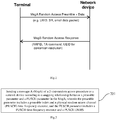
- Fig. 1 is a schematic diagram showing an NR 2-step RA procedure.
- the NR 2-step RA procedure differs from the 4-step RA procedure in that a preamble and data are transmitted simultaneously in a message A (MsgA), wherein content of the data corresponds to the content of the message 3 (Msg3) of the 4-step RA procedure, and the data is based on a physical uplink shared channel (PUSCH) structure.
- MsgA message A
- Msg3 message 3
- PUSCH physical uplink shared channel
- An object of the present disclosure is to provide an information transmission method, apparatus and device, to ensure the correctness of the 2-step RA procedure.
- an embodiment of the present disclosure provides an information transmission method.
- the method is applied to a terminal, and includes:
- mapping relationship includes at least one of:
- the mapping relationship includes the first mapping relationship
- mapping relationship includes the second mapping relationship; and the second mapping relationship includes:
- mapping relationship includes the third mapping relationship
- the method prior to the sending the MsgA of the 2-step random access procedure to the network device according to the mapping relationship between the preamble parameter and the PUSCH parameter in the MsgA, the method further includes:
- the sending the MsgA of the 2-step random access procedure to the network device according to the mapping relationship between the preamble parameter and the PUSCH parameter in the MsgA includes:
- the determining, according to the mapping relationship, the target PUSCH time-frequency resource and the target PUSCH DMRS for sending the MsgA includes:
- the method further includes: receiving a random access response message sent by the network device.
- an embodiment of the present disclosure further provides an information transmission method.
- the method is applied to a network device and includes:
- mapping relationship includes at least one of:
- mapping relationship includes the first mapping relationship; and the first mapping relationship includes:
- mapping relationship includes the second mapping relationship
- mapping relationship includes the third mapping relationship
- the method further includes: sending the mapping relationship between the preamble parameter and the PUSCH parameter in the MsgA of the 2-step random access procedure to the terminal via broadcast signaling or radio resource control (RRC) signaling.
- RRC radio resource control
- the method subsequent to the receiving the MsgA of the 2-step random access procedure sent by the terminal according to the mapping relationship between the preamble parameter and the PUSCH parameter in the MsgA, the method further includes:
- the method further includes: sending a random access response message to the terminal.
- an embodiment of the present disclosure further provides a terminal, including a transceiver, a memory, a processor and a computer program stored in the memory and configured to be executed by the processor, wherein the processor is configured to execute the computer program to implement following steps:
- mapping relationship includes at least one of:
- mapping relationship includes the first mapping relationship; and the first mapping relationship includes:
- mapping relationship includes the second mapping relationship
- mapping relationship includes the third mapping relationship
- the processor is further configured to execute the computer program to implement following steps:
- the processor is further configured to execute the computer program to implement following steps:
- the processor is further configured to execute the computer program to implement following steps:
- the transceiver is configured to: receive a random access response message sent by the network device.
- an embodiment of the present disclosure further provides a terminal, including:
- an embodiment of the present disclosure further provides a network device, including a transceiver, a memory, a processor and a computer program stored in the memory and configured to be executed by the processor, wherein the transceiver is configured to:
- mapping relationship includes at least one of:
- mapping relationship includes the first mapping relationship; and the first mapping relationship includes:
- mapping relationship includes the second mapping relationship
- mapping relationship includes the third mapping relationship
- the transceiver is further configured to: send the mapping relationship between the preamble parameter and the PUSCH parameter in the MsgA of the 2-step random access procedure to the terminal via broadcast signaling or radio resource control (RRC) signaling.
- RRC radio resource control
- the processor is configured to execute the computer program to implement following steps:
- the transceiver is further configured to: send a random access response message to the terminal.
- an embodiment of the present disclosure further provides a network device, including:
- an embodiment of the present disclosure further provides a computer readable storage medium storing thereon a computer program, wherein the computer program is configured to be executed by a processor, to implement the information transmission method, or to implement the steps of the information transmission method.
- a message A (MsgA) of a 2-step random access procedure is sent to a network device according to a mapping relationship between a preamble parameter and a PUSCH parameter in the MsgA; wherein the preamble parameter includes a preamble index and a PRACH time-frequency resource, and the PUSCH parameter includes a PUSCH time-frequency resource and a PUSCH DMRS.
- the preamble parameter includes a preamble index and a PRACH time-frequency resource
- the PUSCH parameter includes a PUSCH time-frequency resource and a PUSCH DMRS.
- an embodiment of the present disclosure provides an information transmission method.
- the method is applied to a terminal, and includes a step 201: sending a message A (MsgA) of a 2-step random access procedure to a network device according to a mapping relationship between a preamble parameter and a PUSCH parameter in the MsgA; wherein the preamble parameter includes a preamble index and a physical random access channel (PRACH) time-frequency resource, and the PUSCH parameter includes a PUSCH time-frequency resource and a PUSCH DMRS.
- MsgA message A
- PRACH physical random access channel
- mapping relationship between the preamble parameter and the PUSCH parameter in the MsgA of the 2-step random access procedure is pre-defined in a protocol or is configured by a network.
- the preamble and the PUSCH in the MsgA adopt the same transmission beam direction.
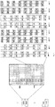
- PUSCH DMRS ports The parameters related to PUSCH DMRS ports are described hereinafter in detail with reference to the schematic diagram, as shown in Fig.3 , illustrating a configuration type of PUSCH DMRS ports when a cyclic prefix-orthogonal frequency division multiplexing (CP-OFDM) waveform is used.
- CP-OFDM cyclic prefix-orthogonal frequency division multiplexing
- the diagram is specifically directed to the configuration type 1 of PUSCH DMRS ports when a CP-OFDM waveform defined in NR is used.
- a case in which 2 OFDM symbols are occupied in time domain is taken as an example, at this time, a maximum quantity of orthogonal DMRS ports that can be supported is 8.
- port 0, port 1, port 4 and port 5 share the same time-frequency resource
- port 2, port 3, port 6 and port 7 share the same time-frequency resource
- the port 0/1/4/5 is separated from the port 2/3/6/7 by frequency division multiplex.
- Frequency domain orthogonal cover code represents that two resource elements (REs) which are spaced apart by one RE in frequency domain are multiplexed in frequency domain by using an orthogonal spread code
- time domain orthogonal cover code represents that two OFDM symbols which are adjacent in time domain are multiplexed in time domain by using an orthogonal spread code
- the port 0, port 1, port 4 and port 5 share the same time-frequency resource, occupy even-numbered REs in one physical resource block (PRB) in frequency domain, occupy two OFDM symbols in time domain, and are further distinguished from each other by FD-OCC with a length of 2 and TD-OCC with a length of 2, specifically as follows:
- the port 2, port 3, port 6 and port 7 share the same time-frequency resource, occupy odd-numbered REs in one PRB in frequency domain, occupy two OFDM symbols in time domain, and are further distinguished from each other by FD-OCC with a length of 2 and TD-OCC with a length of 2, specifically as follows:
- the PUSCH DMRS ports have orthogonal cover code (OCC) parameters.
- a message A (MsgA) of a 2-step random access procedure is sent to a network device according to a mapping relationship between a preamble parameter and a PUSCH parameter in the MsgA; wherein the preamble parameter includes a preamble index and a PRACH time-frequency resource, and the PUSCH parameter includes a PUSCH time-frequency resource and a PUSCH DMRS.
- the preamble parameter includes a preamble index and a PRACH time-frequency resource
- the PUSCH parameter includes a PUSCH time-frequency resource and a PUSCH DMRS.
- mapping relationship includes at least one of:
- mapping relationship includes the first mapping relationship; and the first mapping relationship includes:
- the first mapping relationship is a mapping from the preamble index to ⁇ PUSCH time-frequency resource, PUSCH DMRS ⁇ .
- the base station when receiving a MsgA, firstly the base station needs to perform UE activation detection based on preamble, next uniquely determines a PUSCH channel based on the detected preamble, and then detects the PUSCH channel.
- the mapping from the preamble index to ⁇ PUSCH time-frequency resource, PUSCH DMRS (has to be a one-to-one mapping or a N1(N1 is a positive integer greater than 1)-to-one mapping, instead of a one-to-many mapping.
- N1 preamble indexes in the mapping from the N1 preamble indexes to one PUSCH time-frequency resource may be N1 preamble indexes include by the same Zadoff-Chu (ZC) root sequence, or may be any N1 preamble indexes sequentially numbered.
- ZC Zadoff-Chu
- the first mapping relationship is described in detail below with reference to some examples.
- one preamble index is mapped to one PUSCH time-frequency resource and one PUSCH DMRS, that is, one preamble index to ⁇ PUSCH time-frequency resource, PUSCH DMRS ⁇ .
- preamble#0 is mapped to a combination ⁇ PUSCH #0, DMRS#0 ⁇
- preamble#1 is mapped to a combination ⁇ PUSCH #0, DMRS#1 ⁇ .
- preamble#0 is mapped to a combination ⁇ PUSCH #0, DMRS#0 ⁇
- preamble#1 is mapped to a combination ⁇ PUSCH #1, DMRS#1 ⁇ .
- the preamble#0 and preamble#1 denote a preamble index numbered as 0 and a preamble index numbered as 1, respectively;
- the PUSCH#0 and PUSCH#1 denote a PUSCH time-frequency resource numbered as 0 and a PUSCH time-frequency resource numbered as 1, respectively;
- the DMRS#0 and DMRS#1 denote a PUSCH DMRS numbered as 0 and a PUSCH DMRS numbered as 1, respectively.
- N1 preamble indexes to one ⁇ PUSCH time-frequency resource, PUSCH DMRS ⁇
- one PRACH time-frequency resource supports 64 preamble indexes, as a result, 1 ⁇ N1 ⁇ 64, and the value of parameter N1 should be determined taking account of a mapping from a synchronization signal block (SSB) to a PRACH time-frequency resource RACH occasion (RO).
- SSB synchronization signal block
- RO PRACH occasion
- preamble index values numbered as 0 to 3 are simultaneously mapped to a PUSCH time-frequency resource numbered as 0 (PUSCH#0), and the four preamble indexes (preamble#0/1/2/3) are separately mapped to four DMRSs (DMRS#0/1/2/3) in a one-to-one manner.
- both the PUSCH time-frequency resource numbered as 0 and the PUSCH time-frequency resource numbered as 1 can support virtual uplink multi-user multiple-input multiple-output (MU-MIMO) of 4 UEs.
- MU-MIMO virtual uplink multi-user multiple-input multiple-output
- one preamble index is mapped to one PUSCH DMRS, and one PUSCH time-frequency resource can support N1 users, i.e., virtual uplink MU-MIMO of N1 users is supported.
- both the PUSCH time-frequency resource numbered as 0 and the PUSCH time-frequency resource numbered as 1 (PUSCH#0 and PUSCH#1) can support uplink PUSCH transmission of one UE.
- ceil(N1/T) preamble indexes to one PUSCH DMRS that is, N1 preamble indexes are further divided into T subgroups each including N1/T preamble indexes.
- one PUSCH time-frequency resource can support ceil(N1/T) users, that is, the virtual uplink MU-MIMO of ceil(N1/T) users is supported, wherein T is a positive integer greater than or equal to 1.
- ceil() is a round-up function.
- preamble index values numbered as 0 to 3 are simultaneously mapped to a PUSCH time-frequency resource numbered as 0 (PUSCH#0), two preamble indexes (preamble#0 and preamble#1) are mapped to DMRS#0, and two preamble indexes (preamble#2 and preamble#3) are mapped to DMRS#1; preamble index values numbered as 4 to 7 (preamble#4/5/6/7) are simultaneously mapped to a PUSCH time-frequency resource numbered as 1 (PUSCH#1), two preamble indexes (preamble#4 and preamble#5) are mapped to DMRS#0, and two preamble indexes (preamble#6 and preamble#7) are mapped to DMRS#1.
- PUSCH time-frequency resource numbered as 0 and the PUSCH time-frequency resource numbered as
- mapping relationship includes the second mapping relationship
- the frequency domain offset ⁇ F is pre-defined in a protocol or notified by signaling; the time offset ⁇ T is pre-defined in a protocol or notified by signaling.
- the second mapping relationship is a mapping from the PRACH time-frequency resource to ⁇ PUSCH time-frequency resource, PUSCH DMRS ⁇ .
- the base station when receiving a MsgA, firstly the base station needs to perform UE activation detection based on preamble, next uniquely determines a PUSCH channel based on the detected preamble, and then detects the PUSCH channel.
- the mapping from the PRACH time-frequency resource to ⁇ PUSCH time-frequency resource, PUSCH DMRS (has to be a one-to-one mapping or a N2 (N2 is a positive integer greater than 1)-to-one mapping, instead of a one-to-many mapping.
- the second mapping relationship is described in detail below with reference to some examples.
- one PRACH time-frequency resource is mapped to one PUSCH time-frequency resource and one PUSCH DMRS, that is, one PRACH time-frequency resource to ⁇ PUSCH time-frequency resource, PUSCH DMRS ⁇ .
- PRACH#0 is mapped to a combination ⁇ PUSCH #0, DMRS#0 ⁇
- PRACH#1 is mapped to a combination ⁇ PUSCH #0, DMRS#1 ⁇ .
- PRACH#0 is mapped to a combination ⁇ PUSCH #0, DMRS#0 ⁇
- PRACH#1 is mapped to a combination ⁇ PUSCH #1, DMRS#1 ⁇ .
- the PRACH#0 and PRACH#1 denote a PRACH time-frequency resource numbered as 0 and a PRACH time-frequency resource numbered as 1, respectively;
- the PUSCH#0 and PUSCH#1 denote a PUSCH time-frequency resource numbered as 0 and a PUSCH time-frequency resource numbered as 1, respectively;
- the DMRS#0 and DMRS#1 denote a PUSCH DMRS numbered as 0 and a PUSCH DMRS numbered as 1, respectively.
- the PRACH preamble format 0 defined in NR Rel-15 and a PUSCH channel structure with a subcarrier spacing (SCS) of 15KHz are shown in Fig. 11 .
- a relationship between the PRACH time-frequency resource and the PUSCH time-frequency resource includes (as shown in Fig. 12 ):
- a relationship between the PRACH time-frequency resource and the PUSCH time-frequency resource may further include: in frequency domain, the PRACH time-frequency resource and the PUSCH time-frequency resource have different bandwidths, have unaligned starting PRB locations, and have a fixed frequency domain offset ⁇ F, and in time domain, the PRACH time-frequency resource and the PUSCH time-frequency resource have a fixed time offset ⁇ T.
- the frequency domain offset ⁇ F is pre-defined in a protocol or notified by signaling; the time offset ⁇ T is pre-defined in a protocol or notified by signaling.
- the PRACH time-frequency resource and the PUSCH time-frequency resource are consecutive in time domain, and there is not time offset between the PRACH time-frequency resource and the PUSCH time-frequency resource.
- the PRACH time-frequency resource and the PUSCH time-frequency resource are consecutive in time domain, and there is not time offset between the PRACH time-frequency resource and the PUSCH time-frequency resource.
- the starting PRB location of the PRACH time-frequency resource is spaced from the starting PRB location of the PUSCH time-frequency resource in frequency domain by a fixed frequency domain offset ⁇ F
- the ending time of the preamble time-frequency resource in the MsgA is spaced from the ending time of the PUSCH time-frequency resource in the MsgA in time domain by a fixed time offset AT, where ⁇ T is not 0.
- N2 PRACH time-frequency resources are mapped to one ⁇ PUSCH time-frequency resource, PUSCH DMRS ⁇
- N2 4
- PRACH time-frequency resources numbered as 0 to 3 PRACH#0/1/2/3) are simultaneously mapped to a PUSCH time-frequency resource numbered as 0 (PUSCH#0)
- the four PRACH time-frequency resources (PRACH#0/1/2/3) are simultaneously mapped to a DMRS numbered as 0 (DMRS#0)
- PRACH time-frequency resources numbered as 4 to 7 PRACH#4/5/6/7) are simultaneously mapped to a PUSCH time-frequency resource numbered as 1 (PUSCH#1)
- the four PRACH time-frequency resources (PRACH#4/5/6/7) are simultaneously mapped to a DMRS numbered as 0 (DMRS#0).
- both the PUSCH time-frequency resource numbered as 0 and the PUSCH time-frequency resource numbered as 1 can support virtual uplink MU-MIMO of one UE.
- mapping relationship includes the third mapping relationship
- the third mapping relationship is a mapping from ⁇ preamble index, PRACH time-frequency resource ⁇ to ⁇ PUSCH #1, DMRS#1 ⁇ , in consideration of a mapping from SSB to RO.
- a value of Q is a positive integer selected from 1 to 64; optionally, the value of Q is an integral multiple of 2, or an integral multiple of 4.
- the third mapping relationship includes: S preamble indexes are divided into F second index groups, each of the F second index groups is associated with one SSB and is mapped to one PUSCH time-frequency resource and one PUSCH DMRS, and each of the F second index groups includes one or more consecutive CBRA preamble indexes.
- S/F consecutive CBRA preamble indexes
- fix(x) is a rounding function, which obtains an integer part of x directly.
- the method may further include:
- the step 201 may specifically include:
- the step of sending the MsgA to the network device based on the target PUSCH time-frequency resource and the target PUSCH DMRS may further include: sending the MsgA to the network device based on the one target PRACH time-frequency resource, the one target preamble index, the target PUSCH time-frequency resource and the target PUSCH DMRS.
- the method may further include: receiving a random access response message sent by the network device.
- a message A (MsgA) of a 2-step random access procedure is sent to a network device according to a mapping relationship between a preamble parameter and a PUSCH parameter in the MsgA; wherein the preamble parameter includes a preamble index and a PRACH time-frequency resource, and the PUSCH parameter includes a PUSCH time-frequency resource and a PUSCH DMRS.
- the preamble parameter includes a preamble index and a PRACH time-frequency resource
- the PUSCH parameter includes a PUSCH time-frequency resource and a PUSCH DMRS.
- an embodiment of the present disclosure provides an information transmission method.
- the method is applied to a network device, and includes a step 1501: receiving a message A (MsgA) of a 2-step random access procedure sent by a terminal according to a mapping relationship between a preamble parameter and a physical uplink shared channel (PUSCH) parameter in the MsgA; wherein the preamble parameter includes a preamble index and a physical random access channel (PRACH) time-frequency resource, and the PUSCH parameter includes a PUSCH time-frequency resource and a PUSCH demodulation reference signal (DMRS).
- MsgA message A
- PUSCH physical uplink shared channel
- mapping relationship between the preamble parameter and the PUSCH parameter in the MsgA of the 2-step random access procedure is pre-defined in a protocol or is configured by a network.
- a message A (MsgA) of a 2-step random access procedure sent by a terminal according to a mapping relationship between a preamble parameter and a PUSCH parameter in the MsgA is received; wherein the preamble parameter includes a preamble index and a PRACH time-frequency resource, and the PUSCH parameter includes a PUSCH time-frequency resource and a PUSCH DMRS.
- the preamble parameter includes a preamble index and a PRACH time-frequency resource
- the PUSCH parameter includes a PUSCH time-frequency resource and a PUSCH DMRS.
- mapping relationship includes at least one of:
- mapping relationship includes the first mapping relationship; and the first mapping relationship includes:
- the first mapping relationship is a mapping from the preamble index to ⁇ PUSCH time-frequency resource, PUSCH DMRS ⁇
- mapping relationship includes the second mapping relationship
- the second mapping relationship is a mapping from the PRACH time-frequency resource to ⁇ PUSCH time-frequency resource, PUSCH DMRS ⁇ .
- mapping relationship includes the third mapping relationship
- the third mapping relationship is a mapping from ⁇ preamble index, PRACH time-frequency resource ⁇ to ⁇ PUSCH #1, DMRS#1 ⁇ , in consideration of a mapping from SSB to RO.
- the method may further include: sending the mapping relationship between the preamble parameter and the PUSCH parameter in the MsgA of the 2-step random access procedure to the terminal via broadcast signaling or radio resource control signaling.
- the network device notifies UE in an idle (RRC_IDLE) state or an inactive (RRC_INACTIVE) state by using a broadcast message SIB1 (system information block1); the network device notifies UE in a connected (RRC_CONNECTED) state by using RRC signaling.
- RRC_IDLE idle
- RRC_INACTIVE inactive
- SIB1 system information block1
- the method may further include:
- the method may further include: sending a random access response message to the terminal.
- a message A (MsgA) of a 2-step random access procedure sent by a terminal according to a mapping relationship between a preamble parameter and a PUSCH parameter in the MsgA is received; wherein the preamble parameter includes a preamble index and a PRACH time-frequency resource, and the PUSCH parameter includes a PUSCH time-frequency resource and a PUSCH DMRS.
- the preamble parameter includes a preamble index and a PRACH time-frequency resource
- the PUSCH parameter includes a PUSCH time-frequency resource and a PUSCH DMRS.
- an embodiment of the present disclosure further provides a terminal.
- the terminal includes: a memory 1620, a processor 1600, a transceiver 1610, a bus interface and a computer program stored in the memory 1620 and configured to be executed by the processor 1600, wherein the processor 1600 is configured to read the computer program in the memory 1620 to implement following process:
- a bus architecture may include any number of interconnected buses and bridges, and connects various circuits including one or more processors represented by the processor 1600 and memory represented by the memory 1620.
- the bus architecture may also connect various other circuits such as peripherals, voltage regulators and power management circuits, which is well known in the art. Therefore, a detailed description thereof is omitted herein.
- a bus interface provides an interface.
- the transceiver 1610 may be multiple elements, such as a transmitter and a receiver, to allow for communication with various other apparatuses on the transmission medium.
- the user interface 1630 may be an interface capable of externally or internally connecting a required device, and the connected device includes, but is not limited to: a keypad, a display, a speaker, a microphone, a joystick and the like.
- the processor 1600 is responsible for supervising the bus architecture and normal operation and the memory 1620 may store the data being used by the processor 1600 during operation.
- mapping relationship includes at least one of:
- mapping relationship includes the first mapping relationship; and the first mapping relationship includes:
- mapping relationship includes the second mapping relationship
- mapping relationship includes the third mapping relationship
- processor 1600 is further configured to execute the computer program to implement following steps:
- processor 1600 is further configured to execute the computer program to implement following steps:
- processor 1600 is further configured to execute the computer program to implement following steps:
- the transceiver 1610 is configured to: receive a random access response message sent by the network device.
- an embodiment of the present disclosure further provides a terminal.
- the terminal includes:
- mapping relationship includes at least one of:
- mapping relationship includes the first mapping relationship; and the first mapping relationship includes:
- mapping relationship includes the second mapping relationship
- mapping relationship includes the third mapping relationship
- the first sending module 1701 may include:
- the processing unit is specifically configured to:
- the terminal further includes: a third receiving module, configured to receive a random access response message sent by the network device.
- a message A (MsgA) of a 2-step random access procedure is sent by the first sending module to a network device according to a mapping relationship between a preamble parameter and a PUSCH parameter in the MsgA; wherein the preamble parameter includes a preamble index and a PRACH time-frequency resource, and the PUSCH parameter includes a PUSCH time-frequency resource and a PUSCH DMRS.
- the preamble parameter includes a preamble index and a PRACH time-frequency resource
- the PUSCH parameter includes a PUSCH time-frequency resource and a PUSCH DMRS.
- a computer readable storage medium storing thereon a computer program is further provided, wherein the computer program is configured to be executed by a processor to implement following steps:
- an embodiment of the present disclosure further provides a network device.
- the network device includes: a transceiver 1810, a memory 1820, a processor 18008 and a computer program stored in the memory and configured to be executed by the processor, wherein the transceiver 1810 is configured to:
- a bus architecture may include any number of interconnected buses and bridges, and connects various circuits including one or more processors represented by the processor 1800 and memory represented by the memory 1820.
- the bus architecture may also connect various other circuits such as peripherals, voltage regulators and power management circuits, which is well known in the art. Therefore, a detailed description thereof is omitted herein.
- a bus interface provides an interface.
- the transceiver 1810 may be multiple elements, such as a transmitter and a receiver, to allow for communication with various other apparatuses on the transmission medium.
- the processor 1800 is responsible for supervising the bus architecture and normal operation and the memory 1820 may store the data being used by the processor 1800 during operation.
- mapping relationship includes at least one of:
- mapping relationship includes the first mapping relationship; and the first mapping relationship includes:
- mapping relationship includes the second mapping relationship
- mapping relationship includes the third mapping relationship
- the transceiver 1810 is further configured to: send the mapping relationship between the preamble parameter and the PUSCH parameter in the MsgA of the 2-step random access procedure to the terminal via broadcast signaling or radio resource control signaling.
- processor 1800 is configured to execute the computer program to implement following steps:
- the transceiver 1810 is further configured to: send a random access response message to the terminal.
- an embodiment of the present disclosure further provides a network device.
- the network device includes:
- mapping relationship includes at least one of:
- mapping relationship includes the first mapping relationship; and the first mapping relationship includes:
- mapping relationship includes the second mapping relationship
- mapping relationship includes the third mapping relationship
- the network device may further include: a second sending module, configured to send the mapping relationship between the preamble parameter and the PUSCH parameter in the MsgA of the 2-step random access procedure to the terminal via broadcast signaling or radio resource control signaling.
- a second sending module configured to send the mapping relationship between the preamble parameter and the PUSCH parameter in the MsgA of the 2-step random access procedure to the terminal via broadcast signaling or radio resource control signaling.
- the network device may further include: a third sending module, configured to send a random access response message to the terminal.
- a message A (MsgA) of a 2-step random access procedure sent by a terminal according to a mapping relationship between a preamble parameter and a PUSCH parameter in the MsgA is received by a first receiving module; wherein the preamble parameter includes a preamble index and a PRACH time-frequency resource, and the PUSCH parameter includes a PUSCH time-frequency resource and a PUSCH DMRS.
- the preamble parameter includes a preamble index and a PRACH time-frequency resource
- the PUSCH parameter includes a PUSCH time-frequency resource and a PUSCH DMRS.
- a computer readable storage medium storing thereon a computer program is further provided, wherein the computer program is configured to be executed by a processor to implement following steps:
- the computer readable medium includes permanent and non-permanent, removable and non-removable media, and may achieve information storage by any means or techniques.
- Information may be computer readable instruction, data structure, program module or other data.
- Computer storage medium may, for example, include, but is not limited to: phase change random access memory (PRAM), static random access memory (SRAM), dynamic random access memory (DRAM), other types of random access memory (RAM), read-only memory (ROM), electrically erasable programmable read-only memory (EEPROM), flash memory or other memory technologies, compact disc read-only memory (CD-ROM), digital versatile disc (DVD) or other optical storages, cassette tape, magnetic tape, magnetic disk or other magnetic storage device or any other non-transmitting medium, which is configured to store information accessible by a computing device.
- the computer readable medium does not include transitory media, such as modulated data signals and carriers.
- the terminal described in this description includes, but is not limited to: a smart phone, tablet computer or the like, and many described functional parts are referred to as a module, to emphasize the independence of their implementations.
- a module may be implemented in software, so as to be executed by various types of processors.
- an identified executable code module may include one or more physical or logical blocks of computer instructions, for example, they may be built as objects, processes or functions. Nevertheless, the executable codes of the identified module need not to reside in a same location; rather, the identified module may include different instructions stored at different locations, and when combined logically, these instructions form the module and fulfill the specified purpose of the module.
- the executable code module may be an instruction or multiple instructions, and may even be distributed over multiple distinct code segments, over different programs, or over multiple storage devices.
- operation data may be identified in the module, implemented in any suitable manner and organized in any suitable type of data structure. The operation data may be gathered as a single data set, or may be distributed over different locations (including different storage devices), and at least a part of the operation data may only reside in a system or network as an electronic signal.
- a module may be implemented in software, considering the hardware process level in the related art, a person skilled in the art may construct hardware corresponding to all modules that can be implemented in software, to achieve corresponding functions, if cost is not considered.
- the hardware circuit includes normal very large scale integration (VLSI) circuit or gate array, and semiconductor devices in the relate art such as logic chip or transistor, or other discrete devices.
- VLSI very large scale integration
- the module may also be implemented with a programmable hardware device, such as field program gate array, programmable logic array or programmable logic device.
- modules, unit, sub-module or subunit may be implemented in one or more application specific integrated circuits (ASICs), a digital signal processor (DSP), a DSP device (DSPD), a programmable logic device (PLD), a field-programmable gate array (FPGA), a general-purpose processor, a controller, a microcontroller, a microprocessor, other electronic unit configured to perform the functions in the present disclosure or a combination thereof.
- ASICs application specific integrated circuits
- DSP digital signal processor
- DSPD DSP device
- PLD programmable logic device
- FPGA field-programmable gate array
- general-purpose processor a controller, a microcontroller, a microprocessor, other electronic unit configured to perform the functions in the present disclosure or a combination thereof.
- the techniques in some embodiments of the present disclosure may be implemented by modules (for example, processes or functions) performing the functions described in embodiments of the present disclosure.
- Software codes may be stored in a memory and executed by a processor.
- the memory may be implemented internal or external to a processor.
Landscapes
- Engineering & Computer Science (AREA)
- Signal Processing (AREA)
- Computer Networks & Wireless Communication (AREA)
- Mobile Radio Communication Systems (AREA)
Abstract
Description
- The present application claims priority to the
Chinese patent application No. 201910115175.X filed in China on February 14, 2019 - The present disclosure relates to the field of communication technologies, in particular to an information transmission method, apparatus and device.
- In the related art, long term evolution (LTE) protocols adopt a 4-step random access (RA) procedure. However, the 4-step RA procedure would cause significant control plane latency in 5th Generation mobile communication system (5G) New Radio (NR) uplink (UL) multi-beam physical random access channel (PRACH) transmission, thus the low-latency oriented performance target defined for ultra-reliable and low latency communications (URLLC) scenarios cannot be reached. In order to obtain a processing method that effective reduces the control plane processing latency, NR Rel-16 in the related art has set up the work item of 2-step RA procedure.
-
Fig. 1 is a schematic diagram showing an NR 2-step RA procedure. The NR 2-step RA procedure differs from the 4-step RA procedure in that a preamble and data are transmitted simultaneously in a message A (MsgA), wherein content of the data corresponds to the content of the message 3 (Msg3) of the 4-step RA procedure, and the data is based on a physical uplink shared channel (PUSCH) structure. As such, how to ensure the correctness of the 2-step RA procedure becomes a problem demanding prompt resolution. - An object of the present disclosure is to provide an information transmission method, apparatus and device, to ensure the correctness of the 2-step RA procedure.
- To achieve the above object, an embodiment of the present disclosure provides an information transmission method. The method is applied to a terminal, and includes:
- sending a message A (MsgA) of a 2-step random access procedure to a network device according to a mapping relationship between a preamble parameter and a physical uplink shared channel (PUSCH) parameter in the MsgA;
- wherein the preamble parameter includes a preamble index and a physical random access channel (PRACH) time-frequency resource, and the PUSCH parameter includes a PUSCH time-frequency resource and a PUSCH demodulation reference signal (DMRS).
- Optionally, the mapping relationship includes at least one of:
- a first mapping relationship of the preamble index to the PUSCH time-frequency resource and the PUSCH DMRS;
- a second mapping relationship of the PRACH time-frequency resource to the PUSCH time-frequency resource and the PUSCH DMRS;
- a third mapping relationship of a combination of the preamble index and the PRACH time-frequency resource to the PUSCH time-frequency resource and the PUSCH DMRS.
- Optionally, the mapping relationship includes the first mapping relationship; and
- the first mapping relationship includes:
- one preamble index is mapped to one PUSCH time-frequency resource and one PUSCH DMRS; or,
- N preamble indexes are mapped to one PUSCH time-frequency resource, and each of the N preamble indexes is mapped to one PUSCH DMRS on the one PUSCH time-frequency resource to which the N preamble indexes are mapped; or,
- M preamble indexes are mapped to one PUSCH DMRS on one PUSCH time-frequency resource; or,
- K preamble indexes are mapped to one PUSCH time-frequency resource, the K preamble indexes being divided into L first index groups, and each of the L first index groups is mapped to one PUSCH DMRS on the one PUSCH time-frequency resource to which the K preamble indexes are mapped, wherein the L first index groups each include at least one preamble index;
- wherein, each of N, M and K is a positive integer greater than 1, and L is a positive integer greater than or equal to 1.
- Optionally, the mapping relationship includes the second mapping relationship; and the second mapping relationship includes:
- T PRACH time-frequency resources are mapped to one PUSCH DMRS on one PUSCH time-frequency resource, wherein T is a positive integer greater than 1; or,
- one PRACH time-frequency resource is mapped to one PUSCH time-frequency resource and one PUSCH DMRS;
- wherein a relationship between the PRACH time-frequency resource and the PUSCH time-frequency resource includes:
- in frequency domain, the PRACH time-frequency resource and the PUSCH time-frequency resource have a same bandwidth, and have aligned starting physical resource block (PRB) locations; or,
- in frequency domain, the PRACH time-frequency resource and the PUSCH time-frequency resource have different bandwidths, and have aligned central PRB locations; or,
- in frequency domain, the PRACH time-frequency resource and the PUSCH time-frequency resource have different bandwidths, and have aligned starting PRB locations; or,
- in frequency domain, the PRACH time-frequency resource and the PUSCH time-frequency resource have different bandwidths, have unaligned starting PRB locations, and have a fixed frequency domain offset ΔF, and in time domain, the PRACH time-frequency resource and the PUSCH time-frequency resource have a fixed time offset ΔT.
- Optionally, the mapping relationship includes the third mapping relationship; and
- in a case that one synchronization signal block (SSB) is mapped to 1/Y RACH occasions (ROs), the third mapping relationship includes:
- the 1/Y ROs are mapped to one PUSCH time-frequency resource and one PUSCH DMRS; or,
- one RO is mapped to one PUSCH time-frequency resource and one PUSCH DMRS; or,
- Q preamble indexes in one RO are mapped to one PUSCH time-frequency resource and one PUSCH DMRS;
- in a case that one SSB is mapped to one RO, the third mapping relationship includes:
- one RO is mapped to one PUSCH time-frequency resource and one PUSCH DMRS; or,
- H preamble indexes in one RO are mapped to one PUSCH time-frequency resource and one PUSCH DMRS;
- in a case that W SSBs are mapped to one RO, the third mapping relationship includes:
- R consecutive contention based random access (CBRA) preamble indexes are associated with a first SSB, and are mapped to one PUSCH time-frequency resource and one PUSCH DMRS; or,
- S preamble indexes are divided into F second index groups, each of the F second index groups is associated with one SSB and is mapped to one PUSCH time-frequency resource and one PUSCH DMRS, and each of the F second index groups includes one or more consecutive CBRA preamble indexes;
- Optionally, prior to the sending the MsgA of the 2-step random access procedure to the network device according to the mapping relationship between the preamble parameter and the PUSCH parameter in the MsgA, the method further includes:
- receiving broadcast signaling or radio resource control (RRC) signaling sent by the network device;
- obtaining the mapping relationship between the preamble parameter and the PUSCH parameter in the MsgA according to the broadcast signaling or the RRC signaling.
- Optionally, the sending the MsgA of the 2-step random access procedure to the network device according to the mapping relationship between the preamble parameter and the PUSCH parameter in the MsgA includes:
- determining, according to the mapping relationship, a target PUSCH time-frequency resource and a target PUSCH DMRS for sending the MsgA; and
- sending the MsgA to the network device based on the target PUSCH time-frequency resource and the target PUSCH DMRS.
- Optionally, the determining, according to the mapping relationship, the target PUSCH time-frequency resource and the target PUSCH DMRS for sending the MsgA includes:
- obtaining a configuration resource set including the PRACH time-frequency resource and the preamble index;
- selecting one target PRACH time-frequency resource and one target preamble index from the configuration resource set; and
- determining, according to the mapping relationship, the target PUSCH time-frequency resource and the target PUSCH DMRS corresponding to the one target PRACH time-frequency resource and/or the one target preamble index;
- the sending the MsgA to the network device based on the target PUSCH time-frequency resource and the target PUSCH DMRS includes:
sending the MsgA to the network device based on the one target PRACH time-frequency resource, the one target preamble index, the target PUSCH time-frequency resource and the target PUSCH DMRS. - Optionally, subsequent to the sending the MsgA of the 2-step random access procedure to the network device according to the mapping relationship between the preamble parameter and the PUSCH parameter in the MsgA, the method further includes:
receiving a random access response message sent by the network device. - To achieve the foregoing object, an embodiment of the present disclosure further provides an information transmission method. The method is applied to a network device and includes:
- receiving a message A (MsgA) of a 2-step random access procedure sent by a terminal according to a mapping relationship between a preamble parameter and a physical uplink shared channel (PUSCH) parameter in the MsgA;
- wherein the preamble parameter includes a preamble index and a physical random access channel (PRACH) time-frequency resource, and the PUSCH parameter includes a PUSCH time-frequency resource and a PUSCH demodulation reference signal (DMRS).
- Optionally, the mapping relationship includes at least one of:
- a first mapping relationship of the preamble index to the PUSCH time-frequency resource and the PUSCH DMRS;
- a second mapping relationship of the PRACH time-frequency resource to the PUSCH time-frequency resource and the PUSCH DMRS;
- a third mapping relationship of a combination of the preamble index and the PRACH time-frequency resource to the PUSCH time-frequency resource and the PUSCH DMRS.
- Optionally, the mapping relationship includes the first mapping relationship; and
the first mapping relationship includes: - one preamble index is mapped to one PUSCH time-frequency resource and one PUSCH DMRS; or,
- N preamble indexes are mapped to one PUSCH time-frequency resource, and each of the N preamble indexes is mapped to one PUSCH DMRS on the one PUSCH time-frequency resource to which the N preamble indexes are mapped; or,
- M preamble indexes are mapped to one PUSCH DMRS on one PUSCH time-frequency resource; or,
- K preamble indexes are mapped to one PUSCH time-frequency resource, the K preamble indexes being divided into L first index groups, and each of the L first index groups is mapped to one PUSCH DMRS on the one PUSCH time-frequency resource to which the K preamble indexes are mapped, wherein the L first index groups each include at least one preamble index;
- Optionally, the mapping relationship includes the second mapping relationship; and
- the second mapping relationship includes:
- T PRACH time-frequency resources are mapped to one PUSCH DMRS on one PUSCH time-frequency resource, wherein T is a positive integer greater than 1; or,
- one PRACH time-frequency resource is mapped to one PUSCH time-frequency resource and one PUSCH DMRS;
- wherein a relationship between the PRACH time-frequency resource and the PUSCH time-frequency resource includes:
- in frequency domain, the PRACH time-frequency resource and the PUSCH time-frequency resource have a same bandwidth, and have aligned starting physical resource block (PRB) locations; or,
- in frequency domain, the PRACH time-frequency resource and the PUSCH time-frequency resource have different bandwidths, and have aligned central PRB locations; or,
- in frequency domain, the PRACH time-frequency resource and the PUSCH time-frequency resource have different bandwidths, and have aligned starting PRB locations; or,
- in frequency domain, the PRACH time-frequency resource and the PUSCH time-frequency resource have different bandwidths, have unaligned starting PRB locations, and have a fixed frequency domain offset ΔF, and in time domain, the PRACH time-frequency resource and the PUSCH time-frequency resource have a fixed time offset ΔT.
- Optionally, the mapping relationship includes the third mapping relationship; and
- in a case that one synchronization signal block (SSB) is mapped to 1/Y RACH occasions (ROs), the third mapping relationship includes:
- the 1/Y ROs are mapped to one PUSCH time-frequency resource and one PUSCH DMRS; or,
- one RO is mapped to one PUSCH time-frequency resource and one PUSCH DMRS; or,
- Q preamble indexes in one RO are mapped to one PUSCH time-frequency resource and one PUSCH DMRS;
- in a case that one SSB is mapped to one RO, the third mapping relationship includes:
- one RO is mapped to one PUSCH time-frequency resource and one PUSCH DMRS; or,
- H preamble indexes in one RO are mapped to one PUSCH time-frequency resource and one PUSCH DMRS;
- in a case that W SSBs are mapped to one RO, the third mapping relationship includes:
- R consecutive contention based random access (CBRA) preamble indexes are associated with a first SSB, and are mapped to one PUSCH time-frequency resource and one PUSCH DMRS; or,
- S preamble indexes are divided into F second index groups, each of the F second index groups is associated with one SSB and is mapped to one PUSCH time-frequency resource and one PUSCH DMRS, and each of the F second index groups includes one or more consecutive CBRA preamble indexes;
- wherein, Y is less than 1; Q, H, F are a positive integer greater than or equal to 1; W, R, S are a positive integer greater than 1.
- Optionally, prior to the receiving the MsgA of the 2-step random access procedure sent by the terminal according to the mapping relationship between the preamble parameter and the PUSCH parameter in the MsgA, the method further includes:
sending the mapping relationship between the preamble parameter and the PUSCH parameter in the MsgA of the 2-step random access procedure to the terminal via broadcast signaling or radio resource control (RRC) signaling. - Optionally, subsequent to the receiving the MsgA of the 2-step random access procedure sent by the terminal according to the mapping relationship between the preamble parameter and the PUSCH parameter in the MsgA, the method further includes:
- performing PRACH preamble detection on the PRACH time-frequency resource;
- in a case that a preamble is detected, obtaining, according to the mapping relationship, a target PUSCH time-frequency resource and a target PUSCH DMRS corresponding to a target PRACH time-frequency resource and/or a target preamble index selected by the terminal; and
- performing PUSCH channel detection based on the target PUSCH time-frequency resource and the target PUSCH DMRS.
- Optionally, subsequent to the receiving the MsgA of the 2-step random access procedure sent by the terminal according to the mapping relationship between the preamble parameter and the PUSCH parameter in the MsgA, the method further includes:
sending a random access response message to the terminal. - To achieve the foregoing object, an embodiment of the present disclosure further provides a terminal, including a transceiver, a memory, a processor and a computer program stored in the memory and configured to be executed by the processor, wherein the processor is configured to execute the computer program to implement following steps:
- sending a message A (MsgA) of a 2-step random access procedure to a network device according to a mapping relationship between a preamble parameter and a physical uplink shared channel (PUSCH) parameter in the MsgA;
- wherein the preamble parameter includes a preamble index and a physical random access channel (PRACH) time-frequency resource, and the PUSCH parameter includes a PUSCH time-frequency resource and a PUSCH demodulation reference signal (DMRS).
- Optionally, the mapping relationship includes at least one of:
- a first mapping relationship of the preamble index to the PUSCH time-frequency resource and the PUSCH DMRS;
- a second mapping relationship of the PRACH time-frequency resource to the PUSCH time-frequency resource and the PUSCH DMRS;
- a third mapping relationship of a combination of the preamble index and the PRACH time-frequency resource to the PUSCH time-frequency resource and the PUSCH DMRS.
- Optionally, the mapping relationship includes the first mapping relationship; and
the first mapping relationship includes: - one preamble index is mapped to one PUSCH time-frequency resource and one PUSCH DMRS; or,
- N preamble indexes are mapped to one PUSCH time-frequency resource, and each of the N preamble indexes is mapped to one PUSCH DMRS on the one PUSCH time-frequency resource to which the N preamble indexes are mapped; or,
- M preamble indexes are mapped to one PUSCH DMRS on one PUSCH time-frequency resource; or,
- K preamble indexes are mapped to one PUSCH time-frequency resource, the K preamble indexes being divided into L first index groups, and each of the L first index groups is mapped to one PUSCH DMRS on the one PUSCH time-frequency resource to which the K preamble indexes are mapped, wherein the L first index groups each include at least one preamble index;
- Optionally, the mapping relationship includes the second mapping relationship; and
- the second mapping relationship includes:
- T PRACH time-frequency resources are mapped to one PUSCH DMRS on one PUSCH time-frequency resource, wherein T is a positive integer greater than 1; or,
- one PRACH time-frequency resource is mapped to one PUSCH time-frequency resource and one PUSCH DMRS;
- wherein a relationship between the PRACH time-frequency resource and the PUSCH time-frequency resource includes:
- in frequency domain, the PRACH time-frequency resource and the PUSCH time-frequency resource have a same bandwidth, and have aligned starting physical resource block (PRB) locations; or,
- in frequency domain, the PRACH time-frequency resource and the PUSCH time-frequency resource have different bandwidths, and have aligned central PRB locations; or,
- in frequency domain, the PRACH time-frequency resource and the PUSCH time-frequency resource have different bandwidths, and have aligned starting PRB locations; or,
- in frequency domain, the PRACH time-frequency resource and the PUSCH time-frequency resource have different bandwidths, have unaligned starting PRB locations, and have a fixed frequency domain offset ΔF, and in time domain, the PRACH time-frequency resource and the PUSCH time-frequency resource have a fixed time offset ΔT.
- Optionally, the mapping relationship includes the third mapping relationship; and
- in a case that one synchronization signal block (SSB) is mapped to 1/Y RACH occasions (ROs), the third mapping relationship includes:
- the 1/Y ROs are mapped to one PUSCH time-frequency resource and one PUSCH DMRS; or,
- one RO is mapped to one PUSCH time-frequency resource and one PUSCH DMRS; or,
- Q preamble indexes in one RO are mapped to one PUSCH time-frequency resource and one PUSCH DMRS;
- in a case that one SSB is mapped to one RO, the third mapping relationship includes:
- one RO is mapped to one PUSCH time-frequency resource and one PUSCH DMRS; or,
- H preamble indexes in one RO are mapped to one PUSCH time-frequency resource and one PUSCH DMRS;
- in a case that W SSBs are mapped to one RO, the third mapping relationship includes:
- R consecutive contention based random access (CBRA) preamble indexes are associated with a first SSB, and are mapped to one PUSCH time-frequency resource and one PUSCH DMRS; or,
- S preamble indexes are divided into F second index groups, each of the F second index groups is associated with one SSB and is mapped to one PUSCH time-frequency resource and one PUSCH DMRS, and each of the F second index groups includes one or more consecutive CBRA preamble indexes;
- Optionally, the processor is further configured to execute the computer program to implement following steps:
- receiving broadcast signaling or radio resource control (RRC) signaling sent by the network device;
- obtaining the mapping relationship between the preamble parameter and the PUSCH parameter in the MsgA according to the broadcast signaling or the RRC signaling.
- Optionally, the processor is further configured to execute the computer program to implement following steps:
- determining, according to the mapping relationship, a target PUSCH time-frequency resource and a target PUSCH DMRS for sending the MsgA; and
- sending the MsgA to the network device based on the target PUSCH time-frequency resource and the target PUSCH DMRS.
- Optionally, the processor is further configured to execute the computer program to implement following steps:
- obtaining a configuration resource set including the PRACH time-frequency resource and the preamble index;
- selecting one target PRACH time-frequency resource and one target preamble index from the configuration resource set;
- determining, according to the mapping relationship, the target PUSCH time-frequency resource and the target PUSCH DMRS corresponding to the one target PRACH time-frequency resource and/or the one target preamble index;
- sending the MsgA to the network device based on the one target PRACH time-frequency resource, the one target preamble index, the target PUSCH time-frequency resource and the target PUSCH DMRS.
- Optionally, the transceiver is configured to: receive a random access response message sent by the network device.
- To achieve the foregoing object, an embodiment of the present disclosure further provides a terminal, including:
- a first sending module, configured to send a message A (MsgA) of a 2-step random access procedure to a network device according to a mapping relationship between a preamble parameter and a physical uplink shared channel (PUSCH) parameter in the MsgA;
- wherein the preamble parameter includes a preamble index and a physical random access channel (PRACH) time-frequency resource, and the PUSCH parameter includes a PUSCH time-frequency resource and a PUSCH demodulation reference signal (DMRS).
- To achieve the foregoing object, an embodiment of the present disclosure further provides a network device, including a transceiver, a memory, a processor and a computer program stored in the memory and configured to be executed by the processor, wherein the transceiver is configured to:
- receive a message A (MsgA) of a 2-step random access procedure sent by a terminal according to a mapping relationship between a preamble parameter and a physical uplink shared channel (PUSCH) parameter in the MsgA;
- wherein the preamble parameter includes a preamble index and a physical random access channel (PRACH) time-frequency resource, and the PUSCH parameter includes a PUSCH time-frequency resource and a PUSCH demodulation reference signal (DMRS).
- Optionally, the mapping relationship includes at least one of:
- a first mapping relationship of the preamble index to the PUSCH time-frequency resource and the PUSCH DMRS;
- a second mapping relationship of the PRACH time-frequency resource to the PUSCH time-frequency resource and the PUSCH DMRS;
- a third mapping relationship of a combination of the preamble index and the PRACH time-frequency resource to the PUSCH time-frequency resource and the PUSCH DMRS.
- Optionally, the mapping relationship includes the first mapping relationship; and
the first mapping relationship includes: - one preamble index is mapped to one PUSCH time-frequency resource and one PUSCH DMRS; or,
- N preamble indexes are mapped to one PUSCH time-frequency resource, and each of the N preamble indexes is mapped to one PUSCH DMRS on the one PUSCH time-frequency resource to which the N preamble indexes are mapped; or,
- M preamble indexes are mapped to one PUSCH DMRS on one PUSCH time-frequency resource; or,
- K preamble indexes are mapped to one PUSCH time-frequency resource, the K preamble indexes being divided into L first index groups, and each of the L first index groups is mapped to one PUSCH DMRS on the one PUSCH time-frequency resource to which the K preamble indexes are mapped, wherein the L first index groups each include at least one preamble index;
- Optionally, the mapping relationship includes the second mapping relationship; and
- the second mapping relationship includes:
- T PRACH time-frequency resources are mapped to one PUSCH DMRS on one PUSCH time-frequency resource, wherein T is a positive integer greater than 1; or,
- one PRACH time-frequency resource is mapped to one PUSCH time-frequency resource and one PUSCH DMRS;
- wherein a relationship between the PRACH time-frequency resource and the PUSCH time-frequency resource includes:
- in frequency domain, the PRACH time-frequency resource and the PUSCH time-frequency resource have a same bandwidth, and have aligned starting physical resource block (PRB) locations; or,
- in frequency domain, the PRACH time-frequency resource and the PUSCH time-frequency resource have different bandwidths, and have aligned central PRB locations; or,
- in frequency domain, the PRACH time-frequency resource and the PUSCH time-frequency resource have different bandwidths, and have aligned starting PRB locations; or,
- in frequency domain, the PRACH time-frequency resource and the PUSCH time-frequency resource have different bandwidths, have unaligned starting PRB locations, and have a fixed frequency domain offset ΔF, and in time domain, the PRACH time-frequency resource and the PUSCH time-frequency resource have a fixed time offset ΔT.
- Optionally, the mapping relationship includes the third mapping relationship; and
- in a case that one synchronization signal block (SSB) is mapped to 1/Y RACH occasions (ROs), the third mapping relationship includes:
- the 1/Y ROs are mapped to one PUSCH time-frequency resource and one PUSCH DMRS; or,
- one RO is mapped to one PUSCH time-frequency resource and one PUSCH DMRS; or,
- Q preamble indexes in one RO are mapped to one PUSCH time-frequency resource and one PUSCH DMRS;
- in a case that one SSB is mapped to one RO, the third mapping relationship includes:
- one RO is mapped to one PUSCH time-frequency resource and one PUSCH DMRS; or,
- H preamble indexes in one RO are mapped to one PUSCH time-frequency resource and one PUSCH DMRS;
- in a case that W SSBs are mapped to one RO, the third mapping relationship includes:
- R consecutive contention based random access (CBRA) preamble indexes are associated with a first SSB, and are mapped to one PUSCH time-frequency resource and one PUSCH DMRS; or,
- S preamble indexes are divided into F second index groups, each of the F second index groups is associated with one SSB and is mapped to one PUSCH time-frequency resource and one PUSCH DMRS, and each of the F second index groups includes one or more consecutive CBRA preamble indexes;
- Optionally, the transceiver is further configured to:
send the mapping relationship between the preamble parameter and the PUSCH parameter in the MsgA of the 2-step random access procedure to the terminal via broadcast signaling or radio resource control (RRC) signaling. - Optionally, the processor is configured to execute the computer program to implement following steps:
- performing PRACH preamble detection on the PRACH time-frequency resource;
- in a case that a preamble is detected, obtaining, according to the mapping relationship, a target PUSCH time-frequency resource and a target PUSCH DMRS corresponding to a target PRACH time-frequency resource and/or a target preamble index selected by the terminal; and
- performing PUSCH channel detection based on the target PUSCH time-frequency resource and the target PUSCH DMRS.
- Optionally, the transceiver is further configured to: send a random access response message to the terminal.
- To achieve the foregoing object, an embodiment of the present disclosure further provides a network device, including:
- a first receiving module, configured to receive a message A (MsgA) of a 2-step random access procedure sent by a terminal according to a mapping relationship between a preamble parameter and a physical uplink shared channel (PUSCH) parameter in the MsgA;
- wherein the preamble parameter includes a preamble index and a physical random access channel (PRACH) time-frequency resource, and the PUSCH parameter includes a PUSCH time-frequency resource and a PUSCH demodulation reference signal (DMRS).
- To achieve the foregoing object, an embodiment of the present disclosure further provides a computer readable storage medium storing thereon a computer program, wherein the computer program is configured to be executed by a processor, to implement the information transmission method, or to implement the steps of the information transmission method.
- The foregoing technical solutions of the present disclosure have at least the following beneficial effects.
- In the foregoing technical solutions of the embodiments of the present disclosure, a message A (MsgA) of a 2-step random access procedure is sent to a network device according to a mapping relationship between a preamble parameter and a PUSCH parameter in the MsgA; wherein the preamble parameter includes a preamble index and a PRACH time-frequency resource, and the PUSCH parameter includes a PUSCH time-frequency resource and a PUSCH DMRS. In this way, the correctness of the 2-step RA procedure can be ensured, thus an effect of effectively reducing the control plane processing latency of uplink multi-beam physical random access channel transmission can be achieved.
-
-
Fig. 1 is a flow diagram of a 2-step RA procedure in the related art; -
Fig.2 is a first flow diagram of an information transmission method according to an embodiment of the present disclosure; -
Fig.3 is a schematic diagram illustrating a configuration type of PUSCH DMRS ports when a CP-OFDM waveform is used; -
Fig.4 is a first schematic diagram illustrating a first mapping relationship in an embodiment of the present disclosure; -
Fig.5 is a second schematic diagram illustrating the first mapping relationship in an embodiment of the present disclosure; -
Fig.6 is a third schematic diagram illustrating the first mapping relationship in an embodiment of the present disclosure; -
Fig.7 is a fourth schematic diagram illustrating the first mapping relationship in an embodiment of the present disclosure; -
Fig.8 is a fifth schematic diagram illustrating the first mapping relationship in an embodiment of the present disclosure; -
Fig.9 is a first schematic diagram illustrating a second mapping relationship in an embodiment of the present disclosure; -
Fig. 10 is a second schematic diagram illustrating the second mapping relationship in an embodiment of the present disclosure; -
Fig. 1 1 is a schematic diagram illustrating aPRACH preamble format 0 defined in NR and a PUSCH channel structure with a subcarrier spacing of 15KHz; -
Fig. 12 is a third schematic diagram illustrating the second mapping relationship in an embodiment of the present disclosure; -
Fig. 13 is a fourth schematic diagram illustrating the second mapping relationship in an embodiment of the present disclosure; -
Fig. 14 is a fifth schematic diagram illustrating the second mapping relationship in an embodiment of the present disclosure; -
Fig. 15 is a second flow diagram of an information transmission method according to an embodiment of the present disclosure; -
Fig.16 is a structural diagram of a terminal according to an embodiment of the present disclosure; -
Fig. 17 is a schematic module diagram of a terminal according to an embodiment of the present disclosure; -
Fig. 18 is a structural diagram of a network device according to an embodiment of the present disclosure; -
Fig. 19 is a schematic module diagram of a network device according to an embodiment of the present disclosure. - To describe the technical problem to be solved, the technical solutions and the advantages of the present disclosure more clearly, embodiments are described in detail hereinafter with reference to the accompanying drawings.
- As shown in
Fig.2 , an embodiment of the present disclosure provides an information transmission method. The method is applied to a terminal, and includes a step 201: sending a message A (MsgA) of a 2-step random access procedure to a network device according to a mapping relationship between a preamble parameter and a PUSCH parameter in the MsgA; wherein the preamble parameter includes a preamble index and a physical random access channel (PRACH) time-frequency resource, and the PUSCH parameter includes a PUSCH time-frequency resource and a PUSCH DMRS. - In this step, the mapping relationship between the preamble parameter and the PUSCH parameter in the MsgA of the 2-step random access procedure is pre-defined in a protocol or is configured by a network.
- It is noted, the preamble and the PUSCH in the MsgA adopt the same transmission beam direction.
- The parameters related to PUSCH DMRS ports are described hereinafter in detail with reference to the schematic diagram, as shown in
Fig.3 , illustrating a configuration type of PUSCH DMRS ports when a cyclic prefix-orthogonal frequency division multiplexing (CP-OFDM) waveform is used. - Here, the diagram is specifically directed to the
configuration type 1 of PUSCH DMRS ports when a CP-OFDM waveform defined in NR is used. A case in which 2 OFDM symbols are occupied in time domain is taken as an example, at this time, a maximum quantity of orthogonal DMRS ports that can be supported is 8. As shown inFig.3 ,port 0,port 1,port 4 andport 5 share the same time-frequency resource,port 2,port 3,port 6 andport 7 share the same time-frequency resource, and theport 0/1/4/5 is separated from theport 2/3/6/7 by frequency division multiplex. - Frequency domain orthogonal cover code (FD-OCC) represents that two resource elements (REs) which are spaced apart by one RE in frequency domain are multiplexed in frequency domain by using an orthogonal spread code; time domain orthogonal cover code (TD-OCC) represents that two OFDM symbols which are adjacent in time domain are multiplexed in time domain by using an orthogonal spread code.
- Here, the
port 0,port 1,port 4 andport 5 share the same time-frequency resource, occupy even-numbered REs in one physical resource block (PRB) in frequency domain, occupy two OFDM symbols in time domain, and are further distinguished from each other by FD-OCC with a length of 2 and TD-OCC with a length of 2, specifically as follows: - port 0: FD-OCC {1, 1} + TD-OCC {1, 1};
- port 1: FD-OCC {1, -1} + TD-OCC {1, 1};
- port 4: FD-OCC {1, 1} + TD-OCC {1,-1};
- port 5: FD-OCC {1, -1} + TD-OCC {1, -1}.
- The
port 2,port 3,port 6 andport 7 share the same time-frequency resource, occupy odd-numbered REs in one PRB in frequency domain, occupy two OFDM symbols in time domain, and are further distinguished from each other by FD-OCC with a length of 2 and TD-OCC with a length of 2, specifically as follows: - port 2: FD-OCC {1, 1} + TD-OCC {1, 1};
- port 3: FD-OCC {1, -1} + TD-OCC {1, 1};
- port 6: FD-OCC {1, 1} + TD-OCC {1, -1};
- port 7: FD-OCC {1, -1} + TD-OCC {1, -1}.
- It can be seen that, the PUSCH DMRS ports have orthogonal cover code (OCC) parameters.
- In the information transmission method according to the embodiment of the present disclosure, a message A (MsgA) of a 2-step random access procedure is sent to a network device according to a mapping relationship between a preamble parameter and a PUSCH parameter in the MsgA; wherein the preamble parameter includes a preamble index and a PRACH time-frequency resource, and the PUSCH parameter includes a PUSCH time-frequency resource and a PUSCH DMRS. In this way, the correctness of the 2-step RA procedure can be ensured, thus an effect of effectively reducing the control plane processing latency of uplink multi-beam physical random access channel transmission can be achieved.
- On the basis of the embodiment as shown in
Fig.2 , optionally, the mapping relationship includes at least one of: - a first mapping relationship of the preamble index to the PUSCH time-frequency resource and the PUSCH DMRS;
- a second mapping relationship of the PRACH time-frequency resource to the PUSCH time-frequency resource and the PUSCH DMRS;
- a third mapping relationship of a combination of the preamble index and the PRACH time-frequency resource to the PUSCH time-frequency resource and the PUSCH DMRS.
- Specifically, the mapping relationship includes the first mapping relationship; and
the first mapping relationship includes: - one preamble index is mapped to one PUSCH time-frequency resource and one PUSCH DMRS; or,
- N preamble indexes are mapped to one PUSCH time-frequency resource, and each of the N preamble indexes is mapped to one PUSCH DMRS on the one PUSCH time-frequency resource to which the N preamble indexes are mapped; or,
- M preamble indexes are mapped to one PUSCH DMRS on one PUSCH time-frequency resource; or,
- K preamble indexes are mapped to one PUSCH time-frequency resource, the K preamble indexes being divided into L first index groups, and each of the L first index groups is mapped to one PUSCH DMRS on the one PUSCH time-frequency resource to which the K preamble indexes are mapped, wherein the L first index groups each include at least one preamble index;
- wherein, each of N, M and K is a positive integer greater than 1, and L is a positive integer greater than or equal to 1.
- Here, the first mapping relationship is a mapping from the preamble index to {PUSCH time-frequency resource, PUSCH DMRS}.
- It is noted, when receiving a MsgA, firstly the base station needs to perform UE activation detection based on preamble, next uniquely determines a PUSCH channel based on the detected preamble, and then detects the PUSCH channel. In order for the base station to uniquely determine the PUSCH channel based on the detected preamble, thereby avoiding vagueness in detection, the mapping from the preamble index to {PUSCH time-frequency resource, PUSCH DMRS (has to be a one-to-one mapping or a N1(N1 is a positive integer greater than 1)-to-one mapping, instead of a one-to-many mapping.
- Additionally, the N1 preamble indexes in the mapping from the N1 preamble indexes to one PUSCH time-frequency resource may be N1 preamble indexes include by the same Zadoff-Chu (ZC) root sequence, or may be any N1 preamble indexes sequentially numbered.
- The first mapping relationship is described in detail below with reference to some examples.
- Example 1, one preamble index is mapped to one PUSCH time-frequency resource and one PUSCH DMRS, that is, one preamble index to {PUSCH time-frequency resource, PUSCH DMRS}.
- As shown in
Fig.4 ,preamble# 0 is mapped to a combination {PUSCH # 0, DMRS#0}, andpreamble# 1 is mapped to a combination {PUSCH # 0, DMRS#1}. - As shown in
Fig.5 ,preamble# 0 is mapped to a combination {PUSCH # 0, DMRS#0}, andpreamble# 1 is mapped to a combination {PUSCH # 1, DMRS#1}. - The
preamble# 0 andpreamble# 1 denote a preamble index numbered as 0 and a preamble index numbered as 1, respectively; thePUSCH# 0 andPUSCH# 1 denote a PUSCH time-frequency resource numbered as 0 and a PUSCH time-frequency resource numbered as 1, respectively; theDMRS# 0 andDMRS# 1 denote a PUSCH DMRS numbered as 0 and a PUSCH DMRS numbered as 1, respectively. - It is noted, in NR Rel-15 protocols, one PRACH time-frequency resource supports 64 preamble indexes, as a result, 1<N1<64, and the value of parameter N1 should be determined taking account of a mapping from a synchronization signal block (SSB) to a PRACH time-frequency resource RACH occasion (RO). When N1 preamble indexes are mapped to one PUSCH time-frequency resource, the mapping from N1 preamble indexes to a PUSCH DMRS needs to be further taken account of.
- Case 1: as shown in
Fig.6 , preamble index values numbered as 0 to 3 (preamble# 0/1/2/3) are simultaneously mapped to a PUSCH time-frequency resource numbered as 0 (PUSCH#0), and the four preamble indexes (preamble# 0/1/2/3) are separately mapped to four DMRSs (DMRS# 0/1/2/3) in a one-to-one manner. - In this way, both the PUSCH time-frequency resource numbered as 0 and the PUSCH time-frequency resource numbered as 1 (
PUSCH# 0 and PUSCH#1) can support virtual uplink multi-user multiple-input multiple-output (MU-MIMO) of 4 UEs. In other words, one preamble index is mapped to one PUSCH DMRS, and one PUSCH time-frequency resource can support N1 users, i.e., virtual uplink MU-MIMO of N1 users is supported. Case 2: as shown inFig.7 , N1=4, preamble index values numbered as 0 to 3 (preamble# 0/1/2/3) are simultaneously mapped to a PUSCH time-frequency resource numbered as 0 (PUSCH#0), and the four preamble indexes (preamble# 0/1/2/3) are simultaneously mapped to a DMRS numbered as 0 (DMRS#0); preamble index values numbered as 4 to 7 (preamble# 4/5/6/7) are simultaneously mapped to a PUSCH time-frequency resource numbered as 1 (PUSCH#1), and the four preamble indexes (preamble# 4/5/6/7) are simultaneously mapped to a DMRS numbered as 0 (DMRS#0). In this way, both the PUSCH time-frequency resource numbered as 0 and the PUSCH time-frequency resource numbered as 1 (PUSCH# 0 and PUSCH#1) can support uplink PUSCH transmission of one UE. - Case 3: ceil(N1/T) preamble indexes to one PUSCH DMRS (that is, N1 preamble indexes are further divided into T subgroups each including N1/T preamble indexes). In this case, one PUSCH time-frequency resource can support ceil(N1/T) users, that is, the virtual uplink MU-MIMO of ceil(N1/T) users is supported, wherein T is a positive integer greater than or equal to 1. It is noted, ceil() is a round-up function.
- As shown in
Fig.8 , N1=4, T=2, preamble index values numbered as 0 to 3 (preamble# 0/1/2/3) are simultaneously mapped to a PUSCH time-frequency resource numbered as 0 (PUSCH#0), two preamble indexes (preamble# 0 and preamble#1) are mapped toDMRS# 0, and two preamble indexes (preamble# 2 and preamble#3) are mapped toDMRS# 1; preamble index values numbered as 4 to 7 (preamble# 4/5/6/7) are simultaneously mapped to a PUSCH time-frequency resource numbered as 1 (PUSCH#1), two preamble indexes (preamble# 4 and preamble#5) are mapped toDMRS# 0, and two preamble indexes (preamble# 6 and preamble#7) are mapped toDMRS# 1. In this way, both the PUSCH time-frequency resource numbered as 0 and the PUSCH time-frequency resource numbered as 1 (PUSCH# 0 and PUSCH#1) can support virtual uplink MU-MIMO of two UEs. - Specifically, the mapping relationship includes the second mapping relationship; and
- the second mapping relationship includes:
- T PRACH time-frequency resources are mapped to one PUSCH DMRS on one PUSCH time-frequency resource, wherein T is a positive integer greater than 1; or,
- one PRACH time-frequency resource is mapped to one PUSCH time-frequency resource and one PUSCH DMRS;
- wherein a relationship between the PRACH time-frequency resource and the PUSCH time-frequency resource includes:
- in frequency domain, the PRACH time-frequency resource and the PUSCH time-frequency resource have a same bandwidth, and have aligned starting physical resource block (PRB) locations; or,
- in frequency domain, the PRACH time-frequency resource and the PUSCH time-frequency resource have different bandwidths, and have aligned central PRB locations; or,
- in frequency domain, the PRACH time-frequency resource and the PUSCH time-frequency resource have different bandwidths, and have aligned starting PRB locations; or,
- in frequency domain, the PRACH time-frequency resource and the PUSCH time-frequency resource have different bandwidths, have unaligned starting PRB locations, and have a fixed frequency domain offset ΔF, and in time domain, the PRACH time-frequency resource and the PUSCH time-frequency resource have a fixed time offset ΔT.
- It is noted, the frequency domain offset ΔF is pre-defined in a protocol or notified by signaling; the time offset ΔT is pre-defined in a protocol or notified by signaling. Here, the second mapping relationship is a mapping from the PRACH time-frequency resource to {PUSCH time-frequency resource, PUSCH DMRS}.
- It is noted, when receiving a MsgA, firstly the base station needs to perform UE activation detection based on preamble, next uniquely determines a PUSCH channel based on the detected preamble, and then detects the PUSCH channel. In order for the base station to uniquely determine the PUSCH channel based on the detected preamble, thereby avoiding vagueness in detection, the mapping from the PRACH time-frequency resource to {PUSCH time-frequency resource, PUSCH DMRS (has to be a one-to-one mapping or a N2 (N2 is a positive integer greater than 1)-to-one mapping, instead of a one-to-many mapping.
- The second mapping relationship is described in detail below with reference to some examples.
- Example 1, one PRACH time-frequency resource is mapped to one PUSCH time-frequency resource and one PUSCH DMRS, that is, one PRACH time-frequency resource to {PUSCH time-frequency resource, PUSCH DMRS}.
- As shown in
Fig.9 ,PRACH# 0 is mapped to a combination {PUSCH # 0, DMRS#0}, andPRACH# 1 is mapped to a combination {PUSCH # 0, DMRS#1}. - As shown in
Fig. 10 ,PRACH# 0 is mapped to a combination {PUSCH # 0, DMRS#0}, andPRACH# 1 is mapped to a combination {PUSCH # 1, DMRS#1}. - The
PRACH# 0 andPRACH# 1 denote a PRACH time-frequency resource numbered as 0 and a PRACH time-frequency resource numbered as 1, respectively; thePUSCH# 0 andPUSCH# 1 denote a PUSCH time-frequency resource numbered as 0 and a PUSCH time-frequency resource numbered as 1, respectively; theDMRS# 0 andDMRS# 1 denote a PUSCH DMRS numbered as 0 and a PUSCH DMRS numbered as 1, respectively. - It is noted, the
PRACH preamble format 0 defined in NR Rel-15 and a PUSCH channel structure with a subcarrier spacing (SCS) of 15KHz are shown inFig. 11 . Referring toFig. 11 , more specifically, a relationship between the PRACH time-frequency resource and the PUSCH time-frequency resource includes (as shown inFig. 12 ): - (a) in frequency domain, the PRACH time-frequency resource and the PUSCH time-frequency resource have a same bandwidth, and have aligned starting physical resource block (PRB) locations; (b) in frequency domain, the PRACH time-frequency resource and the PUSCH time-frequency resource have different bandwidths, and have aligned central PRB locations; (c) in frequency domain, the PRACH time-frequency resource and the PUSCH time-frequency resource have different bandwidths, and have aligned starting PRB locations.
- Additionally, as shown in
Fig. 13 , a relationship between the PRACH time-frequency resource and the PUSCH time-frequency resource may further include: in frequency domain, the PRACH time-frequency resource and the PUSCH time-frequency resource have different bandwidths, have unaligned starting PRB locations, and have a fixed frequency domain offset ΔF, and in time domain, the PRACH time-frequency resource and the PUSCH time-frequency resource have a fixed time offset ΔT. - It is noted, the frequency domain offset ΔF is pre-defined in a protocol or notified by signaling; the time offset ΔT is pre-defined in a protocol or notified by signaling.
- Here, in the relationship between the PRACH time-frequency resource and the PUSCH time-frequency resource as shown in
Fig. 12 , the PRACH time-frequency resource and the PUSCH time-frequency resource are consecutive in time domain, and there is not time offset between the PRACH time-frequency resource and the PUSCH time-frequency resource. In the relationship between the PRACH time-frequency resource and the PUSCH time-frequency resource as shown inFig. 13 , the starting PRB location of the PRACH time-frequency resource is spaced from the starting PRB location of the PUSCH time-frequency resource in frequency domain by a fixed frequency domain offset ΔF, and the ending time of the preamble time-frequency resource in the MsgA is spaced from the ending time of the PUSCH time-frequency resource in the MsgA in time domain by a fixed time offset AT, where ΔT is not 0. - Example 2, N2 PRACH time-frequency resources are mapped to one {PUSCH time-frequency resource, PUSCH DMRS}
- As shown in
Fig. 14 , N2=4, PRACH time-frequency resources numbered as 0 to 3 (PRACH# 0/1/2/3) are simultaneously mapped to a PUSCH time-frequency resource numbered as 0 (PUSCH#0), and the four PRACH time-frequency resources (PRACH# 0/1/2/3) are simultaneously mapped to a DMRS numbered as 0 (DMRS#0); PRACH time-frequency resources numbered as 4 to 7 (PRACH# 4/5/6/7) are simultaneously mapped to a PUSCH time-frequency resource numbered as 1 (PUSCH#1), and the four PRACH time-frequency resources (PRACH# 4/5/6/7) are simultaneously mapped to a DMRS numbered as 0 (DMRS#0). - In this way, both the PUSCH time-frequency resource numbered as 0 and the PUSCH time-frequency resource numbered as 1 (
PUSCH# 0 and PUSCH#1) can support virtual uplink MU-MIMO of one UE. - Specifically, the mapping relationship includes the third mapping relationship; and
- in a case that one synchronization signal block (SSB) is mapped to 1/Y RACH occasions (ROs), the third mapping relationship includes:
- the 1/Y ROs are mapped to one PUSCH time-frequency resource and one PUSCH DMRS; or,
- one RO is mapped to one PUSCH time-frequency resource and one PUSCH DMRS; or,
- Q preamble indexes in one RO are mapped to one PUSCH time-frequency resource and one PUSCH DMRS;
- in a case that one SSB is mapped to one RO, the third mapping relationship includes:
- one RO is mapped to one PUSCH time-frequency resource and one PUSCH DMRS; or,
- H preamble indexes in one RO are mapped to one PUSCH time-frequency resource and one PUSCH DMRS;
- in a case that W SSBs are mapped to one RO, the third mapping relationship includes:
- R consecutive contention based random access (CBRA) preamble indexes are associated with a first SSB, and are mapped to one PUSCH time-frequency resource and one PUSCH DMRS; or,
- S preamble indexes are divided into F second index groups, each of the F second index groups is associated with one SSB and is mapped to one PUSCH time-frequency resource and one PUSCH DMRS, and each of the F second index groups includes one or more consecutive CBRA preamble indexes;
- Here, the third mapping relationship is a mapping from {preamble index, PRACH time-frequency resource} to {
PUSCH # 1, DMRS#1}, in consideration of a mapping from SSB to RO. - It is noted, in a case that one SSB is mapped to 1/Y ROs, when the third mapping relationship includes that Q preamble indexes in one RO are mapped to one PUSCH time-frequency resource and one PUSCH DMRS, optionally, a value of Q is a positive integer selected from 1 to 64; optionally, the value of Q is an integral multiple of 2, or an integral multiple of 4.
- Additionally, it needs to be explained that, in a case that W SSBs are mapped to one RO, the third mapping relationship includes: S preamble indexes are divided into F second index groups, each of the F second index groups is associated with one SSB and is mapped to one PUSCH time-frequency resource and one PUSCH DMRS, and each of the F second index groups includes one or more consecutive CBRA preamble indexes. In other words, a number fix(S/F) of consecutive CBRA preamble indexes are associated with one SSB, and are mapped to one PUSCH time-frequency resource and one PUSCH DMRS. It is noted, fix(x) is a rounding function, which obtains an integer part of x directly.
- On the basis of the embodiment as shown in
Fig.2 , as an optional implementation, prior to thestep 201, the method may further include: - receiving broadcast signaling or radio resource control (RRC) signaling sent by the network device;
- obtaining the mapping relationship between the preamble parameter and the PUSCH parameter in the MsgA according to the broadcast signaling or the RRC signaling.
- On the basis of the embodiment as shown in
Fig.2 , as an optional implementation, thestep 201 may specifically include: - determining, according to the mapping relationship, a target PUSCH time-frequency resource and a target PUSCH DMRS for sending the MsgA; and
- further, the
step 201 may specifically include:- obtaining a configuration resource set including the PRACH time-frequency resource and the preamble index;
- here, specifically, the configuration resource set is obtained by receiving a broadcast message sent by the network device. In other words, the network device informs, via a broadcast message, the terminal of the configuration resource set including the PRACH time-frequency resource and the preamble index;
- selecting one target PRACH time-frequency resource and one target preamble index from the configuration resource set;
- it is noted, the one target PRACH time-frequency resource and one target preamble index can be selected randomly, according to an equal probability principle, from the configuration resource set;
- determining, according to the mapping relationship, the target PUSCH time-frequency resource and the target PUSCH DMRS corresponding to the one target PRACH time-frequency resource and/or the one target preamble index;
- sending the MsgA to the network device based on the target PUSCH time-frequency resource and the target PUSCH DMRS.
- Here, based on the specific implementation step in the previous step, the step of sending the MsgA to the network device based on the target PUSCH time-frequency resource and the target PUSCH DMRS may further include:
sending the MsgA to the network device based on the one target PRACH time-frequency resource, the one target preamble index, the target PUSCH time-frequency resource and the target PUSCH DMRS. - On the basis of the embodiment as shown in
Fig.2 , as an optional implementation, subsequent to thestep 201, the method may further include:
receiving a random access response message sent by the network device. - In the information transmission method according to the embodiment of the present disclosure, a message A (MsgA) of a 2-step random access procedure is sent to a network device according to a mapping relationship between a preamble parameter and a PUSCH parameter in the MsgA; wherein the preamble parameter includes a preamble index and a PRACH time-frequency resource, and the PUSCH parameter includes a PUSCH time-frequency resource and a PUSCH DMRS. In this way, the correctness of the 2-step RA procedure can be ensured, thus an effect of effectively reducing the control plane processing latency of uplink multi-beam physical random access channel transmission can be achieved.
- As shown in
Fig. 15 , an embodiment of the present disclosure provides an information transmission method. The method is applied to a network device, and includes a step 1501: receiving a message A (MsgA) of a 2-step random access procedure sent by a terminal according to a mapping relationship between a preamble parameter and a physical uplink shared channel (PUSCH) parameter in the MsgA; wherein the preamble parameter includes a preamble index and a physical random access channel (PRACH) time-frequency resource, and the PUSCH parameter includes a PUSCH time-frequency resource and a PUSCH demodulation reference signal (DMRS). - In this step, the mapping relationship between the preamble parameter and the PUSCH parameter in the MsgA of the 2-step random access procedure is pre-defined in a protocol or is configured by a network.
- In the information transmission method according to the embodiment of the present disclosure, a message A (MsgA) of a 2-step random access procedure sent by a terminal according to a mapping relationship between a preamble parameter and a PUSCH parameter in the MsgA is received; wherein the preamble parameter includes a preamble index and a PRACH time-frequency resource, and the PUSCH parameter includes a PUSCH time-frequency resource and a PUSCH DMRS. In this way, the correctness of the 2-step RA procedure can be ensured, thus an effect of effectively reducing the control plane processing latency of uplink multi-beam physical random access channel transmission can be achieved.
- Optionally, the mapping relationship includes at least one of:
- a first mapping relationship of the preamble index to the PUSCH time-frequency resource and the PUSCH DMRS;
- a second mapping relationship of the PRACH time-frequency resource to the PUSCH time-frequency resource and the PUSCH DMRS;
- a third mapping relationship of a combination of the preamble index and the PRACH time-frequency resource to the PUSCH time-frequency resource and the PUSCH DMRS.
- Specifically, the mapping relationship includes the first mapping relationship; and
the first mapping relationship includes: - one preamble index is mapped to one PUSCH time-frequency resource and one PUSCH DMRS; or,
- N preamble indexes are mapped to one PUSCH time-frequency resource, and each of the N preamble indexes is mapped to one PUSCH DMRS on the one PUSCH time-frequency resource to which the N preamble indexes are mapped; or,
- M preamble indexes are mapped to one PUSCH DMRS on one PUSCH time-frequency resource; or,
- K preamble indexes are mapped to one PUSCH time-frequency resource, the K preamble indexes being divided into L first index groups, and each of the L first index groups is mapped to one PUSCH DMRS on the one PUSCH time-frequency resource to which the K preamble indexes are mapped, wherein the L first index groups each include at least one preamble index;
- Here, the first mapping relationship is a mapping from the preamble index to {PUSCH time-frequency resource, PUSCH DMRS}
- Specifically, the mapping relationship includes the second mapping relationship; and
- the second mapping relationship includes:
- T PRACH time-frequency resources are mapped to one PUSCH DMRS on one PUSCH time-frequency resource, wherein T is a positive integer greater than 1; or,
- one PRACH time-frequency resource is mapped to one PUSCH time-frequency resource and one PUSCH DMRS;
- wherein a relationship between the PRACH time-frequency resource and the PUSCH time-frequency resource includes:
- in frequency domain, the PRACH time-frequency resource and the PUSCH time-frequency resource have a same bandwidth, and have aligned starting physical resource block (PRB) locations; or,
- in frequency domain, the PRACH time-frequency resource and the PUSCH time-frequency resource have different bandwidths, and have aligned central PRB locations; or,
- in frequency domain, the PRACH time-frequency resource and the PUSCH time-frequency resource have different bandwidths, and have aligned starting PRB locations; or,
- in frequency domain, the PRACH time-frequency resource and the PUSCH time-frequency resource have different bandwidths, have unaligned starting PRB locations, and have a fixed frequency domain offset ΔF, wherein the frequency domain offset ΔF is given in advance or notified by signaling, and in time domain, the PRACH time-frequency resource and the PUSCH time-frequency resource have a fixed time offset ΔT; wherein the offset ΔT is given in advance or notified by signaling.
- Here, the second mapping relationship is a mapping from the PRACH time-frequency resource to {PUSCH time-frequency resource, PUSCH DMRS}.
- Specifically, the mapping relationship includes the third mapping relationship; and
- in a case that one synchronization signal block (SSB) is mapped to 1/Y RACH occasions (ROs), the third mapping relationship includes:
- the 1/Y ROs are mapped to one PUSCH time-frequency resource and one PUSCH DMRS; or,
- one RO is mapped to one PUSCH time-frequency resource and one PUSCH DMRS; or,
- Q preamble indexes in one RO are mapped to one PUSCH time-frequency resource and one PUSCH DMRS;
- in a case that one SSB is mapped to one RO, the third mapping relationship includes:
- one RO is mapped to one PUSCH time-frequency resource and one PUSCH DMRS; or,
- H preamble indexes in one RO are mapped to one PUSCH time-frequency resource and one PUSCH DMRS;
- in a case that W SSBs are mapped to one RO, the third mapping relationship includes:
- R consecutive contention based random access (CBRA) preamble indexes are associated with a first SSB, and are mapped to one PUSCH time-frequency resource and one PUSCH DMRS; or,
- S preamble indexes are divided into F second index groups, each of the F second index groups is associated with one SSB and is mapped to one PUSCH time-frequency resource and one PUSCH DMRS, and each of the F second index groups includes one or more consecutive CBRA preamble indexes;
- Here, the third mapping relationship is a mapping from {preamble index, PRACH time-frequency resource} to {
PUSCH # 1, DMRS#1}, in consideration of a mapping from SSB to RO. - On the basis of the embodiment as shown in
Fig.15 , as an optional implementation, prior to thestep 1501, the method may further include:
sending the mapping relationship between the preamble parameter and the PUSCH parameter in the MsgA of the 2-step random access procedure to the terminal via broadcast signaling or radio resource control signaling. - In this step, the network device notifies UE in an idle (RRC_IDLE) state or an inactive (RRC_INACTIVE) state by using a broadcast message SIB1 (system information block1); the network device notifies UE in a connected (RRC_CONNECTED) state by using RRC signaling.
- On the basis of the embodiment as shown in
Fig. 15 , as an optional implementation, subsequent to thestep 1501, the method may further include: - performing PRACH preamble detection on the PRACH time-frequency resource,
- in this step, the network device (e.g., base station) performs PRACH preamble detection on candidate PRACH time-frequency resources based on the information that is notified to UE and related to the PRACH preamble of the 2-step RA procedure;
- in a case that a preamble is detected, obtaining, according to the mapping relationship, a target PUSCH time-frequency resource and a target PUSCH DMRS corresponding to a target PRACH time-frequency resource and/or a target preamble index selected by the terminal,
- in this step, if a preamble is detected, the target PUSCH time-frequency resource and the target PUSCH DMRS corresponding to the preamble selected by the terminal can be obtained accurately based on the mapping relationship;
- performing PUSCH channel detection based on the target PUSCH time-frequency resource and the target PUSCH DMRS.
- On the basis of the embodiment as shown in
Fig. 15 , as an optional implementation, subsequent to thestep 1501, the method may further include:
sending a random access response message to the terminal. - In the information transmission method according to the embodiment of the present disclosure, a message A (MsgA) of a 2-step random access procedure sent by a terminal according to a mapping relationship between a preamble parameter and a PUSCH parameter in the MsgA is received; wherein the preamble parameter includes a preamble index and a PRACH time-frequency resource, and the PUSCH parameter includes a PUSCH time-frequency resource and a PUSCH DMRS. In this way, the correctness of the 2-step RA procedure can be ensured, thus an effect of effectively reducing the control plane processing latency of uplink multi-beam physical random access channel transmission can be achieved.
- As shown in
Fig. 16 , an embodiment of the present disclosure further provides a terminal. The terminal includes: amemory 1620, aprocessor 1600, atransceiver 1610, a bus interface and a computer program stored in thememory 1620 and configured to be executed by theprocessor 1600, wherein theprocessor 1600 is configured to read the computer program in thememory 1620 to implement following process: - sending a message A (MsgA) of a 2-step random access procedure to a network device according to a mapping relationship between a preamble parameter and a physical uplink shared channel (PUSCH) parameter in the MsgA;
- wherein the preamble parameter includes a preamble index and a physical random access channel (PRACH) time-frequency resource, and the PUSCH parameter includes a PUSCH time-frequency resource and a PUSCH demodulation reference signal (DMRS).
- In
Fig. 16 , a bus architecture may include any number of interconnected buses and bridges, and connects various circuits including one or more processors represented by theprocessor 1600 and memory represented by thememory 1620. The bus architecture may also connect various other circuits such as peripherals, voltage regulators and power management circuits, which is well known in the art. Therefore, a detailed description thereof is omitted herein. A bus interface provides an interface. Thetransceiver 1610 may be multiple elements, such as a transmitter and a receiver, to allow for communication with various other apparatuses on the transmission medium. For different user equipment, theuser interface 1630 may be an interface capable of externally or internally connecting a required device, and the connected device includes, but is not limited to: a keypad, a display, a speaker, a microphone, a joystick and the like. - The
processor 1600 is responsible for supervising the bus architecture and normal operation and thememory 1620 may store the data being used by theprocessor 1600 during operation. - Optionally, the mapping relationship includes at least one of:
- a first mapping relationship of the preamble index to the PUSCH time-frequency resource and the PUSCH DMRS;
- a second mapping relationship of the PRACH time-frequency resource to the PUSCH time-frequency resource and the PUSCH DMRS;
- a third mapping relationship of a combination of the preamble index and the PRACH time-frequency resource to the PUSCH time-frequency resource and the PUSCH DMRS.
- Optionally, the mapping relationship includes the first mapping relationship; and
the first mapping relationship includes: - one preamble index is mapped to one PUSCH time-frequency resource and one PUSCH DMRS; or,
- N preamble indexes are mapped to one PUSCH time-frequency resource, and each of the N preamble indexes is mapped to one PUSCH DMRS on the one PUSCH time-frequency resource to which the N preamble indexes are mapped; or,
- M preamble indexes are mapped to one PUSCH DMRS on one PUSCH time-frequency resource; or,
- K preamble indexes are mapped to one PUSCH time-frequency resource, the K preamble indexes being divided into L first index groups, and each of the L first index groups is mapped to one PUSCH DMRS on the one PUSCH time-frequency resource to which the K preamble indexes are mapped, wherein the L first index groups each include at least one preamble index;
- wherein, each of N, M and K is a positive integer greater than 1, and L is a positive integer greater than or equal to 1.
- Optionally, the mapping relationship includes the second mapping relationship; and
- the second mapping relationship includes:
- T PRACH time-frequency resources are mapped to one PUSCH DMRS on one PUSCH time-frequency resource, wherein T is a positive integer greater than 1; or,
- one PRACH time-frequency resource is mapped to one PUSCH time-frequency resource and one PUSCH DMRS;
- wherein a relationship between the PRACH time-frequency resource and the PUSCH time-frequency resource includes:
- in frequency domain, the PRACH time-frequency resource and the PUSCH time-frequency resource have a same bandwidth, and have aligned starting physical resource block (PRB) locations; or,
- in frequency domain, the PRACH time-frequency resource and the PUSCH time-frequency resource have different bandwidths, and have aligned central PRB locations; or,
- in frequency domain, the PRACH time-frequency resource and the PUSCH time-frequency resource have different bandwidths, and have aligned starting PRB locations; or,
- in frequency domain, the PRACH time-frequency resource and the PUSCH time-frequency resource have different bandwidths, have unaligned starting PRB locations, and have a fixed frequency domain offset ΔF, and in time domain, the PRACH time-frequency resource and the PUSCH time-frequency resource have a fixed time offset ΔT.
- Optionally, the mapping relationship includes the third mapping relationship; and
- in a case that one synchronization signal block (SSB) is mapped to 1/Y RACH occasions (ROs), the third mapping relationship includes:
- the 1/Y ROs are mapped to one PUSCH time-frequency resource and one PUSCH DMRS; or,
- one RO is mapped to one PUSCH time-frequency resource and one PUSCH DMRS; or,
- Q preamble indexes in one RO are mapped to one PUSCH time-frequency resource and one PUSCH DMRS;
- in a case that one SSB is mapped to one RO, the third mapping relationship includes:
- one RO is mapped to one PUSCH time-frequency resource and one PUSCH DMRS; or,
- H preamble indexes in one RO are mapped to one PUSCH time-frequency resource and one PUSCH DMRS;
- in a case that W SSBs are mapped to one RO, the third mapping relationship includes:
- R consecutive contention based random access (CBRA) preamble indexes are associated with a first SSB, and are mapped to one PUSCH time-frequency resource and one PUSCH DMRS; or,
- S preamble indexes are divided into F second index groups, each of the F second index groups is associated with one SSB and is mapped to one PUSCH time-frequency resource and one PUSCH DMRS, and each of the F second index groups includes one or more consecutive CBRA preamble indexes;
- Optionally, the
processor 1600 is further configured to execute the computer program to implement following steps: - receiving broadcast signaling or radio resource control (RRC) signaling sent by the network device;
- obtaining the mapping relationship between the preamble parameter and the PUSCH parameter in the MsgA according to the broadcast signaling or the RRC signaling.
- Optionally, the
processor 1600 is further configured to execute the computer program to implement following steps: - determining, according to the mapping relationship, a target PUSCH time-frequency resource and a target PUSCH DMRS for sending the MsgA; and
- sending the MsgA to the network device based on the target PUSCH time-frequency resource and the target PUSCH DMRS.
- Optionally, the
processor 1600 is further configured to execute the computer program to implement following steps: - obtaining a configuration resource set including the PRACH time-frequency resource and the preamble index;
- selecting one target PRACH time-frequency resource and one target preamble index from the configuration resource set;
- determining, according to the mapping relationship, the target PUSCH time-frequency resource and the target PUSCH DMRS corresponding to the one target PRACH time-frequency resource and/or the one target preamble index;
- sending the MsgA to the network device based on the one target PRACH time-frequency resource, the one target preamble index, the target PUSCH time-frequency resource and the target PUSCH DMRS.
- Optionally, the
transceiver 1610 is configured to: receive a random access response message sent by the network device. - As shown in
Fig. 17 , an embodiment of the present disclosure further provides a terminal. The terminal includes: - a
first sending module 1701, configured to send a message A (MsgA) of a 2-step random access procedure to a network device according to a mapping relationship between a preamble parameter and a physical uplink shared channel (PUSCH) parameter in the MsgA; - wherein the preamble parameter includes a preamble index and a physical random access channel (PRACH) time-frequency resource, and the PUSCH parameter includes a PUSCH time-frequency resource and a PUSCH demodulation reference signal (DMRS).
- Optionally, the mapping relationship includes at least one of:
- a first mapping relationship of the preamble index to the PUSCH time-frequency resource and the PUSCH DMRS;
- a second mapping relationship of the PRACH time-frequency resource to the PUSCH time-frequency resource and the PUSCH DMRS;
- a third mapping relationship of a combination of the preamble index and the PRACH time-frequency resource to the PUSCH time-frequency resource and the PUSCH DMRS.
- Optionally, the mapping relationship includes the first mapping relationship; and
the first mapping relationship includes: - one preamble index is mapped to one PUSCH time-frequency resource and one PUSCH DMRS; or,
- N preamble indexes are mapped to one PUSCH time-frequency resource, and each of the N preamble indexes is mapped to one PUSCH DMRS on the one PUSCH time-frequency resource to which the N preamble indexes are mapped; or,
- M preamble indexes are mapped to one PUSCH DMRS on one PUSCH time-frequency resource; or,
- K preamble indexes are mapped to one PUSCH time-frequency resource, the K preamble indexes being divided into L first index groups, and each of the L first index groups is mapped to one PUSCH DMRS on the one PUSCH time-frequency resource to which the K preamble indexes are mapped, wherein the L first index groups each include at least one preamble index;
- Optionally, the mapping relationship includes the second mapping relationship; and
- the second mapping relationship includes:
- T PRACH time-frequency resources are mapped to one PUSCH DMRS on one PUSCH time-frequency resource, wherein T is a positive integer greater than 1; or,
- one PRACH time-frequency resource is mapped to one PUSCH time-frequency resource and one PUSCH DMRS;
- wherein a relationship between the PRACH time-frequency resource and the PUSCH time-frequency resource includes:
- in frequency domain, the PRACH time-frequency resource and the PUSCH time-frequency resource have a same bandwidth, and have aligned starting physical resource block (PRB) locations; or,
- in frequency domain, the PRACH time-frequency resource and the PUSCH time-frequency resource have different bandwidths, and have aligned central PRB locations; or,
- in frequency domain, the PRACH time-frequency resource and the PUSCH time-frequency resource have different bandwidths, and have aligned starting PRB locations; or,
- in frequency domain, the PRACH time-frequency resource and the PUSCH time-frequency resource have different bandwidths, have unaligned starting PRB locations, and have a fixed frequency domain offset ΔF, and in time domain, the PRACH time-frequency resource and the PUSCH time-frequency resource have a fixed time offset ΔT.
- Optionally, the mapping relationship includes the third mapping relationship; and
- in a case that one synchronization signal block (SSB) is mapped to 1/Y RACH occasions (ROs), the third mapping relationship includes:
- the 1/Y ROs are mapped to one PUSCH time-frequency resource and one PUSCH DMRS; or,
- one RO is mapped to one PUSCH time-frequency resource and one PUSCH DMRS; or,
- Q preamble indexes in one RO are mapped to one PUSCH time-frequency resource and one PUSCH DMRS;
- in a case that one SSB is mapped to one RO, the third mapping relationship includes:
- one RO is mapped to one PUSCH time-frequency resource and one PUSCH DMRS; or,
- H preamble indexes in one RO are mapped to one PUSCH time-frequency resource and one PUSCH DMRS;
- in a case that W SSBs are mapped to one RO, the third mapping relationship includes:
- R consecutive contention based random access (CBRA) preamble indexes are associated with a first SSB, and are mapped to one PUSCH time-frequency resource and one PUSCH DMRS; or,
- S preamble indexes are divided into F second index groups, each of the F second index groups is associated with one SSB and is mapped to one PUSCH time-frequency resource and one PUSCH DMRS, and each of the F second index groups includes one or more consecutive CBRA preamble indexes;
- The terminal according the embodiment may further include:
- a second receiving module, configured to receive broadcast signaling or radio resource control (RRC) signaling sent by the network device;
- an obtaining module, configured to obtain the mapping relationship between the preamble parameter and the PUSCH parameter in the MsgA according to the broadcast signaling or the RRC signaling.
- In the terminal according the embodiment, the
first sending module 1701 may include: - a processing unit, configured to determine, according to the mapping relationship, a target PUSCH time-frequency resource and a target PUSCH DMRS for sending the MsgA; and
- a sending unit, configured to send the MsgA to the network device based on the target PUSCH time-frequency resource and the target PUSCH DMRS.
- In the terminal according the embodiment, the processing unit is specifically configured to:
- obtain a configuration resource set including the PRACH time-frequency resource and the preamble index;
- select one target PRACH time-frequency resource and one target preamble index from the configuration resource set;
- determine, according to the mapping relationship, the target PUSCH time-frequency resource and the target PUSCH DMRS corresponding to the one target PRACH time-frequency resource and/or the one target preamble index;
- correspondingly, the sending unit is specifically configured to:
send the MsgA to the network device based on the one target PRACH time-frequency resource, the one target preamble index, the target PUSCH time-frequency resource and the target PUSCH DMRS. - The terminal according the embodiment further includes: a third receiving module, configured to receive a random access response message sent by the network device.
- In the terminal according to the embodiment of the present disclosure, a message A (MsgA) of a 2-step random access procedure is sent by the first sending module to a network device according to a mapping relationship between a preamble parameter and a PUSCH parameter in the MsgA; wherein the preamble parameter includes a preamble index and a PRACH time-frequency resource, and the PUSCH parameter includes a PUSCH time-frequency resource and a PUSCH DMRS. In this way, the correctness of the 2-step RA procedure can be ensured, thus an effect of effectively reducing the control plane processing latency of uplink multi-beam physical random access channel transmission can be achieved.
- In some embodiments of the present disclosure, a computer readable storage medium storing thereon a computer program is further provided, wherein the computer program is configured to be executed by a processor to implement following steps:
- sending a message A (MsgA) of a 2-step random access procedure to a network device according to a mapping relationship between a preamble parameter and a physical uplink shared channel (PUSCH) parameter in the MsgA;
- wherein the preamble parameter includes a preamble index and a physical random access channel (PRACH) time-frequency resource, and the PUSCH parameter includes a PUSCH time-frequency resource and a PUSCH demodulation reference signal (DMRS).
- When the computer program is executed by a processor, all implementations of the method embodiments applied to the terminal side as shown in
Fig.2 to Fig. 14 may be implemented. To avoid repetition, a detailed description thereof is omitted herein. - As shown in
Fig. 18 , an embodiment of the present disclosure further provides a network device. The network device includes: atransceiver 1810, amemory 1820, a processor 18008 and a computer program stored in the memory and configured to be executed by the processor, wherein thetransceiver 1810 is configured to: - receive a message A (MsgA) of a 2-step random access procedure sent by a terminal according to a mapping relationship between a preamble parameter and a physical uplink shared channel (PUSCH) parameter in the MsgA;
- wherein the preamble parameter includes a preamble index and a physical random access channel (PRACH) time-frequency resource, and the PUSCH parameter includes a PUSCH time-frequency resource and a PUSCH demodulation reference signal (DMRS).
- In
Fig. 18 , a bus architecture may include any number of interconnected buses and bridges, and connects various circuits including one or more processors represented by theprocessor 1800 and memory represented by thememory 1820. The bus architecture may also connect various other circuits such as peripherals, voltage regulators and power management circuits, which is well known in the art. Therefore, a detailed description thereof is omitted herein. A bus interface provides an interface. Thetransceiver 1810 may be multiple elements, such as a transmitter and a receiver, to allow for communication with various other apparatuses on the transmission medium. Theprocessor 1800 is responsible for supervising the bus architecture and normal operation and thememory 1820 may store the data being used by theprocessor 1800 during operation. - Optionally, the mapping relationship includes at least one of:
- a first mapping relationship of the preamble index to the PUSCH time-frequency resource and the PUSCH DMRS;
- a second mapping relationship of the PRACH time-frequency resource to the PUSCH time-frequency resource and the PUSCH DMRS;
- a third mapping relationship of a combination of the preamble index and the PRACH time-frequency resource to the PUSCH time-frequency resource and the PUSCH DMRS.
- Optionally, the mapping relationship includes the first mapping relationship; and
the first mapping relationship includes: - one preamble index is mapped to one PUSCH time-frequency resource and one PUSCH DMRS; or,
- N preamble indexes are mapped to one PUSCH time-frequency resource, and each of the N preamble indexes is mapped to one PUSCH DMRS on the one PUSCH time-frequency resource to which the N preamble indexes are mapped; or,
- M preamble indexes are mapped to one PUSCH DMRS on one PUSCH time-frequency resource; or,
- K preamble indexes are mapped to one PUSCH time-frequency resource, the K preamble indexes being divided into L first index groups, and each of the L first index groups is mapped to one PUSCH DMRS on the one PUSCH time-frequency resource to which the K preamble indexes are mapped, wherein the L first index groups each include at least one preamble index;
- Optionally, the mapping relationship includes the second mapping relationship; and
- the second mapping relationship includes:
- T PRACH time-frequency resources are mapped to one PUSCH DMRS on one PUSCH time-frequency resource, wherein T is a positive integer greater than 1; or,
- one PRACH time-frequency resource is mapped to one PUSCH time-frequency resource and one PUSCH DMRS;
- wherein a relationship between the PRACH time-frequency resource and the PUSCH time-frequency resource includes:
- in frequency domain, the PRACH time-frequency resource and the PUSCH time-frequency resource have a same bandwidth, and have aligned starting physical resource block (PRB) locations; or,
- in frequency domain, the PRACH time-frequency resource and the PUSCH time-frequency resource have different bandwidths, and have aligned central PRB locations; or,
- in frequency domain, the PRACH time-frequency resource and the PUSCH time-frequency resource have different bandwidths, and have aligned starting PRB locations; or,
- in frequency domain, the PRACH time-frequency resource and the PUSCH time-frequency resource have different bandwidths, have unaligned starting PRB locations, and have a fixed frequency domain offset ΔF, and in time domain, the PRACH time-frequency resource and the PUSCH time-frequency resource have a fixed time offset ΔT.
- Optionally, the mapping relationship includes the third mapping relationship; and
- in a case that one synchronization signal block (SSB) is mapped to 1/Y RACH occasions (ROs), the third mapping relationship includes:
- the 1/Y ROs are mapped to one PUSCH time-frequency resource and one PUSCH DMRS; or,
- one RO is mapped to one PUSCH time-frequency resource and one PUSCH DMRS; or,
- Q preamble indexes in one RO are mapped to one PUSCH time-frequency resource and one PUSCH DMRS;
- in a case that one SSB is mapped to one RO, the third mapping relationship includes:
- one RO is mapped to one PUSCH time-frequency resource and one PUSCH DMRS; or,
- H preamble indexes in one RO are mapped to one PUSCH time-frequency resource and one PUSCH DMRS;
- in a case that W SSBs are mapped to one RO, the third mapping relationship includes:
- R consecutive contention based random access (CBRA) preamble indexes are associated with a first SSB, and are mapped to one PUSCH time-frequency resource and one PUSCH DMRS; or,
- S preamble indexes are divided into F second index groups, each of the F second index groups is associated with one SSB and is mapped to one PUSCH time-frequency resource and one PUSCH DMRS, and each of the F second index groups includes one or more consecutive CBRA preamble indexes;
- Optionally, the
transceiver 1810 is further configured to:
send the mapping relationship between the preamble parameter and the PUSCH parameter in the MsgA of the 2-step random access procedure to the terminal via broadcast signaling or radio resource control signaling. - Optionally, the
processor 1800 is configured to execute the computer program to implement following steps: - performing PRACH preamble detection on the PRACH time-frequency resource;
- in a case that a preamble is detected, obtaining, according to the mapping relationship, a target PUSCH time-frequency resource and a target PUSCH DMRS corresponding to a target PRACH time-frequency resource and/or a target preamble index selected by the terminal; and
- performing PUSCH channel detection based on the target PUSCH time-frequency resource and the target PUSCH DMRS.
- Optionally, the
transceiver 1810 is further configured to: send a random access response message to the terminal. - As shown in
Fig. 19 , an embodiment of the present disclosure further provides a network device. The network device includes: - a
first receiving module 1901, configured to receive a message A (MsgA) of a 2-step random access procedure sent by a terminal according to a mapping relationship between a preamble parameter and a physical uplink shared channel (PUSCH) parameter in the MsgA; - wherein the preamble parameter includes a preamble index and a physical random access channel (PRACH) time-frequency resource, and the PUSCH parameter includes a PUSCH time-frequency resource and a PUSCH demodulation reference signal (DMRS).
- Optionally, the mapping relationship includes at least one of:
- a first mapping relationship of the preamble index to the PUSCH time-frequency resource and the PUSCH DMRS;
- a second mapping relationship of the PRACH time-frequency resource to the PUSCH time-frequency resource and the PUSCH DMRS;
- a third mapping relationship of a combination of the preamble index and the PRACH time-frequency resource to the PUSCH time-frequency resource and the PUSCH DMRS.
- Optionally, the mapping relationship includes the first mapping relationship; and
the first mapping relationship includes: - one preamble index is mapped to one PUSCH time-frequency resource and one PUSCH DMRS; or,
- N preamble indexes are mapped to one PUSCH time-frequency resource, and each of the N preamble indexes is mapped to one PUSCH DMRS on the one PUSCH time-frequency resource to which the N preamble indexes are mapped; or,
- M preamble indexes are mapped to one PUSCH DMRS on one PUSCH time-frequency resource; or,
- K preamble indexes are mapped to one PUSCH time-frequency resource, the K preamble indexes being divided into L first index groups, and each of the L first index groups is mapped to one PUSCH DMRS on the one PUSCH time-frequency resource to which the K preamble indexes are mapped, wherein the L first index groups each include at least one preamble index;
- Optionally, the mapping relationship includes the second mapping relationship; and
- the second mapping relationship includes:
- T PRACH time-frequency resources are mapped to one PUSCH DMRS on one PUSCH time-frequency resource, wherein T is a positive integer greater than 1; or,
- one PRACH time-frequency resource is mapped to one PUSCH time-frequency resource and one PUSCH DMRS;
- wherein a relationship between the PRACH time-frequency resource and the PUSCH time-frequency resource includes:
- in frequency domain, the PRACH time-frequency resource and the PUSCH time-frequency resource have a same bandwidth, and have aligned starting physical resource block (PRB) locations; or,
- in frequency domain, the PRACH time-frequency resource and the PUSCH time-frequency resource have different bandwidths, and have aligned central PRB locations; or,
- in frequency domain, the PRACH time-frequency resource and the PUSCH time-frequency resource have different bandwidths, and have aligned starting PRB locations; or,
- in frequency domain, the PRACH time-frequency resource and the PUSCH time-frequency resource have different bandwidths, have unaligned starting PRB locations, and have a fixed frequency domain offset ΔF, and in time domain, the PRACH time-frequency resource and the PUSCH time-frequency resource have a fixed time offset ΔT.
- Optionally, the mapping relationship includes the third mapping relationship; and
- in a case that one synchronization signal block (SSB) is mapped to 1/Y RACH occasions (ROs), the third mapping relationship includes:
- the 1/Y ROs are mapped to one PUSCH time-frequency resource and one PUSCH DMRS; or,
- one RO is mapped to one PUSCH time-frequency resource and one PUSCH DMRS; or,
- Q preamble indexes in one RO are mapped to one PUSCH time-frequency resource and one PUSCH DMRS;
- in a case that one SSB is mapped to one RO, the third mapping relationship includes:
- one RO is mapped to one PUSCH time-frequency resource and one PUSCH DMRS; or,
- H preamble indexes in one RO are mapped to one PUSCH time-frequency resource and one PUSCH DMRS;
- in a case that W SSBs are mapped to one RO, the third mapping relationship includes:
- R consecutive contention based random access (CBRA) preamble indexes are associated with a first SSB, and are mapped to one PUSCH time-frequency resource and one PUSCH DMRS; or,
- S preamble indexes are divided into F second index groups, each of the F second index groups is associated with one SSB and is mapped to one PUSCH time-frequency resource and one PUSCH DMRS, and each of the F second index groups includes one or more consecutive CBRA preamble indexes;
- The network device according to the embodiment of the present disclosure may further include:
a second sending module, configured to send the mapping relationship between the preamble parameter and the PUSCH parameter in the MsgA of the 2-step random access procedure to the terminal via broadcast signaling or radio resource control signaling. - The network device according to the embodiment of the present disclosure may further include:
- a first detection module, configured to perform PRACH preamble detection on the PRACH time-frequency resource;
- a processing module, configured to, in a case that a preamble is detected, obtain, according to the mapping relationship, a target PUSCH time-frequency resource and a target PUSCH DMRS corresponding to a target PRACH time-frequency resource and/or a target preamble index selected by the terminal; and
- a second detection module, configured to perform PUSCH channel detection based on the target PUSCH time-frequency resource and the target PUSCH DMRS.
- The network device according to the embodiment of the present disclosure may further include: a third sending module, configured to send a random access response message to the terminal.
- In the network device according to the embodiment of the present disclosure, a message A (MsgA) of a 2-step random access procedure sent by a terminal according to a mapping relationship between a preamble parameter and a PUSCH parameter in the MsgA is received by a first receiving module; wherein the preamble parameter includes a preamble index and a PRACH time-frequency resource, and the PUSCH parameter includes a PUSCH time-frequency resource and a PUSCH DMRS. In this way, the correctness of the 2-step RA procedure can be ensured, thus an effect of effectively reducing the control plane processing latency of uplink multi-beam physical random access channel transmission can be achieved.
- In some embodiments of the present disclosure, a computer readable storage medium storing thereon a computer program is further provided, wherein the computer program is configured to be executed by a processor to implement following steps:
- receiving a message A (MsgA) of a 2-step random access procedure sent by a terminal according to a mapping relationship between a preamble parameter and a physical uplink shared channel (PUSCH) parameter in the MsgA;
- wherein the preamble parameter includes a preamble index and a physical random access channel (PRACH) time-frequency resource, and the PUSCH parameter includes a PUSCH time-frequency resource and a PUSCH demodulation reference signal (DMRS).
- When the computer program is executed by a processor, all implementations of the method embodiments applied to the network device side as shown in
Fig. 15 may be implemented. To avoid repetition, a detailed description thereof is omitted herein. The computer readable medium includes permanent and non-permanent, removable and non-removable media, and may achieve information storage by any means or techniques. Information may be computer readable instruction, data structure, program module or other data. Computer storage medium may, for example, include, but is not limited to: phase change random access memory (PRAM), static random access memory (SRAM), dynamic random access memory (DRAM), other types of random access memory (RAM), read-only memory (ROM), electrically erasable programmable read-only memory (EEPROM), flash memory or other memory technologies, compact disc read-only memory (CD-ROM), digital versatile disc (DVD) or other optical storages, cassette tape, magnetic tape, magnetic disk or other magnetic storage device or any other non-transmitting medium, which is configured to store information accessible by a computing device. According to the definition herein, the computer readable medium does not include transitory media, such as modulated data signals and carriers. - It is further noted, the terminal described in this description includes, but is not limited to: a smart phone, tablet computer or the like, and many described functional parts are referred to as a module, to emphasize the independence of their implementations.
- In the embodiments of the present disclosure, a module may be implemented in software, so as to be executed by various types of processors. For example, an identified executable code module may include one or more physical or logical blocks of computer instructions, for example, they may be built as objects, processes or functions. Nevertheless, the executable codes of the identified module need not to reside in a same location; rather, the identified module may include different instructions stored at different locations, and when combined logically, these instructions form the module and fulfill the specified purpose of the module.
- In practice, the executable code module may be an instruction or multiple instructions, and may even be distributed over multiple distinct code segments, over different programs, or over multiple storage devices. Similarly, operation data may be identified in the module, implemented in any suitable manner and organized in any suitable type of data structure. The operation data may be gathered as a single data set, or may be distributed over different locations (including different storage devices), and at least a part of the operation data may only reside in a system or network as an electronic signal. In the case that a module may be implemented in software, considering the hardware process level in the related art, a person skilled in the art may construct hardware corresponding to all modules that can be implemented in software, to achieve corresponding functions, if cost is not considered. The hardware circuit includes normal very large scale integration (VLSI) circuit or gate array, and semiconductor devices in the relate art such as logic chip or transistor, or other discrete devices. The module may also be implemented with a programmable hardware device, such as field program gate array, programmable logic array or programmable logic device.
- It may be understood that these embodiments described in this disclosure may be implemented by hardware, software, firmware, middleware, microcode or a combination thereof. For hardware implementation, a module, unit, sub-module or subunit may be implemented in one or more application specific integrated circuits (ASICs), a digital signal processor (DSP), a DSP device (DSPD), a programmable logic device (PLD), a field-programmable gate array (FPGA), a general-purpose processor, a controller, a microcontroller, a microprocessor, other electronic unit configured to perform the functions in the present disclosure or a combination thereof.
- For a software implementation, the techniques in some embodiments of the present disclosure may be implemented by modules (for example, processes or functions) performing the functions described in embodiments of the present disclosure. Software codes may be stored in a memory and executed by a processor. The memory may be implemented internal or external to a processor.
- The foregoing exemplary embodiments are described with reference to the accompanying drawings. Many different forms and embodiments are possible and do not deviate from the sprite and teaching of the present disclosure, thus, the present disclosure should not be construed as a limitation on the exemplary embodiments set forth herein. Rather, these exemplary embodiments are provided so that the present disclosure will be thorough, and will fully convey the scope of the present disclosure to those skilled in the art. In the drawings, the size and relative size of a component may be exaggerated for clarity. The terms used herein are merely for the purpose of describing specific embodiments, and are by no means intended to be limitative. It is understood by persons skilled in the art that, as used herein, the singular forms, "a", "an" and "the" are intended to include the plural forms as well, unless the context clearly indicates otherwise. It will be further understood that the terms "includes" and/or "including", when used in this specification, specify the presence of stated features, integers, steps, operations, elements, and/or components, but do not preclude the presence or addition of one or more other features, integers, steps, operations, elements, components, and/or groups thereof. In the description, unless stated otherwise, a range of values is intended to include both upper limit and lower limit of the range, as well as any sub-range residing therebetween.
- The above descriptions merely describe optional implementations of the present disclosure. It is appreciated, modifications and improvements may be made by a person of ordinary skill in the art without departing from the principle of the present disclosure, and these modifications and improvements shall fall within the scope of the present disclosure.
Claims (37)
- An information transmission method, applied to a terminal, comprising:sending a message A (MsgA) of a 2-step random access procedure to a network device according to a mapping relationship between a preamble parameter and a physical uplink shared channel (PUSCH) parameter in the MsgA;wherein the preamble parameter comprises a preamble index and a physical random access channel (PRACH) time-frequency resource, and the PUSCH parameter comprises a PUSCH time-frequency resource and a PUSCH demodulation reference signal (DMRS).
- The information transmission method according to claim 1, wherein the mapping relationship comprises at least one of:a first mapping relationship of the preamble index to the PUSCH time-frequency resource and the PUSCH DMRS;a second mapping relationship of the PRACH time-frequency resource to the PUSCH time-frequency resource and the PUSCH DMRS;a third mapping relationship of a combination of the preamble index and the PRACH time-frequency resource to the PUSCH time-frequency resource and the PUSCH DMRS.
- The information transmission method according to claim 2, wherein the mapping relationship comprises the first mapping relationship; and
the first mapping relationship comprises:one preamble index is mapped to one PUSCH time-frequency resource and one PUSCH DMRS; or,N preamble indexes are mapped to one PUSCH time-frequency resource, and each of the N preamble indexes is mapped to one PUSCH DMRS on the one PUSCH time-frequency resource to which the N preamble indexes are mapped; or,M preamble indexes are mapped to one PUSCH DMRS on one PUSCH time-frequency resource; or,K preamble indexes are mapped to one PUSCH time-frequency resource, the K preamble indexes being divided into L first index groups, and each of the L first index groups is mapped to one PUSCH DMRS on the one PUSCH time-frequency resource to which the K preamble indexes are mapped, wherein the L first index groups each comprise at least one preamble index;wherein, each of N, M and K is a positive integer greater than 1, and L is a positive integer greater than or equal to 1. - The information transmission method according to claim 2, wherein the mapping relationship comprises the second mapping relationship; andthe second mapping relationship comprises:T PRACH time-frequency resources are mapped to one PUSCH DMRS on one PUSCH time-frequency resource, wherein T is a positive integer greater than 1; or,one PRACH time-frequency resource is mapped to one PUSCH time-frequency resource and one PUSCH DMRS;wherein the relationship between the PRACH time-frequency resource and the PUSCH time-frequency resource comprises:in frequency domain, the PRACH time-frequency resource and the PUSCH time-frequency resource have a same bandwidth, and have aligned starting physical resource block (PRB) locations; or,in frequency domain, the PRACH time-frequency resource and the PUSCH time-frequency resource have different bandwidths, and have aligned central PRB locations; or,in frequency domain, the PRACH time-frequency resource and the PUSCH time-frequency resource have different bandwidths, and have aligned starting PRB locations; or,in frequency domain, the PRACH time-frequency resource and the PUSCH time-frequency resource have different bandwidths, have unaligned starting PRB locations, and have a fixed frequency domain offset ΔF, and in time domain, the PRACH time-frequency resource and the PUSCH time-frequency resource have a fixed time offset ΔT.
- The information transmission method according to claim 2, wherein the mapping relationship comprises the third mapping relationship; andin a case that one synchronization signal block (SSB) is mapped to 1/Y RACH occasions (ROs), the third mapping relationship comprises:the 1/Y ROs are mapped to one PUSCH time-frequency resource and one PUSCH DMRS; or,one RO is mapped to one PUSCH time-frequency resource and one PUSCH DMRS; or,Q preamble indexes in one RO are mapped to one PUSCH time-frequency resource and one PUSCH DMRS;in a case that one SSB is mapped to one RO, the third mapping relationship comprises:one RO is mapped to one PUSCH time-frequency resource and one PUSCH DMRS; or,H preamble indexes in one RO are mapped to one PUSCH time-frequency resource and one PUSCH DMRS;in a case that W SSBs are mapped to one RO, the third mapping relationship comprises:wherein, Y is less than 1; Q, H, F are a positive integer greater than or equal to 1; W, R, S are a positive integer greater than 1.R consecutive contention based random access (CBRA) preamble indexes are associated with a first SSB, and are mapped to one PUSCH time-frequency resource and one PUSCH DMRS; or,S preamble indexes are divided into F second index groups, each of the F second index groups is associated with one SSB and is mapped to one PUSCH time-frequency resource and one PUSCH DMRS, and each of the F second index groups comprises one or more consecutive CBRA preamble indexes;
- The information transmission method according to claim 1, wherein, prior to the sending the MsgA of the 2-step random access procedure to the network device according to the mapping relationship between the preamble parameter and the PUSCH parameter in the MsgA, the method further comprises:receiving broadcast signaling or radio resource control (RRC) signaling sent by the network device;obtaining the mapping relationship between the preamble parameter and the PUSCH parameter in the MsgA according to the broadcast signaling or the RRC signaling.
- The information transmission method according to claim 1, wherein the sending the MsgA of the 2-step random access procedure to the network device according to the mapping relationship between the preamble parameter and the PUSCH parameter in the MsgA comprises:determining, according to the mapping relationship, a target PUSCH time-frequency resource and a target PUSCH DMRS for sending the MsgA; andsending the MsgA to the network device based on the target PUSCH time-frequency resource and the target PUSCH DMRS.
- The information transmission method according to claim 7, wherein the determining, according to the mapping relationship, the target PUSCH time-frequency resource and the target PUSCH DMRS for sending the MsgA comprises:obtaining a configuration resource set comprising the PRACH time-frequency resource and the preamble index;selecting one target PRACH time-frequency resource and one target preamble index from the configuration resource set; anddetermining, according to the mapping relationship, the target PUSCH time-frequency resource and the target PUSCH DMRS corresponding to the one target PRACH time-frequency resource and/or the one target preamble index;
the sending the MsgA to the network device based on the target PUSCH time-frequency resource and the target PUSCH DMRS comprises:sending the MsgA to the network device based on the one target PRACH time-frequency resource, the one target preamble index, the target PUSCH time-frequency resource and the target PUSCH DMRS. - The information transmission method according to claim 1, wherein, subsequent to the sending the MsgA of the 2-step random access procedure to the network device according to the mapping relationship between the preamble parameter and the PUSCH parameter in the MsgA, the method further comprises:
receiving a random access response message sent by the network device. - An information transmission method, applied to a network device, comprising:receiving a message A (MsgA) of a 2-step random access procedure sent by a terminal according to a mapping relationship between a preamble parameter and a physical uplink shared channel (PUSCH) parameter in the MsgA;wherein the preamble parameter comprises a preamble index and a physical random access channel (PRACH) time-frequency resource, and the PUSCH parameter comprises a PUSCH time-frequency resource and a PUSCH demodulation reference signal (DMRS).
- The information transmission method according to claim 10, wherein the mapping relationship comprises at least one of:a first mapping relationship of the preamble index to the PUSCH time-frequency resource and the PUSCH DMRS;a second mapping relationship of the PRACH time-frequency resource to the PUSCH time-frequency resource and the PUSCH DMRS;a third mapping relationship of a combination of the preamble index and the PRACH time-frequency resource to the PUSCH time-frequency resource and the PUSCH DMRS.
- The information transmission method according to claim 11, wherein the mapping relationship comprises the first mapping relationship; and
the first mapping relationship comprises:one preamble index is mapped to one PUSCH time-frequency resource and one PUSCH DMRS; or,N preamble indexes are mapped to one PUSCH time-frequency resource, and each of the N preamble indexes is mapped to one PUSCH DMRS on the one PUSCH time-frequency resource to which the N preamble indexes are mapped; or,M preamble indexes are mapped to one PUSCH DMRS on one PUSCH time-frequency resource; or,K preamble indexes are mapped to one PUSCH time-frequency resource, the K preamble indexes being divided into L first index groups, and each of the L first index groups is mapped to one PUSCH DMRS on the one PUSCH time-frequency resource to which the K preamble indexes are mapped, wherein the L first index groups each comprise at least one preamble index;wherein, each of N, M and K is a positive integer greater than 1, and L is a positive integer greater than or equal to 1. - The information transmission method according to claim 11, wherein the mapping relationship comprises the second mapping relationship; andthe second mapping relationship comprises:T PRACH time-frequency resources are mapped to one PUSCH DMRS on one PUSCH time-frequency resource, wherein T is a positive integer greater than 1; or,one PRACH time-frequency resource is mapped to one PUSCH time-frequency resource and one PUSCH DMRS;wherein a relationship between the PRACH time-frequency resource and the PUSCH time-frequency resource comprises:in frequency domain, the PRACH time-frequency resource and the PUSCH time-frequency resource have a same bandwidth, and have aligned starting physical resource block (PRB) locations; or,in frequency domain, the PRACH time-frequency resource and the PUSCH time-frequency resource have different bandwidths, and have aligned central PRB locations; or,in frequency domain, the PRACH time-frequency resource and the PUSCH time-frequency resource have different bandwidths, and have aligned starting PRB locations; or,in frequency domain, the PRACH time-frequency resource and the PUSCH time-frequency resource have different bandwidths, have unaligned starting PRB locations, and have a fixed frequency domain offset ΔF, and in time domain, the PRACH time-frequency resource and the PUSCH time-frequency resource have a fixed time offset ΔT.
- The information transmission method according to claim 11, wherein the mapping relationship comprises the third mapping relationship; andin a case that one synchronization signal block (SSB) is mapped to 1/Y RACH occasions (ROs), the third mapping relationship comprises:the 1/Y ROs are mapped to one PUSCH time-frequency resource and one PUSCH DMRS; or,one RO is mapped to one PUSCH time-frequency resource and one PUSCH DMRS; or,Q preamble indexes in one RO are mapped to one PUSCH time-frequency resource and one PUSCH DMRS;in a case that one SSB is mapped to one RO, the third mapping relationship comprises:one RO is mapped to one PUSCH time-frequency resource and one PUSCH DMRS; or,H preamble indexes in one RO are mapped to one PUSCH time-frequency resource and one PUSCH DMRS;in a case that W SSBs are mapped to one RO, the third mapping relationship comprises:R consecutive contention based random access (CBRA) preamble indexes are associated with a first SSB, and are mapped to one PUSCH time-frequency resource and one PUSCH DMRS; or,S preamble indexes are divided into F second index groups, each of the F second index groups is associated with one SSB and is mapped to one PUSCH time-frequency resource and one PUSCH DMRS, and each of the F second index groups comprises one or more consecutive CBRA preamble indexes;wherein, Y is less than 1; Q, H, F are a positive integer greater than or equal to 1; W, R, S are a positive integer greater than 1.
- The information transmission method according to claim 10, wherein, prior to the receiving the MsgA of the 2-step random access procedure sent by the terminal according to the mapping relationship between the preamble parameter and the PUSCH parameter in the MsgA, the method further comprises:
sending the mapping relationship between the preamble parameter and the PUSCH parameter in the MsgA of the 2-step random access procedure to the terminal via broadcast signaling or radio resource control (RRC) signaling. - The information transmission method according to claim 10, wherein, subsequent to the receiving the MsgA of the 2-step random access procedure sent by the terminal according to the mapping relationship between the preamble parameter and the PUSCH parameter in the MsgA, the method further comprises:performing PRACH preamble detection on the PRACH time-frequency resource;in a case that a preamble is detected, obtaining, according to the mapping relationship, a target PUSCH time-frequency resource and a target PUSCH DMRS corresponding to a target PRACH time-frequency resource and/or a target preamble index selected by the terminal; andperforming PUSCH channel detection based on the target PUSCH time-frequency resource and the target PUSCH DMRS.
- The information transmission method according to claim 10, wherein, subsequent to the receiving the MsgA of the 2-step random access procedure sent by the terminal according to the mapping relationship between the preamble parameter and the PUSCH parameter in the MsgA, the method further comprises:
sending a random access response message to the terminal. - A terminal, comprising a transceiver, a memory, a processor and a computer program stored in the memory and configured to be executed by the processor, wherein the processor is configured to execute the computer program to implement following steps:sending a message A (MsgA) of a 2-step random access procedure to a network device according to a mapping relationship between a preamble parameter and a physical uplink shared channel (PUSCH) parameter in the MsgA;wherein the preamble parameter comprises a preamble index and a physical random access channel (PRACH) time-frequency resource, and the PUSCH parameter comprises a PUSCH time-frequency resource and a PUSCH demodulation reference signal (DMRS).
- The terminal according to claim 18, wherein the mapping relationship comprises at least one of:a first mapping relationship of the preamble index to the PUSCH time-frequency resource and the PUSCH DMRS;a second mapping relationship of the PRACH time-frequency resource to the PUSCH time-frequency resource and the PUSCH DMRS;a third mapping relationship of a combination of the preamble index and the PRACH time-frequency resource to the PUSCH time-frequency resource and the PUSCH DMRS.
- The terminal according to claim 19, wherein the mapping relationship comprises the first mapping relationship; and
the first mapping relationship comprises:one preamble index is mapped to one PUSCH time-frequency resource and one PUSCH DMRS; or,N preamble indexes are mapped to one PUSCH time-frequency resource, and each of the N preamble indexes is mapped to one PUSCH DMRS on the one PUSCH time-frequency resource to which the N preamble indexes are mapped; or,M preamble indexes are mapped to one PUSCH DMRS on one PUSCH time-frequency resource; or,K preamble indexes are mapped to one PUSCH time-frequency resource, the K preamble indexes being divided into L first index groups, and each of the L first index groups is mapped to one PUSCH DMRS on the one PUSCH time-frequency resource to which the K preamble indexes are mapped, wherein the L first index groups each comprise at least one preamble index;wherein, each of N, M and K is a positive integer greater than 1, and L is a positive integer greater than or equal to 1. - The terminal according to claim 19, wherein the mapping relationship comprises the second mapping relationship; andthe second mapping relationship comprises:T PRACH time-frequency resources are mapped to one PUSCH DMRS on one PUSCH time-frequency resource, wherein T is a positive integer greater than 1; or,one PRACH time-frequency resource is mapped to one PUSCH time-frequency resource and one PUSCH DMRS;wherein a relationship between the PRACH time-frequency resource and the PUSCH time-frequency resource comprises:in frequency domain, the PRACH time-frequency resource and the PUSCH time-frequency resource have a same bandwidth, and have aligned starting physical resource block (PRB) locations; or,in frequency domain, the PRACH time-frequency resource and the PUSCH time-frequency resource have different bandwidths, and have aligned central PRB locations; or,in frequency domain, the PRACH time-frequency resource and the PUSCH time-frequency resource have different bandwidths, and have aligned starting PRB locations; or,in frequency domain, the PRACH time-frequency resource and the PUSCH time-frequency resource have different bandwidths, have unaligned starting PRB locations, and have a fixed frequency domain offset ΔF, and in time domain, the PRACH time-frequency resource and the PUSCH time-frequency resource have a fixed time offset ΔT.
- The terminal according to claim 19, wherein the mapping relationship comprises the third mapping relationship; andin a case that one synchronization signal block (SSB) is mapped to 1/Y RACH occasions (ROs), the third mapping relationship comprises:the 1/Y ROs are mapped to one PUSCH time-frequency resource and one PUSCH DMRS; or,one RO is mapped to one PUSCH time-frequency resource and one PUSCH DMRS; or,Q preamble indexes in one RO are mapped to one PUSCH time-frequency resource and one PUSCH DMRS;in a case that one SSB is mapped to one RO, the third mapping relationship comprises:one RO is mapped to one PUSCH time-frequency resource and one PUSCH DMRS; or,H preamble indexes in one RO are mapped to one PUSCH time-frequency resource and one PUSCH DMRS;in a case that W SSBs are mapped to one RO, the third mapping relationship comprises:wherein, Y is less than 1; Q, H, F are a positive integer greater than or equal to 1; W, R, S are a positive integer greater than 1.R consecutive contention based random access (CBRA) preamble indexes are associated with a first SSB, and are mapped to one PUSCH time-frequency resource and one PUSCH DMRS; or,S preamble indexes are divided into F second index groups, each of the F second index groups is associated with one SSB and is mapped to one PUSCH time-frequency resource and one PUSCH DMRS, and each of the F second index groups comprises one or more consecutive CBRA preamble indexes;
- The terminal according to claim 18, wherein the processor is further configured to execute the computer program to implement following steps:receiving broadcast signaling or radio resource control (RRC) signaling sent by the network device;obtaining the mapping relationship between the preamble parameter and the PUSCH parameter in the MsgA according to the broadcast signaling or the RRC signaling.
- The terminal according to claim 18, wherein the processor is further configured to execute the computer program to implement following steps:determining, according to the mapping relationship, a target PUSCH time-frequency resource and a target PUSCH DMRS for sending the MsgA; andsending the MsgA to the network device based on the target PUSCH time-frequency resource and the target PUSCH DMRS.
- The terminal according to claim 24, wherein the processor is further configured to execute the computer program to implement following steps:obtaining a configuration resource set comprising the PRACH time-frequency resource and the preamble index;selecting one target PRACH time-frequency resource and one target preamble index from the configuration resource set;determining, according to the mapping relationship, the target PUSCH time-frequency resource and the target PUSCH DMRS corresponding to the one target PRACH time-frequency resource and/or the one target preamble index;sending the MsgA to the network device based on the one target PRACH time-frequency resource, the one target preamble index, the target PUSCH time-frequency resource and the target PUSCH DMRS.
- The terminal according to claim 18, wherein the transceiver is configured to:
receive a random access response message sent by the network device. - A terminal, comprising:a first sending module, configured to send a message A (MsgA) of a 2-step random access procedure to a network device according to a mapping relationship between a preamble parameter and a physical uplink shared channel (PUSCH) parameter in the MsgA;wherein the preamble parameter comprises a preamble index and a physical random access channel (PRACH) time-frequency resource, and the PUSCH parameter comprises a PUSCH time-frequency resource and a PUSCH demodulation reference signal (DMRS).
- A network device, comprising a transceiver, a memory, a processor and a computer program stored in the memory and configured to be executed by the processor, wherein the transceiver is configured to:receive a message A (MsgA) of a 2-step random access procedure sent by a terminal according to a mapping relationship between a preamble parameter and a physical uplink shared channel (PUSCH) parameter in the MsgA;wherein the preamble parameter comprises a preamble index and a physical random access channel (PRACH) time-frequency resource, and the PUSCH parameter comprises a PUSCH time-frequency resource and a PUSCH demodulation reference signal (DMRS).
- The network device according to claim 28, wherein the mapping relationship comprises at least one of:a first mapping relationship of the preamble index to the PUSCH time-frequency resource and the PUSCH DMRS;a second mapping relationship of the PRACH time-frequency resource to the PUSCH time-frequency resource and the PUSCH DMRS;a third mapping relationship of a combination of the preamble index and the PRACH time-frequency resource to the PUSCH time-frequency resource and the PUSCH DMRS.
- The network device according to claim 29, wherein the mapping relationship comprises the first mapping relationship; and
the first mapping relationship comprises:one preamble index is mapped to one PUSCH time-frequency resource and one PUSCH DMRS; or,N preamble indexes are mapped to one PUSCH time-frequency resource, and each of the N preamble indexes is mapped to one PUSCH DMRS on the one PUSCH time-frequency resource to which the N preamble indexes are mapped; or,M preamble indexes are mapped to one PUSCH DMRS on one PUSCH time-frequency resource; or,K preamble indexes are mapped to one PUSCH time-frequency resource, the K preamble indexes being divided into L first index groups, and each of the L first index groups is mapped to one PUSCH DMRS on the one PUSCH time-frequency resource to which the K preamble indexes are mapped, wherein the L first index groups each comprise at least one preamble index;wherein, each of N, M and K is a positive integer greater than 1, and L is a positive integer greater than or equal to 1. - The network device according to claim 29, wherein the mapping relationship comprises the second mapping relationship; andthe second mapping relationship comprises:T PRACH time-frequency resources are mapped to one PUSCH DMRS on one PUSCH time-frequency resource, wherein T is a positive integer greater than 1; or,one PRACH time-frequency resource is mapped to one PUSCH time-frequency resource and one PUSCH DMRS;wherein a relationship between the PRACH time-frequency resource and the PUSCH time-frequency resource comprises:in frequency domain, the PRACH time-frequency resource and the PUSCH time-frequency resource have a same bandwidth, and have aligned starting physical resource block (PRB) locations; or,in frequency domain, the PRACH time-frequency resource and the PUSCH time-frequency resource have different bandwidths, and have aligned central PRB locations; or,in frequency domain, the PRACH time-frequency resource and the PUSCH time-frequency resource have different bandwidths, and have aligned starting PRB locations; or,in frequency domain, the PRACH time-frequency resource and the PUSCH time-frequency resource have different bandwidths, have unaligned starting PRB locations, and have a fixed frequency domain offset ΔF, and in time domain, the PRACH time-frequency resource and the PUSCH time-frequency resource have a fixed time offset ΔT.
- The network device according to claim 29, wherein the mapping relationship comprises the third mapping relationship; andin a case that one synchronization signal block (SSB) is mapped to 1/Y RACH occasions (ROs), the third mapping relationship comprises:the 1/Y ROs are mapped to one PUSCH time-frequency resource and one PUSCH DMRS; or,one RO is mapped to one PUSCH time-frequency resource and one PUSCH DMRS; or,Q preamble indexes in one RO are mapped to one PUSCH time-frequency resource and one PUSCH DMRS;in a case that one SSB is mapped to one RO, the third mapping relationship comprises:one RO is mapped to one PUSCH time-frequency resource and one PUSCH DMRS; or,H preamble indexes in one RO are mapped to one PUSCH time-frequency resource and one PUSCH DMRS;in a case that W SSBs are mapped to one RO, the third mapping relationship comprises:wherein, Y is less than 1; Q, H, F are a positive integer greater than or equal to 1; W, R, S are a positive integer greater than 1.R consecutive contention based random access (CBRA) preamble indexes are associated with a first SSB, and are mapped to one PUSCH time-frequency resource and one PUSCH DMRS; or,S preamble indexes are divided into F second index groups, each of the F second index groups is associated with one SSB and is mapped to one PUSCH time-frequency resource and one PUSCH DMRS, and each of the F second index groups comprises one or more consecutive CBRA preamble indexes;
- The network device according to claim 28, wherein the transceiver is further configured to:
send the mapping relationship between the preamble parameter and the PUSCH parameter in the MsgA of the 2-step random access procedure to the terminal via broadcast signaling or radio resource control (RRC) signaling. - The network device according to claim 28, wherein the processor is configured to execute the computer program to implement following steps:performing PRACH preamble detection on the PRACH time-frequency resource;in a case that a preamble is detected, obtaining, according to the mapping relationship, a target PUSCH time-frequency resource and a target PUSCH DMRS corresponding to a target PRACH time-frequency resource and/or a target preamble index selected by the terminal; andperforming PUSCH channel detection based on the target PUSCH time-frequency resource and the target PUSCH DMRS.
- The network device according to claim 28, wherein the transceiver is further configured to:
send a random access response message to the terminal. - A network device, comprising:a first receiving module, configured to receive a message A (MsgA) of a 2-step random access procedure sent by a terminal according to a mapping relationship between a preamble parameter and a physical uplink shared channel (PUSCH) parameter in the MsgA;wherein the preamble parameter comprises a preamble index and a physical random access channel (PRACH) time-frequency resource, and the PUSCH parameter comprises a PUSCH time-frequency resource and a PUSCH demodulation reference signal (DMRS).
- A computer readable storage medium storing thereon a computer program, wherein the computer program is configured to be executed by a processor, to implement the steps of the information transmission method according to any one of claims 1 to 9, or to implement the steps of the information transmission method according to any one of claims 10 to 17.
Priority Applications (1)
| Application Number | Priority Date | Filing Date | Title |
|---|---|---|---|
| EP24193025.4A EP4436085A3 (en) | 2019-02-14 | 2020-02-10 | Information transmission method, apparatus, and device |
Applications Claiming Priority (2)
| Application Number | Priority Date | Filing Date | Title |
|---|---|---|---|
| CN201910115175.XA CN111565471B (en) | 2019-02-14 | 2019-02-14 | Information transmission method, device and equipment |
| PCT/CN2020/074588 WO2020164449A1 (en) | 2019-02-14 | 2020-02-10 | Information transmission method, apparatus, and device |
Related Child Applications (2)
| Application Number | Title | Priority Date | Filing Date |
|---|---|---|---|
| EP24193025.4A Division EP4436085A3 (en) | 2019-02-14 | 2020-02-10 | Information transmission method, apparatus, and device |
| EP24193025.4A Division-Into EP4436085A3 (en) | 2019-02-14 | 2020-02-10 | Information transmission method, apparatus, and device |
Publications (3)
| Publication Number | Publication Date |
|---|---|
| EP3927063A1 true EP3927063A1 (en) | 2021-12-22 |
| EP3927063A4 EP3927063A4 (en) | 2022-04-13 |
| EP3927063B1 EP3927063B1 (en) | 2024-09-11 |
Family
ID=72045098
Family Applications (2)
| Application Number | Title | Priority Date | Filing Date |
|---|---|---|---|
| EP20756110.1A Active EP3927063B1 (en) | 2019-02-14 | 2020-02-10 | Information transmission method, apparatus, and device |
| EP24193025.4A Pending EP4436085A3 (en) | 2019-02-14 | 2020-02-10 | Information transmission method, apparatus, and device |
Family Applications After (1)
| Application Number | Title | Priority Date | Filing Date |
|---|---|---|---|
| EP24193025.4A Pending EP4436085A3 (en) | 2019-02-14 | 2020-02-10 | Information transmission method, apparatus, and device |
Country Status (5)
| Country | Link |
|---|---|
| US (2) | US12048026B2 (en) |
| EP (2) | EP3927063B1 (en) |
| KR (1) | KR102660235B1 (en) |
| CN (1) | CN111565471B (en) |
| WO (1) | WO2020164449A1 (en) |
Cited By (4)
| Publication number | Priority date | Publication date | Assignee | Title |
|---|---|---|---|---|
| WO2020164623A1 (en) | 2019-02-15 | 2020-08-20 | Telefonaktiebolaget Lm Ericsson (Publ) | Terminal device, network device and methods therein |
| WO2020165498A1 (en) | 2019-02-15 | 2020-08-20 | Nokia Technologies Oy | Structure of message from user equipment to base station in two-step random access |
| US11483875B2 (en) * | 2019-02-15 | 2022-10-25 | Telefonaktiebolaget Lm Ericsson (Publ) | Terminal device, network device and methods therein |
| EP3941125A4 (en) * | 2019-03-13 | 2022-10-26 | ZTE Corporation | DATA TRANSMISSION METHOD AND DEVICE, USER EQUIPMENT, BASE STATION, COMMUNICATION SYSTEM AND STORAGE MEDIUM |
Families Citing this family (19)
| Publication number | Priority date | Publication date | Assignee | Title |
|---|---|---|---|---|
| CN111565471B (en) * | 2019-02-14 | 2022-05-03 | 大唐移动通信设备有限公司 | Information transmission method, device and equipment |
| WO2020167048A1 (en) * | 2019-02-15 | 2020-08-20 | 엘지전자 주식회사 | Method for transmitting and receiving signal in wireless communication system, and device for supporting same |
| WO2020172819A1 (en) * | 2019-02-27 | 2020-09-03 | Qualcomm Incorporated | User equipment position determination using an uplink random access channel message |
| CN114531737B (en) * | 2019-03-29 | 2024-09-06 | 维沃移动通信有限公司 | Information transmission method and terminal for random access process |
| CN111867134B (en) * | 2019-04-30 | 2022-04-05 | 华为技术有限公司 | A kind of random access preamble sending method and communication device |
| KR20230075464A (en) * | 2020-09-29 | 2023-05-31 | 엘지전자 주식회사 | Method and apparatus for transmitting and receiving radio signals in a wireless communication system |
| CN114389765B (en) * | 2020-10-16 | 2023-09-22 | 维沃移动通信有限公司 | Preamble sequence mapping method, device and terminal |
| CN114630321B (en) * | 2020-12-11 | 2023-10-13 | 大唐移动通信设备有限公司 | Data transmission method and device |
| CN115119328A (en) * | 2021-03-19 | 2022-09-27 | 华为技术有限公司 | Wireless communication method and communication device |
| CN115175144A (en) * | 2021-04-06 | 2022-10-11 | 展讯通信(上海)有限公司 | Data transmission method and device and user equipment |
| CN115226207A (en) * | 2021-04-15 | 2022-10-21 | 华为技术有限公司 | A random access method, communication device and communication system |
| CN115442912B (en) * | 2021-06-04 | 2025-10-21 | 华为技术有限公司 | A random access method and device |
| CN117296433A (en) * | 2021-07-28 | 2023-12-26 | Oppo广东移动通信有限公司 | Information transmission methods, equipment and storage media |
| CN115734381B (en) * | 2021-08-30 | 2025-12-02 | 中国移动通信有限公司研究院 | Transmission methods, apparatus, devices and readable storage media |
| CN116347640A (en) * | 2021-12-22 | 2023-06-27 | 维沃移动通信有限公司 | PRACH transmission method, device, terminal and network side equipment |
| CN116437452A (en) * | 2021-12-30 | 2023-07-14 | 中国移动通信有限公司研究院 | A data transmission method, device, device and communication device |
| CN116528385A (en) * | 2022-01-20 | 2023-08-01 | 展讯半导体(南京)有限公司 | Random access method, communication device and communication equipment |
| CN121220173A (en) * | 2024-04-01 | 2025-12-26 | 北京小米移动软件有限公司 | Information transmission methods, terminals, network devices, and storage media |
| CN120379064B (en) * | 2025-06-24 | 2025-10-24 | 中国星网网络应用有限公司 | Communication method, device, terminal and network equipment |
Family Cites Families (30)
| Publication number | Priority date | Publication date | Assignee | Title |
|---|---|---|---|---|
| CN104186010B (en) * | 2012-03-16 | 2018-09-21 | 交互数字专利控股公司 | Random Access Procedure in Wireless Systems |
| EP3028521B1 (en) * | 2013-07-29 | 2018-09-05 | Telefonaktiebolaget LM Ericsson (publ) | Method, computer program and device for contention based random access |
| JP2019534615A (en) * | 2016-09-28 | 2019-11-28 | アイディーエーシー ホールディングス インコーポレイテッド | New Radio Random Access in Beamforming System |
| WO2018085205A1 (en) * | 2016-11-04 | 2018-05-11 | Intel IP Corporation | Two-element random access channel (prach) transmission |
| CN108282874B (en) * | 2017-01-06 | 2019-08-16 | 电信科学技术研究院 | A data transmission method, device and system |
| JP2020047964A (en) * | 2017-01-20 | 2020-03-26 | シャープ株式会社 | Terminal device, base station device, communication method, and integrated circuit |
| JP2020065095A (en) * | 2017-02-20 | 2020-04-23 | シャープ株式会社 | Terminal device, base station device, communication method, and integrated circuit |
| RU2727183C1 (en) * | 2017-05-03 | 2020-07-21 | ЭлДжи ЭЛЕКТРОНИКС ИНК. | Method for transmitting and receiving random access channel and device for transmitting and receiving |
| CN108809602B (en) * | 2017-05-05 | 2022-06-03 | 北京三星通信技术研究有限公司 | Base station, terminal and random access preamble detection and random access channel configuration method |
| US11533750B2 (en) * | 2017-10-09 | 2022-12-20 | Qualcomm Incorporated | Random access response techniques based on synchronization signal block transmissions |
| US10893543B2 (en) * | 2017-10-30 | 2021-01-12 | Samsung Electronics Co., Ltd. | Method and apparatus for random access design of NR unlicensed |
| WO2019098906A1 (en) * | 2017-11-17 | 2019-05-23 | Telefonaktiebolaget Lm Ericsson (Publ) | Improvements related to random access in wireless communications |
| KR102104902B1 (en) * | 2017-11-17 | 2020-05-29 | 엘지전자 주식회사 | Method for transmitting and receiving physical random access channel and apparatus therefor |
| JP2019121953A (en) * | 2018-01-09 | 2019-07-22 | シャープ株式会社 | Terminal device, base station device, communication method, and integrated circuit |
| KR102478435B1 (en) * | 2018-02-14 | 2022-12-15 | 씨스코 시스템즈, 인코포레이티드 | Method and apparatus for performing random access in new radio system |
| JP7158174B2 (en) * | 2018-05-10 | 2022-10-21 | シャープ株式会社 | BASE STATION DEVICE, TERMINAL DEVICE, COMMUNICATION METHOD, AND INTEGRATED CIRCUIT |
| US11057938B2 (en) * | 2018-05-23 | 2021-07-06 | Qualcomm Incorporated | Wireless communication including random access |
| WO2020009509A1 (en) * | 2018-07-04 | 2020-01-09 | 엘지전자 주식회사 | Method for performing uplink transmission in wireless communication system, and apparatus therefor |
| AU2019308948A1 (en) * | 2018-07-27 | 2021-03-11 | Guangdong Oppo Mobile Telecommunications Corp., Ltd. | Random access method, terminal device, and storage medium |
| CA3051689A1 (en) * | 2018-08-09 | 2020-02-09 | Comcast Cable Communications, Llc | Channel selection using a listen before talk procedure |
| CN111263461B (en) * | 2018-11-30 | 2022-04-22 | 华为技术有限公司 | Transmission method and device |
| CN112369108B (en) * | 2018-12-28 | 2024-08-16 | 松下电器(美国)知识产权公司 | Transmitting apparatus, receiving apparatus, transmitting method, and receiving method |
| CN111277382B (en) * | 2019-01-18 | 2021-10-22 | 维沃移动通信有限公司 | A kind of information transmission method and terminal of random access process |
| ES2992114T3 (en) * | 2019-02-13 | 2024-12-09 | Interdigital Patent Holdings Inc | Methods and apparatus for transmitting msg-A in two-stage RACH |
| WO2020163969A1 (en) * | 2019-02-14 | 2020-08-20 | Sierra Wireless, Inc. | Method and apparatus for supporting two-step random access channel usage in a wireless communication system |
| US20200245373A1 (en) * | 2019-02-14 | 2020-07-30 | Intel Corporation | Two-step random access channel (rach) in new radio (nr) networks and systems |
| CN111565471B (en) * | 2019-02-14 | 2022-05-03 | 大唐移动通信设备有限公司 | Information transmission method, device and equipment |
| CN110536418A (en) * | 2019-03-13 | 2019-12-03 | 中兴通讯股份有限公司 | Data transmission method, device, user equipment, base station and storage medium |
| CN113692765A (en) * | 2019-04-18 | 2021-11-23 | 中兴通讯股份有限公司 | Method and apparatus for random access procedure |
| US12349205B2 (en) * | 2019-05-03 | 2025-07-01 | Apple Inc. | Mapping between PRACH preambles and PUSCH resource units for 2-step RACH |
-
2019
- 2019-02-14 CN CN201910115175.XA patent/CN111565471B/en active Active
-
2020
- 2020-02-10 KR KR1020217028661A patent/KR102660235B1/en active Active
- 2020-02-10 WO PCT/CN2020/074588 patent/WO2020164449A1/en not_active Ceased
- 2020-02-10 US US17/430,919 patent/US12048026B2/en active Active
- 2020-02-10 EP EP20756110.1A patent/EP3927063B1/en active Active
- 2020-02-10 EP EP24193025.4A patent/EP4436085A3/en active Pending
-
2024
- 2024-06-10 US US18/738,269 patent/US20240334498A1/en active Pending
Cited By (10)
| Publication number | Priority date | Publication date | Assignee | Title |
|---|---|---|---|---|
| WO2020164623A1 (en) | 2019-02-15 | 2020-08-20 | Telefonaktiebolaget Lm Ericsson (Publ) | Terminal device, network device and methods therein |
| WO2020165498A1 (en) | 2019-02-15 | 2020-08-20 | Nokia Technologies Oy | Structure of message from user equipment to base station in two-step random access |
| EP3925388A4 (en) * | 2019-02-15 | 2022-10-19 | Telefonaktiebolaget LM Ericsson (publ) | TERMINAL DEVICE, NETWORK DEVICE AND RELATED METHODS |
| US11483875B2 (en) * | 2019-02-15 | 2022-10-25 | Telefonaktiebolaget Lm Ericsson (Publ) | Terminal device, network device and methods therein |
| EP3915328A4 (en) * | 2019-02-15 | 2022-11-16 | Nokia Technologies Oy | MESSAGE STRUCTURE FROM USER EQUIPMENT TO BASE STATION IN TWO-STAGE RANDOM ACCESS |
| US12048017B2 (en) | 2019-02-15 | 2024-07-23 | Nokia Technologies Oy | Structure of message from user equipment to base station in 2-step random access |
| US12052773B2 (en) | 2019-02-15 | 2024-07-30 | Telefonaktiebolaget Lm Ericsson (Publ) | Terminal device, network device and methods therein |
| US12328766B2 (en) | 2019-02-15 | 2025-06-10 | Nokia Technologies Oy | Structure of message from user equipment to base station in two-step random access |
| EP3941125A4 (en) * | 2019-03-13 | 2022-10-26 | ZTE Corporation | DATA TRANSMISSION METHOD AND DEVICE, USER EQUIPMENT, BASE STATION, COMMUNICATION SYSTEM AND STORAGE MEDIUM |
| US12414108B2 (en) | 2019-03-13 | 2025-09-09 | Zte Corporation | Data transmission method and device, user equipment, base station, communication system and storage medium |
Also Published As
| Publication number | Publication date |
|---|---|
| CN111565471A (en) | 2020-08-21 |
| CN111565471B (en) | 2022-05-03 |
| KR102660235B1 (en) | 2024-04-23 |
| EP4436085A2 (en) | 2024-09-25 |
| EP4436085A3 (en) | 2024-12-11 |
| KR20210121243A (en) | 2021-10-07 |
| WO2020164449A1 (en) | 2020-08-20 |
| US12048026B2 (en) | 2024-07-23 |
| EP3927063A4 (en) | 2022-04-13 |
| EP3927063B1 (en) | 2024-09-11 |
| US20220132594A1 (en) | 2022-04-28 |
| US20240334498A1 (en) | 2024-10-03 |
Similar Documents
| Publication | Publication Date | Title |
|---|---|---|
| US20240334498A1 (en) | Information transmission method, apparatus, and device | |
| KR102899490B1 (en) | Data transmission method and device, user equipment, base station, communication system, and storage medium | |
| US10644850B2 (en) | Method and apparatus for uplink signal transmission | |
| CN105898872B (en) | Uplink transmission method and device | |
| AU2019248309B2 (en) | Communications method and apparatus | |
| JP6522522B2 (en) | Data transmission and reception method and device | |
| CN110912666B (en) | Reference signal and sequence configuration method and device | |
| IL264474B2 (en) | Information transmission method and information transmission apparatus | |
| US12245284B2 (en) | Method for 2-step random access and terminal | |
| CN107294673B (en) | Uplink transmission method and device | |
| AU2022201006A1 (en) | Reference signal transmission method and device | |
| CN115473617B (en) | Reference signal configuration method and device | |
| US10015001B2 (en) | Method and apparatus for transmitting and receiving system information | |
| EP3902331B1 (en) | Message transmission method and apparatus | |
| CN104488244B (en) | Uplink data transmission method and device | |
| CN107370586B (en) | Channel transmission method and device | |
| EP3249824A1 (en) | Data transmission method and apparatus | |
| WO2024061790A1 (en) | Random access procedure | |
| US11638249B2 (en) | Communication method and wireless apparatus | |
| JP2018050348A (en) | Data transmission and reception method and device | |
| CN115706970B (en) | Access method and device | |
| CN120263603A (en) | Data transmission method, wireless communication device, medium and product | |
| CN114175774A (en) | Method and device for sending random access message |
Legal Events
| Date | Code | Title | Description |
|---|---|---|---|
| STAA | Information on the status of an ep patent application or granted ep patent |
Free format text: STATUS: THE INTERNATIONAL PUBLICATION HAS BEEN MADE |
|
| PUAI | Public reference made under article 153(3) epc to a published international application that has entered the european phase |
Free format text: ORIGINAL CODE: 0009012 |
|
| STAA | Information on the status of an ep patent application or granted ep patent |
Free format text: STATUS: REQUEST FOR EXAMINATION WAS MADE |
|
| 17P | Request for examination filed |
Effective date: 20210818 |
|
| AK | Designated contracting states |
Kind code of ref document: A1 Designated state(s): AL AT BE BG CH CY CZ DE DK EE ES FI FR GB GR HR HU IE IS IT LI LT LU LV MC MK MT NL NO PL PT RO RS SE SI SK SM TR |
|
| A4 | Supplementary search report drawn up and despatched |
Effective date: 20220316 |
|
| RIC1 | Information provided on ipc code assigned before grant |
Ipc: H04L 5/00 20060101ALI20220310BHEP Ipc: H04W 74/08 20090101ALI20220310BHEP Ipc: H04W 72/04 20090101AFI20220310BHEP |
|
| DAV | Request for validation of the european patent (deleted) | ||
| DAX | Request for extension of the european patent (deleted) | ||
| RIC1 | Information provided on ipc code assigned before grant |
Ipc: H04W 74/0833 20240101ALN20240221BHEP Ipc: H04L 5/00 20060101ALI20240221BHEP Ipc: H04W 74/08 20090101ALI20240221BHEP Ipc: H04W 72/04 20090101AFI20240221BHEP |
|
| GRAP | Despatch of communication of intention to grant a patent |
Free format text: ORIGINAL CODE: EPIDOSNIGR1 |
|
| STAA | Information on the status of an ep patent application or granted ep patent |
Free format text: STATUS: GRANT OF PATENT IS INTENDED |
|
| INTG | Intention to grant announced |
Effective date: 20240405 |
|
| GRAS | Grant fee paid |
Free format text: ORIGINAL CODE: EPIDOSNIGR3 |
|
| GRAA | (expected) grant |
Free format text: ORIGINAL CODE: 0009210 |
|
| STAA | Information on the status of an ep patent application or granted ep patent |
Free format text: STATUS: THE PATENT HAS BEEN GRANTED |
|
| AK | Designated contracting states |
Kind code of ref document: B1 Designated state(s): AL AT BE BG CH CY CZ DE DK EE ES FI FR GB GR HR HU IE IS IT LI LT LU LV MC MK MT NL NO PL PT RO RS SE SI SK SM TR |
|
| REG | Reference to a national code |
Ref country code: GB Ref legal event code: FG4D |
|
| REG | Reference to a national code |
Ref country code: CH Ref legal event code: EP |
|
| REG | Reference to a national code |
Ref country code: DE Ref legal event code: R096 Ref document number: 602020037582 Country of ref document: DE |
|
| REG | Reference to a national code |
Ref country code: IE Ref legal event code: FG4D |
|
| REG | Reference to a national code |
Ref country code: LT Ref legal event code: MG9D |
|
| PG25 | Lapsed in a contracting state [announced via postgrant information from national office to epo] |
Ref country code: NO Free format text: LAPSE BECAUSE OF FAILURE TO SUBMIT A TRANSLATION OF THE DESCRIPTION OR TO PAY THE FEE WITHIN THE PRESCRIBED TIME-LIMIT Effective date: 20241211 |
|
| REG | Reference to a national code |
Ref country code: NL Ref legal event code: MP Effective date: 20240911 |
|
| PG25 | Lapsed in a contracting state [announced via postgrant information from national office to epo] |
Ref country code: GR Free format text: LAPSE BECAUSE OF FAILURE TO SUBMIT A TRANSLATION OF THE DESCRIPTION OR TO PAY THE FEE WITHIN THE PRESCRIBED TIME-LIMIT Effective date: 20241212 Ref country code: FI Free format text: LAPSE BECAUSE OF FAILURE TO SUBMIT A TRANSLATION OF THE DESCRIPTION OR TO PAY THE FEE WITHIN THE PRESCRIBED TIME-LIMIT Effective date: 20240911 |
|
| PG25 | Lapsed in a contracting state [announced via postgrant information from national office to epo] |
Ref country code: BG Free format text: LAPSE BECAUSE OF FAILURE TO SUBMIT A TRANSLATION OF THE DESCRIPTION OR TO PAY THE FEE WITHIN THE PRESCRIBED TIME-LIMIT Effective date: 20240911 |
|
| PG25 | Lapsed in a contracting state [announced via postgrant information from national office to epo] |
Ref country code: LV Free format text: LAPSE BECAUSE OF FAILURE TO SUBMIT A TRANSLATION OF THE DESCRIPTION OR TO PAY THE FEE WITHIN THE PRESCRIBED TIME-LIMIT Effective date: 20240911 |
|
| PG25 | Lapsed in a contracting state [announced via postgrant information from national office to epo] |
Ref country code: HR Free format text: LAPSE BECAUSE OF FAILURE TO SUBMIT A TRANSLATION OF THE DESCRIPTION OR TO PAY THE FEE WITHIN THE PRESCRIBED TIME-LIMIT Effective date: 20240911 |
|
| PG25 | Lapsed in a contracting state [announced via postgrant information from national office to epo] |
Ref country code: ES Free format text: LAPSE BECAUSE OF FAILURE TO SUBMIT A TRANSLATION OF THE DESCRIPTION OR TO PAY THE FEE WITHIN THE PRESCRIBED TIME-LIMIT Effective date: 20240911 Ref country code: RS Free format text: LAPSE BECAUSE OF FAILURE TO SUBMIT A TRANSLATION OF THE DESCRIPTION OR TO PAY THE FEE WITHIN THE PRESCRIBED TIME-LIMIT Effective date: 20241211 |
|
| PG25 | Lapsed in a contracting state [announced via postgrant information from national office to epo] |
Ref country code: RS Free format text: LAPSE BECAUSE OF FAILURE TO SUBMIT A TRANSLATION OF THE DESCRIPTION OR TO PAY THE FEE WITHIN THE PRESCRIBED TIME-LIMIT Effective date: 20241211 Ref country code: NO Free format text: LAPSE BECAUSE OF FAILURE TO SUBMIT A TRANSLATION OF THE DESCRIPTION OR TO PAY THE FEE WITHIN THE PRESCRIBED TIME-LIMIT Effective date: 20241211 Ref country code: LV Free format text: LAPSE BECAUSE OF FAILURE TO SUBMIT A TRANSLATION OF THE DESCRIPTION OR TO PAY THE FEE WITHIN THE PRESCRIBED TIME-LIMIT Effective date: 20240911 Ref country code: HR Free format text: LAPSE BECAUSE OF FAILURE TO SUBMIT A TRANSLATION OF THE DESCRIPTION OR TO PAY THE FEE WITHIN THE PRESCRIBED TIME-LIMIT Effective date: 20240911 Ref country code: GR Free format text: LAPSE BECAUSE OF FAILURE TO SUBMIT A TRANSLATION OF THE DESCRIPTION OR TO PAY THE FEE WITHIN THE PRESCRIBED TIME-LIMIT Effective date: 20241212 Ref country code: FI Free format text: LAPSE BECAUSE OF FAILURE TO SUBMIT A TRANSLATION OF THE DESCRIPTION OR TO PAY THE FEE WITHIN THE PRESCRIBED TIME-LIMIT Effective date: 20240911 Ref country code: ES Free format text: LAPSE BECAUSE OF FAILURE TO SUBMIT A TRANSLATION OF THE DESCRIPTION OR TO PAY THE FEE WITHIN THE PRESCRIBED TIME-LIMIT Effective date: 20240911 Ref country code: BG Free format text: LAPSE BECAUSE OF FAILURE TO SUBMIT A TRANSLATION OF THE DESCRIPTION OR TO PAY THE FEE WITHIN THE PRESCRIBED TIME-LIMIT Effective date: 20240911 |
|
| REG | Reference to a national code |
Ref country code: AT Ref legal event code: MK05 Ref document number: 1723788 Country of ref document: AT Kind code of ref document: T Effective date: 20240911 |
|
| PG25 | Lapsed in a contracting state [announced via postgrant information from national office to epo] |
Ref country code: NL Free format text: LAPSE BECAUSE OF FAILURE TO SUBMIT A TRANSLATION OF THE DESCRIPTION OR TO PAY THE FEE WITHIN THE PRESCRIBED TIME-LIMIT Effective date: 20240911 |
|
| PG25 | Lapsed in a contracting state [announced via postgrant information from national office to epo] |
Ref country code: IS Free format text: LAPSE BECAUSE OF FAILURE TO SUBMIT A TRANSLATION OF THE DESCRIPTION OR TO PAY THE FEE WITHIN THE PRESCRIBED TIME-LIMIT Effective date: 20250111 Ref country code: PT Free format text: LAPSE BECAUSE OF FAILURE TO SUBMIT A TRANSLATION OF THE DESCRIPTION OR TO PAY THE FEE WITHIN THE PRESCRIBED TIME-LIMIT Effective date: 20250113 |
|
| PG25 | Lapsed in a contracting state [announced via postgrant information from national office to epo] |
Ref country code: RO Free format text: LAPSE BECAUSE OF FAILURE TO SUBMIT A TRANSLATION OF THE DESCRIPTION OR TO PAY THE FEE WITHIN THE PRESCRIBED TIME-LIMIT Effective date: 20240911 Ref country code: SM Free format text: LAPSE BECAUSE OF FAILURE TO SUBMIT A TRANSLATION OF THE DESCRIPTION OR TO PAY THE FEE WITHIN THE PRESCRIBED TIME-LIMIT Effective date: 20240911 |
|
| PG25 | Lapsed in a contracting state [announced via postgrant information from national office to epo] |
Ref country code: EE Free format text: LAPSE BECAUSE OF FAILURE TO SUBMIT A TRANSLATION OF THE DESCRIPTION OR TO PAY THE FEE WITHIN THE PRESCRIBED TIME-LIMIT Effective date: 20240911 Ref country code: AT Free format text: LAPSE BECAUSE OF FAILURE TO SUBMIT A TRANSLATION OF THE DESCRIPTION OR TO PAY THE FEE WITHIN THE PRESCRIBED TIME-LIMIT Effective date: 20240911 |
|
| PG25 | Lapsed in a contracting state [announced via postgrant information from national office to epo] |
Ref country code: CZ Free format text: LAPSE BECAUSE OF FAILURE TO SUBMIT A TRANSLATION OF THE DESCRIPTION OR TO PAY THE FEE WITHIN THE PRESCRIBED TIME-LIMIT Effective date: 20240911 Ref country code: PL Free format text: LAPSE BECAUSE OF FAILURE TO SUBMIT A TRANSLATION OF THE DESCRIPTION OR TO PAY THE FEE WITHIN THE PRESCRIBED TIME-LIMIT Effective date: 20240911 |
|
| PG25 | Lapsed in a contracting state [announced via postgrant information from national office to epo] |
Ref country code: IT Free format text: LAPSE BECAUSE OF FAILURE TO SUBMIT A TRANSLATION OF THE DESCRIPTION OR TO PAY THE FEE WITHIN THE PRESCRIBED TIME-LIMIT Effective date: 20240911 Ref country code: SK Free format text: LAPSE BECAUSE OF FAILURE TO SUBMIT A TRANSLATION OF THE DESCRIPTION OR TO PAY THE FEE WITHIN THE PRESCRIBED TIME-LIMIT Effective date: 20240911 |
|
| REG | Reference to a national code |
Ref country code: DE Ref legal event code: R097 Ref document number: 602020037582 Country of ref document: DE |
|
| PG25 | Lapsed in a contracting state [announced via postgrant information from national office to epo] |
Ref country code: DK Free format text: LAPSE BECAUSE OF FAILURE TO SUBMIT A TRANSLATION OF THE DESCRIPTION OR TO PAY THE FEE WITHIN THE PRESCRIBED TIME-LIMIT Effective date: 20240911 |
|
| PLBE | No opposition filed within time limit |
Free format text: ORIGINAL CODE: 0009261 |
|
| STAA | Information on the status of an ep patent application or granted ep patent |
Free format text: STATUS: NO OPPOSITION FILED WITHIN TIME LIMIT |
|
| 26N | No opposition filed |
Effective date: 20250612 |
|
| PG25 | Lapsed in a contracting state [announced via postgrant information from national office to epo] |
Ref country code: SE Free format text: LAPSE BECAUSE OF FAILURE TO SUBMIT A TRANSLATION OF THE DESCRIPTION OR TO PAY THE FEE WITHIN THE PRESCRIBED TIME-LIMIT Effective date: 20240911 |
|
| PG25 | Lapsed in a contracting state [announced via postgrant information from national office to epo] |
Ref country code: MC Free format text: LAPSE BECAUSE OF FAILURE TO SUBMIT A TRANSLATION OF THE DESCRIPTION OR TO PAY THE FEE WITHIN THE PRESCRIBED TIME-LIMIT Effective date: 20240911 |
|
| REG | Reference to a national code |
Ref country code: CH Ref legal event code: PL |
|
| PG25 | Lapsed in a contracting state [announced via postgrant information from national office to epo] |
Ref country code: LU Free format text: LAPSE BECAUSE OF NON-PAYMENT OF DUE FEES Effective date: 20250210 |
|
| PG25 | Lapsed in a contracting state [announced via postgrant information from national office to epo] |
Ref country code: CH Free format text: LAPSE BECAUSE OF NON-PAYMENT OF DUE FEES Effective date: 20250228 |
|
| REG | Reference to a national code |
Ref country code: BE Ref legal event code: MM Effective date: 20250228 |
|
| PG25 | Lapsed in a contracting state [announced via postgrant information from national office to epo] |
Ref country code: BE Free format text: LAPSE BECAUSE OF NON-PAYMENT OF DUE FEES Effective date: 20250228 |
|
| PG25 | Lapsed in a contracting state [announced via postgrant information from national office to epo] |
Ref country code: IE Free format text: LAPSE BECAUSE OF NON-PAYMENT OF DUE FEES Effective date: 20250210 |
|
| PGFP | Annual fee paid to national office [announced via postgrant information from national office to epo] |
Ref country code: GB Payment date: 20260220 Year of fee payment: 7 |
|
| PGFP | Annual fee paid to national office [announced via postgrant information from national office to epo] |
Ref country code: DE Payment date: 20260218 Year of fee payment: 7 |
|
| PGFP | Annual fee paid to national office [announced via postgrant information from national office to epo] |
Ref country code: FR Payment date: 20260219 Year of fee payment: 7 |