EP3926969A1 - Apparatus registration work assistance system - Google Patents
Apparatus registration work assistance system Download PDFInfo
- Publication number
- EP3926969A1 EP3926969A1 EP20754876.9A EP20754876A EP3926969A1 EP 3926969 A1 EP3926969 A1 EP 3926969A1 EP 20754876 A EP20754876 A EP 20754876A EP 3926969 A1 EP3926969 A1 EP 3926969A1
- Authority
- EP
- European Patent Office
- Prior art keywords
- unit
- worker
- electromagnetic wave
- registration
- information
- Prior art date
- Legal status (The legal status is an assumption and is not a legal conclusion. Google has not performed a legal analysis and makes no representation as to the accuracy of the status listed.)
- Granted
Links
Images





Classifications
-
- G—PHYSICS
- G08—SIGNALLING
- G08C—TRANSMISSION SYSTEMS FOR MEASURED VALUES, CONTROL OR SIMILAR SIGNALS
- G08C17/00—Arrangements for transmitting signals characterised by the use of a wireless electrical link
-
- F—MECHANICAL ENGINEERING; LIGHTING; HEATING; WEAPONS; BLASTING
- F24—HEATING; RANGES; VENTILATING
- F24F—AIR-CONDITIONING; AIR-HUMIDIFICATION; VENTILATION; USE OF AIR CURRENTS FOR SCREENING
- F24F11/00—Control or safety arrangements
- F24F11/30—Control or safety arrangements for purposes related to the operation of the system, e.g. for safety or monitoring
- F24F11/49—Control or safety arrangements for purposes related to the operation of the system, e.g. for safety or monitoring ensuring correct operation, e.g. by trial operation or configuration checks
-
- F—MECHANICAL ENGINEERING; LIGHTING; HEATING; WEAPONS; BLASTING
- F24—HEATING; RANGES; VENTILATING
- F24F—AIR-CONDITIONING; AIR-HUMIDIFICATION; VENTILATION; USE OF AIR CURRENTS FOR SCREENING
- F24F11/00—Control or safety arrangements
- F24F11/50—Control or safety arrangements characterised by user interfaces or communication
- F24F11/52—Indication arrangements, e.g. displays
-
- F—MECHANICAL ENGINEERING; LIGHTING; HEATING; WEAPONS; BLASTING
- F24—HEATING; RANGES; VENTILATING
- F24F—AIR-CONDITIONING; AIR-HUMIDIFICATION; VENTILATION; USE OF AIR CURRENTS FOR SCREENING
- F24F11/00—Control or safety arrangements
- F24F11/70—Control systems characterised by their outputs; Constructional details thereof
- F24F11/72—Control systems characterised by their outputs; Constructional details thereof for controlling the supply of treated air, e.g. its pressure
-
- F—MECHANICAL ENGINEERING; LIGHTING; HEATING; WEAPONS; BLASTING
- F24—HEATING; RANGES; VENTILATING
- F24F—AIR-CONDITIONING; AIR-HUMIDIFICATION; VENTILATION; USE OF AIR CURRENTS FOR SCREENING
- F24F11/00—Control or safety arrangements
- F24F11/70—Control systems characterised by their outputs; Constructional details thereof
- F24F11/80—Control systems characterised by their outputs; Constructional details thereof for controlling the temperature of the supplied air
-
- H—ELECTRICITY
- H04—ELECTRIC COMMUNICATION TECHNIQUE
- H04Q—SELECTING
- H04Q9/00—Arrangements in telecontrol or telemetry systems for selectively calling a substation from a main station, in which substation desired apparatus is selected for applying a control signal thereto or for obtaining measured values therefrom
-
- F—MECHANICAL ENGINEERING; LIGHTING; HEATING; WEAPONS; BLASTING
- F24—HEATING; RANGES; VENTILATING
- F24F—AIR-CONDITIONING; AIR-HUMIDIFICATION; VENTILATION; USE OF AIR CURRENTS FOR SCREENING
- F24F11/00—Control or safety arrangements
- F24F11/50—Control or safety arrangements characterised by user interfaces or communication
- F24F11/56—Remote control
-
- G—PHYSICS
- G08—SIGNALLING
- G08C—TRANSMISSION SYSTEMS FOR MEASURED VALUES, CONTROL OR SIMILAR SIGNALS
- G08C2201/00—Transmission systems of control signals via wireless link
- G08C2201/30—User interface
-
- H—ELECTRICITY
- H04—ELECTRIC COMMUNICATION TECHNIQUE
- H04Q—SELECTING
- H04Q2209/00—Arrangements in telecontrol or telemetry systems
- H04Q2209/50—Arrangements in telecontrol or telemetry systems using a mobile data collecting device, e.g. walk by or drive by
-
- H—ELECTRICITY
- H04—ELECTRIC COMMUNICATION TECHNIQUE
- H04Q—SELECTING
- H04Q2209/00—Arrangements in telecontrol or telemetry systems
- H04Q2209/80—Arrangements in the sub-station, i.e. sensing device
- H04Q2209/84—Measuring functions
Definitions
- the present disclosure relates to a device-registration-work assisting system.
- the plurality of devices In the case where a plurality of devices are installed in a management-target building, the plurality of devices need to be registered to a remote management apparatus in a distinguished manner in order to effectively control the plurality of devices.
- a device-registration-work assisting system includes a notification unit and a mobile terminal.
- the notification unit is built in or disposed near each of a plurality of devices subjected to registration work.
- the mobile terminal is carried by a worker.
- the mobile terminal includes a display unit and a selection unit.
- the display unit displays information regarding each of the devices.
- the selection unit selects the device.
- the notification unit notifies the worker by light, sound, or motion in response to the corresponding device being selected with the selection unit.
- a device-registration-work assisting system is the system according to the first aspect, in which the notification unit emits at least one of light or sound.
- a device-registration-work assisting system is the system according to the first aspect, in which the devices are air-conditioning indoor units.
- the notification unit is a first movable component configured to move to blow out air from the air-conditioning indoor unit or a second movable component configured to move to change a direction of the air blown out from the air-conditioning indoor unit.
- a device-registration-work assisting system is the system according to any of the first aspect to the third aspect, further including an electromagnetic wave emitter built in or disposed near each of the plurality of devices and configured to emit an electromagnetic wave.
- the mobile terminal further includes an intensity measurement unit and a display control unit.
- the intensity measurement unit measures an intensity of the electromagnetic wave emitted by each of the electromagnetic wave emitters.
- the display control unit controls, on the basis of the intensity of the electromagnetic wave measured by the intensity measurement unit, display of the display unit such that the worker is able to identify the device installed at a location near the worker.
- a device-registration-work assisting system 100 and a remote management apparatus 200 will be described below. Note that the embodiment below presents a specific example and does not limit the technical scope, and thus may be appropriately modified within a scope not departing from the gist.
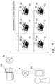
- the remote management apparatus 200 illustrated in Fig. 1 is an apparatus disposed at a remote location apart from a management-target building in order to effectively control a plurality of devices installed in the management-target building.
- registration work for registering each of the devices to the remote management apparatus 200 in a distinguished manner is required.
- the device-registration-work assisting system 100 illustrated in Fig. 2 and Fig. 3 is a system for assisting the worker with the registration work.
- the device-registration-work assisting system 100 allows the worker who performs the registration work to identify an indoor unit 12 installed at a location near the worker from among the plurality of indoor units 12 installed in the management-target building.
- the devices are the indoor units 12 of an air conditioner 10. Since the plurality of indoor units 12 all have the same configuration, Fig. 2 illustrates only one of them.
- the device-registration-work assisting system 100 mainly includes the air conditioner 10, electromagnetic wave emitters 20, and a mobile terminal 30.
- the air conditioner 10 is an apparatus capable of cooling and heating air in rooms or the like of the management-target building by performing a vapor compression refrigeration cycle.
- the air conditioner 10 is communicably connected to the remote management apparatus 200 via Internet N.
- the air conditioner 10 mainly includes an outdoor unit 11 serving as a heat source unit, the plurality of indoor units 12 serving as use units, and refrigerant connection pipes (not illustrated) that connect the outdoor unit 11 and the plurality of indoor units 12 to each other.
- the plurality of indoor units 12 are connected to the outdoor unit 11 in parallel with each other through the refrigerant connection pipes, so that a vapor compression refrigerant circuit of the air conditioner 10 is constituted.
- the refrigerant connection pipes are refrigerant pipes installed at the site when the air conditioner 10 is installed in the management-target building.
- the outdoor unit 11 is installed outdoors such as at a rooftop of the management-target building or at a place near a wall surface of the management-target building and constitutes part of the refrigerant circuit.
- the indoor units 12 are indoor units installed by being embedded in openings provided at the ceiling of rooms or the like of the management-target building.
- the plurality of indoor units 12 are disposed at the ceiling at predetermined intervals.
- Each of the indoor units 12 is connected to a power source, which is not illustrated, in a space above the ceiling and is thus supplied with power.
- Each of the plurality of indoor units 12 has identification information.
- the identification information is unique information, such as a device ID or a MAC address, given to each of the indoor units 12.
- the plurality of electromagnetic wave emitters 20 are provided to correspond to the respective indoor units 12 of the air conditioner 10.
- each of the electromagnetic wave emitters 20 is built in the corresponding indoor unit 12.
- the electromagnetic wave emitters 20 and the indoor units 12 are electrically connected to each other in a one-to-one manner.
- the plurality of electromagnetic wave emitters 20 are also disposed at the ceiling at predetermined intervals like the indoor units 12.
- the electromagnetic wave emitters 20 and the indoor units 12 are connected to each other through electric wires 23.
- Each of the electromagnetic wave emitters 20 is supplied with power from the air conditioner 10 through the electric wire 23. Since the plurality of electromagnetic wave emitters 20 all have the same configuration, description will be given below by using one of the plurality of electromagnetic wave emitters 20.
- the electromagnetic wave emitter 20 includes an emission unit 21 and a control unit 22.
- the emission unit 21 emits, using an electromagnetic wave 40, a signal containing identification information of the indoor unit 12 corresponding to each of the electromagnetic wave emitters 20.
- the electromagnetic wave 40 having the signal containing identification information is simply referred to as the electromagnetic wave 40.
- the electromagnetic wave 40 emitted by the emission unit 21 has a directivity such that the intensity of the electromagnetic wave 40 increases in a predetermined region.
- This predetermined region is a region where the mobile terminal 30 that performs measurement on the electromagnetic wave 40 is present.
- the intensity of the electromagnetic wave 40 increases in a direction of a floor where the worker carrying the mobile terminal 30 is present.
- the emission unit 21 is capable of emitting the plurality of electromagnetic waves 40 having different intensities.
- a first emission unit 21A that is the emission unit 21 corresponding to a first indoor unit 12A among the plurality of indoor units 12 emits a first electromagnetic wave 40a and a second electromagnetic wave 40b which are the electromagnetic waves 40 having different intensities.
- a second emission unit 21 B corresponding to a second indoor unit 12B emits a first electromagnetic wave 40c and a second electromagnetic wave 40d.
- a third emission unit 21C corresponding to a third indoor unit 12C emits a first electromagnetic wave 40e and a second electromagnetic wave 40f.
- the first electromagnetic waves 40a, 40c, and 40e respectively emitted by the first emission unit 21A, the second emission unit 21B, and the third emission unit 21C are the electromagnetic waves 40 having the same intensity.
- the second electromagnetic waves 40b, 40d, and 40f respectively emitted by the first emission unit 21A, the second emission unit 21B, and the third emission unit 21C are the electromagnetic waves 40 having the same intensity.
- the control unit 22 controls the electromagnetic waves 40 emitted by the emission unit 21.
- the control unit 22 controls the emission unit 21 to emit the electromagnetic waves 40 having different intensities at predetermined time intervals in series.
- the predetermined time intervals can be periodic time intervals or aperiodic time intervals.
- the control unit 22 controls the emission unit 21 to simultaneously emit the electromagnetic waves 40 having different intensities.
- the mobile terminal 30 illustrated in Fig. 3 is carried by the worker to the management-target building.
- the mobile terminal 30 is communicably connected to the remote management apparatus 200 via the Internet N.
- the mobile terminal 30 includes an intensity measurement unit 31, an information generation unit 32, a display control unit 33, a display unit 34, an input unit 35, and a selection unit 36.
- the intensity measurement unit 31 measures the intensity of the electromagnetic wave 40 emitted by the emission unit 21 of the electromagnetic wave emitter 20.
- the intensity measurement unit 31 is capable of simultaneously measuring the plurality of electromagnetic waves 40 emitted by the plurality of emission units 21.
- the intensity measurement unit 31 is capable of simultaneously measuring the first electromagnetic waves 40a, 40c, and 40e and the second electromagnetic waves 40b, 40d, and 40f emitted by the first emission unit 21A, the second emission unit 21B, and the third emission unit 21C, respectively.
- the information generation unit 32 On the basis of the electromagnetic waves 40 measured by the intensity measurement unit 31, the information generation unit 32 generates information in which identification information of the indoor unit 12 corresponding to each of the electromagnetic wave emitters 20 and the intensity of the electromagnetic waves 40 are associated with each other. For example, in Fig. 4 , the information generation unit 32 sums values of the intensities of the first electromagnetic wave 40a and the second electromagnetic wave 40b of the first emission unit 21Athat are measured by the intensity measurement unit 31, values of the intensities of the first electromagnetic wave 40c and the second electromagnetic wave 40d of the second emission unit 21B that are measured by the intensity measurement unit 31, and values of the intensities of the first electromagnetic wave 40e and the second electromagnetic wave 40f of the third emission unit 21C that are measured by the intensity measurement unit 31.
- the information generation unit 32 determines that the indoor unit 12 is installed at a location nearer the worker sequentially from the largest sum value, and generates information indicating that the second indoor unit 12B, the first indoor unit 12A, and the third indoor unit 12C are present at the nearer distance from the worker in this order. Note that the information generated by the information generation unit 32 is not limited to this. The generation method and the form of the information can be appropriately modified as long as the information allows the worker to identify the indoor unit 12 installed at a location near the worker.
- the display control unit 33 controls display of the display unit 34 on the basis of the information generated by the information generation unit 32.
- identification information of the first indoor unit 12A, identification information of the second indoor unit 12B, and identification information of the third indoor unit 12C in Fig. 4 are 12a, 12b, and 12c, respectively.
- the display control unit 33 causes the display unit 34 to display a list as illustrated in Fig. 5 , for example.
- pieces of information in which the pieces of identification information of the plurality of indoor units 12 are associated with intensities of the electromagnetic waves 40 are displayed in an order from the indoor unit 12 present at the nearest location from the worker.
- the display unit 34 displays the information, display of which is controlled by the display control unit 33.
- the input unit 35 is for inputting information for the registration work.
- the worker performs an input via an input screen displayed on the display unit 34 of the mobile terminal 30.
- the input screen is, for example, a screen illustrated in Fig. 6 . A method for inputting information for the registration work will be described later.
- the selection unit 36 is for selecting the indoor unit 12 to be subjected to the registration work from among the plurality of indoor units 12.
- the worker selects the indoor unit 12 to be subjected to the registration work via a selection screen displayed on the display unit 34 of the mobile terminal 30.
- the indoor unit 12 receives, via the Internet N and the remote management apparatus 200, information indicating that the indoor unit 12 is selected by the selection unit 36.
- the notification units 50 are for notifying the worker.
- the plurality of notification units 50 all have the same configuration.
- the notification units 50 are LEDs.
- the notification units 50 notify the worker by emitting light.
- the notification unit 50 receives a notification start instruction from the remote management apparatus 200 via the indoor unit 12.
- the notification unit 50 that has received the instruction emits light to notify the worker.
- the plurality of notification units 50 are provided to correspond to the respective indoor units 12 of the air conditioner 10.
- each of the notification units 50 is built in the corresponding indoor unit 12.
- the notification unit 50 may be disposed near the respective indoor units 12.
- the notification units 50 and the indoor units 12 are electrically connected to each other in a one-to-one manner.
- the plurality of notification units 50 are also disposed at the ceiling at predetermined intervals like the indoor units 12.
- Electric wires 51 that connect the notification units 50 and the indoor units 12 to each other include a communication line and a power source line.
- Each of the notification units 50 is supplied with power from the air conditioner 10 through the power source line of the electric wire 51 and is capable of communicating with the air conditioner 10 through the communication line of the electric wire 51.
- the remote management apparatus 200 illustrated in Fig. 7 is an apparatus disposed at a remote location apart from the management-target building in order to effectively control the plurality of indoor units 12 installed in the management-target building.
- the remote management apparatus 200 includes a control unit 201 and a storage unit 202.
- the remote management apparatus 200 is communicably connected to the air conditioner 10 and the mobile terminal 30 via the Internet N.
- the control unit 201 remotely controls the plurality of indoor units 12.
- the storage unit 202 includes a device information storage area 202a and an input information storage area 202b.
- the device information storage area 202a stores information regarding the plurality of indoor units 12.
- the information regarding the indoor unit 12 is information including identification information of the indoor unit 12 and location information that is information regarding the location where the indoor unit 12 is disposed in the management-target building.
- the input information storage area 202b is for storing information that is input with the input unit 35 of the mobile terminal 30 and that is received via the Internet N.
- the worker performs work for associating the identification information of each of the indoor units 12 stored in the remote management apparatus 200 with the location information.
- An example of an operation of the registration work relating to the remote management apparatus 200 and the device-registration-work assisting system 100 will be described below with reference to Fig. 8 . Note that the example of the operation illustrated in Fig. 8 can be appropriately modified. As long as the processing is appropriately performed, the order of any of steps may be switched, any of steps may be simultaneously performed, or another step not illustrated may be added.
- step S1 the remote management apparatus 200 transmits the information regarding the plurality of indoor units 12 stored in the device information storage area 152a thereof to the mobile terminal 30 via the Internet N.
- steps S2 to S6 the worker identifies the identification information of the indoor unit 12 installed at the location near the worker.
- step S2 the electromagnetic wave emitters 20 emit the electromagnetic waves 40.
- the electromagnetic waves 40 emitted by the emission units 21 are controlled by the respective control units 22.
- step S3 the intensity measurement unit 31 of the mobile terminal 30 measures the intensities of the plurality of electromagnetic waves 40 emitted by the emission units 21.
- the intensity measurement unit 31 continues the measurement for a certain period in which the information generation unit 32 generates information.
- step S4 on the basis of the electromagnetic waves 40 measured by the intensity measurement unit 31, the information generation unit 32 generates information in which the identification information of the indoor unit 12 corresponding to each of the electromagnetic wave emitters 20 and the intensity of the electromagnetic waves 40 are associated with each other.
- step S5 the display control unit 33 causes the display unit 34 to display the information generated by the information generation unit 32.
- the display unit 34 displays the information as illustrated in Fig. 5 .
- step S6 the worker identifies the identification information of the indoor unit 12 installed at the location near the worker on the basis of the information displayed on the display unit 34.
- steps S7 to S11 the worker performs the registration work to the remote management apparatus 200.
- step S7 the worker associates the identified identification information of the indoor unit 12 with the appropriate location information.
- the input screen that includes the information regarding the indoor units 12 received from the remote management apparatus 200 and that is illustrated in Fig. 6 is displayed on the input unit 35 of the mobile terminal 30.
- the worker performs an input of selecting the identified identification information of the indoor unit 12 from the list displayed in the input screen and associating the identification information with the location information. Consequently, the identification information of the indoor unit 12 and the location information are associated with each other.
- step S8 the associated information is transmitted from the mobile terminal 30 to the remote management apparatus 200 via the Internet N.
- step S9 the remote management apparatus 200 transmits, via the Internet N, a notification start instruction to the indoor unit 12 whose identification information is associated with the location information.
- the indoor unit 12 that has received the instruction transmits the instruction to the notification unit 50 through the electric wire 51.
- step S10 the notification unit 50 that has received the notification start instruction starts notification.
- the notification unit 50 notifies the worker by emitting light.
- step S11 the indoor unit 12 installed at the location near the worker notifies the worker, so that the worker confirms whether the identification information and the location information are appropriately associated with each other.
- step S12 the information in which the identification information and the location information are appropriately associated with each other is stored in the input information storage area 152b of the storage unit 202 of the remote management apparatus 200, and is used by the control unit 22 of the remote management apparatus 200 to effectively control the plurality of indoor units 12.
- the device-registration-work assisting system 100 includes: the notification unit 50 built in or disposed near each of the plurality of indoor units 12 subjected to registration work; and the mobile terminal 30 that is carried by a worker and that includes the display unit 34 configured to display information regarding each of the indoor units 12 and the selection unit 36 configured to select the indoor unit 12.
- the notification unit 50 notifies the worker by light in response to the corresponding indoor unit 12 being selected with the selection unit 36.
- the device-registration-work assisting system 100 further includes the electromagnetic wave emitter 20 built in or disposed near each of the plurality of indoor units 12 and configured to emit the electromagnetic wave 40.
- the mobile terminal 30 further includes the intensity measurement unit 31 configured to measure intensity of the electromagnetic wave 40 emitted by each of the electromagnetic wave emitters 20; and the display control unit 33 configured to control, on the basis of the intensity of the electromagnetic wave 40 measured by the intensity measurement unit 31, display of the display unit 34 such that the worker is able to identify the indoor unit 12 installed at the location near the worker.
- the indoor units 12 are installed by being embedded in openings provided at the ceiling of rooms or the like of the management-target building.
- the indoor units 12 are not necessary limited to this, and may be appropriately modified.
- the indoor units 12 may be ceiling-suspended units suspended from the ceiling or wall-mounted units mounted on the wall of the management-target building.
- the electromagnetic wave emitters 20 need not be built in the indoor units 12, and may be independently disposed near the indoor units 12 or may be built in other devices disposed near the indoor units 12.
- the notification units 50 need not be built in the indoor units 12, and may be independently disposed near the indoor units 12 or may be built in other devices disposed near the indoor units 12.
- the notification units 50 are LEDs and notify the worker by emitting light.
- the form of the notification units 50 is not limited to this.
- the notification units 50 may be buzzers or speakers and may notify the worker by emitting sound.
- the notification units 50 may notify the worker by motion.
- Fig. 9 is a cross-sectional view of the indoor unit 12.
- the indoor unit 12 includes a fan 12a serving as a first movable component, and a flap 12b serving as a second movable component.
- the fan 12a causes air to be blown out from the indoor unit 12 by rotary motion to notify the worker.
- the flap 12b changes a direction of the air blown out from the indoor unit 12 to notify the worker.
- Both the fan 12a and the flap 12b may be used as the notification unit 50, or the fan 12a alone may be used as the notification unit 50.
- the first movable component and the second movable component are not limited to the fan 12a and the flap 12b, respectively, and may be any components capable of notifying the worker by motion.
- the display unit 34 of the mobile terminal 30 displays the information generated by the information generation unit 32 in association with the identification information of the indoor unit 12 corresponding to the electromagnetic wave emitter 20 in a manner as illustrated in Fig. 5 .
- the display is not limited to this.
- the display unit 34 may display only the pieces of identification information of the plurality of indoor units 12 in ascending order, or may display only the indoor unit 12 installed at the location nearest the worker.
- the display unit 34 performs the display that allows the worker to identify the indoor unit 12 installed at a location near the worker.
- the worker associates the identified identification information of the indoor unit 12 with the location information.
- the worker may associate the location information with the identified identification information of the indoor unit 12.
- an input screen as illustrated in Fig. 10 is displayed on the input unit 35 of the mobile terminal 30. The worker selects appropriate location information from a layout diagram of the indoor units 12 in the management-target building displayed in the input screen, and inputs the identified identification information of the indoor unit 12. Consequently, the location information and the identification information of the indoor unit 12 are associated with each other.
- the information in which the identification information and the location information are associated with each other is input from the mobile terminal 30.
- the information may be input with each remote controller of the corresponding indoor unit 12.
- the remote controller is a so-called wired remote control device and is connected to the corresponding indoor unit 12 through a communication line.
- the information input from the remote controller is transmitted to the remote management apparatus 200 via the Internet N.
- an instruction to emit the electromagnetic wave 40 may be given by the remote control.
- the mobile terminal 30 is connected to the Internet N and is capable of communicating with the remote management apparatus 200.
- the mobile terminal 30 need not be connected to the Internet N.
- the mobile terminal 30 performs short-range wireless communication with the indoor unit 12 and transmits the information in which the identification information and the location information are associated with each other to the remote management apparatus 200 via the indoor unit 12.
- the worker may bring the mobile terminal 30 to a location where the remote management apparatus 200 is present after all the registration work is completed and may connect the mobile terminal 30 to the remote management apparatus 200 with a cable to transmit the information.
- the electromagnetic wave emitters 20 emit the electromagnetic waves 40 in step S2 of the example of the operation of the registration work.
- the electromagnetic wave emitters 20 may emit the electromagnetic waves 40 all the time.
- step S2 of the example of the operation of the registration work may be omitted.
- the notification unit 50 that has received the identification information by the worker and the notification start instruction starts notification in step S10 of the example of the operation of the registration work.
- the notification unit 50 performs notification after the identification information and the location information are associated with each other.
- a timing at which the notification unit 50 performs notification is not limited to this.
- the notification unit 50 may perform notification in response to the corresponding indoor unit 12 being selected with the mobile terminal 30 during the registration work performed by the worker.
Landscapes
- Engineering & Computer Science (AREA)
- Chemical & Material Sciences (AREA)
- Combustion & Propulsion (AREA)
- Mechanical Engineering (AREA)
- General Engineering & Computer Science (AREA)
- Computer Networks & Wireless Communication (AREA)
- Physics & Mathematics (AREA)
- General Physics & Mathematics (AREA)
- Human Computer Interaction (AREA)
- Air Conditioning Control Device (AREA)
- Selective Calling Equipment (AREA)
Abstract
Description
- The present disclosure relates to a device-registration-work assisting system.
- As described in PTL 1 (
Japanese Patent No. 6167971 - In the case where a plurality of devices are installed in a management-target building, the plurality of devices need to be registered to a remote management apparatus in a distinguished manner in order to effectively control the plurality of devices.
- A device-registration-work assisting system according to a first aspect includes a notification unit and a mobile terminal. The notification unit is built in or disposed near each of a plurality of devices subjected to registration work. The mobile terminal is carried by a worker. The mobile terminal includes a display unit and a selection unit. The display unit displays information regarding each of the devices. The selection unit selects the device. The notification unit notifies the worker by light, sound, or motion in response to the corresponding device being selected with the selection unit.
- This allows the worker to efficiently perform work for registering a plurality of devices to a remote management apparatus in a distinguished manner.
- A device-registration-work assisting system according to a second aspect is the system according to the first aspect, in which the notification unit emits at least one of light or sound.
- A device-registration-work assisting system according to a third aspect is the system according to the first aspect, in which the devices are air-conditioning indoor units. The notification unit is a first movable component configured to move to blow out air from the air-conditioning indoor unit or a second movable component configured to move to change a direction of the air blown out from the air-conditioning indoor unit.
- A device-registration-work assisting system according to a fourth aspect is the system according to any of the first aspect to the third aspect, further including an electromagnetic wave emitter built in or disposed near each of the plurality of devices and configured to emit an electromagnetic wave. The mobile terminal further includes an intensity measurement unit and a display control unit. The intensity measurement unit measures an intensity of the electromagnetic wave emitted by each of the electromagnetic wave emitters. The display control unit controls, on the basis of the intensity of the electromagnetic wave measured by the intensity measurement unit, display of the display unit such that the worker is able to identify the device installed at a location near the worker.
-
-
Fig. 1 is a diagram illustrating an overall configuration of a device-registration-work assisting system and a management apparatus. -
Fig. 2 is a schematic configuration diagram of an air conditioner and an electromagnetic wave emitter. -
Fig. 3 is a schematic configuration diagram of a mobile terminal. -
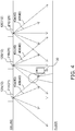
Fig. 4 illustrates an example of a screen presenting intensities of electromagnetic waves. -
Fig. 5 is a schematic configuration diagram of the remote management apparatus. -
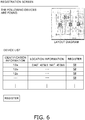
Fig. 6 illustrates an example of an input screen for registration work. -
Fig. 7 is a schematic configuration diagram of the remote management apparatus. -
Fig. 8 is a flowchart of an operation of registration work. -
Fig. 9 is a cross-sectional view of an indoor unit. -
Fig. 10 illustrates an example of an input screen for registration work according to a modification. - A device-registration-
work assisting system 100 and aremote management apparatus 200 according to an embodiment of the present disclosure will be described below. Note that the embodiment below presents a specific example and does not limit the technical scope, and thus may be appropriately modified within a scope not departing from the gist. - The
remote management apparatus 200 illustrated inFig. 1 is an apparatus disposed at a remote location apart from a management-target building in order to effectively control a plurality of devices installed in the management-target building. In order for theremote management apparatus 200 to control the plurality of devices, registration work for registering each of the devices to theremote management apparatus 200 in a distinguished manner is required. A worker visits the management-target building and performs this registration work. The device-registration-work assisting system 100 illustrated inFig. 2 andFig. 3 is a system for assisting the worker with the registration work. The device-registration-work assisting system 100 allows the worker who performs the registration work to identify anindoor unit 12 installed at a location near the worker from among the plurality ofindoor units 12 installed in the management-target building. - In the present embodiment, the devices are the
indoor units 12 of anair conditioner 10. Since the plurality ofindoor units 12 all have the same configuration,Fig. 2 illustrates only one of them. The device-registration-work assisting system 100 mainly includes theair conditioner 10,electromagnetic wave emitters 20, and amobile terminal 30. - The
air conditioner 10 is an apparatus capable of cooling and heating air in rooms or the like of the management-target building by performing a vapor compression refrigeration cycle. Theair conditioner 10 is communicably connected to theremote management apparatus 200 via Internet N. - The
air conditioner 10 mainly includes anoutdoor unit 11 serving as a heat source unit, the plurality ofindoor units 12 serving as use units, and refrigerant connection pipes (not illustrated) that connect theoutdoor unit 11 and the plurality ofindoor units 12 to each other. The plurality ofindoor units 12 are connected to theoutdoor unit 11 in parallel with each other through the refrigerant connection pipes, so that a vapor compression refrigerant circuit of theair conditioner 10 is constituted. The refrigerant connection pipes are refrigerant pipes installed at the site when theair conditioner 10 is installed in the management-target building. - The
outdoor unit 11 is installed outdoors such as at a rooftop of the management-target building or at a place near a wall surface of the management-target building and constitutes part of the refrigerant circuit. - In the present embodiment, the
indoor units 12 are indoor units installed by being embedded in openings provided at the ceiling of rooms or the like of the management-target building. The plurality ofindoor units 12 are disposed at the ceiling at predetermined intervals. Each of theindoor units 12 is connected to a power source, which is not illustrated, in a space above the ceiling and is thus supplied with power. Each of the plurality ofindoor units 12 has identification information. The identification information is unique information, such as a device ID or a MAC address, given to each of theindoor units 12. - The plurality of
electromagnetic wave emitters 20 are provided to correspond to the respectiveindoor units 12 of theair conditioner 10. In the present embodiment, each of theelectromagnetic wave emitters 20 is built in the correspondingindoor unit 12. The electromagnetic wave emitters 20 and theindoor units 12 are electrically connected to each other in a one-to-one manner. Thus, the plurality ofelectromagnetic wave emitters 20 are also disposed at the ceiling at predetermined intervals like theindoor units 12. - The electromagnetic wave emitters 20 and the
indoor units 12 are connected to each other throughelectric wires 23. Each of theelectromagnetic wave emitters 20 is supplied with power from theair conditioner 10 through theelectric wire 23. Since the plurality ofelectromagnetic wave emitters 20 all have the same configuration, description will be given below by using one of the plurality ofelectromagnetic wave emitters 20. - The
electromagnetic wave emitter 20 includes anemission unit 21 and acontrol unit 22. - The
emission unit 21 emits, using anelectromagnetic wave 40, a signal containing identification information of theindoor unit 12 corresponding to each of theelectromagnetic wave emitters 20. Hereinafter, theelectromagnetic wave 40 having the signal containing identification information is simply referred to as theelectromagnetic wave 40. - The
electromagnetic wave 40 emitted by theemission unit 21 has a directivity such that the intensity of theelectromagnetic wave 40 increases in a predetermined region. This predetermined region is a region where themobile terminal 30 that performs measurement on theelectromagnetic wave 40 is present. For example, as illustrated inFig. 4 , the intensity of theelectromagnetic wave 40 increases in a direction of a floor where the worker carrying themobile terminal 30 is present. - The
emission unit 21 is capable of emitting the plurality ofelectromagnetic waves 40 having different intensities. For example, inFig. 4 , afirst emission unit 21A that is theemission unit 21 corresponding to a firstindoor unit 12A among the plurality ofindoor units 12 emits a firstelectromagnetic wave 40a and a secondelectromagnetic wave 40b which are theelectromagnetic waves 40 having different intensities. Likewise, asecond emission unit 21 B corresponding to a secondindoor unit 12B emits a firstelectromagnetic wave 40c and a secondelectromagnetic wave 40d. Athird emission unit 21C corresponding to a thirdindoor unit 12C emits a firstelectromagnetic wave 40e and a secondelectromagnetic wave 40f. The firstelectromagnetic waves first emission unit 21A, thesecond emission unit 21B, and thethird emission unit 21C are theelectromagnetic waves 40 having the same intensity. The secondelectromagnetic waves first emission unit 21A, thesecond emission unit 21B, and thethird emission unit 21C are theelectromagnetic waves 40 having the same intensity. - The
control unit 22 controls theelectromagnetic waves 40 emitted by theemission unit 21. For example, thecontrol unit 22 controls theemission unit 21 to emit theelectromagnetic waves 40 having different intensities at predetermined time intervals in series. The predetermined time intervals can be periodic time intervals or aperiodic time intervals. Alternatively, for example, thecontrol unit 22 controls theemission unit 21 to simultaneously emit theelectromagnetic waves 40 having different intensities. - The
mobile terminal 30 illustrated inFig. 3 is carried by the worker to the management-target building. Themobile terminal 30 is communicably connected to theremote management apparatus 200 via the Internet N. - The
mobile terminal 30 includes anintensity measurement unit 31, aninformation generation unit 32, adisplay control unit 33, adisplay unit 34, aninput unit 35, and aselection unit 36. - The
intensity measurement unit 31 measures the intensity of theelectromagnetic wave 40 emitted by theemission unit 21 of theelectromagnetic wave emitter 20. Theintensity measurement unit 31 is capable of simultaneously measuring the plurality ofelectromagnetic waves 40 emitted by the plurality ofemission units 21. For example, inFig. 4 , theintensity measurement unit 31 is capable of simultaneously measuring the firstelectromagnetic waves electromagnetic waves first emission unit 21A, thesecond emission unit 21B, and thethird emission unit 21C, respectively. - On the basis of the
electromagnetic waves 40 measured by theintensity measurement unit 31, theinformation generation unit 32 generates information in which identification information of theindoor unit 12 corresponding to each of theelectromagnetic wave emitters 20 and the intensity of theelectromagnetic waves 40 are associated with each other. For example, inFig. 4 , theinformation generation unit 32 sums values of the intensities of the firstelectromagnetic wave 40a and the secondelectromagnetic wave 40b of the first emission unit 21Athat are measured by theintensity measurement unit 31, values of the intensities of the firstelectromagnetic wave 40c and the secondelectromagnetic wave 40d of thesecond emission unit 21B that are measured by theintensity measurement unit 31, and values of the intensities of the firstelectromagnetic wave 40e and the secondelectromagnetic wave 40f of thethird emission unit 21C that are measured by theintensity measurement unit 31. Theinformation generation unit 32 determines that theindoor unit 12 is installed at a location nearer the worker sequentially from the largest sum value, and generates information indicating that the secondindoor unit 12B, the firstindoor unit 12A, and the thirdindoor unit 12C are present at the nearer distance from the worker in this order. Note that the information generated by theinformation generation unit 32 is not limited to this. The generation method and the form of the information can be appropriately modified as long as the information allows the worker to identify theindoor unit 12 installed at a location near the worker. - The
display control unit 33 controls display of thedisplay unit 34 on the basis of the information generated by theinformation generation unit 32. Suppose that identification information of the firstindoor unit 12A, identification information of the secondindoor unit 12B, and identification information of the thirdindoor unit 12C inFig. 4 are 12a, 12b, and 12c, respectively. Then, thedisplay control unit 33 causes thedisplay unit 34 to display a list as illustrated inFig. 5 , for example. InFig. 5 , on the basis of the information generated by theinformation generation unit 32, pieces of information in which the pieces of identification information of the plurality ofindoor units 12 are associated with intensities of theelectromagnetic waves 40 are displayed in an order from theindoor unit 12 present at the nearest location from the worker. - The
display unit 34 displays the information, display of which is controlled by thedisplay control unit 33. - The
input unit 35 is for inputting information for the registration work. The worker performs an input via an input screen displayed on thedisplay unit 34 of themobile terminal 30. The input screen is, for example, a screen illustrated inFig. 6 . A method for inputting information for the registration work will be described later. - The
selection unit 36 is for selecting theindoor unit 12 to be subjected to the registration work from among the plurality ofindoor units 12. The worker selects theindoor unit 12 to be subjected to the registration work via a selection screen displayed on thedisplay unit 34 of themobile terminal 30. Theindoor unit 12 receives, via the Internet N and theremote management apparatus 200, information indicating that theindoor unit 12 is selected by theselection unit 36. - The
notification units 50 are for notifying the worker. The plurality ofnotification units 50 all have the same configuration. In the present embodiment, thenotification units 50 are LEDs. Thenotification units 50 notify the worker by emitting light. In response to completion of the registration work for theindoor unit 12 selected with theselection unit 36, thenotification unit 50 receives a notification start instruction from theremote management apparatus 200 via theindoor unit 12. Thenotification unit 50 that has received the instruction emits light to notify the worker. - The plurality of
notification units 50 are provided to correspond to the respectiveindoor units 12 of theair conditioner 10. In the present embodiment, each of thenotification units 50 is built in the correspondingindoor unit 12. However, thenotification unit 50 may be disposed near the respectiveindoor units 12. Thenotification units 50 and theindoor units 12 are electrically connected to each other in a one-to-one manner. Thus, the plurality ofnotification units 50 are also disposed at the ceiling at predetermined intervals like theindoor units 12. Electric wires 51 that connect thenotification units 50 and theindoor units 12 to each other include a communication line and a power source line. Each of thenotification units 50 is supplied with power from theair conditioner 10 through the power source line of the electric wire 51 and is capable of communicating with theair conditioner 10 through the communication line of the electric wire 51. - The
remote management apparatus 200 illustrated inFig. 7 is an apparatus disposed at a remote location apart from the management-target building in order to effectively control the plurality ofindoor units 12 installed in the management-target building. Theremote management apparatus 200 includes acontrol unit 201 and astorage unit 202. Theremote management apparatus 200 is communicably connected to theair conditioner 10 and themobile terminal 30 via the Internet N. - The
control unit 201 remotely controls the plurality ofindoor units 12. - The
storage unit 202 includes a deviceinformation storage area 202a and an inputinformation storage area 202b. The deviceinformation storage area 202a stores information regarding the plurality ofindoor units 12. The information regarding theindoor unit 12 is information including identification information of theindoor unit 12 and location information that is information regarding the location where theindoor unit 12 is disposed in the management-target building. The inputinformation storage area 202b is for storing information that is input with theinput unit 35 of themobile terminal 30 and that is received via the Internet N. - In the registration work, the worker performs work for associating the identification information of each of the
indoor units 12 stored in theremote management apparatus 200 with the location information. An example of an operation of the registration work relating to theremote management apparatus 200 and the device-registration-work assisting system 100 will be described below with reference toFig. 8 . Note that the example of the operation illustrated inFig. 8 can be appropriately modified. As long as the processing is appropriately performed, the order of any of steps may be switched, any of steps may be simultaneously performed, or another step not illustrated may be added. - First, in step S1, the
remote management apparatus 200 transmits the information regarding the plurality ofindoor units 12 stored in the device information storage area 152a thereof to themobile terminal 30 via the Internet N. - Subsequently, in steps S2 to S6, the worker identifies the identification information of the
indoor unit 12 installed at the location near the worker. - In step S2, the
electromagnetic wave emitters 20 emit theelectromagnetic waves 40. Theelectromagnetic waves 40 emitted by theemission units 21 are controlled by therespective control units 22. - In step S3, the
intensity measurement unit 31 of the mobile terminal 30 measures the intensities of the plurality ofelectromagnetic waves 40 emitted by theemission units 21. Theintensity measurement unit 31 continues the measurement for a certain period in which theinformation generation unit 32 generates information. - In step S4, on the basis of the
electromagnetic waves 40 measured by theintensity measurement unit 31, theinformation generation unit 32 generates information in which the identification information of theindoor unit 12 corresponding to each of theelectromagnetic wave emitters 20 and the intensity of theelectromagnetic waves 40 are associated with each other. - In step S5, the
display control unit 33 causes thedisplay unit 34 to display the information generated by theinformation generation unit 32. For example, thedisplay unit 34 displays the information as illustrated inFig. 5 . - In step S6, the worker identifies the identification information of the
indoor unit 12 installed at the location near the worker on the basis of the information displayed on thedisplay unit 34. - Subsequently, in steps S7 to S11, the worker performs the registration work to the
remote management apparatus 200. - In step S7, the worker associates the identified identification information of the
indoor unit 12 with the appropriate location information. Specifically, the input screen that includes the information regarding theindoor units 12 received from theremote management apparatus 200 and that is illustrated inFig. 6 is displayed on theinput unit 35 of themobile terminal 30. The worker performs an input of selecting the identified identification information of theindoor unit 12 from the list displayed in the input screen and associating the identification information with the location information. Consequently, the identification information of theindoor unit 12 and the location information are associated with each other. - In step S8, the associated information is transmitted from the
mobile terminal 30 to theremote management apparatus 200 via the Internet N. - In step S9, the
remote management apparatus 200 transmits, via the Internet N, a notification start instruction to theindoor unit 12 whose identification information is associated with the location information. Theindoor unit 12 that has received the instruction transmits the instruction to thenotification unit 50 through the electric wire 51. - In step S10, the
notification unit 50 that has received the notification start instruction starts notification. Herein, thenotification unit 50 notifies the worker by emitting light. - In step S11, the
indoor unit 12 installed at the location near the worker notifies the worker, so that the worker confirms whether the identification information and the location information are appropriately associated with each other. - In step S12, the information in which the identification information and the location information are appropriately associated with each other is stored in the input information storage area 152b of the
storage unit 202 of theremote management apparatus 200, and is used by thecontrol unit 22 of theremote management apparatus 200 to effectively control the plurality ofindoor units 12. - The device-registration-
work assisting system 100 includes: thenotification unit 50 built in or disposed near each of the plurality ofindoor units 12 subjected to registration work; and themobile terminal 30 that is carried by a worker and that includes thedisplay unit 34 configured to display information regarding each of theindoor units 12 and theselection unit 36 configured to select theindoor unit 12. Thenotification unit 50 notifies the worker by light in response to the correspondingindoor unit 12 being selected with theselection unit 36. - This allows the worker to confirm whether the plurality of
indoor units 12 are appropriately registered to theremote management apparatus 200 and to efficiently perform the registration work. - The device-registration-
work assisting system 100 further includes theelectromagnetic wave emitter 20 built in or disposed near each of the plurality ofindoor units 12 and configured to emit theelectromagnetic wave 40. Themobile terminal 30 further includes theintensity measurement unit 31 configured to measure intensity of theelectromagnetic wave 40 emitted by each of theelectromagnetic wave emitters 20; and thedisplay control unit 33 configured to control, on the basis of the intensity of theelectromagnetic wave 40 measured by theintensity measurement unit 31, display of thedisplay unit 34 such that the worker is able to identify theindoor unit 12 installed at the location near the worker. - This allows the worker to identify the
indoor unit 12 installed at a location near the worker in accordance with the information displayed on thedisplay unit 34 of themobile terminal 30 and to efficiently perform the registration work. - The embodiment described above can be appropriately modified as presented by modifications below. Note that each of the modifications may be used in combination with another modification within a range not causing any contradiction.
- In the embodiment described above, the
indoor units 12 are installed by being embedded in openings provided at the ceiling of rooms or the like of the management-target building. However, theindoor units 12 are not necessary limited to this, and may be appropriately modified. For example, theindoor units 12 may be ceiling-suspended units suspended from the ceiling or wall-mounted units mounted on the wall of the management-target building. - In addition, the
electromagnetic wave emitters 20 need not be built in theindoor units 12, and may be independently disposed near theindoor units 12 or may be built in other devices disposed near theindoor units 12. - Further, the
notification units 50 need not be built in theindoor units 12, and may be independently disposed near theindoor units 12 or may be built in other devices disposed near theindoor units 12. - In the embodiment described above, the
notification units 50 are LEDs and notify the worker by emitting light. However, the form of thenotification units 50 is not limited to this. For example, thenotification units 50 may be buzzers or speakers and may notify the worker by emitting sound. - The
notification units 50 may notify the worker by motion.Fig. 9 is a cross-sectional view of theindoor unit 12. Theindoor unit 12 includes afan 12a serving as a first movable component, and aflap 12b serving as a second movable component. Thefan 12a causes air to be blown out from theindoor unit 12 by rotary motion to notify the worker. Theflap 12b changes a direction of the air blown out from theindoor unit 12 to notify the worker. Both thefan 12a and theflap 12b may be used as thenotification unit 50, or thefan 12a alone may be used as thenotification unit 50. Note that the first movable component and the second movable component are not limited to thefan 12a and theflap 12b, respectively, and may be any components capable of notifying the worker by motion. - In the embodiment described above, in accordance with control performed by the
display control unit 33, thedisplay unit 34 of themobile terminal 30 displays the information generated by theinformation generation unit 32 in association with the identification information of theindoor unit 12 corresponding to theelectromagnetic wave emitter 20 in a manner as illustrated inFig. 5 . However, the display is not limited to this. - For example, on the basis of the information generated by the
information generation unit 32, thedisplay unit 34 may display only the pieces of identification information of the plurality ofindoor units 12 in ascending order, or may display only theindoor unit 12 installed at the location nearest the worker. Thedisplay unit 34 performs the display that allows the worker to identify theindoor unit 12 installed at a location near the worker. - In the embodiment described above, in the registration work, the worker associates the identified identification information of the
indoor unit 12 with the location information. However, the worker may associate the location information with the identified identification information of theindoor unit 12. Specifically, an input screen as illustrated inFig. 10 is displayed on theinput unit 35 of themobile terminal 30. The worker selects appropriate location information from a layout diagram of theindoor units 12 in the management-target building displayed in the input screen, and inputs the identified identification information of theindoor unit 12. Consequently, the location information and the identification information of theindoor unit 12 are associated with each other. - In the embodiment described above, in the registration work, information in which the identification information and the location information are associated with each other is input from the
mobile terminal 30. However, the information may be input with each remote controller of the correspondingindoor unit 12. The remote controller is a so-called wired remote control device and is connected to the correspondingindoor unit 12 through a communication line. The information input from the remote controller is transmitted to theremote management apparatus 200 via the Internet N. - In addition, an instruction to emit the
electromagnetic wave 40 may be given by the remote control. - In the embodiment described above, the
mobile terminal 30 is connected to the Internet N and is capable of communicating with theremote management apparatus 200. However, themobile terminal 30 need not be connected to the Internet N. In this case, themobile terminal 30 performs short-range wireless communication with theindoor unit 12 and transmits the information in which the identification information and the location information are associated with each other to theremote management apparatus 200 via theindoor unit 12. - Alternatively, the worker may bring the
mobile terminal 30 to a location where theremote management apparatus 200 is present after all the registration work is completed and may connect themobile terminal 30 to theremote management apparatus 200 with a cable to transmit the information. - In the embodiment described above, the
electromagnetic wave emitters 20 emit theelectromagnetic waves 40 in step S2 of the example of the operation of the registration work. However, theelectromagnetic wave emitters 20 may emit theelectromagnetic waves 40 all the time. Thus, step S2 of the example of the operation of the registration work may be omitted. - In the embodiment described above, the
notification unit 50 that has received the identification information by the worker and the notification start instruction starts notification in step S10 of the example of the operation of the registration work. However, thenotification unit 50 performs notification after the identification information and the location information are associated with each other. However, a timing at which thenotification unit 50 performs notification is not limited to this. For example, thenotification unit 50 may perform notification in response to the correspondingindoor unit 12 being selected with themobile terminal 30 during the registration work performed by the worker. - While the embodiment of the present disclosure has been described above, it should be understood that various modifications can be made on the configurations and details without departing from the gist and the scope of the present disclosure that are described in the claims.
-
- 12
- device
- 12a
- first movable component
- 12b
- second movable component
- 20
- electromagnetic wave emitter
- 30
- mobile terminal
- 31
- intensity measurement unit
- 33
- display control unit
- 34
- display unit
- 36
- selection unit
- 40
- electromagnetic wave
- 50
- notification unit
- PTL 1:
Japanese Patent No. 6167971
Claims (4)
- A device-registration-work assisting system comprising:a notification unit (50) built in or disposed near each of a plurality of devices (12) subjected to registration work; anda mobile terminal (30) carried by a worker, the mobile terminal including a display unit (34) configured to display information regarding each of the devices (12), and a selection unit (36) configured to select the device (12),wherein the notification unit (50) notifies the worker by light, sound, or motion in response to the corresponding device (12) being selected with the selection unit (36).
- The device-registration-work assisting system according to Claim 1,
wherein the notification unit (50) is configured to emit at least one of light or sound. - The device-registration-work assisting system according to Claim 1,wherein the devices (12) are air-conditioning indoor units, andthe notification unit (50) is a first movable component (12a) configured to move to blow out air from the air-conditioning indoor unit or a second movable component (12b) configured to move to change a direction of the air blown out from the air-conditioning indoor unit (12).
- The device-registration-work assisting system according to any of Claims 1 to 3, further comprising:an electromagnetic wave emitter (20) built in or disposed near each of the plurality of devices (12) and configured to emit an electromagnetic wave (40),wherein the mobile terminal (30) further includesan intensity measurement unit (31) configured to measure an intensity of the electromagnetic wave (40) emitted by the electromagnetic wave emitter (20), anda display control unit (33) configured to control, on the basis of the intensity of the electromagnetic wave (40) measured by the intensity measurement unit (31), display of the display unit (34) such that the worker is able to identify the device (12) installed at a location near the worker.
Applications Claiming Priority (2)
| Application Number | Priority Date | Filing Date | Title |
|---|---|---|---|
| JP2019023528A JP6919665B2 (en) | 2019-02-13 | 2019-02-13 | Device registration work support system |
| PCT/JP2020/004540 WO2020166481A1 (en) | 2019-02-13 | 2020-02-06 | Apparatus registration work assistance system |
Publications (3)
| Publication Number | Publication Date |
|---|---|
| EP3926969A1 true EP3926969A1 (en) | 2021-12-22 |
| EP3926969A4 EP3926969A4 (en) | 2022-03-23 |
| EP3926969B1 EP3926969B1 (en) | 2023-07-05 |
Family
ID=72045423
Family Applications (1)
| Application Number | Title | Priority Date | Filing Date |
|---|---|---|---|
| EP20754876.9A Active EP3926969B1 (en) | 2019-02-13 | 2020-02-06 | Apparatus registration work assistance system |
Country Status (6)
| Country | Link |
|---|---|
| US (1) | US11879652B2 (en) |
| EP (1) | EP3926969B1 (en) |
| JP (1) | JP6919665B2 (en) |
| CN (1) | CN113412628B (en) |
| AU (1) | AU2020220701B2 (en) |
| WO (1) | WO2020166481A1 (en) |
Cited By (1)
| Publication number | Priority date | Publication date | Assignee | Title |
|---|---|---|---|---|
| EP4502899A4 (en) * | 2022-03-30 | 2025-09-03 | Daikin Ind Ltd | WORK ASSISTANCE SYSTEM FOR REGISTRATION OF A DEVICE |
Family Cites Families (10)
| Publication number | Priority date | Publication date | Assignee | Title |
|---|---|---|---|---|
| JP5103167B2 (en) * | 2007-12-28 | 2012-12-19 | アズビル株式会社 | Management address setting method and system for wireless device |
| JP2010009558A (en) * | 2008-05-28 | 2010-01-14 | Oki Semiconductor Co Ltd | Image recognition device, electrical device operation control unit, electric appliance, image recognition program, and semiconductor device |
| KR20120093810A (en) * | 2009-06-23 | 2012-08-23 | 코닌클리즈케 필립스 일렉트로닉스 엔.브이. | Pushbits for semi-synchronized pointing |
| US9256230B2 (en) * | 2010-11-19 | 2016-02-09 | Google Inc. | HVAC schedule establishment in an intelligent, network-connected thermostat |
| JP5404860B2 (en) | 2012-07-10 | 2014-02-05 | 株式会社東芝 | Information processing terminal and information processing method |
| JP2015050752A (en) * | 2013-09-04 | 2015-03-16 | シャープ株式会社 | Registration support system for remote control system |
| WO2015104248A1 (en) * | 2014-01-10 | 2015-07-16 | Koninklijke Philips N.V. | Tablet-based commissioning tool for addressable lighting |
| JP6167971B2 (en) | 2014-03-31 | 2017-07-26 | ダイキン工業株式会社 | Remote management system |
| WO2017223008A1 (en) * | 2016-06-21 | 2017-12-28 | Osram Sylvania Inc. | Wireless beacon-enabled luminaire identification system and method for determining the position of a portable device |
| JP6636176B2 (en) * | 2016-12-05 | 2020-01-29 | 三菱電機株式会社 | Remote controller and air conditioning system |
-
2019
- 2019-02-13 JP JP2019023528A patent/JP6919665B2/en active Active
-
2020
- 2020-02-06 CN CN202080013157.1A patent/CN113412628B/en active Active
- 2020-02-06 US US17/426,570 patent/US11879652B2/en active Active
- 2020-02-06 EP EP20754876.9A patent/EP3926969B1/en active Active
- 2020-02-06 AU AU2020220701A patent/AU2020220701B2/en active Active
- 2020-02-06 WO PCT/JP2020/004540 patent/WO2020166481A1/en not_active Ceased
Cited By (1)
| Publication number | Priority date | Publication date | Assignee | Title |
|---|---|---|---|---|
| EP4502899A4 (en) * | 2022-03-30 | 2025-09-03 | Daikin Ind Ltd | WORK ASSISTANCE SYSTEM FOR REGISTRATION OF A DEVICE |
Also Published As
| Publication number | Publication date |
|---|---|
| US20220107110A1 (en) | 2022-04-07 |
| AU2020220701B2 (en) | 2022-11-17 |
| EP3926969A4 (en) | 2022-03-23 |
| WO2020166481A1 (en) | 2020-08-20 |
| JP2020136726A (en) | 2020-08-31 |
| CN113412628B (en) | 2024-07-23 |
| US11879652B2 (en) | 2024-01-23 |
| AU2020220701A1 (en) | 2021-10-07 |
| CN113412628A (en) | 2021-09-17 |
| EP3926969B1 (en) | 2023-07-05 |
| JP6919665B2 (en) | 2021-08-18 |
Similar Documents
| Publication | Publication Date | Title |
|---|---|---|
| JP2015097211A (en) | Lighting control method and system | |
| US11629875B2 (en) | Operating system, information processing device, control system, and infrared output device | |
| CN110140015B (en) | Central control device, indoor device and remote control device of air conditioning equipment | |
| CN101257753A (en) | Lighting control system and position detection method used in the lighting control system | |
| EP3926969B1 (en) | Apparatus registration work assistance system | |
| JP6636176B2 (en) | Remote controller and air conditioning system | |
| US20230280884A1 (en) | Information processing method | |
| US11334043B2 (en) | Operating terminal and facility device control system | |
| JP2020136725A (en) | Mobile terminal and apparatus registration work support system | |
| KR101302255B1 (en) | Remote supervision (measurement) control method using smartphone and software device thereof | |
| WO2020066017A1 (en) | Air conditioning system and application program | |
| JP7558417B2 (en) | Installation location identification system and installation location identification method | |
| US20260082315A1 (en) | Information terminal, communication system, display method, and recording medium | |
| JP2021072228A (en) | Communication failure estimation system for lighting | |
| JPWO2018179107A1 (en) | Identification information confirmation system, air conditioner, identification information confirmation method, and program | |
| JP2023064263A (en) | Electrical installations, electrical installation systems and programs | |
| JP2021156454A (en) | Air conditioner maintenance support system and maintenance terminal | |
| JP2023087554A (en) | equipment | |
| JP2026076660A (en) | Communication system | |
| JP2026079105A (en) | Information terminal, communication system, network registration method, and program | |
| JP2012021661A (en) | System for detecting existence location |
Legal Events
| Date | Code | Title | Description |
|---|---|---|---|
| STAA | Information on the status of an ep patent application or granted ep patent |
Free format text: STATUS: THE INTERNATIONAL PUBLICATION HAS BEEN MADE |
|
| PUAI | Public reference made under article 153(3) epc to a published international application that has entered the european phase |
Free format text: ORIGINAL CODE: 0009012 |
|
| STAA | Information on the status of an ep patent application or granted ep patent |
Free format text: STATUS: REQUEST FOR EXAMINATION WAS MADE |
|
| 17P | Request for examination filed |
Effective date: 20210827 |
|
| AK | Designated contracting states |
Kind code of ref document: A1 Designated state(s): AL AT BE BG CH CY CZ DE DK EE ES FI FR GB GR HR HU IE IS IT LI LT LU LV MC MK MT NL NO PL PT RO RS SE SI SK SM TR |
|
| A4 | Supplementary search report drawn up and despatched |
Effective date: 20220221 |
|
| RIC1 | Information provided on ipc code assigned before grant |
Ipc: G08C 17/00 20060101ALI20220215BHEP Ipc: F24F 11/52 20180101ALI20220215BHEP Ipc: H04Q 9/00 20060101AFI20220215BHEP |
|
| DAV | Request for validation of the european patent (deleted) | ||
| DAX | Request for extension of the european patent (deleted) | ||
| RAP3 | Party data changed (applicant data changed or rights of an application transferred) |
Owner name: DAIKIN INDUSTRIES, LTD. |
|
| GRAP | Despatch of communication of intention to grant a patent |
Free format text: ORIGINAL CODE: EPIDOSNIGR1 |
|
| STAA | Information on the status of an ep patent application or granted ep patent |
Free format text: STATUS: GRANT OF PATENT IS INTENDED |
|
| INTG | Intention to grant announced |
Effective date: 20230207 |
|
| GRAS | Grant fee paid |
Free format text: ORIGINAL CODE: EPIDOSNIGR3 |
|
| GRAA | (expected) grant |
Free format text: ORIGINAL CODE: 0009210 |
|
| STAA | Information on the status of an ep patent application or granted ep patent |
Free format text: STATUS: THE PATENT HAS BEEN GRANTED |
|
| AK | Designated contracting states |
Kind code of ref document: B1 Designated state(s): AL AT BE BG CH CY CZ DE DK EE ES FI FR GB GR HR HU IE IS IT LI LT LU LV MC MK MT NL NO PL PT RO RS SE SI SK SM TR |
|
| P01 | Opt-out of the competence of the unified patent court (upc) registered |
Effective date: 20230525 |
|
| REG | Reference to a national code |
Ref country code: CH Ref legal event code: EP |
|
| REG | Reference to a national code |
Ref country code: AT Ref legal event code: REF Ref document number: 1585910 Country of ref document: AT Kind code of ref document: T Effective date: 20230715 |
|
| REG | Reference to a national code |
Ref country code: DE Ref legal event code: R096 Ref document number: 602020013396 Country of ref document: DE |
|
| REG | Reference to a national code |
Ref country code: IE Ref legal event code: FG4D |
|
| REG | Reference to a national code |
Ref country code: LT Ref legal event code: MG9D |
|
| REG | Reference to a national code |
Ref country code: NL Ref legal event code: MP Effective date: 20230705 |
|
| REG | Reference to a national code |
Ref country code: AT Ref legal event code: MK05 Ref document number: 1585910 Country of ref document: AT Kind code of ref document: T Effective date: 20230705 |
|
| PG25 | Lapsed in a contracting state [announced via postgrant information from national office to epo] |
Ref country code: NL Free format text: LAPSE BECAUSE OF FAILURE TO SUBMIT A TRANSLATION OF THE DESCRIPTION OR TO PAY THE FEE WITHIN THE PRESCRIBED TIME-LIMIT Effective date: 20230705 |
|
| PG25 | Lapsed in a contracting state [announced via postgrant information from national office to epo] |
Ref country code: GR Free format text: LAPSE BECAUSE OF FAILURE TO SUBMIT A TRANSLATION OF THE DESCRIPTION OR TO PAY THE FEE WITHIN THE PRESCRIBED TIME-LIMIT Effective date: 20231006 |
|
| PG25 | Lapsed in a contracting state [announced via postgrant information from national office to epo] |
Ref country code: ES Free format text: LAPSE BECAUSE OF FAILURE TO SUBMIT A TRANSLATION OF THE DESCRIPTION OR TO PAY THE FEE WITHIN THE PRESCRIBED TIME-LIMIT Effective date: 20230705 |
|
| PG25 | Lapsed in a contracting state [announced via postgrant information from national office to epo] |
Ref country code: IS Free format text: LAPSE BECAUSE OF FAILURE TO SUBMIT A TRANSLATION OF THE DESCRIPTION OR TO PAY THE FEE WITHIN THE PRESCRIBED TIME-LIMIT Effective date: 20231105 |
|
| PG25 | Lapsed in a contracting state [announced via postgrant information from national office to epo] |
Ref country code: SE Free format text: LAPSE BECAUSE OF FAILURE TO SUBMIT A TRANSLATION OF THE DESCRIPTION OR TO PAY THE FEE WITHIN THE PRESCRIBED TIME-LIMIT Effective date: 20230705 Ref country code: RS Free format text: LAPSE BECAUSE OF FAILURE TO SUBMIT A TRANSLATION OF THE DESCRIPTION OR TO PAY THE FEE WITHIN THE PRESCRIBED TIME-LIMIT Effective date: 20230705 Ref country code: PT Free format text: LAPSE BECAUSE OF FAILURE TO SUBMIT A TRANSLATION OF THE DESCRIPTION OR TO PAY THE FEE WITHIN THE PRESCRIBED TIME-LIMIT Effective date: 20231106 Ref country code: NO Free format text: LAPSE BECAUSE OF FAILURE TO SUBMIT A TRANSLATION OF THE DESCRIPTION OR TO PAY THE FEE WITHIN THE PRESCRIBED TIME-LIMIT Effective date: 20231005 Ref country code: LV Free format text: LAPSE BECAUSE OF FAILURE TO SUBMIT A TRANSLATION OF THE DESCRIPTION OR TO PAY THE FEE WITHIN THE PRESCRIBED TIME-LIMIT Effective date: 20230705 Ref country code: LT Free format text: LAPSE BECAUSE OF FAILURE TO SUBMIT A TRANSLATION OF THE DESCRIPTION OR TO PAY THE FEE WITHIN THE PRESCRIBED TIME-LIMIT Effective date: 20230705 Ref country code: IS Free format text: LAPSE BECAUSE OF FAILURE TO SUBMIT A TRANSLATION OF THE DESCRIPTION OR TO PAY THE FEE WITHIN THE PRESCRIBED TIME-LIMIT Effective date: 20231105 Ref country code: HR Free format text: LAPSE BECAUSE OF FAILURE TO SUBMIT A TRANSLATION OF THE DESCRIPTION OR TO PAY THE FEE WITHIN THE PRESCRIBED TIME-LIMIT Effective date: 20230705 Ref country code: GR Free format text: LAPSE BECAUSE OF FAILURE TO SUBMIT A TRANSLATION OF THE DESCRIPTION OR TO PAY THE FEE WITHIN THE PRESCRIBED TIME-LIMIT Effective date: 20231006 Ref country code: FI Free format text: LAPSE BECAUSE OF FAILURE TO SUBMIT A TRANSLATION OF THE DESCRIPTION OR TO PAY THE FEE WITHIN THE PRESCRIBED TIME-LIMIT Effective date: 20230705 Ref country code: ES Free format text: LAPSE BECAUSE OF FAILURE TO SUBMIT A TRANSLATION OF THE DESCRIPTION OR TO PAY THE FEE WITHIN THE PRESCRIBED TIME-LIMIT Effective date: 20230705 Ref country code: AT Free format text: LAPSE BECAUSE OF FAILURE TO SUBMIT A TRANSLATION OF THE DESCRIPTION OR TO PAY THE FEE WITHIN THE PRESCRIBED TIME-LIMIT Effective date: 20230705 |
|
| PG25 | Lapsed in a contracting state [announced via postgrant information from national office to epo] |
Ref country code: PL Free format text: LAPSE BECAUSE OF FAILURE TO SUBMIT A TRANSLATION OF THE DESCRIPTION OR TO PAY THE FEE WITHIN THE PRESCRIBED TIME-LIMIT Effective date: 20230705 |
|
| REG | Reference to a national code |
Ref country code: DE Ref legal event code: R097 Ref document number: 602020013396 Country of ref document: DE |
|
| PG25 | Lapsed in a contracting state [announced via postgrant information from national office to epo] |
Ref country code: SM Free format text: LAPSE BECAUSE OF FAILURE TO SUBMIT A TRANSLATION OF THE DESCRIPTION OR TO PAY THE FEE WITHIN THE PRESCRIBED TIME-LIMIT Effective date: 20230705 Ref country code: RO Free format text: LAPSE BECAUSE OF FAILURE TO SUBMIT A TRANSLATION OF THE DESCRIPTION OR TO PAY THE FEE WITHIN THE PRESCRIBED TIME-LIMIT Effective date: 20230705 Ref country code: EE Free format text: LAPSE BECAUSE OF FAILURE TO SUBMIT A TRANSLATION OF THE DESCRIPTION OR TO PAY THE FEE WITHIN THE PRESCRIBED TIME-LIMIT Effective date: 20230705 Ref country code: DK Free format text: LAPSE BECAUSE OF FAILURE TO SUBMIT A TRANSLATION OF THE DESCRIPTION OR TO PAY THE FEE WITHIN THE PRESCRIBED TIME-LIMIT Effective date: 20230705 Ref country code: CZ Free format text: LAPSE BECAUSE OF FAILURE TO SUBMIT A TRANSLATION OF THE DESCRIPTION OR TO PAY THE FEE WITHIN THE PRESCRIBED TIME-LIMIT Effective date: 20230705 Ref country code: SK Free format text: LAPSE BECAUSE OF FAILURE TO SUBMIT A TRANSLATION OF THE DESCRIPTION OR TO PAY THE FEE WITHIN THE PRESCRIBED TIME-LIMIT Effective date: 20230705 |
|
| PLBE | No opposition filed within time limit |
Free format text: ORIGINAL CODE: 0009261 |
|
| STAA | Information on the status of an ep patent application or granted ep patent |
Free format text: STATUS: NO OPPOSITION FILED WITHIN TIME LIMIT |
|
| PG25 | Lapsed in a contracting state [announced via postgrant information from national office to epo] |
Ref country code: IT Free format text: LAPSE BECAUSE OF FAILURE TO SUBMIT A TRANSLATION OF THE DESCRIPTION OR TO PAY THE FEE WITHIN THE PRESCRIBED TIME-LIMIT Effective date: 20230705 |
|
| 26N | No opposition filed |
Effective date: 20240408 |
|
| PG25 | Lapsed in a contracting state [announced via postgrant information from national office to epo] |
Ref country code: SI Free format text: LAPSE BECAUSE OF FAILURE TO SUBMIT A TRANSLATION OF THE DESCRIPTION OR TO PAY THE FEE WITHIN THE PRESCRIBED TIME-LIMIT Effective date: 20230705 |
|
| PG25 | Lapsed in a contracting state [announced via postgrant information from national office to epo] |
Ref country code: MC Free format text: LAPSE BECAUSE OF FAILURE TO SUBMIT A TRANSLATION OF THE DESCRIPTION OR TO PAY THE FEE WITHIN THE PRESCRIBED TIME-LIMIT Effective date: 20230705 |
|
| REG | Reference to a national code |
Ref country code: CH Ref legal event code: PL |
|
| PG25 | Lapsed in a contracting state [announced via postgrant information from national office to epo] |
Ref country code: LU Free format text: LAPSE BECAUSE OF NON-PAYMENT OF DUE FEES Effective date: 20240206 |
|
| PG25 | Lapsed in a contracting state [announced via postgrant information from national office to epo] |
Ref country code: CH Free format text: LAPSE BECAUSE OF NON-PAYMENT OF DUE FEES Effective date: 20240229 |
|
| GBPC | Gb: european patent ceased through non-payment of renewal fee |
Effective date: 20240206 |
|
| PG25 | Lapsed in a contracting state [announced via postgrant information from national office to epo] |
Ref country code: LU Free format text: LAPSE BECAUSE OF NON-PAYMENT OF DUE FEES Effective date: 20240206 Ref country code: CH Free format text: LAPSE BECAUSE OF NON-PAYMENT OF DUE FEES Effective date: 20240229 |
|
| PG25 | Lapsed in a contracting state [announced via postgrant information from national office to epo] |
Ref country code: BG Free format text: LAPSE BECAUSE OF FAILURE TO SUBMIT A TRANSLATION OF THE DESCRIPTION OR TO PAY THE FEE WITHIN THE PRESCRIBED TIME-LIMIT Effective date: 20230705 |
|
| PG25 | Lapsed in a contracting state [announced via postgrant information from national office to epo] |
Ref country code: BG Free format text: LAPSE BECAUSE OF FAILURE TO SUBMIT A TRANSLATION OF THE DESCRIPTION OR TO PAY THE FEE WITHIN THE PRESCRIBED TIME-LIMIT Effective date: 20230705 |
|
| REG | Reference to a national code |
Ref country code: BE Ref legal event code: MM Effective date: 20240229 |
|
| PG25 | Lapsed in a contracting state [announced via postgrant information from national office to epo] |
Ref country code: BE Free format text: LAPSE BECAUSE OF NON-PAYMENT OF DUE FEES Effective date: 20240229 |
|
| PG25 | Lapsed in a contracting state [announced via postgrant information from national office to epo] |
Ref country code: GB Free format text: LAPSE BECAUSE OF NON-PAYMENT OF DUE FEES Effective date: 20240206 |
|
| PG25 | Lapsed in a contracting state [announced via postgrant information from national office to epo] |
Ref country code: FR Free format text: LAPSE BECAUSE OF NON-PAYMENT OF DUE FEES Effective date: 20240229 |
|
| PG25 | Lapsed in a contracting state [announced via postgrant information from national office to epo] |
Ref country code: IE Free format text: LAPSE BECAUSE OF NON-PAYMENT OF DUE FEES Effective date: 20240206 |
|
| PG25 | Lapsed in a contracting state [announced via postgrant information from national office to epo] |
Ref country code: IE Free format text: LAPSE BECAUSE OF NON-PAYMENT OF DUE FEES Effective date: 20240206 Ref country code: GB Free format text: LAPSE BECAUSE OF NON-PAYMENT OF DUE FEES Effective date: 20240206 Ref country code: FR Free format text: LAPSE BECAUSE OF NON-PAYMENT OF DUE FEES Effective date: 20240229 Ref country code: BE Free format text: LAPSE BECAUSE OF NON-PAYMENT OF DUE FEES Effective date: 20240229 |
|
| PG25 | Lapsed in a contracting state [announced via postgrant information from national office to epo] |
Ref country code: CY Free format text: LAPSE BECAUSE OF FAILURE TO SUBMIT A TRANSLATION OF THE DESCRIPTION OR TO PAY THE FEE WITHIN THE PRESCRIBED TIME-LIMIT; INVALID AB INITIO Effective date: 20200206 |
|
| PG25 | Lapsed in a contracting state [announced via postgrant information from national office to epo] |
Ref country code: HU Free format text: LAPSE BECAUSE OF FAILURE TO SUBMIT A TRANSLATION OF THE DESCRIPTION OR TO PAY THE FEE WITHIN THE PRESCRIBED TIME-LIMIT; INVALID AB INITIO Effective date: 20200206 |
|
| PG25 | Lapsed in a contracting state [announced via postgrant information from national office to epo] |
Ref country code: TR Free format text: LAPSE BECAUSE OF FAILURE TO SUBMIT A TRANSLATION OF THE DESCRIPTION OR TO PAY THE FEE WITHIN THE PRESCRIBED TIME-LIMIT Effective date: 20230705 |
|
| PGFP | Annual fee paid to national office [announced via postgrant information from national office to epo] |
Ref country code: DE Payment date: 20251230 Year of fee payment: 7 |