EP3926739A1 - Rechargeable battery - Google Patents
Rechargeable battery Download PDFInfo
- Publication number
- EP3926739A1 EP3926739A1 EP21171193.2A EP21171193A EP3926739A1 EP 3926739 A1 EP3926739 A1 EP 3926739A1 EP 21171193 A EP21171193 A EP 21171193A EP 3926739 A1 EP3926739 A1 EP 3926739A1
- Authority
- EP
- European Patent Office
- Prior art keywords
- case
- housing
- rechargeable battery
- cap plate
- terminal
- Prior art date
- Legal status (The legal status is an assumption and is not a legal conclusion. Google has not performed a legal analysis and makes no representation as to the accuracy of the status listed.)
- Pending
Links
Images


Classifications
-
- H—ELECTRICITY
- H01—ELECTRIC ELEMENTS
- H01M—PROCESSES OR MEANS, e.g. BATTERIES, FOR THE DIRECT CONVERSION OF CHEMICAL ENERGY INTO ELECTRICAL ENERGY
- H01M10/00—Secondary cells; Manufacture thereof
- H01M10/04—Construction or manufacture in general
- H01M10/0422—Cells or battery with cylindrical casing
- H01M10/0427—Button cells
-
- H—ELECTRICITY
- H01—ELECTRIC ELEMENTS
- H01M—PROCESSES OR MEANS, e.g. BATTERIES, FOR THE DIRECT CONVERSION OF CHEMICAL ENERGY INTO ELECTRICAL ENERGY
- H01M50/00—Constructional details or processes of manufacture of the non-active parts of electrochemical cells other than fuel cells, e.g. hybrid cells
- H01M50/10—Primary casings; Jackets or wrappings
- H01M50/147—Lids or covers
- H01M50/148—Lids or covers characterised by their shape
- H01M50/153—Lids or covers characterised by their shape for button or coin cells
-
- H—ELECTRICITY
- H01—ELECTRIC ELEMENTS
- H01M—PROCESSES OR MEANS, e.g. BATTERIES, FOR THE DIRECT CONVERSION OF CHEMICAL ENERGY INTO ELECTRICAL ENERGY
- H01M50/00—Constructional details or processes of manufacture of the non-active parts of electrochemical cells other than fuel cells, e.g. hybrid cells
- H01M50/50—Current conducting connections for cells or batteries
- H01M50/543—Terminals
- H01M50/547—Terminals characterised by the disposition of the terminals on the cells
-
- H—ELECTRICITY
- H01—ELECTRIC ELEMENTS
- H01M—PROCESSES OR MEANS, e.g. BATTERIES, FOR THE DIRECT CONVERSION OF CHEMICAL ENERGY INTO ELECTRICAL ENERGY
- H01M50/00—Constructional details or processes of manufacture of the non-active parts of electrochemical cells other than fuel cells, e.g. hybrid cells
- H01M50/10—Primary casings; Jackets or wrappings
- H01M50/102—Primary casings; Jackets or wrappings characterised by their shape or physical structure
- H01M50/107—Primary casings; Jackets or wrappings characterised by their shape or physical structure having curved cross-section, e.g. round or elliptic
-
- H—ELECTRICITY
- H01—ELECTRIC ELEMENTS
- H01M—PROCESSES OR MEANS, e.g. BATTERIES, FOR THE DIRECT CONVERSION OF CHEMICAL ENERGY INTO ELECTRICAL ENERGY
- H01M10/00—Secondary cells; Manufacture thereof
- H01M10/04—Construction or manufacture in general
- H01M10/0431—Cells with wound or folded electrodes
-
- H—ELECTRICITY
- H01—ELECTRIC ELEMENTS
- H01M—PROCESSES OR MEANS, e.g. BATTERIES, FOR THE DIRECT CONVERSION OF CHEMICAL ENERGY INTO ELECTRICAL ENERGY
- H01M50/00—Constructional details or processes of manufacture of the non-active parts of electrochemical cells other than fuel cells, e.g. hybrid cells
- H01M50/10—Primary casings; Jackets or wrappings
- H01M50/102—Primary casings; Jackets or wrappings characterised by their shape or physical structure
- H01M50/109—Primary casings; Jackets or wrappings characterised by their shape or physical structure of button or coin shape
-
- H—ELECTRICITY
- H01—ELECTRIC ELEMENTS
- H01M—PROCESSES OR MEANS, e.g. BATTERIES, FOR THE DIRECT CONVERSION OF CHEMICAL ENERGY INTO ELECTRICAL ENERGY
- H01M50/00—Constructional details or processes of manufacture of the non-active parts of electrochemical cells other than fuel cells, e.g. hybrid cells
- H01M50/10—Primary casings; Jackets or wrappings
- H01M50/147—Lids or covers
- H01M50/148—Lids or covers characterised by their shape
- H01M50/152—Lids or covers characterised by their shape for cells having curved cross-section, e.g. round or elliptic
-
- H—ELECTRICITY
- H01—ELECTRIC ELEMENTS
- H01M—PROCESSES OR MEANS, e.g. BATTERIES, FOR THE DIRECT CONVERSION OF CHEMICAL ENERGY INTO ELECTRICAL ENERGY
- H01M50/00—Constructional details or processes of manufacture of the non-active parts of electrochemical cells other than fuel cells, e.g. hybrid cells
- H01M50/10—Primary casings; Jackets or wrappings
- H01M50/147—Lids or covers
- H01M50/148—Lids or covers characterised by their shape
- H01M50/154—Lid or cover comprising an axial bore for receiving a central current collector
-
- H—ELECTRICITY
- H01—ELECTRIC ELEMENTS
- H01M—PROCESSES OR MEANS, e.g. BATTERIES, FOR THE DIRECT CONVERSION OF CHEMICAL ENERGY INTO ELECTRICAL ENERGY
- H01M50/00—Constructional details or processes of manufacture of the non-active parts of electrochemical cells other than fuel cells, e.g. hybrid cells
- H01M50/10—Primary casings; Jackets or wrappings
- H01M50/147—Lids or covers
- H01M50/155—Lids or covers characterised by the material
- H01M50/16—Organic material
-
- H—ELECTRICITY
- H01—ELECTRIC ELEMENTS
- H01M—PROCESSES OR MEANS, e.g. BATTERIES, FOR THE DIRECT CONVERSION OF CHEMICAL ENERGY INTO ELECTRICAL ENERGY
- H01M50/00—Constructional details or processes of manufacture of the non-active parts of electrochemical cells other than fuel cells, e.g. hybrid cells
- H01M50/10—Primary casings; Jackets or wrappings
- H01M50/172—Arrangements of electric connectors penetrating the casing
- H01M50/174—Arrangements of electric connectors penetrating the casing adapted for the shape of the cells
- H01M50/179—Arrangements of electric connectors penetrating the casing adapted for the shape of the cells for cells having curved cross-section, e.g. round or elliptic
-
- H—ELECTRICITY
- H01—ELECTRIC ELEMENTS
- H01M—PROCESSES OR MEANS, e.g. BATTERIES, FOR THE DIRECT CONVERSION OF CHEMICAL ENERGY INTO ELECTRICAL ENERGY
- H01M50/00—Constructional details or processes of manufacture of the non-active parts of electrochemical cells other than fuel cells, e.g. hybrid cells
- H01M50/10—Primary casings; Jackets or wrappings
- H01M50/172—Arrangements of electric connectors penetrating the casing
- H01M50/174—Arrangements of electric connectors penetrating the casing adapted for the shape of the cells
- H01M50/181—Arrangements of electric connectors penetrating the casing adapted for the shape of the cells for button or coin cells
-
- H—ELECTRICITY
- H01—ELECTRIC ELEMENTS
- H01M—PROCESSES OR MEANS, e.g. BATTERIES, FOR THE DIRECT CONVERSION OF CHEMICAL ENERGY INTO ELECTRICAL ENERGY
- H01M50/00—Constructional details or processes of manufacture of the non-active parts of electrochemical cells other than fuel cells, e.g. hybrid cells
- H01M50/50—Current conducting connections for cells or batteries
- H01M50/528—Fixed electrical connections, i.e. not intended for disconnection
-
- H—ELECTRICITY
- H01—ELECTRIC ELEMENTS
- H01M—PROCESSES OR MEANS, e.g. BATTERIES, FOR THE DIRECT CONVERSION OF CHEMICAL ENERGY INTO ELECTRICAL ENERGY
- H01M50/00—Constructional details or processes of manufacture of the non-active parts of electrochemical cells other than fuel cells, e.g. hybrid cells
- H01M50/50—Current conducting connections for cells or batteries
- H01M50/531—Electrode connections inside a battery casing
- H01M50/533—Electrode connections inside a battery casing characterised by the shape of the leads or tabs
-
- H—ELECTRICITY
- H01—ELECTRIC ELEMENTS
- H01M—PROCESSES OR MEANS, e.g. BATTERIES, FOR THE DIRECT CONVERSION OF CHEMICAL ENERGY INTO ELECTRICAL ENERGY
- H01M50/00—Constructional details or processes of manufacture of the non-active parts of electrochemical cells other than fuel cells, e.g. hybrid cells
- H01M50/50—Current conducting connections for cells or batteries
- H01M50/543—Terminals
-
- H—ELECTRICITY
- H01—ELECTRIC ELEMENTS
- H01M—PROCESSES OR MEANS, e.g. BATTERIES, FOR THE DIRECT CONVERSION OF CHEMICAL ENERGY INTO ELECTRICAL ENERGY
- H01M50/00—Constructional details or processes of manufacture of the non-active parts of electrochemical cells other than fuel cells, e.g. hybrid cells
- H01M50/50—Current conducting connections for cells or batteries
- H01M50/543—Terminals
- H01M50/552—Terminals characterised by their shape
- H01M50/559—Terminals adapted for cells having curved cross-section, e.g. round, elliptic or button cells
-
- H—ELECTRICITY
- H01—ELECTRIC ELEMENTS
- H01M—PROCESSES OR MEANS, e.g. BATTERIES, FOR THE DIRECT CONVERSION OF CHEMICAL ENERGY INTO ELECTRICAL ENERGY
- H01M50/00—Constructional details or processes of manufacture of the non-active parts of electrochemical cells other than fuel cells, e.g. hybrid cells
- H01M50/50—Current conducting connections for cells or batteries
- H01M50/543—Terminals
- H01M50/564—Terminals characterised by their manufacturing process
- H01M50/566—Terminals characterised by their manufacturing process by welding, soldering or brazing
-
- H—ELECTRICITY
- H01—ELECTRIC ELEMENTS
- H01M—PROCESSES OR MEANS, e.g. BATTERIES, FOR THE DIRECT CONVERSION OF CHEMICAL ENERGY INTO ELECTRICAL ENERGY
- H01M50/00—Constructional details or processes of manufacture of the non-active parts of electrochemical cells other than fuel cells, e.g. hybrid cells
- H01M50/50—Current conducting connections for cells or batteries
- H01M50/572—Means for preventing undesired use or discharge
- H01M50/584—Means for preventing undesired use or discharge for preventing incorrect connections inside or outside the batteries
- H01M50/59—Means for preventing undesired use or discharge for preventing incorrect connections inside or outside the batteries characterised by the protection means
- H01M50/597—Protection against reversal of polarity
-
- H—ELECTRICITY
- H01—ELECTRIC ELEMENTS
- H01M—PROCESSES OR MEANS, e.g. BATTERIES, FOR THE DIRECT CONVERSION OF CHEMICAL ENERGY INTO ELECTRICAL ENERGY
- H01M2220/00—Batteries for particular applications
- H01M2220/30—Batteries in portable systems, e.g. mobile phone, laptop
-
- Y—GENERAL TAGGING OF NEW TECHNOLOGICAL DEVELOPMENTS; GENERAL TAGGING OF CROSS-SECTIONAL TECHNOLOGIES SPANNING OVER SEVERAL SECTIONS OF THE IPC; TECHNICAL SUBJECTS COVERED BY FORMER USPC CROSS-REFERENCE ART COLLECTIONS [XRACs] AND DIGESTS
- Y02—TECHNOLOGIES OR APPLICATIONS FOR MITIGATION OR ADAPTATION AGAINST CLIMATE CHANGE
- Y02E—REDUCTION OF GREENHOUSE GAS [GHG] EMISSIONS, RELATED TO ENERGY GENERATION, TRANSMISSION OR DISTRIBUTION
- Y02E60/00—Enabling technologies; Technologies with a potential or indirect contribution to GHG emissions mitigation
- Y02E60/10—Energy storage using batteries
-
- Y—GENERAL TAGGING OF NEW TECHNOLOGICAL DEVELOPMENTS; GENERAL TAGGING OF CROSS-SECTIONAL TECHNOLOGIES SPANNING OVER SEVERAL SECTIONS OF THE IPC; TECHNICAL SUBJECTS COVERED BY FORMER USPC CROSS-REFERENCE ART COLLECTIONS [XRACs] AND DIGESTS
- Y02—TECHNOLOGIES OR APPLICATIONS FOR MITIGATION OR ADAPTATION AGAINST CLIMATE CHANGE
- Y02P—CLIMATE CHANGE MITIGATION TECHNOLOGIES IN THE PRODUCTION OR PROCESSING OF GOODS
- Y02P70/00—Climate change mitigation technologies in the production process for final industrial or consumer products
- Y02P70/50—Manufacturing or production processes characterised by the final manufactured product
Definitions
- aspects of embodiments of the present invention relate to a rechargeable battery.
- a rechargeable battery can be repeatedly charged and discharged, unlike a primary battery that cannot be recharged.
- a low-capacity rechargeable battery is used for portable small-sized electronic devices, such as mobile phones, notebook computers, and camcorders.
- a large-capacity battery is widely used as a power source for driving motors, such as for hybrid vehicles.
- a representative rechargeable battery includes a nickel-cadmium (Ni-Cd) battery, a nickel-hydrogen (Ni-MH) battery, a lithium (Li) battery, and a lithium ion (Li-ion) rechargeable battery.
- the lithium ion secondary battery has a higher operation voltage than the nickel-cadmium battery or the nickel-hydrogen battery that is mainly used as a portable electric equipment power source by about three times.
- the lithium ion secondary battery is widely used in that energy density per unit weight is high.
- the ultra-small rechargeable battery has aspects of securing required electrical capacity within a limited size, implementing an efficient structure while improving an effective low weight, and improving structural stability.
- an ultra-small rechargeable battery is provided.
- a rechargeable battery that may prevent a reverse direction insertion when inserting to a set and may prevent an external short circuit of parts with different polarities, e.g. a terminal plate and a cap plate or a case, is provided.
- a rechargeable battery in which a terminal plate and a case having different polarities may be smoothly contacted with a set when being inserted into the set.
- a rechargeable battery includes: a case receiving an electrode assembly and including an opening; a cap assembly including a cap plate coupled to, preferably directly coupled to the case and covering, preferably fully covering the opening, and a terminal plate coupled to, preferably directly coupled to the cap plate; and a housing covering, preferably fully covering the cap plate and coupled to the case, wherein an outer surface of the terminal plate protrudes more than an outer surface of the housing to have a height difference.
- the electrode assembly may include a first electrode, a second electrode, and a separator therebetween, the case may be connected to, preferably directly connected to the first electrode by a first electrode tab, and the terminal plate may be connected to, preferably directly connected to the second electrode by a second electrode tab.
- the cap plate may be electrically connected to, preferably directly electrically connected to the case, and the cap plate and the terminal plate may be thermally fused with a thermal-fusion member located therebetween and may be electrically insulated from each other.
- the terminal plate may include: a flange part disposed between, preferably directly between the cap plate and the electrode assembly and electrically insulated from and attached to, preferably directly attached to an inner surface of the cap plate; and a protruded terminal protruded from a center of the flange part to the outside, penetrating a terminal hole of the cap plate and a through hole of the housing, and electrically connected to, preferably directly electrically connected to the second electrode tab by an inner surface of the terminal plate, and the protruded terminal may protrude more than the outer surface of the housing by a first height difference to form an outer surface of the rechargeable battery.
- the housing may include: a planar part that covers, preferably fully covers an outer surface of the cap plate; and a side part extending along a side of the case at an outside of the planar part to cover a part of the side of the case and to be coupled to, preferably to be directly coupled to the side of the case.
- the housing may be formed of an electrically insulating material to prevent an electrical short circuit between the outer surface of the protruded terminal and the outer surface of the cap plate.
- the through hole of the housing may be concentric with the terminal hole of the cap plate, and an interior diameter of the through hole may be larger than an exterior diameter of the protruded terminal.
- An interior diameter of the case may be larger than a sum of the exterior diameter of the protruded terminal and two times a diameter direction distance of the planar part set on both sides in a diameter direction of the protruded terminal.
- the housing may include PP, PE, PET, PEN resin, or rubber.
- the terminal plate may include: a flange part on an outer surface of the cap plate and electrically insulated and attached to, preferably directly attached to the outer surface of the cap plate; and a tab connection part that is protruded from the center of the flange part to the inside and that is protruded toward the electrode assembly through a through hole of the housing and a terminal hole of the cap plate, and is electrically connected to, preferably directly electrically connected to the second electrode tab by an inner surface of the terminal plate, and the flange part may protrude more than the outer surface of the housing by a second height difference to form an outer surface of the rechargeable battery.
- the housing may include: a planar part including a through hole having a larger interior diameter than an exterior diameter of the flange part to cover, preferably fully cover an exposed surface of the cap plate while exposing the flange part; and a side part extending along a side of the case at an outside of the planar part to cover a part of the side of the case and to be joined to the side of the case.
- An interior diameter of the case may be larger than a sum of the exterior diameter of the flange part and two times a diameter direction distance of the planar part set on both sides in a diameter direction of the flange part.
- the housing may form a step on a side of the case.
- the case may set a first diameter in a diameter direction at a lower part of the case, and the housing may be coupled to, preferably directly coupled to an upper part of the case and set a second diameter larger than the first diameter in the diameter direction.
- the rechargeable battery according to one or more embodiments of the present invention forms a step on the side of the case because the housing covers the cap plate and is coupled to the case.
- the housing since the housing protrudes more than the side of the case at the cap plate and its adjacent side, the step in which the height or diameter is increased may be formed. Therefore, visually or structurally, a reverse direction insertion of the rechargeable battery into a set may be effectively prevented.
- two parts e.g. the cap plate and the terminal plate, with different polarities in the cap assembly are exposed in the same direction, and the housing may cover, preferably fully cover at least one of two parts with different polarities.
- the housing is formed of an electrically insulating material, an external short circuit of two parts by a conductive particle may be effectively prevented.
- the rechargeable battery since the rechargeable battery according to one or more embodiments combines the housing to the case, the housing acts as a buffer against a physical impact, such that safety may be improved in a drop test and a tumbling test.
- the terminal plate is protruded more than the housing despite the application of the housing, such that the terminal plate and the case may be in smooth contact with a set when being inserted into the set.
- a rechargeable battery according to an embodiment of the present invention which is an ultra-compact battery, may be a coin cell or a button cell.
- the coin cell or the button cell is a thin coin-type or button-type cell, and refers to a battery having a ratio H/D of a height H to a diameter D of 1 or less, 0.9 or less, or 0.8 or less, see FIG. 1 for an exemplary illustration.
- the coin cell or the button cell is mainly cylindrical, and a horizontal cross-section is circular, but the present invention is not limited thereto, and a horizontal cross-section may be oval or polygonal.
- a diameter is determined as a maximum distance of a housing's or a case's exterior circumference based on the horizontal direction of the battery
- a height is determined as a maximum distance, in other words a distance from a flat bottom to a flat top cross-section, based on the vertical direction of the battery.
- the present invention is not limited to the coin cell or the button cell that is an example of the present invention, and a battery of the present invention may be a cylindrical-type or pin-type battery.
- a rechargeable battery according to an embodiment of the present invention is a coin cell or a button cell will be described as an example in further detail.
- FIG. 1 is a perspective view of a rechargeable battery according to an embodiment of the present invention
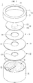
- FIG. 2 is an exploded perspective view of the rechargeable battery of FIG. 1
- FIG. 3 is a cross-sectional view taken along the line III-III of FIG. 1 .
- a rechargeable battery 1 includes an electrode assembly 10, a case 20, a cap assembly 30, and a housing 40.
- the cap assembly 30 includes a cap plate 31 and a terminal plate 33 that are combined together.
- the cap plate 31 and the terminal plate 33 are thermally fused by a thermal-fusion member 34 disposed between them.
- the present invention is not limited thereto.
- the thermal-fusion member 34 acts as a medium to connect the cap plate 31 and the terminal plate 33 to each other.
- the thermal fusion member 34 may be formed of an electrically insulating material, such as a polymer, and may be melted using a laser or the like to be fused to the cap plate 31 and the terminal plate 33.
- the present invention is not limited thereto.
- a coin cell Since a coin cell is manufactured in an ultra-compact size, it may have a design limitation in terms of space, and, accordingly, functionality is secured while simplifying a structure and a manufacturing process thereof. Regarding this, in the embodiment, insulation and coupling between the terminal plate 33 and the cap plate 31 through the heat-fusion member 34 are realized.
- the electrode assembly 10 includes a first electrode 11, which may be for example a negative electrode, and a second electrode 12, which may be for example a positive electrode, provided at respective sides of a separator 13 that is an electrically insulating material, and is formed by winding the first electrode 11, the separator 13, and the second electrode 12. Therefore, in an embodiment, the electrode assembly 10 may be formed as a jelly roll type. Although not shown separately, in an embodiment, the electrode assembly may be formed as a stack type. However, the present invention is not limited thereto.
- the electrode assembly 10 is configured to charge and discharge a current, and a winding axis in the electrode assembly 10 may be arranged parallel to a height direction, which is shown as a vertical direction in FIG. 1 to FIG. 3 , of the case 20.
- a first end which may be a lower surface of the electrode assembly, 101 and a second end, which may be an upper surface of the electrode assembly, 102 of the electrode assembly 10 may be flat and parallel to each other.
- the electrode assembly 10 is not provided with a center pin, but a center pin, which is not shown, may be provided at a position of the winding axis.
- the case 20 accommodates the electrode assembly 10 while facing the first end 101 of the electrode assembly 10.
- the electrode assembly 10 is covered with an insulating sheet 14 and is embedded in the case 20.
- the case 20 is formed as a cylinder that accommodates the jelly roll type of electrode assembly 10, and the cap assembly 30 seals an opening 21 of the cylindrical case 20.
- the electrode assembly 10 includes a first electrode tab 51 connected to, preferably directly connected to the first electrode 11 and a second electrode tab 52 connected to, preferably directly connected to the second electrode 12, and the first and second electrodes 11 and 12 are drawn out to the first and second ends 101 and 102, respectively.
- the first electrode tab 51 is electrically connected to, preferably directly connected to a bottom of the case 20, and the second electrode tab 52 is electrically connected to, preferably directly electrically connected to the terminal plate 33 of the cap assembly 30.
- the present invention is not limited thereto.
- the cap plate 31 of the cap assembly 30, while facing the second end 102 of the electrode assembly 10, is coupled to, preferably directly coupled to the case 20 to cover, preferably fully cover the opening 21.
- the terminal plate 33 is coupled to, preferably directly coupled to the second electrode tab 52 while being coupled to, preferably directly coupled to the cap plate 31 with the thermal-fusion member 34.
- the present invention is not limited thereto.
- first electrode 11 and the second electrode 12 are respectively a negative electrode and a positive electrode
- first electrode 11 and the second electrode 12 may respectively be a positive electrode and a negative electrode.
- present invention is not limited thereto.
- the first electrode 11 is a negative electrode and is formed in a long extending strip shape, and includes a negative coated portion that is a region in which a negative active material layer is coated to a current collector of a metal foil, wherein the metal foil may be for example a copper foil, and a negative uncoated portion that is a region in which an active material is not coated.
- the negative uncoated portion may be disposed at an end portion in a length direction of the negative electrode.
- the present invention is not limited thereto.
- the second electrode 12 is the positive electrode and is formed in a long extending strip shape, and includes a positive electrode coated portion that is a region in which a positive active material layer is coated to a current collector of a metal foil, wherein the metal foil may be for example an aluminum foil, and a positive uncoated portion that is a region in which an active material is not coated.
- the positive uncoated portion may be disposed at an end portion in a length direction of the positive electrode.
- the present invention is not limited thereto.
- the case 20 allows the electrode assembly 10 to be inserted into the opening 21 formed at one side thereof, and has a space for accommodating the electrode assembly 10 and an electrolyte therein.
- the case 20 may be formed in a cylindrical shape having a height H less than a diameter D thereof, and may have a circular opening 21 such that the cylindrical electrode assembly 10 corresponding to an inner space thereof may be inserted.
- the terminal plate 33 includes a flange part 331 and a protruded terminal 332.
- the flange part 331 is disposed between, preferably directly between the cap plate 31 and the electrode assembly 10 to be electrically insulated from and attached to, preferably directly attached to the inner surface of the cap plate 31.
- the present invention is not limited thereto.
- the housing 40 is provided to prevent or substantially prevent a reverse direction insertion when assembling the rechargeable battery 1 into a set.
- the housing 40 covers, preferably fully covers the cap plate 31 and is bonded to, preferably directly bonded to the case 20 to form an extension part P1 in the rechargeable battery 1. That is, the housing 40 forms a step on the side of the case 20 by the extension part P1.
- the present invention is not limited thereto.
- the housing 40 defines both sides of the height direction, which may be the up-down direction, of the rechargeable battery 1 as an extension part P1 on the upper side and a non-extension part P2 on the lower side. That is, in the rechargeable battery 1, the portion where the housing 40 is coupled, preferably directly coupled forms the extension part P1, and the portion without the housing 40 forms the non-extension part P2.
- the present invention is not limited thereto.
- the case 20 has a negative property of the first electrode 11, and, in the extension part P1, the terminal plate 33 has a positive property of the second electrode 12.
- the cap plate 31 coupled to, preferably directly coupled to the case 20 has the negative property of the first electrode 11 together with the case 20. That is, the cap plate 31 and the case 20 are electrically connected to each other, preferably directly electrically connected to each other.
- the present invention is not limited thereto.
- the protruded terminal 332 is protruded from the center of the flange part 331 to the outside and penetrates a terminal hole 311 of the cap plate 31, a through hole 341 of the thermal-fusion member 34, and a through hole 411 of the housing 40, and an inner surface of the protruded terminal 332 is electrically connected to, preferably directly electrically connected to the second electrode tab 52.
- the second electrode tab 52 may be connected to, preferably directly connected to an inner surface of the flange part 331 or the inner surface of the protruded terminal 332, or may be connected to, preferably directly connected to both.
- the protruded terminal 332 is protruded more with a first height difference ⁇ H1 than an outer surface of the housing 40 to form an outer surface. That is, the outer surface of the protruded terminal 332 is more protruded than an outer surface of the cap plate 31 with reference to a bottom of the case 20. Further, the outer surface of the protruded terminal 332 and the outer surface of the housing 40 form planes spaced apart from each other in the diameter direction while having the first height difference ⁇ H1.
- the housing 40 includes a planar part 41 and a side part 42.
- the planar part 41 is configured to cover, preferably fully cover the outer surface of the cap plate 31 while exposing the protruded terminal 332 through the through hole 411.
- the side part 42 extends along the side of the case 20 on the outer side of the planar part 41 to accommodate a part of the case 20 side and to be coupled to, preferably directly coupled to the side of the case 20.
- the part where the housing 40 is combined forms the extension part P1
- the part without the housing 40 forms the non-extension part P2.
- the present invention is not limited thereto..
- the housing 40 forms a step on the side of the case 20 at a boundary between the extension part P1 and the non-extension part P2 in the height direction and a crossing direction (the diameter direction) orthogonal to the height direction. That is, the extension part P1 relatively increases the height or the diameter compared to the non-extension part P2.
- the present invention is not limited thereto.
- the housing 40 is not combined at the lower part, thereby setting the exterior diameter of the case 20 between the exterior sides in the diameter direction of the case 20.
- the housing 40 is coupled to, preferably directly coupled to the upper part of the case 20 to set the exterior diameter of the housing 40 between the exterior sides in the diameter direction of the housing 40.
- the exterior diameter of the housing 40 is larger than the exterior diameter of the case 20. Therefore, there is a difference in diameter between the upper part and the lower part of the rechargeable battery 1.
- the present invention is not limited thereto.
- the housing 40 may be formed of an electrically insulating material to prevent or substantially prevent an electrical short circuit between the outer surface of the protruded terminal 332 and the outer surface of the cap plate 31.
- the housing 40 may be formed of polypropylene (PP), polyethylene (PE), polyethylene terephthalate (PET), polyethylene naphthalate (PEN) resin, or rubber.
- PP polypropylene
- PE polyethylene
- PET polyethylene terephthalate
- PEN polyethylene naphthalate
- any of synthetic resins or electrically insulating materials may be applied to the housing.
- the through hole 411 of the housing 40 is concentric with the terminal hole 311 of the cap plate 31, and an interior diameter of the through hole 411 is formed larger than an exterior diameter D11 of the protruded terminal 332. Therefore, the interior diameter D1 of the case 20 is larger than the sum of the exterior diameter D11 of the protruded terminal 332 and two times a diameter direction distance D12 of the planar part 41 set on both sides of the diameter direction of the protruded terminal 332, which may be described by the relation "D1 > D11 + 2 ⁇ D12". That is, a first gap G1 exists between the outer surface of the protruded terminal 332 and the inner wall of the through hole 411 of the housing 40.
- the first gap G1 prevents or substantially prevents the protruded terminal 332 from obstructing the area around the through hole 411 when the side part 42 of the housing 40 is coupled to, preferably directly coupled to the case 20 and the planar part 41 is in close contact with the cap plate 31.
- the present invention is not limited thereto.
- an insulating member 61 disposed in the outer circumference in the diameter direction of the thermal-fusion member 34 is installed on, preferably directly installed on the inner surface of the cap plate 31.
- the insulating member 61 may form an electrically insulating structure between the cap plate 31 and the second electrode tab 52 and between the cap plate 31 and the electrode assembly 10.
- the insulating member 61 has a through hole 611 corresponding to the exterior diameter of the thermal-fusion member 34.
- the diameter direction length D12 of the planar part 41 may be greater than or equal to a length H1 of the height direction of the side part 42 (D12 ⁇ H1). Therefore, the length H1 in the height direction creates a fastening force for the case 20 of the housing 40, and the length D12 in the diameter direction allows insulation performance of the terminal plate 33 to be sufficiently secured.
- the height H is set as the distance between the outer planes of the case 20 and the protruded terminal 332 in the state that the opening 21 of the case 20 is closed and sealed by the cap assembly 30, and the battery diameter D is set with the exterior circumference of the housing 40.
- a ratio of the height H to the battery diameter D is 1 or less (H/D ⁇ 1), or 0.9 or less (H/D ⁇ 0.9), or 0.8 or less (H/D ⁇ 0.8). Therefore, the rechargeable battery 1 of the embodiment may be a coin-type battery or a button-type battery and may form a thin coin or button shape.
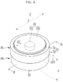
- FIG. 4 is a perspective view of a rechargeable battery according to an embodiment of the present invention
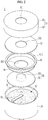
- FIG. 5 is an exploded perspective view of the rechargeable battery of FIG. 4
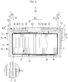
- FIG. 6 is a cross-sectional view taken along the line VI-VI of FIG. 4 .
- a terminal plate 63 of a cap assembly 60 includes a flange part 631 and a tab connection part 632.
- the flange part 631 is disposed on, preferably directly disposed on the outside of the cap plate 31 and is electrically insulated from and attached to an outer surface of the cap plate 31.
- the present invention is not limited thereto.
- a housing 70 is provided to prevent or substantially prevent a reverse direction insertion when assembling the rechargeable battery 2 into a set.
- the housing 70 covers, preferably fully covers the cap plate 31 and is coupled to the case 20 to form an extension part P3 in the rechargeable battery 2.
- a part of the outer surface is covered with, preferably fully covered with the flange part 631, and a flat surface, which is an exposed surface 301, of a remaining part of the outer surface is covered with, preferably fully covered with the housing 70.
- the present invention is not limited thereto.
- the tab connection part 632 is protruded from the center of the flange part 631 to the inside and penetrates the through hole 711 of the housing 70, the through hole 341 of the thermal-fusion member 34, and the terminal hole 311 of the cap plate 31 to be protruded toward the electrode assembly 10, and the second electrode tab 52 is electrically connected to, preferably directly electrically connected to the inner surface of the tab connection part 632.
- the present invention is not limited thereto.
- the flange part 631 is protruded more with a second height difference ⁇ H2 than the outer surface of the housing 70 to form the outer surface.
- the outer surface of the flange part 631 is more protruded than the outer surface of the cap plate 31 with reference to the bottom of the case 20.
- the outer surface of the flange part 631 and the outer surface of the housing 70 form planes spaced apart from each other in the diameter direction while having the second height difference ⁇ H2.
- the present invention is not limited thereto.
- the housing 70 includes a planar part 71 and a side part 72.
- the planar part 71 has a through hole 711 and is configured to cover, preferably fully cover the exposed surface 301 of the outer surface of the cap plate 31 while exposing the flange part 631 of the terminal plate 63.
- the side part 72 extends along the side of the case 20 at the outside of the planar part 71 to cover a part of the side of the case 20 and to be coupled, preferably to be directly coupled to to the side of case 20.
- a part where the housing 70 is combined with the case 20 forms the extension part P3, and a part without the housing 70 forms a non-extension part P4.
- the present invention is not limited thereto.
- the housing 70 covers, preferably fully covers the exposed surface 301 of the cap plate 31 and is bonded to, preferably directly bonded to the case 20 to form the extension part P3. That is, the housing 70 forms a step on the side of the case 20 by the extension part P3. That is, the extension part P3 relatively increases the height or the diameter compared to the non-extension part P4.
- the through hole 711 of the housing 70 is concentric with the terminal hole 311 of the cap plate 31, and the interior diameter of the through hole 711 is formed larger than an exterior diameter D21 of the flange part 631. Therefore, an interior diameter D2 of the case 20 is larger than the sum of the exterior diameter D21 of the protruded terminal 631 and two times a diameter direction distance D22 of the planar part 71 set on both sides of the diameter direction of the flange part 631, which may be described by the relation "D2 > D21 + 2 x D22".
- a second gap G2 exists between the outer surface of the flange part 631 and the inner wall of the through hole 711 of the housing 70.
- the insulating member 62 disposed in the diameter direction exterior circumference of the tab connection part 632 is installed on, preferably directly installed on the inner surface of the cap plate 31.
- the insulating member 62 may form an electrically insulating structure between the cap plate 31 and the second electrode tab 52 and between the cap plate 31 and the electrode assembly 10.
- the insulating member 62 has a through hole 621 corresponding to the terminal hole 311 of the cap plate 31.
- the through hole 621 allows the second electrode tab 52 to be connected to the inner surface of the tab connection part 632.
- the through hole 621 is formed with a smaller diameter than the terminal hole 311, thereby preventing or substantially preventing the second electrode tab 52 from being in contact with the cap plate 31.
- the present invention is not limited thereto.
- the diameter direction length D22 of the planar part 71 may be less than or equal to a length H2 of the height direction of the side part 72 (D22 ⁇ H2). Therefore, compared to the diameter direction length D12 of the first embodiment, the diameter direction length D22 is shorter, but the length H2 in the height direction allows for sufficiently securing the fastening force in the case 20 of the housing 70.
- the present invention is not limited thereto.
Landscapes
- Chemical & Material Sciences (AREA)
- Chemical Kinetics & Catalysis (AREA)
- Electrochemistry (AREA)
- General Chemical & Material Sciences (AREA)
- Engineering & Computer Science (AREA)
- Manufacturing & Machinery (AREA)
- Sealing Battery Cases Or Jackets (AREA)
- Connection Of Batteries Or Terminals (AREA)
- Battery Mounting, Suspending (AREA)
- Telephone Set Structure (AREA)
Abstract
A rechargeable battery includes: a case receiving an electrode assembly and including an opening; a cap assembly including a cap plate coupled to the case and covering the opening, and a terminal plate coupled to the cap plate; and a housing covering the cap plate and coupled to the case, and an outer surface of the terminal plate protrudes more than an outer surface of the housing to have a height difference.
Description
- Aspects of embodiments of the present invention relate to a rechargeable battery.
- A rechargeable battery can be repeatedly charged and discharged, unlike a primary battery that cannot be recharged. A low-capacity rechargeable battery is used for portable small-sized electronic devices, such as mobile phones, notebook computers, and camcorders. A large-capacity battery is widely used as a power source for driving motors, such as for hybrid vehicles.
- A representative rechargeable battery includes a nickel-cadmium (Ni-Cd) battery, a nickel-hydrogen (Ni-MH) battery, a lithium (Li) battery, and a lithium ion (Li-ion) rechargeable battery. Particularly, the lithium ion secondary battery has a higher operation voltage than the nickel-cadmium battery or the nickel-hydrogen battery that is mainly used as a portable electric equipment power source by about three times. Also, the lithium ion secondary battery is widely used in that energy density per unit weight is high.
- In particular, as a demand for wearable devices, such as headphones, earphones, smartwatches, and body-mounted medical devices which use Bluetooth, has increased, the need for rechargeable batteries of which energy density is high and which are ultra-small is increasing.
- The ultra-small rechargeable battery has aspects of securing required electrical capacity within a limited size, implementing an efficient structure while improving an effective low weight, and improving structural stability.
- The above information disclosed in this Background section is only for enhancement of understanding of the background of the invention, and, therefore, it may contain information that does not form the prior art that is already known in this country to a person of ordinary skill in the art.
- According to an aspect of embodiments of the present invention, an ultra-small rechargeable battery is provided. According to an aspect of embodiments of the present invention, a rechargeable battery that may prevent a reverse direction insertion when inserting to a set and may prevent an external short circuit of parts with different polarities, e.g. a terminal plate and a cap plate or a case, is provided.
- According to another aspect of embodiments of the present invention, a rechargeable battery is provided in which a terminal plate and a case having different polarities may be smoothly contacted with a set when being inserted into the set.
- According to one or more embodiments of the present invention, a rechargeable battery includes: a case receiving an electrode assembly and including an opening; a cap assembly including a cap plate coupled to, preferably directly coupled to the case and covering, preferably fully covering the opening, and a terminal plate coupled to, preferably directly coupled to the cap plate; and a housing covering, preferably fully covering the cap plate and coupled to the case, wherein an outer surface of the terminal plate protrudes more than an outer surface of the housing to have a height difference.
- The electrode assembly may include a first electrode, a second electrode, and a separator therebetween, the case may be connected to, preferably directly connected to the first electrode by a first electrode tab, and the terminal plate may be connected to, preferably directly connected to the second electrode by a second electrode tab.
- The cap plate may be electrically connected to, preferably directly electrically connected to the case, and the cap plate and the terminal plate may be thermally fused with a thermal-fusion member located therebetween and may be electrically insulated from each other.
- The terminal plate may include: a flange part disposed between, preferably directly between the cap plate and the electrode assembly and electrically insulated from and attached to, preferably directly attached to an inner surface of the cap plate; and a protruded terminal protruded from a center of the flange part to the outside, penetrating a terminal hole of the cap plate and a through hole of the housing, and electrically connected to, preferably directly electrically connected to the second electrode tab by an inner surface of the terminal plate, and the protruded terminal may protrude more than the outer surface of the housing by a first height difference to form an outer surface of the rechargeable battery.
- The housing may include: a planar part that covers, preferably fully covers an outer surface of the cap plate; and a side part extending along a side of the case at an outside of the planar part to cover a part of the side of the case and to be coupled to, preferably to be directly coupled to the side of the case.
- The housing may be formed of an electrically insulating material to prevent an electrical short circuit between the outer surface of the protruded terminal and the outer surface of the cap plate.
- The through hole of the housing may be concentric with the terminal hole of the cap plate, and an interior diameter of the through hole may be larger than an exterior diameter of the protruded terminal.
- An interior diameter of the case may be larger than a sum of the exterior diameter of the protruded terminal and two times a diameter direction distance of the planar part set on both sides in a diameter direction of the protruded terminal.
- The housing may include PP, PE, PET, PEN resin, or rubber.
- The terminal plate may include: a flange part on an outer surface of the cap plate and electrically insulated and attached to, preferably directly attached to the outer surface of the cap plate; and a tab connection part that is protruded from the center of the flange part to the inside and that is protruded toward the electrode assembly through a through hole of the housing and a terminal hole of the cap plate, and is electrically connected to, preferably directly electrically connected to the second electrode tab by an inner surface of the terminal plate, and the flange part may protrude more than the outer surface of the housing by a second height difference to form an outer surface of the rechargeable battery.
- The housing may include: a planar part including a through hole having a larger interior diameter than an exterior diameter of the flange part to cover, preferably fully cover an exposed surface of the cap plate while exposing the flange part; and a side part extending along a side of the case at an outside of the planar part to cover a part of the side of the case and to be joined to the side of the case.
- An interior diameter of the case may be larger than a sum of the exterior diameter of the flange part and two times a diameter direction distance of the planar part set on both sides in a diameter direction of the flange part.
- The housing may form a step on a side of the case.
- The case may set a first diameter in a diameter direction at a lower part of the case, and the housing may be coupled to, preferably directly coupled to an upper part of the case and set a second diameter larger than the first diameter in the diameter direction.
- As set forth above, the rechargeable battery according to one or more embodiments of the present invention forms a step on the side of the case because the housing covers the cap plate and is coupled to the case. In other words, since the housing protrudes more than the side of the case at the cap plate and its adjacent side, the step in which the height or diameter is increased may be formed. Therefore, visually or structurally, a reverse direction insertion of the rechargeable battery into a set may be effectively prevented.
- In the rechargeable battery according to one or more embodiments, two parts, e.g. the cap plate and the terminal plate, with different polarities in the cap assembly are exposed in the same direction, and the housing may cover, preferably fully cover at least one of two parts with different polarities. When the housing is formed of an electrically insulating material, an external short circuit of two parts by a conductive particle may be effectively prevented.
- Further, since the rechargeable battery according to one or more embodiments combines the housing to the case, the housing acts as a buffer against a physical impact, such that safety may be improved in a drop test and a tumbling test.
- In the rechargeable battery according to one or more embodiments, the terminal plate is protruded more than the housing despite the application of the housing, such that the terminal plate and the case may be in smooth contact with a set when being inserted into the set.
-
-
FIG. 1 is a perspective view of a rechargeable battery according to an embodiment of the present invention. -
FIG. 2 is an exploded perspective view of the rechargeable battery ofFIG. 1 . -
FIG. 3 is a cross-sectional view taken along the line III-III ofFIG. 1 . -
FIG. 4 is a perspective view of a rechargeable battery according to an embodiment of the present invention. -
FIG. 5 is an exploded perspective view of the rechargeable battery ofFIG. 4 . -
FIG. 6 is a cross-sectional view taken along the line VI-VI ofFIG. 4 . -
1, 2: rechargeable battery 10: electrode assembly 11: first electrode 12: second electrode 13: separator 14: insulating sheet 20: case 21: opening 30, 60: cap assembly 31: cap plate 33, 63: terminal plate 34: thermal- fusion member 40, 70: housing 41, 71: planar part 42, 72: side part 51: first electrode tab 52: second electrode tab 61, 62: insulating member 611, 621: through hole 101: first end 102: second end 301: exposed surface 311: terminal hole 331, 631: flange part 332, 632: protruded terminal 341: through hole 411, 711: through hole D: battery diameter D1, D2: interior diameter D11, D21: exterior diameter D12, D22: diameter direction distance H: height H1, H2: length of height direction G1, G2: first, second gap P1, P3: extension part P2, P4: non-extension part ΔH1, ΔH2: first, second height difference - The present invention will be described more fully hereinafter with reference to the accompanying drawings, in which exemplary embodiments of the invention are shown. As those skilled in the art would realize, the described embodiments may be modified in various different ways, all without departing from the scope of the present invention. The drawings and description are to be regarded as illustrative in nature and not restrictive. Like reference numerals designate like elements throughout the specification.
- In addition, unless explicitly described to the contrary, it is to be understood that terms such as "comprises," "includes," or "have" used in the present specification specify the presence of stated features, numerals, steps, operations, components, parts, or a combination thereof, but do not preclude the presence or addition of one or more other features, numerals, steps, operations, components, parts, or a combination thereof.
- Also, in this specification, it is to be understood that when one component is referred to as being "connected" or "coupled" to another component, it may be connected or coupled directly to the other component or connected or coupled to another component with one or more other components intervening therebetween.
- Singular forms are to include plural forms unless the context clearly indicates otherwise.
- It is to be understood that, although the terms "first," "second," etc. may be used herein to describe various elements, these elements should not be limited by these terms. These terms are used to distinguish one element from another. For example, a first element could be termed a "second" element, and, similarly, a second element could be termed a "first" element, without departing from the scope of example embodiments of the inventive concept. The terms of a singular form may include plural forms unless the context clearly indicates otherwise.
- In addition, terms such as "below," "lower," "above," "upper," and the like are used to describe the relationship of the configurations shown in the drawings. However, the terms are used as a relative concept and are described with reference to the direction indicated in the drawings.
- Unless otherwise defined, all terms (including technical and scientific terms) used herein have the same meaning as commonly understood by one of ordinary skill in the art to which the inventive concept pertains. It is also to be understood that terms defined in commonly used dictionaries should be interpreted as having meanings consistent with the meanings in the context of the related art, and are expressly defined herein unless they are interpreted in an ideal or overly formal sense.
- A rechargeable battery according to an embodiment of the present invention, which is an ultra-compact battery, may be a coin cell or a button cell. Here, the coin cell or the button cell is a thin coin-type or button-type cell, and refers to a battery having a ratio H/D of a height H to a diameter D of 1 or less, 0.9 or less, or 0.8 or less, see
FIG. 1 for an exemplary illustration. - In an embodiment, the coin cell or the button cell is mainly cylindrical, and a horizontal cross-section is circular, but the present invention is not limited thereto, and a horizontal cross-section may be oval or polygonal. In this case, a diameter is determined as a maximum distance of a housing's or a case's exterior circumference based on the horizontal direction of the battery, and a height is determined as a maximum distance, in other words a distance from a flat bottom to a flat top cross-section, based on the vertical direction of the battery.
- However, the present invention is not limited to the coin cell or the button cell that is an example of the present invention, and a battery of the present invention may be a cylindrical-type or pin-type battery. Herein, a case in which a rechargeable battery according to an embodiment of the present invention is a coin cell or a button cell will be described as an example in further detail.
-
FIG. 1 is a perspective view of a rechargeable battery according to an embodiment of the present invention;FIG. 2 is an exploded perspective view of the rechargeable battery ofFIG. 1 ; andFIG. 3 is a cross-sectional view taken along the line III-III ofFIG. 1 . - Referring to
FIG. 1 to FIG. 3 , arechargeable battery 1 according to an embodiment includes anelectrode assembly 10, acase 20, acap assembly 30, and ahousing 40. Thecap assembly 30 includes acap plate 31 and aterminal plate 33 that are combined together. As an example, thecap plate 31 and theterminal plate 33 are thermally fused by a thermal-fusion member 34 disposed between them. However, the present invention is not limited thereto. - The thermal-
fusion member 34 acts as a medium to connect thecap plate 31 and theterminal plate 33 to each other. For example, thethermal fusion member 34 may be formed of an electrically insulating material, such as a polymer, and may be melted using a laser or the like to be fused to thecap plate 31 and theterminal plate 33. However, the present invention is not limited thereto. - In an embodiment, by coupling the
terminal plate 33 to thecap plate 31 with thethermal fusion member 34, it is possible to form a stable coupling structure while effectively insulating between theterminal plate 33 and thecap plate 31 without adding a separate insulating configuration. - Since a coin cell is manufactured in an ultra-compact size, it may have a design limitation in terms of space, and, accordingly, functionality is secured while simplifying a structure and a manufacturing process thereof. Regarding this, in the embodiment, insulation and coupling between the
terminal plate 33 and thecap plate 31 through the heat-fusion member 34 are realized. - The
electrode assembly 10 includes afirst electrode 11, which may be for example a negative electrode, and asecond electrode 12, which may be for example a positive electrode, provided at respective sides of aseparator 13 that is an electrically insulating material, and is formed by winding thefirst electrode 11, theseparator 13, and thesecond electrode 12. Therefore, in an embodiment, theelectrode assembly 10 may be formed as a jelly roll type. Although not shown separately, in an embodiment, the electrode assembly may be formed as a stack type. However, the present invention is not limited thereto. - The
electrode assembly 10 is configured to charge and discharge a current, and a winding axis in theelectrode assembly 10 may be arranged parallel to a height direction, which is shown as a vertical direction inFIG. 1 to FIG. 3 , of thecase 20. In an embodiment, a first end, which may be a lower surface of the electrode assembly, 101 and a second end, which may be an upper surface of the electrode assembly, 102 of theelectrode assembly 10 may be flat and parallel to each other. In an embodiment, theelectrode assembly 10 is not provided with a center pin, but a center pin, which is not shown, may be provided at a position of the winding axis. - The
case 20 accommodates theelectrode assembly 10 while facing thefirst end 101 of theelectrode assembly 10. In an embodiment, theelectrode assembly 10 is covered with an insulatingsheet 14 and is embedded in thecase 20. As an example, thecase 20 is formed as a cylinder that accommodates the jelly roll type ofelectrode assembly 10, and thecap assembly 30 seals anopening 21 of thecylindrical case 20. - In an embodiment, the
electrode assembly 10 includes afirst electrode tab 51 connected to, preferably directly connected to thefirst electrode 11 and asecond electrode tab 52 connected to, preferably directly connected to thesecond electrode 12, and the first andsecond electrodes - In a state in which the
electrode assembly 10 is accommodated in thecase 20, thefirst electrode tab 51 is electrically connected to, preferably directly connected to a bottom of thecase 20, and thesecond electrode tab 52 is electrically connected to, preferably directly electrically connected to theterminal plate 33 of thecap assembly 30. However, the present invention is not limited thereto. - In addition, the
cap plate 31 of thecap assembly 30, while facing thesecond end 102 of theelectrode assembly 10, is coupled to, preferably directly coupled to thecase 20 to cover, preferably fully cover theopening 21. In this way, theterminal plate 33 is coupled to, preferably directly coupled to thesecond electrode tab 52 while being coupled to, preferably directly coupled to thecap plate 31 with the thermal-fusion member 34. However, the present invention is not limited thereto. - Herein, a case in which the
first electrode 11 and thesecond electrode 12 are respectively a negative electrode and a positive electrode will be described as an example, but the present invention is not limited thereto, and thefirst electrode 11 and thesecond electrode 12 may respectively be a positive electrode and a negative electrode. However, the present invention is not limited thereto. - In an embodiment, the
first electrode 11 is a negative electrode and is formed in a long extending strip shape, and includes a negative coated portion that is a region in which a negative active material layer is coated to a current collector of a metal foil, wherein the metal foil may be for example a copper foil, and a negative uncoated portion that is a region in which an active material is not coated. The negative uncoated portion may be disposed at an end portion in a length direction of the negative electrode. However, the present invention is not limited thereto. - In an embodiment, the
second electrode 12 is the positive electrode and is formed in a long extending strip shape, and includes a positive electrode coated portion that is a region in which a positive active material layer is coated to a current collector of a metal foil, wherein the metal foil may be for example an aluminum foil, and a positive uncoated portion that is a region in which an active material is not coated. The positive uncoated portion may be disposed at an end portion in a length direction of the positive electrode. However, the present invention is not limited thereto. - The
case 20 allows theelectrode assembly 10 to be inserted into theopening 21 formed at one side thereof, and has a space for accommodating theelectrode assembly 10 and an electrolyte therein. For example, thecase 20 may be formed in a cylindrical shape having a height H less than a diameter D thereof, and may have acircular opening 21 such that thecylindrical electrode assembly 10 corresponding to an inner space thereof may be inserted. - In the
cap assembly 30, theterminal plate 33 includes aflange part 331 and aprotruded terminal 332. Theflange part 331 is disposed between, preferably directly between thecap plate 31 and theelectrode assembly 10 to be electrically insulated from and attached to, preferably directly attached to the inner surface of thecap plate 31. However, the present invention is not limited thereto. - The
housing 40 is provided to prevent or substantially prevent a reverse direction insertion when assembling therechargeable battery 1 into a set. As an example, thehousing 40 covers, preferably fully covers thecap plate 31 and is bonded to, preferably directly bonded to thecase 20 to form an extension part P1 in therechargeable battery 1. That is, thehousing 40 forms a step on the side of thecase 20 by the extension part P1. However, the present invention is not limited thereto. - Therefore, the
housing 40 defines both sides of the height direction, which may be the up-down direction, of therechargeable battery 1 as an extension part P1 on the upper side and a non-extension part P2 on the lower side. That is, in therechargeable battery 1, the portion where thehousing 40 is coupled, preferably directly coupled forms the extension part P1, and the portion without thehousing 40 forms the non-extension part P2. However, the present invention is not limited thereto. - In the non-extension part P2, the
case 20 has a negative property of thefirst electrode 11, and, in the extension part P1, theterminal plate 33 has a positive property of thesecond electrode 12. In an embodiment, thecap plate 31 coupled to, preferably directly coupled to thecase 20 has the negative property of thefirst electrode 11 together with thecase 20. That is, thecap plate 31 and thecase 20 are electrically connected to each other, preferably directly electrically connected to each other. However, the present invention is not limited thereto. - In the
terminal plate 33, the protrudedterminal 332 is protruded from the center of theflange part 331 to the outside and penetrates aterminal hole 311 of thecap plate 31, a throughhole 341 of the thermal-fusion member 34, and a throughhole 411 of thehousing 40, and an inner surface of the protrudedterminal 332 is electrically connected to, preferably directly electrically connected to thesecond electrode tab 52. Thesecond electrode tab 52 may be connected to, preferably directly connected to an inner surface of theflange part 331 or the inner surface of the protrudedterminal 332, or may be connected to, preferably directly connected to both. - The protruded
terminal 332 is protruded more with a first height difference ΔH1 than an outer surface of thehousing 40 to form an outer surface. That is, the outer surface of the protrudedterminal 332 is more protruded than an outer surface of thecap plate 31 with reference to a bottom of thecase 20. Further, the outer surface of the protrudedterminal 332 and the outer surface of thehousing 40 form planes spaced apart from each other in the diameter direction while having the first height difference ΔH1. - In an embodiment, the
housing 40 includes aplanar part 41 and aside part 42. Theplanar part 41 is configured to cover, preferably fully cover the outer surface of thecap plate 31 while exposing the protruded terminal 332 through the throughhole 411. Theside part 42 extends along the side of thecase 20 on the outer side of theplanar part 41 to accommodate a part of thecase 20 side and to be coupled to, preferably directly coupled to the side of thecase 20. In therechargeable battery 1, the part where thehousing 40 is combined forms the extension part P1, and the part without thehousing 40 forms the non-extension part P2. However, the present invention is not limited thereto.. - Therefore, the
housing 40 forms a step on the side of thecase 20 at a boundary between the extension part P1 and the non-extension part P2 in the height direction and a crossing direction (the diameter direction) orthogonal to the height direction. That is, the extension part P1 relatively increases the height or the diameter compared to the non-extension part P2. However, the present invention is not limited thereto. - In the
case 20, thehousing 40 is not combined at the lower part, thereby setting the exterior diameter of thecase 20 between the exterior sides in the diameter direction of thecase 20. Thehousing 40 is coupled to, preferably directly coupled to the upper part of thecase 20 to set the exterior diameter of thehousing 40 between the exterior sides in the diameter direction of thehousing 40. The exterior diameter of thehousing 40 is larger than the exterior diameter of thecase 20. Therefore, there is a difference in diameter between the upper part and the lower part of therechargeable battery 1. However, the present invention is not limited thereto. - In an embodiment, the
housing 40 may be formed of an electrically insulating material to prevent or substantially prevent an electrical short circuit between the outer surface of the protrudedterminal 332 and the outer surface of thecap plate 31. For example, thehousing 40 may be formed of polypropylene (PP), polyethylene (PE), polyethylene terephthalate (PET), polyethylene naphthalate (PEN) resin, or rubber. Although not illustrated, any of synthetic resins or electrically insulating materials may be applied to the housing. - In an embodiment, the through
hole 411 of thehousing 40 is concentric with theterminal hole 311 of thecap plate 31, and an interior diameter of the throughhole 411 is formed larger than an exterior diameter D11 of the protrudedterminal 332. Therefore, the interior diameter D1 of thecase 20 is larger than the sum of the exterior diameter D11 of the protrudedterminal 332 and two times a diameter direction distance D12 of theplanar part 41 set on both sides of the diameter direction of the protrudedterminal 332, which may be described by the relation "D1 > D11 + 2 × D12". That is, a first gap G1 exists between the outer surface of the protrudedterminal 332 and the inner wall of the throughhole 411 of thehousing 40. - The first gap G1 prevents or substantially prevents the protruded terminal 332 from obstructing the area around the through
hole 411 when theside part 42 of thehousing 40 is coupled to, preferably directly coupled to thecase 20 and theplanar part 41 is in close contact with thecap plate 31. However, the present invention is not limited thereto. - In an embodiment, an insulating
member 61 disposed in the outer circumference in the diameter direction of the thermal-fusion member 34 is installed on, preferably directly installed on the inner surface of thecap plate 31. The insulatingmember 61 may form an electrically insulating structure between thecap plate 31 and thesecond electrode tab 52 and between thecap plate 31 and theelectrode assembly 10. As an example, the insulatingmember 61 has a throughhole 611 corresponding to the exterior diameter of the thermal-fusion member 34. - In an embodiment, in the
housing 40, the diameter direction length D12 of theplanar part 41 may be greater than or equal to a length H1 of the height direction of the side part 42 (D12 ≥ H1). Therefore, the length H1 in the height direction creates a fastening force for thecase 20 of thehousing 40, and the length D12 in the diameter direction allows insulation performance of theterminal plate 33 to be sufficiently secured. - In an embodiment, referring to
FIG. 1 , in therechargeable battery 1, the height H is set as the distance between the outer planes of thecase 20 and the protruded terminal 332 in the state that theopening 21 of thecase 20 is closed and sealed by thecap assembly 30, and the battery diameter D is set with the exterior circumference of thehousing 40. In an embodiment, a ratio of the height H to the battery diameter D is 1 or less (H/D ≤ 1), or 0.9 or less (H/D ≤ 0.9), or 0.8 or less (H/D ≤ 0.8). Therefore, therechargeable battery 1 of the embodiment may be a coin-type battery or a button-type battery and may form a thin coin or button shape. - Herein, another embodiment of the present invention is described. By comparing the first and second embodiments, the description for the same configurations may be omitted, and different configurations are mainly described with respect to the second embodiment.
-
FIG. 4 is a perspective view of a rechargeable battery according to an embodiment of the present invention;FIG. 5 is an exploded perspective view of the rechargeable battery ofFIG. 4 ; andFIG. 6 is a cross-sectional view taken along the line VI-VI ofFIG. 4 . - Referring to
FIG. 4 to FIG. 6 , in arechargeable battery 2 according to an embodiment, aterminal plate 63 of acap assembly 60 includes aflange part 631 and atab connection part 632. Theflange part 631 is disposed on, preferably directly disposed on the outside of thecap plate 31 and is electrically insulated from and attached to an outer surface of thecap plate 31. However, the present invention is not limited thereto. - A
housing 70 is provided to prevent or substantially prevent a reverse direction insertion when assembling therechargeable battery 2 into a set. As an example, thehousing 70 covers, preferably fully covers thecap plate 31 and is coupled to thecase 20 to form an extension part P3 in therechargeable battery 2. On thecap plate 31, a part of the outer surface is covered with, preferably fully covered with theflange part 631, and a flat surface, which is an exposedsurface 301, of a remaining part of the outer surface is covered with, preferably fully covered with thehousing 70. However, the present invention is not limited thereto. - In the
terminal plate 63, thetab connection part 632 is protruded from the center of theflange part 631 to the inside and penetrates the throughhole 711 of thehousing 70, the throughhole 341 of the thermal-fusion member 34, and theterminal hole 311 of thecap plate 31 to be protruded toward theelectrode assembly 10, and thesecond electrode tab 52 is electrically connected to, preferably directly electrically connected to the inner surface of thetab connection part 632. However, the present invention is not limited thereto. - The
flange part 631 is protruded more with a second height difference ΔH2 than the outer surface of thehousing 70 to form the outer surface. In other words, the outer surface of theflange part 631 is more protruded than the outer surface of thecap plate 31 with reference to the bottom of thecase 20. Also, the outer surface of theflange part 631 and the outer surface of thehousing 70 form planes spaced apart from each other in the diameter direction while having the second height difference ΔH2. However, the present invention is not limited thereto. - For example, the
housing 70 includes aplanar part 71 and aside part 72. Theplanar part 71 has a throughhole 711 and is configured to cover, preferably fully cover the exposedsurface 301 of the outer surface of thecap plate 31 while exposing theflange part 631 of theterminal plate 63. Theside part 72 extends along the side of thecase 20 at the outside of theplanar part 71 to cover a part of the side of thecase 20 and to be coupled, preferably to be directly coupled to to the side ofcase 20. In therechargeable battery 2, a part where thehousing 70 is combined with thecase 20 forms the extension part P3, and a part without thehousing 70 forms a non-extension part P4. However, the present invention is not limited thereto. - The
housing 70 covers, preferably fully covers the exposedsurface 301 of thecap plate 31 and is bonded to, preferably directly bonded to thecase 20 to form the extension part P3. That is, thehousing 70 forms a step on the side of thecase 20 by the extension part P3. That is, the extension part P3 relatively increases the height or the diameter compared to the non-extension part P4. - In an embodiment, the through
hole 711 of thehousing 70 is concentric with theterminal hole 311 of thecap plate 31, and the interior diameter of the throughhole 711 is formed larger than an exterior diameter D21 of theflange part 631. Therefore, an interior diameter D2 of thecase 20 is larger than the sum of the exterior diameter D21 of the protrudedterminal 631 and two times a diameter direction distance D22 of theplanar part 71 set on both sides of the diameter direction of theflange part 631, which may be described by the relation "D2 > D21 + 2 x D22". - That is, a second gap G2 exists between the outer surface of the
flange part 631 and the inner wall of the throughhole 711 of thehousing 70. - The insulating
member 62 disposed in the diameter direction exterior circumference of thetab connection part 632 is installed on, preferably directly installed on the inner surface of thecap plate 31. The insulatingmember 62 may form an electrically insulating structure between thecap plate 31 and thesecond electrode tab 52 and between thecap plate 31 and theelectrode assembly 10. As an example, the insulatingmember 62 has a throughhole 621 corresponding to theterminal hole 311 of thecap plate 31. The throughhole 621 allows thesecond electrode tab 52 to be connected to the inner surface of thetab connection part 632. The throughhole 621 is formed with a smaller diameter than theterminal hole 311, thereby preventing or substantially preventing thesecond electrode tab 52 from being in contact with thecap plate 31. However, the present invention is not limited thereto. - In the
housing 70, the diameter direction length D22 of theplanar part 71 may be less than or equal to a length H2 of the height direction of the side part 72 (D22 ≤ H2). Therefore, compared to the diameter direction length D12 of the first embodiment, the diameter direction length D22 is shorter, but the length H2 in the height direction allows for sufficiently securing the fastening force in thecase 20 of thehousing 70. However, the present invention is not limited thereto. - While the present invention has been described in connection with what are presently considered to be some practical embodiments, it is to be understood that the invention is not limited to the disclosed embodiments. On the contrary, it is intended to cover various modifications and equivalent arrangements included within the scope of the appended claims.
Claims (14)
- A rechargeable battery (1, 2) comprising:a case (20) receiving an electrode assembly (10) and comprising an opening (21);a cap assembly (30, 60) comprising a cap plate (31) coupled to the case (20) and covering the opening (21), and a terminal plate (33, 63) coupled to the cap plate (31); anda housing (40, 70) covering the cap plate (31) and coupled to the case (20),wherein an outer surface of the terminal plate (33, 63) protrudes more than an outer surface of the housing (40, 70) to have a first height difference (ΔH1).
- The rechargeable battery (1, 2) of claim 1, wherein
the electrode assembly (10) comprises a first electrode (11), a second electrode (12), and a separator (13) therebetween,
the case (20) is connected to the first electrode (11) by a first electrode tab (51), and
the terminal plate (33, 63) is connected to the second electrode (12) by a second electrode tab (52). - The rechargeable battery (1, 2) of claim 2, wherein
the cap plate (31) is electrically connected to the case (20), and
the cap plate (31) and the terminal plate (33, 63) are thermally fused with a thermal-fusion member (34) therebetween and are electrically insulated from each other. - The rechargeable battery (1) of claim 2, wherein
the terminal plate (33) comprises:a flange part (331) located between the cap plate (31) and the electrode assembly (10), and the flange part (331) being electrically insulated and attached to an inner surface of the cap plate (31); anda protruded terminal (332) protruded from a center of the flange part (331) to the outside, penetrating a terminal hole (311) of the cap plate (31) and a through hole (411) of the housing (40), and electrically connected to the second electrode tab (52) by an inner surface of the terminal plate (33), andthe protruded terminal (332) protrudes more than the outer surface of the housing (40) by a first height difference to form an outer surface of the rechargeable battery (1). - The rechargeable battery (1) of claim 4, wherein the housing (40) comprises:a planar part (41) that covers an outer surface of the cap plate (31); anda side part (42) extending along a side of the case (20) at an outside of the planar part (41) configured to cover a part of the side of the case (20) and be coupled to the side of the case (20).
- The rechargeable battery (1) of claim 5, wherein the housing (40) is formed of an electrically insulating material.
- The rechargeable battery (1) of claim 6, wherein the through hole (411) of the housing (40) is concentric with the terminal hole (311) of the cap plate (31), and an interior diameter (D1) of the through hole (411) of the housing is larger than an exterior diameter (D11) of the protruded terminal (332).
- The rechargeable battery (1) of claim 5, wherein an interior diameter (D1) of the case (20) is larger than a sum of an exterior diameter (D11) of the protruded terminal (332) and two times a diameter direction distance (D12) of the planar part set (41) on both sides in a diameter direction of the protruded terminal (332).
- The rechargeable battery (2) of claim 2, wherein the terminal plate (63) comprises:a flange part (631) on an outer surface of the cap plate (31) and electrically insulated and attached to the outer surface of the cap plate (31); anda tab connection part (632) protruded from a center of the flange part (631) to the inside and protruded toward the electrode assembly (10) through a through hole (711) of the housing (70) and a terminal hole (311) of the cap plate (31), and electrically connected to the second electrode tab (52) by an inner surface of the terminal plate (63), andthe flange part (631) protrudes more than the outer surface of the housing (70) by a second height difference (ΔH2) to form an outer surface of the rechargeable battery (2).
- The rechargeable battery (2) of claim 9, wherein the housing (70) comprises:a planar part (71) comprising a through hole (711) having a larger interior diameter (D2) than an exterior diameter (D21) of the flange part (631) provided to cover an exposed surface (301) of the cap plate (31) while exposing the flange part (631); anda side part (72) extending along a side of the case (20) at an outside of the planar part (71) configured to cover a part of the side of the case (20) and to be joined to the side of the case (20).
- The rechargeable battery (2) of claim 10, wherein an interior diameter (D2) of the case (20) is larger than a sum of an exterior diameter (D21) of the flange part (631) and two times a diameter direction distance (D22) of the planar part (71) set on both sides in a diameter direction of the flange part (631).
- The rechargeable battery (1, 2) according to any of the preceding claims, wherein the housing (40, 70) comprises PP, PE, PET, a PEN resin, or rubber.
- The rechargeable battery (1, 2) according to any of the preceding claims, wherein the housing (40, 70) forms a step on a side of the case (20).
- The rechargeable battery (1, 2) according to any of the preceding claims, wherein
the case (20) sets a first diameter in a diameter direction at a lower part of the case (20), and
the housing (40, 70) is coupled to an upper part of the case (20) and sets a second diameter larger than the first diameter in the diameter direction.
Applications Claiming Priority (1)
| Application Number | Priority Date | Filing Date | Title |
|---|---|---|---|
| KR1020200073855A KR102960971B1 (en) | 2020-06-17 | Rechargeable battery |
Publications (1)
| Publication Number | Publication Date |
|---|---|
| EP3926739A1 true EP3926739A1 (en) | 2021-12-22 |
Family
ID=75746249
Family Applications (1)
| Application Number | Title | Priority Date | Filing Date |
|---|---|---|---|
| EP21171193.2A Pending EP3926739A1 (en) | 2020-06-17 | 2021-04-29 | Rechargeable battery |
Country Status (3)
| Country | Link |
|---|---|
| US (1) | US12224459B2 (en) |
| EP (1) | EP3926739A1 (en) |
| CN (1) | CN113809380B (en) |
Cited By (4)
| Publication number | Priority date | Publication date | Assignee | Title |
|---|---|---|---|---|
| EP3930064A1 (en) * | 2020-06-25 | 2021-12-29 | Samsung SDI Co., Ltd. | Rechargeable battery |
| CN114744377A (en) * | 2022-01-25 | 2022-07-12 | 广东微电新能源有限公司 | Button cell and electronic equipment |
| CN116470200A (en) * | 2023-04-28 | 2023-07-21 | 厦门海辰储能科技股份有限公司 | End cover assembly, energy storage device and electrical equipment |
| EP4350854A3 (en) * | 2022-10-04 | 2024-04-24 | Samsung SDI Co., Ltd. | Button cell |
Families Citing this family (4)
| Publication number | Priority date | Publication date | Assignee | Title |
|---|---|---|---|---|
| USD1096608S1 (en) * | 2020-06-29 | 2025-10-07 | Zhuhai Cosmx Battery Co., Ltd. | Button cell |
| USD1093278S1 (en) * | 2021-01-25 | 2025-09-16 | Zhuhai Cosmx Battery Co., Ltd. | Battery |
| USD1104945S1 (en) * | 2021-02-23 | 2025-12-09 | Zhuhai Cosmx Battery Co., Ltd. | Battery |
| CN219917360U (en) * | 2023-07-19 | 2023-10-27 | 宁德时代新能源科技股份有限公司 | Battery monomer, battery and electric equipment |
Citations (4)
| Publication number | Priority date | Publication date | Assignee | Title |
|---|---|---|---|---|
| US20170207491A1 (en) * | 2016-01-15 | 2017-07-20 | Seiko Instruments Inc. | Electrochemical cell |
| EP2416406B1 (en) * | 2010-08-05 | 2019-07-03 | Samsung SDI Co., Ltd. | Secondary battery |
| KR20200007559A (en) * | 2018-07-13 | 2020-01-22 | 주식회사 엘지화학 | Secondary battery and method for manufacturing the battery |
| KR20200020173A (en) * | 2018-08-16 | 2020-02-26 | 주식회사 엘지화학 | Rechargeable battery |
Family Cites Families (5)
| Publication number | Priority date | Publication date | Assignee | Title |
|---|---|---|---|---|
| US2332456A (en) * | 1940-10-03 | 1943-10-19 | Marathon Battery Company | Cell construction |
| US7341802B1 (en) * | 2004-03-25 | 2008-03-11 | Quallion Llc | Feedthrough assembly and method |
| KR102249892B1 (en) | 2014-10-08 | 2021-05-10 | 삼성에스디아이 주식회사 | Rechargeable battery |
| KR102337491B1 (en) | 2017-03-06 | 2021-12-09 | 삼성에스디아이 주식회사 | Secondary battery |
| KR102371195B1 (en) | 2017-04-07 | 2022-03-07 | 삼성에스디아이 주식회사 | Rechargeable Mattery And Rechargeable battery Module Using The Same |
-
2021
- 2021-03-16 US US17/202,881 patent/US12224459B2/en active Active
- 2021-04-20 CN CN202110424094.5A patent/CN113809380B/en active Active
- 2021-04-29 EP EP21171193.2A patent/EP3926739A1/en active Pending
Patent Citations (4)
| Publication number | Priority date | Publication date | Assignee | Title |
|---|---|---|---|---|
| EP2416406B1 (en) * | 2010-08-05 | 2019-07-03 | Samsung SDI Co., Ltd. | Secondary battery |
| US20170207491A1 (en) * | 2016-01-15 | 2017-07-20 | Seiko Instruments Inc. | Electrochemical cell |
| KR20200007559A (en) * | 2018-07-13 | 2020-01-22 | 주식회사 엘지화학 | Secondary battery and method for manufacturing the battery |
| KR20200020173A (en) * | 2018-08-16 | 2020-02-26 | 주식회사 엘지화학 | Rechargeable battery |
Cited By (5)
| Publication number | Priority date | Publication date | Assignee | Title |
|---|---|---|---|---|
| EP3930064A1 (en) * | 2020-06-25 | 2021-12-29 | Samsung SDI Co., Ltd. | Rechargeable battery |
| US12261308B2 (en) | 2020-06-25 | 2025-03-25 | Samsung Sdi Co., Ltd. | Button cell |
| CN114744377A (en) * | 2022-01-25 | 2022-07-12 | 广东微电新能源有限公司 | Button cell and electronic equipment |
| EP4350854A3 (en) * | 2022-10-04 | 2024-04-24 | Samsung SDI Co., Ltd. | Button cell |
| CN116470200A (en) * | 2023-04-28 | 2023-07-21 | 厦门海辰储能科技股份有限公司 | End cover assembly, energy storage device and electrical equipment |
Also Published As
| Publication number | Publication date |
|---|---|
| US20210399392A1 (en) | 2021-12-23 |
| CN113809380A (en) | 2021-12-17 |
| CN113809380B (en) | 2025-02-25 |
| KR20210156118A (en) | 2021-12-24 |
| US12224459B2 (en) | 2025-02-11 |
Similar Documents
| Publication | Publication Date | Title |
|---|---|---|
| US12347891B2 (en) | Button cell comprising a direction determining member | |
| US12224459B2 (en) | Button cell | |
| US12261308B2 (en) | Button cell | |
| CN113224366B (en) | Rechargeable battery | |
| KR102593582B1 (en) | Rechargeable battery | |
| US20220223984A1 (en) | Rechargeable battery | |
| US20240274992A1 (en) | Rechargeable battery | |
| US20250266540A1 (en) | Button cell | |
| EP4007026A1 (en) | Rechargeable battery | |
| EP4145597A1 (en) | Rechargeable battery | |
| KR102960971B1 (en) | Rechargeable battery | |
| KR102960973B1 (en) | Rechargeable battery |
Legal Events
| Date | Code | Title | Description |
|---|---|---|---|
| PUAI | Public reference made under article 153(3) epc to a published international application that has entered the european phase |
Free format text: ORIGINAL CODE: 0009012 |
|
| STAA | Information on the status of an ep patent application or granted ep patent |
Free format text: STATUS: REQUEST FOR EXAMINATION WAS MADE |
|
| 17P | Request for examination filed |
Effective date: 20210429 |
|
| AK | Designated contracting states |
Kind code of ref document: A1 Designated state(s): AL AT BE BG CH CY CZ DE DK EE ES FI FR GB GR HR HU IE IS IT LI LT LU LV MC MK MT NL NO PL PT RO RS SE SI SK SM TR |
|
| B565 | Issuance of search results under rule 164(2) epc |
Effective date: 20211014 |
|
| STAA | Information on the status of an ep patent application or granted ep patent |
Free format text: STATUS: EXAMINATION IS IN PROGRESS |
|
| 17Q | First examination report despatched |
Effective date: 20221130 |