EP3926738A1 - Battery - Google Patents
Battery Download PDFInfo
- Publication number
- EP3926738A1 EP3926738A1 EP21164293.9A EP21164293A EP3926738A1 EP 3926738 A1 EP3926738 A1 EP 3926738A1 EP 21164293 A EP21164293 A EP 21164293A EP 3926738 A1 EP3926738 A1 EP 3926738A1
- Authority
- EP
- European Patent Office
- Prior art keywords
- battery
- housing
- battery cell
- elastic layer
- composite plate
- Prior art date
- Legal status (The legal status is an assumption and is not a legal conclusion. Google has not performed a legal analysis and makes no representation as to the accuracy of the status listed.)
- Granted
Links
Images


Classifications
-
- H—ELECTRICITY
- H01—ELECTRIC ELEMENTS
- H01M—PROCESSES OR MEANS, e.g. BATTERIES, FOR THE DIRECT CONVERSION OF CHEMICAL ENERGY INTO ELECTRICAL ENERGY
- H01M50/00—Constructional details or processes of manufacture of the non-active parts of electrochemical cells other than fuel cells, e.g. hybrid cells
- H01M50/10—Primary casings; Jackets or wrappings
-
- H—ELECTRICITY
- H01—ELECTRIC ELEMENTS
- H01M—PROCESSES OR MEANS, e.g. BATTERIES, FOR THE DIRECT CONVERSION OF CHEMICAL ENERGY INTO ELECTRICAL ENERGY
- H01M50/00—Constructional details or processes of manufacture of the non-active parts of electrochemical cells other than fuel cells, e.g. hybrid cells
- H01M50/10—Primary casings; Jackets or wrappings
- H01M50/14—Primary casings; Jackets or wrappings for protecting against damage caused by external factors
-
- H—ELECTRICITY
- H01—ELECTRIC ELEMENTS
- H01M—PROCESSES OR MEANS, e.g. BATTERIES, FOR THE DIRECT CONVERSION OF CHEMICAL ENERGY INTO ELECTRICAL ENERGY
- H01M50/00—Constructional details or processes of manufacture of the non-active parts of electrochemical cells other than fuel cells, e.g. hybrid cells
- H01M50/40—Separators; Membranes; Diaphragms; Spacing elements inside cells
-
- H—ELECTRICITY
- H01—ELECTRIC ELEMENTS
- H01M—PROCESSES OR MEANS, e.g. BATTERIES, FOR THE DIRECT CONVERSION OF CHEMICAL ENERGY INTO ELECTRICAL ENERGY
- H01M50/00—Constructional details or processes of manufacture of the non-active parts of electrochemical cells other than fuel cells, e.g. hybrid cells
- H01M50/40—Separators; Membranes; Diaphragms; Spacing elements inside cells
- H01M50/409—Separators, membranes or diaphragms characterised by the material
- H01M50/449—Separators, membranes or diaphragms characterised by the material having a layered structure
-
- Y—GENERAL TAGGING OF NEW TECHNOLOGICAL DEVELOPMENTS; GENERAL TAGGING OF CROSS-SECTIONAL TECHNOLOGIES SPANNING OVER SEVERAL SECTIONS OF THE IPC; TECHNICAL SUBJECTS COVERED BY FORMER USPC CROSS-REFERENCE ART COLLECTIONS [XRACs] AND DIGESTS
- Y02—TECHNOLOGIES OR APPLICATIONS FOR MITIGATION OR ADAPTATION AGAINST CLIMATE CHANGE
- Y02E—REDUCTION OF GREENHOUSE GAS [GHG] EMISSIONS, RELATED TO ENERGY GENERATION, TRANSMISSION OR DISTRIBUTION
- Y02E60/00—Enabling technologies; Technologies with a potential or indirect contribution to GHG emissions mitigation
- Y02E60/10—Energy storage using batteries
Definitions
- This application relates to a battery.
- a battery usually includes a housing and a battery cell accommodated in the housing.
- the battery cell is formed by stacking or winding a positive electrode plate, a separator, and a negative electrode plate.
- a positive tab is connected onto a current collector of the positive electrode plate, and a negative tab is connected onto a current collector of the negative electrode plate.
- the battery cell shakes in the housing, thereby fracturing the tabs due to wear and tear after being pulled, and even causing the battery cell to fail.
- the tabs may also cause the electrode plates to be displaced during the pulling, and bring risks of short circuits.
- This application provides a battery, including a housing and a battery cell accommodated in the housing, with a gap existing between the housing and the battery cell.
- the battery further includes a composite plate.
- the composite plate is located in the gap.
- the composite plate includes a first elastic layer and an insulation layer located on a surface of the first elastic layer.
- the insulation layer is located between the first elastic layer and the battery cell.
- the first elastic layer includes an insulation material, and the first elastic layer is located between the insulation layer and the battery cell.
- the material of the first elastic layer includes at least one of expandable polyethylene, polyurethane, ethylene-vinyl acetate copolymer, microporous polyurethane, chemically cross-linked polyethylene foamed cotton, expandable polypropylene, polyamide, rubber, or silicone.
- a width of the first elastic layer and/or the insulation layer is less than or equal to 1,000 mm, and a thickness thereof is less than or equal to 100 mm.
- the composite plate is provided with a via hole, and the via hole runs through the first elastic layer and the insulation layer.
- the battery cell is a stacked battery cell.
- the stacked battery cell includes a first end, a second end disposed opposite to the first end, and a lateral surface connected between the first end and the second end.
- a first tab is disposed on the battery cell. The first tab protrudes from the lateral surface.
- the composite plate is located between the housing and the first end, or between the housing and the second end, or between the housing and the lateral surface.
- the composite plate further includes a second elastic layer.
- the insulation layer is located between the first elastic layer and the second elastic layer.
- the composite plate further includes an adhesive layer.
- the adhesive layer is located between the second elastic layer and the insulation layer.
- the battery cell is a wound battery cell.
- the housing includes a first housing body and a second housing body welded and connected to the first housing body.
- An electrode pole is disposed on the second housing body.
- the electrode pole is electrically isolated from the second housing body.
- a first tab and a second tab are disposed on the battery cell, the first tab is electrically connected to the electrode pole, and the second tab is electrically connected to the first housing body or the second housing body.
- a composite plate is disposed in the gap between the housing and the battery cell.
- the composite plate prevents the battery cell from shaking in the housing, avoids failure of the battery cell caused by pulling of the tabs in a process of shaking the battery cell, and also avoids short circuits caused by displacement of the electrode plate in the process of pulling the tabs, and improves safety performance and service life of the battery.
- the first elastic layer is elastic. Therefore, the first elastic layer can be compressed when the battery cell expands during cycles, thereby releasing a space, compensating for volume loss of the battery cell caused by the use of the composite plate, and increasing the energy density of the battery.
- First housing body 11 Second housing body 12
- Electrode pole 13 Injection plug 14
- Battery cell 20 First end 20a Second end 20b Lateral surface 20c
- First electrode plate 21 Second electrode plate 22
- Composite plate 30 First elastic layer 31
- Insulation layer 32 Second elastic layer 33
- Adhesive layer 34 Battery 100, 200 Gap 101
- First tab 210 First connector adapter 211 Second tab 220
- Second connector adapter 221 Via hole 300
- an embodiment of this application provides a battery 100, including a housing 10 and a battery cell 20 accommodated in the housing 10.
- a gap 101 exists between the housing 10 and the battery cell 20.
- the battery 100 further includes a composite plate 30.
- the composite plate 30 is located in the gap 101.
- the composite plate 30 includes a first elastic layer 31 and an insulation layer 32 located on a surface of the first elastic layer 31.
- the composite plate 30 is disposed in the gap 101 between the housing 10 and the battery cell 20.
- the composite plate 30 prevents the battery cell 20 from shaking in the housing 10, avoids failure of the battery cell 20 caused by pulling of the tabs in a process of shaking the battery cell 20, and also avoids short circuits caused by displacement of the electrode plate in the process of pulling the tabs, and improves safety performance and service life of the battery 100.
- the first elastic layer 31 is elastic. Therefore, the first elastic layer 31 can be compressed when the battery cell 20 expands during cycles, thereby releasing a space, compensating for volume loss of the battery cell 20 caused by the use of the composite plate 30, and increasing the energy density of the battery 100.
- the insulation layer 32 is located between the first elastic layer 31 and the battery cell 20.
- the insulation layer 20 is configured to electrically isolate the battery cell 20.
- the first elastic layer 31 includes an insulation material.
- the first elastic layer 31 may also be located between the insulation layer 32 and the battery cell 20.
- the insulation material of the first elastic layer 31 may include at least one of expandable polyethylene (EPE), polyurethane (PU), ethylene-vinyl acetate copolymer (EVA), microporous polyurethane, chemically cross-linked polyethylene foamed cotton (IXPE), expandable polypropylene (EPP), polyamide (PA), rubber, or silicone.
- a material of the insulation layer 32 may include at least one of polypropylene (PP), polyethylene terephthalate (PET), polystyrene (PS), polyethylene (PE), polyvinyl chloride (PVC), polyimide (PI), acrylonitrile-butadiene-styrene copolymer (ABS), polycarbonate (PC), polyamide (PA), or polytetrafluoroethylene (PTFE).
- PP polypropylene
- PET polyethylene terephthalate
- PS polystyrene
- PE polyethylene
- PVC polyvinyl chloride
- PI polyimide
- ABS acrylonitrile-butadiene-styrene copolymer
- PC polycarbonate
- PA polyamide
- PTFE polytetrafluoroethylene
- the first elastic layer 31 and the insulation layer 32 may be combined into one by means of gluing, heat sealing, welding, and the like.
- a width of the first elastic layer 31 and/or the insulation layer 32 is less than or equal to 1,000 mm, and a thickness thereof is less than or equal to 100 mm.
- the first elastic layer and the second insulation layer extend along two parallel planes respectively.
- the width is a width of the first elastic layer 31 or the insulation layer 32 in any direction on a plane in which the first elastic layer 31 or the insulation layer 32 is located.
- the thickness is a thickness of the first elastic layer 31 or the insulation layer 32 in a direction perpendicular to the plane in which the first elastic layer 31 or the insulation layer 32 is located.
- the composite plate 30 is provided with a via hole 300.
- the via hole 300 runs through the first elastic layer 31 and the insulation layer 32. Therefore, when an electrolytic solution is injected into the housing 10, the electrolytic solution can pass through the via hole 300 and fully infiltrate the battery cell 20. This increases a capability of the electrolytic solution to permeate the electrode plate of the battery cell 20, and ensures a good contact interface between the electrode plate and the electrolytic solution.
- the via hole 300 may be formed by stamping or mechanical cutting or by other means.
- the via hole 300 may be circular, square, elliptical, triangular, polygonal, or another shape.
- the battery cell 20 is a stacked battery cell.
- the stacked battery cell includes a first end 20a, a second end 20b disposed opposite to the first end 20a, and a lateral surface 20c connected between the first end 20a and the second end 20b.
- a first tab 210 is disposed on the battery cell 20. The first tab 210 protrudes from the lateral surface 20c.
- the composite plate 30 is located between the housing 10 and the first end 20a or between the housing 10 and the second end 20b. Therefore, the composite plate 30 can prevent the battery cell 20 from shaking in the gap 101 between the end and the housing 10.
- one composite plate 30 is located between the first end 20a and the housing 10, and another composite plate 30 is located between the second end 20b and the housing 10.
- the composite plate 30 may be processed into a desired shape, such as a circle, a square, an ellipse, a triangle, or a polygon.
- the composite plate 30 may also be located between the housing 10 and the lateral surface 20c. Therefore, the composite plate 30 can prevent the battery cell 20 from shaking in the gap 101 between the lateral surface 20c and the housing 10.
- the composite plate 30 may be in a ring shape, so that the composite plate 30 can surround the entire lateral surface 20c of the battery cell 20 to achieve a good shockproof effect.
- the composite plate 30 When the composite plate 30 is located between the lateral surface 20c and the housing 10 and also located between the first end 20a and the housing 10 and between the second end 20b and the housing 10, the composite plate 30 can surround all surfaces of the battery cell 20 to further improve the shockproof effect of the composite plate 30.
- the composite plate 30 further includes a second elastic layer 33.
- the insulation layer 32 is located between the first elastic layer 31 and the second elastic layer 33.
- An overall thickness of the composite plate 30 increases due to the added second elastic layer 33 and loses a part of volume of the battery cell 20.
- the second elastic layer 33 can be configured to be compressed when the battery cell 20 expands during cycles, thereby releasing a space, and compensating for volume loss of the battery cell 20 caused by the use of the composite plate 30.
- the housing 10 includes a first housing body 11 and a second housing body 12 welded and connected to the first housing body 11.
- An electrode pole 13 is disposed on the second housing body 12.
- the electrode pole 13 is electrically isolated from the second housing body 12.
- the first tab 210 is electrically connected to the electrode pole 13.
- the first end 20a is disposed toward the electrode pole 13. Therefore, when the composite plate 30 is located between the first end 20a and the housing 10, the composite plate 30 can also be configured to prevent the battery cell 20 from directly contacting the electrode pole 13, prevent the electrode pole on the housing from penetrating the electrode plate of the battery cell 20 during a crush test, and thereby avoid short circuits.
- the battery cell 20 further includes a second tab 220.
- the second tab 220 protrudes from the lateral surface 20c.
- the second tab 220 is electrically connected to the first housing body 11 or the second housing body 12.
- the electrode pole 13 By electrically connecting the first tab 210 to the electrode pole 13, the electrode pole 13 can exhibit an electrical polarity identical to that of the first electrode plate 21.
- the entire housing 10 By electrically connecting the second tab 220 to the first housing body 11 or the second housing body 12, the entire housing 10 can exhibit an electrical polarity identical to that of the second electrode plate 22.
- the insulation layer 32 in the composite plate 30 is electrically insulative. Therefore, the composite plate 30 can also prevent the housing 10 from directly contacting an electrode plate of an opposite polarity in the battery cell 20, thereby avoiding short circuits.
- the battery cell 20 includes a first electrode plate 21, a second electrode plate 22, and a separator (not shown in the drawing) located between the first electrode plate 21 and the second electrode plate 22.
- the first electrode plate 21, the separator, and the second electrode plate 22 are stacked to form the battery cell 20.
- the first electrode plate 21 includes a first current collector and a first active material layer disposed on a surface of the first current collector.
- the first tab 210 may be electrically connected to the first active material layer by welding, and electrically connected to the electrode pole 13 through a first connector adapter 211.
- the second tab 220 includes a second current collector and a second active material layer disposed on a surface of the second current collector.
- the second tab 220 may be electrically connected to the second current collector by welding, and electrically connected to the first housing body 11 or the second housing body 12 through a second connector adapter 221.
- the electrode pole 13 can exhibit a negative polarity.
- the entire housing 10 can exhibit a positive polarity.
- the first housing body 11 contains an accommodation space that is used to accommodate the battery cell 20.
- the second housing body 12 is connected to the first housing body 11 to close the accommodation space. That is, the second housing body 12 is a top cover of the housing 10.
- a material of the first housing body 11 and the second housing body 12 may be metal.
- the material of the first housing body 11 and the second housing body 12 may be a steel alloy, an aluminum alloy, an iron alloy, a copper alloy, a nickel alloy, or the like.
- the battery 100 in this embodiment is a button battery, and the material of both the first housing body 11 and the second housing body 12 is stainless steel.
- the first housing body 11 and the second housing body 12 may form a desired shape by using techniques such as laser cutting and machine processing.
- the first housing body 11 may also form a stamped pit (that is, the accommodation space) by stamping.
- the second housing body 12 is provided with an injection hole (not shown in the drawing).
- An electrolytic solution can be injected through the injection hole.
- An injection plug 14 is disposed in the injection hole.
- the injection plug 14 is configured to seal the injection hole to prevent the injected electrolytic solution from leaking and prevent external impurities from entering the battery.
- the injection hole may be located on the first housing body 11.
- FIG. 8 another embodiment of this application further provides a battery 200.
- a battery cell 20 of the battery 200 is a wound battery cell.
- the first electrode plate 21, the separator, and the second electrode plate 22 are wound to form the battery cell 20.
- the housing 10 may be provided with no electrode pole.
- the first housing body 11 and the second housing body 12 are fixed by a sealing ring (not shown in the drawing).
- the first housing body 11 and the second housing body 12 are electrically isolated by the sealing ring.
- the first tab 210 is electrically connected to the second housing body 12, and the second tab 220 is electrically connected to the first housing body 11.
Landscapes
- Chemical & Material Sciences (AREA)
- Chemical Kinetics & Catalysis (AREA)
- Electrochemistry (AREA)
- General Chemical & Material Sciences (AREA)
- Connection Of Batteries Or Terminals (AREA)
- Secondary Cells (AREA)
- Sealing Battery Cases Or Jackets (AREA)
- Battery Mounting, Suspending (AREA)
Abstract
Description
- This application relates to a battery.
- A battery usually includes a housing and a battery cell accommodated in the housing. The battery cell is formed by stacking or winding a positive electrode plate, a separator, and a negative electrode plate. To conduct electrons, a positive tab is connected onto a current collector of the positive electrode plate, and a negative tab is connected onto a current collector of the negative electrode plate.
- However, when the battery drops or vibrates (for example, vibrates during transportation), the battery cell shakes in the housing, thereby fracturing the tabs due to wear and tear after being pulled, and even causing the battery cell to fail. In addition, the tabs may also cause the electrode plates to be displaced during the pulling, and bring risks of short circuits.
- In view of the disadvantages of the conventional art, it is necessary to provide a battery capable of avoiding failure or short circuits of a battery cell.
- This application provides a battery, including a housing and a battery cell accommodated in the housing, with a gap existing between the housing and the battery cell. The battery further includes a composite plate. The composite plate is located in the gap. The composite plate includes a first elastic layer and an insulation layer located on a surface of the first elastic layer.
- In some embodiments of this application, the insulation layer is located between the first elastic layer and the battery cell.
- In some embodiments of this application, the first elastic layer includes an insulation material, and the first elastic layer is located between the insulation layer and the battery cell.
- In some embodiments of this application, the material of the first elastic layer includes at least one of expandable polyethylene, polyurethane, ethylene-vinyl acetate copolymer, microporous polyurethane, chemically cross-linked polyethylene foamed cotton, expandable polypropylene, polyamide, rubber, or silicone.
- In some embodiments of this application, a width of the first elastic layer and/or the insulation layer is less than or equal to 1,000 mm, and a thickness thereof is less than or equal to 100 mm.
- In some embodiments of this application, the composite plate is provided with a via hole, and the via hole runs through the first elastic layer and the insulation layer.
- In some embodiments of this application, the battery cell is a stacked battery cell. The stacked battery cell includes a first end, a second end disposed opposite to the first end, and a lateral surface connected between the first end and the second end. A first tab is disposed on the battery cell. The first tab protrudes from the lateral surface. The composite plate is located between the housing and the first end, or between the housing and the second end, or between the housing and the lateral surface.
- In some embodiments of this application, the composite plate further includes a second elastic layer. The insulation layer is located between the first elastic layer and the second elastic layer.
- In some embodiments of this application, the composite plate further includes an adhesive layer. The adhesive layer is located between the second elastic layer and the insulation layer.
- In some embodiments of this application, the battery cell is a wound battery cell.
- In some embodiments of this application, the housing includes a first housing body and a second housing body welded and connected to the first housing body. An electrode pole is disposed on the second housing body. The electrode pole is electrically isolated from the second housing body. A first tab and a second tab are disposed on the battery cell, the first tab is electrically connected to the electrode pole, and the second tab is electrically connected to the first housing body or the second housing body.
- In this application, a composite plate is disposed in the gap between the housing and the battery cell. The composite plate prevents the battery cell from shaking in the housing, avoids failure of the battery cell caused by pulling of the tabs in a process of shaking the battery cell, and also avoids short circuits caused by displacement of the electrode plate in the process of pulling the tabs, and improves safety performance and service life of the battery. In addition, the first elastic layer is elastic. Therefore, the first elastic layer can be compressed when the battery cell expands during cycles, thereby releasing a space, compensating for volume loss of the battery cell caused by the use of the composite plate, and increasing the energy density of the battery.
-
-
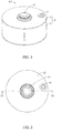
FIG. 1 is a schematic structural diagram of a battery according to an embodiment of this application; -
FIG. 2 is a top view of the battery shown inFIG. 1 ; -
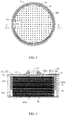
FIG. 3 is a top view of the battery shown inFIG. 1 after a second housing is removed; -
FIG. 4 is a cross-sectional view of the battery shown inFIG. 2 along an IV-IV direction according to an embodiment of this application; -
FIG. 5 is a cross-sectional view of a composite plate of the battery shown inFIG. 4 according to an embodiment of this application; -
FIG. 6 is a cross-sectional view of a composite plate of the battery shown inFIG. 4 according to another embodiment of this application; -
FIG. 7 is a cross-sectional view of a composite plate of the battery shown inFIG. 4 according to still another embodiment of this application; and -
FIG. 8 is a cross-sectional view of the battery shown inFIG. 2 along an IV-IV direction according to another embodiment of this application. -
Housing 10 First housing body 11 Second housing body 12 Electrode pole 13 Injection plug 14 Battery cell 20 First end 20a Second end 20b Lateral surface 20c First electrode plate 21 Second electrode plate 22 Composite plate 30 First elastic layer 31 Insulation layer 32 Second elastic layer 33 Adhesive layer 34 Battery 100, 200 Gap 101 First tab 210 First connector adapter 211 Second tab 220 Second connector adapter 221 Via hole 300 - This application is further described below with reference to the following specific embodiments and the foregoing drawings.
- The following clearly and fully describes the technical solutions in the embodiments of this application with reference to the drawings hereof. Apparently, the described embodiments are merely a part of but not all of the embodiments of this application. All other embodiments derived by a person of ordinary skill in the art based on the embodiments of this application without making any creative efforts shall fall within the protection scope of this application.
- Unless otherwise defined, all technical and scientific terms used herein have the same meanings as usually understood by a person skilled in the technical field of this application. The terms used in the specification of this application herein are merely intended for describing specific embodiments but are not intended to limit this application.
- The following describes some embodiments of this application in detail with reference to drawings. To the extent that no conflict occurs, the following embodiments and the features in the embodiments may be combined with each other.
- Referring to
FIG. 1 to FIG. 4 , an embodiment of this application provides abattery 100, including ahousing 10 and abattery cell 20 accommodated in thehousing 10. A gap 101 exists between thehousing 10 and thebattery cell 20. Thebattery 100 further includes acomposite plate 30. Thecomposite plate 30 is located in the gap 101. Referring toFIG. 5 , thecomposite plate 30 includes a firstelastic layer 31 and aninsulation layer 32 located on a surface of the firstelastic layer 31. - In this application, the
composite plate 30 is disposed in the gap 101 between thehousing 10 and thebattery cell 20. Thecomposite plate 30 prevents thebattery cell 20 from shaking in thehousing 10, avoids failure of thebattery cell 20 caused by pulling of the tabs in a process of shaking thebattery cell 20, and also avoids short circuits caused by displacement of the electrode plate in the process of pulling the tabs, and improves safety performance and service life of thebattery 100. In addition, the firstelastic layer 31 is elastic. Therefore, the firstelastic layer 31 can be compressed when thebattery cell 20 expands during cycles, thereby releasing a space, compensating for volume loss of thebattery cell 20 caused by the use of thecomposite plate 30, and increasing the energy density of thebattery 100. - In an embodiment, the
insulation layer 32 is located between the firstelastic layer 31 and thebattery cell 20. Theinsulation layer 20 is configured to electrically isolate thebattery cell 20. - In another embodiment, the first
elastic layer 31 includes an insulation material. In this case, the firstelastic layer 31 may also be located between theinsulation layer 32 and thebattery cell 20. Specifically, the insulation material of the firstelastic layer 31 may include at least one of expandable polyethylene (EPE), polyurethane (PU), ethylene-vinyl acetate copolymer (EVA), microporous polyurethane, chemically cross-linked polyethylene foamed cotton (IXPE), expandable polypropylene (EPP), polyamide (PA), rubber, or silicone. - A material of the
insulation layer 32 may include at least one of polypropylene (PP), polyethylene terephthalate (PET), polystyrene (PS), polyethylene (PE), polyvinyl chloride (PVC), polyimide (PI), acrylonitrile-butadiene-styrene copolymer (ABS), polycarbonate (PC), polyamide (PA), or polytetrafluoroethylene (PTFE). - The first
elastic layer 31 and theinsulation layer 32 may be combined into one by means of gluing, heat sealing, welding, and the like. - In an embodiment, a width of the first
elastic layer 31 and/or theinsulation layer 32 is less than or equal to 1,000 mm, and a thickness thereof is less than or equal to 100 mm. The first elastic layer and the second insulation layer extend along two parallel planes respectively. The width is a width of the firstelastic layer 31 or theinsulation layer 32 in any direction on a plane in which the firstelastic layer 31 or theinsulation layer 32 is located. The thickness is a thickness of the firstelastic layer 31 or theinsulation layer 32 in a direction perpendicular to the plane in which the firstelastic layer 31 or theinsulation layer 32 is located. - Referring to
FIG. 3 andFIG. 5 , in an embodiment, thecomposite plate 30 is provided with a viahole 300. The viahole 300 runs through the firstelastic layer 31 and theinsulation layer 32. Therefore, when an electrolytic solution is injected into thehousing 10, the electrolytic solution can pass through the viahole 300 and fully infiltrate thebattery cell 20. This increases a capability of the electrolytic solution to permeate the electrode plate of thebattery cell 20, and ensures a good contact interface between the electrode plate and the electrolytic solution. - The via
hole 300 may be formed by stamping or mechanical cutting or by other means. The viahole 300 may be circular, square, elliptical, triangular, polygonal, or another shape. - As shown in
FIG. 4 , in an embodiment, thebattery cell 20 is a stacked battery cell. The stacked battery cell includes a first end 20a, asecond end 20b disposed opposite to the first end 20a, and alateral surface 20c connected between the first end 20a and thesecond end 20b. Afirst tab 210 is disposed on thebattery cell 20. Thefirst tab 210 protrudes from thelateral surface 20c. Thecomposite plate 30 is located between thehousing 10 and the first end 20a or between thehousing 10 and thesecond end 20b. Therefore, thecomposite plate 30 can prevent thebattery cell 20 from shaking in the gap 101 between the end and thehousing 10. - As shown in
FIG. 4 , onecomposite plate 30 is located between the first end 20a and thehousing 10, and anothercomposite plate 30 is located between thesecond end 20b and thehousing 10. In this case, by stamping or mechanical cutting, thecomposite plate 30 may be processed into a desired shape, such as a circle, a square, an ellipse, a triangle, or a polygon. - Further, the
composite plate 30 may also be located between thehousing 10 and thelateral surface 20c. Therefore, thecomposite plate 30 can prevent thebattery cell 20 from shaking in the gap 101 between thelateral surface 20c and thehousing 10. In this case, thecomposite plate 30 may be in a ring shape, so that thecomposite plate 30 can surround the entirelateral surface 20c of thebattery cell 20 to achieve a good shockproof effect. - When the
composite plate 30 is located between thelateral surface 20c and thehousing 10 and also located between the first end 20a and thehousing 10 and between thesecond end 20b and thehousing 10, thecomposite plate 30 can surround all surfaces of thebattery cell 20 to further improve the shockproof effect of thecomposite plate 30. - As shown in
FIG. 6 , in another embodiment, thecomposite plate 30 further includes a secondelastic layer 33. Theinsulation layer 32 is located between the firstelastic layer 31 and the secondelastic layer 33. An overall thickness of thecomposite plate 30 increases due to the added secondelastic layer 33 and loses a part of volume of thebattery cell 20. However, the secondelastic layer 33 can be configured to be compressed when thebattery cell 20 expands during cycles, thereby releasing a space, and compensating for volume loss of thebattery cell 20 caused by the use of thecomposite plate 30. - As shown in
FIG. 7 , in another embodiment, thecomposite plate 30 further includes anadhesive layer 34. Theadhesive layer 34 is located between the secondelastic layer 33 and theinsulation layer 32. Theadhesive layer 34 is configured to improve a connection strength between the secondelastic layer 33 and theinsulation layer 32. In other embodiments, the adhesive layer may be further disposed between the firstelastic layer 31 and theinsulation layer 32. - As shown in
FIG. 1 andFIG. 4 , in an embodiment, thehousing 10 includes afirst housing body 11 and asecond housing body 12 welded and connected to thefirst housing body 11. Anelectrode pole 13 is disposed on thesecond housing body 12. Theelectrode pole 13 is electrically isolated from thesecond housing body 12. Thefirst tab 210 is electrically connected to theelectrode pole 13. - In this case, the first end 20a is disposed toward the
electrode pole 13. Therefore, when thecomposite plate 30 is located between the first end 20a and thehousing 10, thecomposite plate 30 can also be configured to prevent thebattery cell 20 from directly contacting theelectrode pole 13, prevent the electrode pole on the housing from penetrating the electrode plate of thebattery cell 20 during a crush test, and thereby avoid short circuits. - As shown in
FIG. 4 , thebattery cell 20 further includes asecond tab 220. Thesecond tab 220 protrudes from thelateral surface 20c. Thesecond tab 220 is electrically connected to thefirst housing body 11 or thesecond housing body 12. - By electrically connecting the
first tab 210 to theelectrode pole 13, theelectrode pole 13 can exhibit an electrical polarity identical to that of thefirst electrode plate 21. By electrically connecting thesecond tab 220 to thefirst housing body 11 or thesecond housing body 12, theentire housing 10 can exhibit an electrical polarity identical to that of thesecond electrode plate 22. Theinsulation layer 32 in thecomposite plate 30 is electrically insulative. Therefore, thecomposite plate 30 can also prevent thehousing 10 from directly contacting an electrode plate of an opposite polarity in thebattery cell 20, thereby avoiding short circuits. - Specifically, as shown in
FIG. 4 , thebattery cell 20 includes afirst electrode plate 21, asecond electrode plate 22, and a separator (not shown in the drawing) located between thefirst electrode plate 21 and thesecond electrode plate 22. Thefirst electrode plate 21, the separator, and thesecond electrode plate 22 are stacked to form thebattery cell 20. Thefirst electrode plate 21 includes a first current collector and a first active material layer disposed on a surface of the first current collector. Thefirst tab 210 may be electrically connected to the first active material layer by welding, and electrically connected to theelectrode pole 13 through afirst connector adapter 211. Thesecond tab 220 includes a second current collector and a second active material layer disposed on a surface of the second current collector. Thesecond tab 220 may be electrically connected to the second current collector by welding, and electrically connected to thefirst housing body 11 or thesecond housing body 12 through a second connector adapter 221. - Therefore, when the
first electrode plate 21 is a negative electrode plate, theelectrode pole 13 can exhibit a negative polarity. When thesecond electrode plate 22 is a positive electrode plate, theentire housing 10 can exhibit a positive polarity. - As shown in
FIG. 4 , thefirst housing body 11 contains an accommodation space that is used to accommodate thebattery cell 20. Thesecond housing body 12 is connected to thefirst housing body 11 to close the accommodation space. That is, thesecond housing body 12 is a top cover of thehousing 10. A material of thefirst housing body 11 and thesecond housing body 12 may be metal. For example, the material of thefirst housing body 11 and thesecond housing body 12 may be a steel alloy, an aluminum alloy, an iron alloy, a copper alloy, a nickel alloy, or the like. - As shown in
FIG. 1 to FIG. 4 , thebattery 100 in this embodiment is a button battery, and the material of both thefirst housing body 11 and thesecond housing body 12 is stainless steel. When being prepared, thefirst housing body 11 and thesecond housing body 12 may form a desired shape by using techniques such as laser cutting and machine processing. Thefirst housing body 11 may also form a stamped pit (that is, the accommodation space) by stamping. - As shown in
FIG. 1 , in this embodiment, thesecond housing body 12 is provided with an injection hole (not shown in the drawing). An electrolytic solution can be injected through the injection hole. An injection plug 14 is disposed in the injection hole. The injection plug 14 is configured to seal the injection hole to prevent the injected electrolytic solution from leaking and prevent external impurities from entering the battery. Alternatively, the injection hole may be located on thefirst housing body 11. - Referring to
FIG. 8 , another embodiment of this application further provides abattery 200. A difference from thebattery 100 described above is that abattery cell 20 of thebattery 200 is a wound battery cell. To be specific, thefirst electrode plate 21, the separator, and thesecond electrode plate 22 are wound to form thebattery cell 20. - In this case, the
housing 10 may be provided with no electrode pole. Thefirst housing body 11 and thesecond housing body 12 are fixed by a sealing ring (not shown in the drawing). To be specific, thefirst housing body 11 and thesecond housing body 12 are electrically isolated by the sealing ring. Thefirst tab 210 is electrically connected to thesecond housing body 12, and thesecond tab 220 is electrically connected to thefirst housing body 11. - The foregoing descriptions are merely exemplary embodiments of this application, but are not intended to limit this application. Any modifications, equivalent substitutions, and improvements made without departing from the spirit and principles of this application shall fall within the protection scope of this application.
Claims (10)
- A battery (100), comprising: a housing (10) and a battery cell (20) accommodated in the housing (10), with a gap (101) existing between the housing (10) and the battery cell (20), characterized in that the battery (100) further comprises:a composite plate (30), wherein the composite plate (30) is located in the gap (101), andthe composite plate (30) comprises a first elastic layer (31) and an insulation layer (32) located on a surface of the first elastic layer (31).
- The battery (100) according to claim 1, characterized in that the insulation layer (32) is located between the first elastic layer (31) and the battery cell (20).
- The battery (100) according to claim 1 or 2, characterized in that the first elastic layer (31) comprises an insulation material, and the first elastic layer (31) is located between the insulation layer (32) and the battery cell (20).
- The battery (100) according to claim 3, characterized in that the insulation material of the first elastic layer (31) comprises at least one of expandable polyethylene, polyurethane, ethylene-vinyl acetate copolymer, microporous polyurethane, chemically cross-linked polyethylene foamed cotton, expandable polypropylene, polyamide, rubber, or silicone.
- The battery (100) according to any one of claims 1 to 4, characterized in that a width of the first elastic layer (31) and/or the insulation layer (32) is less than or equal to 1,000 mm, and a thickness thereof is less than or equal to 100 mm.
- The battery (100) according to any one of claims 1 to 5, characterized in that the composite plate (30) is provided with a via hole (300), and the via hole (300) runs through the first elastic layer (31) and the insulation layer (32).
- The battery (100) according to any one of claims 1 to 6, characterized in that the battery cell (20) is a stacked battery cell; the stacked battery cell comprises a first end (20a), a second end (20b) disposed opposite to the first end (20a), and a lateral surface (20c) connected between the first end (20a) and the second end (20b); a first tab (210) is disposed on the battery cell (20), and the first tab (210) protrudes from the lateral surface (20c); and the composite plate (30) is located between the housing (10) and the first end (20a), or between the housing (10) and the second end (20b), or between the housing (10) and the lateral surface (20c).
- The battery (100) according to any one of claims 1 to 7, characterized in that the composite plate (30) further comprises a second elastic layer (33), and the insulation layer (32) is located between the first elastic layer (31) and the second elastic layer (33).
- The battery (100) according to claim 8, characterized in that the composite plate (30) further comprises an adhesive layer (34), and the adhesive layer (34) is located between the second elastic layer (33) and the insulation layer (32).
- The battery (100) according to any one of claims 1 to 9, characterized in that the housing (10) comprises a first housing body (11) and a second housing body (12) welded and connected to the first housing body (11), and an electrode pole (13) is disposed on the second housing body (12), and the electrode pole (13) is electrically isolated from the second housing body (12); and
a first tab (210) and a second tab (220) are disposed on the battery cell (20), the first tab (210) is electrically connected to the electrode pole (13), and the second tab (220) is electrically connected to the first housing body (11) or the second housing body (12).
Applications Claiming Priority (1)
| Application Number | Priority Date | Filing Date | Title |
|---|---|---|---|
| CN202021100961.7U CN212848600U (en) | 2020-06-15 | 2020-06-15 | Battery |
Publications (2)
| Publication Number | Publication Date |
|---|---|
| EP3926738A1 true EP3926738A1 (en) | 2021-12-22 |
| EP3926738B1 EP3926738B1 (en) | 2026-04-22 |
Family
ID=75173917
Family Applications (1)
| Application Number | Title | Priority Date | Filing Date |
|---|---|---|---|
| EP21164293.9A Active EP3926738B1 (en) | 2020-06-15 | 2021-03-23 | Battery |
Country Status (2)
| Country | Link |
|---|---|
| EP (1) | EP3926738B1 (en) |
| CN (1) | CN212848600U (en) |
Families Citing this family (2)
| Publication number | Priority date | Publication date | Assignee | Title |
|---|---|---|---|---|
| WO2022205140A1 (en) * | 2021-03-31 | 2022-10-06 | 宁德新能源科技有限公司 | Battery and electric device |
| CN114649651B (en) * | 2022-03-04 | 2024-06-14 | 广东维都利新能源有限公司 | Electrodeless lug welded battery and preparation method thereof |
Citations (3)
| Publication number | Priority date | Publication date | Assignee | Title |
|---|---|---|---|---|
| US20130078503A1 (en) * | 2011-09-26 | 2013-03-28 | Dae-Kyu Kim | Rechargeable battery |
| US20180261805A1 (en) * | 2017-03-10 | 2018-09-13 | Evolution Engineering Inc. | Battery coil engaging members for downhole tools |
| CN110190340A (en) * | 2019-03-01 | 2019-08-30 | 青海时代新能源科技有限公司 | Secondary cell |
-
2020
- 2020-06-15 CN CN202021100961.7U patent/CN212848600U/en active Active
-
2021
- 2021-03-23 EP EP21164293.9A patent/EP3926738B1/en active Active
Patent Citations (3)
| Publication number | Priority date | Publication date | Assignee | Title |
|---|---|---|---|---|
| US20130078503A1 (en) * | 2011-09-26 | 2013-03-28 | Dae-Kyu Kim | Rechargeable battery |
| US20180261805A1 (en) * | 2017-03-10 | 2018-09-13 | Evolution Engineering Inc. | Battery coil engaging members for downhole tools |
| CN110190340A (en) * | 2019-03-01 | 2019-08-30 | 青海时代新能源科技有限公司 | Secondary cell |
Also Published As
| Publication number | Publication date |
|---|---|
| CN212848600U (en) | 2021-03-30 |
| EP3926738B1 (en) | 2026-04-22 |
Similar Documents
| Publication | Publication Date | Title |
|---|---|---|
| KR101285745B1 (en) | Jelly-Roll of Improved Structure and Secondary Battery Comprising the Same | |
| EP3451416B1 (en) | Second battery | |
| EP3671902B1 (en) | Battery module having bus bar assembly | |
| JP4092060B2 (en) | Secondary battery | |
| JP5363404B2 (en) | Secondary battery | |
| JP6574084B2 (en) | Secondary battery | |
| EP2999029B1 (en) | Electrode assembly and secondary battery including the same | |
| US9853294B2 (en) | Secondary battery and manufacturing method thereof | |
| US20140141293A1 (en) | Prismatic storage battery | |
| EP3886239A1 (en) | Battery and powered apparatus provided with battery | |
| KR20110128051A (en) | Secondary battery | |
| WO2023241234A1 (en) | Electrochemical device and electric apparatus | |
| US20250316802A1 (en) | All-solid-state battery | |
| EP4167354A1 (en) | Secondary battery | |
| JP2009087613A (en) | Square battery | |
| EP2978061B1 (en) | Pouch-type secondary battery and secondary battery module comprising same | |
| EP3926738B1 (en) | Battery | |
| US20230120508A1 (en) | Battery and electric apparatus having such battery | |
| KR20160046477A (en) | Battery cell, and battery module | |
| US10135057B2 (en) | Electrode assembly and secondary battery having the same | |
| JP2016207286A (en) | Electrodes and batteries | |
| JP2016091859A (en) | battery | |
| US20240030521A1 (en) | Battery and electric device | |
| JP6943832B2 (en) | Fixtures and battery modules | |
| KR101849757B1 (en) | Secondary Battery Including an Electrode Lead Made of a Combination of Metal Layers Having Different Resistance Values |
Legal Events
| Date | Code | Title | Description |
|---|---|---|---|
| PUAI | Public reference made under article 153(3) epc to a published international application that has entered the european phase |
Free format text: ORIGINAL CODE: 0009012 |
|
| STAA | Information on the status of an ep patent application or granted ep patent |
Free format text: STATUS: REQUEST FOR EXAMINATION WAS MADE |
|
| 17P | Request for examination filed |
Effective date: 20210323 |
|
| AK | Designated contracting states |
Kind code of ref document: A1 Designated state(s): AL AT BE BG CH CY CZ DE DK EE ES FI FR GB GR HR HU IE IS IT LI LT LU LV MC MK MT NL NO PL PT RO RS SE SI SK SM TR |
|
| B565 | Issuance of search results under rule 164(2) epc |
Effective date: 20210923 |
|
| GRAP | Despatch of communication of intention to grant a patent |
Free format text: ORIGINAL CODE: EPIDOSNIGR1 |
|
| STAA | Information on the status of an ep patent application or granted ep patent |
Free format text: STATUS: GRANT OF PATENT IS INTENDED |
|
| INTG | Intention to grant announced |
Effective date: 20251113 |
|
| GRAS | Grant fee paid |
Free format text: ORIGINAL CODE: EPIDOSNIGR3 |
|
| GRAA | (expected) grant |
Free format text: ORIGINAL CODE: 0009210 |
|
| STAA | Information on the status of an ep patent application or granted ep patent |
Free format text: STATUS: THE PATENT HAS BEEN GRANTED |
|
| P01 | Opt-out of the competence of the unified patent court (upc) registered |
Free format text: CASE NUMBER: UPC_APP_0006295_3926738/2026 Effective date: 20260220 |
|
| AK | Designated contracting states |
Kind code of ref document: B1 Designated state(s): AL AT BE BG CH CY CZ DE DK EE ES FI FR GB GR HR HU IE IS IT LI LT LU LV MC MK MT NL NO PL PT RO RS SE SI SK SM TR |
|
| REG | Reference to a national code |
Ref country code: CH Ref legal event code: F10 Free format text: ST27 STATUS EVENT CODE: U-0-0-F10-F00 (AS PROVIDED BY THE NATIONAL OFFICE) Effective date: 20260422 Ref country code: GB Ref legal event code: FG4D |
|
| REG | Reference to a national code |
Ref country code: DE Ref legal event code: R096 Ref document number: 602021052421 Country of ref document: DE |