EP3926731A1 - Battery rack and power storage device comprising same - Google Patents
Battery rack and power storage device comprising same Download PDFInfo
- Publication number
- EP3926731A1 EP3926731A1 EP20863209.1A EP20863209A EP3926731A1 EP 3926731 A1 EP3926731 A1 EP 3926731A1 EP 20863209 A EP20863209 A EP 20863209A EP 3926731 A1 EP3926731 A1 EP 3926731A1
- Authority
- EP
- European Patent Office
- Prior art keywords
- battery
- battery module
- module assembly
- rack
- modules
- Prior art date
- Legal status (The legal status is an assumption and is not a legal conclusion. Google has not performed a legal analysis and makes no representation as to the accuracy of the status listed.)
- Pending
Links
Images





Classifications
-
- H—ELECTRICITY
- H01—ELECTRIC ELEMENTS
- H01M—PROCESSES OR MEANS, e.g. BATTERIES, FOR THE DIRECT CONVERSION OF CHEMICAL ENERGY INTO ELECTRICAL ENERGY
- H01M50/00—Constructional details or processes of manufacture of the non-active parts of electrochemical cells other than fuel cells, e.g. hybrid cells
- H01M50/20—Mountings; Secondary casings or frames; Racks, modules or packs; Suspension devices; Shock absorbers; Transport or carrying devices; Holders
-
- H—ELECTRICITY
- H01—ELECTRIC ELEMENTS
- H01M—PROCESSES OR MEANS, e.g. BATTERIES, FOR THE DIRECT CONVERSION OF CHEMICAL ENERGY INTO ELECTRICAL ENERGY
- H01M50/00—Constructional details or processes of manufacture of the non-active parts of electrochemical cells other than fuel cells, e.g. hybrid cells
- H01M50/20—Mountings; Secondary casings or frames; Racks, modules or packs; Suspension devices; Shock absorbers; Transport or carrying devices; Holders
- H01M50/204—Racks, modules or packs for multiple batteries or multiple cells
-
- H—ELECTRICITY
- H01—ELECTRIC ELEMENTS
- H01M—PROCESSES OR MEANS, e.g. BATTERIES, FOR THE DIRECT CONVERSION OF CHEMICAL ENERGY INTO ELECTRICAL ENERGY
- H01M10/00—Secondary cells; Manufacture thereof
- H01M10/42—Methods or arrangements for servicing or maintenance of secondary cells or secondary half-cells
-
- H—ELECTRICITY
- H01—ELECTRIC ELEMENTS
- H01M—PROCESSES OR MEANS, e.g. BATTERIES, FOR THE DIRECT CONVERSION OF CHEMICAL ENERGY INTO ELECTRICAL ENERGY
- H01M10/00—Secondary cells; Manufacture thereof
- H01M10/42—Methods or arrangements for servicing or maintenance of secondary cells or secondary half-cells
- H01M10/425—Structural combination with electronic components, e.g. electronic circuits integrated to the outside of the casing
-
- H—ELECTRICITY
- H01—ELECTRIC ELEMENTS
- H01M—PROCESSES OR MEANS, e.g. BATTERIES, FOR THE DIRECT CONVERSION OF CHEMICAL ENERGY INTO ELECTRICAL ENERGY
- H01M10/00—Secondary cells; Manufacture thereof
- H01M10/42—Methods or arrangements for servicing or maintenance of secondary cells or secondary half-cells
- H01M10/44—Methods for charging or discharging
- H01M10/441—Methods for charging or discharging for several batteries or cells simultaneously or sequentially
-
- H—ELECTRICITY
- H01—ELECTRIC ELEMENTS
- H01M—PROCESSES OR MEANS, e.g. BATTERIES, FOR THE DIRECT CONVERSION OF CHEMICAL ENERGY INTO ELECTRICAL ENERGY
- H01M10/00—Secondary cells; Manufacture thereof
- H01M10/60—Heating or cooling; Temperature control
- H01M10/61—Types of temperature control
- H01M10/613—Cooling or keeping cold
-
- H—ELECTRICITY
- H01—ELECTRIC ELEMENTS
- H01M—PROCESSES OR MEANS, e.g. BATTERIES, FOR THE DIRECT CONVERSION OF CHEMICAL ENERGY INTO ELECTRICAL ENERGY
- H01M10/00—Secondary cells; Manufacture thereof
- H01M10/60—Heating or cooling; Temperature control
- H01M10/62—Heating or cooling; Temperature control specially adapted for specific applications
- H01M10/627—Stationary installations, e.g. power plant buffering or backup power supplies
-
- H—ELECTRICITY
- H01—ELECTRIC ELEMENTS
- H01M—PROCESSES OR MEANS, e.g. BATTERIES, FOR THE DIRECT CONVERSION OF CHEMICAL ENERGY INTO ELECTRICAL ENERGY
- H01M10/00—Secondary cells; Manufacture thereof
- H01M10/60—Heating or cooling; Temperature control
- H01M10/65—Means for temperature control structurally associated with the cells
- H01M10/656—Means for temperature control structurally associated with the cells characterised by the type of heat-exchange fluid
- H01M10/6561—Gases
- H01M10/6563—Gases with forced flow, e.g. by blowers
-
- H—ELECTRICITY
- H01—ELECTRIC ELEMENTS
- H01M—PROCESSES OR MEANS, e.g. BATTERIES, FOR THE DIRECT CONVERSION OF CHEMICAL ENERGY INTO ELECTRICAL ENERGY
- H01M50/00—Constructional details or processes of manufacture of the non-active parts of electrochemical cells other than fuel cells, e.g. hybrid cells
- H01M50/10—Primary casings; Jackets or wrappings
- H01M50/102—Primary casings; Jackets or wrappings characterised by their shape or physical structure
- H01M50/103—Primary casings; Jackets or wrappings characterised by their shape or physical structure prismatic or rectangular
-
- H—ELECTRICITY
- H01—ELECTRIC ELEMENTS
- H01M—PROCESSES OR MEANS, e.g. BATTERIES, FOR THE DIRECT CONVERSION OF CHEMICAL ENERGY INTO ELECTRICAL ENERGY
- H01M50/00—Constructional details or processes of manufacture of the non-active parts of electrochemical cells other than fuel cells, e.g. hybrid cells
- H01M50/20—Mountings; Secondary casings or frames; Racks, modules or packs; Suspension devices; Shock absorbers; Transport or carrying devices; Holders
- H01M50/204—Racks, modules or packs for multiple batteries or multiple cells
- H01M50/207—Racks, modules or packs for multiple batteries or multiple cells characterised by their shape
- H01M50/209—Racks, modules or packs for multiple batteries or multiple cells characterised by their shape adapted for prismatic or rectangular cells
-
- H—ELECTRICITY
- H01—ELECTRIC ELEMENTS
- H01M—PROCESSES OR MEANS, e.g. BATTERIES, FOR THE DIRECT CONVERSION OF CHEMICAL ENERGY INTO ELECTRICAL ENERGY
- H01M50/00—Constructional details or processes of manufacture of the non-active parts of electrochemical cells other than fuel cells, e.g. hybrid cells
- H01M50/20—Mountings; Secondary casings or frames; Racks, modules or packs; Suspension devices; Shock absorbers; Transport or carrying devices; Holders
- H01M50/251—Mountings; Secondary casings or frames; Racks, modules or packs; Suspension devices; Shock absorbers; Transport or carrying devices; Holders specially adapted for stationary devices, e.g. power plant buffering or backup power supplies
-
- H—ELECTRICITY
- H01—ELECTRIC ELEMENTS
- H01M—PROCESSES OR MEANS, e.g. BATTERIES, FOR THE DIRECT CONVERSION OF CHEMICAL ENERGY INTO ELECTRICAL ENERGY
- H01M50/00—Constructional details or processes of manufacture of the non-active parts of electrochemical cells other than fuel cells, e.g. hybrid cells
- H01M50/20—Mountings; Secondary casings or frames; Racks, modules or packs; Suspension devices; Shock absorbers; Transport or carrying devices; Holders
- H01M50/258—Modular batteries; Casings provided with means for assembling
-
- H—ELECTRICITY
- H01—ELECTRIC ELEMENTS
- H01M—PROCESSES OR MEANS, e.g. BATTERIES, FOR THE DIRECT CONVERSION OF CHEMICAL ENERGY INTO ELECTRICAL ENERGY
- H01M50/00—Constructional details or processes of manufacture of the non-active parts of electrochemical cells other than fuel cells, e.g. hybrid cells
- H01M50/20—Mountings; Secondary casings or frames; Racks, modules or packs; Suspension devices; Shock absorbers; Transport or carrying devices; Holders
- H01M50/296—Mountings; Secondary casings or frames; Racks, modules or packs; Suspension devices; Shock absorbers; Transport or carrying devices; Holders characterised by terminals of battery packs
-
- H—ELECTRICITY
- H01—ELECTRIC ELEMENTS
- H01M—PROCESSES OR MEANS, e.g. BATTERIES, FOR THE DIRECT CONVERSION OF CHEMICAL ENERGY INTO ELECTRICAL ENERGY
- H01M50/00—Constructional details or processes of manufacture of the non-active parts of electrochemical cells other than fuel cells, e.g. hybrid cells
- H01M50/50—Current conducting connections for cells or batteries
- H01M50/502—Interconnectors for connecting terminals of adjacent batteries; Interconnectors for connecting cells outside a battery casing
- H01M50/503—Interconnectors for connecting terminals of adjacent batteries; Interconnectors for connecting cells outside a battery casing characterised by the shape of the interconnectors
-
- H—ELECTRICITY
- H01—ELECTRIC ELEMENTS
- H01M—PROCESSES OR MEANS, e.g. BATTERIES, FOR THE DIRECT CONVERSION OF CHEMICAL ENERGY INTO ELECTRICAL ENERGY
- H01M50/00—Constructional details or processes of manufacture of the non-active parts of electrochemical cells other than fuel cells, e.g. hybrid cells
- H01M50/50—Current conducting connections for cells or batteries
- H01M50/502—Interconnectors for connecting terminals of adjacent batteries; Interconnectors for connecting cells outside a battery casing
- H01M50/507—Interconnectors for connecting terminals of adjacent batteries; Interconnectors for connecting cells outside a battery casing comprising an arrangement of two or more busbars within a container structure, e.g. busbar modules
-
- H—ELECTRICITY
- H01—ELECTRIC ELEMENTS
- H01M—PROCESSES OR MEANS, e.g. BATTERIES, FOR THE DIRECT CONVERSION OF CHEMICAL ENERGY INTO ELECTRICAL ENERGY
- H01M50/00—Constructional details or processes of manufacture of the non-active parts of electrochemical cells other than fuel cells, e.g. hybrid cells
- H01M50/50—Current conducting connections for cells or batteries
- H01M50/502—Interconnectors for connecting terminals of adjacent batteries; Interconnectors for connecting cells outside a battery casing
- H01M50/509—Interconnectors for connecting terminals of adjacent batteries; Interconnectors for connecting cells outside a battery casing characterised by the type of connection, e.g. mixed connections
- H01M50/51—Connection only in series
-
- H—ELECTRICITY
- H01—ELECTRIC ELEMENTS
- H01M—PROCESSES OR MEANS, e.g. BATTERIES, FOR THE DIRECT CONVERSION OF CHEMICAL ENERGY INTO ELECTRICAL ENERGY
- H01M50/00—Constructional details or processes of manufacture of the non-active parts of electrochemical cells other than fuel cells, e.g. hybrid cells
- H01M50/50—Current conducting connections for cells or batteries
- H01M50/572—Means for preventing undesired use or discharge
-
- H—ELECTRICITY
- H01—ELECTRIC ELEMENTS
- H01M—PROCESSES OR MEANS, e.g. BATTERIES, FOR THE DIRECT CONVERSION OF CHEMICAL ENERGY INTO ELECTRICAL ENERGY
- H01M10/00—Secondary cells; Manufacture thereof
- H01M10/42—Methods or arrangements for servicing or maintenance of secondary cells or secondary half-cells
- H01M10/425—Structural combination with electronic components, e.g. electronic circuits integrated to the outside of the casing
- H01M2010/4271—Battery management systems including electronic circuits, e.g. control of current or voltage to keep battery in healthy state, cell balancing
-
- H—ELECTRICITY
- H01—ELECTRIC ELEMENTS
- H01M—PROCESSES OR MEANS, e.g. BATTERIES, FOR THE DIRECT CONVERSION OF CHEMICAL ENERGY INTO ELECTRICAL ENERGY
- H01M10/00—Secondary cells; Manufacture thereof
- H01M10/42—Methods or arrangements for servicing or maintenance of secondary cells or secondary half-cells
- H01M10/425—Structural combination with electronic components, e.g. electronic circuits integrated to the outside of the casing
- H01M2010/4278—Systems for data transfer from batteries, e.g. transfer of battery parameters to a controller, data transferred between battery controller and main controller
-
- H—ELECTRICITY
- H01—ELECTRIC ELEMENTS
- H01M—PROCESSES OR MEANS, e.g. BATTERIES, FOR THE DIRECT CONVERSION OF CHEMICAL ENERGY INTO ELECTRICAL ENERGY
- H01M2220/00—Batteries for particular applications
- H01M2220/10—Batteries in stationary systems, e.g. emergency power source in plant
-
- H—ELECTRICITY
- H01—ELECTRIC ELEMENTS
- H01M—PROCESSES OR MEANS, e.g. BATTERIES, FOR THE DIRECT CONVERSION OF CHEMICAL ENERGY INTO ELECTRICAL ENERGY
- H01M2220/00—Batteries for particular applications
- H01M2220/20—Batteries in motive systems, e.g. vehicle, ship, plane
-
- Y—GENERAL TAGGING OF NEW TECHNOLOGICAL DEVELOPMENTS; GENERAL TAGGING OF CROSS-SECTIONAL TECHNOLOGIES SPANNING OVER SEVERAL SECTIONS OF THE IPC; TECHNICAL SUBJECTS COVERED BY FORMER USPC CROSS-REFERENCE ART COLLECTIONS [XRACs] AND DIGESTS
- Y02—TECHNOLOGIES OR APPLICATIONS FOR MITIGATION OR ADAPTATION AGAINST CLIMATE CHANGE
- Y02E—REDUCTION OF GREENHOUSE GAS [GHG] EMISSIONS, RELATED TO ENERGY GENERATION, TRANSMISSION OR DISTRIBUTION
- Y02E60/00—Enabling technologies; Technologies with a potential or indirect contribution to GHG emissions mitigation
- Y02E60/10—Energy storage using batteries
-
- Y—GENERAL TAGGING OF NEW TECHNOLOGICAL DEVELOPMENTS; GENERAL TAGGING OF CROSS-SECTIONAL TECHNOLOGIES SPANNING OVER SEVERAL SECTIONS OF THE IPC; TECHNICAL SUBJECTS COVERED BY FORMER USPC CROSS-REFERENCE ART COLLECTIONS [XRACs] AND DIGESTS
- Y02—TECHNOLOGIES OR APPLICATIONS FOR MITIGATION OR ADAPTATION AGAINST CLIMATE CHANGE
- Y02P—CLIMATE CHANGE MITIGATION TECHNOLOGIES IN THE PRODUCTION OR PROCESSING OF GOODS
- Y02P70/00—Climate change mitigation technologies in the production process for final industrial or consumer products
- Y02P70/50—Manufacturing or production processes characterised by the final manufactured product
Definitions
- the present disclosure relates to a battery rack and an energy storage system including the battery rack.
- Secondary batteries which are highly applicable to various products and exhibit superior electrical properties such as high energy density, etc. are commonly used not only in portable devices but also in electric vehicles (EVs) or hybrid electric vehicles (HEVs) driven by electrical power sources.
- EVs electric vehicles
- HEVs hybrid electric vehicles
- the secondary battery is drawing attentions as a new energy source for enhancing environment friendliness and energy efficiency in that the use of fossil fuels can be reduced greatly and no byproduct is generated during energy consumption.
- Secondary batteries widely used at present include lithium ion batteries, lithium polymer batteries, nickel cadmium batteries, nickel hydrogen batteries, nickel zinc batteries and the like.
- An operating voltage of the unit secondary battery cell namely a unit battery cell, is about 2.5V to 4.5V. Therefore, if a higher output voltage is required, a plurality of battery cells may be connected in series to configure a battery pack. In addition, depending on the charge/discharge capacity required for the battery pack, a plurality of battery cells may be connected in parallel to configure a battery pack. Thus, the number of battery cells included in the battery pack may be variously set according to the required output voltage or the demanded charge/discharge capacity.
- an energy storage system may be configured to include at least one battery rack that includes at least one battery module.
- the conventional battery rack is configured to include a plurality of battery modules and a rack case for accommodating the plurality of battery modules.
- the plurality of battery modules are generally arranged to be vertically stacked in a line inside the rack case along an upper and lower direction of the rack case, and are electrically connected to each other via a bus bar unit that connects terminals of the battery modules inside the rack case for electrical connection with each other.
- the capacity increase of the battery rack is accelerating according to the request of customers. Accordingly, when the plurality of battery modules are vertically stacked in the rack case, the need for a two-row vertical stacking structure is increasing instead of a one-row structure.
- the present disclosure is directed to providing a battery rack capable of efficiently connecting terminals of battery modules, and an energy storage system including the battery rack.
- the present disclosure is also directed to providing a battery rack capable of reducing manufacturing costs and improving assembly process efficiency, and an energy storage system including the battery rack.
- a battery rack comprising:
- the battery rack may further comprise a bus bar unit configured to electrically connect the plurality of battery modules of the first battery module assembly and the plurality of battery modules of the second battery module assembly.
- the bus bar unit may be provided to have a straight bar shape.
- the bus bar unit may include a plurality of first bus bar members configured to connect the plurality of battery modules of the first battery module assembly to each other; a plurality of second bus bar members configured to connect the plurality of battery modules of the second battery module assembly to each other; and a connection bus bar member configured to connect the first battery module assembly and the second battery module assembly to each other.
- connection bus bar member may be configured to connect a battery module at a bottom end of the first battery module assembly and a battery module at a bottom end of the second battery module assembly to each other.
- connection bus bar member may be provided to have a straight bar shape and configured to connect the battery module at the bottom end of the first battery module assembly and the battery module at the bottom end of the second battery module assembly to each other in a horizontal direction of the rack case.
- Each of the plurality of battery modules may include at least one battery cell; a module case configured to accommodate the at least one battery cell; and a positive electrode terminal and a negative electrode terminal provided at one side of the module case and electrically connected to the at least one battery cell.
- the positive electrode terminal and the negative electrode terminal may be arranged in an upper and lower direction at one end of the module case.
- Each of the plurality of battery modules may include an identifying member provided to the module case and configured to determine whether the battery modules are arranged in a forward direction or a rearward direction based on the upper and lower direction of the rack case.
- each of the plurality of battery modules may include at least two cell assemblies having a plurality of battery cells; and a battery management system configured to control charging and discharging of the plurality of battery cells.
- the battery rack may include a central control unit configured to receive state information of the battery module from the battery management system provided to each of the plurality of battery modules and control charging and discharging of the plurality of battery modules.
- the battery rack may include:
- the fan power cable may include:
- the connector unit of the fan power cable may include:
- the battery rack may further comprise a communication cable configured to provide and receive a communication signal between the central control unit and the battery management system provided to each of the plurality of battery modules.
- the communication cable may include:
- the present disclosure also provides an energy storage system, comprising at least one battery rack according to the above embodiments.
- a battery rack capable of efficiently connecting terminals of battery modules, and an energy storage system including the battery rack.
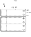
- FIG. 1 is a diagram for illustrating a battery rack according to an embodiment of the present disclosure
- FIG. 2 is a diagram for illustrating a battery module of a first battery module assembly, provided to the battery rack of FIG. 1
- FIG. 3 is a diagram for illustrating a battery module of a second battery module assembly, provided to the battery rack of FIG. 1 .
- a battery rack 10 may include a rack case 100, a first battery module assembly 200, a second battery module assembly 205, and a bus bar unit 300.
- the rack case 100 is configured to accommodate the first battery module assembly 200 and the second battery module assembly 205, explained later, and may have a predetermined accommodation space for this purpose.
- the first battery module assembly 200 is disposed inside the rack case 100, and may include a plurality of battery modules 250.
- the plurality of battery modules 250 may be vertically stacked inside the rack case 100 along an upper and lower direction of the rack case 100.
- Each of the battery modules 250 may include a battery cell 251, a module case 253, a positive electrode terminal 255, and a negative electrode terminal 257.
- the battery cell 251 is a secondary battery and may be provided as a pouch-type secondary battery, a rectangular secondary battery, or a cylindrical secondary battery. Hereinafter, in this embodiment, it will be described that the battery cell 251 is a pouch-type secondary battery.
- At least one battery cell 251 or a plurality of battery cells 251 may be provided.
- the battery cell 251 is provided in plural.
- the module case 253 may accommodate the at least one battery cell 251 or the plurality of battery cells 251. To this end, the accommodation space for accommodating the battery cell 251 may be provided in the module case 253.
- the positive electrode terminal 255 is electrically connected to the at least one battery cell 251 or the plurality of battery cells 251 and may be provided at one side of the module case 253. Specifically, the positive electrode terminal 255 may be disposed at the front of one end of the module case 253.
- the negative electrode terminal 257 is electrically connected to the at least one battery cell 251 or the plurality of battery cells 251 and may be provided at one side of the module case 253. Specifically, the negative electrode terminal 257 may be disposed at the front of one end of the module case 253 and may be arranged in an upper and lower direction with respect to the positive electrode terminal 255 at one end of the module case 253.
- the positive electrode terminal 255 may be disposed above the negative electrode terminal 257.
- the second battery module assembly 205 may be disposed to be spaced apart from the first battery module assembly 200 by a predetermined distance in a horizontal direction.
- the second battery module assembly 205 may include a plurality of battery modules 250 vertically stacked along the upper and lower direction of the rack case 100.
- the second battery module assembly 205 and the first battery module assembly 200 may form a two-row vertical stacking structure inside the rack case 100. Accordingly, the battery rack 10 according to this embodiment may implement a large-capacity battery rack 10 with a higher energy density.
- the plurality of battery modules 250 of the second battery module assembly 205 may also include a battery cell 251, a module case 253, a positive electrode terminal 255, and a negative electrode terminal 257.
- the plurality of battery modules 250 of the second battery module assembly 205 are arranged such that upper and lower portions thereof are inverted based on the arrangement of the plurality of battery modules 250 of the first battery module assembly 200.
- the positive electrode terminal 255 may be disposed under the negative electrode terminal 257.
- the positive electrode terminal 255 may be disposed above the negative electrode terminal 257.
- the plurality of battery modules 250 of the first battery module assembly 200 may be arranged in a forward direction based on the upper and lower direction of the rack case 100
- the plurality of battery modules 250 of the second battery module assembly 205 may be arranged in a rearward direction based on the upper and lower direction of the rack case 100
- the forward direction may refer to a direction in which the positive electrode terminal 255 is disposed above the negative electrode terminal 257 based on the upper and lower direction of the rack case 100
- the rearward direction may refer to a direction in which the positive electrode terminal 255 is disposed below the negative electrode terminal 257 based on the upper and lower direction of the rack case 100.
- the positive electrode terminal 255 and the negative electrode terminal 257 of the plurality of battery modules 250 of the second battery module assembly 205 disposed at the right of the first battery module assembly 200 may be disposed at the front of the left end of the module case 253, and the positive electrode terminal 255 and the negative electrode terminal 257 of the plurality of battery modules 250 of the first battery module assembly 200 may be disposed at the front of the right end of the module case 253, so that their terminals 255, 257 are placed closer to each other.
- the bus bar unit 300 may electrically connect the plurality of battery modules 250 of the first battery module assembly 200 and the plurality of battery modules 250 of the second battery module assembly 205.
- the bus bar unit 300 may include a first bus bar member 310, a second bus bar member 330, and a connection bus bar member 350.
- the first bus bar member 310 is provided to have a straight bar shape elongated in one direction and may be provided in plural.
- the plurality of first bus bar members 310 may connect the plurality of battery modules 250 of the first battery module assembly 200 to each other.
- the second bus bar member 330 is provided to have a straight bar shape elongated in one direction and may be provided in plural, like the first bus bar member 310.
- the plurality of second bus bar members 330 may connect the plurality of battery modules 250 of the second battery module assembly 205 to each other.
- connection bus bar member 350 may be provided to have a straight bar shape elongated in one direction, like the first bus bar member 310 and the second bus bar member 330. That is, in this embodiment, all the first bus bar member 310, the second bus bar member 330 and the connection bus bar member 350 may be provided in a straight bar shape. After all, in this embodiment, the bus bar units 300 may be provided to have the same straight bar shape. In other words, the bus bar units may have a simple shape, rather than a complicatedly bent shape.
- connection bus bar member 350 may connect the first battery module assembly 200 and the second battery module assembly 205 to each other. Specifically, the connection bus bar member 350 may connect a battery module 250 at a bottom end of the first battery module assembly 200 and a battery module 250 at a bottom end of the second battery module assembly 205 to each other. More specifically, the connection bus bar member 350 may connect the negative electrode terminal 257 of the battery module 250 at the bottom end of the first battery module assembly 200 and the positive electrode terminal 255 of the battery module 250 at the bottom end of the second battery module assembly 205 to each other in a horizontal direction of the rack case 100.
- the positive electrode terminal 255 and the negative electrode terminal 257 are formed at the front of the right end of the battery module 250 of the first battery module assembly 200, and the negative electrode terminal 257 and the positive electrode terminal 255 are formed at the front of the left end of the battery module 250 of the second battery module assembly 205. Accordingly, the negative electrode terminal 257 of the battery module 250 of the first battery module assembly 200 may be located close to the positive electrode terminal 255 of the battery module 250 of the second battery module assembly 205.
- the length of the connection bus bar member 350 for connecting the first battery module assembly 200 and the second battery module assembly 205 to each other may be minimized.
- connection bus bar member of the elongated structure not only increases material cost, but also blocks the front of the battery module after installation, which makes a worker using the battery module uncomfortable. Therefore, the battery rack of the present disclosure may greatly reduce the length of the connection bus bar member, thereby reducing the manufacturing cost of the battery rack and greatly increasing the convenience of use.
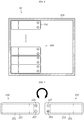
- FIGS. 4 to 8 are diagrams for illustrating a process of assembling the battery rack of FIG. 1 .
- a manufacturer or the like may vertically stack the battery modules 250 of the first battery module assembly 200 in the rack case 100.
- the battery modules 250 of the first battery module assembly 200 may be arranged in a forward direction based on the upper and lower direction of the rack case 100.
- the manufacturer or the like may vertically stack the battery modules 250 of the second battery module assembly 205 in the rack case 100.
- the manufacturer or the like may invert the battery modules 250 into a rearward direction first. That is, the manufacturer or the like may arrange the battery modules 250 of the second battery module assembly 205 in the rearward direction and then vertically stack the battery modules 250 inside the rack case 100.
- the first battery module assembly 200 and the second battery module assembly 205 may be arranged in a two-row vertical stacking structure inside the rack case 100.
- the manufacturer or the like may electrically connect the first battery module assembly 200 and the second battery module assembly 205 by means of the bus bar unit 300.
- the vertically stacked battery modules 250 of the first battery module assembly 200 may be electrically connected to each other through the plurality of first bus bar members 310, and the vertically stacked battery modules 250 of the second battery module assembly 205 may be electrically connected to each other through the plurality of second bus bar members 330.
- connection bus bar member 350 may connect the negative electrode terminal 257 of the battery module 250 at the bottom end of the first battery module assembly 200 and the positive electrode terminal 255 of the battery module 250 at the bottom end of the second battery module assembly 205 to each other, in the horizontal direction of the rack case 100.
- the negative electrode terminal 257 of the battery module 250 at the bottom end of the first battery module assembly 200 and the positive electrode terminal 255 of the battery module 250 at the bottom end of the second battery module assembly 205 may be disposed to face each other with the shortest distance.
- connection bus bar member 350 may have a predetermined straight bar shape, like the first bus bar member 310 and the second bus bar member 330. Through the connection bus bar member 350, the first battery module assembly 200 and the second battery module assembly 205 may be connected more conveniently.
- the distance between the terminals 255, 257 for electrical connection may be realized to be shortest. Accordingly, it is possible to simplify the structure and connection form of the bus bar unit 300 that connects the terminals. That is, the terminals may be conveniently connected through the connection bus bar member 350 having a simple straight bar shape, without extending the connection bus bar member 350 diagonally with a too long length or having a multi-stage bent structure as in the prior art.
- the terminal connection efficiency of the battery modules 250 may be remarkably increased.
- the overall electrical connection form of the battery modules 250 may be remarkably simplified, and space utilization inside the rack case 100 may be improved.
- the shape of the bus bar unit 300 may also be simplified and unified uniformly, so it is possible to reduce the manufacturing cost of the bus bar unit 300 and significantly shorten the assembly process time for the bus bar unit 300.
- FIGS. 9 and 10 are diagrams for illustrating a battery rack according to another embodiment of the present disclosure.
- a battery rack 20 according to this embodiment is similar to the battery rack 10 of the former embodiment, hereinafter, features substantially identical or similar to the former embodiment will not be described again, and features different from the former embodiment will be described in detail.
- the battery rack 20 may include a rack case 100, a first battery module assembly 207, a second battery module assembly 208, and a bus bar unit 300.
- the rack case 100 is substantially identical or similar to the former embodiment, and thus will not be described again.
- Each of the first battery module assembly 207 and the second battery module assembly 208 may include a plurality of battery modules 252.
- Each of the plurality of battery modules 252 may include a battery cell 251, a module case 253, a positive electrode terminal 255, a negative electrode terminal 257, and an identifying member 259.
- the battery cell 251, the module case 253, the positive electrode terminal 255 and the negative electrode terminal 257 are substantially identical or similar to the former embodiment, and thus will not be described again.
- the identifying member 259 is provided to the module case 253 and allows to determine whether the arrangement state of the battery module 252 is a forward direction or a rearward direction based on the upper and lower direction of the rack case 100.
- the identifying member 259 is provided at a front center of the module case 253 and may be provided in an approximately triangular shape.
- the identifying member 259 may be arranged in an equilateral triangle shape in the forward direction and in an inverted triangle shape in the rearward direction.
- the identifying member 259 may be disposed in an equilateral triangle shape in the plurality of battery modules 252 of the first battery module assembly 207, and the identifying member 259 may be disposed in an inverted triangle shape in the plurality of battery modules 252 of the second battery module assembly 208.
- the manufacturer or the like may more conveniently distinguish whether the arrangement state of the battery modules 252 is the forward direction or the rearward direction by recognizing the identifying member 259, and thus it is possible to effectively prevent the risk of mis-assembly during electrical connection through the bus bar unit 300, explained later.
- the bus bar unit 300 may include a first bus bar member 310, a second bus bar member 330, and a connection bus bar member 350.
- the first bus bar member 310, the second bus bar member 330 and the connection bus bar member 350 are substantially identical or similar to the former embodiment, and thus will not be described again.
- the risk of assembly failure caused by incorrect assembly may be significantly reduced by means of the identifying member 259 during the assembly process for the battery rack 10.
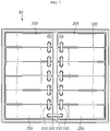
- FIG. 11 is a front view for illustrating the battery rack according to another embodiment of the present disclosure.
- the positive electrode terminal 255 and the negative electrode terminal 257 of the battery module 250 provided in each of the first battery module assembly 203 and the second battery module assembly 204 are arranged at different positions, compared with the battery rack 10 shown in FIG. 7 .
- the positive electrode terminal 255 and the negative electrode terminal 257 may be biased to the left based on the center of the module.
- the positive electrode terminal 255 and the negative electrode terminal 257 may be biased to the right based on the center of the module.
- the plurality of battery modules 250B provided to the second battery module assembly 204 may have the same configuration as the plurality of battery modules 250A provided to the first battery module assembly 203, except that the plurality of battery modules 250B are arranged to be inverted in the upper and lower direction.
- the components included the plurality of battery modules 250B provided to the second battery module assembly 204 and the components included the plurality of battery modules 250A provided to the first battery module assembly 203 are symmetrically arranged in the left and right direction based on the center between the first battery module assembly 203 and the second battery module assembly 204.
- the first battery module assembly 203 may include a plurality of first bus bar members 310 elongated in the upper and lower direction along the stacking direction of the plurality of battery modules 250A. That is, the first bus bar member 310 may be configured to connect the negative electrode terminal 257 of one battery module 250A to the positive electrode terminal 255 of another battery module 250A.
- the second battery module assembly 204 may include a plurality of second bus bar members 330 elongated in the upper and lower direction along the stacking direction of the plurality of battery modules 250B. That is, the second bus bar member 330 may be configured to connect the positive electrode terminal 255 of one battery module 250B to the negative electrode terminal 257 of another battery module 250B.
- the battery rack 10A may include a connection bus bar member 350 configured to connect the positive electrode terminal 255 of the battery module 250B of the second battery module assembly 204 and the negative electrode terminal 257 of the battery module 250A of the first battery module assembly 203.
- each of the plurality of battery modules 250 may include at least two cell assemblies (not shown), and a battery management system 260.
- the cell assembly may include a plurality of battery cells.
- the cell assembly is described above, and thus will not be described in detail again.
- the battery management system 260 may be configured to control charging and discharging of the plurality of battery cells.
- the battery management system 260 may include electronic components (not shown).
- the electronic components may be a relay, a current sensor, a temperature sensor, a fuse, and the like. These electronic components may be components for managing charging and discharging of battery cells and securing safety.
- the battery rack 10A may further include a central control unit 400.
- the central control unit 400 may be configured to receive state information of the battery module 250 from the battery management system 260 provided to each of the plurality of battery modules 250 and control charging and discharging of the plurality of battery modules 250.
- the central control unit 400 may include a communication part (not shown) for sending and receiving a communication signal, an analyzing part (not shown) for analyzing the communication signal, a supplying part 410 for supplying power to an external device or an internal part, and a memory part (not shown) for storing analysis contents of the communication signal.
- the battery rack 10A may further include a cooling fan 270 and a fan power cable 275.
- the cooling fan 270 may be provided to each of the battery modules 250A, 250B.
- the cooling fan 270 may be configured to put an external air into the battery module 250.
- the cooling fan 270 may be a known cooling fan 270 that is commonly applied to a battery module. That is, the cooling fan 270 may include an electric motor and a blowing fan.
- the fan power cable 275 may include a wire (where a metal wire is embedded) configured to supply power to operate the cooling fan 270, and an electrically insulating tube covering the wire.
- the fan power cable 275 may include a power source 276 and a connector unit 278.
- the power source 276 may be electrically connected to the supplying part 410 of the central control unit 400 to supply power to the cooling fan 270.
- the fan power cable 275 may have a power source 276 provided at a distal end thereof and electrically connected to the supplying part 410 of the central control unit 400.
- the connector unit 278 may be connected to an external power terminal of the cooling fan 270 provided to each of the first battery module assembly 203 and the second battery module assembly 204.
- the connector unit 278 may be configured to branch in left and right directions toward the plurality of battery modules 250 provided to each of the first battery module assembly 203 and the second battery module assembly 204.
- the connector unit 278 may be configured to extend in the upper and lower direction between the first battery module assembly 203 and the second battery module assembly 204.
- the connector unit 278 of the fan power cable 275 may include a first connector portion 278a and a second connector portion 278b.
- the first connector portion 278a may have a structure branching to each of the plurality of battery modules 250 of the first battery module assembly 203.
- the second connector portion 278b may have a structure spaced apart from the first connector portion 278a in the upper and lower direction and branching to each of the plurality of battery modules 250 of the second battery module assembly 204.
- the fan power cable 275 includes a power source 276 electrically connected to the central control unit 400 to supply power to the cooling fan 270 and a connector unit 278 branching in left and right directions toward the plurality of battery modules 250 provided to each of the first battery module assembly 203 and the second battery module assembly 204 and connected to the external power terminal of the cooling fan 270, the cooling fan 270 provided to each of the first battery module assembly 203 and the second battery module assembly 204 may be more easily connected to the central control unit 400 by means of the fan power cable 275 configured as above.
- the battery modules 250A of the first battery module assembly 203 and the battery modules 250B of the second battery module assembly 204 are arranged such that their configurations are disposed oppositely in the left and right directions, and thus the connection distance of the fan power cable 275 for electrically connecting the provided cooling fans 270 may be realized in the shortest distance.
- the present disclosure may eliminate the inevitable disadvantages of the prior art where two fan power cables are respectively used for battery module assemblies vertically stacked in two rows since the distance is too long to connect the fan power cables in parallel connection to supply power to the cooling fans of the battery module assemblies vertically stacked in two rows.
- the battery rack 10A may further include a communication cable 280.
- the communication cable 280 may be configured to transmit and receive a communication signal between the central control unit 400 and the battery management system 260 provided to each of the plurality of battery modules 250.
- the communication cable 280 may be configured to transmit information such as temperature, current and voltage of the battery module 250.
- the communication cable 280 may use a known communication cable commonly applied to a battery rack. Accordingly, the communication cable 280 will not be described in detail here.
- the communication cable 280 may include a connection portion 282 and an extension portion 284.
- connection portion 282 may extend along the plurality of stacked battery modules 250 of the first battery module assembly 203 or the second battery module assembly 204.
- the connection portion 282 may be connected to the battery management system 260 provided to each of the plurality of battery modules 250.
- the extension portion 284 may extend to connect the battery management systems 260 provided to the first battery module assembly 203 and the second battery module assembly 204 with each other.
- the extension portion 284 may have a structure extending from the battery module 250A at the bottom end of the first battery module assembly 203 to the battery module 250B at the bottom end of the second battery module assembly 204.
- the extension portion 284 of the communication cable 280 extends to be connected from the battery module 250A at the bottom end of the first battery module assembly 203 to the battery module 250B at the bottom end of the second battery module assembly 204, it is possible to more conveniently connect the central control unit 400 to the battery management system 260 provided to each of the first battery module assembly 203 and the second battery module assembly 204 through the communication cable 280 configured as above.
- the battery modules 250A of the first battery module assembly 203 and the battery modules 250B of the second battery module assembly 204 are arranged such that their configurations are disposed oppositely in the left and right directions, and thus the connection distance of the communication cable 280 for communication between the central control unit 400 and the battery management system 260 may be realized in the shortest distance.
- connection structure of the communication cable 280 it is possible to reduce the manufacturing cost and installation time of components. That is, in the prior art, in order to connect the communication cables of battery module assemblies vertically stacked in two rows, it is inevitable to connect the battery module at the bottom end of the battery module assembly disposed at the right to the battery module at the top of the battery module assembly disposed at the left. For this reason, the length of the communication cable increases greatly, which increases the material cost and causes inconvenience to the user after the battery rack is installed.
- the present disclosure effectively solves the problem of the prior art by minimizing the connection length of the communication cable 280.
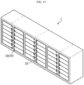
- FIG. 12 is a diagram for illustrating an energy storage system according to an embodiment of the present disclosure.
- an energy storage system 1 is an energy source and may be used for home or industrial use.
- the energy storage system 1 may include at least one battery rack 10, 20 of the former embodiment, or a plurality of battery racks 10, 20 in this embodiment, and a rack container 50 for accommodating the plurality of battery racks 10, 20.
- the energy storage system 1 includes the battery rack 10, 20 of the former embodiment, it is possible to provide an energy storage system 1 that includes all the advantages of the battery rack 10, 20 of the former embodiment.
- the battery rack 10, 20 of the former embodiment may also be provided to vehicles such as electric vehicles, or other facilities such as other devices or appliances having a secondary battery as an energy source, in addition to the energy storage system 1.
- a battery rack 10, 20 capable of efficiently connecting terminals of battery modules 250, 252, and an energy storage system 1 including the battery rack 10, 20.
- a battery rack 10, 20 capable of reducing manufacturing costs and improving assembly process efficiency, and an energy storage system 1 including the battery rack 10, 20.
- Reference Signs 1 energy storage system 10: battery rack 20: battery rack 50: rack container 100: rack case 200, 203, 207: first battery module assembly 204, 205, 208: second battery module assembly 250, 252: battery module 251: battery cell 253: module case 255: positive electrode terminal 257: negative electrode terminal 259: identifying member 300: bus bar unit 310: first bus bar member 330: second bus bar member 350: connection bus bar member 260: battery management system 400: central control unit 270: cooling fan 275: fan power cable 276, 278: power source, connector unit 280: communication cable 282, 284: connection portion, extension portion
- the present disclosure relates to a battery rack.
- the present disclosure may be used in industries related to a large-scale energy storage system including the battery rack.
Landscapes
- Chemical & Material Sciences (AREA)
- Chemical Kinetics & Catalysis (AREA)
- Electrochemistry (AREA)
- General Chemical & Material Sciences (AREA)
- Engineering & Computer Science (AREA)
- Manufacturing & Machinery (AREA)
- Microelectronics & Electronic Packaging (AREA)
- Battery Mounting, Suspending (AREA)
- Connection Of Batteries Or Terminals (AREA)
- Secondary Cells (AREA)
Abstract
Description
- The present disclosure relates to a battery rack and an energy storage system including the battery rack.
- The present application claims priority to
Korean Patent Application No. 10-2019-0111599 filed on September 9, 2019 - Secondary batteries which are highly applicable to various products and exhibit superior electrical properties such as high energy density, etc. are commonly used not only in portable devices but also in electric vehicles (EVs) or hybrid electric vehicles (HEVs) driven by electrical power sources. The secondary battery is drawing attentions as a new energy source for enhancing environment friendliness and energy efficiency in that the use of fossil fuels can be reduced greatly and no byproduct is generated during energy consumption.
- Secondary batteries widely used at present include lithium ion batteries, lithium polymer batteries, nickel cadmium batteries, nickel hydrogen batteries, nickel zinc batteries and the like. An operating voltage of the unit secondary battery cell, namely a unit battery cell, is about 2.5V to 4.5V. Therefore, if a higher output voltage is required, a plurality of battery cells may be connected in series to configure a battery pack. In addition, depending on the charge/discharge capacity required for the battery pack, a plurality of battery cells may be connected in parallel to configure a battery pack. Thus, the number of battery cells included in the battery pack may be variously set according to the required output voltage or the demanded charge/discharge capacity.
- Meanwhile, when a plurality of battery cells are connected in series or in parallel to configure a battery pack, it is common to configure a battery module including at least one battery cell first, and then configure a battery rack by using at least one battery module and adding other components. Here, according to various voltage and capacity requirements, an energy storage system may be configured to include at least one battery rack that includes at least one battery module.
- The conventional battery rack is configured to include a plurality of battery modules and a rack case for accommodating the plurality of battery modules. Here, the plurality of battery modules are generally arranged to be vertically stacked in a line inside the rack case along an upper and lower direction of the rack case, and are electrically connected to each other via a bus bar unit that connects terminals of the battery modules inside the rack case for electrical connection with each other.
- Meanwhile, recently, the capacity increase of the battery rack is accelerating according to the request of customers. Accordingly, when the plurality of battery modules are vertically stacked in the rack case, the need for a two-row vertical stacking structure is increasing instead of a one-row structure.
- However, in the case of the plurality of battery modules having a two-row vertical stacking structure, it is not easy to connect the terminals of the battery modules. Conventionally, in the two-row vertical stacking structure, for electrical connection between a terminal of one battery module and a terminal of another battery module, a bus bar unit having a very long length and bent multiple times or extended diagonally is needed. Accordingly, due to the bus bar unit, the overall electrical connection of the battery modules has a complicated shape, which is disadvantageous in terms of space utilization. In addition, the bus bar unit causes the increase of manufacturing costs and increases the overall assembly process time.
- Therefore, it is needed to find a way for providing a battery rack capable of efficiently connecting terminals of battery modules and reducing manufacturing cost, and an energy storage system including the battery rack.
- The present disclosure is directed to providing a battery rack capable of efficiently connecting terminals of battery modules, and an energy storage system including the battery rack.
- In addition, the present disclosure is also directed to providing a battery rack capable of reducing manufacturing costs and improving assembly process efficiency, and an energy storage system including the battery rack.
- In one aspect of the present disclosure, there is provided a battery rack, comprising:
- a rack case having a predetermined accommodation space;
- a first battery module assembly disposed inside the rack case and including a plurality of battery modules stacked along an upper and lower direction of the rack case; and
- a second battery module assembly disposed to be spaced apart from the first battery module assembly by a predetermined distance and including a plurality of battery modules stacked along the upper and lower direction of the rack case,
- wherein, inside the rack case, the plurality of battery modules of the second battery module assembly are arranged such that upper and lower portions thereof are inverted based on the arrangement of the plurality of battery modules of the first battery module assembly.
- The battery rack may further comprise a bus bar unit configured to electrically connect the plurality of battery modules of the first battery module assembly and the plurality of battery modules of the second battery module assembly.
- The bus bar unit may be provided to have a straight bar shape.
- The bus bar unit may include a plurality of first bus bar members configured to connect the plurality of battery modules of the first battery module assembly to each other; a plurality of second bus bar members configured to connect the plurality of battery modules of the second battery module assembly to each other; and a connection bus bar member configured to connect the first battery module assembly and the second battery module assembly to each other.
- The connection bus bar member may be configured to connect a battery module at a bottom end of the first battery module assembly and a battery module at a bottom end of the second battery module assembly to each other.
- The connection bus bar member may be provided to have a straight bar shape and configured to connect the battery module at the bottom end of the first battery module assembly and the battery module at the bottom end of the second battery module assembly to each other in a horizontal direction of the rack case.
- Each of the plurality of battery modules may include at least one battery cell; a module case configured to accommodate the at least one battery cell; and a positive electrode terminal and a negative electrode terminal provided at one side of the module case and electrically connected to the at least one battery cell.
- The positive electrode terminal and the negative electrode terminal may be arranged in an upper and lower direction at one end of the module case.
- Each of the plurality of battery modules may include an identifying member provided to the module case and configured to determine whether the battery modules are arranged in a forward direction or a rearward direction based on the upper and lower direction of the rack case.
- In addition, each of the plurality of battery modules may include at least two cell assemblies having a plurality of battery cells; and a battery management system configured to control charging and discharging of the plurality of battery cells.
- Further, the battery rack may include a central control unit configured to receive state information of the battery module from the battery management system provided to each of the plurality of battery modules and control charging and discharging of the plurality of battery modules.
- Also, the battery rack may include:
- a cooling fan provided to each of the plurality of battery modules and configured to put an external air into the battery module; and
- a fan power cable configured to supply power to operate the cooling fan.
- Moreover, the fan power cable may include:
- a power source electrically connected to the central control unit to supply power to the cooling fan; and
- a connector unit configured to branch in left and right directions toward the plurality of battery modules respectively provided to the first battery module assembly and the second battery module assembly and connected to an external power terminal of the cooling fan.
- In addition, the connector unit of the fan power cable may include:
- a first connector portion configured to branch to each of the plurality of battery modules of the first battery module assembly; and
- a second connector portion configured to branch to each of the plurality of battery modules of the second battery module assembly.
- Further, the battery rack may further comprise a communication cable configured to provide and receive a communication signal between the central control unit and the battery management system provided to each of the plurality of battery modules.
- Also, the communication cable may include:
- a connection portion configured to extend along the plurality of stacked battery modules of the first battery module assembly or the second battery module assembly and connected to the battery management system provided to each of the plurality of battery modules; and
- an extension portion configured to extend to connect the battery management systems respectively provided to the first battery module assembly and the second battery module assembly to each other,
- wherein the extension portion may be configured to extend from a battery module at a bottom end of the first battery module assembly to a battery module at a bottom end of the second battery module assembly.
- Moreover, the present disclosure also provides an energy storage system, comprising at least one battery rack according to the above embodiments.
- According to various embodiments as described above, it is possible to provide a battery rack capable of efficiently connecting terminals of battery modules, and an energy storage system including the battery rack.
- In addition, according to various embodiments as described above, it is possible to provide a battery rack capable of reducing manufacturing costs and improving assembly process efficiency, and an energy storage system including the battery rack.
- The accompanying drawings illustrate a preferred embodiment of the present disclosure and together with the foregoing disclosure, serve to provide further understanding of the technical features of the present disclosure, and thus, the present disclosure is not construed as being limited to the drawing.
-
FIG. 1 is a diagram for illustrating a battery rack according to an embodiment of the present disclosure. -
FIG. 2 is a diagram for illustrating a battery module of a first battery module assembly, provided to the battery rack ofFIG. 1 . -
FIG. 3 is a diagram for illustrating a battery module of a second battery module assembly, provided to the battery rack ofFIG. 1 . -
FIGS. 4 to 8 are diagrams for illustrating a process of assembling the battery rack ofFIG. 1 . -
FIGS. 9 and 10 are diagrams for illustrating a battery rack according to another embodiment of the present disclosure. -
FIG. 11 is a front view for illustrating the battery rack according to another embodiment of the present disclosure. -
FIG. 12 is a diagram for illustrating an energy storage system according to an embodiment of the present disclosure. - The present disclosure will become more apparent by describing in detail the embodiments of the present disclosure with reference to the accompanying drawings. It should be understood that the embodiments disclosed herein are illustrative only for better understanding of the present disclosure, and that the present disclosure may be modified in various ways. In addition, for ease understanding of the present disclosure, the accompanying drawings are not drawn to real scale, but the dimensions of some components may be exaggerated.
-
FIG. 1 is a diagram for illustrating a battery rack according to an embodiment of the present disclosure,FIG. 2 is a diagram for illustrating a battery module of a first battery module assembly, provided to the battery rack ofFIG. 1 , andFIG. 3 is a diagram for illustrating a battery module of a second battery module assembly, provided to the battery rack ofFIG. 1 . - Referring to
FIGS. 1 to 3 , abattery rack 10 may include arack case 100, a firstbattery module assembly 200, a secondbattery module assembly 205, and abus bar unit 300. - The
rack case 100 is configured to accommodate the firstbattery module assembly 200 and the secondbattery module assembly 205, explained later, and may have a predetermined accommodation space for this purpose. - The first
battery module assembly 200 is disposed inside therack case 100, and may include a plurality ofbattery modules 250. - The plurality of
battery modules 250 may be vertically stacked inside therack case 100 along an upper and lower direction of therack case 100. Each of thebattery modules 250 may include abattery cell 251, amodule case 253, apositive electrode terminal 255, and anegative electrode terminal 257. - The
battery cell 251 is a secondary battery and may be provided as a pouch-type secondary battery, a rectangular secondary battery, or a cylindrical secondary battery. Hereinafter, in this embodiment, it will be described that thebattery cell 251 is a pouch-type secondary battery. - At least one
battery cell 251 or a plurality ofbattery cells 251 may be provided. Hereinafter, in this embodiment, it will be described that thebattery cell 251 is provided in plural. - The
module case 253 may accommodate the at least onebattery cell 251 or the plurality ofbattery cells 251. To this end, the accommodation space for accommodating thebattery cell 251 may be provided in themodule case 253. - The
positive electrode terminal 255 is electrically connected to the at least onebattery cell 251 or the plurality ofbattery cells 251 and may be provided at one side of themodule case 253. Specifically, thepositive electrode terminal 255 may be disposed at the front of one end of themodule case 253. - The
negative electrode terminal 257 is electrically connected to the at least onebattery cell 251 or the plurality ofbattery cells 251 and may be provided at one side of themodule case 253. Specifically, thenegative electrode terminal 257 may be disposed at the front of one end of themodule case 253 and may be arranged in an upper and lower direction with respect to thepositive electrode terminal 255 at one end of themodule case 253. - In this embodiment, in each of the
battery modules 250 of the firstbattery module assembly 200, in the upper and lower direction of therack case 100, thepositive electrode terminal 255 may be disposed above thenegative electrode terminal 257. - The second
battery module assembly 205 may be disposed to be spaced apart from the firstbattery module assembly 200 by a predetermined distance in a horizontal direction. The secondbattery module assembly 205 may include a plurality ofbattery modules 250 vertically stacked along the upper and lower direction of therack case 100. - The second
battery module assembly 205 and the firstbattery module assembly 200 may form a two-row vertical stacking structure inside therack case 100. Accordingly, thebattery rack 10 according to this embodiment may implement a large-capacity battery rack 10 with a higher energy density. - The plurality of
battery modules 250 of the secondbattery module assembly 205 may also include abattery cell 251, amodule case 253, apositive electrode terminal 255, and anegative electrode terminal 257. - In the
rack case 100, the plurality ofbattery modules 250 of the secondbattery module assembly 205 are arranged such that upper and lower portions thereof are inverted based on the arrangement of the plurality ofbattery modules 250 of the firstbattery module assembly 200. - Accordingly, in the plurality of
battery modules 250 of the secondbattery module assembly 205, in the upper and lower direction of therack case 100, thepositive electrode terminal 255 may be disposed under thenegative electrode terminal 257. Conversely, in the plurality ofbattery modules 250 of the firstbattery module assembly 200, in the upper and lower direction of therack case 100, thepositive electrode terminal 255 may be disposed above thenegative electrode terminal 257. - That is, the plurality of
battery modules 250 of the firstbattery module assembly 200 may be arranged in a forward direction based on the upper and lower direction of therack case 100, and the plurality ofbattery modules 250 of the secondbattery module assembly 205 may be arranged in a rearward direction based on the upper and lower direction of therack case 100. Here, the forward direction may refer to a direction in which thepositive electrode terminal 255 is disposed above thenegative electrode terminal 257 based on the upper and lower direction of therack case 100, and the rearward direction may refer to a direction in which thepositive electrode terminal 255 is disposed below thenegative electrode terminal 257 based on the upper and lower direction of therack case 100. - According to this arrangement, the
positive electrode terminal 255 and thenegative electrode terminal 257 of the plurality ofbattery modules 250 of the secondbattery module assembly 205 disposed at the right of the firstbattery module assembly 200 may be disposed at the front of the left end of themodule case 253, and thepositive electrode terminal 255 and thenegative electrode terminal 257 of the plurality ofbattery modules 250 of the firstbattery module assembly 200 may be disposed at the front of the right end of themodule case 253, so that theirterminals - The
bus bar unit 300 may electrically connect the plurality ofbattery modules 250 of the firstbattery module assembly 200 and the plurality ofbattery modules 250 of the secondbattery module assembly 205. - The
bus bar unit 300 may include a firstbus bar member 310, a secondbus bar member 330, and a connectionbus bar member 350. - The first
bus bar member 310 is provided to have a straight bar shape elongated in one direction and may be provided in plural. The plurality of firstbus bar members 310 may connect the plurality ofbattery modules 250 of the firstbattery module assembly 200 to each other. - The second
bus bar member 330 is provided to have a straight bar shape elongated in one direction and may be provided in plural, like the firstbus bar member 310. The plurality of secondbus bar members 330 may connect the plurality ofbattery modules 250 of the secondbattery module assembly 205 to each other. - The connection
bus bar member 350 may be provided to have a straight bar shape elongated in one direction, like the firstbus bar member 310 and the secondbus bar member 330. That is, in this embodiment, all the firstbus bar member 310, the secondbus bar member 330 and the connectionbus bar member 350 may be provided in a straight bar shape. After all, in this embodiment, thebus bar units 300 may be provided to have the same straight bar shape. In other words, the bus bar units may have a simple shape, rather than a complicatedly bent shape. - The connection
bus bar member 350 may connect the firstbattery module assembly 200 and the secondbattery module assembly 205 to each other. Specifically, the connectionbus bar member 350 may connect abattery module 250 at a bottom end of the firstbattery module assembly 200 and abattery module 250 at a bottom end of the secondbattery module assembly 205 to each other. More specifically, the connectionbus bar member 350 may connect thenegative electrode terminal 257 of thebattery module 250 at the bottom end of the firstbattery module assembly 200 and thepositive electrode terminal 255 of thebattery module 250 at the bottom end of the secondbattery module assembly 205 to each other in a horizontal direction of therack case 100. - At this time, the
positive electrode terminal 255 and thenegative electrode terminal 257 are formed at the front of the right end of thebattery module 250 of the firstbattery module assembly 200, and thenegative electrode terminal 257 and thepositive electrode terminal 255 are formed at the front of the left end of thebattery module 250 of the secondbattery module assembly 205. Accordingly, thenegative electrode terminal 257 of thebattery module 250 of the firstbattery module assembly 200 may be located close to thepositive electrode terminal 255 of thebattery module 250 of the secondbattery module assembly 205. - Therefore, according to this configuration of the present disclosure, since the plurality of battery modules of the second battery module assembly are arranged inside the rack case such that their upper and lower portions are inverted based on the arrangement of the plurality of battery modules of the first battery module assembly, the length of the connection
bus bar member 350 for connecting the firstbattery module assembly 200 and the secondbattery module assembly 205 to each other may be minimized. - That is, in the prior art, if the first battery module assembly and the second battery module assembly arranged in the left and right direction inside the rack case are arranged in the same pattern, their electrode terminals are formed at one sides of the battery modules and thus far away from each other, so the conventional connection bus bar member needs to be formed as long as the left and right length of the battery module. Moreover, the connection bus bar member of the elongated structure not only increases material cost, but also blocks the front of the battery module after installation, which makes a worker using the battery module uncomfortable. Therefore, the battery rack of the present disclosure may greatly reduce the length of the connection bus bar member, thereby reducing the manufacturing cost of the battery rack and greatly increasing the convenience of use.
- Hereinafter, the assembly process of the
battery rack 10 according to this embodiment will be described in more detail. -
FIGS. 4 to 8 are diagrams for illustrating a process of assembling the battery rack ofFIG. 1 . - Referring to
FIG. 4 , in the assembly process of thebattery rack 10, a manufacturer or the like may vertically stack thebattery modules 250 of the firstbattery module assembly 200 in therack case 100. Here, thebattery modules 250 of the firstbattery module assembly 200 may be arranged in a forward direction based on the upper and lower direction of therack case 100. - Referring to
FIGS. 5 and6 , the manufacturer or the like may vertically stack thebattery modules 250 of the secondbattery module assembly 205 in therack case 100. Here, before stacking thebattery modules 250 of the secondbattery module assembly 205, the manufacturer or the like may invert thebattery modules 250 into a rearward direction first. That is, the manufacturer or the like may arrange thebattery modules 250 of the secondbattery module assembly 205 in the rearward direction and then vertically stack thebattery modules 250 inside therack case 100. - As the vertical stacking of the second
battery module assembly 205, the firstbattery module assembly 200 and the secondbattery module assembly 205 may be arranged in a two-row vertical stacking structure inside therack case 100. - Referring to
FIGS. 7 and8 , if the firstbattery module assembly 200 and the secondbattery module assembly 205 are completely stacked, the manufacturer or the like may electrically connect the firstbattery module assembly 200 and the secondbattery module assembly 205 by means of thebus bar unit 300. - Specifically, the vertically stacked
battery modules 250 of the firstbattery module assembly 200 may be electrically connected to each other through the plurality of firstbus bar members 310, and the vertically stackedbattery modules 250 of the secondbattery module assembly 205 may be electrically connected to each other through the plurality of secondbus bar members 330. - In addition, through the connection
bus bar member 350, the firstbattery module assembly 200 and the secondbattery module assembly 205 may be connected to each other. Specifically, the connectionbus bar member 350 may connect thenegative electrode terminal 257 of thebattery module 250 at the bottom end of the firstbattery module assembly 200 and thepositive electrode terminal 255 of thebattery module 250 at the bottom end of the secondbattery module assembly 205 to each other, in the horizontal direction of therack case 100. - In this embodiment, as the
battery modules 250 of the firstbattery module assembly 200 and thebattery modules 250 of the secondbattery module assembly 205 are arranged in opposite directions, thenegative electrode terminal 257 of thebattery module 250 at the bottom end of the firstbattery module assembly 200 and thepositive electrode terminal 255 of thebattery module 250 at the bottom end of the secondbattery module assembly 205 may be disposed to face each other with the shortest distance. - Accordingly, in this embodiment, the connection
bus bar member 350 may have a predetermined straight bar shape, like the firstbus bar member 310 and the secondbus bar member 330. Through the connectionbus bar member 350, the firstbattery module assembly 200 and the secondbattery module assembly 205 may be connected more conveniently. - That is, in this embodiment, when implementing the two-row vertical stacking structure of the first
battery module assembly 200 and the secondbattery module assembly 205, since thebattery modules 250 of the firstbattery module assembly 200 and thebattery modules 250 of the secondbattery module assembly 205 are arranged such that their upper and lower portions are inverted, the distance between theterminals bus bar unit 300 that connects the terminals. That is, the terminals may be conveniently connected through the connectionbus bar member 350 having a simple straight bar shape, without extending the connectionbus bar member 350 diagonally with a too long length or having a multi-stage bent structure as in the prior art. - Therefore, in this embodiment, when implementing the two-row vertical stacking structure of the first
battery module assembly 200 and the secondbattery module assembly 205, the terminal connection efficiency of thebattery modules 250, namely the wiring efficiency, may be remarkably increased. - Accordingly, in this embodiment, the overall electrical connection form of the
battery modules 250 may be remarkably simplified, and space utilization inside therack case 100 may be improved. - In addition, in this embodiment, the shape of the
bus bar unit 300 may also be simplified and unified uniformly, so it is possible to reduce the manufacturing cost of thebus bar unit 300 and significantly shorten the assembly process time for thebus bar unit 300. -
FIGS. 9 and 10 are diagrams for illustrating a battery rack according to another embodiment of the present disclosure. - Since a
battery rack 20 according to this embodiment is similar to thebattery rack 10 of the former embodiment, hereinafter, features substantially identical or similar to the former embodiment will not be described again, and features different from the former embodiment will be described in detail. - Referring to
FIGS. 9 and 10 , thebattery rack 20 may include arack case 100, a firstbattery module assembly 207, a secondbattery module assembly 208, and abus bar unit 300. - The
rack case 100 is substantially identical or similar to the former embodiment, and thus will not be described again. - Each of the first
battery module assembly 207 and the secondbattery module assembly 208 may include a plurality ofbattery modules 252. - Each of the plurality of
battery modules 252 may include abattery cell 251, amodule case 253, apositive electrode terminal 255, anegative electrode terminal 257, and an identifyingmember 259. - The
battery cell 251, themodule case 253, thepositive electrode terminal 255 and thenegative electrode terminal 257 are substantially identical or similar to the former embodiment, and thus will not be described again. - The identifying
member 259 is provided to themodule case 253 and allows to determine whether the arrangement state of thebattery module 252 is a forward direction or a rearward direction based on the upper and lower direction of therack case 100. - Specifically, the identifying
member 259 is provided at a front center of themodule case 253 and may be provided in an approximately triangular shape. The identifyingmember 259 may be arranged in an equilateral triangle shape in the forward direction and in an inverted triangle shape in the rearward direction. - Accordingly, the identifying
member 259 may be disposed in an equilateral triangle shape in the plurality ofbattery modules 252 of the firstbattery module assembly 207, and the identifyingmember 259 may be disposed in an inverted triangle shape in the plurality ofbattery modules 252 of the secondbattery module assembly 208. - Accordingly, the manufacturer or the like may more conveniently distinguish whether the arrangement state of the
battery modules 252 is the forward direction or the rearward direction by recognizing the identifyingmember 259, and thus it is possible to effectively prevent the risk of mis-assembly during electrical connection through thebus bar unit 300, explained later. - The
bus bar unit 300 may include a firstbus bar member 310, a secondbus bar member 330, and a connectionbus bar member 350. - The first
bus bar member 310, the secondbus bar member 330 and the connectionbus bar member 350 are substantially identical or similar to the former embodiment, and thus will not be described again. - As described above, in the
battery rack 20 according to this embodiment, the risk of assembly failure caused by incorrect assembly may be significantly reduced by means of the identifyingmember 259 during the assembly process for thebattery rack 10. -
FIG. 11 is a front view for illustrating the battery rack according to another embodiment of the present disclosure. - Referring to
FIG. 11 , in abattery rack 10A according to another embodiment, thepositive electrode terminal 255 and thenegative electrode terminal 257 of thebattery module 250 provided in each of the firstbattery module assembly 203 and the secondbattery module assembly 204 are arranged at different positions, compared with thebattery rack 10 shown inFIG. 7 . - Specifically, in a plurality of
battery modules 250A provided to the firstbattery module assembly 203, thepositive electrode terminal 255 and thenegative electrode terminal 257 may be biased to the left based on the center of the module. In addition, in a plurality ofbattery modules 250B provided to the secondbattery module assembly 204, thepositive electrode terminal 255 and thenegative electrode terminal 257 may be biased to the right based on the center of the module. - In addition, the plurality of
battery modules 250B provided to the secondbattery module assembly 204 may have the same configuration as the plurality ofbattery modules 250A provided to the firstbattery module assembly 203, except that the plurality ofbattery modules 250B are arranged to be inverted in the upper and lower direction. In other words, the components included the plurality ofbattery modules 250B provided to the secondbattery module assembly 204 and the components included the plurality ofbattery modules 250A provided to the firstbattery module assembly 203 are symmetrically arranged in the left and right direction based on the center between the firstbattery module assembly 203 and the secondbattery module assembly 204. - Further, the first
battery module assembly 203 may include a plurality of firstbus bar members 310 elongated in the upper and lower direction along the stacking direction of the plurality ofbattery modules 250A. That is, the firstbus bar member 310 may be configured to connect thenegative electrode terminal 257 of onebattery module 250A to thepositive electrode terminal 255 of anotherbattery module 250A. - The second
battery module assembly 204 may include a plurality of secondbus bar members 330 elongated in the upper and lower direction along the stacking direction of the plurality ofbattery modules 250B. That is, the secondbus bar member 330 may be configured to connect thepositive electrode terminal 255 of onebattery module 250B to thenegative electrode terminal 257 of anotherbattery module 250B. - The
battery rack 10A may include a connectionbus bar member 350 configured to connect thepositive electrode terminal 255 of thebattery module 250B of the secondbattery module assembly 204 and thenegative electrode terminal 257 of thebattery module 250A of the firstbattery module assembly 203. - Meanwhile, referring to
FIG. 11 again, each of the plurality ofbattery modules 250 may include at least two cell assemblies (not shown), and abattery management system 260. - The cell assembly may include a plurality of battery cells. Here, the cell assembly is described above, and thus will not be described in detail again.
- The
battery management system 260 may be configured to control charging and discharging of the plurality of battery cells. Thebattery management system 260 may include electronic components (not shown). For example, the electronic components may be a relay, a current sensor, a temperature sensor, a fuse, and the like. These electronic components may be components for managing charging and discharging of battery cells and securing safety. - In addition, the
battery rack 10A may further include acentral control unit 400. Specifically, thecentral control unit 400 may be configured to receive state information of thebattery module 250 from thebattery management system 260 provided to each of the plurality ofbattery modules 250 and control charging and discharging of the plurality ofbattery modules 250. For example, thecentral control unit 400 may include a communication part (not shown) for sending and receiving a communication signal, an analyzing part (not shown) for analyzing the communication signal, a supplyingpart 410 for supplying power to an external device or an internal part, and a memory part (not shown) for storing analysis contents of the communication signal. - Moreover, the
battery rack 10A may further include a coolingfan 270 and afan power cable 275. - The cooling
fan 270 may be provided to each of thebattery modules fan 270 may be configured to put an external air into thebattery module 250. Here, the coolingfan 270 may be a known coolingfan 270 that is commonly applied to a battery module. That is, the coolingfan 270 may include an electric motor and a blowing fan. - In addition, the
fan power cable 275 may include a wire (where a metal wire is embedded) configured to supply power to operate the coolingfan 270, and an electrically insulating tube covering the wire. - Further, the
fan power cable 275 may include apower source 276 and aconnector unit 278. - Specifically, the
power source 276 may be electrically connected to the supplyingpart 410 of thecentral control unit 400 to supply power to the coolingfan 270. For example, as shown inFIG. 11 , thefan power cable 275 may have apower source 276 provided at a distal end thereof and electrically connected to the supplyingpart 410 of thecentral control unit 400. - The
connector unit 278 may be connected to an external power terminal of the coolingfan 270 provided to each of the firstbattery module assembly 203 and the secondbattery module assembly 204. For example, theconnector unit 278 may be configured to branch in left and right directions toward the plurality ofbattery modules 250 provided to each of the firstbattery module assembly 203 and the secondbattery module assembly 204. In addition, theconnector unit 278 may be configured to extend in the upper and lower direction between the firstbattery module assembly 203 and the secondbattery module assembly 204. - In addition, the
connector unit 278 of thefan power cable 275 may include afirst connector portion 278a and asecond connector portion 278b. - The
first connector portion 278a may have a structure branching to each of the plurality ofbattery modules 250 of the firstbattery module assembly 203. - The
second connector portion 278b may have a structure spaced apart from thefirst connector portion 278a in the upper and lower direction and branching to each of the plurality ofbattery modules 250 of the secondbattery module assembly 204. - Therefore, according to this configuration of the present disclosure, since the
fan power cable 275 includes apower source 276 electrically connected to thecentral control unit 400 to supply power to the coolingfan 270 and aconnector unit 278 branching in left and right directions toward the plurality ofbattery modules 250 provided to each of the firstbattery module assembly 203 and the secondbattery module assembly 204 and connected to the external power terminal of the coolingfan 270, the coolingfan 270 provided to each of the firstbattery module assembly 203 and the secondbattery module assembly 204 may be more easily connected to thecentral control unit 400 by means of thefan power cable 275 configured as above. - That is, in this embodiment, when implementing the two-row vertical stacking structure of the first
battery module assembly 203 and the secondbattery module assembly 204, thebattery modules 250A of the firstbattery module assembly 203 and thebattery modules 250B of the secondbattery module assembly 204 are arranged such that their configurations are disposed oppositely in the left and right directions, and thus the connection distance of thefan power cable 275 for electrically connecting the provided coolingfans 270 may be realized in the shortest distance. - Accordingly, by simplifying the connection structure of the
fan power cable 275, it is possible to reduce the manufacturing cost and installation time of components. In other words, the present disclosure may eliminate the inevitable disadvantages of the prior art where two fan power cables are respectively used for battery module assemblies vertically stacked in two rows since the distance is too long to connect the fan power cables in parallel connection to supply power to the cooling fans of the battery module assemblies vertically stacked in two rows. - Meanwhile, referring to
FIG. 11 again, thebattery rack 10A may further include acommunication cable 280. Thecommunication cable 280 may be configured to transmit and receive a communication signal between thecentral control unit 400 and thebattery management system 260 provided to each of the plurality ofbattery modules 250. For example, thecommunication cable 280 may be configured to transmit information such as temperature, current and voltage of thebattery module 250. - The
communication cable 280 may use a known communication cable commonly applied to a battery rack. Accordingly, thecommunication cable 280 will not be described in detail here. - The
communication cable 280 may include aconnection portion 282 and anextension portion 284. - The
connection portion 282 may extend along the plurality of stackedbattery modules 250 of the firstbattery module assembly 203 or the secondbattery module assembly 204. Theconnection portion 282 may be connected to thebattery management system 260 provided to each of the plurality ofbattery modules 250. - The
extension portion 284 may extend to connect thebattery management systems 260 provided to the firstbattery module assembly 203 and the secondbattery module assembly 204 with each other. - For example, the
extension portion 284 may have a structure extending from thebattery module 250A at the bottom end of the firstbattery module assembly 203 to thebattery module 250B at the bottom end of the secondbattery module assembly 204. - Therefore, according to this configuration of the present disclosure, since the
extension portion 284 of thecommunication cable 280 extends to be connected from thebattery module 250A at the bottom end of the firstbattery module assembly 203 to thebattery module 250B at the bottom end of the secondbattery module assembly 204, it is possible to more conveniently connect thecentral control unit 400 to thebattery management system 260 provided to each of the firstbattery module assembly 203 and the secondbattery module assembly 204 through thecommunication cable 280 configured as above. - That is, in this embodiment, when implementing the two-row vertical stacking structure of the first
battery module assembly 203 and the secondbattery module assembly 204, thebattery modules 250A of the firstbattery module assembly 203 and thebattery modules 250B of the secondbattery module assembly 204 are arranged such that their configurations are disposed oppositely in the left and right directions, and thus the connection distance of thecommunication cable 280 for communication between thecentral control unit 400 and thebattery management system 260 may be realized in the shortest distance. - Accordingly, by simplifying the connection structure of the
communication cable 280, it is possible to reduce the manufacturing cost and installation time of components. That is, in the prior art, in order to connect the communication cables of battery module assemblies vertically stacked in two rows, it is inevitable to connect the battery module at the bottom end of the battery module assembly disposed at the right to the battery module at the top of the battery module assembly disposed at the left. For this reason, the length of the communication cable increases greatly, which increases the material cost and causes inconvenience to the user after the battery rack is installed. - Therefore, the present disclosure effectively solves the problem of the prior art by minimizing the connection length of the
communication cable 280. -
FIG. 12 is a diagram for illustrating an energy storage system according to an embodiment of the present disclosure. - Referring to
FIG. 12 , anenergy storage system 1 is an energy source and may be used for home or industrial use. Theenergy storage system 1 may include at least onebattery rack battery racks rack container 50 for accommodating the plurality ofbattery racks - Since the
energy storage system 1 according to this embodiment includes thebattery rack energy storage system 1 that includes all the advantages of thebattery rack - Moreover, the
battery rack energy storage system 1. - According to various embodiments as described above, it is possible to provide a
battery rack battery modules energy storage system 1 including thebattery rack - In addition, according to various embodiments as described above, it is possible to provide a
battery rack energy storage system 1 including thebattery rack - Meanwhile, even though the terms indicating directions such as upper, lower, left, right, front and rear directions are used in the specification, it is obvious to those skilled in the art that these merely represent relative locations for convenience in explanation and may vary based on a location of an observer or an object.
- The present disclosure has been described in detail. However, it should be understood that the detailed description and specific examples, while indicating preferred embodiments of the disclosure, are given by way of illustration only, since various changes and modifications within the scope of the disclosure will become apparent to those skilled in the art from this detailed description.
Reference Signs 1: energy storage system 10: battery rack 20: battery rack 50: rack container 100: rack case 200, 203, 207: first battery module assembly 204, 205, 208: second battery module assembly 250, 252: battery module 251: battery cell 253: module case 255: positive electrode terminal 257: negative electrode terminal 259: identifying member 300: bus bar unit 310: first bus bar member 330: second bus bar member 350: connection bus bar member 260: battery management system 400: central control unit 270: cooling fan 275: fan power cable 276, 278: power source, connector unit 280: communication cable 282, 284: connection portion, extension portion - The present disclosure relates to a battery rack. In addition, the present disclosure may be used in industries related to a large-scale energy storage system including the battery rack.
Claims (15)
- A battery rack, comprising:a rack case having a predetermined accommodation space;a first battery module assembly disposed inside the rack case and including a plurality of battery modules stacked along an upper and lower direction of the rack case; anda second battery module assembly disposed to be spaced apart from the first battery module assembly by a predetermined distance and including a plurality of battery modules stacked along the upper and lower direction of the rack case,wherein, inside the rack case, the plurality of battery modules of the second battery module assembly are arranged such that upper and lower portions thereof are inverted based on the arrangement of the plurality of battery modules of the first battery module assembly.
- The battery rack according to claim 1, further comprising:
a bus bar unit configured to electrically connect the plurality of battery modules of the first battery module assembly and the plurality of battery modules of the second battery module assembly. - The battery rack according to claim 2,
wherein the bus bar unit is provided to have a straight bar shape. - The battery rack according to claim 2,
wherein the bus bar unit includes:a plurality of first bus bar members configured to connect the plurality of battery modules of the first battery module assembly to each other;a plurality of second bus bar members configured to connect the plurality of battery modules of the second battery module assembly to each other; anda connection bus bar member configured to connect the first battery module assembly and the second battery module assembly to each other. - The battery rack according to claim 4,
wherein the connection bus bar member is configured to connect a battery module at a bottom end of the first battery module assembly and a battery module at a bottom end of the second battery module assembly to each other. - The battery rack according to claim 5,
wherein the connection bus bar member is provided to have a straight bar shape and configured to connect the battery module at the bottom end of the first battery module assembly and the battery module at the bottom end of the second battery module assembly to each other in a horizontal direction of the rack case. - The battery rack according to claim 2,
wherein each of the plurality of battery modules includes:at least one battery cell;a module case configured to accommodate the at least one battery cell; anda positive electrode terminal and a negative electrode terminal provided at one side of the module case and electrically connected to the at least one battery cell. - The battery rack according to claim 7,
wherein the positive electrode terminal and the negative electrode terminal are arranged in an upper and lower direction at one end of the module case. - The battery rack according to claim 7,
wherein each of the plurality of battery modules includes an identifying member provided to the module case and configured to determine whether the battery modules are arranged in a forward direction or a rearward direction based on the upper and lower direction of the rack case. - The battery rack according to claim 7,wherein each of the plurality of battery modules includes at least two cell assemblies having a plurality of battery cells; and a battery management system configured to control charging and discharging of the plurality of battery cells, andthe battery rack includes a central control unit configured to receive state information of the battery module from the battery management system provided to each of the plurality of battery modules and control charging and discharging of the plurality of battery modules.
- The battery rack according to claim 10,
wherein the battery rack includes:a cooling fan provided to each of the plurality of battery modules and configured to put an external air into the battery module; anda fan power cable configured to supply power to operate the cooling fan. - The battery rack according to claim 11,
wherein the fan power cable includes:a power source electrically connected to the central control unit to supply power to the cooling fan; anda connector unit configured to branch in left and right directions toward the plurality of battery modules respectively provided to the first battery module assembly and the second battery module assembly and connected to an external power terminal of the cooling fan. - The battery rack according to claim 12,
wherein the connector unit of the fan power cable includes:a first connector portion configured to branch to each of the plurality of battery modules of the first battery module assembly; anda second connector portion configured to branch to each of the plurality of battery modules of the second battery module assembly. - The battery rack according to claim 10, further comprising:a communication cable configured to provide and receive a communication signal between the central control unit and the battery management system provided to each of the plurality of battery modules,wherein the communication cable includes:a connection portion configured to extend along the plurality of stacked battery modules of the first battery module assembly or the second battery module assembly and connected to the battery management system provided to each of the plurality of battery modules; andan extension portion configured to extend to connect the battery management systems respectively provided to the first battery module assembly and the second battery module assembly to each other,wherein the extension portion is configured to extend from a battery module at a bottom end of the first battery module assembly to a battery module at a bottom end of the second battery module assembly.
- An energy storage system, comprising at least one battery rack according to claim 1.
Applications Claiming Priority (2)
| Application Number | Priority Date | Filing Date | Title |
|---|---|---|---|
| KR1020190111599A KR20210030090A (en) | 2019-09-09 | 2019-09-09 | Battery rack and energy storage system comprising the battery rack |
| PCT/KR2020/011889 WO2021049820A1 (en) | 2019-09-09 | 2020-09-03 | Battery rack and power storage device comprising same |
Publications (2)
| Publication Number | Publication Date |
|---|---|
| EP3926731A1 true EP3926731A1 (en) | 2021-12-22 |
| EP3926731A4 EP3926731A4 (en) | 2022-06-01 |
Family
ID=74867267
Family Applications (1)
| Application Number | Title | Priority Date | Filing Date |
|---|---|---|---|
| EP20863209.1A Pending EP3926731A4 (en) | 2019-09-09 | 2020-09-03 | BATTERY FRAME AND ENERGY STORAGE DEVICE COMPRISING THE SAME |
Country Status (7)
| Country | Link |
|---|---|
| US (1) | US12394858B2 (en) |
| EP (1) | EP3926731A4 (en) |
| JP (2) | JP2022517341A (en) |
| KR (1) | KR20210030090A (en) |
| CN (2) | CN113812033A (en) |
| AU (1) | AU2020347016B2 (en) |
| WO (1) | WO2021049820A1 (en) |
Families Citing this family (7)
| Publication number | Priority date | Publication date | Assignee | Title |
|---|---|---|---|---|
| JP7396321B2 (en) * | 2021-03-31 | 2023-12-12 | トヨタ自動車株式会社 | Energy storage units and vehicles |
| CN215644823U (en) * | 2021-07-28 | 2022-01-25 | 天合光能股份有限公司 | Energy storage unit and energy storage battery using the same |
| KR102851447B1 (en) * | 2022-11-16 | 2025-08-26 | 주식회사 엘지에너지솔루션 | Battery module and battery pack including the same |
| WO2025026239A1 (en) * | 2023-07-31 | 2025-02-06 | 比亚迪股份有限公司 | Energy storage device and energy storage system |
| CN118231901A (en) * | 2023-07-31 | 2024-06-21 | 比亚迪股份有限公司 | Energy storage device and energy storage system |
| KR20250086935A (en) * | 2023-12-07 | 2025-06-16 | 주식회사 엘지에너지솔루션 | Battery pack |
| US20250322996A1 (en) * | 2024-04-11 | 2025-10-16 | Systematic Power Manufacturing, Llc | Energy Storage Assembly Having Energy Storage Modules |
Family Cites Families (29)
| Publication number | Priority date | Publication date | Assignee | Title |
|---|---|---|---|---|
| US5140744A (en) * | 1990-06-06 | 1992-08-25 | Miller Robert D | Modular multicell battery and rack |
| WO2000030190A1 (en) | 1998-11-17 | 2000-05-25 | C & D Technologies, Inc. | Selectable capacity fixed footprint lead-acid battery racking system with horizontal plates |
| JP4778753B2 (en) | 2005-09-05 | 2011-09-21 | パナソニック株式会社 | Battery module |
| KR101147202B1 (en) | 2010-10-13 | 2012-05-25 | 삼성에스디아이 주식회사 | Power storage apparatus |
| DE102011106116A1 (en) * | 2011-05-30 | 2012-12-06 | Ads-Tec Gmbh | Battery block made of prismatic cells |
| WO2012165856A2 (en) | 2011-05-31 | 2012-12-06 | 주식회사 엘지화학 | Unit rack for power storage, and power storage device comprising same |
| JP5461686B2 (en) * | 2011-07-27 | 2014-04-02 | 株式会社日立製作所 | Battery system |
| JP2014232566A (en) | 2011-09-27 | 2014-12-11 | 三洋電機株式会社 | Battery system, electric vehicle, mobile, power unit, battery unit and housing body |
| JP6058260B2 (en) | 2011-10-28 | 2017-01-11 | 株式会社東芝 | Storage battery unit |
| US20140134460A1 (en) | 2012-11-13 | 2014-05-15 | Samsung Sdi Co., Ltd. | Energy storage system |
| US20150382496A1 (en) * | 2013-04-19 | 2015-12-31 | Richard Burant, Jr. | Electronic device and battery enclosure |
| CN103605389B (en) | 2013-11-29 | 2016-01-20 | 深圳先进储能材料国家工程研究中心有限公司 | A kind of panorama type micro-grid battery energy storage system method for managing temperature and system |
| JP2015115150A (en) | 2013-12-11 | 2015-06-22 | 新神戸電機株式会社 | Power storage device |
| KR101782984B1 (en) | 2014-03-19 | 2017-09-28 | 주식회사 엘지화학 | Battery Module Comprising Battery Cells or Unit Modules Having Multi- Directional Connection Structure |
| KR102284484B1 (en) | 2014-08-25 | 2021-08-02 | 삼성에스디아이 주식회사 | Rack housing assembly and energy stroge apparatus having the same |
| JP6686340B2 (en) | 2015-09-15 | 2020-04-22 | 株式会社Gsユアサ | Power storage device |
| KR102501081B1 (en) * | 2016-01-26 | 2023-02-17 | 삼성에스디아이 주식회사 | Battery assembly |
| CN109478699B (en) * | 2016-04-20 | 2022-05-17 | 康福斯能源公司 | Backplane assembly with power substructure and cooling substructure |
| KR102104383B1 (en) * | 2016-04-25 | 2020-04-24 | 주식회사 엘지화학 | Energy storage apparatus and method for cooling the energy storage apparatus |
| JP6686785B2 (en) | 2016-08-10 | 2020-04-22 | 株式会社村田製作所 | Power supply |
| US10062977B2 (en) * | 2016-10-14 | 2018-08-28 | Inevit Llc | Module-to-module power connector between battery modules of an energy storage system and arrangement thereof |
| KR20180048030A (en) | 2016-11-02 | 2018-05-10 | 삼성에스디아이 주식회사 | Rechargeable battery and module thereof |
| CN110088935B (en) * | 2016-12-26 | 2022-04-08 | 松下知识产权经营株式会社 | Rack-type power supply device |
| KR20250041618A (en) * | 2017-07-13 | 2025-03-25 | 에티움, 엘엘씨 | Modular lithium-ion battery system for fork lifts |
| JP6973180B2 (en) | 2018-02-28 | 2021-11-24 | トヨタ自動車株式会社 | Battery pack |
| KR102160784B1 (en) | 2018-03-23 | 2020-09-29 | 주식회사 세기종합환경 | Water solar generating facility using unit structure |
| US11038232B2 (en) * | 2018-05-08 | 2021-06-15 | Toshiba International Corporation | All front access battery rack system with insulated bus bar connection |
| US10797279B2 (en) * | 2018-06-28 | 2020-10-06 | Caterpillar Inc. | Battery housing systems |
| US20220052411A1 (en) * | 2018-11-28 | 2022-02-17 | Cadenza Innovation, Inc. | Modular Battery System |
-
2019
- 2019-09-09 KR KR1020190111599A patent/KR20210030090A/en active Pending
-
2020
- 2020-09-03 AU AU2020347016A patent/AU2020347016B2/en active Active
- 2020-09-03 US US17/424,404 patent/US12394858B2/en active Active
- 2020-09-03 EP EP20863209.1A patent/EP3926731A4/en active Pending
- 2020-09-03 WO PCT/KR2020/011889 patent/WO2021049820A1/en not_active Ceased
- 2020-09-03 CN CN202080033279.7A patent/CN113812033A/en active Pending
- 2020-09-03 JP JP2021540011A patent/JP2022517341A/en active Pending
- 2020-09-03 CN CN202410334329.5A patent/CN118198612A/en active Pending
-
2023
- 2023-12-28 JP JP2023222915A patent/JP7730884B2/en active Active
Also Published As
| Publication number | Publication date |
|---|---|
| CN118198612A (en) | 2024-06-14 |
| WO2021049820A1 (en) | 2021-03-18 |
| US20220094011A1 (en) | 2022-03-24 |
| AU2020347016B2 (en) | 2026-01-08 |
| EP3926731A4 (en) | 2022-06-01 |
| JP2022517341A (en) | 2022-03-08 |
| JP7730884B2 (en) | 2025-08-28 |
| CN113812033A (en) | 2021-12-17 |
| US12394858B2 (en) | 2025-08-19 |
| AU2020347016A1 (en) | 2021-10-14 |
| KR20210030090A (en) | 2021-03-17 |
| JP2024028359A (en) | 2024-03-04 |
Similar Documents
| Publication | Publication Date | Title |
|---|---|---|
| US12394858B2 (en) | Battery rack and energy storage system including the same | |
| US12261326B2 (en) | Battery module, battery pack including same battery module, and automobile including same battery pack | |
| US8912758B2 (en) | Power storage apparatus, power storage system having the same and method of assembling power storage system by using the same | |
| CN102804447B (en) | Battery module including novel structural sensing member | |
| EP3336928B1 (en) | Battery module, battery pack comprising battery module, and vehicle comprising battery pack | |
| US11018391B2 (en) | Battery cell, battery module, and battery pack and vehicle including the same | |
| EP3958375A1 (en) | Battery rack and power storage device comprising same | |
| US20220393320A1 (en) | Battery pack and vehicle comprising battery pack | |
| AU2025271176A1 (en) | Battery pack and power storage device comprising same | |
| AU2020311777A1 (en) | Battery module, battery rack comprising such battery module, and power storage device | |
| EP4027449A1 (en) | Battery module, and battery pack and vehicle including battery module | |
| EP4050722A1 (en) | Battery pack having connection plates, electronic device, and vehicle | |
| EP4027448A1 (en) | Battery module, battery pack comprising battery module, and vehicle | |
| EP4336623A1 (en) | Battery pack and energy storage device comprising same | |
| KR102714029B1 (en) | Battery module and battery pack including the same and vehicle including the same | |
| US20250233278A1 (en) | Conductive module | |
| KR102107220B1 (en) | Battery pack and vehicle comprising the battery pack | |
| KR20230057270A (en) | Battery system comprising cylindrical battery cells and a temperature sensor and method of installing the same | |
| KR20220091290A (en) | Battery pack |
Legal Events
| Date | Code | Title | Description |
|---|---|---|---|
| STAA | Information on the status of an ep patent application or granted ep patent |
Free format text: STATUS: THE INTERNATIONAL PUBLICATION HAS BEEN MADE |
|
| PUAI | Public reference made under article 153(3) epc to a published international application that has entered the european phase |
Free format text: ORIGINAL CODE: 0009012 |
|
| STAA | Information on the status of an ep patent application or granted ep patent |
Free format text: STATUS: REQUEST FOR EXAMINATION WAS MADE |
|
| 17P | Request for examination filed |
Effective date: 20210917 |
|
| AK | Designated contracting states |
Kind code of ref document: A1 Designated state(s): AL AT BE BG CH CY CZ DE DK EE ES FI FR GB GR HR HU IE IS IT LI LT LU LV MC MK MT NL NO PL PT RO RS SE SI SK SM TR |
|
| RAP3 | Party data changed (applicant data changed or rights of an application transferred) |
Owner name: LG ENERGY SOLUTION, LTD. |
|
| A4 | Supplementary search report drawn up and despatched |
Effective date: 20220502 |
|
| RIC1 | Information provided on ipc code assigned before grant |
Ipc: H01M 50/51 20210101ALI20220425BHEP Ipc: H01M 50/296 20210101ALI20220425BHEP Ipc: H01M 50/209 20210101ALI20220425BHEP Ipc: H01M 50/103 20210101ALI20220425BHEP Ipc: H01M 10/613 20140101ALI20220425BHEP Ipc: H01M 10/42 20060101ALI20220425BHEP Ipc: H01M 10/627 20140101ALI20220425BHEP Ipc: H01M 10/6563 20140101ALI20220425BHEP Ipc: H01M 10/48 20060101AFI20220425BHEP |
|
| DAV | Request for validation of the european patent (deleted) | ||
| DAX | Request for extension of the european patent (deleted) |