EP3926478B1 - Operating method of memory controller, operating method of host and storage device - Google Patents
Operating method of memory controller, operating method of host and storage device Download PDFInfo
- Publication number
- EP3926478B1 EP3926478B1 EP21159564.0A EP21159564A EP3926478B1 EP 3926478 B1 EP3926478 B1 EP 3926478B1 EP 21159564 A EP21159564 A EP 21159564A EP 3926478 B1 EP3926478 B1 EP 3926478B1
- Authority
- EP
- European Patent Office
- Prior art keywords
- memory
- lifespan
- host
- analysis result
- garbage collection
- Prior art date
- Legal status (The legal status is an assumption and is not a legal conclusion. Google has not performed a legal analysis and makes no representation as to the accuracy of the status listed.)
- Active
Links
Images






Classifications
-
- G—PHYSICS
- G06—COMPUTING OR CALCULATING; COUNTING
- G06F—ELECTRIC DIGITAL DATA PROCESSING
- G06F3/00—Input arrangements for transferring data to be processed into a form capable of being handled by the computer; Output arrangements for transferring data from processing unit to output unit, e.g. interface arrangements
- G06F3/06—Digital input from, or digital output to, record carriers, e.g. RAID, emulated record carriers or networked record carriers
- G06F3/0601—Interfaces specially adapted for storage systems
- G06F3/0628—Interfaces specially adapted for storage systems making use of a particular technique
- G06F3/0655—Vertical data movement, i.e. input-output transfer; data movement between one or more hosts and one or more storage devices
-
- G—PHYSICS
- G06—COMPUTING OR CALCULATING; COUNTING
- G06F—ELECTRIC DIGITAL DATA PROCESSING
- G06F12/00—Accessing, addressing or allocating within memory systems or architectures
- G06F12/02—Addressing or allocation; Relocation
- G06F12/0223—User address space allocation, e.g. contiguous or non contiguous base addressing
- G06F12/023—Free address space management
- G06F12/0238—Memory management in non-volatile memory, e.g. resistive RAM or ferroelectric memory
- G06F12/0246—Memory management in non-volatile memory, e.g. resistive RAM or ferroelectric memory in block erasable memory, e.g. flash memory
-
- G—PHYSICS
- G06—COMPUTING OR CALCULATING; COUNTING
- G06F—ELECTRIC DIGITAL DATA PROCESSING
- G06F12/00—Accessing, addressing or allocating within memory systems or architectures
- G06F12/02—Addressing or allocation; Relocation
- G06F12/0223—User address space allocation, e.g. contiguous or non contiguous base addressing
- G06F12/023—Free address space management
- G06F12/0253—Garbage collection, i.e. reclamation of unreferenced memory
-
- G—PHYSICS
- G06—COMPUTING OR CALCULATING; COUNTING
- G06F—ELECTRIC DIGITAL DATA PROCESSING
- G06F3/00—Input arrangements for transferring data to be processed into a form capable of being handled by the computer; Output arrangements for transferring data from processing unit to output unit, e.g. interface arrangements
- G06F3/06—Digital input from, or digital output to, record carriers, e.g. RAID, emulated record carriers or networked record carriers
- G06F3/0601—Interfaces specially adapted for storage systems
- G06F3/0602—Interfaces specially adapted for storage systems specifically adapted to achieve a particular effect
- G06F3/0604—Improving or facilitating administration, e.g. storage management
-
- G—PHYSICS
- G06—COMPUTING OR CALCULATING; COUNTING
- G06F—ELECTRIC DIGITAL DATA PROCESSING
- G06F3/00—Input arrangements for transferring data to be processed into a form capable of being handled by the computer; Output arrangements for transferring data from processing unit to output unit, e.g. interface arrangements
- G06F3/06—Digital input from, or digital output to, record carriers, e.g. RAID, emulated record carriers or networked record carriers
- G06F3/0601—Interfaces specially adapted for storage systems
- G06F3/0602—Interfaces specially adapted for storage systems specifically adapted to achieve a particular effect
- G06F3/0614—Improving the reliability of storage systems
- G06F3/0616—Improving the reliability of storage systems in relation to life time, e.g. increasing Mean Time Between Failures [MTBF]
-
- G—PHYSICS
- G06—COMPUTING OR CALCULATING; COUNTING
- G06F—ELECTRIC DIGITAL DATA PROCESSING
- G06F3/00—Input arrangements for transferring data to be processed into a form capable of being handled by the computer; Output arrangements for transferring data from processing unit to output unit, e.g. interface arrangements
- G06F3/06—Digital input from, or digital output to, record carriers, e.g. RAID, emulated record carriers or networked record carriers
- G06F3/0601—Interfaces specially adapted for storage systems
- G06F3/0628—Interfaces specially adapted for storage systems making use of a particular technique
- G06F3/0653—Monitoring storage devices or systems
-
- G—PHYSICS
- G06—COMPUTING OR CALCULATING; COUNTING
- G06F—ELECTRIC DIGITAL DATA PROCESSING
- G06F3/00—Input arrangements for transferring data to be processed into a form capable of being handled by the computer; Output arrangements for transferring data from processing unit to output unit, e.g. interface arrangements
- G06F3/06—Digital input from, or digital output to, record carriers, e.g. RAID, emulated record carriers or networked record carriers
- G06F3/0601—Interfaces specially adapted for storage systems
- G06F3/0628—Interfaces specially adapted for storage systems making use of a particular technique
- G06F3/0655—Vertical data movement, i.e. input-output transfer; data movement between one or more hosts and one or more storage devices
- G06F3/0658—Controller construction arrangements
-
- G—PHYSICS
- G06—COMPUTING OR CALCULATING; COUNTING
- G06F—ELECTRIC DIGITAL DATA PROCESSING
- G06F3/00—Input arrangements for transferring data to be processed into a form capable of being handled by the computer; Output arrangements for transferring data from processing unit to output unit, e.g. interface arrangements
- G06F3/06—Digital input from, or digital output to, record carriers, e.g. RAID, emulated record carriers or networked record carriers
- G06F3/0601—Interfaces specially adapted for storage systems
- G06F3/0668—Interfaces specially adapted for storage systems adopting a particular infrastructure
- G06F3/0671—In-line storage system
- G06F3/0673—Single storage device
- G06F3/0679—Non-volatile semiconductor memory device, e.g. flash memory, one time programmable memory [OTP]
-
- G—PHYSICS
- G06—COMPUTING OR CALCULATING; COUNTING
- G06F—ELECTRIC DIGITAL DATA PROCESSING
- G06F2212/00—Indexing scheme relating to accessing, addressing or allocation within memory systems or architectures
- G06F2212/10—Providing a specific technical effect
- G06F2212/1032—Reliability improvement, data loss prevention, degraded operation etc
- G06F2212/1036—Life time enhancement
-
- G—PHYSICS
- G06—COMPUTING OR CALCULATING; COUNTING
- G06F—ELECTRIC DIGITAL DATA PROCESSING
- G06F2212/00—Indexing scheme relating to accessing, addressing or allocation within memory systems or architectures
- G06F2212/72—Details relating to flash memory management
- G06F2212/7205—Cleaning, compaction, garbage collection, erase control
Definitions
- Example embodiments relate to an operating method of a memory controller, an operating method of a host, and/or a storage device.
- a storage device may perform a garbage collection to improve a fragment state of a memory block by moving valid data in the memory block and erasing the memory block to secure a free block, when the invalid data in the memory block increases.
- the garbage collection may be performed at the request of a host (that is, a host-initiated garbage collection). For example, if the storage device becomes overly fragmented and a performance degradation occurs, the host may request the garbage collection on the storage device to restore performance.
- the storage control apparatus comprises a fragmentation evaluator, a rearrangement instructor and a timing selector.
- the timing selector pilots the fragmentation evaluator.
- the fragmentation evaluator pilots the rearrangement instructor.
- the fragmentation evaluator calculates an index value representing the degree of fragmentation and the rearrangement instructor uses the index value to determine, if the degree of fragmentation exceeds a predetermined reference value, that it is necessary to perform defragmentation by rearrangement, and executes the rearrangement.
- the rearrangement instructor calculates the effect obtained when data rearrangement processing is performed, using a rearrangement evaluation table based on the index value representing the degree of fragmentation; the effect of the rearrangement processing is represented as a reduction amount related to the total size of the data moved in garbage collection in the storage medium.
- Object of the invention is to provide an operating method of a memory controller that inhibits (or, alternatively, prevents) excessive occurrence of host-initiated garbage collection to reduce (or, alternatively, minimize) lifespan damage to the storage device.
- FIG. 1 is a block diagram for explaining aspects of an operating method of a memory controller according to exemplary embodiments of the present disclosure.
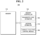
- FIG. 2 is an example block diagram for explaining the memory controller of FIG. 1 .
- a host 200 and a storage device 100 are electrically connected to each other, and the storage device 100 may operate at the request of the host 200.
- the host 200 provides the storage device 100 with a state analysis request AR of the memory installed in the storage device 100.
- the storage device 100 analyzes the state of the memory and provides the host 200 with an analysis result RSP indicating whether a garbage collection is restricted.
- Analyzing the state of memory includes determination/analysis of the fragment state of memory and the lifespan situation of the memory.
- the analysis result RSP may include, for example, “required”, “non-required”, and “restrict”.
- “Required” means that fragmentation of memory increases and garbage collection is required, and “non-required” means that fragmentation of memory is below a reference, and garbage collection is not required.
- “Restrict” means that fragmentation of memory increases, but a garbage collection execution is restricted for other reasons (e.g., a lifespan damage).
- the analysis result RSP is not restricted to the required, non-required and restrict, and may be expressed in other forms. Also, the restrict reason may be indicated as "restrict by lifespan".
- the storage device 100 provides the analysis result RSP to the host 200, at least one of the fragment state and the lifespan situation may be provided together.
- the fragment state may only indicate whether the memory is fragmented, and may also indicate fragment steps (e.g., one of steps 1 to 5).
- the fragment state may also be indicated in color and may be indicated as Yes/No or 1/0.
- the lifespan situation may also indicate only whether the lifespan situation is good/bad, and may indicate a bad step (e.g., one of steps 1 to 5).
- the lifespan situation may also be indicated in color, and may be indicated as Yes/No, 1/0.
- a host write count or a WAF Write Amplification Factor
- the host 200 may receive the analysis result RSP, and provide the garbage collection execution request ER to the storage device 100, referring to the analysis result RSP.
- the host 200 may, but is not restricted to, provide the garbage collection execution request ER only when the analysis result RSP is "required”.
- the storage device 100 may perform the garbage collection in response to the garbage collection execution request ER, and provide the result ERSP thereof to the host 200.
- the garbage collection result ERSP may be, for example, "completed” or “suspended”. "Completed” means that the garbage collection execution is completed, and "suspended” means that another request (e.g., a write) is input from the host 200 while executing the garbage collection, and the garbage collection is suspended.
- the analysis result RSP is not restricted to completed, suspended and the like, and may be expressed in other forms.
- the storage device 100 may include a memory 110 and a memory controller 150.
- the memory 110 and the memory controller 150 are electrically connected to each other, and the memory 110 operates according to the instructions of the memory controller 150 and provides the operation result to the memory controller 150.
- the memory controller 150 may be implemented using processing circuitry such as hardware including logic circuits, a hardware/software combination such as a processor executing software; or a combination thereof.
- processing circuitry such as hardware including logic circuits, a hardware/software combination such as a processor executing software; or a combination thereof.
- the processing circuitry is illustrated as being a CPU, the processing circuitry may include, but is not limited to, a CPU, an arithmetic logic unit (ALU), a digital signal processor, a microcomputer, a field programmable gate array (FPGA), a System-on-Chip (SoC) a programmable logic unit, a microprocessor, or an application-specific integrated circuit (ASIC), etc.
- ALU arithmetic logic unit
- FPGA field programmable gate array
- SoC System-on-Chip
- ASIC application-specific integrated circuit
- the processing circuitry included in the memory controller 150 may be configured as a special purpose computer through, for example, logic circuits or a processor executing software to perform the functions of a fragmented level estimator 160, a lifespan estimator 170 and a garbage collection control module 180.
- the fragmented level estimator 160 is a module that estimates/determines the fragment state of the memory 110. For example, the percentage of invalid data in the memory block may be considered. It is also possible to measure the number of invalid data in the memory block and determine whether the measured number exceeds a reference value. If the measured number exceeds the reference value, it is possible to determine that the memory block is fragmented.
- the lifespan estimator 170 is a module that estimates/determines the lifespan situation of the memory 110.
- the lifespan estimator 170 estimates how long the memory block may be used, for example, if the memory block is used by substantially the same tend (or in substantially the same way) as at the determination time point. It is determined whether the expected lifespan may satisfy a desired lifespan (or guaranteed lifespan) in this way.
- the expected lifespan estimated by the lifespan estimator 170 is 70 TBW (Total Byte Written), but the guaranteed lifespan may be 100 TBW. In such a case, the lifespan estimator 170 may determine that the expected lifespan of the memory 110 does not fulfill the desired lifespan.
- the garbage collection control module 180 is a module that controls the garbage collection operation of the memory 110. Specifically, the garbage collection control module 180 may control the memory 110 to perform the garbage collection operation at the request of the host 200. Further, the garbage collection control module 180 may generate the analysis result RSP of current state of the memory 110, on the basis of the fragment state determined by the fragmented level estimator 160 and the lifespan situation determined by the lifespan estimator 170. The analysis result RSP may be required, non-required, restrict, etc., as described above.
- the storage device 100 may be, but is not restricted to, one of an eMMC (embedded multimedia card), a UFS (universal flash storage) or a SSD (solid state drive).
- eMMC embedded multimedia card
- UFS universal flash storage
- SSD solid state drive
- FIG. 3 is a flowchart for explaining aspects of an operating method of a memory controller according to example embodiments of the present disclosure.
- the host 200 makes the state analysis request AR to the storage device 100 to check on how the memory state of the storage device 100 is, before requesting the storage device 100 to perform the garbage collection operation.
- the memory controller 150 determines the fragment state of memory when receiving the state analysis request AR from the host 200.
- the memory controller 150 determines the lifespan situation of the memory is determined.
- the memory controller 150 In operation S30, the memory controller 150 generates an analysis result RSP indicating whether the garbage collection is restricted, on the basis of the determined fragment state and lifespan situation.
- the analysis results indicating whether the garbage collection is restricted is generated, in further consideration of the host write count.
- further consideration of the host write count includes determining whether the host write count is within a restriction section. If the host write count is within the restriction section, an analysis result that restricts the garbage collection is generated, and if the host write count is outside the restriction section, an analysis result that requires garbage collection is generated.
- the size of the restriction section may change depending on the expected lifespan of memory.
- the memory controller 150 may generate an analysis result indicating that no garbage collection is required.
- the memory controller 150 provides the analysis results RSP to the host. At least one of the determined fragment state and lifespan situation may be additionally provided to the host.
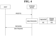
- FIGS. 4 and 5 are diagrams for explaining aspects of an operating method of the memory controller according to a first example embodiment of the present disclosure.
- FIGS. 4 and 5 explain a case where the analysis result is non-required.
- the host 200 provides the storage device 100 with a state analysis request AR of the memory.
- the storage device 100 determines the fragment state of memory in response to the state analysis request AR, and determines the lifespan situation of memory.
- the fragment state may be determined in consideration of the ratio of invalid data in the memory block.
- the lifespan situation may be determined by estimating how long the memory block may be further used, when the memory block is used by substantially the same tend as the determination time point.
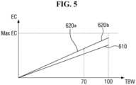
- an x-axis is a TBW (Total Byte Written), and a y-axis means an EC (erase count).
- a maximum EC EC
- the memory controller 150 may determine that the memory block has reached the end of its lifespan. It is assumed that the current state of memory is 70 TBW and the expected lifespan (guaranteed lifespan) is 100 TBW.
- Reference numeral 610 is a reference lifeline
- reference numerals 620a and 620b together mean a real lifeline of the memory block.
- the reference lifeline 610 and the real lifeline 620a, 620b take a WAF (Write Amplification Factor) into consideration.
- the memory performs an additional write operation for other reasons (e.g., garbage collection etc.), in addition to the write by write request of the host 200.
- the WAF may be defined as "an actual written amount/an amount of write requested by the host". If the WAF is 1, it means that there is no non-required write operation other than the write request of the host 200. Therefore, it is determined that, as WAF approaches 1, an efficient write operation is performed.
- a slope of the reference lifeline 610 is estimated in consideration of a reasonable WAF. Referring to the reference lifeline 610, it may be confirmed that the number of erases does not reach Max EC even if the write size reaches 100 TBW.
- a slope of a section 620a corresponding to the write size 0 to 70 TBW in the real lifeline 620a, 620b may be calculated on the basis of the way in which the memory is actually used. To explain in another way, the section 620a corresponding to the write size 0 to 70 TBW in the real lifeline 620a, 620b reflects the real WAF.
- a section 620b corresponding to the write size 70 to 100 TBW in the real lifeline 620a, 620b is estimated through, for example, extrapolation assuming a case of being used with substantially the same tend as the determination time point (that is, 70 TBW) (that is, with substantially the same slope as the slope between 0 and 70 TBW).
- the method for estimating the real lifeline 620a, 620b may use, for example, but is not limited to, a regression analysis.
- the real lifeline 620a, 620b although the real lifeline 620a, 620b has a steeper slope than the reference lifeline 610, it may be confirmed that the number of erases does not reach Max EC even if the write size reaches 100 TBW.
- the storage device 100 determines that the fragment state is non-fragmented (NO), and the lifespan situation is good (YES).
- the storage device 100 generates an analysis result RSP on the basis of the fragment state and the lifespan situation, and provides it to the host 200.
- the analysis results RSP indicate non-required of garbage collection, because the memory was not fragmented.
- FIG. 6 is a diagram for explaining aspects of an operating method of a memory controller according to a second example embodiment of the present disclosure.
- FIG. 6 explains a case where the analysis result is required.
- points different from those explained using FIGS. 4 and 5 will be mainly explained.
- the host 200 provides the storage device 100 with a state analysis request AR of the memory.
- the storage device 100 determines the fragment state of memory in response to the state analysis request AR, and determines the lifespan situation of the memory.
- the state analysis of the memory for example, the state analysis discussed with reference to FIG. 5 but with different Total Byte Written, Erase Counts and/or Write Amplification Values, the fragment state was fragmented (YES), and the lifespan situation was analyzed as good (YES).
- the storage device 100 generates an analysis result RSP on the basis of the fragment state and the lifespan situation, and provides it to the host 200.
- the analysis results RSP indicate that garbage collection is required, because the memory is fragmented and the lifespan situation is also good.
- the host 200 confirms the analysis result RSP and provides a garbage collection execution request ER.
- the storage device 100 performs the garbage collection GC.
- the storage device 100 provides the host 200 with a garbage collection result ERSP indicating that the garbage collection GC is completed.
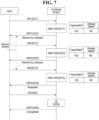
- FIGS. 7 to 9 are diagrams for explaining aspects of an operating method of the memory controller according to a third embodiment of the present disclosure.
- FIGS. 7 to 9 explain a case where the analysis result is restricted.
- points different from those explained using FIGS. 4 to 6 will be mainly explained.
- the host 200 provides the storage device 100 with a first state analysis request AR1 of the memory.
- the storage device 100 performs the first state analysis of the memory in response to the first state analysis request AR1. Specifically, the storage device 100 determines the fragment state of the memory, and determines the lifespan situation of the memory.
- an x-axis is TBW (Total Byte Written), and a y-axis means an EC (erase count). It is assumed that the current state of memory is 30 TBW and the expected lifespan (guaranteed lifespan) is 100 TBW.
- Reference numeral 610 means a reference lifeline, and reference numeral 630 means a real lifeline.
- a restriction section associated with the host write count i.e., a host write size
- the host write count means the data size that is written according to write request of the host.
- the size of the restriction section may be set in advance.
- the size of the restriction section may be 30 TBW, regardless of severity of the lifespan situation.
- the size of the restriction section may be changed depending on severity of the lifespan situation (i.e., depending on the expected lifespan). For example, if the expected lifespan is 70% of the desired lifespan (that is, if the desired lifespan is 100 TBW but the expected lifespan is 70 TBW), the size of the restriction section may be 30 TBW. Also, if the expected lifespan is 60% of the desired lifespan, the size of the restriction section is 40 TBW, which may be an increased value over 30 TBW. If the expected lifespan is 80% of the desired lifespan, the size of the restriction section is 20 TBW, which may be a decreased value from 30 TBW.
- the restriction section becomes 30 TBW to 60 TBW.
- the storage device 100 provides the first analysis result RSP1 of the memory to the host 200. Since the memory is fragmented but the lifespan situation is bad, the first analysis result RSP1 may be "restrict by lifespan".
- the host 200 receives and confirms the provision of the first analysis result RSP1 from the storage device 100, and the host 200 does not request the storage device 100 to perform the garbage collection.
- the host 200 may provide the storage device 100 with a second state analysis request AR2 of the memory.
- the storage device 100 performs the second state analysis of the memory, in response to the second state analysis request AR2 of the memory.
- the fragment state was fragmented (YES), and the lifespan situation was analyzed as bad (NO).
- the host write count is taken into further consideration. Further consideration of the host write count means determining whether the host write count is within the restriction section. As mentioned above, if the restriction section is 30TBW to 60TBW (that is, the size of the restriction section is 30TBW) and the current state of memory is 40 TBW, because 40TBW is within the restriction section, the second analysis result RSP2 may be "restrict by lifespan".
- the storage device 100 provides the second analysis result RSP2 of the memory to the host 200.
- the host 200 receives and confirms the second analysis result RSP2 from the storage device 100, and the host 200 does not request the storage device 100 to perform the garbage collection.
- the host 200 may provide the storage device 100 with a third state analysis request AR3 of the memory.
- the storage device 100 performs the third state analysis of the memory in response to the third state analysis request AR3 of the memory.
- the fragment state was fragmented (YES), and the lifespan situation was analyzed as bad (NO).
- the host write count is taken into further consideration. If the restriction section is 30 TBW to 60 TBW and the current state of memory is 65 TBW, because 65 TBW is outside the restriction section, a third analysis result RSP3 in which the garbage collection is "required" is generated.
- the storage device 100 In operation S233, the storage device 100 generates a third analysis result RSP3 of the memory indicating that garbage collection is now "required” and provides it to the host 200.
- the host 200 confirms the third analysis result RSP3, and provides a garbage collection execution request ER.
- the storage device 100 executes the garbage collection GC.
- the storage device 100 provides the host 200 with a garbage collection result ERSP indicating that the garbage collection GC is completed.
- the lifespan damage due to the garbage collection operation can be reduced.
- the slope is maintained as in reference numeral 630, and an expected lifespan becomes 70 TBW.
- the slope becomes small as in reference numeral 650, and the expected lifespan fulfills the desired lifespan 100 TBW.
- FIG. 10 is a flowchart for explaining an operating method of a memory controller according to a fourth embodiment of the present disclosure.
- a process of deriving the analysis results RSP, RSP1 to RSP3 explained using FIGS. 4 to 9 will be explained using a flowchart.
- a state analysis request is provided from the host 200.
- the memory controller 150 predicts a fragmented level (or a fragment state).
- the memory controller 150 determines whether the memory is fragmented.
- operation S451 if the memory controller 150 determines that the memory is not fragmented (No), the analysis result RSP becomes "non-required" of garbage collection, and the memory controller 150 proceeds to update the results in operation S460, discussed infra.
- the memory controller 150 determines whether the lifespan situation is stable.
- the memory controller 150 determines that the lifespan situation is unstable (Yes in operation S425), the memory controller 150 updates the trigger state . Updating of the trigger state is based on whether the host write count is within the restriction section. If the host write count is within the restriction section, the trigger state is updated to the restriction section. If the host write count is outside the restriction section, the trigger state is not updated to the restrict state.
- the memory controller 150 determines whether the updated trigger state is a restrict state.
- the memory controller 150 provides the analysis results to the host 200, where the analysis result may be non-required (S451), required (S453) or update (S460).
- FIGS. 11 and 12 are diagrams for explaining aspects of an operating method of a memory controller according to a fourth example embodiment of the present disclosure.
- an x-axis indicates a host write count HWC.
- FIG. 11 shows the state of the memory as the host write count is performed.
- a host-initiated garbage collection may be performed in a section in which the memory state is "required” (see reference numeral 511).
- the state of memory may be "non-required" during a given host write count (see reference numeral 512).
- the memory may become fragmented, but the lifespan situation of memory may be unstable, and, thus, and the memory state may be restricted "(restrict by lifespan)" (see reference numeral 513).
- the host write count is located within a desired (or, alternatively, a preset) restriction section, the memory state becomes "restrict (restrict by lifespan)".
- the size of the restriction section is shown as L0.
- the host-initiated garbage collection is performed at the section in which the memory state is "required” (see reference numeral 521). Subsequently, after the host-initiated garbage collection is completed, the memory state becomes "non-required” (see reference numeral 522). Subsequently, after a given host write count is performed without a garbage collection, the memory is fragmented, but the lifespan of memory is unstable, and, thus, the memory state may be "restricted (restrict by lifespan)" (see reference numeral 523).
- the memory state becomes "required” again (see reference numeral 524).
- the state of memory becomes "non-required” (see reference numeral 525).
- the memory was fragmented, but the lifespan of memory is unstable and the memory state may be "restricted (restrict by lifespan)" (see reference numeral 526).
- a size L1 of the restriction section 523 and a size L2 of the restriction section 526 are different from each other. As shown, the size L2 of the restriction section 526 may be larger than the size L1 of the restriction section 523.
- the size of the restriction section i.e., see the restriction section 523
- the size of the restriction section may be increased (i.e., see the restriction section 526).
- FIG. 13 is a diagram for explaining aspects of an operating method of a memory controller according to a fifth example embodiment of the present disclosure. For convenience of explanation, points different from those explained using FIG. 12 will be mainly explained.
- the state of memory may repeat required 521, non-required 522, restricted 523, required 524, non-required 525, and restricted 526.
- the host-initiated first garbage collection is performed, and at the section in which the memory state is "required 524", the host-initiated second garbage collection is performed.
- a size of a memory region 1310 at which the first garbage collection is performed may be different from a size of a memory region 1320 at which the second garbage collection is performed.
- the size of the garbage-collected memory region may be increased (that is, see the memory region 1310), and if the host write count is relatively large, the size of the garbage-collected memory region may be reduced (that is, see memory region 1320).
- FIG. 14 is a diagram for explaining aspects of an operating method of a memory controller according to a sixth embodiment of the present disclosure.
- the host 200 may provide mode control signals MCS1 and MCS2 to the memory controller 150 to perform mode conversion associated with the garbage collection.
- the host 200 may provide a first mode control signal MCS1 to the storage device 100.
- the storage device 100 is in a first mode (e.g., a performance mode) according to the first mode control signal MCS1.
- the host 200 may provide a first state analysis request AR1 to the storage device 100.
- the storage device 100 analyzes the state of the memory. For example, based on a result of the analysis, the storage device 100 may determine that the memory is fragmented and the expected lifespan of memory is expected not to fulfill the desired lifespan. Since there is a first mode in which performance is prioritized over lifespan of the memory, even if the expected lifespan of memory is determined not to fulfill the desired lifespan, the first analysis result RSP1 indicates required.
- the storage device 100 provides the first analysis result RSP1 to the host 200.
- a host-initiated garbage collection will be performed later.
- the host 200 may provide a second mode control signal MCS2 to the storage device 100.
- the storage device 100 may be in a second mode (e.g., a lifespan mode) according to the second mode control signal MCS2.
- the host 200 may provide a second state analysis request AR2 to the storage device 100.
- the storage device 100 analyzes the state of the memory. For example, the storage device 100 may determine that the memory is fragmented, and the expected lifespan of memory not to fulfill the desired lifespan. Since there is a second mode in which lifespan is prioritized over performance of the memory, even if the memory is determined to be fragmented, the second analysis result RSP2 indicates restrict (restricted by lifespan).
- FIG. 14 explains that a second mode is performed after the first mode, the second mode may be performed earlier and the first mode may be performed later.
Landscapes
- Engineering & Computer Science (AREA)
- Theoretical Computer Science (AREA)
- Physics & Mathematics (AREA)
- General Engineering & Computer Science (AREA)
- General Physics & Mathematics (AREA)
- Human Computer Interaction (AREA)
- Memory System (AREA)
- Techniques For Improving Reliability Of Storages (AREA)
Description
- Example embodiments relate to an operating method of a memory controller, an operating method of a host, and/or a storage device.
- A storage device may perform a garbage collection to improve a fragment state of a memory block by moving valid data in the memory block and erasing the memory block to secure a free block, when the invalid data in the memory block increases.
- The garbage collection may be performed at the request of a host (that is, a host-initiated garbage collection). For example, if the storage device becomes overly fragmented and a performance degradation occurs, the host may request the garbage collection on the storage device to restore performance.
- Incidentally, although a frequent garbage collection may secure a lot of free blocks and improve the performance of the storage device, because the number of times the erase operation is also performed increases, a lifespan damage to the storage device may occur.
- From document
US 2018/196619 A1 it is known a system comprising a host computer, a storage control apparatus and a storage medium. The storage control apparatus comprises a fragmentation evaluator, a rearrangement instructor and a timing selector. The timing selector pilots the fragmentation evaluator. The fragmentation evaluator pilots the rearrangement instructor. The fragmentation evaluator calculates an index value representing the degree of fragmentation and the rearrangement instructor uses the index value to determine, if the degree of fragmentation exceeds a predetermined reference value, that it is necessary to perform defragmentation by rearrangement, and executes the rearrangement. The rearrangement instructor calculates the effect obtained when data rearrangement processing is performed, using a rearrangement evaluation table based on the index value representing the degree of fragmentation; the effect of the rearrangement processing is represented as a reduction amount related to the total size of the data moved in garbage collection in the storage medium. - Object of the invention is to provide an operating method of a memory controller that inhibits (or, alternatively, prevents) excessive occurrence of host-initiated garbage collection to reduce (or, alternatively, minimize) lifespan damage to the storage device.
- The object is attained by a method of operating a memory controller according to
claim 1. Further developments of the method are defined by the dependent claims. - The and other aspects and features of the present disclosure will become more apparent by describing in detail example embodiments thereof referring to the attached drawings, in which:
-
FIG. 1 is a block diagram for explaining aspects of an operating method of a memory controller according to example embodiments of the present disclosure; -
FIG. 2 is an example block diagram for explaining the memory controller ofFIG. 1 ; -
FIG. 3 is a flowchart for explaining aspects of an operating method of the memory controller according to example embodiments of the present disclosure; -
FIGS. 4 and5 are diagrams for explaining aspects of an operating method of the memory controller according to a first example embodiment of the present disclosure; -
FIG. 6 is a diagram for explaining aspects of an operating method of the memory controller according to a second example embodiment of the present disclosure; -
FIGS. 7 to 9 are diagrams for explaining aspects of an operating method of the memory controller according to a third example embodiment of the present disclosure; -
FIG. 10 is a flowchart for explaining aspects of an operating method of the memory controller according to a fourth example embodiment of the present disclosure; -
FIGS. 11 and12 are diagrams for explaining aspects of the operating method of the memory controller according to the fourth example embodiment of the present disclosure; -
FIG. 13 is a diagram for explaining aspects of an operating method of the memory controller according to a fifth example embodiment of the present disclosure; and -
FIG. 14 is a diagram for explaining aspects of an operating method of the memory controller according to a sixth embodiment of the present disclosure. - Hereinafter, various example embodiments of the present disclosure depicting aspects of the inventive concepts will be described referring to the accompanying drawings.
-
FIG. 1 is a block diagram for explaining aspects of an operating method of a memory controller according to exemplary embodiments of the present disclosure.FIG. 2 is an example block diagram for explaining the memory controller ofFIG. 1 . - First, referring to
FIG. 1 , ahost 200 and astorage device 100 are electrically connected to each other, and thestorage device 100 may operate at the request of thehost 200. - The
host 200 provides thestorage device 100 with a state analysis request AR of the memory installed in thestorage device 100. - The
storage device 100 analyzes the state of the memory and provides thehost 200 with an analysis result RSP indicating whether a garbage collection is restricted. - Analyzing the state of memory includes determination/analysis of the fragment state of memory and the lifespan situation of the memory.
- Here, the analysis result RSP may include, for example, "required", "non-required", and "restrict". "Required" means that fragmentation of memory increases and garbage collection is required, and "non-required" means that fragmentation of memory is below a reference, and garbage collection is not required. "Restrict" means that fragmentation of memory increases, but a garbage collection execution is restricted for other reasons (e.g., a lifespan damage). The analysis result RSP is not restricted to the required, non-required and restrict, and may be expressed in other forms. Also, the restrict reason may be indicated as "restrict by lifespan".
- Also, when the
storage device 100 provides the analysis result RSP to thehost 200, at least one of the fragment state and the lifespan situation may be provided together. - Here, the fragment state may only indicate whether the memory is fragmented, and may also indicate fragment steps (e.g., one of
steps 1 to 5). The fragment state may also be indicated in color and may be indicated as Yes/No or 1/0. - Also, the lifespan situation may also indicate only whether the lifespan situation is good/bad, and may indicate a bad step (e.g., one of
steps 1 to 5). The lifespan situation may also be indicated in color, and may be indicated as Yes/No, 1/0. - Further, depending on the design, not only the fragment state and the lifespan situation, but also a host write count or a WAF (Write Amplification Factor) may be further provided to the
host 200. - The
host 200 may receive the analysis result RSP, and provide the garbage collection execution request ER to thestorage device 100, referring to the analysis result RSP. Thehost 200 may, but is not restricted to, provide the garbage collection execution request ER only when the analysis result RSP is "required". - The
storage device 100 may perform the garbage collection in response to the garbage collection execution request ER, and provide the result ERSP thereof to thehost 200. The garbage collection result ERSP may be, for example, "completed" or "suspended". "Completed" means that the garbage collection execution is completed, and "suspended" means that another request (e.g., a write) is input from thehost 200 while executing the garbage collection, and the garbage collection is suspended. The analysis result RSP is not restricted to completed, suspended and the like, and may be expressed in other forms. - Referring to
FIG. 2 , thestorage device 100 may include amemory 110 and amemory controller 150. Thememory 110 and thememory controller 150 are electrically connected to each other, and thememory 110 operates according to the instructions of thememory controller 150 and provides the operation result to thememory controller 150. - The
memory controller 150 may be implemented using processing circuitry such as hardware including logic circuits, a hardware/software combination such as a processor executing software; or a combination thereof. For example, while the processing circuitry is illustrated as being a CPU, the processing circuitry may include, but is not limited to, a CPU, an arithmetic logic unit (ALU), a digital signal processor, a microcomputer, a field programmable gate array (FPGA), a System-on-Chip (SoC) a programmable logic unit, a microprocessor, or an application-specific integrated circuit (ASIC), etc. - The processing circuitry included in the
memory controller 150 may be configured as a special purpose computer through, for example, logic circuits or a processor executing software to perform the functions of a fragmentedlevel estimator 160, alifespan estimator 170 and a garbagecollection control module 180. - The fragmented
level estimator 160 is a module that estimates/determines the fragment state of thememory 110. For example, the percentage of invalid data in the memory block may be considered. It is also possible to measure the number of invalid data in the memory block and determine whether the measured number exceeds a reference value. If the measured number exceeds the reference value, it is possible to determine that the memory block is fragmented. - The
lifespan estimator 170 is a module that estimates/determines the lifespan situation of thememory 110. Thelifespan estimator 170 estimates how long the memory block may be used, for example, if the memory block is used by substantially the same tend (or in substantially the same way) as at the determination time point. It is determined whether the expected lifespan may satisfy a desired lifespan (or guaranteed lifespan) in this way. For example, the expected lifespan estimated by thelifespan estimator 170 is 70 TBW (Total Byte Written), but the guaranteed lifespan may be 100 TBW. In such a case, thelifespan estimator 170 may determine that the expected lifespan of thememory 110 does not fulfill the desired lifespan. - The garbage
collection control module 180 is a module that controls the garbage collection operation of thememory 110. Specifically, the garbagecollection control module 180 may control thememory 110 to perform the garbage collection operation at the request of thehost 200. Further, the garbagecollection control module 180 may generate the analysis result RSP of current state of thememory 110, on the basis of the fragment state determined by thefragmented level estimator 160 and the lifespan situation determined by thelifespan estimator 170. The analysis result RSP may be required, non-required, restrict, etc., as described above. - The
storage device 100 may be, but is not restricted to, one of an eMMC (embedded multimedia card), a UFS (universal flash storage) or a SSD (solid state drive). -
FIG. 3 is a flowchart for explaining aspects of an operating method of a memory controller according to example embodiments of the present disclosure. - Referring to
FIG. 3 , thehost 200 makes the state analysis request AR to thestorage device 100 to check on how the memory state of thestorage device 100 is, before requesting thestorage device 100 to perform the garbage collection operation. - In operation S10, the
memory controller 150 determines the fragment state of memory when receiving the state analysis request AR from thehost 200. - In operation S20, the
memory controller 150 determines the lifespan situation of the memory is determined. - In operation S30, the
memory controller 150 generates an analysis result RSP indicating whether the garbage collection is restricted, on the basis of the determined fragment state and lifespan situation. - Specifically, if the memory is fragmented and the
memory controller 150 determines that the expected lifespan of memory does not fulfill the desired lifespan, the analysis results indicating whether the garbage collection is restricted is generated, in further consideration of the host write count. Here, further consideration of the host write count includes determining whether the host write count is within a restriction section. If the host write count is within the restriction section, an analysis result that restricts the garbage collection is generated, and if the host write count is outside the restriction section, an analysis result that requires garbage collection is generated. The size of the restriction section may change depending on the expected lifespan of memory. - On the other hand, if the
memory controller 150 determines that the memory is not fragmented, thememory controller 150 may generate an analysis result indicating that no garbage collection is required. - In operation S40, the
memory controller 150 provides the analysis results RSP to the host. At least one of the determined fragment state and lifespan situation may be additionally provided to the host. -
FIGS. 4 and5 are diagrams for explaining aspects of an operating method of the memory controller according to a first example embodiment of the present disclosure. In particular,FIGS. 4 and5 explain a case where the analysis result is non-required. - Referring to
FIG. 4 , in operation S210, thehost 200 provides thestorage device 100 with a state analysis request AR of the memory. - Subsequently, in operation S220, the
storage device 100 determines the fragment state of memory in response to the state analysis request AR, and determines the lifespan situation of memory. - As described above, the fragment state may be determined in consideration of the ratio of invalid data in the memory block.
- The lifespan situation may be determined by estimating how long the memory block may be further used, when the memory block is used by substantially the same tend as the determination time point.
- Specifically, referring to
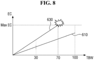
FIG. 5 , an x-axis is a TBW (Total Byte Written), and a y-axis means an EC (erase count). When the number of erases of the memory block reaches a maximum EC (Max EC), thememory controller 150 may determine that the memory block has reached the end of its lifespan. It is assumed that the current state of memory is 70 TBW and the expected lifespan (guaranteed lifespan) is 100 TBW. -
Reference numeral 610 is a reference lifeline, andreference numerals - The
reference lifeline 610 and thereal lifeline host 200. The WAF may be defined as "an actual written amount/an amount of write requested by the host". If the WAF is 1, it means that there is no non-required write operation other than the write request of thehost 200. Therefore, it is determined that, as WAF approaches 1, an efficient write operation is performed. - A slope of the
reference lifeline 610 is estimated in consideration of a reasonable WAF. Referring to thereference lifeline 610, it may be confirmed that the number of erases does not reach Max EC even if the write size reaches 100 TBW. - A slope of a
section 620a corresponding to the write size 0 to 70 TBW in thereal lifeline section 620a corresponding to the write size 0 to 70 TBW in thereal lifeline - Also, a
section 620b corresponding to thewrite size 70 to 100 TBW in thereal lifeline - The method for estimating the
real lifeline - Referring to the
real lifeline real lifeline reference lifeline 610, it may be confirmed that the number of erases does not reach Max EC even if the write size reaches 100 TBW. - Referring again to
FIG. 4 , based on the data generated with reference toFIG. 5 as a result in which thestorage device 100 performs the state analysis of the memory at the request of the host 20, thestorage device 100 determines that the fragment state is non-fragmented (NO), and the lifespan situation is good (YES). - Subsequently, in operation S230, the
storage device 100 generates an analysis result RSP on the basis of the fragment state and the lifespan situation, and provides it to thehost 200. The analysis results RSP indicate non-required of garbage collection, because the memory was not fragmented. -
FIG. 6 is a diagram for explaining aspects of an operating method of a memory controller according to a second example embodiment of the present disclosure. In particular,FIG. 6 explains a case where the analysis result is required. For convenience of explanation, points different from those explained usingFIGS. 4 and5 will be mainly explained. - Referring to
FIG. 6 , in operation S210, thehost 200 provides thestorage device 100 with a state analysis request AR of the memory. - Subsequently, in operation S220, the
storage device 100 determines the fragment state of memory in response to the state analysis request AR, and determines the lifespan situation of the memory. As a result of the state analysis of the memory, for example, the state analysis discussed with reference toFIG. 5 but with different Total Byte Written, Erase Counts and/or Write Amplification Values, the fragment state was fragmented (YES), and the lifespan situation was analyzed as good (YES). - Subsequently, in operation S230, the
storage device 100 generates an analysis result RSP on the basis of the fragment state and the lifespan situation, and provides it to thehost 200. The analysis results RSP indicate that garbage collection is required, because the memory is fragmented and the lifespan situation is also good. - Subsequently, in operation S240, the
host 200 confirms the analysis result RSP and provides a garbage collection execution request ER. - Subsequently, in operation S250, the
storage device 100 performs the garbage collection GC. - In operation S260, the
storage device 100 provides thehost 200 with a garbage collection result ERSP indicating that the garbage collection GC is completed. -
FIGS. 7 to 9 are diagrams for explaining aspects of an operating method of the memory controller according to a third embodiment of the present disclosure. In particular,FIGS. 7 to 9 explain a case where the analysis result is restricted. For convenience of explanation, points different from those explained usingFIGS. 4 to 6 will be mainly explained. - Referring to
FIG. 7 , in operation S211, thehost 200 provides thestorage device 100 with a first state analysis request AR1 of the memory. - Subsequently, in operation S221, the
storage device 100 performs the first state analysis of the memory in response to the first state analysis request AR1. Specifically, thestorage device 100 determines the fragment state of the memory, and determines the lifespan situation of the memory. - As a result of the state analysis of the memory, the fragment state was fragmented (YES), and the lifespan situation was analyzed as bad (NO). Here, the lifespan situation analysis will be specifically explained referring to
FIG. 8 . Referring toFIG. 8 , an x-axis is TBW (Total Byte Written), and a y-axis means an EC (erase count). It is assumed that the current state of memory is 30 TBW and the expected lifespan (guaranteed lifespan) is 100 TBW.Reference numeral 610 means a reference lifeline, andreference numeral 630 means a real lifeline. - If a slope after the determination time point (current state) (that is, after the
write size 30 TBW) is the same as a slope before the determination time point (that is, the write size 0 to 30 TBW) at thereal lifespan line 630, it is expected that the expected lifespan (guaranteed lifespan) of memory is not fulfilled. That is, because the slope of thereal lifeline 630 is sufficiently steep, the number of erases reaches Max EC at about 70 TBW (before 100 TBW which is the expected lifespan). Therefore, thememory controller 150 determines the lifespan situation as bad (NO). - If the memory is fragmented and it is determined that the expected lifespan of memory does not fulfill the desired lifespan, a restriction section associated with the host write count (i.e., a host write size) is set. The host write count (i.e., host write size) means the data size that is written according to write request of the host.
- The size of the restriction section may be set in advance. The size of the restriction section may be 30 TBW, regardless of severity of the lifespan situation.
- Also, the size of the restriction section may be changed depending on severity of the lifespan situation (i.e., depending on the expected lifespan). For example, if the expected lifespan is 70% of the desired lifespan (that is, if the desired lifespan is 100 TBW but the expected lifespan is 70 TBW), the size of the restriction section may be 30 TBW. Also, if the expected lifespan is 60% of the desired lifespan, the size of the restriction section is 40 TBW, which may be an increased value over 30 TBW. If the expected lifespan is 80% of the desired lifespan, the size of the restriction section is 20 TBW, which may be a decreased value from 30 TBW.
- For example, if the size of the restriction section is set to 30 TBW, because the determination time point is 30 TBW, the restriction section becomes 30 TBW to 60 TBW.
- In operation S231, the
storage device 100 provides the first analysis result RSP1 of the memory to thehost 200. Since the memory is fragmented but the lifespan situation is bad, the first analysis result RSP1 may be "restrict by lifespan". - The
host 200 receives and confirms the provision of the first analysis result RSP1 from thestorage device 100, and thehost 200 does not request thestorage device 100 to perform the garbage collection. - Subsequently, after passage of some time, in operation S212, the
host 200 may provide thestorage device 100 with a second state analysis request AR2 of the memory. - In operation S222, the
storage device 100 performs the second state analysis of the memory, in response to the second state analysis request AR2 of the memory. As a result of state analysis of the memory, the fragment state was fragmented (YES), and the lifespan situation was analyzed as bad (NO). - If the memory is fragmented and it is determined that the expected lifespan of memory does not fulfill the desired lifespan, the host write count is taken into further consideration. Further consideration of the host write count means determining whether the host write count is within the restriction section. As mentioned above, if the restriction section is 30TBW to 60TBW (that is, the size of the restriction section is 30TBW) and the current state of memory is 40 TBW, because 40TBW is within the restriction section, the second analysis result RSP2 may be "restrict by lifespan".
- In operation S232, the
storage device 100 provides the second analysis result RSP2 of the memory to thehost 200. - The
host 200 receives and confirms the second analysis result RSP2 from thestorage device 100, and thehost 200 does not request thestorage device 100 to perform the garbage collection. - Subsequently, after passage of additional time, in operation S213, the
host 200 may provide thestorage device 100 with a third state analysis request AR3 of the memory. - In operation S223, the
storage device 100 performs the third state analysis of the memory in response to the third state analysis request AR3 of the memory. As a result of the state analysis of the memory, the fragment state was fragmented (YES), and the lifespan situation was analyzed as bad (NO). - Since the memory was fragmented and it was determined that the expected lifespan of memory does not fulfill the desired lifespan, the host write count is taken into further consideration. If the restriction section is 30 TBW to 60 TBW and the current state of memory is 65 TBW, because 65 TBW is outside the restriction section, a third analysis result RSP3 in which the garbage collection is "required" is generated.
- In operation S233, the
storage device 100 generates a third analysis result RSP3 of the memory indicating that garbage collection is now "required" and provides it to thehost 200. - In operation S240, the
host 200 confirms the third analysis result RSP3, and provides a garbage collection execution request ER. - In operation S250, the
storage device 100 executes the garbage collection GC. - In operation S260, the
storage device 100 provides thehost 200 with a garbage collection result ERSP indicating that the garbage collection GC is completed. - According to the operating method of the memory controller according to the third example embodiment of the present disclosure, because the garbage collection operation is restricted while the host write count is within the restriction section, the lifespan damage due to the garbage collection operation can be reduced.
- For example, as shown in
FIG. 9 , if the garbage collection operation is not restricted, the slope is maintained as inreference numeral 630, and an expected lifespan becomes 70 TBW. On the other hand, it may be seen that, by restricting the garbage collection operation during the restriction section, the slope becomes small as inreference numeral 650, and the expected lifespan fulfills the desiredlifespan 100 TBW. -
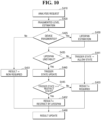
FIG. 10 is a flowchart for explaining an operating method of a memory controller according to a fourth embodiment of the present disclosure. A process of deriving the analysis results RSP, RSP1 to RSP3 explained usingFIGS. 4 to 9 will be explained using a flowchart. - Referring to
FIG. 10 , in operation S410, a state analysis request is provided from thehost 200. - In operation S420, the
memory controller 150 predicts a fragmented level (or a fragment state). - In operation S425, the
memory controller 150 determines whether the memory is fragmented. - In operation S451, if the
memory controller 150 determines that the memory is not fragmented (No), the analysis result RSP becomes "non-required" of garbage collection, and thememory controller 150 proceeds to update the results in operation S460, discussed infra. - On the other hand, in operation S430, if the
memory controller 150 determines that the memory is to be fragmented (Yes), the lifespan situation of the memory (that is, an expected lifespan) is predicted. - In operation S435, the
memory controller 150 determines whether the lifespan situation is stable. - In operation S441, when the
memory controller 150 determines that the lifespan situation is stable (No in operation S435), a trigger state trigger state is changed to an allow state, and thereafter, in operation S453, thememory controller 150 sets the analysis result RSP to indicate "required" of the garbage collection. - On the other hand, in operation S440, when the
memory controller 150 determines that the lifespan situation is unstable (Yes in operation S425), thememory controller 150 updates the trigger state . Updating of the trigger state is based on whether the host write count is within the restriction section. If the host write count is within the restriction section, the trigger state is updated to the restriction section. If the host write count is outside the restriction section, the trigger state is not updated to the restrict state. - In operation S445, the
memory controller 150 determines whether the updated trigger state is a restrict state. - In operation S453, if the trigger state is not a restrict state (No in operation S445), the
memory controller 150 updates the analysis result RSP to indicate "required" of the garbage collection. - In contrast, in operation S452, if the trigger state is the restrict state (Yes in operation S445), the
memory controller 150 updates the analysis result RSP to indicate "restrict by lifespan". - In operation S460, the
memory controller 150 provides the analysis results to thehost 200, where the analysis result may be non-required (S451), required (S453) or update (S460). -
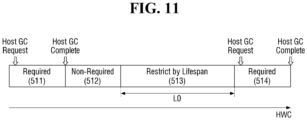
FIGS. 11 and12 are diagrams for explaining aspects of an operating method of a memory controller according to a fourth example embodiment of the present disclosure. - Referring to
FIG. 11 , an x-axis indicates a host write count HWC.FIG. 11 shows the state of the memory as the host write count is performed. - A host-initiated garbage collection may be performed in a section in which the memory state is "required" (see reference numeral 511).
- Subsequently, after the host-initiated garbage collection is completed, the state of memory may be "non-required" during a given host write count (see reference numeral 512).
- Subsequently, after a given host write count is performed without a garbage collection, the memory may become fragmented, but the lifespan situation of memory may be unstable, and, thus, and the memory state may be restricted "(restrict by lifespan)" (see reference numeral 513). As explained using
FIG. 7 , when the host write count is located within a desired (or, alternatively, a preset) restriction section, the memory state becomes "restrict (restrict by lifespan)". The size of the restriction section is shown as L0. - Subsequently, if the host write count exceeds the desired (or, alternatively, the preset) restriction section L0, the memory state becomes "required" again (see reference numeral 514).
- Referring to
FIG. 12 , the host-initiated garbage collection is performed at the section in which the memory state is "required" (see reference numeral 521). Subsequently, after the host-initiated garbage collection is completed, the memory state becomes "non-required" (see reference numeral 522). Subsequently, after a given host write count is performed without a garbage collection, the memory is fragmented, but the lifespan of memory is unstable, and, thus, the memory state may be "restricted (restrict by lifespan)" (see reference numeral 523). - Subsequently, if the host write count exceeds a desired (or, alternatively, a preset) restriction section L0, the memory state becomes "required" again (see reference numeral 524). Subsequently, after the host-initiated garbage collection is completed, the state of memory becomes "non-required" (see reference numeral 525). Subsequently, after a given host write count is performed without a garbage collection, the memory was fragmented, but the lifespan of memory is unstable and the memory state may be "restricted (restrict by lifespan)" (see reference numeral 526).
- On the other hand, a size L1 of the
restriction section 523 and a size L2 of therestriction section 526 are different from each other. As shown, the size L2 of therestriction section 526 may be larger than the size L1 of therestriction section 523. - That is, as the host write count increases, the lifespan situation of memory may gradually worsen. Therefore, if the host write count is relatively low, the size of the restriction section (i.e., see the restriction section 523) may be decreased, and if the host write count is relatively large, the size of the restriction section may be increased (i.e., see the restriction section 526). When increasing the size of the restriction section, it is possible to reduce an occurrence frequency of host-initiated garbage collection. Therefore, the lifespan damage of the memory due to garbage collection can be reduced.
-
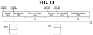
FIG. 13 is a diagram for explaining aspects of an operating method of a memory controller according to a fifth example embodiment of the present disclosure. For convenience of explanation, points different from those explained usingFIG. 12 will be mainly explained. - Referring to
FIG. 13 , as the host write count HWC increases, the state of memory may repeat required 521, non-required 522, restricted 523, required 524, non-required 525, and restricted 526. At the section in which the memory state is "required 521", the host-initiated first garbage collection is performed, and at the section in which the memory state is "required 524", the host-initiated second garbage collection is performed. - On the other hand, a size of a
memory region 1310 at which the first garbage collection is performed may be different from a size of amemory region 1320 at which the second garbage collection is performed. - As the host write count increases, the lifespan situation of memory may gradually worsen. Therefore, if the host write count is relatively low, the size of the garbage-collected memory region may be increased (that is, see the memory region 1310), and if the host write count is relatively large, the size of the garbage-collected memory region may be reduced (that is, see memory region 1320). By reducing the size of the garbage-collected memory region, it is possible to reduce the memory region in which lifespan is impaired.
-
FIG. 14 is a diagram for explaining aspects of an operating method of a memory controller according to a sixth embodiment of the present disclosure. - Referring to
FIG. 14 , thehost 200 may provide mode control signals MCS1 and MCS2 to thememory controller 150 to perform mode conversion associated with the garbage collection. - Specifically, in operation S270, the
host 200 may provide a first mode control signal MCS1 to thestorage device 100. Thestorage device 100 is in a first mode (e.g., a performance mode) according to the first mode control signal MCS1. - Subsequently, in operation S271, the
host 200 may provide a first state analysis request AR1 to thestorage device 100. - In response thereto, in operation S272, the
storage device 100 analyzes the state of the memory. For example, based on a result of the analysis, thestorage device 100 may determine that the memory is fragmented and the expected lifespan of memory is expected not to fulfill the desired lifespan. Since there is a first mode in which performance is prioritized over lifespan of the memory, even if the expected lifespan of memory is determined not to fulfill the desired lifespan, the first analysis result RSP1 indicates required. - In operation S273, the
storage device 100 provides the first analysis result RSP1 to thehost 200. Although not shown separately, a host-initiated garbage collection will be performed later. - In operation S272, the
host 200 may provide a second mode control signal MCS2 to thestorage device 100. Thestorage device 100 may be in a second mode (e.g., a lifespan mode) according to the second mode control signal MCS2. - Subsequently, in operation S276, the
host 200 may provide a second state analysis request AR2 to thestorage device 100. - In response thereto, in operation S277, the
storage device 100 analyzes the state of the memory. For example, thestorage device 100 may determine that the memory is fragmented, and the expected lifespan of memory not to fulfill the desired lifespan. Since there is a second mode in which lifespan is prioritized over performance of the memory, even if the memory is determined to be fragmented, the second analysis result RSP2 indicates restrict (restricted by lifespan). - Although
FIG. 14 explains that a second mode is performed after the first mode, the second mode may be performed earlier and the first mode may be performed later. - While the inventive concepts have been described with reference to exemplary embodiments, it will be apparent to those skilled in the art that various changes and modifications may be made without departing from the scope of the appended claims.
Claims (8)
- A method of operating a memory controller, the method comprising:receiving (S210; S410) a state analysis request of a memory (110) from a host (200);determining (S10; S220; S425) a fragment state of the memory (110);determining (S20; S220; S430) a lifespan situation of the memory (110);generating (S30; S230) an analysis result indicating whether a garbage collection is restricted, based on the fragment state and the lifespan situation; andproviding (S40; S230; S460) the analysis result to the host (200),wherein generating (S30; S230) the analysis result comprises:
determining (S445) whether the garbage collection is restricted based on a host write count, in response to the memory (110) being fragmented and the lifespan situation being such that an expected lifespan of the memory (110) is determined not to fulfill a desired lifespan,wherein the determining (S445) whether the garbage collection is restricted based on the host write count comprises:
determining whether the host write count is within a restriction section, andwherein generating (S30; S230) the analysis result further comprises:generating (S452) the analysis result such that the analysis result indicates that the garbage collection is restricted, in response to the host write count being within the restriction section, andgenerating (S453) the analysis result such that the analysis result indicates that the garbage collection is required, in response to the host write count being outside the restriction section. - The method of claim 1, further comprising:
adjusting a size of the restriction section based on the expected lifespan of the memory (110). - The method of claim 1, wherein generating the analysis result (S30; S230) comprises:
generating (S451) the analysis result that the analysis result indicates the garbage collection is not required, in response to the fragment state of the memory (110) being below a fragmentation threshold. - The method of claim 1, further comprising:receiving (S240) a garbage collection execution request from the host (200), in response to providing (S40; 230) the analysis result to the host (200);performing (S250) a garbage collection operation on a garbage-collected memory region of the memory (110), in response to the garbage collection execution request; andadjusting a size of the garbage-collected memory region based on the lifespan situation of the memory (110).
- The method of claim 1, further comprising:
providing the host (200) with the fragment state and the lifespan situation. - The method of claim 1, wherein the determining the lifespan situation comprises:
calculating an expected lifespan based on a Write Amplification Factor. - The method of claim 1, further comprising:
receiving (S270; 275) a mode control signal from the host (200), and wherein the generating (S30; S230) the analysis result comprises:generating (S276) the analysis result based on the fragment state and the lifespan situation, in response to the mode control signal indicating a first mode, andgenerating (273) the analysis result based on the fragment state without consideration of the lifespan situation, in response to the mode control signal indicating a second mode. - The method of claim 1, wherein the memory (110) is included in one of an embedded multimedia card, a universal flash storage, or a solid state drive.
Applications Claiming Priority (1)
| Application Number | Priority Date | Filing Date | Title |
|---|---|---|---|
| KR1020200075084A KR102958706B1 (en) | 2020-06-19 | 2020-06-19 | Operating method of memory controller, operating method of host and storage device |
Publications (2)
| Publication Number | Publication Date |
|---|---|
| EP3926478A1 EP3926478A1 (en) | 2021-12-22 |
| EP3926478B1 true EP3926478B1 (en) | 2023-06-07 |
Family
ID=74797795
Family Applications (1)
| Application Number | Title | Priority Date | Filing Date |
|---|---|---|---|
| EP21159564.0A Active EP3926478B1 (en) | 2020-06-19 | 2021-02-26 | Operating method of memory controller, operating method of host and storage device |
Country Status (4)
| Country | Link |
|---|---|
| US (1) | US11614882B2 (en) |
| EP (1) | EP3926478B1 (en) |
| KR (1) | KR102958706B1 (en) |
| CN (1) | CN113821454B (en) |
Families Citing this family (5)
| Publication number | Priority date | Publication date | Assignee | Title |
|---|---|---|---|---|
| KR20230071214A (en) | 2021-11-16 | 2023-05-23 | 주식회사 엘지에너지솔루션 | Battery management apparatus and method for controlling battery |
| US11995342B2 (en) * | 2021-12-22 | 2024-05-28 | Micron Technology, Inc. | Host initiated garbage collection |
| US12112044B2 (en) * | 2022-05-12 | 2024-10-08 | SanDisk Technologies, Inc. | Recognition and report of expected write amplification violation |
| KR20230168908A (en) * | 2022-06-08 | 2023-12-15 | 에스케이하이닉스 주식회사 | Computing system and operating method thereof |
| US11972149B2 (en) * | 2022-07-27 | 2024-04-30 | Western Digital Technologies, Inc. | Storage system and method for optimizing host-activated defragmentation and proactive garbage collection processes |
Family Cites Families (28)
| Publication number | Priority date | Publication date | Assignee | Title |
|---|---|---|---|---|
| US6308185B1 (en) * | 1998-03-06 | 2001-10-23 | Sun Microsystems, Inc. | Methods and apparatus for generational dynamic management of computer memory |
| US7653778B2 (en) | 2006-05-08 | 2010-01-26 | Siliconsystems, Inc. | Systems and methods for measuring the useful life of solid-state storage devices |
| TWI387962B (en) * | 2007-05-28 | 2013-03-01 | Sandisk Il Ltd | System and method for removable mass storage device and computer readable medium for storing information |
| US8301672B2 (en) * | 2008-09-22 | 2012-10-30 | Advanced Micro Devices, Inc. | GPU assisted garbage collection |
| US8364886B2 (en) * | 2010-01-26 | 2013-01-29 | Seagate Technology Llc | Verifying whether metadata identifies a most current version of stored data in a memory space |
| US20120011319A1 (en) * | 2010-07-01 | 2012-01-12 | Infinidat Ltd. | Mass storage system and method of operating thereof |
| KR102053865B1 (en) | 2013-03-15 | 2019-12-09 | 삼성전자주식회사 | Host-driven garbage collection method and system performing the method |
| KR20150058927A (en) * | 2013-11-21 | 2015-05-29 | 삼성전자주식회사 | Technique for controlling write speed of nonvolatile memory |
| KR20150106778A (en) * | 2014-03-12 | 2015-09-22 | 삼성전자주식회사 | Memory Device and Controlling Method of Memory Device |
| KR20150106777A (en) | 2014-03-12 | 2015-09-22 | 삼성전자주식회사 | Flash memory device and controlling method of flash memory device |
| US9348520B2 (en) * | 2014-03-24 | 2016-05-24 | Western Digital Technologies, Inc. | Lifetime extension of non-volatile semiconductor memory for data storage device |
| US9564212B2 (en) * | 2014-05-06 | 2017-02-07 | Western Digital Technologies, Inc. | Solid-state memory corruption mitigation |
| US9600409B2 (en) * | 2014-08-29 | 2017-03-21 | EMC IP Holding Company LLC | Method and system for garbage collection in a storage system based on longevity of stored data |
| US10409526B2 (en) * | 2014-12-17 | 2019-09-10 | Violin Systems Llc | Adaptive garbage collection |
| KR101631409B1 (en) | 2015-03-06 | 2016-06-24 | 한양대학교 산학협력단 | Storage apparatus including drive controller, the drive controller for performing garbage collection perform method |
| US9778878B2 (en) | 2015-04-22 | 2017-10-03 | Sandisk Technologies Llc | Method and system for limiting write command execution |
| WO2016175028A1 (en) * | 2015-04-28 | 2016-11-03 | 日本電気株式会社 | Information processing system, storage control device, storage control method, and storage control program |
| JP6691669B2 (en) * | 2015-07-06 | 2020-05-13 | 日本電気株式会社 | Information processing system, storage control device, storage control method, and storage control program |
| US10198194B2 (en) | 2015-08-24 | 2019-02-05 | Pure Storage, Inc. | Placing data within a storage device of a flash array |
| US9940040B2 (en) * | 2015-08-26 | 2018-04-10 | Toshiba Memory Corporation | Systems, solid-state mass storage devices, and methods for host-assisted garbage collection |
| US10185658B2 (en) * | 2016-02-23 | 2019-01-22 | Sandisk Technologies Llc | Efficient implementation of optimized host-based garbage collection strategies using xcopy and multiple logical stripes |
| US10534716B2 (en) | 2016-07-13 | 2020-01-14 | Seagate Technology Llc | Limiting access operations in a data storage device |
| US11188456B2 (en) * | 2017-03-21 | 2021-11-30 | Western Digital Technologies Inc. | Storage system and method for predictive block allocation for efficient garbage collection |
| US11537513B2 (en) * | 2017-12-11 | 2022-12-27 | SK Hynix Inc. | Apparatus and method for operating garbage collection using host idle |
| JP6901427B2 (en) * | 2018-03-27 | 2021-07-14 | キオクシア株式会社 | How storage devices, computer systems and storage devices work |
| KR20190128392A (en) | 2018-05-08 | 2019-11-18 | 에스케이하이닉스 주식회사 | Memory system and operation method thereof |
| KR102620731B1 (en) | 2018-09-27 | 2024-01-05 | 에스케이하이닉스 주식회사 | Memory system and operating method thereof |
| KR102167457B1 (en) | 2018-12-10 | 2020-10-19 | 아우토리브 디벨롭먼트 아베 | Airbag apparatus of vehicle |
-
2020
- 2020-06-19 KR KR1020200075084A patent/KR102958706B1/en active Active
-
2021
- 2021-02-26 EP EP21159564.0A patent/EP3926478B1/en active Active
- 2021-03-08 US US17/194,588 patent/US11614882B2/en active Active
- 2021-05-18 CN CN202110540462.2A patent/CN113821454B/en active Active
Also Published As
| Publication number | Publication date |
|---|---|
| CN113821454A (en) | 2021-12-21 |
| US20210397367A1 (en) | 2021-12-23 |
| US11614882B2 (en) | 2023-03-28 |
| EP3926478A1 (en) | 2021-12-22 |
| KR102958706B1 (en) | 2026-04-28 |
| CN113821454B (en) | 2026-04-14 |
| KR20210157157A (en) | 2021-12-28 |
Similar Documents
| Publication | Publication Date | Title |
|---|---|---|
| EP3926478A1 (en) | Operating method of memory controller, operating method of host and storage device | |
| US8799561B2 (en) | Valid page threshold based garbage collection for solid state drive | |
| US10552315B2 (en) | Data processing method and apparatus, and flash device | |
| US20250123748A1 (en) | Dynamic processing of storage command based on internal operations of storage system | |
| CN111742291B (en) | Method and system for user space storage I/O stack with user space flash translation layer | |
| US10133679B2 (en) | Read cache management method and apparatus based on solid state drive | |
| US8117415B2 (en) | Storage device estimating a completion time for a storage operation | |
| US9569352B2 (en) | Storage module and method for regulating garbage collection operations based on write activity of a host | |
| US10281970B2 (en) | Control device, system, and computer program product | |
| CN111427510B (en) | Data storage system and method for optimized scheduling of background management operations | |
| US8117505B2 (en) | Resource exhaustion prediction, detection, diagnosis and correction | |
| US20160378656A1 (en) | Storage device, cache-write control method, and cache-write control program | |
| US20190079697A1 (en) | Storage device | |
| EP3564826A1 (en) | File processing method and server | |
| CN103455319A (en) | Data storage device and flash memory control method | |
| CN108139904A (en) | write command filter | |
| TW201800949A (en) | System and methods for increasing useful lifetime of a flash memory device | |
| US20160342540A1 (en) | Low latency memory and bus frequency scaling based upon hardware monitoring | |
| CN118550466A (en) | SSD writing performance regulation and control method, device, equipment and medium | |
| KR102075358B1 (en) | Data storage device and operating method thereof | |
| US12050796B2 (en) | Managing deduplication operations based on a likelihood of duplicability | |
| CN108292263B (en) | Information processing apparatus and information processing method | |
| JP2002318698A (en) | Process control device and control method | |
| CN120233952B (en) | Data processing method and device, storage medium and electronic equipment | |
| CN120233957B (en) | Memory optimization method, training device, training equipment and training vehicle for model |
Legal Events
| Date | Code | Title | Description |
|---|---|---|---|
| PUAI | Public reference made under article 153(3) epc to a published international application that has entered the european phase |
Free format text: ORIGINAL CODE: 0009012 |
|
| STAA | Information on the status of an ep patent application or granted ep patent |
Free format text: STATUS: EXAMINATION IS IN PROGRESS |
|
| 17P | Request for examination filed |
Effective date: 20210226 |
|
| AK | Designated contracting states |
Kind code of ref document: A1 Designated state(s): AL AT BE BG CH CY CZ DE DK EE ES FI FR GB GR HR HU IE IS IT LI LT LU LV MC MK MT NL NO PL PT RO RS SE SI SK SM TR |
|
| B565 | Issuance of search results under rule 164(2) epc |
Effective date: 20210823 |
|
| GRAP | Despatch of communication of intention to grant a patent |
Free format text: ORIGINAL CODE: EPIDOSNIGR1 |
|
| STAA | Information on the status of an ep patent application or granted ep patent |
Free format text: STATUS: GRANT OF PATENT IS INTENDED |
|
| RIC1 | Information provided on ipc code assigned before grant |
Ipc: G06F 12/02 19850101AFI20230105BHEP |
|
| INTG | Intention to grant announced |
Effective date: 20230130 |
|
| GRAS | Grant fee paid |
Free format text: ORIGINAL CODE: EPIDOSNIGR3 |
|
| GRAA | (expected) grant |
Free format text: ORIGINAL CODE: 0009210 |
|
| STAA | Information on the status of an ep patent application or granted ep patent |
Free format text: STATUS: THE PATENT HAS BEEN GRANTED |
|
| AK | Designated contracting states |
Kind code of ref document: B1 Designated state(s): AL AT BE BG CH CY CZ DE DK EE ES FI FR GB GR HR HU IE IS IT LI LT LU LV MC MK MT NL NO PL PT RO RS SE SI SK SM TR |
|
| REG | Reference to a national code |
Ref country code: GB Ref legal event code: FG4D |
|
| REG | Reference to a national code |
Ref country code: CH Ref legal event code: EP Ref country code: AT Ref legal event code: REF Ref document number: 1577118 Country of ref document: AT Kind code of ref document: T Effective date: 20230615 |
|
| REG | Reference to a national code |
Ref country code: DE Ref legal event code: R096 Ref document number: 602021002616 Country of ref document: DE |
|
| P01 | Opt-out of the competence of the unified patent court (upc) registered |
Effective date: 20230520 |
|
| REG | Reference to a national code |
Ref country code: LT Ref legal event code: MG9D |
|
| REG | Reference to a national code |
Ref country code: NL Ref legal event code: MP Effective date: 20230607 |
|
| PG25 | Lapsed in a contracting state [announced via postgrant information from national office to epo] |
Ref country code: SE Free format text: LAPSE BECAUSE OF FAILURE TO SUBMIT A TRANSLATION OF THE DESCRIPTION OR TO PAY THE FEE WITHIN THE PRESCRIBED TIME-LIMIT Effective date: 20230607 Ref country code: NO Free format text: LAPSE BECAUSE OF FAILURE TO SUBMIT A TRANSLATION OF THE DESCRIPTION OR TO PAY THE FEE WITHIN THE PRESCRIBED TIME-LIMIT Effective date: 20230907 Ref country code: ES Free format text: LAPSE BECAUSE OF FAILURE TO SUBMIT A TRANSLATION OF THE DESCRIPTION OR TO PAY THE FEE WITHIN THE PRESCRIBED TIME-LIMIT Effective date: 20230607 |
|
| REG | Reference to a national code |
Ref country code: AT Ref legal event code: MK05 Ref document number: 1577118 Country of ref document: AT Kind code of ref document: T Effective date: 20230607 |
|
| PG25 | Lapsed in a contracting state [announced via postgrant information from national office to epo] |
Ref country code: RS Free format text: LAPSE BECAUSE OF FAILURE TO SUBMIT A TRANSLATION OF THE DESCRIPTION OR TO PAY THE FEE WITHIN THE PRESCRIBED TIME-LIMIT Effective date: 20230607 Ref country code: NL Free format text: LAPSE BECAUSE OF FAILURE TO SUBMIT A TRANSLATION OF THE DESCRIPTION OR TO PAY THE FEE WITHIN THE PRESCRIBED TIME-LIMIT Effective date: 20230607 Ref country code: LV Free format text: LAPSE BECAUSE OF FAILURE TO SUBMIT A TRANSLATION OF THE DESCRIPTION OR TO PAY THE FEE WITHIN THE PRESCRIBED TIME-LIMIT Effective date: 20230607 Ref country code: LT Free format text: LAPSE BECAUSE OF FAILURE TO SUBMIT A TRANSLATION OF THE DESCRIPTION OR TO PAY THE FEE WITHIN THE PRESCRIBED TIME-LIMIT Effective date: 20230607 Ref country code: HR Free format text: LAPSE BECAUSE OF FAILURE TO SUBMIT A TRANSLATION OF THE DESCRIPTION OR TO PAY THE FEE WITHIN THE PRESCRIBED TIME-LIMIT Effective date: 20230607 Ref country code: GR Free format text: LAPSE BECAUSE OF FAILURE TO SUBMIT A TRANSLATION OF THE DESCRIPTION OR TO PAY THE FEE WITHIN THE PRESCRIBED TIME-LIMIT Effective date: 20230908 |
|
| PG25 | Lapsed in a contracting state [announced via postgrant information from national office to epo] |
Ref country code: FI Free format text: LAPSE BECAUSE OF FAILURE TO SUBMIT A TRANSLATION OF THE DESCRIPTION OR TO PAY THE FEE WITHIN THE PRESCRIBED TIME-LIMIT Effective date: 20230607 |
|
| PG25 | Lapsed in a contracting state [announced via postgrant information from national office to epo] |
Ref country code: SK Free format text: LAPSE BECAUSE OF FAILURE TO SUBMIT A TRANSLATION OF THE DESCRIPTION OR TO PAY THE FEE WITHIN THE PRESCRIBED TIME-LIMIT Effective date: 20230607 |
|
| PG25 | Lapsed in a contracting state [announced via postgrant information from national office to epo] |
Ref country code: IS Free format text: LAPSE BECAUSE OF FAILURE TO SUBMIT A TRANSLATION OF THE DESCRIPTION OR TO PAY THE FEE WITHIN THE PRESCRIBED TIME-LIMIT Effective date: 20231007 |
|
| PG25 | Lapsed in a contracting state [announced via postgrant information from national office to epo] |
Ref country code: SM Free format text: LAPSE BECAUSE OF FAILURE TO SUBMIT A TRANSLATION OF THE DESCRIPTION OR TO PAY THE FEE WITHIN THE PRESCRIBED TIME-LIMIT Effective date: 20230607 Ref country code: SK Free format text: LAPSE BECAUSE OF FAILURE TO SUBMIT A TRANSLATION OF THE DESCRIPTION OR TO PAY THE FEE WITHIN THE PRESCRIBED TIME-LIMIT Effective date: 20230607 Ref country code: RO Free format text: LAPSE BECAUSE OF FAILURE TO SUBMIT A TRANSLATION OF THE DESCRIPTION OR TO PAY THE FEE WITHIN THE PRESCRIBED TIME-LIMIT Effective date: 20230607 Ref country code: PT Free format text: LAPSE BECAUSE OF FAILURE TO SUBMIT A TRANSLATION OF THE DESCRIPTION OR TO PAY THE FEE WITHIN THE PRESCRIBED TIME-LIMIT Effective date: 20231009 Ref country code: IS Free format text: LAPSE BECAUSE OF FAILURE TO SUBMIT A TRANSLATION OF THE DESCRIPTION OR TO PAY THE FEE WITHIN THE PRESCRIBED TIME-LIMIT Effective date: 20231007 Ref country code: EE Free format text: LAPSE BECAUSE OF FAILURE TO SUBMIT A TRANSLATION OF THE DESCRIPTION OR TO PAY THE FEE WITHIN THE PRESCRIBED TIME-LIMIT Effective date: 20230607 Ref country code: CZ Free format text: LAPSE BECAUSE OF FAILURE TO SUBMIT A TRANSLATION OF THE DESCRIPTION OR TO PAY THE FEE WITHIN THE PRESCRIBED TIME-LIMIT Effective date: 20230607 Ref country code: AT Free format text: LAPSE BECAUSE OF FAILURE TO SUBMIT A TRANSLATION OF THE DESCRIPTION OR TO PAY THE FEE WITHIN THE PRESCRIBED TIME-LIMIT Effective date: 20230607 |
|
| PG25 | Lapsed in a contracting state [announced via postgrant information from national office to epo] |
Ref country code: PL Free format text: LAPSE BECAUSE OF FAILURE TO SUBMIT A TRANSLATION OF THE DESCRIPTION OR TO PAY THE FEE WITHIN THE PRESCRIBED TIME-LIMIT Effective date: 20230607 |
|
| REG | Reference to a national code |
Ref country code: DE Ref legal event code: R097 Ref document number: 602021002616 Country of ref document: DE |
|
| PLBE | No opposition filed within time limit |
Free format text: ORIGINAL CODE: 0009261 |
|
| STAA | Information on the status of an ep patent application or granted ep patent |
Free format text: STATUS: NO OPPOSITION FILED WITHIN TIME LIMIT |
|
| PG25 | Lapsed in a contracting state [announced via postgrant information from national office to epo] |
Ref country code: DK Free format text: LAPSE BECAUSE OF FAILURE TO SUBMIT A TRANSLATION OF THE DESCRIPTION OR TO PAY THE FEE WITHIN THE PRESCRIBED TIME-LIMIT Effective date: 20230607 |
|
| PG25 | Lapsed in a contracting state [announced via postgrant information from national office to epo] |
Ref country code: SI Free format text: LAPSE BECAUSE OF FAILURE TO SUBMIT A TRANSLATION OF THE DESCRIPTION OR TO PAY THE FEE WITHIN THE PRESCRIBED TIME-LIMIT Effective date: 20230607 |
|
| 26N | No opposition filed |
Effective date: 20240308 |
|
| PG25 | Lapsed in a contracting state [announced via postgrant information from national office to epo] |
Ref country code: SI Free format text: LAPSE BECAUSE OF FAILURE TO SUBMIT A TRANSLATION OF THE DESCRIPTION OR TO PAY THE FEE WITHIN THE PRESCRIBED TIME-LIMIT Effective date: 20230607 Ref country code: IT Free format text: LAPSE BECAUSE OF FAILURE TO SUBMIT A TRANSLATION OF THE DESCRIPTION OR TO PAY THE FEE WITHIN THE PRESCRIBED TIME-LIMIT Effective date: 20230607 |
|
| PG25 | Lapsed in a contracting state [announced via postgrant information from national office to epo] |
Ref country code: MC Free format text: LAPSE BECAUSE OF FAILURE TO SUBMIT A TRANSLATION OF THE DESCRIPTION OR TO PAY THE FEE WITHIN THE PRESCRIBED TIME-LIMIT Effective date: 20230607 |
|
| REG | Reference to a national code |
Ref country code: CH Ref legal event code: PL |
|
| PG25 | Lapsed in a contracting state [announced via postgrant information from national office to epo] |
Ref country code: LU Free format text: LAPSE BECAUSE OF NON-PAYMENT OF DUE FEES Effective date: 20240226 |
|
| PG25 | Lapsed in a contracting state [announced via postgrant information from national office to epo] |
Ref country code: CH Free format text: LAPSE BECAUSE OF NON-PAYMENT OF DUE FEES Effective date: 20240229 |
|
| PG25 | Lapsed in a contracting state [announced via postgrant information from national office to epo] |
Ref country code: LU Free format text: LAPSE BECAUSE OF NON-PAYMENT OF DUE FEES Effective date: 20240226 Ref country code: CH Free format text: LAPSE BECAUSE OF NON-PAYMENT OF DUE FEES Effective date: 20240229 |
|
| PG25 | Lapsed in a contracting state [announced via postgrant information from national office to epo] |
Ref country code: BG Free format text: LAPSE BECAUSE OF FAILURE TO SUBMIT A TRANSLATION OF THE DESCRIPTION OR TO PAY THE FEE WITHIN THE PRESCRIBED TIME-LIMIT Effective date: 20230607 |
|
| PG25 | Lapsed in a contracting state [announced via postgrant information from national office to epo] |
Ref country code: BG Free format text: LAPSE BECAUSE OF FAILURE TO SUBMIT A TRANSLATION OF THE DESCRIPTION OR TO PAY THE FEE WITHIN THE PRESCRIBED TIME-LIMIT Effective date: 20230607 |
|
| PG25 | Lapsed in a contracting state [announced via postgrant information from national office to epo] |
Ref country code: FR Free format text: LAPSE BECAUSE OF NON-PAYMENT OF DUE FEES Effective date: 20240229 |
|
| PG25 | Lapsed in a contracting state [announced via postgrant information from national office to epo] |
Ref country code: IE Free format text: LAPSE BECAUSE OF NON-PAYMENT OF DUE FEES Effective date: 20240226 |
|
| PG25 | Lapsed in a contracting state [announced via postgrant information from national office to epo] |
Ref country code: IE Free format text: LAPSE BECAUSE OF NON-PAYMENT OF DUE FEES Effective date: 20240226 Ref country code: FR Free format text: LAPSE BECAUSE OF NON-PAYMENT OF DUE FEES Effective date: 20240229 |
|
| PG25 | Lapsed in a contracting state [announced via postgrant information from national office to epo] |
Ref country code: CY Free format text: LAPSE BECAUSE OF FAILURE TO SUBMIT A TRANSLATION OF THE DESCRIPTION OR TO PAY THE FEE WITHIN THE PRESCRIBED TIME-LIMIT; INVALID AB INITIO Effective date: 20210226 |
|
| PG25 | Lapsed in a contracting state [announced via postgrant information from national office to epo] |
Ref country code: HU Free format text: LAPSE BECAUSE OF FAILURE TO SUBMIT A TRANSLATION OF THE DESCRIPTION OR TO PAY THE FEE WITHIN THE PRESCRIBED TIME-LIMIT; INVALID AB INITIO Effective date: 20210226 |
|
| PG25 | Lapsed in a contracting state [announced via postgrant information from national office to epo] |
Ref country code: TR Free format text: LAPSE BECAUSE OF FAILURE TO SUBMIT A TRANSLATION OF THE DESCRIPTION OR TO PAY THE FEE WITHIN THE PRESCRIBED TIME-LIMIT Effective date: 20230607 |
|
| PGFP | Annual fee paid to national office [announced via postgrant information from national office to epo] |
Ref country code: GB Payment date: 20260106 Year of fee payment: 6 |
|
| PGFP | Annual fee paid to national office [announced via postgrant information from national office to epo] |
Ref country code: DE Payment date: 20260102 Year of fee payment: 6 |
|
| PGFP | Annual fee paid to national office [announced via postgrant information from national office to epo] |
Ref country code: BE Payment date: 20260105 Year of fee payment: 6 |