EP3926337A1 - Electrode device - Google Patents
Electrode device Download PDFInfo
- Publication number
- EP3926337A1 EP3926337A1 EP20755920.4A EP20755920A EP3926337A1 EP 3926337 A1 EP3926337 A1 EP 3926337A1 EP 20755920 A EP20755920 A EP 20755920A EP 3926337 A1 EP3926337 A1 EP 3926337A1
- Authority
- EP
- European Patent Office
- Prior art keywords
- electrode
- ion
- conducting medium
- phase
- water phase
- Prior art date
- Legal status (The legal status is an assumption and is not a legal conclusion. Google has not performed a legal analysis and makes no representation as to the accuracy of the status listed.)
- Granted
Links
Images




Classifications
-
- G—PHYSICS
- G01—MEASURING; TESTING
- G01N—INVESTIGATING OR ANALYSING MATERIALS BY DETERMINING THEIR CHEMICAL OR PHYSICAL PROPERTIES
- G01N27/00—Investigating or analysing materials by the use of electric, electrochemical, or magnetic means
- G01N27/26—Investigating or analysing materials by the use of electric, electrochemical, or magnetic means by investigating electrochemical variables; by using electrolysis or electrophoresis
- G01N27/28—Electrolytic cell components
- G01N27/30—Electrodes, e.g. test electrodes; Half-cells
-
- G—PHYSICS
- G01—MEASURING; TESTING
- G01N—INVESTIGATING OR ANALYSING MATERIALS BY DETERMINING THEIR CHEMICAL OR PHYSICAL PROPERTIES
- G01N27/00—Investigating or analysing materials by the use of electric, electrochemical, or magnetic means
- G01N27/26—Investigating or analysing materials by the use of electric, electrochemical, or magnetic means by investigating electrochemical variables; by using electrolysis or electrophoresis
- G01N27/416—Systems
- G01N27/48—Systems using polarography, i.e. measuring changes in current under a slowly-varying voltage
-
- G—PHYSICS
- G01—MEASURING; TESTING
- G01N—INVESTIGATING OR ANALYSING MATERIALS BY DETERMINING THEIR CHEMICAL OR PHYSICAL PROPERTIES
- G01N27/00—Investigating or analysing materials by the use of electric, electrochemical, or magnetic means
- G01N27/26—Investigating or analysing materials by the use of electric, electrochemical, or magnetic means by investigating electrochemical variables; by using electrolysis or electrophoresis
- G01N27/28—Electrolytic cell components
- G01N27/30—Electrodes, e.g. test electrodes; Half-cells
- G01N27/327—Biochemical electrodes, e.g. electrical or mechanical details for in vitro measurements
- G01N27/3271—Amperometric enzyme electrodes for analytes in body fluids, e.g. glucose in blood
- G01N27/3272—Test elements therefor, i.e. disposable laminated substrates with electrodes, reagent and channels
Definitions
- the present invention relates to an electrode device.
- Electrochemical analyses such as cyclic voltammetry in which an electrode device including a working electrode, a counter electrode, and a reference electrode is immersed in an aqueous solution containing an analyte and the electrode potential of the working electrode is cyclically changed.
- an electrolysis cell electrolysis vessel
- an aqueous solution is poured into the electrolysis cell, and then an electrode device is immersed in the solution inside the vessel.
- an electrode device is immersed in the solution inside the vessel.
- cyclic voltammetry for example, the diffusion constant of the analyte is measured.
- Non-patent Document 1 KURAYA, Eisuke. 'Development of Technique to Evaluate Antioxidative Substance Using Bicontinuous Microemulsion'. Kumamoto University, September 25, 2015 .
- Non-patent document 1 To electrochemically analyze the bicontinuous-phase microemulsion in Non-patent document 1, it is necessary to contain the bicontinuous-phase microemulsion that is a liquid in the vessel. Thus, there are limitations to the downsizing of the analysis device and the vessel containing the liquid is inconvenience to handle.
- the present invention provides an electrode device that can be downsized and easy to handle.
- the present invention includes an electrode device, comprising: a first electrode; a second electrode separated from the second electrode with a space therebetween and; and an ion-conducting medium extending over the first electrode and the second electrode so as to be in contact with the first electrode and the second electrode, wherein the ion-conducting medium is made of a bicontinuous microemulsion containing a water phase being a continuous phase and an oil phase being a continuous phase, and at least one of the water phase and the oil phase is a gel.
- the ion-conducting medium extends from the first electrode to the second electrode.
- the ionic conduction between the first electrode and the second electrode can be carried out.
- the electrode device at least one of the water phase and the oil phase is a gel.
- the gel phase includes the liquid phase or both of the phases are gels, thereby suppressing the flux of the ion-conducting medium. Accordingly, the ion-conducting medium can be fixed to the first electrode and the second electrode. As a result, it is not necessary to contain the liquid. Thus, the device can be downsized and easy to handle.
- the present invention [2] includes the electrode device described in [1] above, wherein the first electrode is a working electrode, and the second electrode is a counter electrode.
- the electron transfer from the working electrode allows the oxidation-reduction reaction while the ionic conduction from the working electrode to the counter electrode in the ion-conducting medium is ensured.
- an electrochemical analysis without an electrolyte solution outside the electrode device can be carried out.
- the present invention [3] includes the electrode device described in [2] above, further comprising: a reference electrode separated from the working electrode and the counter electrode with a space between the reference electrode and the working electrode and a space between the reference electrode and the counter electrode, wherein the ion-conducting medium extending over the working electrode, the counter electrode, and the reference electrode so as to be in contact with the working electrode, the counter electrode, and the reference electrode.
- an electrochemical measurement such as potentiometry, an electrical conductivity measurement, amperometry-voltammetry, or an alternating-current impedance measurement can be carried out.
- the present invention [4] includes the electrode device described in any one of the above-described [1] to [3], wherein one of the water phase and the oil phase is a gel.
- the degree of freedom of the diffusion of the fat-soluble (hydrophobic or lipophilic) substance in the oil phase is higher than that of the case in which both of the water phase and the oil phase are gels.
- the fat-soluble analyte is dissolved and diffused in the oil phase and can electrochemically be detected at the working electrode.
- the network of the gel in the water phase does not impede the ionic conduction, and thus the fat-soluble analyte has excellent responsiveness to the detection.
- the fat-soluble analyte can accurately be analyzed.
- the degree of freedom in the water phase is higher than that in the case in which both of the water phase and the oil phase are gels.
- the fat-soluble analyte or the hydrophilic analyte can accurately be analyzed.
- the present invention [5] includes the electrode device described in [4] above, wherein the oil phase does not contain an electrolyte, and the water phase contains an electrolyte.
- the ionic conduction in the fat-soluble analyte is carried out in the interface of the oil phase and the water phase without containing the electrolyte in the oil phase.
- the fat-soluble analyte can be analyzed without containing the electrolyte in the oil phase.
- the present invention [6] includes the electrode device described in any one of the above-described [1] to [5], wherein the first electrode and the second electrode each have a flat-belt shape, and the ion-conducting medium has a sheet shape.
- the structure allows the electrode device to be thinned.
- the electrode device of the present invention is small and can easily be handled.
- the electrode device of the present invention includes a first electrode, a second electrode, and an ion-conducting medium extending over the first electrode and the second electrode.
- the ion-conducting medium consists of a bicontinuous microemulsion including a water phase that is a continuous phase and an oil phase that is a continuous phase. At least one of the water phase and the oil phase is a gel.
- the first embodiment of an electrode device in which the water phase is a gel will be described.
- an electrode device 1 is an example of an electrode for an electrochemical analysis or an electrochemical measurement electrode.
- the electrode device 1 has an approximately plate shape having a one-side surface and the other-side surface that face each other in a thickness direction. Further, the electrode device 1 has an approximately rectangular shape (longitudinally long rectangular shape) extending long in a long-length direction orthogonal to the thickness direction and extending short in a short-length direction orthogonal to the thickness direction and the long-length direction in a plan view.
- the electrode device 1 includes a substrate 2, a plurality of electrodes 3, 4, and 5, wires 9 each corresponding to the plurality of electrodes 3, 4, and 5, a mask layer 6, and an ion-conducting medium 7.
- the substrate 2 has a one-side surface 8 and the other-side surface that face each other in the thickness direction. Meanwhile, the substrate 2 forms an outer shape of the electrode device 1 in the plan view.
- Examples of the material of the substrate 2 include an insulating materials such as polymers and ceramics (for example, alumina).
- the dimensions of the substrate 2 are appropriately set depending on the purpose and use of the electrode device 1.
- the substrate 2 has a thickness of, for example, 3000 ⁇ m or less and, for example, 10 ⁇ m or more. Further, the substrate 2 has a length in the short-length direction of, for example, 5 mm or more and, for example, 100 mm or less, preferably 30 mm or less.
- the substrate 2 has a length in the long-length direction of, for example, 10 mm or more, preferably, 20 mm or more and, for example, 1000 mm or less, preferably 50 mm or less.
- the plurality of electrodes 3, 4, and 5 is disposed on the one-side surface 8 of the substrate 2. Specifically, the plurality of electrodes 3, 4, and 5 is in contact with the one-side surface 8 of the substrate 2. Further, the plurality of electrodes 3, 4, and 5 is disposed on a one-side end of the substrate 2 in the long-length direction.
- the plurality of electrodes 3, 4, and 5 each have a flat-belt shape (a strip shape).
- the plurality of electrodes 3, 4, and 5 are disposed with spaces therebetween.
- the plurality of electrodes 3, 4, and 5 includes a working electrode 3 as an example of a first electrode, a counter electrode 4 as an example of a second electrode, and a reference electrode 5.
- the plurality of electrodes 3, 4, and 5 consists of the working electrode 3, the counter electrode 4, and the reference electrode 5, respectively.
- the working electrode 3 has, for example, an approximately circular plate (disk) shape in the plan view.
- the working electrode 3 has a surface area of, for example, 5 mm 2 or more, preferably, 10 mm 2 or more.
- the counter electrode 4 is disposed relative to the working electrode 3 with a space therebetween.
- the working electrode 4 has an approximately arc shape and shares the same center with the working electrode 3 in the plan view.
- the central angle of the working electrode 4 is, for example, more than 150°, preferably, more than 180° and, for example, less than 360°, preferably less than 270°.
- the space between the counter electrode 4 and the working electrode 3 (the closest distance and the same will apply hereinafter) is, for example, 0.1 mm or more and, for example 10 mm or less.
- the reference electrode 5 is disposed relative to the working electrode 3 and the counter electrode 4 with spaces therebetween.
- the reference electrode 5 has an approximately arc shape (or approximately C shape, or approximately U shape) and shares the same center with the working electrode 3 in the plan view.
- the reference electrode 5 has an arc shape that is an extension of the arc shape of the counter electrode 4 in its circumferential direction.
- the reference electrode 5 is separated from a one-side end in the circumferential direction of the counter electrode 4 with a space therebetween in the circumferential direction.
- the central angle of the working electrode 4 is, for example, more than 0°, preferably, more than 30° and, for example, less than 180°, preferably less than 75°.
- the other-side ends in the long-length direction of the plurality of electrodes 3, 4, and 5 respectively connect to one-side ends in the long-length direction of the three wires 9.
- the three wires 9 extend in the long-length direction and face each other with spaces therebetween in the short-length direction.
- the three wires 9 extend from an intermediate part in the long-length direction of the substrate 2 to the other-side end in the long-length direction of the substrate 2.
- Examples of the materials of the plurality of electrodes 3, 4, and 5 and the wire 9 include metals, and carbon compounds. Preferably, metals are used. Particularly, as the material of the working electrode 3 and the counter electrode 4, more preferably, gold is used. As the material of the reference electrode 5, more preferably, silver is used.
- the thickness of the plurality of electrodes 3, 4, and 5 and the thickness of the wires 9 are, for example, identical and, specifically, for example, 500 ⁇ m or less, preferably 250 ⁇ m or less, more preferably 100 ⁇ m or less and, for example 10 ⁇ m or more.
- the mask layer 6 is disposed on the one-side surface 8 of the substrate 2 so as to cover the one-side ends of the three wires 9.
- the mask layer 6 has, in the plan view, an approximately rectangular shape (film shape) extending entirely in the short-length direction of the substrate 2 at the intermediate part of the substrate 2 in the long-length direction.
- the mask layer 6 defines the plurality of electrodes 3, 4, and 5. Examples of the material of the mask layer 6 include the above-described insulating materials (such as polymers).
- the ion-conducting medium 7 has a layer (film) shape extending over the working electrode 3, the counter electrode 4 and the reference electrode 5 so as to cover them. Further, the ion-conducting medium 7 has an approximately rectangular sheet shape including the working electrode 3, the counter electrode 4, and the reference electrode 5 in the plan view. The ion-conducting medium7 is disposed on the one-side end of the one-side surface 8 of the substrate 2 in the long-length direction.
- the ion-conducting medium 7 is in contact with: a one-side surface in the thickness-direction and a side surface of the working electrode 3; a one-side surface in the thickness direction and a side surface of the counter electrode 4; a one-side surface in the thickness direction and a side surface of the reference electrode 5; and the one-side surface 8 exposed from the working electrode 3, the counter electrode 4, and the reference electrode 5 on the substrate 10.
- the ion-conducting medium 7 consists of a bicontinuous microemulsion.
- the bicontinuous microemulsion includes a water phase that is a continuous phase and, an oil phase that is a continuous phase.
- the water phase contains, for example, water and an electrolyte (for example, an inorganic salt such as sodium nitrate, sodium chloride, sodium hypochlorite, sodium hypophosphite, or sodium phosphite).
- the oil phase contains, for example, an organic solvent (aromatic hydrocarbon such as toluene, or aliphatic hydrocarbon such as hexane).
- the bicontinuous microemulsion contains a surfactant (an anionic surfactant such as sodium lauryl sulfate) and an auxiliary surfactant (lower alcohol having 1 or more and 5 or less carbons such as 2-butanol) that are located in the interface of the water phase and the oil phase.
- a surfactant an anionic surfactant such as sodium lauryl sulfate
- an auxiliary surfactant lower alcohol having 1 or more and 5 or less carbons such as 2-butanol
- the water phase is a gel.
- the water phase is prepared as a hydrogel.
- the hydrogel can be either a soft gel (including a swollen gel) or a hard gel (for example, a silica gel including partially dehydrated silica).
- a soft hydrogel in which water is swollen is used.
- a first gelatinizing agent described below forms a three dimensional network structure at the molecular level in the water phase.
- the first gelatinizing agent is contained in the water phase.
- first gelatinizing agent examples include first to third types.
- first type a gelatinizing agent material is blended in a water phase and then allowed to react, thereby generating the first gelatinizing agent and simultaneously gelatinizing the water phase.
- second type the gelatinizing agent is blended in a water phase, and the mixture is heated to temporarily dissolve the first gelatinizing agent in the water phase and then cooled, thereby gelatinizing the water phase.
- third type the first gelatinizing agent is blended in a water phase and mixed (without heating and cooling), thereby gelatinizing the water phase.
- the above-described first to third types are not clearly distinguished and, for example, are allowed to overlap.
- Examples of the first type include synthetic polymers such as polyacrylamide compounds, polyacrylic acid compounds, polyvinyl alcohol, and polyamino acid compounds.
- Examples of the second type include natural polymers such as agar, gelatin, agarose, carrageenan, and alginate.
- Examples of the third type include the synthetic polymers exemplified as the first type.
- the first type and the third type are used. More preferably, the first type, specifically, the polyacrylamide compound is used.
- the polyacrylamide compound is polymers of a monomer component containing acrylamide monomers as the main component.
- the monomer component is included in the gelatinizing agent material.
- the acrylamide monomers include nonionic monomers such as acrylamide, and methacrylamide, and anionic monomers such as (meth)acrylamide-methylpropanesulfonate (specifically, sodium salts).
- the non-ionic monomer more preferably, acrylamide is used.
- the content of the main component (preferably, the acrylamide monomers) in the monomer component is, for example, more than 50 mass%, preferably 70 mass% or more.
- the monomer component can contain, for example, a cross-linkable monomer having two vinyl groups such as methylenebis (meth)acrylamide.
- a cross-linkable monomer having two vinyl groups such as methylenebis (meth)acrylamide.
- the content of the water-soluble cross-linking agent in the monomer component is the rest of the above-described main component.
- the above-described monomer component is blended together with the water-soluble initiator in the water phase and the oil phase is blended in the mixture to prepare a bicontinuous microemulsion, and then the monomer component is polymerized with, for example, light or heat, thereby preparing the first type.
- the water-soluble initiator constitutes the gelatinizing agent material together with the monomer component.
- the water-soluble initiator examples include a thermal initiator, and a photo initiator (specifically, a hydroxyketone compound such as 1-[4-(2-hydroxyethoxy)-phenyl]-2-hydroxymethyl-1-propane-1-on (Irgacure 2959)).
- a photo initiator is used.
- the parts by mass of the water-soluble initiator relative to 100 parts by mass of the monomer component is, for example, 1 part by mass or more, preferably 5 parts by mass or more and, for example, 25 parts by mass or less, preferably 15 parts by mass or less.
- the ratio of the first gelatinizing agent (or the ratio of the gelatinizing agent material) (the ratio of the monomer component and the water-soluble initiator in total) relative to 100 parts by mass of the water and the electrolyte in total is, for example, 1 part by mass or more, preferably 5 parts by mass or more and, for example, 40 parts by mass or less, preferably 25 parts by mass or less.
- the ion-conducting medium 7 is a bicontinuous microemulsion where the water phase gelatinized with the first gelatinizing agent and the oil phase having a higher degree of freedom than that of the water phase are each formed as a continuous phase.
- the electrolyte is contained in the water phase.
- the surfactant and the auxiliary surfactant are located in the interface of the water phase and the oil phase.
- the water phase and the oil phase are continuous.
- the gel of the water phase can form a three dimensional network structure.
- the oil phase exists in pore spaces of the three dimensional network structure.
- the oil phase is included (incorporated) as a liquid in the gelatinized water phase and can move among the pore spaces relatively freely.
- the degree of freedom of the oil phase has a higher than the degree of freedom of the gelatinized water phase. Meanwhile, in the bicontinuous microemulsion, the oil phase exists in the above-described tiny pore spaces, and thus the fall or leakage of the oil phase from the water phase in the ion-conducting medium 7 is suppressed.
- the thickness of the ion-conducting medium 7 is a distance between the one-side surface 8 of the substrate 10 and the one-side surface of the ion-conducting medium 7 in the thickness direction and is, for example, 10 ⁇ m or more, preferably 100 ⁇ m or more and, for example, 1500 ⁇ m or less.
- the electrode substrate 10 including the substrate 2 and the plurality of electrodes 3, 4, and 5 disposed on the one-side surface 8 is first prepared.
- the electrode substrate 10 includes the three wires 9 continuous to the plurality of electrodes 3, 4, and 5 on the one-side surface 8 of the substrate 2.
- a commercially available product can be used as the electrode substrate 10.
- the mask layer 6 is disposed on the electrode substrate 10.
- a film made of polymers is adhered to the electrode substrate 10.
- the ion-conducting medium 7 is disposed on the electrode substrate 10 so that the ion-conducting medium 7 is in contact with and extends over the working electrode 3, the counter electrode 4, and the reference electrode 5.
- a bicontinuous microemulsion in which the water phase is yet to be gelatinized is prepared.
- the first gelatinizing agent is the first type
- water, an electrolyte, an organic solvent, a gelatinizing agent material (a monomer component and a water-soluble initiator), a surfactant, and an auxiliary surfactant are blended and mixed.
- the electrolyte can be prepared with an electrolyte aqueous solution previously dissolved in water, and then be blended.
- the bicontinuous microemulsion containing the water phase containing the water, the electrolyte, and the gelatinizing agent material; the oil phase containing the organic solvent; and the surfactant and auxiliary surfactant existing in the interface between the water phase and the oil phase.
- the above-described bicontinuous microemulsion 13 is disposed on the electrode substrate 10 so as to be in contact with and extend over the working electrode 3, the counter electrode 4, and the reference electrode 5.
- the bicontinuous microemulsion 13 is, for example, applied (including dropped) on the working electrode 3, counter electrode 4, and reference electrode 5 of the electrode substrate 10 (see the right side view of FIG. 2B ).
- the mask layer 6 functions as a weir portion that suppresses the flow of the bicontinuous microemulsion 13 that a liquid at room temperature (25°C) toward the wires 9.
- the water phase in the bicontinuous microemulsion 13 is gelatinized.
- the initiator contains a photo initiator
- the bicontinuous microemulsion 13 is irradiated with ultraviolet light.
- a covering member 11 (phantom line) having translucency is disposed on one side of the bicontinuous microemulsion in the thickness direction.
- the bicontinuous microemulsion 13 is irradiated with ultraviolet light.
- the monomer component in the gelatinizing agent material is polymerized in the presence of the water-soluble initiator, thereby preparing the first gelatinizing agent.
- a first gel forms the three dimensional network structure at the molecular level in the water phase to form a network structure in the water phase.
- the ion-conducting medium 7 in which the water phase becomes a gel is prepared.
- the electrolyte is contained in the water phase and exists as an ion in the water phase.
- the surfactant and the auxiliary surfactant exist in the interface of the water phase and the oil phase.
- the electrode device 1 including the electrode substrate 10, and the ion-conducting medium 7 in contact with and extending over the working electrode 3, the counter electrode 4, and the reference electrode 5 is produced.
- the electrode device 1 is prepared in the method described above. Meanwhile, the other-side ends of three electrodes 9 in the long-length direction are electrically connected to a potentiostat through lines not illustrated.
- the solution 14 is disposed on the ion-conducting medium 7.
- the solution 14 includes, for example, a fat-soluble analyte, and, a fat-soluble solvent dissolving the fat-soluble analyte.
- the fat-soluble analyte is not especially limited and includes, for example, ferrocene, or an antioxidative substance.
- the fat-soluble solvent includes the above-described organic solvents (aromatic solvents such as toluene), edible oils (such as olive oil), and oils for cosmetics.
- the ion-conducting medium 7 is impregnated with the solution by applying (or dropping). Specifically, the solution is applied (dropped) to the one-side surface of the ion-conducting medium 7 in the thickness direction from one side (for example, an upper side) of the ion-conducting medium 7 in the thickness direction.
- the amount of application (drop) of the solution is not especially limited as long as the ion-conducting medium 7 is impregnated and the ionic conduction between the working electrode 3 and the counter electrode 4 is ensured.
- the analyte is fat-soluble and thus distributed to the oil phase.
- the fat-soluble analyte moves not to the water phase that is a gel but to the oil phase.
- the electrode potential of the working electrode 3 is cyclically changed.
- the ions of the analyte are transferred from the interface continuously existing in proximity to the oil phase (the interface of the oil phase and the water phase) through the water phase between the working electrode 3 and the counter electrode 4.
- the peak current is detected.
- a diffusion constant D of the fat-soluble analyte is obtained. Specifically, by assigning each parameter to the following expression (1), the diffusion constant D is obtained.
- the ion-conducting medium 7 extends from the working electrode 3 to the counter electrode 4.
- the ionic conduction between the working electrode 3 and the counter electrode 4 can be carried out.
- the water phase in the bicontinuous microemulsion is a gel.
- the gel of the water phase includes the liquid of the oil phase, and thus the flux of the ion-conducting medium 7 is suppressed. Accordingly, the ion-conducting medium 7 is fixed to the working electrode 3 and the counter electrode 4. As a result, it is not necessary to contain the solution 14 as described in Non-patent document 1 (see FIG. 6 ). Hence, the device can be downsized and the electrode device 1 can easily be handled.
- the electrode device 1 while the electron transfer from the working electrode 3 allows an oxidation-reduction reaction, the ionic conduction from the working electrode 3 to the counter electrode 4 in the ion-conducting medium 7 is ensured.
- an electrochemical analysis specifically, cyclic voltammetry can be carried out without having an electrolyte solution outside the electrode device 1.
- an electrochemical measurement such as potentiometry, an electrical conductivity measurement, amperometry-voltammetry, or an alternating-current impedance measurement can be carried out.
- the fat-soluble analyte is dissolved in the oil phase.
- the ionic conduction in the fat-soluble analyte can rapidly be carried out in the interface of the oil phase and the water phase.
- the fat-soluble analyte can be analyzed without the electrolyte in the oil phase.
- the electrode device 1 while the working electrode 3, the counter electrode 4 and the reference electrode 5 each have a flat-belt shape, the ion-conducting medium 7 has a sheet shape. Thus, the electrode device 1 can be thinned.
- the bicontinuous microemulsion in which the water phase is yet to become a gel is disposed on the working electrode 3, the counter electrode 4, and the reference electrode 5 and, thereafter, the water phase is gelatinized.
- the film of the bicontinuous microemulsion can be brought into contact with (adhered to) the working electrode 3, the counter electrode 4, and the reference electrode 5.
- the application (drop) of the solution 14 can be omitted.
- the first type is used to describe the preparation of the ion-conducting medium 7.
- synthetic polymers a polyamide compound that are previously (separately) synthesized can be blended (dispersed) in the water phase to gelatinize the water phase.
- the solution containing the analyte is applied (dropped) on the one-side surface of the ion-conducting medium 7 in the thickness direction.
- the solution containing the analyte can alternatively be applied on the other-side surface of the ion-conducting medium 7 separately produced in the thickness direction and, thereafter, the other-side surface of the ion-conducting medium 7 is brought into contact with the working electrode 3, the counter electrode 4, and the reference electrode 5.
- the ion-conducting medium 7 formed on the electrode substrate 10 from the electrode substrate 10 so that a gap is formed therebetween and, thereafter, dispose the solution 14 containing the analyte the gap between the ion-conducting medium 7 and the electrode substrate 10 and, thereafter, dispose the ion-conducting medium 7 on the electrode substrate 10 again.
- each of the working electrode 3, the counter electrode 4, and the reference electrode 5 is not limited to the above, and can be, for example, a comb shape (a comb-shaped electrode).
- the working electrode 3, the counter electrode 4, and the reference electrode 5 are each formed into a flat-belt shape, and the ion-conducting medium 7 is formed into a sheet shape. Using the structure, the electrode device 1 can be thinned.
- the electrode device 1 includes the substrate 2. However, for example, although not illustrated, the electrode device 1 does not need including the substrate 2.
- the electrode device 1 includes the mask layer 6. However, for example, although not illustrated, the electrode device 1 does not need including the mask layer 6.
- the ion-conducting medium 7 extends over the working electrode 3, the counter electrode 4, and the reference electrode 5 while being in contact therewith.
- the oxidation-reduction reaction is allowed in the working electrode 3
- the corresponding oxidation-reduction reaction is allowed in the counter electrode 4.
- a galvanostatic measurement (current control measurement) can be carried out.
- the ion-conducting medium 7 extends over the working electrode 3, the counter electrode 4, and the reference electrode 5 while being in contact therewith.
- the galvanostatic measurement can accurately be carried out.
- the electrode device 1 can include the working electrode 3 and the counter electrode 4 without including the reference electrode 5.
- the potential difference of the analytes caused therebetween can be measured. Specifically, while the electron transfer from the working electrode 3 allows an oxidation-reduction reaction, the ionic conduction from the working electrode 3 to the counter electrode 4 in the ion-conducting medium 7 is ensured. Thus, cyclic voltammetry can be carried out without the electrolyte solution outside the electrode device 1.
- the reference electrode 5 is prepared as a separate member of the electrode device 1 (the reference electrode 5 included in a separate external device), and the electrode device 1 including the working electrode 3 and the counter electrode 4 is prepared. Thereafter, in a cyclic voltammetry measurement, as the thick solid line of FIG. 4 shows, the separate reference electrode 5 is brought into contact with (pressed to) the ion-conducting medium 7 from the outside (for example, the one side in the thickness direction).
- the same members and steps as in the first embodiment and the variations will be given the same numerical references and the detailed description thereof will be omitted. Further, the second embodiment has the same operations and effects as those of the first embodiment and the variations unless especially described otherwise. Furthermore, the first embodiment, the variations, and the second embodiment can appropriately be combined.
- the oil phase is prepared as an organogel.
- the organogel can be either a soft gel (including a swollen gel) or a hard gel as long as having a network structure formed of the oil phase.
- a soft gel is used as the organogel.
- a second gelatinizing agent described below forms a three dimensional network structure at the molecular level in the oil phase.
- the second gelatinizing agent is blended in the oil phase.
- Examples of the second gelatinizing agent include a fourth type and a fifth type.
- the fourth type the second gelatinizing agent is blended into the oil phase, the mixture is heated to temporarily dissolve the second gelatinizing agent into the oil phase and, thereafter, the mixture is cooled, thereby gelatinizing the oil phase.
- the fifth type the second gelatinizing agent is blended and mixed into the oil phase (without heating and cooling), thereby gelatinizing the oil phase.
- Examples of the fourth type include hydroxycarboxylic acid.
- Examples of the fifth type include oil-soluble polymers and amino acid gelatinizing agent.
- the above-described second gelatinizing agents (the fourth and fifth types) are described in, for example, Japanese Unexamined Patent Publication No. 2013-141664 .
- the fourth type specifically, hydroxycarboxylic acid is used. More preferably, hydroxycarboxylic acid having 12 or more and 22 or less carbons is used. Even more preferably, 12-hydroxystearic acid is used.
- the ratio of the second gelatinizing agent to 100 parts by mass of the organic solvent is, for example 1 part by mass or more, preferably 5 parts by mass or more and, for example, 40 parts by mass or less, preferably 25 parts by mass or less.
- the ion-conducting medium 7 is a bicontinuous microemulsion in which the oil phase gelatinized by the second gelatinizing agent and the water phase having a higher degree of freedom than that of the oil phase are each formed as a continuous phase.
- the electrolyte is included in the water phase.
- the water phase can exist in proximity to the gelatinized oil phase in the bicontinuous microemulsion. Thus, the fall or leakage of the water phase from the oil phase in the ion-conducting medium 7 is suppressed.
- an electrode substrate 10 is prepared.
- a mask layer 6 is disposed on the electrode substrate 10.
- an ion-conducting medium 7 is disposed on the electrode substrate 10 so that ion-conducting medium 7 is in contact with and extends over a working electrode 3, a counter electrode 4 and a reference electrode 5.
- a bicontinuous microemulsion in which the oil phase is yet to become a gel is prepared.
- the second gelatinizing agent is the fourth type
- water, an electrolyte, an organic solvent, a second gelatinizing agent, a surfactant and an auxiliary surfactant are blended and mixed to prepare a mixture.
- the mixture is heated.
- the heating temperature is, for example, 30°C or more, preferably 35°C or more and, for example, 80°C or less, preferably 70°C or less.
- the heated mixture is disposed on the working electrode 3, the counter electrode 4, and the reference electrode 5 in the electrode substrate 10.
- the mixture is applied to the electrode substrate 10. In this manner, an application film of the bicontinuous microemulsion is prepared.
- the application film of the bicontinuous microemulsion is cooled down to room temperature (25°C).
- the second gelatinizing agent makes the oil phase a gel (specifically, a physical gel).
- the ion-conducting medium 7 in which the oil phase is a gel is formed.
- the bicontinuous microemulsion that contains the water phase containing the water and the electrolyte, the oil phase containing the organic solvent and thus being a gel, and the surfactant and auxiliary surfactant existing in the interface between the water phase and the oil phase is prepared.
- the aqueous solution includes, for example, the above-described hydrophilic analyte and water dissolving the analyte.
- the hydrophilic analyte is not especially limited and the examples thereof include potassium ferricyanide (potassium hexacyanoferrate) and viologen.
- the analyte is hydrophilic (water-soluble) and thus, distributed to the water phase.
- the hydrophilic analyte moves not to the oil phase that is a gel but to the water phase and moves between the working electrode 3 and the counter electrode 4.
- the peak current is detected and, based on the detected peak current, a diffusion constant D of the hydrophilic analyte is obtained.
- the oil phase is a gel.
- the gel of the oil phase includes the liquid of the water phase, and thereby suppressing the flux of the ion-conducting medium 7. Accordingly, the ion-conducting medium 7 can be fixed to the working electrode 3 and the counter electrode 4. As a result, it is not necessary to contain the solution 14 as described in Non-patent document 1 (see FIG. 6 ). Thus, the electrode device 1 can be downsized and easily be handled.
- the same members and steps as in the first embodiment, the variations, and the second embodiment will be given the same numerical references and the detailed description thereof will be omitted. Further, the third embodiment has the same operations and effects as those of the first embodiment, the variations, and the second embodiment unless especially described otherwise. Furthermore, the first embodiment, the variations, the second embodiment, and the third embodiment can appropriately be combined.
- both of the water phase and the oil phase can be gels.
- the water phase is gelatinized in conformity with the producing method in the first embodiment, and the oil phase is gelatinized in conformity with the second embodiment.
- both of the water phase and the oil phase are gels and thus can be fixed to the working electrode 3, the counter electrode 4, and the reference electrode 5 more firmly than in the first embodiment and the second embodiment.
- the first embodiment or the second embodiment is more appropriate than the third embodiment.
- the degree of freedom of the diffusion of a fat-soluble substance in the oil phase is higher than that of the third embodiment in which both of the water phase and the oil phase are gels.
- the fat-soluble analyte is dissolved and diffused into the oil phase and thus can electrochemically be detected in the working electrode 3.
- the network of the gel in the water phase does not impede the ionic conduction and thus the fat-soluble analyte has excellent responsiveness to the detection.
- the fat-soluble analyte can accurately be analyzed.
- the degree of freedom of in the water phase is higher than that of the third embodiment in which both of the water phase and the oil phase are gels.
- the first embodiment and the second embodiment can respectively analyze a fat-soluble analyte and a hydrophilic analyte more accurately than the third embodiment.
- the present invention will be more specifically described below with reference to Examples and Comparison Example.
- the present invention is not limited to any of the Examples and Comparison Example.
- the specific numeral values used in the description below, such as mixing ratios (contents), physical property values, and parameters can be replaced with corresponding mixing ratios (contents), physical property values, parameters in the above-described "DESCRIPTION OF EMBODIMENTS", including the upper limit value (numeral values defined with “or less”, and “less than”) or the lower limit value (numeral values defined with "or more", and “more than”).
- an electrode substrate 10 including a substrate 2, a working electrode 3, a counter electrode 4, and a reference electrode 5 was prepared.
- a mask layer 6 made of a polymer film was adhered to the electrode substrate 10.
- the material of the substrate 2 was alumina.
- the surface area of the working electrode 3 was 12.56 mm 2 .
- the material of the working electrode 3 and the counter electrode 4 was gold and the material of the reference electrode 5 was silver.
- the above-described bicontinuous microemulsion was dropped on one side of the electrode substrate 10 in the thickness direction so that the bicontinuous microemulsion would be in contact with and extend over the working electrode 3, the counter electrode 4, and the reference electrode 5.
- the bicontinuous microemulsion 13 was covered with a covering member 11 made of glass. Subsequently, the bicontinuous microemulsion 13 was irradiated with ultraviolet light. By that means, a first gelatinizing agent was prepared and simultaneously the water phase was gelatinized. In this manner, the ion-conducting medium 7 was prepared. The thickness of the ion-conducting medium 7 was 1000 ⁇ m.
- a toluene solution of ferrocene (a fat-soluble analyte) was dropped on a one-side surface of the ion-conducting medium 7 in the thickness direction.
- the ferrocene has a concentration of 5 mM.
- FIG. 7 depicts the cyclic voltammogram and diffusion constant obtained in Example 1.
- Example 1 Except that the water phase of the bicontinuous microemulsion was not gelatinized and an electrolysis cell 12 was separately prepared as illustrated in FIG. 6 , the same process as Example 1 was carried out.
- an electrode substrate 10 was prepared. Subsequently, as illustrated in FIG. 1B and FIG. 2B , a mask layer 6 is disposed on the electrode substrate 10 thereby defining a working electrode 3, a counter electrode 4, and a reference electrode 5.
- the substrate 10, the working electrode 3, the counter electrode 4, and the reference electrode 5 were immersed into the bicontinuous microemulsion 13. Thereafter, cyclic voltammetry was carried out.
- FIG. 8 depicts the cyclic voltammogram and diffusion constant obtained in Comparative Example 1.
- Example 2 The same process as Example 1 was carried out except that the preparation of the ion-conducting medium 7 was changed as described below, the oil phase was gelatinized, and the method of preparing the gel was changed as described below.
- the heated mixture was applied to an electrode substrate 10 disposed on a hot plate heated to 40°C, thereby preparing an application film made of the mixture.
- a covering member 11 with translucency was disposed on a one-side surface in the thickness direction of the application film.
- the application film (the mixture) was cooled down to 25°C, thereby gelatinizing the oil phase (as a physical gel).
- an ion-conducting medium 7 in which the oil phase was a gel was prepared.
- the potassium ferricyanide (III) had a concentration of 5 mM.
- FIG. 9 depicts the cyclic voltammogram and diffusion constant obtained in Example 2.
- Example 1 shows, in Example 1, with the ion-conducting medium 7 of which water phase was a gel, the cyclic voltammetry of ferrocene that was a fat-soluble analyte was carried out. Further, the cyclic voltammograms of the Example 1 and Comparative Example 1 were almost the same and the diffusion constants thereof were nearly identical as well. As a result, it is determined that the excellent accuracy of the cyclic voltammetry was maintained in Example 1.
- FIG. 9 shows, in Example 2, with the ion-conducting medium 7 of which oil phase was a gel, the cyclic voltammetry of potassium ferricyanide (III) that was a hydrophilic analyte was carried out.
- Table 1 Phase Type Amount Oil phase Organic solvent Toluene 10ml Water phase Electrolyte aqueous solution 1M Sodium nitrate aqueous solution 10ml Gelatinizing agent material (First type) Acrylamide monomer Acrylamide 1.777g Cross-linkable monomer N, N'-methylenebisacrylamide 0.3620g Photo initiator Irgacure 2959 0.2028g Surfactant Sodium lauryl sulfate 9.030g Auxiliary surfactant 2-butanol 6.0ml Table 2 Phase Type Amount Oil phase Organic solvent Toluene 20ml Second gelatinizing agent (Fourth type) 12-hydroxystearic acid 3.00g Water phase Water 20ml Sodium chloride 1.30g Surfactant Sodium lau
Landscapes
- Chemical & Material Sciences (AREA)
- Life Sciences & Earth Sciences (AREA)
- Health & Medical Sciences (AREA)
- Physics & Mathematics (AREA)
- Chemical Kinetics & Catalysis (AREA)
- Electrochemistry (AREA)
- Molecular Biology (AREA)
- Analytical Chemistry (AREA)
- Biochemistry (AREA)
- General Health & Medical Sciences (AREA)
- General Physics & Mathematics (AREA)
- Immunology (AREA)
- Pathology (AREA)
- Measurement And Recording Of Electrical Phenomena And Electrical Characteristics Of The Living Body (AREA)
Abstract
Description
- The present invention relates to an electrode device.
- There are known electrochemical analyses such as cyclic voltammetry in which an electrode device including a working electrode, a counter electrode, and a reference electrode is immersed in an aqueous solution containing an analyte and the electrode potential of the working electrode is cyclically changed.
- In such an electrochemical analysis, first, an electrolysis cell (electrolysis vessel) is prepared. Subsequently, an aqueous solution is poured into the electrolysis cell, and then an electrode device is immersed in the solution inside the vessel. In cyclic voltammetry, for example, the diffusion constant of the analyte is measured.
- Further, as a reaction field for the electrochemical analysis, a bicontinuous-phase microemulsions has been proposed. (for example, see Non-patent
document 1 below). In the bicontinuous-phase microemulsion, water and oil coexist in a bicontinuous way on the microscale. Thus, a hydrophilic substance is dissolved in the water and a lipophilic substance dissolved in the oil and both of the hydrophilic substance and the lipophilic substance can electrochemically be analyzed. - Non-patent Document 1: KURAYA, Eisuke. 'Development of Technique to Evaluate Antioxidative Substance Using Bicontinuous Microemulsion'. Kumamoto University, September 25, 2015.
- However, to electrochemically analyze the bicontinuous-phase microemulsion in
Non-patent document 1, it is necessary to contain the bicontinuous-phase microemulsion that is a liquid in the vessel. Thus, there are limitations to the downsizing of the analysis device and the vessel containing the liquid is inconvenience to handle. - The present invention provides an electrode device that can be downsized and easy to handle.
- The present invention [1] includes an electrode device, comprising: a first electrode; a second electrode separated from the second electrode with a space therebetween and; and an ion-conducting medium extending over the first electrode and the second electrode so as to be in contact with the first electrode and the second electrode, wherein the ion-conducting medium is made of a bicontinuous microemulsion containing a water phase being a continuous phase and an oil phase being a continuous phase, and at least one of the water phase and the oil phase is a gel.
- In the electrode device, the ion-conducting medium extends from the first electrode to the second electrode. Thus, the ionic conduction between the first electrode and the second electrode can be carried out.
- In addition, in the electrode device, at least one of the water phase and the oil phase is a gel. Thus, the gel phase includes the liquid phase or both of the phases are gels, thereby suppressing the flux of the ion-conducting medium. Accordingly, the ion-conducting medium can be fixed to the first electrode and the second electrode. As a result, it is not necessary to contain the liquid. Thus, the device can be downsized and easy to handle.
- The present invention [2] includes the electrode device described in [1] above, wherein the first electrode is a working electrode, and the second electrode is a counter electrode.
- In the structure, the electron transfer from the working electrode allows the oxidation-reduction reaction while the ionic conduction from the working electrode to the counter electrode in the ion-conducting medium is ensured. By that, an electrochemical analysis without an electrolyte solution outside the electrode device can be carried out.
- The present invention [3] includes the electrode device described in [2] above, further comprising: a reference electrode separated from the working electrode and the counter electrode with a space between the reference electrode and the working electrode and a space between the reference electrode and the counter electrode, wherein the ion-conducting medium extending over the working electrode, the counter electrode, and the reference electrode so as to be in contact with the working electrode, the counter electrode, and the reference electrode.
- Using the structure, with reference to the potential of the reference electrode, an electrochemical measurement such as potentiometry, an electrical conductivity measurement, amperometry-voltammetry, or an alternating-current impedance measurement can be carried out.
- The present invention [4] includes the electrode device described in any one of the above-described [1] to [3], wherein one of the water phase and the oil phase is a gel.
- When only the water phase is a gel, the degree of freedom of the diffusion of the fat-soluble (hydrophobic or lipophilic) substance in the oil phase is higher than that of the case in which both of the water phase and the oil phase are gels. Thus, the fat-soluble analyte is dissolved and diffused in the oil phase and can electrochemically be detected at the working electrode. Meanwhile, the network of the gel in the water phase does not impede the ionic conduction, and thus the fat-soluble analyte has excellent responsiveness to the detection. Thus, the fat-soluble analyte can accurately be analyzed.
- When only the oil phase is a gel, the degree of freedom in the water phase is higher than that in the case in which both of the water phase and the oil phase are gels. Thus, when the hydrophilic analyte is dissolved in the water phase, the ionic conduction in the hydrophilic analyte is rapidly carried out and thus the hydrophilic analyte has excellent responsiveness. Therefore, the hydrophilic analyte can accurately be analyzed.
- Therefore, using the structure, the fat-soluble analyte or the hydrophilic analyte can accurately be analyzed.
- The present invention [5] includes the electrode device described in [4] above, wherein the oil phase does not contain an electrolyte, and the water phase contains an electrolyte.
- With the structure, when the fat-soluble analyte is dissolved in the oil phase, the ionic conduction in the fat-soluble analyte is carried out in the interface of the oil phase and the water phase without containing the electrolyte in the oil phase. Thus, the fat-soluble analyte can be analyzed without containing the electrolyte in the oil phase.
- The present invention [6] includes the electrode device described in any one of the above-described [1] to [5], wherein the first electrode and the second electrode each have a flat-belt shape, and the ion-conducting medium has a sheet shape.
- The structure allows the electrode device to be thinned.
- The electrode device of the present invention is small and can easily be handled.
-
- [
FIG. 1] FIG. 1A to FIG. 1C are plan views illustrating the steps of producing the electrode devices of the first embodiment and the second embodiment of the present invention.FIG. 1A depicts the step of preparing the electrode device.FIG. 1B depicts the step of disposing a mask layer.FIG. 1C depicts the step of disposing an ion-conducting medium. - [
FIG. 2] FIG. 2A to FIG. 2D are cross-sectional views illustrating the step of producing the electrode device of the first embodiment and the second embodiment of the present invention. The cross-sectional views on the left side are taken along lines X-X ofFIG. 1A to FIG. 1C . The cross-sectional views on the right side are taken along lines Y-Y ofFIG. 1A to FIG. 1C . -
FIG. 2A illustrates the step of preparing the electrode device.FIG. 2B illustrates the step of disposing the mask layer.FIG. 2C illustrates the step of disposing a bicontinuous microemulsion that is yet to be gelatinized.FIG. 2D illustrates the step of forming an ion-conducting medium. - [
FIG. 3] FIG. 3 is a view of a mode in which a solution containing an analyte is electrochemically analyzed with the electrode device illustrated inFIG. 1C to FIG. 2D . - [
FIG. 4] FIG. 4 is a plan view of a variation of the electrode device of the first embodiment illustrated inFIG. 1C (in which another reference electrode is brought into contact with the ion-conducting medium). - [
FIG. 5] FIG. 5 is a plan view of a variation of the electrode device of the first embodiment illustrated inFIG. 1C (that is an electrode device without a reference electrode). - [
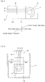
FIG. 6] FIG. 6 is a cross-sectional view of the measurement device used in the cyclic voltammetry of Comparative Example 1. - [
FIG. 7] FIG. 7 illustrates the cyclic voltammogram and diffusion constant of Example 1. - [
FIG. 8] FIG. 8 illustrates the cyclic voltammogram and diffusion constant of Comparative Example 1. - [
FIG. 9] FIG. 9 illustrates the cyclic voltammogram of Example 2. - The electrode device of the present invention includes a first electrode, a second electrode, and an ion-conducting medium extending over the first electrode and the second electrode. The ion-conducting medium consists of a bicontinuous microemulsion including a water phase that is a continuous phase and an oil phase that is a continuous phase. At least one of the water phase and the oil phase is a gel.
- The first embodiment of an electrode device in which the water phase is a gel will be described.
- As illustrated in
FIG. 1C andFIG. 2D , anelectrode device 1 is an example of an electrode for an electrochemical analysis or an electrochemical measurement electrode. Theelectrode device 1 has an approximately plate shape having a one-side surface and the other-side surface that face each other in a thickness direction. Further, theelectrode device 1 has an approximately rectangular shape (longitudinally long rectangular shape) extending long in a long-length direction orthogonal to the thickness direction and extending short in a short-length direction orthogonal to the thickness direction and the long-length direction in a plan view. - The
electrode device 1 includes asubstrate 2, a plurality ofelectrodes wires 9 each corresponding to the plurality ofelectrodes mask layer 6, and an ion-conductingmedium 7. - The
substrate 2 has a one-side surface 8 and the other-side surface that face each other in the thickness direction. Meanwhile, thesubstrate 2 forms an outer shape of theelectrode device 1 in the plan view. Examples of the material of thesubstrate 2 include an insulating materials such as polymers and ceramics (for example, alumina). The dimensions of thesubstrate 2 are appropriately set depending on the purpose and use of theelectrode device 1. Thesubstrate 2 has a thickness of, for example, 3000 µm or less and, for example, 10 µm or more. Further, thesubstrate 2 has a length in the short-length direction of, for example, 5 mm or more and, for example, 100 mm or less, preferably 30 mm or less. Thesubstrate 2 has a length in the long-length direction of, for example, 10 mm or more, preferably, 20 mm or more and, for example, 1000 mm or less, preferably 50 mm or less. - The plurality of
electrodes side surface 8 of thesubstrate 2. Specifically, the plurality ofelectrodes side surface 8 of thesubstrate 2. Further, the plurality ofelectrodes substrate 2 in the long-length direction. The plurality ofelectrodes - Furthermore, the plurality of
electrodes electrodes electrode 3 as an example of a first electrode, acounter electrode 4 as an example of a second electrode, and areference electrode 5. Preferably, the plurality ofelectrodes electrode 3, thecounter electrode 4, and thereference electrode 5, respectively. - The working
electrode 3 has, for example, an approximately circular plate (disk) shape in the plan view. The workingelectrode 3 has a surface area of, for example, 5 mm2 or more, preferably, 10 mm2 or more. - The
counter electrode 4 is disposed relative to the workingelectrode 3 with a space therebetween. Specifically, the workingelectrode 4 has an approximately arc shape and shares the same center with the workingelectrode 3 in the plan view. The central angle of the workingelectrode 4 is, for example, more than 150°, preferably, more than 180° and, for example, less than 360°, preferably less than 270°. The space between thecounter electrode 4 and the working electrode 3 (the closest distance and the same will apply hereinafter) is, for example, 0.1 mm or more and, for example 10 mm or less. - The
reference electrode 5 is disposed relative to the workingelectrode 3 and thecounter electrode 4 with spaces therebetween. Specifically, thereference electrode 5 has an approximately arc shape (or approximately C shape, or approximately U shape) and shares the same center with the workingelectrode 3 in the plan view. Further, thereference electrode 5 has an arc shape that is an extension of the arc shape of thecounter electrode 4 in its circumferential direction. However, thereference electrode 5 is separated from a one-side end in the circumferential direction of thecounter electrode 4 with a space therebetween in the circumferential direction. The central angle of the workingelectrode 4 is, for example, more than 0°, preferably, more than 30° and, for example, less than 180°, preferably less than 75°. - The other-side ends in the long-length direction of the plurality of
electrodes wires 9. The threewires 9 extend in the long-length direction and face each other with spaces therebetween in the short-length direction. The threewires 9 extend from an intermediate part in the long-length direction of thesubstrate 2 to the other-side end in the long-length direction of thesubstrate 2. - Examples of the materials of the plurality of
electrodes wire 9 include metals, and carbon compounds. Preferably, metals are used. Particularly, as the material of the workingelectrode 3 and thecounter electrode 4, more preferably, gold is used. As the material of thereference electrode 5, more preferably, silver is used. - The thickness of the plurality of
electrodes wires 9 are, for example, identical and, specifically, for example, 500 µm or less, preferably 250 µm or less, more preferably 100 µm or less and, for example 10 µm or more. - The
mask layer 6 is disposed on the one-side surface 8 of thesubstrate 2 so as to cover the one-side ends of the threewires 9. Themask layer 6 has, in the plan view, an approximately rectangular shape (film shape) extending entirely in the short-length direction of thesubstrate 2 at the intermediate part of thesubstrate 2 in the long-length direction. Themask layer 6 defines the plurality ofelectrodes mask layer 6 include the above-described insulating materials (such as polymers). - The ion-conducting
medium 7 has a layer (film) shape extending over the workingelectrode 3, thecounter electrode 4 and thereference electrode 5 so as to cover them. Further, the ion-conductingmedium 7 has an approximately rectangular sheet shape including the workingelectrode 3, thecounter electrode 4, and thereference electrode 5 in the plan view. The ion-conducting medium7 is disposed on the one-side end of the one-side surface 8 of thesubstrate 2 in the long-length direction. The ion-conductingmedium 7 is in contact with: a one-side surface in the thickness-direction and a side surface of the workingelectrode 3; a one-side surface in the thickness direction and a side surface of thecounter electrode 4; a one-side surface in the thickness direction and a side surface of thereference electrode 5; and the one-side surface 8 exposed from the workingelectrode 3, thecounter electrode 4, and thereference electrode 5 on thesubstrate 10. - The ion-conducting
medium 7 consists of a bicontinuous microemulsion. The bicontinuous microemulsion includes a water phase that is a continuous phase and, an oil phase that is a continuous phase. In the bicontinuous microemulsion, the water phase contains, for example, water and an electrolyte (for example, an inorganic salt such as sodium nitrate, sodium chloride, sodium hypochlorite, sodium hypophosphite, or sodium phosphite). The oil phase contains, for example, an organic solvent (aromatic hydrocarbon such as toluene, or aliphatic hydrocarbon such as hexane). Further, the bicontinuous microemulsion contains a surfactant (an anionic surfactant such as sodium lauryl sulfate) and an auxiliary surfactant (lower alcohol having 1 or more and 5 or less carbons such as 2-butanol) that are located in the interface of the water phase and the oil phase. The surfactant and the auxiliary surfactant are located in the interface of the water phase and the oil phase. - Examples, types, and contents (including the content of water) of the above-described electrolyte, organic solvent, surfactant, and auxiliary surfactant and the method of preparing the bicontinuous microemulsion are described in detail in, for example,
Japanese Translation of PCT International Application Publication No. H9-509196 Non-patent document 1. - Further, in the first embodiment, the water phase is a gel. The water phase is prepared as a hydrogel.
- As long as having a network structure formed of the water phase, the hydrogel can be either a soft gel (including a swollen gel) or a hard gel (for example, a silica gel including partially dehydrated silica). As the hydrogel, preferably, a soft hydrogel in which water is swollen is used.
- In the hydrogel, a first gelatinizing agent described below forms a three dimensional network structure at the molecular level in the water phase.
- To prepare the water phase as a soft hydrogel, the first gelatinizing agent is contained in the water phase.
- Examples of the first gelatinizing agent include first to third types. For the first type, a gelatinizing agent material is blended in a water phase and then allowed to react, thereby generating the first gelatinizing agent and simultaneously gelatinizing the water phase. For the second type, the gelatinizing agent is blended in a water phase, and the mixture is heated to temporarily dissolve the first gelatinizing agent in the water phase and then cooled, thereby gelatinizing the water phase. For the third type, the first gelatinizing agent is blended in a water phase and mixed (without heating and cooling), thereby gelatinizing the water phase. The above-described first to third types are not clearly distinguished and, for example, are allowed to overlap.
- Examples of the first type include synthetic polymers such as polyacrylamide compounds, polyacrylic acid compounds, polyvinyl alcohol, and polyamino acid compounds.
- Examples of the second type include natural polymers such as agar, gelatin, agarose, carrageenan, and alginate.
- Examples of the third type include the synthetic polymers exemplified as the first type.
- These can be used singly or in combination.
- Preferably, the first type and the third type are used. More preferably, the first type, specifically, the polyacrylamide compound is used.
- The polyacrylamide compound is polymers of a monomer component containing acrylamide monomers as the main component. The monomer component is included in the gelatinizing agent material. Examples of the acrylamide monomers include nonionic monomers such as acrylamide, and methacrylamide, and anionic monomers such as (meth)acrylamide-methylpropanesulfonate (specifically, sodium salts). Preferably, the non-ionic monomer, more preferably, acrylamide is used. The content of the main component (preferably, the acrylamide monomers) in the monomer component is, for example, more than 50 mass%, preferably 70 mass% or more.
- Further, the monomer component can contain, for example, a cross-linkable monomer having two vinyl groups such as methylenebis (meth)acrylamide. The content of the water-soluble cross-linking agent in the monomer component is the rest of the above-described main component.
- When the polyacrylamide compound is used as the first type, for example, the above-described monomer component is blended together with the water-soluble initiator in the water phase and the oil phase is blended in the mixture to prepare a bicontinuous microemulsion, and then the monomer component is polymerized with, for example, light or heat, thereby preparing the first type. The water-soluble initiator constitutes the gelatinizing agent material together with the monomer component.
- Examples of the water-soluble initiator include a thermal initiator, and a photo initiator (specifically, a hydroxyketone compound such as 1-[4-(2-hydroxyethoxy)-phenyl]-2-hydroxymethyl-1-propane-1-on (Irgacure 2959)). Preferably, a photo initiator is used. The parts by mass of the water-soluble initiator relative to 100 parts by mass of the monomer component is, for example, 1 part by mass or more, preferably 5 parts by mass or more and, for example, 25 parts by mass or less, preferably 15 parts by mass or less.
- The ratio of the first gelatinizing agent (or the ratio of the gelatinizing agent material) (the ratio of the monomer component and the water-soluble initiator in total) relative to 100 parts by mass of the water and the electrolyte in total is, for example, 1 part by mass or more, preferably 5 parts by mass or more and, for example, 40 parts by mass or less, preferably 25 parts by mass or less.
- The ion-conducting
medium 7 is a bicontinuous microemulsion where the water phase gelatinized with the first gelatinizing agent and the oil phase having a higher degree of freedom than that of the water phase are each formed as a continuous phase. The electrolyte is contained in the water phase. The surfactant and the auxiliary surfactant are located in the interface of the water phase and the oil phase. - In the bicontinuous microemulsion, the water phase and the oil phase are continuous. Thus, the gel of the water phase can form a three dimensional network structure. The oil phase exists in pore spaces of the three dimensional network structure. The oil phase is included (incorporated) as a liquid in the gelatinized water phase and can move among the pore spaces relatively freely.
- The degree of freedom of the oil phase has a higher than the degree of freedom of the gelatinized water phase. Meanwhile, in the bicontinuous microemulsion, the oil phase exists in the above-described tiny pore spaces, and thus the fall or leakage of the oil phase from the water phase in the ion-conducting
medium 7 is suppressed. - The thickness of the ion-conducting
medium 7 is a distance between the one-side surface 8 of thesubstrate 10 and the one-side surface of the ion-conductingmedium 7 in the thickness direction and is, for example, 10 µm or more, preferably 100 µm or more and, for example, 1500 µm or less. - To produce the
electrode device 1, for example, as illustrated inFIG. 1A andFIG. 2A , theelectrode substrate 10 including thesubstrate 2 and the plurality ofelectrodes side surface 8 is first prepared. Theelectrode substrate 10 includes the threewires 9 continuous to the plurality ofelectrodes side surface 8 of thesubstrate 2. As theelectrode substrate 10, a commercially available product can be used. - Subsequently, as illustrated in
FIG. 1B andFIG. 2B , themask layer 6 is disposed on theelectrode substrate 10. For example, a film made of polymers is adhered to theelectrode substrate 10. - Thereafter, as illustrated in
FIG. 1C , andFIG. 2C to FIG. 2D , the ion-conductingmedium 7 is disposed on theelectrode substrate 10 so that the ion-conductingmedium 7 is in contact with and extends over the workingelectrode 3, thecounter electrode 4, and thereference electrode 5. - For example, first, a bicontinuous microemulsion in which the water phase is yet to be gelatinized is prepared. Specifically, when the first gelatinizing agent is the first type, water, an electrolyte, an organic solvent, a gelatinizing agent material (a monomer component and a water-soluble initiator), a surfactant, and an auxiliary surfactant are blended and mixed. The electrolyte can be prepared with an electrolyte aqueous solution previously dissolved in water, and then be blended.
- In this manner, the bicontinuous microemulsion containing the water phase containing the water, the electrolyte, and the gelatinizing agent material; the oil phase containing the organic solvent; and the surfactant and auxiliary surfactant existing in the interface between the water phase and the oil phase.
- Subsequently, the above-described
bicontinuous microemulsion 13 is disposed on theelectrode substrate 10 so as to be in contact with and extend over the workingelectrode 3, thecounter electrode 4, and thereference electrode 5. Specifically, thebicontinuous microemulsion 13 is, for example, applied (including dropped) on the workingelectrode 3,counter electrode 4, andreference electrode 5 of the electrode substrate 10 (see the right side view ofFIG. 2B ). - At the time, the
mask layer 6 functions as a weir portion that suppresses the flow of thebicontinuous microemulsion 13 that a liquid at room temperature (25°C) toward thewires 9. - Thereafter, the water phase in the
bicontinuous microemulsion 13 is gelatinized. When the initiator contains a photo initiator, thebicontinuous microemulsion 13 is irradiated with ultraviolet light. Specifically, for example, a covering member 11 (phantom line) having translucency is disposed on one side of the bicontinuous microemulsion in the thickness direction. Subsequently, through the coveringmember 11, thebicontinuous microemulsion 13 is irradiated with ultraviolet light. In this manner, in the water phase, the monomer component in the gelatinizing agent material is polymerized in the presence of the water-soluble initiator, thereby preparing the first gelatinizing agent. At the same time as the preparation of the first gelatinizing agent, a first gel forms the three dimensional network structure at the molecular level in the water phase to form a network structure in the water phase. In this manner, the ion-conductingmedium 7 in which the water phase becomes a gel (chemical gel) is prepared. - In the ion-conducting
medium 7, the electrolyte is contained in the water phase and exists as an ion in the water phase. In the ion-conductingmedium 7, the surfactant and the auxiliary surfactant exist in the interface of the water phase and the oil phase. - In this manner, the
electrode device 1 including theelectrode substrate 10, and the ion-conductingmedium 7 in contact with and extending over the workingelectrode 3, thecounter electrode 4, and thereference electrode 5 is produced. - Next, a method of carrying out cyclic voltammetry of a
solution 14 containing a fat-soluble (hydrophobic or lipophilic) analyte with theelectrode device 1 will be described as an example of a potential control measurement. - The
electrode device 1 is prepared in the method described above. Meanwhile, the other-side ends of threeelectrodes 9 in the long-length direction are electrically connected to a potentiostat through lines not illustrated. - Subsequently, as illustrated in
FIG. 3 , thesolution 14 is disposed on the ion-conductingmedium 7. - The
solution 14 includes, for example, a fat-soluble analyte, and, a fat-soluble solvent dissolving the fat-soluble analyte. The fat-soluble analyte is not especially limited and includes, for example, ferrocene, or an antioxidative substance. Examples of the fat-soluble solvent includes the above-described organic solvents (aromatic solvents such as toluene), edible oils (such as olive oil), and oils for cosmetics. - For example, the ion-conducting
medium 7 is impregnated with the solution by applying (or dropping). Specifically, the solution is applied (dropped) to the one-side surface of the ion-conductingmedium 7 in the thickness direction from one side (for example, an upper side) of the ion-conductingmedium 7 in the thickness direction. The amount of application (drop) of the solution is not especially limited as long as the ion-conductingmedium 7 is impregnated and the ionic conduction between the workingelectrode 3 and thecounter electrode 4 is ensured. - In this manner, the analyte is fat-soluble and thus distributed to the oil phase. In other words, the fat-soluble analyte moves not to the water phase that is a gel but to the oil phase.
- Thereafter, by the cyclic voltammetry, the electrode potential of the working
electrode 3 is cyclically changed. - Then, the ions of the analyte are transferred from the interface continuously existing in proximity to the oil phase (the interface of the oil phase and the water phase) through the water phase between the working
electrode 3 and thecounter electrode 4. - In this manner, for example, the peak current is detected. Based on the peak current, a diffusion constant D of the fat-soluble analyte is obtained. Specifically, by assigning each parameter to the following expression (1), the diffusion constant D is obtained.
- [Expression 1]

- Each of the parameters in n the expression is described below.
- ip: the peak current
- n = equivalent/mol of the analyte
- A = the surface area cm2 of the working
electrode 3 - D = the diffusion coefficient (cm2/sec)
- C = the concentration of the analyte (mol/ cm3)
- v = the sweep velocity (V/sec)
- Meanwhile, in the
electrode device 1, the ion-conductingmedium 7 extends from the workingelectrode 3 to thecounter electrode 4. Thus, the ionic conduction between the workingelectrode 3 and thecounter electrode 4 can be carried out. - In addition, in the
electrode device 1, the water phase in the bicontinuous microemulsion is a gel. Then, the gel of the water phase includes the liquid of the oil phase, and thus the flux of the ion-conductingmedium 7 is suppressed. Accordingly, the ion-conductingmedium 7 is fixed to the workingelectrode 3 and thecounter electrode 4. As a result, it is not necessary to contain thesolution 14 as described in Non-patent document 1 (seeFIG. 6 ). Hence, the device can be downsized and theelectrode device 1 can easily be handled. - Further, in the
electrode device 1, while the electron transfer from the workingelectrode 3 allows an oxidation-reduction reaction, the ionic conduction from the workingelectrode 3 to thecounter electrode 4 in the ion-conductingmedium 7 is ensured. Thus, an electrochemical analysis, specifically, cyclic voltammetry can be carried out without having an electrolyte solution outside theelectrode device 1. - Furthermore, in the
electrode device 1, with reference to the potential of thereference electrode 5, an electrochemical measurement such as potentiometry, an electrical conductivity measurement, amperometry-voltammetry, or an alternating-current impedance measurement can be carried out. - Furthermore, in the
electrode device 1, the fat-soluble analyte is dissolved in the oil phase. Thus, without containing the electrolyte in the oil phase, the ionic conduction in the fat-soluble analyte can rapidly be carried out in the interface of the oil phase and the water phase. Thus, the fat-soluble analyte can be analyzed without the electrolyte in the oil phase. - Furthermore, in the
electrode device 1, while the workingelectrode 3, thecounter electrode 4 and thereference electrode 5 each have a flat-belt shape, the ion-conductingmedium 7 has a sheet shape. Thus, theelectrode device 1 can be thinned. - In each of the following variations, the same members and steps as in the first embodiment will be given the same numerical references and the detailed description thereof will be omitted. Further, each of the variations has the same operations and effects as those of the first embodiment unless especially described otherwise. Furthermore, the first embodiment and the variations can appropriately be combined.
- In the method of producing the
electrode device 1 in the first embodiment, first, the bicontinuous microemulsion in which the water phase is yet to become a gel is disposed on the workingelectrode 3, thecounter electrode 4, and thereference electrode 5 and, thereafter, the water phase is gelatinized. - However, although not illustrated, for example, after a film of a bicontinuous microemulsion with a gelatinized water phase is prepared, the film of the bicontinuous microemulsion can be brought into contact with (adhered to) the working
electrode 3, thecounter electrode 4, and thereference electrode 5. At the time, by previously impregnating the film of the bicontinuous microemulsion with a solution containing the analyte and, thereafter, bringing the film impregnated with the solution into contact with the workingelectrode 3, thecounter electrode 4, and thereference electrode 5, the application (drop) of thesolution 14 can be omitted. - Further, as an preferable example of the gelatinizing agent, the first type is used to describe the preparation of the ion-conducting
medium 7. However, as the third type that is another preferable example of the gelatinizing agent, synthetic polymers (a polyamide compound) that are previously (separately) synthesized can be blended (dispersed) in the water phase to gelatinize the water phase. - Furthermore, in
FIG. 3 , the solution containing the analyte is applied (dropped) on the one-side surface of the ion-conductingmedium 7 in the thickness direction. However, the solution containing the analyte can alternatively be applied on the other-side surface of the ion-conductingmedium 7 separately produced in the thickness direction and, thereafter, the other-side surface of the ion-conductingmedium 7 is brought into contact with the workingelectrode 3, thecounter electrode 4, and thereference electrode 5. Alternatively, it is also possible to release the ion-conductingmedium 7 formed on theelectrode substrate 10 from theelectrode substrate 10 so that a gap is formed therebetween and, thereafter, dispose thesolution 14 containing the analyte the gap between the ion-conductingmedium 7 and theelectrode substrate 10 and, thereafter, dispose the ion-conductingmedium 7 on theelectrode substrate 10 again. - Further, although not illustrated, the shape of each of the working
electrode 3, thecounter electrode 4, and thereference electrode 5 is not limited to the above, and can be, for example, a comb shape (a comb-shaped electrode). - Preferably, the working
electrode 3, thecounter electrode 4, and thereference electrode 5 are each formed into a flat-belt shape, and the ion-conductingmedium 7 is formed into a sheet shape. Using the structure, theelectrode device 1 can be thinned. - Furthermore, in the first embodiment, the
electrode device 1 includes thesubstrate 2. However, for example, although not illustrated, theelectrode device 1 does not need including thesubstrate 2. - Furthermore, in the first embodiment, the
electrode device 1 includes themask layer 6. However, for example, although not illustrated, theelectrode device 1 does not need including themask layer 6. - In the structures, the ion-conducting
medium 7 extends over the workingelectrode 3, thecounter electrode 4, and thereference electrode 5 while being in contact therewith. Thus, while the oxidation-reduction reaction is allowed in the workingelectrode 3, the corresponding oxidation-reduction reaction is allowed in thecounter electrode 4. By that means, potentiometry can accurately be carried out with respect to the potential of thereference electrode 5. - Further, in addition to the potential control measurement, a galvanostatic measurement (current control measurement) can be carried out. In the structure, the ion-conducting
medium 7 extends over the workingelectrode 3, thecounter electrode 4, and thereference electrode 5 while being in contact therewith. Thus, the galvanostatic measurement can accurately be carried out. - Furthermore, as illustrated in
FIG. 5 , theelectrode device 1 can include the workingelectrode 3 and thecounter electrode 4 without including thereference electrode 5. In the structure, using the workingelectrode 3 and thecounter electrode 4, the potential difference of the analytes caused therebetween can be measured. Specifically, while the electron transfer from the workingelectrode 3 allows an oxidation-reduction reaction, the ionic conduction from the workingelectrode 3 to thecounter electrode 4 in the ion-conductingmedium 7 is ensured. Thus, cyclic voltammetry can be carried out without the electrolyte solution outside theelectrode device 1. - With the
electrode device 1 including the above-described workingelectrode 3 and thecounter electrode 4 without including thereference electrode 5 as the device structure, potentiometry and a galvanostatic measurement can be carried out. In this method, for example, thereference electrode 5 is prepared as a separate member of the electrode device 1 (thereference electrode 5 included in a separate external device), and theelectrode device 1 including the workingelectrode 3 and thecounter electrode 4 is prepared. Thereafter, in a cyclic voltammetry measurement, as the thick solid line ofFIG. 4 shows, theseparate reference electrode 5 is brought into contact with (pressed to) the ion-conducting medium 7 from the outside (for example, the one side in the thickness direction). - In the following second embodiment, the same members and steps as in the first embodiment and the variations will be given the same numerical references and the detailed description thereof will be omitted. Further, the second embodiment has the same operations and effects as those of the first embodiment and the variations unless especially described otherwise. Furthermore, the first embodiment, the variations, and the second embodiment can appropriately be combined.
- The second embodiment in which electrode device with a oil phase that is a gel will be described.
- The oil phase is prepared as an organogel.
- The organogel can be either a soft gel (including a swollen gel) or a hard gel as long as having a network structure formed of the oil phase. As the organogel, preferably, a soft gel is used.
- In the organogel, a second gelatinizing agent described below forms a three dimensional network structure at the molecular level in the oil phase.
- To prepare the oil phase as a soft organogel, the second gelatinizing agent is blended in the oil phase.
- Examples of the second gelatinizing agent include a fourth type and a fifth type. For the fourth type, the second gelatinizing agent is blended into the oil phase, the mixture is heated to temporarily dissolve the second gelatinizing agent into the oil phase and, thereafter, the mixture is cooled, thereby gelatinizing the oil phase. For the fifth type, the second gelatinizing agent is blended and mixed into the oil phase (without heating and cooling), thereby gelatinizing the oil phase.
- Examples of the fourth type include hydroxycarboxylic acid.
- Examples of the fifth type include oil-soluble polymers and amino acid gelatinizing agent.
- These can be used singly or in combination.
- The above-described second gelatinizing agents (the fourth and fifth types) are described in, for example,
Japanese Unexamined Patent Publication No. 2013-141664 - As the second gelatinizing agent, preferably, the fourth type, specifically, hydroxycarboxylic acid is used. More preferably, hydroxycarboxylic acid having 12 or more and 22 or less carbons is used. Even more preferably, 12-hydroxystearic acid is used.
- The ratio of the second gelatinizing agent to 100 parts by mass of the organic solvent is, for example 1 part by mass or more, preferably 5 parts by mass or more and, for example, 40 parts by mass or less, preferably 25 parts by mass or less.
- In the second embodiment, the ion-conducting
medium 7 is a bicontinuous microemulsion in which the oil phase gelatinized by the second gelatinizing agent and the water phase having a higher degree of freedom than that of the oil phase are each formed as a continuous phase. The electrolyte is included in the water phase. - Although having a high degree of freedom, the water phase can exist in proximity to the gelatinized oil phase in the bicontinuous microemulsion. Thus, the fall or leakage of the water phase from the oil phase in the ion-conducting
medium 7 is suppressed. - In a method of producing an
electrode device 1, as illustrated inFIG. 1A andFIG. 2A , anelectrode substrate 10 is prepared. - Next, as illustrated in
FIG. 1B andFIG. 2B , amask layer 6 is disposed on theelectrode substrate 10. - Thereafter, as illustrated in
FIG. 1C ,FIG. 2C, and FIG. 2D , an ion-conductingmedium 7 is disposed on theelectrode substrate 10 so that ion-conductingmedium 7 is in contact with and extends over a workingelectrode 3, acounter electrode 4 and areference electrode 5. - First, a bicontinuous microemulsion in which the oil phase is yet to become a gel is prepared. Specifically, when the second gelatinizing agent is the fourth type, water, an electrolyte, an organic solvent, a second gelatinizing agent, a surfactant and an auxiliary surfactant are blended and mixed to prepare a mixture. Thereafter, the mixture is heated. The heating temperature is, for example, 30°C or more, preferably 35°C or more and, for example, 80°C or less, preferably 70°C or less. Thereafter, the heated mixture is disposed on the working
electrode 3, thecounter electrode 4, and thereference electrode 5 in theelectrode substrate 10. Specifically, the mixture is applied to theelectrode substrate 10. In this manner, an application film of the bicontinuous microemulsion is prepared. - Thereafter, the application film of the bicontinuous microemulsion is cooled down to room temperature (25°C).
- In this manner, the second gelatinizing agent makes the oil phase a gel (specifically, a physical gel). In this manner, on a one-
side surface 8 of theelectrode substrate 10, the ion-conductingmedium 7 in which the oil phase is a gel is formed. - As the ion-conducting
medium 7, the bicontinuous microemulsion that contains the water phase containing the water and the electrolyte, the oil phase containing the organic solvent and thus being a gel, and the surfactant and auxiliary surfactant existing in the interface between the water phase and the oil phase is prepared. - Next, using the
electrode device 1, cyclic voltammetry of an aqueous solution containing a hydrophilic (water-soluble) analyte will be described. - The aqueous solution includes, for example, the above-described hydrophilic analyte and water dissolving the analyte. As long as being ionic, the hydrophilic analyte is not especially limited and the examples thereof include potassium ferricyanide (potassium hexacyanoferrate) and viologen.
- In the cyclic voltammetry measurement, the analyte is hydrophilic (water-soluble) and thus, distributed to the water phase. In other words, the hydrophilic analyte moves not to the oil phase that is a gel but to the water phase and moves between the working
electrode 3 and thecounter electrode 4. - In this manner, for example, the peak current is detected and, based on the detected peak current, a diffusion constant D of the hydrophilic analyte is obtained.
- In the
electrode device 1, the oil phase is a gel. Thus, the gel of the oil phase includes the liquid of the water phase, and thereby suppressing the flux of the ion-conductingmedium 7. Accordingly, the ion-conductingmedium 7 can be fixed to the workingelectrode 3 and thecounter electrode 4. As a result, it is not necessary to contain thesolution 14 as described in Non-patent document 1 (seeFIG. 6 ). Thus, theelectrode device 1 can be downsized and easily be handled. - In the third embodiment, the same members and steps as in the first embodiment, the variations, and the second embodiment will be given the same numerical references and the detailed description thereof will be omitted. Further, the third embodiment has the same operations and effects as those of the first embodiment, the variations, and the second embodiment unless especially described otherwise. Furthermore, the first embodiment, the variations, the second embodiment, and the third embodiment can appropriately be combined.
- In an ion-conducting
medium 7, both of the water phase and the oil phase can be gels. - To prepare the ion-conducting
medium 7, the water phase is gelatinized in conformity with the producing method in the first embodiment, and the oil phase is gelatinized in conformity with the second embodiment. - In the structure, both of the water phase and the oil phase are gels and thus can be fixed to the working
electrode 3, thecounter electrode 4, and thereference electrode 5 more firmly than in the first embodiment and the second embodiment. - Meanwhile, to accurately analyze a fat-soluble analyte or a hydrophilic analyte, the first embodiment or the second embodiment is more appropriate than the third embodiment.
- In the first embodiment, only the water phase is a gel. Thus, the degree of freedom of the diffusion of a fat-soluble substance in the oil phase is higher than that of the third embodiment in which both of the water phase and the oil phase are gels. Hence, the fat-soluble analyte is dissolved and diffused into the oil phase and thus can electrochemically be detected in the working
electrode 3. Meanwhile, the network of the gel in the water phase does not impede the ionic conduction and thus the fat-soluble analyte has excellent responsiveness to the detection. Thus, the fat-soluble analyte can accurately be analyzed. - In the second embodiment, only the oil phase is a gel. Thus, the degree of freedom of in the water phase is higher than that of the third embodiment in which both of the water phase and the oil phase are gels. Hence, when a hydrophilic analyte is dissolved into the water phase, the ionic conduction in the hydrophilic analyte can rapidly be carried out. Thus, the hydrophilic analyte has excellent responsiveness. As a result, the hydrophilic analyte can accurately be analyzed.
- Accordingly, the first embodiment and the second embodiment can respectively analyze a fat-soluble analyte and a hydrophilic analyte more accurately than the third embodiment. Examples
- The present invention will be more specifically described below with reference to Examples and Comparison Example. The present invention is not limited to any of the Examples and Comparison Example. The specific numeral values used in the description below, such as mixing ratios (contents), physical property values, and parameters can be replaced with corresponding mixing ratios (contents), physical property values, parameters in the above-described "DESCRIPTION OF EMBODIMENTS", including the upper limit value (numeral values defined with "or less", and "less than") or the lower limit value (numeral values defined with "or more", and "more than").
- All the components shown in Table 1 were blended in accordance with the amounts shown in Table 1, thereby preparing a bicontinuous microemulsion.
- Separately, as illustrated in
FIG. 1A andFIG. 2A , anelectrode substrate 10 including asubstrate 2, a workingelectrode 3, acounter electrode 4, and areference electrode 5 was prepared. Subsequently, as illustrated inFIG. 1B andFIG. 2B , amask layer 6 made of a polymer film was adhered to theelectrode substrate 10. The material of thesubstrate 2 was alumina. - The surface area of the working
electrode 3 was 12.56 mm2. The material of the workingelectrode 3 and thecounter electrode 4 was gold and the material of thereference electrode 5 was silver. - Next, the above-described bicontinuous microemulsion was dropped on one side of the
electrode substrate 10 in the thickness direction so that the bicontinuous microemulsion would be in contact with and extend over the workingelectrode 3, thecounter electrode 4, and thereference electrode 5. - Thereafter, the
bicontinuous microemulsion 13 was covered with a coveringmember 11 made of glass. Subsequently, thebicontinuous microemulsion 13 was irradiated with ultraviolet light. By that means, a first gelatinizing agent was prepared and simultaneously the water phase was gelatinized. In this manner, the ion-conductingmedium 7 was prepared. The thickness of the ion-conductingmedium 7 was 1000 µm. - Next, 0.1 cm3 of a toluene solution of ferrocene (a fat-soluble analyte) was dropped on a one-side surface of the ion-conducting
medium 7 in the thickness direction. The ferrocene has a concentration of 5 mM. - After 1 minute passed since the drop, cyclic voltammetry was carried out using a potentiostat connected to the
electrode device 1. -
FIG. 7 depicts the cyclic voltammogram and diffusion constant obtained in Example 1. - Except that the water phase of the bicontinuous microemulsion was not gelatinized and an
electrolysis cell 12 was separately prepared as illustrated inFIG. 6 , the same process as Example 1 was carried out. - Next, 10 cm3 of the
same bicontinuous microemulsion 13 as Example 1 in which both of the oil phase and the water phase were not gels but liquids was inserted into theelectrolysis cell 12. - Separately, as illustrated in
FIG. 1A andFIG. 2A , anelectrode substrate 10 was prepared. Subsequently, as illustrated inFIG. 1B andFIG. 2B , amask layer 6 is disposed on theelectrode substrate 10 thereby defining a workingelectrode 3, acounter electrode 4, and areference electrode 5. - Next, as illustrated in
FIG. 6 , thesubstrate 10, the workingelectrode 3, thecounter electrode 4, and thereference electrode 5 were immersed into thebicontinuous microemulsion 13. Thereafter, cyclic voltammetry was carried out. -
FIG. 8 depicts the cyclic voltammogram and diffusion constant obtained in Comparative Example 1. - The same process as Example 1 was carried out except that the preparation of the ion-conducting
medium 7 was changed as described below, the oil phase was gelatinized, and the method of preparing the gel was changed as described below. - In other words, all the components shown in Table 2 were blended and mixed in accordance with the amounts shown in Table 2, thereby preparing the mixture (a bicontinuous microemulsion). Then, the mixture was heated to 40°C.
- Subsequently, the heated mixture was applied to an
electrode substrate 10 disposed on a hot plate heated to 40°C, thereby preparing an application film made of the mixture. - Thereafter, a covering
member 11 with translucency was disposed on a one-side surface in the thickness direction of the application film. - Thereafter, the application film (the mixture) was cooled down to 25°C, thereby gelatinizing the oil phase (as a physical gel). In this manner, an ion-conducting
medium 7 in which the oil phase was a gel was prepared. - Next, 0.1 cm3 of an aqueous solution of potassium ferricyanide (III) (a hydrophilic analyte) was dropped on a one-side surface in the thickness direction of the ion-conducting
medium 7. The potassium ferricyanide (III) had a concentration of 5 mM. - After 1 minute passed since the drop, cyclic voltammetry was carried out using a potentiostat connected to the
electrode device 1. -
FIG. 9 depicts the cyclic voltammogram and diffusion constant obtained in Example 2. - As
FIG. 7 shows, in Example 1, with the ion-conductingmedium 7 of which water phase was a gel, the cyclic voltammetry of ferrocene that was a fat-soluble analyte was carried out. Further, the cyclic voltammograms of the Example 1 and Comparative Example 1 were almost the same and the diffusion constants thereof were nearly identical as well. As a result, it is determined that the excellent accuracy of the cyclic voltammetry was maintained in Example 1. - As
FIG. 9 shows, in Example 2, with the ion-conductingmedium 7 of which oil phase was a gel, the cyclic voltammetry of potassium ferricyanide (III) that was a hydrophilic analyte was carried out.Table 1 Phase Type Amount Oil phase Organic solvent Toluene 10ml Water phase Electrolyte aqueous solution 1M Sodium nitrate aqueous solution 10ml Gelatinizing agent material (First type) Acrylamide monomer Acrylamide 1.777g Cross-linkable monomer N, N'-methylenebisacrylamide 0.3620g Photo initiator Irgacure 2959 0.2028g Surfactant Sodium lauryl sulfate 9.030g Auxiliary surfactant 2-butanol 6.0ml Table 2 Phase Type Amount Oil phase Organic solvent Toluene 20ml Second gelatinizing agent (Fourth type) 12-hydroxystearic acid 3.00g Water phase Water 20ml Sodium chloride 1.30g Surfactant Sodium lauryl sulfate 2.50g Auxiliary surfactant 2-butanol 5.00ml - While the illustrative embodiments of the present invention are provided in the above description, such is for illustrative purpose only and it is not to be construed as limiting in any manner. Modification and variation of the present invention that will be obvious to those skilled in the art is to be covered by the following claims.
-
- 1
- electrode device
- 3
- working electrode (an example of the first electrode)
- 4
- counter electrode (an example of the second electrode)
- 7
- ion-conducting medium
- 13
- bicontinuous microemulsion
Claims (6)
- An electrode device comprising:a first electrode;a second electrode separated from the second electrode with a space therebetween and; andan ion-conducting medium extending over the first electrode and the second electrode so as to be in contact with the first electrode and the second electrode, whereinthe ion-conducting medium is made of a bicontinuous microemulsion containing a water phase being a continuous phase and an oil phase being a continuous phase, andat least one of the water phase and the oil phase is a gel.
- The electrode device according to Claim 1, whereinthe first electrode is a working electrode, andthe second electrode is a counter electrode.
- The electrode device according to Claim 2, further comprising:a reference electrode separated from the working electrode and the counter electrode with a space between the reference electrode and the working electrode and a space between the reference electrode and the counter electrode, whereinthe ion-conducting medium extending over the working electrode, the counter electrode, and the reference electrode so as to be in contact with the working electrode, the counter electrode, and the reference electrode.
- The electrode device according to Claim 1, wherein one of the water phase and the oil phase is a gel.
- The electrode device according to Claim 4, whereinthe oil phase does not contain an electrolyte, andthe water phase contains an electrolyte.
- The electrode device according to Claim 1, whereinthe first electrode and the second electrode each have a flat-belt shape, andthe ion-conducting medium has a sheet shape.
Applications Claiming Priority (2)
| Application Number | Priority Date | Filing Date | Title |
|---|---|---|---|
| JP2019023535A JP7466135B2 (en) | 2019-02-13 | 2019-02-13 | Electrode device |
| PCT/JP2020/003976 WO2020166416A1 (en) | 2019-02-13 | 2020-02-03 | Electrode device |
Publications (3)
| Publication Number | Publication Date |
|---|---|
| EP3926337A1 true EP3926337A1 (en) | 2021-12-22 |
| EP3926337A4 EP3926337A4 (en) | 2022-11-02 |
| EP3926337B1 EP3926337B1 (en) | 2024-08-21 |
Family
ID=72045505
Family Applications (1)
| Application Number | Title | Priority Date | Filing Date |
|---|---|---|---|
| EP20755920.4A Active EP3926337B1 (en) | 2019-02-13 | 2020-02-03 | Electrode device |
Country Status (5)
| Country | Link |
|---|---|
| US (1) | US20220136992A1 (en) |
| EP (1) | EP3926337B1 (en) |
| JP (1) | JP7466135B2 (en) |
| CN (1) | CN113383231B (en) |
| WO (1) | WO2020166416A1 (en) |
Family Cites Families (7)
| Publication number | Priority date | Publication date | Assignee | Title |
|---|---|---|---|---|
| TW369558B (en) | 1994-01-28 | 1999-09-11 | Minnesota Mining & Mfg | Polymerized microemulsion pressure sensitive adhesive compositions and methods of preparing and using same |
| CN100438206C (en) * | 2003-07-14 | 2008-11-26 | 株式会社藤仓 | Electrolyte composition, photoelectric conversion element using same, and dye-sensitized solar cell |
| WO2010005398A1 (en) * | 2008-07-09 | 2010-01-14 | Agency For Science, Technology And Research | Trapping glucose probe in pores of polymer |
| CN103534588A (en) * | 2011-07-05 | 2014-01-22 | 松下电器产业株式会社 | Method for quantitative determination of chemical substance by substitutional stripping method |
| JP5874063B2 (en) | 2012-01-12 | 2016-03-01 | サンノプコ株式会社 | Antifoam |
| JP6584821B2 (en) * | 2015-04-30 | 2019-10-02 | 株式会社東芝 | Measurement cell, detection device and analysis device |
| WO2017089380A1 (en) * | 2015-11-27 | 2017-06-01 | Radiometer Medical Aps | An outer layer for enzyme sensors |
-
2019
- 2019-02-13 JP JP2019023535A patent/JP7466135B2/en active Active
-
2020
- 2020-02-03 WO PCT/JP2020/003976 patent/WO2020166416A1/en not_active Ceased
- 2020-02-03 EP EP20755920.4A patent/EP3926337B1/en active Active
- 2020-02-03 US US17/429,247 patent/US20220136992A1/en not_active Abandoned
- 2020-02-03 CN CN202080012361.1A patent/CN113383231B/en active Active
Also Published As
| Publication number | Publication date |
|---|---|
| WO2020166416A1 (en) | 2020-08-20 |
| US20220136992A1 (en) | 2022-05-05 |
| EP3926337A4 (en) | 2022-11-02 |
| CN113383231A (en) | 2021-09-10 |
| JP2020134164A (en) | 2020-08-31 |
| EP3926337B1 (en) | 2024-08-21 |
| JP7466135B2 (en) | 2024-04-12 |
| CN113383231B (en) | 2024-05-03 |
Similar Documents
| Publication | Publication Date | Title |
|---|---|---|
| Laws et al. | Bipolar electrode focusing: simultaneous concentration enrichment and separation in a microfluidic channel containing a bipolar electrode | |
| Scholz et al. | A new access to Gibbs energies of transfer of ions across liquid| liquid interfaces and a new method to study electrochemical processes at well-defined three-phase junctions | |
| Schwer et al. | Electrophoresis in fused-silica capillaries: the influence of organic solvents on the electroosmotic velocity and the. zeta. potential | |
| Ciolkowski et al. | Disproportionation during electrooxidation of catecholamines at carbon-fiber microelectrodes | |
| Ulmeanu et al. | Voltammetry at a liquid–liquid interface supported on a metallic electrode | |
| Gulaboski et al. | A comparison of the solvation properties of 2-nitrophenyloctyl ether, nitrobenzene, and n-octanol as assessed by ion transfer experiments | |
| Jin et al. | Multiplexed western blotting using microchip electrophoresis | |
| US8231773B2 (en) | Method of treating nanoparticles using an intermittently processing electrochemical cell | |
| Walsh et al. | Solid‐state sodium‐selective sensors based on screen‐printed Ag/AgCl reference electrodes | |
| Dumitrescu et al. | Pressure-driven bipolar electrochemistry | |
| WO2012114389A1 (en) | Method for quantitative determination of chemical substance by conversion stripping method and sensor chip used for this purpose | |
| EP3926337B1 (en) | Electrode device | |
| Zhang et al. | Electrochemical behavior of labetalol at an ionic liquid modified carbon paste electrode and its electrochemical determination | |
| Gouyon et al. | Characterization of home-made graphite/PDMS microband electrodes for amperometric detection in an original reusable glass-NOA®-PDMS electrophoretic microdevice | |
| Lovrić et al. | Modeling cyclic voltammograms of simultaneous electron and ion transfer reactions at a conic film three-phase electrode | |
| JP2023160684A (en) | micro analysis chip | |
| Hashimoto et al. | Stand-Alone Semi-Solid-State electrochemical systems based on bicontinuous microemulsion gel films | |
| Opallo et al. | Electrochemical redox reaction in a silica sol-gel glass with embedded organic electrolyte | |
| Hyk et al. | Studies of transport phenomena and electrostatic interactions in polyacrylate gels | |
| Dale et al. | A gold–gold oil microtrench electrode for liquid–liquid anion transfer voltammetry | |
| Wojda et al. | Potentiometric studies of bilayers of conducting polymers | |
| CN103534588A (en) | Method for quantitative determination of chemical substance by substitutional stripping method | |
| US20120216604A1 (en) | Method for quantifying a chemical substance by substitutional stripping voltammetry and a sensor chip used therefor | |
| WO2012039076A1 (en) | A method for quantifying a chemical substance with substitutional stripping voltammetry and a sensor chip used therefor | |
| WO2012042697A1 (en) | A method for quantifying a chemical substance with substitutional stripping volammetry and a sensor chip used therefor |
Legal Events
| Date | Code | Title | Description |
|---|---|---|---|
| STAA | Information on the status of an ep patent application or granted ep patent |
Free format text: STATUS: THE INTERNATIONAL PUBLICATION HAS BEEN MADE |
|
| PUAI | Public reference made under article 153(3) epc to a published international application that has entered the european phase |
Free format text: ORIGINAL CODE: 0009012 |
|
| STAA | Information on the status of an ep patent application or granted ep patent |
Free format text: STATUS: REQUEST FOR EXAMINATION WAS MADE |
|
| 17P | Request for examination filed |
Effective date: 20210805 |
|
| AK | Designated contracting states |
Kind code of ref document: A1 Designated state(s): AL AT BE BG CH CY CZ DE DK EE ES FI FR GB GR HR HU IE IS IT LI LT LU LV MC MK MT NL NO PL PT RO RS SE SI SK SM TR |
|
| DAV | Request for validation of the european patent (deleted) | ||
| DAX | Request for extension of the european patent (deleted) | ||
| A4 | Supplementary search report drawn up and despatched |
Effective date: 20220929 |
|
| RIC1 | Information provided on ipc code assigned before grant |
Ipc: G01N 27/48 20060101ALI20220923BHEP Ipc: G01N 27/30 20060101AFI20220923BHEP |
|
| GRAP | Despatch of communication of intention to grant a patent |
Free format text: ORIGINAL CODE: EPIDOSNIGR1 |
|
| STAA | Information on the status of an ep patent application or granted ep patent |
Free format text: STATUS: GRANT OF PATENT IS INTENDED |
|
| INTG | Intention to grant announced |
Effective date: 20230621 |
|
| GRAJ | Information related to disapproval of communication of intention to grant by the applicant or resumption of examination proceedings by the epo deleted |
Free format text: ORIGINAL CODE: EPIDOSDIGR1 |
|
| STAA | Information on the status of an ep patent application or granted ep patent |
Free format text: STATUS: REQUEST FOR EXAMINATION WAS MADE |
|
| GRAP | Despatch of communication of intention to grant a patent |
Free format text: ORIGINAL CODE: EPIDOSNIGR1 |
|
| STAA | Information on the status of an ep patent application or granted ep patent |
Free format text: STATUS: GRANT OF PATENT IS INTENDED |
|
| INTC | Intention to grant announced (deleted) | ||
| INTG | Intention to grant announced |
Effective date: 20231024 |
|
| GRAJ | Information related to disapproval of communication of intention to grant by the applicant or resumption of examination proceedings by the epo deleted |
Free format text: ORIGINAL CODE: EPIDOSDIGR1 |
|
| STAA | Information on the status of an ep patent application or granted ep patent |
Free format text: STATUS: REQUEST FOR EXAMINATION WAS MADE |
|
| GRAP | Despatch of communication of intention to grant a patent |
Free format text: ORIGINAL CODE: EPIDOSNIGR1 |
|
| P01 | Opt-out of the competence of the unified patent court (upc) registered |
Effective date: 20240207 |
|
| STAA | Information on the status of an ep patent application or granted ep patent |
Free format text: STATUS: GRANT OF PATENT IS INTENDED |
|
| INTC | Intention to grant announced (deleted) | ||
| INTG | Intention to grant announced |
Effective date: 20240314 |
|
| GRAS | Grant fee paid |
Free format text: ORIGINAL CODE: EPIDOSNIGR3 |
|
| GRAA | (expected) grant |
Free format text: ORIGINAL CODE: 0009210 |
|
| STAA | Information on the status of an ep patent application or granted ep patent |
Free format text: STATUS: THE PATENT HAS BEEN GRANTED |
|
| AK | Designated contracting states |
Kind code of ref document: B1 Designated state(s): AL AT BE BG CH CY CZ DE DK EE ES FI FR GB GR HR HU IE IS IT LI LT LU LV MC MK MT NL NO PL PT RO RS SE SI SK SM TR |
|
| REG | Reference to a national code |
Ref country code: GB Ref legal event code: FG4D |
|
| REG | Reference to a national code |
Ref country code: CH Ref legal event code: EP |
|
| REG | Reference to a national code |
Ref country code: IE Ref legal event code: FG4D |
|
| REG | Reference to a national code |
Ref country code: DE Ref legal event code: R096 Ref document number: 602020036257 Country of ref document: DE |
|
| REG | Reference to a national code |
Ref country code: LT Ref legal event code: MG9D |
|
| REG | Reference to a national code |
Ref country code: NL Ref legal event code: MP Effective date: 20240821 |
|
| PG25 | Lapsed in a contracting state [announced via postgrant information from national office to epo] |
Ref country code: NO Free format text: LAPSE BECAUSE OF FAILURE TO SUBMIT A TRANSLATION OF THE DESCRIPTION OR TO PAY THE FEE WITHIN THE PRESCRIBED TIME-LIMIT Effective date: 20241121 |
|
| REG | Reference to a national code |
Ref country code: AT Ref legal event code: MK05 Ref document number: 1715946 Country of ref document: AT Kind code of ref document: T Effective date: 20240821 |
|
| PG25 | Lapsed in a contracting state [announced via postgrant information from national office to epo] |
Ref country code: NL Free format text: LAPSE BECAUSE OF FAILURE TO SUBMIT A TRANSLATION OF THE DESCRIPTION OR TO PAY THE FEE WITHIN THE PRESCRIBED TIME-LIMIT Effective date: 20240821 Ref country code: FI Free format text: LAPSE BECAUSE OF FAILURE TO SUBMIT A TRANSLATION OF THE DESCRIPTION OR TO PAY THE FEE WITHIN THE PRESCRIBED TIME-LIMIT Effective date: 20240821 Ref country code: PT Free format text: LAPSE BECAUSE OF FAILURE TO SUBMIT A TRANSLATION OF THE DESCRIPTION OR TO PAY THE FEE WITHIN THE PRESCRIBED TIME-LIMIT Effective date: 20241223 Ref country code: GR Free format text: LAPSE BECAUSE OF FAILURE TO SUBMIT A TRANSLATION OF THE DESCRIPTION OR TO PAY THE FEE WITHIN THE PRESCRIBED TIME-LIMIT Effective date: 20241122 Ref country code: PL Free format text: LAPSE BECAUSE OF FAILURE TO SUBMIT A TRANSLATION OF THE DESCRIPTION OR TO PAY THE FEE WITHIN THE PRESCRIBED TIME-LIMIT Effective date: 20240821 |
|
| PG25 | Lapsed in a contracting state [announced via postgrant information from national office to epo] |
Ref country code: BG Free format text: LAPSE BECAUSE OF FAILURE TO SUBMIT A TRANSLATION OF THE DESCRIPTION OR TO PAY THE FEE WITHIN THE PRESCRIBED TIME-LIMIT Effective date: 20240821 |
|
| PG25 | Lapsed in a contracting state [announced via postgrant information from national office to epo] |
Ref country code: LV Free format text: LAPSE BECAUSE OF FAILURE TO SUBMIT A TRANSLATION OF THE DESCRIPTION OR TO PAY THE FEE WITHIN THE PRESCRIBED TIME-LIMIT Effective date: 20240821 |
|
| PG25 | Lapsed in a contracting state [announced via postgrant information from national office to epo] |
Ref country code: AT Free format text: LAPSE BECAUSE OF FAILURE TO SUBMIT A TRANSLATION OF THE DESCRIPTION OR TO PAY THE FEE WITHIN THE PRESCRIBED TIME-LIMIT Effective date: 20240821 Ref country code: IS Free format text: LAPSE BECAUSE OF FAILURE TO SUBMIT A TRANSLATION OF THE DESCRIPTION OR TO PAY THE FEE WITHIN THE PRESCRIBED TIME-LIMIT Effective date: 20241221 |
|
| PG25 | Lapsed in a contracting state [announced via postgrant information from national office to epo] |
Ref country code: HR Free format text: LAPSE BECAUSE OF FAILURE TO SUBMIT A TRANSLATION OF THE DESCRIPTION OR TO PAY THE FEE WITHIN THE PRESCRIBED TIME-LIMIT Effective date: 20240821 |
|
| PG25 | Lapsed in a contracting state [announced via postgrant information from national office to epo] |
Ref country code: ES Free format text: LAPSE BECAUSE OF FAILURE TO SUBMIT A TRANSLATION OF THE DESCRIPTION OR TO PAY THE FEE WITHIN THE PRESCRIBED TIME-LIMIT Effective date: 20240821 Ref country code: RS Free format text: LAPSE BECAUSE OF FAILURE TO SUBMIT A TRANSLATION OF THE DESCRIPTION OR TO PAY THE FEE WITHIN THE PRESCRIBED TIME-LIMIT Effective date: 20241121 |
|
| PG25 | Lapsed in a contracting state [announced via postgrant information from national office to epo] |
Ref country code: RS Free format text: LAPSE BECAUSE OF FAILURE TO SUBMIT A TRANSLATION OF THE DESCRIPTION OR TO PAY THE FEE WITHIN THE PRESCRIBED TIME-LIMIT Effective date: 20241121 Ref country code: PT Free format text: LAPSE BECAUSE OF FAILURE TO SUBMIT A TRANSLATION OF THE DESCRIPTION OR TO PAY THE FEE WITHIN THE PRESCRIBED TIME-LIMIT Effective date: 20241223 Ref country code: PL Free format text: LAPSE BECAUSE OF FAILURE TO SUBMIT A TRANSLATION OF THE DESCRIPTION OR TO PAY THE FEE WITHIN THE PRESCRIBED TIME-LIMIT Effective date: 20240821 Ref country code: NO Free format text: LAPSE BECAUSE OF FAILURE TO SUBMIT A TRANSLATION OF THE DESCRIPTION OR TO PAY THE FEE WITHIN THE PRESCRIBED TIME-LIMIT Effective date: 20241121 Ref country code: NL Free format text: LAPSE BECAUSE OF FAILURE TO SUBMIT A TRANSLATION OF THE DESCRIPTION OR TO PAY THE FEE WITHIN THE PRESCRIBED TIME-LIMIT Effective date: 20240821 Ref country code: LV Free format text: LAPSE BECAUSE OF FAILURE TO SUBMIT A TRANSLATION OF THE DESCRIPTION OR TO PAY THE FEE WITHIN THE PRESCRIBED TIME-LIMIT Effective date: 20240821 Ref country code: IS Free format text: LAPSE BECAUSE OF FAILURE TO SUBMIT A TRANSLATION OF THE DESCRIPTION OR TO PAY THE FEE WITHIN THE PRESCRIBED TIME-LIMIT Effective date: 20241221 Ref country code: HR Free format text: LAPSE BECAUSE OF FAILURE TO SUBMIT A TRANSLATION OF THE DESCRIPTION OR TO PAY THE FEE WITHIN THE PRESCRIBED TIME-LIMIT Effective date: 20240821 Ref country code: GR Free format text: LAPSE BECAUSE OF FAILURE TO SUBMIT A TRANSLATION OF THE DESCRIPTION OR TO PAY THE FEE WITHIN THE PRESCRIBED TIME-LIMIT Effective date: 20241122 Ref country code: FI Free format text: LAPSE BECAUSE OF FAILURE TO SUBMIT A TRANSLATION OF THE DESCRIPTION OR TO PAY THE FEE WITHIN THE PRESCRIBED TIME-LIMIT Effective date: 20240821 Ref country code: ES Free format text: LAPSE BECAUSE OF FAILURE TO SUBMIT A TRANSLATION OF THE DESCRIPTION OR TO PAY THE FEE WITHIN THE PRESCRIBED TIME-LIMIT Effective date: 20240821 Ref country code: BG Free format text: LAPSE BECAUSE OF FAILURE TO SUBMIT A TRANSLATION OF THE DESCRIPTION OR TO PAY THE FEE WITHIN THE PRESCRIBED TIME-LIMIT Effective date: 20240821 Ref country code: AT Free format text: LAPSE BECAUSE OF FAILURE TO SUBMIT A TRANSLATION OF THE DESCRIPTION OR TO PAY THE FEE WITHIN THE PRESCRIBED TIME-LIMIT Effective date: 20240821 |
|
| PG25 | Lapsed in a contracting state [announced via postgrant information from national office to epo] |
Ref country code: DK Free format text: LAPSE BECAUSE OF FAILURE TO SUBMIT A TRANSLATION OF THE DESCRIPTION OR TO PAY THE FEE WITHIN THE PRESCRIBED TIME-LIMIT Effective date: 20240821 Ref country code: RO Free format text: LAPSE BECAUSE OF FAILURE TO SUBMIT A TRANSLATION OF THE DESCRIPTION OR TO PAY THE FEE WITHIN THE PRESCRIBED TIME-LIMIT Effective date: 20240821 Ref country code: SM Free format text: LAPSE BECAUSE OF FAILURE TO SUBMIT A TRANSLATION OF THE DESCRIPTION OR TO PAY THE FEE WITHIN THE PRESCRIBED TIME-LIMIT Effective date: 20240821 |
|
| PG25 | Lapsed in a contracting state [announced via postgrant information from national office to epo] |
Ref country code: EE Free format text: LAPSE BECAUSE OF FAILURE TO SUBMIT A TRANSLATION OF THE DESCRIPTION OR TO PAY THE FEE WITHIN THE PRESCRIBED TIME-LIMIT Effective date: 20240821 |
|
| PG25 | Lapsed in a contracting state [announced via postgrant information from national office to epo] |
Ref country code: CZ Free format text: LAPSE BECAUSE OF FAILURE TO SUBMIT A TRANSLATION OF THE DESCRIPTION OR TO PAY THE FEE WITHIN THE PRESCRIBED TIME-LIMIT Effective date: 20240821 |
|
| PG25 | Lapsed in a contracting state [announced via postgrant information from national office to epo] |
Ref country code: SK Free format text: LAPSE BECAUSE OF FAILURE TO SUBMIT A TRANSLATION OF THE DESCRIPTION OR TO PAY THE FEE WITHIN THE PRESCRIBED TIME-LIMIT Effective date: 20240821 Ref country code: IT Free format text: LAPSE BECAUSE OF FAILURE TO SUBMIT A TRANSLATION OF THE DESCRIPTION OR TO PAY THE FEE WITHIN THE PRESCRIBED TIME-LIMIT Effective date: 20240821 |
|
| REG | Reference to a national code |
Ref country code: DE Ref legal event code: R097 Ref document number: 602020036257 Country of ref document: DE |
|
| PLBE | No opposition filed within time limit |
Free format text: ORIGINAL CODE: 0009261 |
|
| STAA | Information on the status of an ep patent application or granted ep patent |
Free format text: STATUS: NO OPPOSITION FILED WITHIN TIME LIMIT |
|
| 26N | No opposition filed |
Effective date: 20250522 |
|
| PG25 | Lapsed in a contracting state [announced via postgrant information from national office to epo] |
Ref country code: SE Free format text: LAPSE BECAUSE OF FAILURE TO SUBMIT A TRANSLATION OF THE DESCRIPTION OR TO PAY THE FEE WITHIN THE PRESCRIBED TIME-LIMIT Effective date: 20240821 |
|
| PG25 | Lapsed in a contracting state [announced via postgrant information from national office to epo] |
Ref country code: MC Free format text: LAPSE BECAUSE OF FAILURE TO SUBMIT A TRANSLATION OF THE DESCRIPTION OR TO PAY THE FEE WITHIN THE PRESCRIBED TIME-LIMIT Effective date: 20240821 |
|
| REG | Reference to a national code |
Ref country code: CH Ref legal event code: PL |
|
| PG25 | Lapsed in a contracting state [announced via postgrant information from national office to epo] |
Ref country code: LU Free format text: LAPSE BECAUSE OF NON-PAYMENT OF DUE FEES Effective date: 20250203 |
|
| PG25 | Lapsed in a contracting state [announced via postgrant information from national office to epo] |
Ref country code: CH Free format text: LAPSE BECAUSE OF NON-PAYMENT OF DUE FEES Effective date: 20250228 |
|
| GBPC | Gb: european patent ceased through non-payment of renewal fee |
Effective date: 20250203 |
|
| REG | Reference to a national code |
Ref country code: BE Ref legal event code: MM Effective date: 20250228 |
|
| PG25 | Lapsed in a contracting state [announced via postgrant information from national office to epo] |
Ref country code: GB Free format text: LAPSE BECAUSE OF NON-PAYMENT OF DUE FEES Effective date: 20250203 |
|
| PG25 | Lapsed in a contracting state [announced via postgrant information from national office to epo] |
Ref country code: FR Free format text: LAPSE BECAUSE OF NON-PAYMENT OF DUE FEES Effective date: 20250228 |
|
| PG25 | Lapsed in a contracting state [announced via postgrant information from national office to epo] |
Ref country code: BE Free format text: LAPSE BECAUSE OF NON-PAYMENT OF DUE FEES Effective date: 20250228 |
|
| PG25 | Lapsed in a contracting state [announced via postgrant information from national office to epo] |
Ref country code: IE Free format text: LAPSE BECAUSE OF NON-PAYMENT OF DUE FEES Effective date: 20250203 |
|
| PGFP | Annual fee paid to national office [announced via postgrant information from national office to epo] |
Ref country code: DE Payment date: 20260114 Year of fee payment: 7 |