EP3926241A1 - Cooking tray - Google Patents
Cooking tray Download PDFInfo
- Publication number
- EP3926241A1 EP3926241A1 EP20382522.9A EP20382522A EP3926241A1 EP 3926241 A1 EP3926241 A1 EP 3926241A1 EP 20382522 A EP20382522 A EP 20382522A EP 3926241 A1 EP3926241 A1 EP 3926241A1
- Authority
- EP
- European Patent Office
- Prior art keywords
- cooking tray
- contact
- cooking
- contact material
- tray according
- Prior art date
- Legal status (The legal status is an assumption and is not a legal conclusion. Google has not performed a legal analysis and makes no representation as to the accuracy of the status listed.)
- Pending
Links
Images

Classifications
-
- F—MECHANICAL ENGINEERING; LIGHTING; HEATING; WEAPONS; BLASTING
- F24—HEATING; RANGES; VENTILATING
- F24C—DOMESTIC STOVES OR RANGES ; DETAILS OF DOMESTIC STOVES OR RANGES, OF GENERAL APPLICATION
- F24C15/00—Details
- F24C15/16—Shelves, racks or trays inside ovens; Supports therefor
Definitions
- the present invention relates to a cooking tray, the cooking tray comprising at least one contact section for contacting the cooking tray by a user and/or an object.
- the invention further relates to a cooking appliance comprising such cooking tray.
- the cooking tray When using a cooking tray together with a corresponding cooking appliance, in particular an oven, the cooking tray is necessarily heated by the cooking appliance.
- a user wants to handle the cooking tray, he or she may therefore have to use specific protection equipment, such as gloves, oven mitts or potholders. Alternatively, the user has to wait for a significant period of time until the cooking tray may be touched with bare hands.
- isolating coasters or other objects have to be placed between the table and the cooking tray in order to avoid damage caused by the heat of the cooking tray to the object.
- document WO 2009/007729 A1 describes a baking tray with a grip portion comprising a low thermal conductivity temperature resistant material, in particular a heat resistant silicone rubber.
- the improved concept is based on the finding that a low thermal conductivity or, in other words, a good thermal isolation of the contact material is not sufficient to allow a safe handling or placing of the cooking tray. Rather, it has been realized by the inventors that the actual conduction rate of heat from the cooking tray to the user's hand or the object where the cooking tray is to be placed should be minimized. According to the improved concept, this is achieved by using a contact material with a particularly low thermal effusivity.
- a cooking tray comprises at least one contact section for contacting the cooking tray by a user and/or an object.
- the contact section comprises a contact material with a thermal effusivity, which is equal to or smaller than 10 J K- 1 m -2 s -1/2 .
- the cooking tray may also be denoted as food carrier or carrier for a product to be cooked.
- the contact sections may contacted after a particularly short period of time by placing the cooking tray on a table or another supporting object or by touching the contact section manually without using protection equipment like oven mitts. Furthermore, it has been found that conventionally used materials, such a silicone, the described requirements cannot be achieved.
- the thermal effusivity of the contact material lies between 0.0001 J K -1 m -2 s -112 and 10 J K -1 m -2 s -1/2 , in particular between 0.0001 J K -1 m -2 s -1/2 and 5 J K -1 m -2 s -1/2 .
- a maximum service temperature of the contact material is equal or greater than 150°C.
- the service temperature is equal to or greater than 200°C or the service temperature is equal to or greater than 300°C.
- the service temperature may for example be understood as a temperature at which the contact material may be kept essentially permanently, for example at least 12 hours or at least 24 hours, without a significant degradation.
- the cooking tray is suitable for most household cooking appliances such as ovens, microwaves or grills.
- the at least one contact section comprises a handling section for manual handling of the cooking tray by the user and the handling section comprises the contact material.
- the handling section is, in particular, designed for touching the cooking tray by the user, in particular for taking the cooking tray or manual handling by the user.
- the at least one contact section comprises a placing section for placing the cooking tray on an object, in particular on an object to support the cooking tray, and the placing section comprises the contact material.
- the placing section may for example be understood as a section of the cooking tray, which is in contact to an object, when the cooking tray is placed on the object according to an intended use.
- the contact material forms a part of an outer surface of the cooking tray.
- the contact material is, for example, arranged on an outside of the cooking tray and forms a portion to be directly touched by the user or to be in direct contact with an object the cooking tray is to be placed on.
- the low effusivity contact material is in direct contact to the user's hand or the object the cooking tray is to be placed on. Consequently, the heat transfer rate from the cooking tray to the hand or object is limited in a particularly effective manner.
- the contact material forms only a fraction of the outer surface of the cooking tray and does not cover the whole cooking tray or form the whole surface of the cooking tray. Therefore, the cooking tray may be heated efficiently by a heating source, in particular by direct heating. Furthermore, costs for the low effusivity contact material may be reduced in this way. Furthermore, suitable materials for low friction surface coating or other purposes may form other parts of the surface of the cooking tray.
- the at least one contact section comprises a core portion and the contact material covers the core portion at least in part.
- the at least one contact section may comprises a bulk material, for example a solid bulk material, which has not necessarily a low effusivity. Therefore, handling ergonomics may be improved, even in implementations where the contact material is deformable to some extent.
- a thickness of the contact material covering the core portion may range from below 1 mm, for example in case nanostructured coatings are used as a contact material, up to several millimeters, for example, in case foams, fiber materials or wools are used.
- the contact material comprises a fiber material.
- the fiber material comprises fibers, wherein the maximum thickness of the fibers may for example be 1 mm or smaller.
- the fiber material may for example comprise glass fibers and/or aramid fibers. It has been found that such fiber materials may be produced with an effusivity smaller than 10 J K -1 m -2 s -1/2 .
- the contact material comprises a wool.
- the contact material may comprise a metal wool, for example, an aluminum wool, a steel wool, or a bronze wool.
- the contact material may comprise a glass wool or a rock wool. It has been found that such wools may be produced with an effusivity smaller than 10 J K -1 m -2 s -1/2 .
- the contact material comprises a foam material, in particular a stiff foam material or, in other words, a non-flexible or non-compressible foam material.
- the foam material may comprise a glass foam, an aramid foam, a melamine foam and/or a carbon foam and/or a graphite foam.
- foam materials may be produced with an effusivity smaller than 10 J K -1 m -2 s -1/2 .
- the contact material comprises a textile material, in particular, a fabric.
- the contact material comprises carbon nanotubes, graphene, multi-layer graphene and/or other carbon configurations.
- the contact material comprises a nanostructured or microstructured coating.
- a surface of the coating has structures in the range of several micrometers, tenths of micrometers or hundreds of micrometers or has structures in the order of several nanometers, tenths of nanometers or hundreds of nanometers.
- the effective surface of the coating may be significantly increased also allowing to fabricate low effusivity contact materials which also feature a particularly convenient handling experience.
- the nanostructured or microstructured coating covers the core portion at least in part.
- the contact material comprises a plurality of pillars, each of the pillars having a lateral thickness, which is equal to or smaller than 1 mm.
- the lateral thickness is equal to or smaller than 100 ⁇ m, more preferably equal to or smaller than 100 nm.
- the pillars may, for example, have shapes of approximately cylindrical objects, for example with a circular, elliptical, or rectangular base.
- the lateral thickness may then for example be defined as a diameter of the circular base, a maximum diameter of the elliptical base or a maximum diagonal length of the rectangular base.
- pillars for the contact material has the advantage that these may be fabricated in a particularly purposive and controlled manner. Therefore, a contact material with a very reproducible thermal effusivity and a well-controlled manufacturing process is possible.
- each of the pillars has a longitudinal length, which is equal to or greater than one half of the lateral thickness.
- the longitudinal length refers to a direction perpendicular to the base area of the pillar.
- the contact material comprises a material with a plurality of channels, wherein a wall thickness between adjacent channels is equal to or smaller than 1 mm, preferably equal to or smaller than 100 ⁇ m, more preferably equal to or smaller than 100 nm.
- the cooking tray is tub-shaped or well-shaped, in particular, the cooking tray is designed as an oven tray, a baking tray or a sheet pan.
- the cooking tray is plate-shaped, in particular, the cooking tray is designed as a cooking grate.
- the cooking tray may be characterized by a length, a width and a height, wherein the height is smaller than the length and smaller than the width.
- the height is equal to or smaller than a predefined fraction of the length and equal to or smaller than a predefined fraction of the width.
- the predefined fraction of the length and/or the predefined fraction of the width may be for example one quarter, one fifth or one tenth.
- the width and/or the length may for example be equal to or greater than 30 cm.
- the cooking tray is designed as cookware or bakeware.
- the at least one contact section is arranged at the cooking tray to be directly heated by a cooking appliance.
- the cooking appliance may for example be implemented as an oven, a microwave oven or a steam oven.
- That the at least one contact section is directly heated by the cooking appliance may for example be understood such that the heat is directly created in a material of the contact section, in particular in the contact material, rather than in another component of the cooking tray, which is connected to the at least one contact section in a thermally conductive manner.
- the improved concept is particularly beneficial in case of directly heated contact sections, since in this case the applied heat is typically particularly high.
- the cooking tray comprises a main body portion for carrying a product to be cooked and the contact material is connected to the main body portion.
- connection between contact material and main body portion may be achieved by gluing or by using other fixing means, such as screws, snap-in connectors or other means for forming positive connections.
- the main body portion may comprise the core portion.
- the contact material may be shaped such that it may positively connected to the main body portion without fixing means.
- the contact material may be sleeved on the main body portion.
- a cooking appliance in particular an oven, a microwave or a steam oven, comprising a cooking tray according to the improved concept is provided.
- Fig. 1a and Fig. 1b show an exemplary implementation of a cooking tray 1, which is, in the non-limiting example of 1a, designed as an oven tray or a sheet pan.
- Fig. 1a and Fig. 1b also show a cooking appliance 8, for example an oven, which is designed to be used with the cooking tray 1.
- a user 3 handling the cooking tray 1 is shown.
- the cooking tray 1 comprises one or more contact sections 2a, 2b, 2c.
- the contact sections 2a, 2b, 2c may for example be designed as respective handling sections for manual handling of the cooking tray 1 by the user 3.
- the handling sections 2a, 2b, 2c may be designed as grip portions or other portions for manual handling.
- the contact sections 2a, 2b, 2c each comprise a contact material 6 (see Fig. 2 or Fig. 3 ), which has a low thermal effusivity, which is equal to or smaller than 10 J K -1 m -2 s -1/2 .
- a contact material 6 see Fig. 2 or Fig. 3
- the contact sections 2a, 2b, 2c each comprise a contact material 6 (see Fig. 2 or Fig. 3 ), which has a low thermal effusivity, which is equal to or smaller than 10 J K -1 m -2 s -1/2 .
- the amount of heat conduction from the contact sections 2a, 2b, 2c to the hand of the user may be greatly reduced.
- the user 3 may therefore hold or touch the contact sections 2a, 2b, 2c without additional equipment and without the risk of burning.
- a first and a second contact section 2a, 2b may be arranged on the left and right side edges of the cooking tray 1, respectively, so that the user 3 may touch and grip the cooking tray 1 with both hands at the contact sections 2a, 2b. This is shown schematically in Fig. 1b .
- the cooking tray 1 comprises a third contact section 2c, which may for example be arranged on a front edge of the cooking tray 1 to allow the user to pull the cooking tray 1 out of the appliance 8. In this way, a particularly ergonomic handling of the cooking tray 1 is achieved.
- the shown locations of the contact sections 2a, 2b, 2c in Fig. 1a and 1b as well as in the remaining figures are exemplary positions only.
- the cooking tray 1 may for example comprise a main body portion 9 to put a product to be cooked on the cooking tray 1.
- This main body portion 9 may for example comprise a metal portion, in particular a solid metal portion, and optionally a coating of the metal portion.
- the contact material 6 of the contact sections 2a, 2b, 2c may for example be glued or otherwise connected to the main body portion 9.
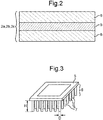
- a part of the main body portion 9 may constitute a core portion 5 as indicated in Fig. 2 with the contact material 6 covering the core portion 5 at least in part.
- the contact material 6 and the main body portion 9 may be forming a butt joint connection.
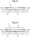
- Fig. 1c shows a further exemplary implementation of the cooking tray 1 in a front view.
- the cooking tray 1 may, for example, correspond to the cooking tray 1 of Fig. 1a and Fig. 1c .
- the contact sections 2a, 2b and the respective contact material 6 may for example surround a bottom edge of the main body portion 9 such that a bottom surface of the cooking tray 1 is at least in part formed by the contact material 6.
- the contact material 6 when the cooking tray 1 is placed on a supporting object 4, for example a table, the contact material 6 is in direct contact with the object 4.
- the contact sections 2a and 2b may then also be considered as placing sections for placing the cooking tray 1 on the object 4.
- the contact sections 2a, 2b may be the only direct contact points or surfaces between the cooking tray 1 and the object 4 or, in other words, the main body portion 9 may not directly contact the object 4.
- the cooking tray 1 may also be placed on the object 4 directly without using isolating base material or coasters or the like without risking a damage of the object 4.
- the contact material 6 may be designed such that it protrudes beyond an edge of the main body portion 9 in the direction facing the object 4 in case of an intended use of the cooking tray 1.
- a gap 10 for example, an air gap, is formed between the main body portion 9 and the object 4 preventing a direct contact between the object 4 and the main body portion 9.
- the cooking tray 1 may, for example, comprise the main body portion 9 and the contact sections 2a, 2b and/or 2c as described with respect to Fig. 1c . Furthermore, the cooking tray 1 may comprise a removable top portion 9' to be placed on top of the main body portion 9 in order to generate a closed cavity for the product to be cooked. Optionally, the top portion 9' may also be equipped with contact sections comprising respective portions of the contact material (not shown in the figures).
- fine metal wools such as steel wools, aluminum wools, or bronze wools
- contact material 6 may be used as contact material 6.
- a fine mesh of wires or, more preferably, a fine wool covering the core portion 5 as shown in Fig. 2 may be used.
- a cover textile may be applied in a similar way.
- foam materials with a particularly low density such as glass foam, aramid foams or melamine foam or low density carbon foam or graphite foam.
- glass fibers, aramid fibers or carbon nanotubes may achieve the required low effusivity.
- these materials can be manufactures with a low surface conductivity and a high heat dissipation and also with an overall low heat capacity and a low density. Still, the materials are suitable in terms of a material strength to avoid a collapse of the contact material 6.
- FIG. 3 Another alternative for the contact material 6 is depicted schematically in Fig. 3 .
- the material 6 of Fig. 3 may also be used in the implementations of Fig. 1a to 1d and Fig. 2 .
- the core portion 5 is equipped with a plurality of pillars 7 connected to the core portion 5 and extending in a longitudinal direction from the core portion 5.
- the pillars 7 constitute the low effusivity contact material 6 in such implementations.
- the lateral thickness D of the pillars 7 may for example be 1 mm or smaller.
- the lateral thickness D lies in the order of 100 ⁇ m or lower or even in the order of 100 nm or lower, such that the pillars 7 may be denoted as micro- or nano-pillars, respectively.
- a longitudinal length H of the pillars 7 may, for example, be one half of the lateral thickness D or greater. It has been shown in the experiments that also such arrangements of nano-pillars are particularly suitable to form a highly mechanical stable and low effusivity material 6.
- nano-channels with respective material dimensions may be used.
- the described materials for the contact material 6 have been proven to allow for a low effusivity as described above. At the same time, those materials are stable under very high temperatures and suffer no or only low corrosion or mechanical degradation, even under during cyclic use.
- the improved concept reduces the amount of transferred heat per time unit from the cooking tray to the user's hands or the object the cooking tray has to be placed on. This is achieved by using a material with a particularly low effusivity. In this way, additional equipment such as pot handles, gloves or oven mitts may be omitted, which allows a particularly convenient and comfortable handling of the cooking tray by the user.
- the low effusivity material may comprise material components, which may feature a low thermal conductivity as a bulk material. But also materials with a relatively high thermal conductivity, such as metals, may be used, provided that the overall effusivity is small enough, as described.
- the cooking tray equipped with a low effusivity material as described allows to touch the cooking tray in a heated state after a short period of time.
- the contact material may also achieve a high amount of heat dissipation at the surface in order to avoid the transmission of heat from the bulk material so that the surface in contact of the material loses most of its heat before or during the contact without being immediately replenished. Also heat transmission may be reduced to a minimum such that a heat which is still transferred to the object or the user's hand is not sufficient to cause any damage or pain.
- the complete contact sections may be made of the low effusivity material or only a surface or coating comprising the low effusivity material may be used on the exterior of the cooking tray covering a core portion.
- the materials described are able to resist a surface temperature of at least 150°C. This qualifies them for applications in cooking appliances as oven, microwave ovens and so forth.
- the described materials are also mechanically robust to resist the pressure over the material due to its own weight so that the structure is not endangered to collapse. Furthermore, it has also been shown that, when touching the material at a surface temperature of 150°C, the surface temperatures of the materials reach less than 60°C after 1 s of contact with the material or less. In other words, by using the materials of low effusivity described, the total time to dissipate the heat once the source of heat has been turned off or removed is increased by orders of magnitude.
- the improved concept a user can contact the surface directly when recently heated just after opening the oven for example.
- the improved concept may also be extended to cover not only cooking trays for products to be cooked but also carriers for products to be applied to cryogenic freezers or other low temperature appliances.
Landscapes
- Engineering & Computer Science (AREA)
- Chemical & Material Sciences (AREA)
- Combustion & Propulsion (AREA)
- Mechanical Engineering (AREA)
- General Engineering & Computer Science (AREA)
- Cookers (AREA)
Abstract
Description
- The present invention relates to a cooking tray, the cooking tray comprising at least one contact section for contacting the cooking tray by a user and/or an object. The invention further relates to a cooking appliance comprising such cooking tray.
- When using a cooking tray together with a corresponding cooking appliance, in particular an oven, the cooking tray is necessarily heated by the cooking appliance. When a user wants to handle the cooking tray, he or she may therefore have to use specific protection equipment, such as gloves, oven mitts or potholders. Alternatively, the user has to wait for a significant period of time until the cooking tray may be touched with bare hands. Furthermore, when placing the cooking tray on a table or another supporting object, isolating coasters or other objects have to be placed between the table and the cooking tray in order to avoid damage caused by the heat of the cooking tray to the object.
- It well-known to equip baking trays or other cooking equipment with material of low thermal conductivity, such as, for example, silicone, in order to reduce the temperature of certain portions of the equipment or the whole equipment piece.
- For example, document
WO 2009/007729 A1 describes a baking tray with a grip portion comprising a low thermal conductivity temperature resistant material, in particular a heat resistant silicone rubber. - Also document
US 2004/0112903 A1 describes cookware with a handle including silicone inserts to improve user handling. In particular, the silicone inserts in the handles increase shall the ease of grabbing and holding the cookware when the cookware is cool and the user is not wearing an oven mitt as well as when the cookware is hot and the user is wearing an oven mitt. - The disadvantage of using known low conductivity materials, such as silicone, is that the item can still only be touched after a significant period of time with bare hands without risking severe injury. For the same reason also the problems sketched above regarding a possible damage of supporting objects is not solved. In consequence, handling the cooking items is uncomfortable and time spending for the user and also may bare the risk of injury or damaging.
- It is therefore an object of the present invention to provide an improved concept for a cooking tray that improves comfort for a user and reduces the risk of injury or damage.
- This object is solved by the subject-matter of the independent claims. Further implementations and preferred embodiments are subject-matter of the dependent claims.
- The improved concept is based on the finding that a low thermal conductivity or, in other words, a good thermal isolation of the contact material is not sufficient to allow a safe handling or placing of the cooking tray. Rather, it has been realized by the inventors that the actual conduction rate of heat from the cooking tray to the user's hand or the object where the cooking tray is to be placed should be minimized. According to the improved concept, this is achieved by using a contact material with a particularly low thermal effusivity.
- According to the improved concept, a cooking tray is provided. The cooking tray comprises at least one contact section for contacting the cooking tray by a user and/or an object. The contact section comprises a contact material with a thermal effusivity, which is equal to or smaller than 10 J K-1 m-2 s-1/2.
- The thermal effusivity e is given by e = (k*p*cp)1/2, wherein k represents the thermal conductivity, ρ represents the density and cp represents the heat capacity of the contact material.
- The cooking tray may also be denoted as food carrier or carrier for a product to be cooked.
- It has been found in experiments that, by using the contact material with a thermal effusivity equal to or smaller than 10 J K-1 m-2 s-1/2, in the following also denoted as "low effusivity", the contact sections may contacted after a particularly short period of time by placing the cooking tray on a table or another supporting object or by touching the contact section manually without using protection equipment like oven mitts. Furthermore, it has been found that conventionally used materials, such a silicone, the described requirements cannot be achieved.
- By using the low effusivity material, however, tests have revealed that the surface of the contact material reaches a temperature less than 60°C after one second of contact when touching the material by the user. Therefore, the risk of injury by manual handling of the cooking tray directly after removing the cooking tray from the cooking appliance or the risk of damaging a table or object the cooking tray is placed on, is significant reduced or even totally suppressed. The user does not have to use protective equipment, such as potholders, oven mitts or protective gloves to handle the cooking tray and also isolating coasters or bases to support the cooking tray when placing it on a surface are not necessary when using a cooking tray according to the improved concept. Consequently, user safety and the level of comfort for the user are improved at the same time.
- According to several implementations, the thermal effusivity of the contact material lies between 0.0001 J K-1 m-2 s-112 and 10 J K-1 m-2 s-1/2, in particular between 0.0001 J K-1 m-2 s-1/2 and 5 J K-1 m-2 s-1/2.
- By using a contact material with a thermal effusivity of 5 J K-1 m-2 s-1/2 or lower, the risk of injury as well as the risk of object damage is further reduced.
- According to several implementations, a maximum service temperature of the contact material is equal or greater than 150°C. Preferably, the service temperature is equal to or greater than 200°C or the service temperature is equal to or greater than 300°C.
- The service temperature may for example be understood as a temperature at which the contact material may be kept essentially permanently, for example at least 12 hours or at least 24 hours, without a significant degradation.
- Therefore, the cooking tray is suitable for most household cooking appliances such as ovens, microwaves or grills.
- According to several implementations, the at least one contact section comprises a handling section for manual handling of the cooking tray by the user and the handling section comprises the contact material.
- The handling section is, in particular, designed for touching the cooking tray by the user, in particular for taking the cooking tray or manual handling by the user.
- According to several implementations, the at least one contact section comprises a placing section for placing the cooking tray on an object, in particular on an object to support the cooking tray, and the placing section comprises the contact material.
- The placing section may for example be understood as a section of the cooking tray, which is in contact to an object, when the cooking tray is placed on the object according to an intended use.
- According to several implementations, the contact material forms a part of an outer surface of the cooking tray.
- In other words, the contact material is, for example, arranged on an outside of the cooking tray and forms a portion to be directly touched by the user or to be in direct contact with an object the cooking tray is to be placed on.
- Therefore, the low effusivity contact material is in direct contact to the user's hand or the object the cooking tray is to be placed on. Consequently, the heat transfer rate from the cooking tray to the hand or object is limited in a particularly effective manner.
- In particular, the contact material forms only a fraction of the outer surface of the cooking tray and does not cover the whole cooking tray or form the whole surface of the cooking tray. Therefore, the cooking tray may be heated efficiently by a heating source, in particular by direct heating. Furthermore, costs for the low effusivity contact material may be reduced in this way. Furthermore, suitable materials for low friction surface coating or other purposes may form other parts of the surface of the cooking tray.
- According to several implementations, the at least one contact section comprises a core portion and the contact material covers the core portion at least in part.
- In other words, the at least one contact section may comprises a bulk material, for example a solid bulk material, which has not necessarily a low effusivity. Therefore, handling ergonomics may be improved, even in implementations where the contact material is deformable to some extent.
- A thickness of the contact material covering the core portion may range from below 1 mm, for example in case nanostructured coatings are used as a contact material, up to several millimeters, for example, in case foams, fiber materials or wools are used.
- According to several implementations, the contact material comprises a fiber material. The fiber material comprises fibers, wherein the maximum thickness of the fibers may for example be 1 mm or smaller.
- The fiber material may for example comprise glass fibers and/or aramid fibers. It has been found that such fiber materials may be produced with an effusivity smaller than 10 J K-1 m-2 s-1/2.
- According to several implementations, the contact material comprises a wool.
- For example, the contact material may comprise a metal wool, for example, an aluminum wool, a steel wool, or a bronze wool. In other implementations, the contact material may comprise a glass wool or a rock wool. It has been found that such wools may be produced with an effusivity smaller than 10 J K-1 m-2 s-1/2.
- According to several implementations, the contact material comprises a foam material, in particular a stiff foam material or, in other words, a non-flexible or non-compressible foam material.
- In particular, the foam material may comprise a glass foam, an aramid foam, a melamine foam and/or a carbon foam and/or a graphite foam.
- It has been found that such foam materials may be produced with an effusivity smaller than 10 J K-1 m-2 s-1/2.
- According to several implementations, the contact material comprises a textile material, in particular, a fabric.
- According to several implementations, the contact material comprises carbon nanotubes, graphene, multi-layer graphene and/or other carbon configurations.
- According to several implementations, the contact material comprises a nanostructured or microstructured coating.
- In other words, a surface of the coating has structures in the range of several micrometers, tenths of micrometers or hundreds of micrometers or has structures in the order of several nanometers, tenths of nanometers or hundreds of nanometers.
- By using nanostructured or microstructured coatings, the effective surface of the coating may be significantly increased also allowing to fabricate low effusivity contact materials which also feature a particularly convenient handling experience.
- According to several implementations, the nanostructured or microstructured coating covers the core portion at least in part.
- According to several implementations, the contact material comprises a plurality of pillars, each of the pillars having a lateral thickness, which is equal to or smaller than 1 mm. Preferably, the lateral thickness is equal to or smaller than 100 µm, more preferably equal to or smaller than 100 nm.
- The pillars may, for example, have shapes of approximately cylindrical objects, for example with a circular, elliptical, or rectangular base. The lateral thickness may then for example be defined as a diameter of the circular base, a maximum diameter of the elliptical base or a maximum diagonal length of the rectangular base.
- Using such pillars for the contact material has the advantage that these may be fabricated in a particularly purposive and controlled manner. Therefore, a contact material with a very reproducible thermal effusivity and a well-controlled manufacturing process is possible.
- According to several implementations, each of the pillars has a longitudinal length, which is equal to or greater than one half of the lateral thickness. The longitudinal length refers to a direction perpendicular to the base area of the pillar.
- According to several implementations, the contact material comprises a material with a plurality of channels, wherein a wall thickness between adjacent channels is equal to or smaller than 1 mm, preferably equal to or smaller than 100 µm, more preferably equal to or smaller than 100 nm.
- According to several implementations, the cooking tray is tub-shaped or well-shaped, in particular, the cooking tray is designed as an oven tray, a baking tray or a sheet pan.
- According to several implementations, the cooking tray is plate-shaped, in particular, the cooking tray is designed as a cooking grate.
- In particular, the cooking tray may be characterized by a length, a width and a height, wherein the height is smaller than the length and smaller than the width.
- For example, the height is equal to or smaller than a predefined fraction of the length and equal to or smaller than a predefined fraction of the width. The predefined fraction of the length and/or the predefined fraction of the width may be for example one quarter, one fifth or one tenth. The width and/or the length may for example be equal to or greater than 30 cm.
- According to several implementations, the cooking tray is designed as cookware or bakeware.
- According to several implementations, the at least one contact section is arranged at the cooking tray to be directly heated by a cooking appliance.
- The cooking appliance ma for example be implemented as an oven, a microwave oven or a steam oven.
- That the at least one contact section is directly heated by the cooking appliance may for example be understood such that the heat is directly created in a material of the contact section, in particular in the contact material, rather than in another component of the cooking tray, which is connected to the at least one contact section in a thermally conductive manner.
- The improved concept is particularly beneficial in case of directly heated contact sections, since in this case the applied heat is typically particularly high.
- According to several implementations, the cooking tray comprises a main body portion for carrying a product to be cooked and the contact material is connected to the main body portion.
- For example, the connection between contact material and main body portion may be achieved by gluing or by using other fixing means, such as screws, snap-in connectors or other means for forming positive connections.
- For example, the main body portion may comprise the core portion.
- Alternatively, the contact material may be shaped such that it may positively connected to the main body portion without fixing means. For example, the contact material may be sleeved on the main body portion.
- According to the improved concept, also a cooking appliance, in particular an oven, a microwave or a steam oven, comprising a cooking tray according to the improved concept is provided.
- Further features of the invention are apparent from the claims, the figures and the description of figures. The features and feature combinations mentioned above in the description as well as the features and feature combinations mentioned below in the description of figures and/or shown in the figures alone may not only be encompassed by the improved concept in the respectively specified combination, but also in other combinations. Thus, implementations of the improved concept are encompassed and disclosed, which may not explicitly be shown in the figures or explained, but arise from and can be generated by separated feature combinations from the explained implementations. Implementations and feature combinations, which do not have all features of an originally formulated claim, may be encompassed by the improved concept. Moreover, implementations and feature combinations, which extend beyond or deviate from the feature combinations set out in the relations of the claims, may be encompassed by the improved concept.
- Further advantages, features and details of the invention are apparent from the claims, the following description of preferred embodiments as well as based on the drawings in which features having analogous functions are designated with the same reference signs.
- In the figures:
- Fig. 1a
- shows an exemplary implementation of a cooking tray according to the improved concept;
- Fig. 1b
- shows a further exemplary implementation of a cooking tray according to the improved concept;
- Fig. 1c
- shows a further exemplary implementation of a cooking tray according to the improved concept;
- Fig. 1d
- shows a further exemplary implementation of a cooking tray according to the improved concept;
- Fig. 2
- shows schematically a part of a contact section of a further exemplary implementation of a cooking tray according to the improved concept; and
- Fig. 3
- shows schematically a contact material of a further exemplary implementation of a cooking tray according to the improved concept.
-
Fig. 1a and Fig. 1b show an exemplary implementation of acooking tray 1, which is, in the non-limiting example of 1a, designed as an oven tray or a sheet pan.Fig. 1a and Fig. 1b also show acooking appliance 8, for example an oven, which is designed to be used with thecooking tray 1. Furthermore, a user 3 handling thecooking tray 1 is shown. - The
cooking tray 1 comprises one ormore contact sections Fig. 1a and Fig. 1b , thecontact sections cooking tray 1 by the user 3. In particular, the handlingsections - The
contact sections Fig. 2 or Fig. 3 ), which has a low thermal effusivity, which is equal to or smaller than 10 J K-1 m-2 s-1/2. In this way, it is ensured that thecooking tray 1 heated by theappliance 8, for example to temperature up to 150°C, 250°C or even higher, may be touched by the user 3 at thecontact sections cooking tray 1 in a particularly convenient way without using equipment such as pot handles or oven mitts. By using thecontact material 6 with low thermal effusivity, in particular, the amount of heat conduction from thecontact sections contact sections - In the example of
Fig. 1a and Fig. 1b , a first and asecond contact section cooking tray 1, respectively, so that the user 3 may touch and grip thecooking tray 1 with both hands at thecontact sections Fig. 1b . - Furthermore, in the examples of
Fig. 1a and Fig. 1b thecooking tray 1 comprises athird contact section 2c, which may for example be arranged on a front edge of thecooking tray 1 to allow the user to pull thecooking tray 1 out of theappliance 8. In this way, a particularly ergonomic handling of thecooking tray 1 is achieved. However, it is pointed out that the shown locations of thecontact sections Fig. 1a and 1b as well as in the remaining figures are exemplary positions only. - The
cooking tray 1 may for example comprise amain body portion 9 to put a product to be cooked on thecooking tray 1. Thismain body portion 9 may for example comprise a metal portion, in particular a solid metal portion, and optionally a coating of the metal portion. - The
contact material 6 of thecontact sections main body portion 9. For example, a part of themain body portion 9 may constitute acore portion 5 as indicated inFig. 2 with thecontact material 6 covering thecore portion 5 at least in part. Alternatively, thecontact material 6 and themain body portion 9 may be forming a butt joint connection. -
Fig. 1c shows a further exemplary implementation of thecooking tray 1 in a front view. Thecooking tray 1 may, for example, correspond to thecooking tray 1 ofFig. 1a andFig. 1c . - As can be seen in
Fig. 1c , thecontact sections respective contact material 6 may for example surround a bottom edge of themain body portion 9 such that a bottom surface of thecooking tray 1 is at least in part formed by thecontact material 6. In other words, when thecooking tray 1 is placed on a supporting object 4, for example a table, thecontact material 6 is in direct contact with the object 4. In particular, thecontact sections cooking tray 1 on the object 4. For example, in case of an intended use of thecooking tray 1, thecontact sections cooking tray 1 and the object 4 or, in other words, themain body portion 9 may not directly contact the object 4. In this way, apart from the advantages related to the improved handling described above, thecooking tray 1 may also be placed on the object 4 directly without using isolating base material or coasters or the like without risking a damage of the object 4. - Among various other possibilities to realize that only the
contact material 6 but not themain body portion 9 is in direct contact with the object 4, thecontact material 6 may be designed such that it protrudes beyond an edge of themain body portion 9 in the direction facing the object 4 in case of an intended use of thecooking tray 1. In this way, agap 10, for example, an air gap, is formed between themain body portion 9 and the object 4 preventing a direct contact between the object 4 and themain body portion 9. - In
Fig. 1d , a further exemplary implementation of thecooking tray 1 according to the improved concept is shown. Thecooking tray 1 may, for example, comprise themain body portion 9 and thecontact sections Fig. 1c . Furthermore, thecooking tray 1 may comprise a removable top portion 9' to be placed on top of themain body portion 9 in order to generate a closed cavity for the product to be cooked. Optionally, the top portion 9' may also be equipped with contact sections comprising respective portions of the contact material (not shown in the figures). - Experiments have shown that a low effusivity of 10 J K-1 m-2 s-1/2 or lower allows to protect the user 3 and the object 4 from high temperature of the directly
heated cooking tray 1. It also has been found that the low thermal conductivity or low heat capacity alone are not sufficient to select a suitable material. In particular, the combination of heat conductivity, heat capacity and material density have to be selected such that the effusivity becomes low enough. The experiments have shown that this may be achieved by fiber materials, wools, foam materials or other materials with little surface contact. - For example, fine metal wools, such as steel wools, aluminum wools, or bronze wools, may be used as
contact material 6. For example, a fine mesh of wires or, more preferably, a fine wool covering thecore portion 5 as shown inFig. 2 may be used. In other implementations, a cover textile may be applied in a similar way. Other alternatives include foam materials with a particularly low density such as glass foam, aramid foams or melamine foam or low density carbon foam or graphite foam. Also glass fibers, aramid fibers or carbon nanotubes may achieve the required low effusivity. - At the same time, these materials can be manufactures with a low surface conductivity and a high heat dissipation and also with an overall low heat capacity and a low density. Still, the materials are suitable in terms of a material strength to avoid a collapse of the
contact material 6. - Another alternative for the
contact material 6 is depicted schematically inFig. 3 . Thematerial 6 ofFig. 3 may also be used in the implementations ofFig. 1a to 1d andFig. 2 . - According to the implementation of
Fig. 3 , thecore portion 5 is equipped with a plurality of pillars 7 connected to thecore portion 5 and extending in a longitudinal direction from thecore portion 5. The pillars 7 constitute the loweffusivity contact material 6 in such implementations. - The lateral thickness D of the pillars 7 may for example be 1 mm or smaller. Preferably, the lateral thickness D lies in the order of 100 µm or lower or even in the order of 100 nm or lower, such that the pillars 7 may be denoted as micro- or nano-pillars, respectively. A longitudinal length H of the pillars 7 may, for example, be one half of the lateral thickness D or greater. It has been shown in the experiments that also such arrangements of nano-pillars are particularly suitable to form a highly mechanical stable and
low effusivity material 6. - In alternative implementations, also nano-channels with respective material dimensions may be used.
- The described materials for the
contact material 6 have been proven to allow for a low effusivity as described above. At the same time, those materials are stable under very high temperatures and suffer no or only low corrosion or mechanical degradation, even under during cyclic use. - As described, the improved concept reduces the amount of transferred heat per time unit from the cooking tray to the user's hands or the object the cooking tray has to be placed on. This is achieved by using a material with a particularly low effusivity. In this way, additional equipment such as pot handles, gloves or oven mitts may be omitted, which allows a particularly convenient and comfortable handling of the cooking tray by the user.
- The low effusivity material may comprise material components, which may feature a low thermal conductivity as a bulk material. But also materials with a relatively high thermal conductivity, such as metals, may be used, provided that the overall effusivity is small enough, as described.
- The cooking tray equipped with a low effusivity material as described allows to touch the cooking tray in a heated state after a short period of time. The contact material may also achieve a high amount of heat dissipation at the surface in order to avoid the transmission of heat from the bulk material so that the surface in contact of the material loses most of its heat before or during the contact without being immediately replenished. Also heat transmission may be reduced to a minimum such that a heat which is still transferred to the object or the user's hand is not sufficient to cause any damage or pain.
- As described, the complete contact sections may be made of the low effusivity material or only a surface or coating comprising the low effusivity material may be used on the exterior of the cooking tray covering a core portion.
- The materials described are able to resist a surface temperature of at least 150°C. This qualifies them for applications in cooking appliances as oven, microwave ovens and so forth.
- The described materials are also mechanically robust to resist the pressure over the material due to its own weight so that the structure is not endangered to collapse. Furthermore, it has also been shown that, when touching the material at a surface temperature of 150°C, the surface temperatures of the materials reach less than 60°C after 1 s of contact with the material or less. In other words, by using the materials of low effusivity described, the total time to dissipate the heat once the source of heat has been turned off or removed is increased by orders of magnitude.
- With the improved concept, a user can contact the surface directly when recently heated just after opening the oven for example. The improved concept may also be extended to cover not only cooking trays for products to be cooked but also carriers for products to be applied to cryogenic freezers or other low temperature appliances.
-
- 1
- cooking tray
- 2a, 2b, 2c
- contact sections
- 3
- user
- 4
- object
- 5
- core portion
- 6
- contact material
- 7
- pillars
- 8
- cooking appliance
- 9
- main body portion
- 9'
- top portion
- 10
- gap
Claims (15)
- Cooking tray comprising at least one contact section (2a, 2b, 2c) for contacting the
cooking tray (1) by a user (3) and/or an object (4), characterized in that the at least one contact section (2a, 2b, 2c) comprises a contact material (6) with a
thermal effusivity, which is equal to or smaller than 10 J K-1 m-2 s-1/2. - Cooking tray according to claim 1, characterized in that- the at least one contact section (2a, 2b, 2c) comprises a handling section (2a, 2b, 2c) for manual handling of the cooking tray (1) by the user (3) and the handling section (2a, 2b, 2c) comprises the contact material (6); and/or- the at least one contact section (2a, 2b, 2c) comprises a placing section (2a, 2b) for placing the cooking tray (1) on the object (4) and the placing section comprises the contact material (6).
- Cooking tray according to one of the preceding claims, characterized in that the contact material (6) forms a part of an outer surface of the cooking tray (1).
- Cooking tray according to one of the preceding claims, characterized in that
the at least one contact section (2a, 2b, 2c) comprises a core portion (5) and the contact material (6) covers the core portion (6) at least in part. - Cooking tray according to one of the preceding claims, characterized in that- the contact material (6) comprises a fiber material, in particular the fiber material comprising glass fibers and/or aramid fibers; and/or- the contact material (6) comprises a wool, in particular a metal wool.
- Cooking tray according to one of the preceding claims, characterized in that
the contact material (6) comprises a foam material, in particular the foam material comprising a glass foam and/or an aramid foam and/or a melamine foam and/or a carbon foam and/or a graphite foam. - Cooking tray according to one of the preceding claims, characterized in that
the contact material (6) comprises a textile material. - Cooking tray according to one of the preceding claims, characterized in that
the contact material (6) comprises carbon nanotubes. - Cooking tray according to one of the preceding claims, characterized in that
the contact material (6) comprises a nanostructured or microstructured coating. - Cooking tray according to one of the preceding claims, characterized in that
the contact material (6) comprises a plurality of pillars (7), each of the pillars (7) having a lateral thickness (D), which is equal to or smaller than 1 mm, in particular equal to or smaller than 100 µm, for example equal to or smaller than 100 nm. - Cooking tray according to claim 10, characterized in that
each of the pillars (7) has a longitudinal length (H), which is equal to or greater than one half of the lateral thickness (D). - Cooking tray according to one of the preceding claims, characterized in that
the cooking tray (1) is designed as cookware, bakeware, an oven tray, a sheet pan or a cooking grate. - Cooking tray according to one of the preceding claims, characterized in that
the at least one contact section (2a, 2b, 2c) is arranged at the cooking tray (1) to be directly heated by a cooking appliance (8). - Cooking tray according to one of the preceding claims, characterized in that
the cooking tray (1) comprises a main body portion (9) for carrying a product to be cooked and the contact material (6) is connected to the main body portion (9). - Cooking appliance comprising a cooking tray (1) according to one of the preceding claims.
Priority Applications (1)
| Application Number | Priority Date | Filing Date | Title |
|---|---|---|---|
| EP20382522.9A EP3926241A1 (en) | 2020-06-17 | 2020-06-17 | Cooking tray |
Applications Claiming Priority (1)
| Application Number | Priority Date | Filing Date | Title |
|---|---|---|---|
| EP20382522.9A EP3926241A1 (en) | 2020-06-17 | 2020-06-17 | Cooking tray |
Publications (1)
| Publication Number | Publication Date |
|---|---|
| EP3926241A1 true EP3926241A1 (en) | 2021-12-22 |
Family
ID=71130928
Family Applications (1)
| Application Number | Title | Priority Date | Filing Date |
|---|---|---|---|
| EP20382522.9A Pending EP3926241A1 (en) | 2020-06-17 | 2020-06-17 | Cooking tray |
Country Status (1)
| Country | Link |
|---|---|
| EP (1) | EP3926241A1 (en) |
Cited By (2)
| Publication number | Priority date | Publication date | Assignee | Title |
|---|---|---|---|---|
| US11561011B2 (en) * | 2020-01-17 | 2023-01-24 | Whirlpool Corporation | Elongated member for a rack |
| WO2025219322A1 (en) | 2024-04-15 | 2025-10-23 | Afi Holding Gmbh | Textile baking sheet for supporting goods to be baked during a baking process, and load-bearing assembly for goods to be baked in a baking oven comprising such a textile baking sheet |
Citations (7)
| Publication number | Priority date | Publication date | Assignee | Title |
|---|---|---|---|---|
| DE19920493A1 (en) * | 1999-05-05 | 2000-11-16 | Schott Glas | Accessory for an oven consists of a material that is sufficiently temperature-resistant at high pyrolysis temperatures produced in an oven |
| US20040112903A1 (en) | 2002-12-13 | 2004-06-17 | Newell Operating Company | Bakeware and handle |
| WO2009007729A1 (en) | 2007-07-12 | 2009-01-15 | Mrx Housewares Limited | Baking tray |
| US20090064989A1 (en) * | 2007-09-06 | 2009-03-12 | Timothy Scott Shaffer | Oven Rack Apparatus and Corresponding Method |
| US7673628B1 (en) * | 2003-05-01 | 2010-03-09 | JAZ Innovations, LLC | Oven rack guard |
| US20170030588A1 (en) * | 2015-07-27 | 2017-02-02 | Planit Products Ltd | Air Permeable Oven Tray and Method of Use |
| US20190003723A1 (en) * | 2017-06-29 | 2019-01-03 | Midea Group Co., Ltd. | Handle for a rack support structure |
-
2020
- 2020-06-17 EP EP20382522.9A patent/EP3926241A1/en active Pending
Patent Citations (7)
| Publication number | Priority date | Publication date | Assignee | Title |
|---|---|---|---|---|
| DE19920493A1 (en) * | 1999-05-05 | 2000-11-16 | Schott Glas | Accessory for an oven consists of a material that is sufficiently temperature-resistant at high pyrolysis temperatures produced in an oven |
| US20040112903A1 (en) | 2002-12-13 | 2004-06-17 | Newell Operating Company | Bakeware and handle |
| US7673628B1 (en) * | 2003-05-01 | 2010-03-09 | JAZ Innovations, LLC | Oven rack guard |
| WO2009007729A1 (en) | 2007-07-12 | 2009-01-15 | Mrx Housewares Limited | Baking tray |
| US20090064989A1 (en) * | 2007-09-06 | 2009-03-12 | Timothy Scott Shaffer | Oven Rack Apparatus and Corresponding Method |
| US20170030588A1 (en) * | 2015-07-27 | 2017-02-02 | Planit Products Ltd | Air Permeable Oven Tray and Method of Use |
| US20190003723A1 (en) * | 2017-06-29 | 2019-01-03 | Midea Group Co., Ltd. | Handle for a rack support structure |
Cited By (2)
| Publication number | Priority date | Publication date | Assignee | Title |
|---|---|---|---|---|
| US11561011B2 (en) * | 2020-01-17 | 2023-01-24 | Whirlpool Corporation | Elongated member for a rack |
| WO2025219322A1 (en) | 2024-04-15 | 2025-10-23 | Afi Holding Gmbh | Textile baking sheet for supporting goods to be baked during a baking process, and load-bearing assembly for goods to be baked in a baking oven comprising such a textile baking sheet |
Similar Documents
| Publication | Publication Date | Title |
|---|---|---|
| US20180206672A1 (en) | High-temperature liner for cooking devices | |
| WO2019014532A1 (en) | Kitchen device | |
| CN101396236A (en) | Cooking device handle with hollow structure | |
| CN1984565A (en) | Baking sheet | |
| CN211510578U (en) | Tobacco baking tool | |
| US20140042172A1 (en) | Serving Mat having a Heated or Freezable Internal Medium | |
| US20120298664A1 (en) | Paired magnetic spoon rest and insulating means | |
| JP4848055B2 (en) | Cooking grip | |
| US10480796B2 (en) | Handle for a rack support structure | |
| JP2011021815A (en) | Heating cooker | |
| CA2622434A1 (en) | Oven rack apparatus and corresponding method | |
| US7673628B1 (en) | Oven rack guard | |
| WO2019213196A1 (en) | Oven cavity shield | |
| JP2017140204A (en) | Cooking utensil | |
| JP2019531162A (en) | Cookware with handle structure | |
| US11627841B2 (en) | Multifunctional tool for holding and manipulating hot items and products | |
| EP2729044B1 (en) | Cooking tool | |
| KR200360915Y1 (en) | Prop for cooking pot | |
| JP3242859U (en) | Insulated retainer | |
| US20140021199A1 (en) | Handle with a heat sink | |
| CN223830895U (en) | Tray assembly and cooking utensil | |
| US12460826B2 (en) | Interlocking dual side hinge door for a domestic kitchen appliance | |
| EP1781070A2 (en) | Accessory for domestic microwave ovens | |
| KR200186437Y1 (en) | A pair of mittens for kitchen | |
| JPH11225887A (en) | Utensil having planted hair having function reducing thermal touch for human skin and equipment |
Legal Events
| Date | Code | Title | Description |
|---|---|---|---|
| PUAI | Public reference made under article 153(3) epc to a published international application that has entered the european phase |
Free format text: ORIGINAL CODE: 0009012 |
|
| STAA | Information on the status of an ep patent application or granted ep patent |
Free format text: STATUS: THE APPLICATION HAS BEEN PUBLISHED |
|
| AK | Designated contracting states |
Kind code of ref document: A1 Designated state(s): AL AT BE BG CH CY CZ DE DK EE ES FI FR GB GR HR HU IE IS IT LI LT LU LV MC MK MT NL NO PL PT RO RS SE SI SK SM TR |
|
| B565 | Issuance of search results under rule 164(2) epc |
Effective date: 20201125 |
|
| STAA | Information on the status of an ep patent application or granted ep patent |
Free format text: STATUS: REQUEST FOR EXAMINATION WAS MADE |
|
| 17P | Request for examination filed |
Effective date: 20220622 |
|
| RBV | Designated contracting states (corrected) |
Designated state(s): AL AT BE BG CH CY CZ DE DK EE ES FI FR GB GR HR HU IE IS IT LI LT LU LV MC MK MT NL NO PL PT RO RS SE SI SK SM TR |
|
| RAP1 | Party data changed (applicant data changed or rights of an application transferred) |
Owner name: BSH HAUSGERAETE GMBH |
|
| STAA | Information on the status of an ep patent application or granted ep patent |
Free format text: STATUS: EXAMINATION IS IN PROGRESS |
|
| 17Q | First examination report despatched |
Effective date: 20240606 |