EP3926234B1 - Direct lighting type panel lamp - Google Patents
Direct lighting type panel lamp Download PDFInfo
- Publication number
- EP3926234B1 EP3926234B1 EP20195285.0A EP20195285A EP3926234B1 EP 3926234 B1 EP3926234 B1 EP 3926234B1 EP 20195285 A EP20195285 A EP 20195285A EP 3926234 B1 EP3926234 B1 EP 3926234B1
- Authority
- EP
- European Patent Office
- Prior art keywords
- base plate
- light source
- source board
- panel lamp
- type panel
- Prior art date
- Legal status (The legal status is an assumption and is not a legal conclusion. Google has not performed a legal analysis and makes no representation as to the accuracy of the status listed.)
- Active
Links
Images



Classifications
-
- F—MECHANICAL ENGINEERING; LIGHTING; HEATING; WEAPONS; BLASTING
- F21—LIGHTING
- F21V—FUNCTIONAL FEATURES OR DETAILS OF LIGHTING DEVICES OR SYSTEMS THEREOF; STRUCTURAL COMBINATIONS OF LIGHTING DEVICES WITH OTHER ARTICLES, NOT OTHERWISE PROVIDED FOR
- F21V19/00—Fastening of light sources or lamp holders
- F21V19/001—Fastening of light sources or lamp holders the light sources being semiconductors devices, e.g. LEDs
- F21V19/003—Fastening of light source holders, e.g. of circuit boards or substrates holding light sources
- F21V19/005—Fastening of light source holders, e.g. of circuit boards or substrates holding light sources by permanent fixing means, e.g. gluing, riveting or embedding in a potting compound
-
- F—MECHANICAL ENGINEERING; LIGHTING; HEATING; WEAPONS; BLASTING
- F21—LIGHTING
- F21V—FUNCTIONAL FEATURES OR DETAILS OF LIGHTING DEVICES OR SYSTEMS THEREOF; STRUCTURAL COMBINATIONS OF LIGHTING DEVICES WITH OTHER ARTICLES, NOT OTHERWISE PROVIDED FOR
- F21V15/00—Protecting lighting devices from damage
- F21V15/01—Housings, e.g. material or assembling of housing parts
-
- F—MECHANICAL ENGINEERING; LIGHTING; HEATING; WEAPONS; BLASTING
- F16—ENGINEERING ELEMENTS AND UNITS; GENERAL MEASURES FOR PRODUCING AND MAINTAINING EFFECTIVE FUNCTIONING OF MACHINES OR INSTALLATIONS; THERMAL INSULATION IN GENERAL
- F16B—DEVICES FOR FASTENING OR SECURING CONSTRUCTIONAL ELEMENTS OR MACHINE PARTS TOGETHER, e.g. NAILS, BOLTS, CIRCLIPS, CLAMPS, CLIPS OR WEDGES; JOINTS OR JOINTING
- F16B5/00—Joining sheets or plates, e.g. panels, to one another or to strips or bars parallel to them
- F16B5/04—Joining sheets or plates, e.g. panels, to one another or to strips or bars parallel to them by means of riveting
-
- F—MECHANICAL ENGINEERING; LIGHTING; HEATING; WEAPONS; BLASTING
- F21—LIGHTING
- F21V—FUNCTIONAL FEATURES OR DETAILS OF LIGHTING DEVICES OR SYSTEMS THEREOF; STRUCTURAL COMBINATIONS OF LIGHTING DEVICES WITH OTHER ARTICLES, NOT OTHERWISE PROVIDED FOR
- F21V29/00—Protecting lighting devices from thermal damage; Cooling or heating arrangements specially adapted for lighting devices or systems
- F21V29/50—Cooling arrangements
- F21V29/502—Cooling arrangements characterised by the adaptation for cooling of specific components
- F21V29/507—Cooling arrangements characterised by the adaptation for cooling of specific components of means for protecting lighting devices from damage, e.g. housings
-
- F—MECHANICAL ENGINEERING; LIGHTING; HEATING; WEAPONS; BLASTING
- F21—LIGHTING
- F21V—FUNCTIONAL FEATURES OR DETAILS OF LIGHTING DEVICES OR SYSTEMS THEREOF; STRUCTURAL COMBINATIONS OF LIGHTING DEVICES WITH OTHER ARTICLES, NOT OTHERWISE PROVIDED FOR
- F21V3/00—Globes; Bowls; Cover glasses
-
- F—MECHANICAL ENGINEERING; LIGHTING; HEATING; WEAPONS; BLASTING
- F21—LIGHTING
- F21Y—INDEXING SCHEME ASSOCIATED WITH SUBCLASSES F21K, F21L, F21S and F21V, RELATING TO THE FORM OR THE KIND OF THE LIGHT SOURCES OR OF THE COLOUR OF THE LIGHT EMITTED
- F21Y2105/00—Planar light sources
- F21Y2105/10—Planar light sources comprising a two-dimensional [2D] array of point-like light-generating elements
- F21Y2105/14—Planar light sources comprising a two-dimensional [2D] array of point-like light-generating elements characterised by the overall shape of the two-dimensional [2D] array
- F21Y2105/16—Planar light sources comprising a two-dimensional [2D] array of point-like light-generating elements characterised by the overall shape of the two-dimensional [2D] array square or rectangular, e.g. for light panels
-
- F—MECHANICAL ENGINEERING; LIGHTING; HEATING; WEAPONS; BLASTING
- F21—LIGHTING
- F21Y—INDEXING SCHEME ASSOCIATED WITH SUBCLASSES F21K, F21L, F21S and F21V, RELATING TO THE FORM OR THE KIND OF THE LIGHT SOURCES OR OF THE COLOUR OF THE LIGHT EMITTED
- F21Y2115/00—Light-generating elements of semiconductor light sources
- F21Y2115/10—Light-emitting diodes [LED]
Definitions
- the present disclosure relates to the field of lighting devices, and in particular to a direct lighting type panel lamp.
- a panel lamp has a thin base plate, thus it is difficult to ensure stable locking of a light source board with screws by means of drilling threaded holes and locking the light source board with the screws. During use, the screws are likely to loosen, whereby the light source board is loosened. For some panel lamps with ultra-thin base plates, threaded holes cannot be made in the base plates.
- Document WO 2014/048395 A1 discloses a lamp according to the preamble of claim 1.
- An object of the present disclosure is to provide a direct lighting type panel lamp, which is intended to solve the problem of large difficulty in fixing light source boards in panel lamps with thin base plates in the prior art.
- a direct lighting type panel lamp comprises a base plate, at least one light source board arranged on the base plate, a rivet connected between the light source board and the base plate, and a diffusion plate connected to the base plate, wherein the base plate is provided with a first riveting through hole, the light source board is provided with a second riveting through hole, and the rivet passes through the first riveting through hole and the second riveting through hole so that the light source board is in riveting connection to the base plate.
- a flexible washer is arranged between the rivet and the base plate, and the flexible washer is arranged surrounding an orifice of the first riveting through hole; and one side of the flexible washer abuts against the base plate, and the other side of the flexible washer abuts against the rivet.
- the flexible washer is a rubber ring or a silicone ring.
- a thermally conductive tape is arranged between the light source board and the base plate, one side of the thermally conductive tape adheres to the light source board, and the other side of the thermally conductive tape abuts against the base plate.
- the base plate is provided with a mounting groove, and the light source board is embedded in the mounting groove.
- an inner side wall of the mounting groove is provided with a retreated notch.
- a connecting component is arranged between the base plate and the diffusion plate, the connecting component is fixedly connected to the base plate, and the diffusion plate is fixedly connected to the connecting component.
- the base plate is provided with connecting through holes
- the connecting component comprises four pressure plates connected end to end in sequence, and connecting screws arranged between the pressure plates and the base plate;
- the pressure plates are provided with connecting threaded holes corresponding to the connecting through holes, and the connecting screws pass through the connecting through holes and are threadedly connected into the connecting threaded holes.
- each of the pressure plates has a surface opposite to the diffusion plate provided as a holding inclined surface.
- a plurality of rivets are arranged between each of the light source boards and the base plate, and the plurality of rivets are arranged in sequence along a length direction of the light source board, with the adjacent rivets being spaced apart by the same distance.
- a plurality of light source boards are provided, the plurality of light source boards are parallel to each other, and the adjacent light source boards are spaced apart by the same distance.
- Each of the light source boards is provided with a plurality of lamp beads. The plurality of lamp beads are arranged in sequence along the length direction of the light source board, and the adjacent lamp beads are spaced apart by the same interval.
- the embodiments of the present disclosure have the following advantageous effects.
- the light source board is first placed on the base plate, and the second riveting through hole of the light source board is aligned with the first riveting through hole of the base plate, a rivet is passed through the first riveting through hole and the second riveting through hole, and the rivet is deformed into a desired pattern by using a rivet pulling tool, so that the light source board is closely attached to the base plate, such that the light source board is fixedly mounted to the base plate.
- This can ensure long-term stability and less loosening of the light source board, as compared with the manner of screw connection.
- orientation or positional relationships indicated by the terms such as “length”, “width”, “up”, “down”, “front”, “rear”, “left”, “right”, “vertical”, “horizontal”, “top”, “bottom”, “inside”, and “outside” are the orientation or positional relationships shown based on the drawings, and these terms are intended only to facilitate the description of the present disclosure and simplify the description, but not intended to indicate or imply that the referred devices or elements must be in a particular orientation, or constructed or operated in the particular orientation, and therefore should not be construed as limiting the present disclosure.
- first and second are used for descriptive purposes only, and should not be understood as an indication or implication of relative importance, or an implicit indication of the number of the indicated technical features. Therefore, a feature defined with the terms “first” or “second” may explicitly or implicitly include one or more such features.
- a plurality means two or more unless otherwise expressly and specifically defined.
- a direct lighting type panel lamp is proposed in an embodiment of the present disclosure, which comprises a base plate 1, at least one light source board 2 arranged on the base plate 1, rivets 3 connected between the light source board 2 and the base plate 1, and a diffusion plate 4 connected to the base plate 1.
- the base plate 1 is provided with first riveting through holes 11
- the light source board 2 is provided with second riveting through holes 21, and the rivet 3 passes through the first riveting through hole 11 and the second riveting through hole 21 so that the light source board 2 is in riveting connection to the base plate 1.
- the light source board 2 is first placed on the base plate 1, and the second riveting through hole 21 of the light source board 2 is aligned with the first riveting through hole 11 of the base plate 1, a rivet 3 is penetrated the first riveting through hole 11 and the second riveting through hole 21, and the rivet 3 is deformed into a desired pattern by using a rivet pulling tool, so that the light source board 2 is closely attached to the base plate 1, such that the light source board 2 is fixedly mounted to the base plate 1.
- This can ensure long-term stability and less loosening of the light source board 2, as compared with the manner of screw connection.
- lamps with ultra-thin base plates 1 which are restricted by the fact that threaded holes cannot be made therein, there are no rigid requirements for the thickness of the base plate 1 in the connection mode using the rivet 3.
- connection mode using the rivet 3 allows more accurate prediction of the lifetime of the stable connection, will not result in volatilization of substances harmful to the environment due to aging of glue, and will not have the problem of poor fixation of the light source board 2 caused by uneven gluing, compared to the traditional gluing method.
- Lantern-shaped rivets 3 may be selected and used as the rivets 3 to achieve a better appearance.
- a flexible washer 5 is arranged between the rivet 3 and the base plate 1, and the flexible washer 5 is arranged surrounding an orifice of the first riveting through hole.
- One side of the flexible washer 5 abuts against the base plate 1, and the other side of the flexible washer 5 abuts against the rivet 3.
- the flexible washer 5 can avoid a rigid contact between the rivet 3 and the outer surface of the base plate 1, so as to avoid damage of the base plate 1 during the riveting process.
- the flexible washer 5 is arranged surrounding an orifice of the first riveting through hole, so that the first riveting through hole can be closed in cooperation with the rivet 3, so as to achieve dustproof and waterproof effects.
- the flexible washer 5 is a rubber ring or a silicone ring, which is deformable to a certain extent and can be brought into close contact with the base plate 1 and the rivet 3, and which has a certain corrosion resistance and can guarantee the waterproof and dustproof performance for a certain period of time.
- a thermally conductive tape 6 is arranged between the light source board 2 and the base plate 1, one side of the thermally conductive tape 6 adheres to the light source board 2, and the other side of the thermally conductive tape 6 abuts against the base plate 1.
- the thermally conductive tape 6 allows good transfer of heat from the light source board 2 to the base plate 1, to improve the heat dissipation performance of the panel lamp.
- the light source board 2 can be preliminarily fixed to the base plate 1 by the thermally conductive tape 6, so that the light source board 2 is not likely to be displaced in the subsequent operation with the rivet 3.
- the base plate 1 is provided with mounting grooves 12, and the light source board 2 is embedded in the mounting groove 12.
- the light source board 2 can be preliminarily positioned in the mounting groove 12 to avoid the displacement of the light source board 2 during riveting with the rivet 3. Also, light interference between adjacent light source boards 2 can be avoided (when a plurality of light source boards 2 are provided).
- the inner side wall of the mounting groove 12 is provided with a retreated notch(es) 13.
- a retreated notch(es) 13 In this way, when an operator is installing a light source board 2 or removing a light source board 2, the operator's fingers can put the light source board 2 into the mounting groove 12 through the retreated notch 13, so that the fingers will not be blocked.
- a connecting component 7 is arranged between the base plate 1 and the diffusion plate 4, the connecting component 7 is fixedly connected to the base plate 1, and the diffusion plate 4 is fixedly connected to the connecting component 7.
- the connecting component 7 is fixedly connected to the base plate 1.
- the base plate 1 is provided with connecting through holes 15, and the connecting component 7 comprises four pressure plates 71 connected end to end in sequence, and connecting screws 72 arranged between the pressure plates 71 and the base plate 1.
- the pressure plates 71 are provided with connecting threaded holes corresponding to the connecting through holes 15, and the connecting screws 72 pass through the connecting through holes 15 and are threadedly connected into the connecting threaded holes.
- each of the pressure plates 71 has a surface opposite to the diffusion plate 4 provided as a holding inclined surface 711.
- the diffusion plate 4 may be positioned and fixed by abutting the edges of the holding inclined surfaces 711 against the diffusion plate 4.
- a plurality of rivets 3 are arranged between each light source board 2 and the base plate 1, and the plurality of rivets 3 are arranged in sequence along the length direction of the light source board 2, with the adjacent rivets 3 being spaced apart by the same distance. In this way, it is ensured that the light source board 2 is well connected and fixed to the base plate 1 as a whole, and the riveted light source board 2 is not likely to be greatly deformed partially and is in a uniform state as a whole.
- a plurality of light source boards 2 are provided.
- the plurality of light source boards 2 are parallel to each other, and the adjacent light source boards 2 are spaced apart by the same distance to achieve a more uniform lighting effect.
- Each of the light source boards 2 is provided with a plurality of lamp beads 22.
- the plurality of lamp beads 22 are arranged in sequence along the length direction of the light source board 2, and the adjacent lamp beads 22 are spaced apart by the same interval to achieve a more uniform lighting effect.
Landscapes
- Engineering & Computer Science (AREA)
- General Engineering & Computer Science (AREA)
- Non-Portable Lighting Devices Or Systems Thereof (AREA)
- Planar Illumination Modules (AREA)
- Securing Globes, Refractors, Reflectors Or The Like (AREA)
Description
- The present disclosure relates to the field of lighting devices, and in particular to a direct lighting type panel lamp.
- A panel lamp has a thin base plate, thus it is difficult to ensure stable locking of a light source board with screws by means of drilling threaded holes and locking the light source board with the screws. During use, the screws are likely to loosen, whereby the light source board is loosened. For some panel lamps with ultra-thin base plates, threaded holes cannot be made in the base plates. Document
WO 2014/048395 A1 discloses a lamp according to the preamble ofclaim 1. - An object of the present disclosure is to provide a direct lighting type panel lamp, which is intended to solve the problem of large difficulty in fixing light source boards in panel lamps with thin base plates in the prior art.
- To achieve this object, the following technical solution is employed in an embodiment of the present disclosure:
A direct lighting type panel lamp comprises a base plate, at least one light source board arranged on the base plate, a rivet connected between the light source board and the base plate, and a diffusion plate connected to the base plate, wherein the base plate is provided with a first riveting through hole, the light source board is provided with a second riveting through hole, and the rivet passes through the first riveting through hole and the second riveting through hole so that the light source board is in riveting connection to the base plate. - In one embodiment, a flexible washer is arranged between the rivet and the base plate, and the flexible washer is arranged surrounding an orifice of the first riveting through hole; and one side of the flexible washer abuts against the base plate, and the other side of the flexible washer abuts against the rivet.
- In one embodiment, the flexible washer is a rubber ring or a silicone ring.
- In one embodiment, a thermally conductive tape is arranged between the light source board and the base plate, one side of the thermally conductive tape adheres to the light source board, and the other side of the thermally conductive tape abuts against the base plate.
- According to the invention, the base plate is provided with a mounting groove, and the light source board is embedded in the mounting groove.
- According to the invention, an inner side wall of the mounting groove is provided with a retreated notch.
- In one embodiment, a connecting component is arranged between the base plate and the diffusion plate, the connecting component is fixedly connected to the base plate, and the diffusion plate is fixedly connected to the connecting component.
- In one embodiment, the base plate is provided with connecting through holes, and the connecting component comprises four pressure plates connected end to end in sequence, and connecting screws arranged between the pressure plates and the base plate; the pressure plates are provided with connecting threaded holes corresponding to the connecting through holes, and the connecting screws pass through the connecting through holes and are threadedly connected into the connecting threaded holes.
- In one embodiment, each of the pressure plates has a surface opposite to the diffusion plate provided as a holding inclined surface.
- In one embodiment, a plurality of rivets are arranged between each of the light source boards and the base plate, and the plurality of rivets are arranged in sequence along a length direction of the light source board, with the adjacent rivets being spaced apart by the same distance.
- In one embodiment, a plurality of light source boards are provided, the plurality of light source boards are parallel to each other, and the adjacent light source boards are spaced apart by the same distance. Each of the light source boards is provided with a plurality of lamp beads. The plurality of lamp beads are arranged in sequence along the length direction of the light source board, and the adjacent lamp beads are spaced apart by the same interval.
- The embodiments of the present disclosure have the following advantageous effects. During assembling of the direct lighting type panel lamp, the light source board is first placed on the base plate, and the second riveting through hole of the light source board is aligned with the first riveting through hole of the base plate, a rivet is passed through the first riveting through hole and the second riveting through hole, and the rivet is deformed into a desired pattern by using a rivet pulling tool, so that the light source board is closely attached to the base plate, such that the light source board is fixedly mounted to the base plate. This can ensure long-term stability and less loosening of the light source board, as compared with the manner of screw connection.
- In order to more clearly illustrate technical solutions of the embodiments of the present disclosure, drawings required for use in the description of the embodiments or the prior art will be described briefly below. It is obvious that the drawings in the following description are merely illustrative of some embodiments of the present disclosure. It will be understood by those of ordinary skill in the art that other drawings can also be obtained from these drawings without any inventive effort.
-
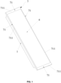
FIG. 1 is a schematic structural view of a direct lighting type panel lamp in an embodiment of the present disclosure; -
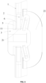
FIG. 2 is a sectional view of a direct lighting type panel lamp in an embodiment of the present disclosure; -
FIG. 3 is a partial enlarged view of a rivet inFIG. 2 ; -
FIG. 4 is a schematic view showing the internal structure of a direct lighting type panel lamp in an embodiment of the present disclosure; and -
FIG. 5 is an exploded view of a direct lighting type panel lamp in an embodiment of the present disclosure; - In the drawings:
1. base plate; 11. first riveting through hole; 12. mounting groove; 13. retreated notch; 15. connecting through hole; 2. light source board; 21. second riveting through hole; 22. lamp bead; 3.rivet 4. diffusion plate; 5. flexible washer; 6. thermally conductive tape; 7. connecting component; 71. pressure plate; 711. holding inclined surface; 72. connecting screw. - In order to further clarify the objects, technical solutions, and advantages of the present disclosure, the present disclosure will be described below in further detail with reference to the drawings and embodiments. It should be understood that the specific embodiments described here are only intended to explain the present disclosure, and not to limit the present disclosure.
- It should be noted that when an element is said to be "fixed to" or "arranged on" another element, it may be directly on the another element or indirectly on the another element. When an element is said to be "connected to" another element, it may be connected directly to the another element or connected indirectly to the another element.
- It should be understood that orientation or positional relationships indicated by the terms such as "length", "width", "up", "down", "front", "rear", "left", "right", "vertical", "horizontal", "top", "bottom", "inside", and "outside" are the orientation or positional relationships shown based on the drawings, and these terms are intended only to facilitate the description of the present disclosure and simplify the description, but not intended to indicate or imply that the referred devices or elements must be in a particular orientation, or constructed or operated in the particular orientation, and therefore should not be construed as limiting the present disclosure.
- In addition, the terms "first" and "second" are used for descriptive purposes only, and should not be understood as an indication or implication of relative importance, or an implicit indication of the number of the indicated technical features. Therefore, a feature defined with the terms "first" or "second" may explicitly or implicitly include one or more such features. In the description of the present disclosure, "a plurality" means two or more unless otherwise expressly and specifically defined.
- The implementation of the present disclosure will be described in detail below in connection with specific embodiments.
- As shown in
FIGS. 1 to 3 , a direct lighting type panel lamp is proposed in an embodiment of the present disclosure, which comprises abase plate 1, at least onelight source board 2 arranged on thebase plate 1, rivets 3 connected between thelight source board 2 and thebase plate 1, and adiffusion plate 4 connected to thebase plate 1. Thebase plate 1 is provided with first riveting throughholes 11, thelight source board 2 is provided with second riveting throughholes 21, and therivet 3 passes through the first riveting throughhole 11 and the second riveting throughhole 21 so that thelight source board 2 is in riveting connection to thebase plate 1. - In the embodiment of the present disclosure, during assembling of the direct lighting type panel lamp, the
light source board 2 is first placed on thebase plate 1, and the second riveting throughhole 21 of thelight source board 2 is aligned with the first riveting throughhole 11 of thebase plate 1, arivet 3 is penetrated the first riveting throughhole 11 and the second riveting throughhole 21, and therivet 3 is deformed into a desired pattern by using a rivet pulling tool, so that thelight source board 2 is closely attached to thebase plate 1, such that thelight source board 2 is fixedly mounted to thebase plate 1. This can ensure long-term stability and less loosening of thelight source board 2, as compared with the manner of screw connection. Especially for lamps withultra-thin base plates 1 which are restricted by the fact that threaded holes cannot be made therein, there are no rigid requirements for the thickness of thebase plate 1 in the connection mode using therivet 3. - The connection mode using the
rivet 3 allows more accurate prediction of the lifetime of the stable connection, will not result in volatilization of substances harmful to the environment due to aging of glue, and will not have the problem of poor fixation of thelight source board 2 caused by uneven gluing, compared to the traditional gluing method. Lantern-shapedrivets 3 may be selected and used as therivets 3 to achieve a better appearance. - Referring to
FIG. 3 , in another specific embodiment of the direct lighting type panel lamp according to the present disclosure, aflexible washer 5 is arranged between therivet 3 and thebase plate 1, and theflexible washer 5 is arranged surrounding an orifice of the first riveting through hole. One side of theflexible washer 5 abuts against thebase plate 1, and the other side of theflexible washer 5 abuts against therivet 3. Theflexible washer 5 can avoid a rigid contact between therivet 3 and the outer surface of thebase plate 1, so as to avoid damage of thebase plate 1 during the riveting process. Moreover, theflexible washer 5 is arranged surrounding an orifice of the first riveting through hole, so that the first riveting through hole can be closed in cooperation with therivet 3, so as to achieve dustproof and waterproof effects. - Referring to
FIG. 3 , in another specific embodiment of the direct lighting type panel lamp according to the present disclosure, theflexible washer 5 is a rubber ring or a silicone ring, which is deformable to a certain extent and can be brought into close contact with thebase plate 1 and therivet 3, and which has a certain corrosion resistance and can guarantee the waterproof and dustproof performance for a certain period of time. - Referring to
FIG. 3 , in another specific embodiment of the direct lighting type lamp panel according to the present disclosure, a thermallyconductive tape 6 is arranged between thelight source board 2 and thebase plate 1, one side of the thermallyconductive tape 6 adheres to thelight source board 2, and the other side of the thermallyconductive tape 6 abuts against thebase plate 1. On the one hand, the thermallyconductive tape 6 allows good transfer of heat from thelight source board 2 to thebase plate 1, to improve the heat dissipation performance of the panel lamp. On the other hand, during the assembling of the panel lamp, thelight source board 2 can be preliminarily fixed to thebase plate 1 by the thermallyconductive tape 6, so that thelight source board 2 is not likely to be displaced in the subsequent operation with therivet 3. - Referring to
FIG. 4 , in another specific embodiment of the direct lighting type panel lamp according to the present disclosure, thebase plate 1 is provided with mountinggrooves 12, and thelight source board 2 is embedded in the mountinggroove 12. Thelight source board 2 can be preliminarily positioned in the mountinggroove 12 to avoid the displacement of thelight source board 2 during riveting with therivet 3. Also, light interference between adjacentlight source boards 2 can be avoided (when a plurality oflight source boards 2 are provided). - Referring to
FIG. 4 , in another specific embodiment of the direct lighting type panel lamp according to the present disclosure, the inner side wall of the mountinggroove 12 is provided with a retreated notch(es) 13. In this way, when an operator is installing alight source board 2 or removing alight source board 2, the operator's fingers can put thelight source board 2 into the mountinggroove 12 through the retreatednotch 13, so that the fingers will not be blocked. - Referring to
FIGS. 4 to 5 , in another specific embodiment of the direct lighting type lamp panel according to the present disclosure, a connectingcomponent 7 is arranged between thebase plate 1 and thediffusion plate 4, the connectingcomponent 7 is fixedly connected to thebase plate 1, and thediffusion plate 4 is fixedly connected to the connectingcomponent 7. During the assembling of the panel lamp, after thelight source board 2 is placed in thebase plate 1, thediffusion plate 4 is fixed to the connectingcomponent 7, and then the connectingcomponent 7 is fixedly connected to thebase plate 1. - Referring to
FIG. 3 , in another specific embodiment of the direct lighting type panel lamp according to the present disclosure, thebase plate 1 is provided with connecting throughholes 15, and the connectingcomponent 7 comprises fourpressure plates 71 connected end to end in sequence, and connectingscrews 72 arranged between thepressure plates 71 and thebase plate 1. Thepressure plates 71 are provided with connecting threaded holes corresponding to the connecting throughholes 15, and the connectingscrews 72 pass through the connecting throughholes 15 and are threadedly connected into the connecting threaded holes. During the assembling of the panel lamp, while thepressure plates 71 are fixed to thebase plate 1, thediffusion plate 4 can be held by thepressure plates 71, and then thediffusion plate 4 is fixed between thepressure plates 71 and thebase plate 1 to achieve the mounting of thediffusion plate 4. - Referring to
FIGS. 1 and5 , in another specific embodiment of the direct lighting type panel lamp according to the present disclosure, each of thepressure plates 71 has a surface opposite to thediffusion plate 4 provided as a holdinginclined surface 711. Thediffusion plate 4 may be positioned and fixed by abutting the edges of the holdinginclined surfaces 711 against thediffusion plate 4. - Referring to
FIG. 4 , in another specific embodiment of the direct lighting type panel lamp according to the present disclosure, a plurality ofrivets 3 are arranged between eachlight source board 2 and thebase plate 1, and the plurality ofrivets 3 are arranged in sequence along the length direction of thelight source board 2, with theadjacent rivets 3 being spaced apart by the same distance. In this way, it is ensured that thelight source board 2 is well connected and fixed to thebase plate 1 as a whole, and the rivetedlight source board 2 is not likely to be greatly deformed partially and is in a uniform state as a whole. - Referring to
FIG. 4 , in another specific embodiment of the direct lighting type panel lamp according to the present disclosure, a plurality oflight source boards 2 are provided. The plurality oflight source boards 2 are parallel to each other, and the adjacentlight source boards 2 are spaced apart by the same distance to achieve a more uniform lighting effect. Each of thelight source boards 2 is provided with a plurality oflamp beads 22. The plurality oflamp beads 22 are arranged in sequence along the length direction of thelight source board 2, and theadjacent lamp beads 22 are spaced apart by the same interval to achieve a more uniform lighting effect. - It can be understood that the solution in another specific embodiment may be an implementable embodiment that is further modified on the basis of other embodiments.
- Apparently, the above embodiments of the present disclosure are given as examples only for clearly illustrating the present disclosure, and are not intended to limit the embodiments of the present disclosure. It will be understood by those of ordinary skill in the art that other variations or changes in different forms may be made on the basis of the above description. It is unnecessary and impossible to enumerate all the embodiments here.
Claims (8)
- A direct lighting type panel lamp, comprising a base plate (1), at least one light source board (2) arranged on the base plate (1), at least one rivet (3) connected between the at least one light source board (2) and the base plate (1), and a diffusion plate (4) connected to the base plate (1), wherein the base plate (1) is provided with at least one first riveting through hole (11), the light source board (2) is provided with at least one second riveting through hole (21), the at least one rivet (3) passes through the at least one first riveting through hole (11) and the at least one second riveting through hole (21), so that the at least one light source board (2) is in riveting connection to the base plate (1), and the base plate (1) is provided with at least one mounting groove (12), and each of the at least one light source board (2) is embedded in one of the at least one mounting groove (12);
characterized in that an inner side wall of each of the at least one mounting groove (12) is provided with at least one retreated notch (13). - The direct lighting type panel lamp according to claim 1, wherein a flexible washer (5) is arranged between each of the at least one rivet (3) and the base plate (1), and the flexible washer (5) is arranged surrounding an orifice of one of the at least one first riveting through hole (11), the flexible washer (5) has one side abutting against the base plate (1), and the other side abutting against one of the at least one rivet (3).
- The direct lighting type panel lamp according to claim 2, wherein the flexible washer (5) is a rubber ring or a silicone ring.
- The direct lighting type panel lamp according to claim 1, wherein a thermally conductive tape (6) is arranged between each of the at least one light source board (2) and the base plate (1), wherein the thermally conductive tape (6) has one side adhering to one of the at least one light source board (2), and the other side abutting against the base plate (1).
- The direct lighting type panel lamp according to any one of claims 1 to 4, wherein a connecting component (7) is arranged between the base plate (1) and the diffusion plate (4), wherein the connecting component (7) is fixedly connected to the base plate (1), and the diffusion plate (4) is fixedly connected to the connecting component (7).
- The direct lighting type panel lamp according to claim 5, wherein the base plate (1) is provided with connecting through holes (15), and the connecting component (7) comprises four pressure plates (71) which are connected end to end in sequence, and connecting screws (72) which are arranged between the pressure plates (71) and the base plate (1), wherein the pressure plates (71) are provided with connecting threaded holes corresponding to the connecting through holes, and the connecting screws (72) pass through the connecting through holes and are threadedly connected into the connecting threaded holes.
- The direct lighting type panel lamp according to claim 6, wherein each of the pressure plates (71) has a surface opposite to the diffusion plate (4) provided as a holding inclined surface (711).
- The direct lighting type panel lamp according to any one of claims 1 to 4, wherein a plurality of rivets (3) are arranged between each of the at least one light source board (2) and the base plate (1), and the plurality of rivets (3) are arranged in sequence along a length direction of one of the at least one light source board (2), with adjacent rivets (3) being spaced apart by the same distance.
Applications Claiming Priority (1)
| Application Number | Priority Date | Filing Date | Title |
|---|---|---|---|
| CN202021096469.7U CN212390152U (en) | 2020-06-15 | 2020-06-15 | Direct type lamp panel lamp |
Publications (2)
| Publication Number | Publication Date |
|---|---|
| EP3926234A1 EP3926234A1 (en) | 2021-12-22 |
| EP3926234B1 true EP3926234B1 (en) | 2023-05-03 |
Family
ID=72470163
Family Applications (1)
| Application Number | Title | Priority Date | Filing Date |
|---|---|---|---|
| EP20195285.0A Active EP3926234B1 (en) | 2020-06-15 | 2020-09-09 | Direct lighting type panel lamp |
Country Status (3)
| Country | Link |
|---|---|
| EP (1) | EP3926234B1 (en) |
| CN (1) | CN212390152U (en) |
| AU (1) | AU2020102204A4 (en) |
Family Cites Families (6)
| Publication number | Priority date | Publication date | Assignee | Title |
|---|---|---|---|---|
| CN201779511U (en) * | 2010-08-26 | 2011-03-30 | 深圳市群耀光电科技有限公司 | LED panel light |
| CN103133895A (en) * | 2011-11-29 | 2013-06-05 | 欧司朗股份有限公司 | Light emitting diode (LED) lighting device and manufacturing method thereof |
| JP2013137872A (en) * | 2011-12-28 | 2013-07-11 | Sharp Corp | Lighting apparatus |
| CN203190324U (en) * | 2012-09-29 | 2013-09-11 | 东莞巨扬电器有限公司 | Snap-on modules and ceiling lights with snap-on modules |
| CN203363753U (en) * | 2013-07-02 | 2013-12-25 | 南京汉德森科技股份有限公司 | LED direct panel lamp |
| CN207555307U (en) * | 2017-10-19 | 2018-06-29 | 众普森科技(株洲)有限公司 | A kind of wall lamp |
-
2020
- 2020-06-15 CN CN202021096469.7U patent/CN212390152U/en active Active
- 2020-09-09 EP EP20195285.0A patent/EP3926234B1/en active Active
- 2020-09-10 AU AU2020102204A patent/AU2020102204A4/en active Active
Also Published As
| Publication number | Publication date |
|---|---|
| AU2020102204A4 (en) | 2020-10-22 |
| EP3926234A1 (en) | 2021-12-22 |
| CN212390152U (en) | 2021-01-22 |
Similar Documents
| Publication | Publication Date | Title |
|---|---|---|
| CN106463081B (en) | Adjustable Display Tiles for Tile Displays | |
| US20100073959A1 (en) | Backlight device and flat display using it | |
| CN101614375B (en) | LED lamp | |
| CN102102863B (en) | Luminous source radiating structure and backlight module | |
| AU2020102204A4 (en) | Direct lighting type panel lamp | |
| US7006358B2 (en) | Subrack for plug-in units | |
| US10132979B2 (en) | Lamp bar fixation device and backlight source having the same | |
| US9909721B1 (en) | Replaceable led lamp | |
| US20160298830A1 (en) | Fastener and fastener assembly | |
| US9394933B2 (en) | Fastener, light source module, and method of assembling a light source module | |
| CN104595812B (en) | A kind of backlight module | |
| US12366322B2 (en) | Strip mounting system for mounting strip | |
| WO2017193655A1 (en) | Backlight module and method for assembling same, and display device | |
| CN217740104U (en) | LED display panel group | |
| CN216915743U (en) | Automobile tail lamp and trim mounting structure thereof | |
| KR100976274B1 (en) | Lighting device using LED | |
| CN102072442A (en) | LED backlight module and liquid crystal module thereof and display equipment | |
| US20180135838A1 (en) | Led board retention | |
| CN212204167U (en) | The mounting structure of the back panel and the light frame and the flat panel light | |
| CN214505869U (en) | Glass-sealed multi-core rectangular connector | |
| CN208091310U (en) | It is a kind of to realize the guide assembly for reassembling zero | |
| CN111552117B (en) | Lamp strip assembling jig and lamp strip assembling method | |
| CN105020973A (en) | Ceiling lamp embedment box of refrigerator and refrigerator | |
| CN218109924U (en) | PCB (printed circuit board) dispensing screw locking jig | |
| CN215400162U (en) | A supplementary tool for baffle equipment in carton |
Legal Events
| Date | Code | Title | Description |
|---|---|---|---|
| STAA | Information on the status of an ep patent application or granted ep patent |
Free format text: STATUS: EXAMINATION IS IN PROGRESS |
|
| PUAI | Public reference made under article 153(3) epc to a published international application that has entered the european phase |
Free format text: ORIGINAL CODE: 0009012 |
|
| 17P | Request for examination filed |
Effective date: 20200909 |
|
| AK | Designated contracting states |
Kind code of ref document: A1 Designated state(s): AL AT BE BG CH CY CZ DE DK EE ES FI FR GB GR HR HU IE IS IT LI LT LU LV MC MK MT NL NO PL PT RO RS SE SI SK SM TR |
|
| B565 | Issuance of search results under rule 164(2) epc |
Effective date: 20201216 |
|
| GRAP | Despatch of communication of intention to grant a patent |
Free format text: ORIGINAL CODE: EPIDOSNIGR1 |
|
| STAA | Information on the status of an ep patent application or granted ep patent |
Free format text: STATUS: GRANT OF PATENT IS INTENDED |
|
| RIC1 | Information provided on ipc code assigned before grant |
Ipc: F16B 5/04 20060101ALN20221027BHEP Ipc: B21J 15/00 20060101ALN20221027BHEP Ipc: F21V 3/00 20150101ALN20221027BHEP Ipc: F21Y 105/16 20160101ALN20221027BHEP Ipc: F21Y 115/10 20160101ALN20221027BHEP Ipc: F21V 15/01 20060101ALI20221027BHEP Ipc: F21V 19/00 20060101AFI20221027BHEP |
|
| INTG | Intention to grant announced |
Effective date: 20221129 |
|
| RAP3 | Party data changed (applicant data changed or rights of an application transferred) |
Owner name: LEEDARSON LIGHTING CO., LTD. |
|
| GRAS | Grant fee paid |
Free format text: ORIGINAL CODE: EPIDOSNIGR3 |
|
| GRAA | (expected) grant |
Free format text: ORIGINAL CODE: 0009210 |
|
| STAA | Information on the status of an ep patent application or granted ep patent |
Free format text: STATUS: THE PATENT HAS BEEN GRANTED |
|
| AK | Designated contracting states |
Kind code of ref document: B1 Designated state(s): AL AT BE BG CH CY CZ DE DK EE ES FI FR GB GR HR HU IE IS IT LI LT LU LV MC MK MT NL NO PL PT RO RS SE SI SK SM TR |
|
| REG | Reference to a national code |
Ref country code: GB Ref legal event code: FG4D |
|
| REG | Reference to a national code |
Ref country code: AT Ref legal event code: REF Ref document number: 1564875 Country of ref document: AT Kind code of ref document: T Effective date: 20230515 Ref country code: CH Ref legal event code: EP |
|
| REG | Reference to a national code |
Ref country code: DE Ref legal event code: R096 Ref document number: 602020010331 Country of ref document: DE |
|
| REG | Reference to a national code |
Ref country code: IE Ref legal event code: FG4D |
|
| REG | Reference to a national code |
Ref country code: LT Ref legal event code: MG9D |
|
| REG | Reference to a national code |
Ref country code: NL Ref legal event code: MP Effective date: 20230503 |
|
| REG | Reference to a national code |
Ref country code: AT Ref legal event code: MK05 Ref document number: 1564875 Country of ref document: AT Kind code of ref document: T Effective date: 20230503 |
|
| PG25 | Lapsed in a contracting state [announced via postgrant information from national office to epo] |
Ref country code: SE Free format text: LAPSE BECAUSE OF FAILURE TO SUBMIT A TRANSLATION OF THE DESCRIPTION OR TO PAY THE FEE WITHIN THE PRESCRIBED TIME-LIMIT Effective date: 20230503 Ref country code: PT Free format text: LAPSE BECAUSE OF FAILURE TO SUBMIT A TRANSLATION OF THE DESCRIPTION OR TO PAY THE FEE WITHIN THE PRESCRIBED TIME-LIMIT Effective date: 20230904 Ref country code: NO Free format text: LAPSE BECAUSE OF FAILURE TO SUBMIT A TRANSLATION OF THE DESCRIPTION OR TO PAY THE FEE WITHIN THE PRESCRIBED TIME-LIMIT Effective date: 20230803 Ref country code: NL Free format text: LAPSE BECAUSE OF FAILURE TO SUBMIT A TRANSLATION OF THE DESCRIPTION OR TO PAY THE FEE WITHIN THE PRESCRIBED TIME-LIMIT Effective date: 20230503 Ref country code: ES Free format text: LAPSE BECAUSE OF FAILURE TO SUBMIT A TRANSLATION OF THE DESCRIPTION OR TO PAY THE FEE WITHIN THE PRESCRIBED TIME-LIMIT Effective date: 20230503 Ref country code: AT Free format text: LAPSE BECAUSE OF FAILURE TO SUBMIT A TRANSLATION OF THE DESCRIPTION OR TO PAY THE FEE WITHIN THE PRESCRIBED TIME-LIMIT Effective date: 20230503 |
|
| PG25 | Lapsed in a contracting state [announced via postgrant information from national office to epo] |
Ref country code: RS Free format text: LAPSE BECAUSE OF FAILURE TO SUBMIT A TRANSLATION OF THE DESCRIPTION OR TO PAY THE FEE WITHIN THE PRESCRIBED TIME-LIMIT Effective date: 20230503 Ref country code: PL Free format text: LAPSE BECAUSE OF FAILURE TO SUBMIT A TRANSLATION OF THE DESCRIPTION OR TO PAY THE FEE WITHIN THE PRESCRIBED TIME-LIMIT Effective date: 20230503 Ref country code: LV Free format text: LAPSE BECAUSE OF FAILURE TO SUBMIT A TRANSLATION OF THE DESCRIPTION OR TO PAY THE FEE WITHIN THE PRESCRIBED TIME-LIMIT Effective date: 20230503 Ref country code: LT Free format text: LAPSE BECAUSE OF FAILURE TO SUBMIT A TRANSLATION OF THE DESCRIPTION OR TO PAY THE FEE WITHIN THE PRESCRIBED TIME-LIMIT Effective date: 20230503 Ref country code: IS Free format text: LAPSE BECAUSE OF FAILURE TO SUBMIT A TRANSLATION OF THE DESCRIPTION OR TO PAY THE FEE WITHIN THE PRESCRIBED TIME-LIMIT Effective date: 20230903 Ref country code: HR Free format text: LAPSE BECAUSE OF FAILURE TO SUBMIT A TRANSLATION OF THE DESCRIPTION OR TO PAY THE FEE WITHIN THE PRESCRIBED TIME-LIMIT Effective date: 20230503 Ref country code: GR Free format text: LAPSE BECAUSE OF FAILURE TO SUBMIT A TRANSLATION OF THE DESCRIPTION OR TO PAY THE FEE WITHIN THE PRESCRIBED TIME-LIMIT Effective date: 20230804 |
|
| PG25 | Lapsed in a contracting state [announced via postgrant information from national office to epo] |
Ref country code: FI Free format text: LAPSE BECAUSE OF FAILURE TO SUBMIT A TRANSLATION OF THE DESCRIPTION OR TO PAY THE FEE WITHIN THE PRESCRIBED TIME-LIMIT Effective date: 20230503 |
|
| PG25 | Lapsed in a contracting state [announced via postgrant information from national office to epo] |
Ref country code: SK Free format text: LAPSE BECAUSE OF FAILURE TO SUBMIT A TRANSLATION OF THE DESCRIPTION OR TO PAY THE FEE WITHIN THE PRESCRIBED TIME-LIMIT Effective date: 20230503 |
|
| PG25 | Lapsed in a contracting state [announced via postgrant information from national office to epo] |
Ref country code: SM Free format text: LAPSE BECAUSE OF FAILURE TO SUBMIT A TRANSLATION OF THE DESCRIPTION OR TO PAY THE FEE WITHIN THE PRESCRIBED TIME-LIMIT Effective date: 20230503 Ref country code: SK Free format text: LAPSE BECAUSE OF FAILURE TO SUBMIT A TRANSLATION OF THE DESCRIPTION OR TO PAY THE FEE WITHIN THE PRESCRIBED TIME-LIMIT Effective date: 20230503 Ref country code: RO Free format text: LAPSE BECAUSE OF FAILURE TO SUBMIT A TRANSLATION OF THE DESCRIPTION OR TO PAY THE FEE WITHIN THE PRESCRIBED TIME-LIMIT Effective date: 20230503 Ref country code: EE Free format text: LAPSE BECAUSE OF FAILURE TO SUBMIT A TRANSLATION OF THE DESCRIPTION OR TO PAY THE FEE WITHIN THE PRESCRIBED TIME-LIMIT Effective date: 20230503 Ref country code: DK Free format text: LAPSE BECAUSE OF FAILURE TO SUBMIT A TRANSLATION OF THE DESCRIPTION OR TO PAY THE FEE WITHIN THE PRESCRIBED TIME-LIMIT Effective date: 20230503 Ref country code: CZ Free format text: LAPSE BECAUSE OF FAILURE TO SUBMIT A TRANSLATION OF THE DESCRIPTION OR TO PAY THE FEE WITHIN THE PRESCRIBED TIME-LIMIT Effective date: 20230503 |
|
| REG | Reference to a national code |
Ref country code: DE Ref legal event code: R097 Ref document number: 602020010331 Country of ref document: DE |
|
| PLBE | No opposition filed within time limit |
Free format text: ORIGINAL CODE: 0009261 |
|
| STAA | Information on the status of an ep patent application or granted ep patent |
Free format text: STATUS: NO OPPOSITION FILED WITHIN TIME LIMIT |
|
| 26N | No opposition filed |
Effective date: 20240206 |
|
| REG | Reference to a national code |
Ref country code: CH Ref legal event code: PL |
|
| PG25 | Lapsed in a contracting state [announced via postgrant information from national office to epo] |
Ref country code: SI Free format text: LAPSE BECAUSE OF FAILURE TO SUBMIT A TRANSLATION OF THE DESCRIPTION OR TO PAY THE FEE WITHIN THE PRESCRIBED TIME-LIMIT Effective date: 20230503 |
|
| PG25 | Lapsed in a contracting state [announced via postgrant information from national office to epo] |
Ref country code: LU Free format text: LAPSE BECAUSE OF NON-PAYMENT OF DUE FEES Effective date: 20230909 |
|
| REG | Reference to a national code |
Ref country code: BE Ref legal event code: MM Effective date: 20230930 |
|
| PG25 | Lapsed in a contracting state [announced via postgrant information from national office to epo] |
Ref country code: SI Free format text: LAPSE BECAUSE OF FAILURE TO SUBMIT A TRANSLATION OF THE DESCRIPTION OR TO PAY THE FEE WITHIN THE PRESCRIBED TIME-LIMIT Effective date: 20230503 Ref country code: LU Free format text: LAPSE BECAUSE OF NON-PAYMENT OF DUE FEES Effective date: 20230909 Ref country code: MC Free format text: LAPSE BECAUSE OF FAILURE TO SUBMIT A TRANSLATION OF THE DESCRIPTION OR TO PAY THE FEE WITHIN THE PRESCRIBED TIME-LIMIT Effective date: 20230503 |
|
| REG | Reference to a national code |
Ref country code: IE Ref legal event code: MM4A |
|
| PG25 | Lapsed in a contracting state [announced via postgrant information from national office to epo] |
Ref country code: IE Free format text: LAPSE BECAUSE OF NON-PAYMENT OF DUE FEES Effective date: 20230909 |
|
| PG25 | Lapsed in a contracting state [announced via postgrant information from national office to epo] |
Ref country code: CH Free format text: LAPSE BECAUSE OF NON-PAYMENT OF DUE FEES Effective date: 20230930 |
|
| PG25 | Lapsed in a contracting state [announced via postgrant information from national office to epo] |
Ref country code: IE Free format text: LAPSE BECAUSE OF NON-PAYMENT OF DUE FEES Effective date: 20230909 Ref country code: CH Free format text: LAPSE BECAUSE OF NON-PAYMENT OF DUE FEES Effective date: 20230930 |
|
| PG25 | Lapsed in a contracting state [announced via postgrant information from national office to epo] |
Ref country code: BE Free format text: LAPSE BECAUSE OF NON-PAYMENT OF DUE FEES Effective date: 20230930 |
|
| PG25 | Lapsed in a contracting state [announced via postgrant information from national office to epo] |
Ref country code: BG Free format text: LAPSE BECAUSE OF FAILURE TO SUBMIT A TRANSLATION OF THE DESCRIPTION OR TO PAY THE FEE WITHIN THE PRESCRIBED TIME-LIMIT Effective date: 20230503 |
|
| PG25 | Lapsed in a contracting state [announced via postgrant information from national office to epo] |
Ref country code: BG Free format text: LAPSE BECAUSE OF FAILURE TO SUBMIT A TRANSLATION OF THE DESCRIPTION OR TO PAY THE FEE WITHIN THE PRESCRIBED TIME-LIMIT Effective date: 20230503 |
|
| PGFP | Annual fee paid to national office [announced via postgrant information from national office to epo] |
Ref country code: FR Payment date: 20250626 Year of fee payment: 6 |
|
| PG25 | Lapsed in a contracting state [announced via postgrant information from national office to epo] |
Ref country code: CY Free format text: LAPSE BECAUSE OF FAILURE TO SUBMIT A TRANSLATION OF THE DESCRIPTION OR TO PAY THE FEE WITHIN THE PRESCRIBED TIME-LIMIT; INVALID AB INITIO Effective date: 20200909 |
|
| PG25 | Lapsed in a contracting state [announced via postgrant information from national office to epo] |
Ref country code: HU Free format text: LAPSE BECAUSE OF FAILURE TO SUBMIT A TRANSLATION OF THE DESCRIPTION OR TO PAY THE FEE WITHIN THE PRESCRIBED TIME-LIMIT; INVALID AB INITIO Effective date: 20200909 |
|
| PGFP | Annual fee paid to national office [announced via postgrant information from national office to epo] |
Ref country code: DE Payment date: 20250627 Year of fee payment: 6 |
|
| PGFP | Annual fee paid to national office [announced via postgrant information from national office to epo] |
Ref country code: IT Payment date: 20250627 Year of fee payment: 6 |
|
| PGFP | Annual fee paid to national office [announced via postgrant information from national office to epo] |
Ref country code: GB Payment date: 20250703 Year of fee payment: 6 |
|
| PG25 | Lapsed in a contracting state [announced via postgrant information from national office to epo] |
Ref country code: TR Free format text: LAPSE BECAUSE OF FAILURE TO SUBMIT A TRANSLATION OF THE DESCRIPTION OR TO PAY THE FEE WITHIN THE PRESCRIBED TIME-LIMIT Effective date: 20230503 |