EP3926178A1 - Flow control valve, a method of assembly, and a hydraulic system - Google Patents
Flow control valve, a method of assembly, and a hydraulic system Download PDFInfo
- Publication number
- EP3926178A1 EP3926178A1 EP21177704.0A EP21177704A EP3926178A1 EP 3926178 A1 EP3926178 A1 EP 3926178A1 EP 21177704 A EP21177704 A EP 21177704A EP 3926178 A1 EP3926178 A1 EP 3926178A1
- Authority
- EP
- European Patent Office
- Prior art keywords
- sleeve
- control valve
- flow control
- fluid
- chamber
- Prior art date
- Legal status (The legal status is an assumption and is not a legal conclusion. Google has not performed a legal analysis and makes no representation as to the accuracy of the status listed.)
- Granted
Links
Images



Classifications
-
- F—MECHANICAL ENGINEERING; LIGHTING; HEATING; WEAPONS; BLASTING
- F15—FLUID-PRESSURE ACTUATORS; HYDRAULICS OR PNEUMATICS IN GENERAL
- F15B—SYSTEMS ACTING BY MEANS OF FLUIDS IN GENERAL; FLUID-PRESSURE ACTUATORS, e.g. SERVOMOTORS; DETAILS OF FLUID-PRESSURE SYSTEMS, NOT OTHERWISE PROVIDED FOR
- F15B11/00—Servomotor systems without provision for follow-up action; Circuits therefor
- F15B11/02—Systems essentially incorporating special features for controlling the speed or actuating force of an output member
- F15B11/04—Systems essentially incorporating special features for controlling the speed or actuating force of an output member for controlling the speed
-
- F—MECHANICAL ENGINEERING; LIGHTING; HEATING; WEAPONS; BLASTING
- F16—ENGINEERING ELEMENTS AND UNITS; GENERAL MEASURES FOR PRODUCING AND MAINTAINING EFFECTIVE FUNCTIONING OF MACHINES OR INSTALLATIONS; THERMAL INSULATION IN GENERAL
- F16K—VALVES; TAPS; COCKS; ACTUATING-FLOATS; DEVICES FOR VENTING OR AERATING
- F16K3/00—Gate valves or sliding valves, i.e. cut-off apparatus with closing members having a sliding movement along the seat for opening and closing
- F16K3/22—Gate valves or sliding valves, i.e. cut-off apparatus with closing members having a sliding movement along the seat for opening and closing with sealing faces shaped as surfaces of solids of revolution
- F16K3/24—Gate valves or sliding valves, i.e. cut-off apparatus with closing members having a sliding movement along the seat for opening and closing with sealing faces shaped as surfaces of solids of revolution with cylindrical valve members
- F16K3/26—Gate valves or sliding valves, i.e. cut-off apparatus with closing members having a sliding movement along the seat for opening and closing with sealing faces shaped as surfaces of solids of revolution with cylindrical valve members with fluid passages in the valve member
- F16K3/265—Gate valves or sliding valves, i.e. cut-off apparatus with closing members having a sliding movement along the seat for opening and closing with sealing faces shaped as surfaces of solids of revolution with cylindrical valve members with fluid passages in the valve member with a sleeve sliding in the direction of the flow line
-
- F—MECHANICAL ENGINEERING; LIGHTING; HEATING; WEAPONS; BLASTING
- F16—ENGINEERING ELEMENTS AND UNITS; GENERAL MEASURES FOR PRODUCING AND MAINTAINING EFFECTIVE FUNCTIONING OF MACHINES OR INSTALLATIONS; THERMAL INSULATION IN GENERAL
- F16K—VALVES; TAPS; COCKS; ACTUATING-FLOATS; DEVICES FOR VENTING OR AERATING
- F16K17/00—Safety valves; Equalising valves, e.g. pressure relief valves
- F16K17/20—Excess-flow valves
- F16K17/22—Excess-flow valves actuated by the difference of pressure between two places in the flow line
- F16K17/24—Excess-flow valves actuated by the difference of pressure between two places in the flow line acting directly on the cutting-off member
- F16K17/28—Excess-flow valves actuated by the difference of pressure between two places in the flow line acting directly on the cutting-off member operating in one direction only
- F16K17/30—Excess-flow valves actuated by the difference of pressure between two places in the flow line acting directly on the cutting-off member operating in one direction only spring-loaded
-
- B—PERFORMING OPERATIONS; TRANSPORTING
- B64—AIRCRAFT; AVIATION; COSMONAUTICS
- B64C—AEROPLANES; HELICOPTERS
- B64C25/00—Alighting gear
- B64C25/02—Undercarriages
- B64C25/08—Undercarriages non-fixed, e.g. jettisonable
- B64C25/10—Undercarriages non-fixed, e.g. jettisonable retractable, foldable, or the like
- B64C25/18—Operating mechanisms
- B64C25/22—Operating mechanisms fluid
-
- B—PERFORMING OPERATIONS; TRANSPORTING
- B64—AIRCRAFT; AVIATION; COSMONAUTICS
- B64C—AEROPLANES; HELICOPTERS
- B64C25/00—Alighting gear
- B64C25/02—Undercarriages
- B64C25/08—Undercarriages non-fixed, e.g. jettisonable
- B64C25/10—Undercarriages non-fixed, e.g. jettisonable retractable, foldable, or the like
- B64C25/18—Operating mechanisms
- B64C25/26—Control or locking systems therefor
-
- B—PERFORMING OPERATIONS; TRANSPORTING
- B64—AIRCRAFT; AVIATION; COSMONAUTICS
- B64C—AEROPLANES; HELICOPTERS
- B64C25/00—Alighting gear
- B64C25/32—Alighting gear characterised by elements which contact the ground or similar surface
- B64C25/50—Steerable undercarriages; Shimmy-damping
- B64C25/505—Shimmy damping
-
- F—MECHANICAL ENGINEERING; LIGHTING; HEATING; WEAPONS; BLASTING
- F15—FLUID-PRESSURE ACTUATORS; HYDRAULICS OR PNEUMATICS IN GENERAL
- F15B—SYSTEMS ACTING BY MEANS OF FLUIDS IN GENERAL; FLUID-PRESSURE ACTUATORS, e.g. SERVOMOTORS; DETAILS OF FLUID-PRESSURE SYSTEMS, NOT OTHERWISE PROVIDED FOR
- F15B13/00—Details of servomotor systems ; Valves for servomotor systems
- F15B13/02—Fluid distribution or supply devices characterised by their adaptation to the control of servomotors
- F15B13/023—Excess flow valves, e.g. for locking cylinders in case of hose burst
-
- F—MECHANICAL ENGINEERING; LIGHTING; HEATING; WEAPONS; BLASTING
- F16—ENGINEERING ELEMENTS AND UNITS; GENERAL MEASURES FOR PRODUCING AND MAINTAINING EFFECTIVE FUNCTIONING OF MACHINES OR INSTALLATIONS; THERMAL INSULATION IN GENERAL
- F16K—VALVES; TAPS; COCKS; ACTUATING-FLOATS; DEVICES FOR VENTING OR AERATING
- F16K1/00—Lift valves or globe valves, i.e. cut-off apparatus with closure members having at least a component of their opening and closing motion perpendicular to the closing faces
- F16K1/12—Lift valves or globe valves, i.e. cut-off apparatus with closure members having at least a component of their opening and closing motion perpendicular to the closing faces with streamlined valve member around which the fluid flows when the valve is opened
- F16K1/123—Lift valves or globe valves, i.e. cut-off apparatus with closure members having at least a component of their opening and closing motion perpendicular to the closing faces with streamlined valve member around which the fluid flows when the valve is opened with stationary valve member and moving sleeve
-
- F—MECHANICAL ENGINEERING; LIGHTING; HEATING; WEAPONS; BLASTING
- F16—ENGINEERING ELEMENTS AND UNITS; GENERAL MEASURES FOR PRODUCING AND MAINTAINING EFFECTIVE FUNCTIONING OF MACHINES OR INSTALLATIONS; THERMAL INSULATION IN GENERAL
- F16K—VALVES; TAPS; COCKS; ACTUATING-FLOATS; DEVICES FOR VENTING OR AERATING
- F16K3/00—Gate valves or sliding valves, i.e. cut-off apparatus with closing members having a sliding movement along the seat for opening and closing
- F16K3/28—Gate valves or sliding valves, i.e. cut-off apparatus with closing members having a sliding movement along the seat for opening and closing with resilient valve members
-
- G—PHYSICS
- G05—CONTROLLING; REGULATING
- G05D—SYSTEMS FOR CONTROLLING OR REGULATING NON-ELECTRIC VARIABLES
- G05D7/00—Control of flow
- G05D7/01—Control of flow without auxiliary power
- G05D7/0126—Control of flow without auxiliary power the sensing element being a piston or plunger associated with one or more springs
- G05D7/0133—Control of flow without auxiliary power the sensing element being a piston or plunger associated with one or more springs within the flow-path
-
- F—MECHANICAL ENGINEERING; LIGHTING; HEATING; WEAPONS; BLASTING
- F15—FLUID-PRESSURE ACTUATORS; HYDRAULICS OR PNEUMATICS IN GENERAL
- F15B—SYSTEMS ACTING BY MEANS OF FLUIDS IN GENERAL; FLUID-PRESSURE ACTUATORS, e.g. SERVOMOTORS; DETAILS OF FLUID-PRESSURE SYSTEMS, NOT OTHERWISE PROVIDED FOR
- F15B21/00—Common features of fluid actuator systems; Fluid-pressure actuator systems or details thereof, not covered by any other group of this subclass
- F15B21/10—Delay devices or arrangements
-
- F—MECHANICAL ENGINEERING; LIGHTING; HEATING; WEAPONS; BLASTING
- F15—FLUID-PRESSURE ACTUATORS; HYDRAULICS OR PNEUMATICS IN GENERAL
- F15B—SYSTEMS ACTING BY MEANS OF FLUIDS IN GENERAL; FLUID-PRESSURE ACTUATORS, e.g. SERVOMOTORS; DETAILS OF FLUID-PRESSURE SYSTEMS, NOT OTHERWISE PROVIDED FOR
- F15B2211/00—Circuits for servomotor systems
- F15B2211/40—Flow control
- F15B2211/405—Flow control characterised by the type of flow control means or valve
- F15B2211/40515—Flow control characterised by the type of flow control means or valve with variable throttles or orifices
-
- F—MECHANICAL ENGINEERING; LIGHTING; HEATING; WEAPONS; BLASTING
- F15—FLUID-PRESSURE ACTUATORS; HYDRAULICS OR PNEUMATICS IN GENERAL
- F15B—SYSTEMS ACTING BY MEANS OF FLUIDS IN GENERAL; FLUID-PRESSURE ACTUATORS, e.g. SERVOMOTORS; DETAILS OF FLUID-PRESSURE SYSTEMS, NOT OTHERWISE PROVIDED FOR
- F15B2211/00—Circuits for servomotor systems
- F15B2211/40—Flow control
- F15B2211/41—Flow control characterised by the positions of the valve element
- F15B2211/413—Flow control characterised by the positions of the valve element the positions being continuously variable, e.g. as realised by proportional valves
-
- F—MECHANICAL ENGINEERING; LIGHTING; HEATING; WEAPONS; BLASTING
- F15—FLUID-PRESSURE ACTUATORS; HYDRAULICS OR PNEUMATICS IN GENERAL
- F15B—SYSTEMS ACTING BY MEANS OF FLUIDS IN GENERAL; FLUID-PRESSURE ACTUATORS, e.g. SERVOMOTORS; DETAILS OF FLUID-PRESSURE SYSTEMS, NOT OTHERWISE PROVIDED FOR
- F15B2211/00—Circuits for servomotor systems
- F15B2211/40—Flow control
- F15B2211/415—Flow control characterised by the connections of the flow control means in the circuit
- F15B2211/41527—Flow control characterised by the connections of the flow control means in the circuit being connected to an output member and a directional control valve
-
- F—MECHANICAL ENGINEERING; LIGHTING; HEATING; WEAPONS; BLASTING
- F15—FLUID-PRESSURE ACTUATORS; HYDRAULICS OR PNEUMATICS IN GENERAL
- F15B—SYSTEMS ACTING BY MEANS OF FLUIDS IN GENERAL; FLUID-PRESSURE ACTUATORS, e.g. SERVOMOTORS; DETAILS OF FLUID-PRESSURE SYSTEMS, NOT OTHERWISE PROVIDED FOR
- F15B2211/00—Circuits for servomotor systems
- F15B2211/70—Output members, e.g. hydraulic motors or cylinders or control therefor
- F15B2211/78—Control of multiple output members
- F15B2211/783—Sequential control
-
- F—MECHANICAL ENGINEERING; LIGHTING; HEATING; WEAPONS; BLASTING
- F15—FLUID-PRESSURE ACTUATORS; HYDRAULICS OR PNEUMATICS IN GENERAL
- F15B—SYSTEMS ACTING BY MEANS OF FLUIDS IN GENERAL; FLUID-PRESSURE ACTUATORS, e.g. SERVOMOTORS; DETAILS OF FLUID-PRESSURE SYSTEMS, NOT OTHERWISE PROVIDED FOR
- F15B2211/00—Circuits for servomotor systems
- F15B2211/80—Other types of control related to particular problems or conditions
- F15B2211/86—Control during or prevention of abnormal conditions
- F15B2211/863—Control during or prevention of abnormal conditions the abnormal condition being a hydraulic or pneumatic failure
- F15B2211/8636—Circuit failure, e.g. valve or hose failure
Definitions
- the present disclosure relates generally to a flow control valve having a multi-functional sleeve, and more particularly to a flow control valve that controls fluid flow rate to an actuator to move the actuator in a controlled manner.
- a flow control valve directs the flow of a liquid medium, usually oil, through a hydraulic system and controls fluid flow rate provided to an actuator.
- An example valve has a movable element, e.g., a spool, inside a housing or sleeve and, based on the spool movement in the sleeve, cross-holes defined on the sleeve are opened and closed to achieve the desired flow rate.
- the present disclosure describes examples that relate to a flow control valve, a method of assembly, and a hydraulic system.
- the present disclosure describes a flow control valve.
- the flow control valve includes a housing and a sleeve disposed within the housing.
- the sleeve has a first end and a second end opposite the first end.
- the sleeve includes a plurality of sleeve protrusions at the first end and a plurality of fluid flow channels are formed between adjacent sleeve protrusions.
- the flow control valve further includes a seal carrier disposed within the sleeve.
- the seal carrier includes a carrier protrusion that extends from the second end of the sleeve and abuts against an interior surface of the housing.
- the flow control valve also includes an end cap mounted to the housing such that the plurality of sleeve protrusions abut against the end cap.
- the present disclosure describes a hydraulic system.
- the hydraulic system includes a cylinder having a chamber and a flow control valve fluidly coupled to the chamber of the cylinder and configured to control fluid flow to and from the chamber.
- the flow control valve includes a housing and a sleeve disposed within the housing.
- the sleeve has a first end and a second end opposite the first end.
- the sleeve includes a plurality of sleeve protrusions at the first end and a plurality of fluid flow channels are formed between adjacent sleeve protrusion.
- the flow control valve further includes a seal carrier disposed within the sleeve.
- the seal carrier includes a carrier protrusion that extends from the second end of the sleeve and abuts against an interior surface of the housing.
- the flow control valve also includes an end cap mounted to the housing such that the plurality of sleeve protrusions abut against the end cap.
- the present disclosure describes a method assembling a flow control valve.
- the method includes positioning a sleeve within a housing.
- the sleeve has a first end and a second end opposite the first end, and the sleeve includes a plurality of sleeve protrusions at the first end and a plurality of fluid flow channels are formed between adjacent sleeve protrusions.
- the method also includes positioning a seal carrier within the sleeve.
- the seal carrier includes a carrier protrusion that extends from the second end of the sleeve and abuts against an interior surface of the housing.
- the method further includes mounting an end cap to the housing such that the plurality of sleeve protrusions abut against the end cap.
- a flow control valve having a multi-functional sleeve, a hydraulic system, and a method of assembling the flow control valve.
- the sleeve is disposed within a housing of the flow control valve, and a spool is configured to be slidably accommodated within the sleeve. Based on the spool movement in the sleeve, cross-holes defined by interaction between the spool and the sleeve are opened and closed to achieve the desired flow rate.
- the sleeve is configured to allow fluid flow through fluid flow channels formed in the sleeve.
- the sleeve further has a slot or cavity to hold an orifice plug rather than using a separate lock nut and orifice plate. This way, additional parts can be eliminated while their features are included in the sleeve. As such, the valve can have a reduced number of parts compared to conventional valves, and may thus have reduced weight and cost.
- the orifice plug integrated with the sleeve can operate as a safety feature, which allows a particular amount of fluid flow rate therethrough (e.g., at least a minimum fluid flow) when a component operates in an unintended manner that blocks the cross-holes.
- the valve enables operating an actuator in applications despite unintended operation of certain components of the valve.
- the valves enables movement of the actuator to a safe position in some applications.
- An example application in which the valve can be used is the hydraulic system configured to control operation of a main landing gear of an aircraft.
- the flow control valve disclosed herein can be used with other types of actuators and applications.
- FIG. 1 illustrates an aircraft 100 having a tricycle landing gear configuration, in accordance with an example implementation.
- the tricycle landing gear configuration includes a type of aircraft landing gear in which a single nose wheel is positioned at a front of the aircraft 100 and two main wheels are positioned slightly aft of a center of gravity of the aircraft 100.
- the aircraft 100 has a nose landing gear 102 having a wheel in the front.
- the aircraft 100 also has two main landing gears, main landing gear 104 and main landing gear 106, with associated wheels slightly aft of the center of gravity of the aircraft 100.
- the main landing gear 104 includes an actuator, such as an actuator 216 (shown in Figure 2 ), having a piston axially-movable within a cylinder and configured to deploy the wheels during landing and retract the wheels in a wheel well after takeoff of the aircraft 100.
- the actuator is operated in a controlled manner by controlling the amount of fluid flow rate provided to the actuator to move the piston at a particular desired speed, and to enable the actuator to operate and deploy or retract the main landing gear 104 in a safe manner.
- the main landing gear 106 is configured in a similar manner.
- An example hydraulic system described below is configured to control the actuator of a main landing gear such as the main landing gear 104 or the main landing gear 106.
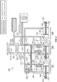
- Figure 2 illustrates a schematic representation of a hydraulic system 200 configured to control main landing gear of an aircraft, in accordance with an example implementation.
- the hydraulic system 200 controls the main landing gear 104 or the main landing gear 106 of the aircraft 100.
- the hydraulic system 200 includes a cylinder (e.g., cylinder 222 described below) having a chamber (e.g., the chamber 230 described below).
- the hydraulic system 200 also includes a flow control valve (e.g., the flow control valve 214) fluidly coupled to the chamber of the cylinder and configured to control fluid flow to and from the chamber.
- the hydraulic system 200 receives pressurized fluid 201 from a landing gear transfer valve that is fluidly coupled to a source of fluid (e.g., a pump, an accumulator, or another valve from a different part of a hydraulic circuit of the aircraft).
- the pressurized fluid 201 is then provided to an inlet fluid line 202.
- the hydraulic system 200 provides return fluid flow through a return fluid line 204 to the landing gear transfer valve, which then provides the return fluid to a fluid reservoir, or a different part of the hydraulic circuit of the aircraft.
- the hydraulic system 200 includes a landing gear selector valve 206 that is fluidly coupled to the inlet fluid line 202 and the return fluid line 204.
- the landing gear selector valve 206 is configured as a directional control valve.
- the landing gear selector valve 206 is actuatable via an electric actuator (e.g., solenoid actuator), a fluidic actuator, or a mechanical actuator, as examples.
- an electric actuator e.g., solenoid actuator
- the landing gear selector valve 206 has a spool within a valve body and the spool is movable in a first linear direction or a second direction opposite the first direction based on an actuation signal to the landing gear selector valve 206 (e.g., actuation signal to one of two solenoids of an solenoid actuator).
- the landing gear selector valve 206 Based on the direction of movement of the spool, the landing gear selector valve 206 provides pressurized fluid to a fluid line 208 while the return flow is received via a fluid line 210, or the landing gear selector valve 206 provides pressurized fluid to the fluid line 210 while the return flow is received via the fluid line 208.
- the fluid line 208 can be referred to as a down pressure fluid line, whereas the fluid line 210 can be referred to as up pressure fluid line.
- Down pressure refers to the fluid line receiving pressurized fluid when the main landing gear is deployed (moving down from the wheel well in the aircraft in preparation for landing)
- up pressure refers to the fluid line receiving pressurized fluid when the main landing gear is retracted (moving up toward the wheel well in the aircraft after takeoff).
- fluid lines with circles therein represent fluid lines involved in retracting the main landing gear
- the fluid lines with cross-hatching represent fluid lines involved in deploying the main landing gear.
- the hydraulic system 200 includes a volume fuse 212.
- the volume fuse 212 is configured to allow a particular amount of fluid volume to pass therethrough in a single operative cycle. If such amount of fluid volume is exceeded, the volume fuse 212 shuts off fluid flow. In this example, the volume fuse 212 protects the hydraulic system 200 from line rupture in the hydraulic system 200 as described below, while resetting after every operative cycle when less than the predetermined volume flows therethrough.
- the hydraulic system 200 also includes a flow control valve 214, which can be referred to as a flow regulator, configured to control fluid flow rate provided to and discharged from a main landing gear actuator 216.
- the flow control valve 214 is fluidly coupled to a transfer cylinder 218 and a frangible fitting 220.
- the frangible fitting 220 works with the volume fuse 212 to provide a safety feature for the hydraulic system 200
- the transfer cylinder 218 is configured as a time delay element to allow a locking mechanism of the main landing gear to be released prior to deploying or retracting the main landing gear.
- the main landing gear actuator 216 includes a cylinder 222 and a piston 224 slidably accommodated within the cylinder 222.
- the term "slidably accommodated” is used herein to indicate that a first component (e.g., the piston 224) is positioned relative to a second component (e.g., the cylinder 222) such that the first component is able to move relative to the second component.
- the piston 224 includes a piston head 226 and a piston rod 228 extending from the piston head 226 along a central longitudinal axis direction of the cylinder 222.
- the piston head 226 divides the inside or internal space of the cylinder 222 into a chamber 230 and a chamber 232.
- the chamber 230 can be referred to as a cap chamber or head chamber, whereas the chamber 232 can be referred to as a rod chamber.
- the piston rod 228 is configured to be coupled to the main landing gear.
- the end of the piston rod 228 is configured to be coupled to a strut or other mechanism coupled to the wheel assembly of the main landing gear.
- the main landing gear actuator 216 is configured such that when the piston 224 extends (e.g., moves to the left in Figure 2 ), the main landing gear and the wheels are retracted or withdrawn into the wheel well after takeoff. On the other hand, when the piston 224 retracts (e.g., moves to the right in Figure 2 ), the main landing gear and the wheels are deployed from the wheel well in preparation for landing.
- the main landing gear has a locking mechanism that is released prior to allowing the main landing gear to be retracted or deployed.
- the locking mechanism is coupled to and releasable by a downlock actuator 234 and an uplock actuator 236.
- the downlock actuator 234 locks the main landing gear in place when the main landing gear is deployed.
- the downlock actuator 234 is then actuated to release the locking mechanism prior to retracting the main landing gear.
- the uplock actuator 236 locks the main landing gear in place when the main landing gear is retracted in the wheel well.
- the uplock actuator 236 is then actuated to release the locking mechanism prior to deploying the main landing gear.
- the downlock actuator 234 and the uplock actuator 236 are generally configured similar to the main landing gear actuator 216.
- the downlock actuator 234 includes a cylinder 238 and a piston 240 slidably accommodated within the cylinder 238.
- the piston 240 includes a piston head 242 and a piston rod 244 extending from the piston head 242 along a central longitudinal axis direction of the cylinder 238.
- the piston head 242 divides an internal space of the cylinder 238 into a chamber 246 and a chamber 248.
- the uplock actuator 236 includes a cylinder 250 and a piston 252 slidably accommodated within the cylinder 250.
- the piston 252 includes a piston head 254 and a piston rod 256 extending from the piston head 254 along a central longitudinal axis direction of the cylinder 250.
- the piston head 254 divides an internal space of the cylinder 250 into a chamber 257 and a chamber 258.
- the hydraulic system 200 is also illustrated to include other components.
- the hydraulic system 200 includes several restrictor check valves including restrictor check valve 260, restrictor check valve 262, and restrictor check valve 264.
- a restrictor check valve is configured to allow free fluid flow (e.g., with minimal pressure drop) in one direction (in the direction of an arrow depicted in the symbols of the restrictor check valves) while restricting fluid flow in the other direction (where a restrictor is depicted in the symbols of the restrictor check valves).
- the hydraulic system 200 can further include relief valves to release pressurized fluid if pressure level in a particular chamber or fluid line exceeds a particular threshold pressure value.
- the hydraulic system 200 includes a relief valve 266 configured to open and provide a fluid path for fluid in the chamber 246 of the downlock actuator 234 if pressure level of fluid therein exceeds a threshold value.
- the hydraulic system 200 is operable in a first mode of operation associated with extending the piston 224 of the main landing gear actuator 216 (e.g., moving the piston 224 to the left in Figure 2 ), which corresponds to retracting the main landing gear back into the wheel well after takeoff of the aircraft.
- the hydraulic system 200 is operable in a second mode of operation associated with retracting the piston 224 of the main landing gear actuator 216 (e.g., moving the piston 224 to the right in Figure 2 ), which corresponds to deploying the main landing gear from the wheel well in preparation for landing the aircraft.
- the hydraulic system 200 is depicted in Figure 2 with arrows illustrating fluid flow directions in the first mode of operation.
- the landing gear selector valve 206 provides fluid flow to the fluid line 210.
- the fluid line 210 is fluidly coupled to an alternate brake system 268 via a fluid line 270 as depicted in Figure 2 .
- the alternate brake system 268 is configured to become active when a normal brake system of the aircraft is faulty and/or low hydraulic pressure is detected in the normal braking system. As such, if the normal braking system is faulty, pressurized fluid is provided via the fluid line 270 to the alternate brake system 268 to brake the wheels and stop their spinning while retracting the main landing gear, thereby preventing damage to components within the wheel well of the aircraft.
- Pressurized fluid is provided via the fluid line 210 to the volume fuse 212, which allows fluid to flow therethrough as long as the fluid volume does not exceed a particular capacity of the volume fuse 212. Fluid is then provided to the flow control valve 214, which operates to control the amount of fluid flow rate provided to the main landing gear actuator 216 so as to move the piston 224 in a controlled manner, e.g., at a desired speed.
- the transfer cylinder 218 is configured to delay providing fluid to the chamber 230 until the locking mechanism of the main landing gear is released.
- the transfer cylinder 218 is configured as a time-delay element that allows fluid flow to be provided to the downlock actuator 234 to release the locking mechanism of the main landing gear prior to retracting the main landing gear.
- the transfer cylinder 218 includes a piston 272 that divides the inner space of the transfer cylinder 218 into two chambers.
- Fluid is provided to the transfer cylinder 218 from the flow control valve 214 and causes the piston 272 to move (e.g., to the left in Figure 2 ). As long as the piston 272 is moving and fluid is filling the transfer cylinder 218, fluid is not provided to the main landing gear actuator 216. Once the piston 272 reaches the end of its stroke within the transfer cylinder 218, fluid is diverted to the restrictor check valve 262 and the main landing gear actuator 216.
- the locking mechanism As the locking mechanism is released, fluid is provided through the restrictor check valve 262 to the chamber 230 of the main landing gear actuator 216, causing the piston 224 to extend (e.g., move to the left in Figure 2 ), thereby retracting the main landing gear toward the wheel well after takeoff.
- the braking system of the aircraft is configured to brake the wheels and prevent the wheels from spinning prior to reaching the wheel well so as to avoid damage to the wheel well.
- the hydraulic system 200 is configured to stop the main landing gear from retracting further (i.e., stop the piston 224 from extending) as a safety feature to avoid damage to the wheel well.
- the frangible fitting 220 has a lever 274.
- the frangible fitting is configured such that the lever 274 breaks if the wheels of the main landing gear continue to spin as the wheels retract.
- fluid from the flow control valve 214 flows through the frangible fitting 220, then to an outside environment of the hydraulic system 200, e.g., to a low pressure volume, as fluid flows through a path of least resistance.
- the fluid flow rate flowing through the volume fuse 212 can increase and exceed its capacity, and responsively the volume fuse 212 shuts off fluid flow therethrough.
- the hydraulic system 200 is also operable in the second mode of operation associated with retracting the piston 224 of the main landing gear actuator 216 (e.g., moving the piston 224 to the right in Figure 2 ), which corresponds to deploying the main landing gear from the wheel well in preparation for landing the aircraft.
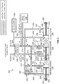
- Figure 3 illustrates the schematic representation of the hydraulic system 200 with arrows illustrating fluid flow directions in the second mode of operation, in accordance with an example implementation.
- the landing gear selector valve 206 provides fluid flow to the fluid line 208.
- Pressurized fluid flowing through the fluid line 208 flows through a fluid line 300 through the restrictor check valve 260, then to the transfer cylinder 218.
- the fluid line 300 is also connected to the chamber 258 of the uplock actuator 236 via a restrictor 302.
- the transfer cylinder 218 operates in a manner similar to its operation in the first mode of operation, but the piston 272 moves in the other direction (e.g., to the right in Figure 3 ). As such, the transfer cylinder 218 operates as a time-delay element that allows fluid flow to be provided to the uplock actuator 236 to release the locking mechanism of the main landing gear prior to deploying the main landing gear. As the piston 272 moves and the fluid provided through the restrictor check valve 260 fills the transfer cylinder 218, fluid is not provided to the chamber 232 of the main landing gear actuator 216. Once the piston 272 reaches the end of its stroke within the transfer cylinder 218, fluid is provided to the chamber 232 of the main landing gear actuator 216.
- Fluid discharged from the chamber 257 as the piston 252 retracts flows through fluid line 304 to a shimmy damper 306 and the return fluid line 204.
- Shimmy is an oscillation in a landing gear that generates undesirable vibration and loads on a structure of the landing gear.
- the shimmy damper 306 dampens oscillations that might occur in movement of the piston 252 to ensure smooth operation of the hydraulic system 200.
- fluid is provided to the chamber 232 of the main landing gear actuator 216, causing the piston 224 to retract (e.g., move to the right in Figure 3 ), thereby deploying the main landing gear from the wheel well in preparation for landing the aircraft.
- Fluid discharged from the chamber 230 as the piston 224 retracts flows through the restrictor check valve 262, then to the flow control valve 214.
- the flow control valve 214 controls the amount of fluid flow rate discharged from the main landing gear actuator 216 so as to move the piston 224 in a controlled manner, e.g., at a desired speed.
- the flow control valve 214 generates a back pressure in the chamber 230 as flow control valve 214 controls fluid flow therethrough, thereby causing the piston 224 to retract in a controlled manner. Fluid exiting the flow control valve 214 flows through the volume fuse 212 and the landing gear selector valve 206 to the return fluid line 204. As such, the flow control valve 214 is configured to cause the piston 224 of the main landing gear actuator 216 to move in a controlled manner.
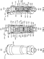
- Figure 4 illustrates a perspective view of the flow control valve 214
- Figure 5 illustrates a cross-sectional view of the flow control valve 214
- Figure 6 illustrates a perspective cross-sectional view of the flow control valve 214, in accordance with an example implementation.
- Figures 4-6 are described together.
- the flow control valve 214 includes a housing 400, a sleeve 412 disposed within the housing 400, and the sleeve 412 has a proximal or first end and a distal or second end opposite the first end.
- the sleeve 412 includes a plurality of sleeve protrusions 700-706 at the first end and a plurality of fluid flow channels 708-714 (e.g., fluid flow channel 708, 710, 712, and 714 for a total of four fluid flow channels) are formed between adjacent sleeve protrusions of the sleeve protrusions 700-706.
- the flow control valve 214 also includes a seal carrier 424 disposed within the sleeve 412, and the seal carrier 424 includes a carrier protrusion 426, 428 that extends from the second end of the sleeve 412 and abuts against an interior surface of the housing 400.
- the flow control valve 214 also includes an end cap 404 mounted to the housing 400 such that the plurality of sleeve protrusions 700-706 abut against the end cap 404.
- the housing 400 is generally cylindrical and having a longitudinal cylindrical cavity defined therein. Components of the flow control valve 214 are disposed in the longitudinal cylindrical cavity of the housing 400.
- the housing 400 has a first port 402 (e.g., an opening) at a distal end 403 of the housing 400.
- the first port 402 allows fluid flow therethrough into and out of the flow control valve 214.
- the first port 402 can be fluidly coupled to the transfer cylinder 218, the frangible fitting 220, and the restrictor check valve 262.
- the end cap 404 is coupled to the housing 400 at a proximal end 401 thereof.
- the end cap 404 is threadedly coupled to the housing 400 via external thread in the end cap 404 and internal threads in the housing 400 at threaded region 406.
- the end cap 404 can keep the flow control valve 214 intact and free of chatter and vibrations that can cause components of the flow control valve 214 to shift internally.
- the end cap 404 has a second port 408 (e.g., an opening) at a proximal end 401 of the flow control valve 214 opposite the first port 402.
- the second port 408 allows fluid flow therethrough into and out of the flow control valve 214.
- the second port 408 can be fluidly coupled to the volume fuse 212.
- the flow control valve 214 is bi-directional and allows fluid flow therethrough from the first port 402 to the second port 408 or from the second port 408 to the first port 402.
- the flow control valve 214 includes a seal 410 (e.g., an O-ring) disposed in in an exterior annular groove formed in the end cap 404 and configured to form a fluid seal between the end cap 404 and the housing 400 to prevent leakage to an outside environment of the flow control valve 214.
- the seal 410 is interposed between backup rings. Backup rings can be used, for example, to reduce the likelihood of extrusion of the seal 410 as pressurization and depressurization/pressure cycling occurs within the flow control valve 214.
- the sleeve 412 is fixedly disposed within the housing 400.
- the sleeve 412 is generally cylindrical and includes a respective longitudinal cylindrical cavity therein.
- Figure 7 illustrates a perspective view of the sleeve 412
- Figure 8 illustrates a cross-sectional view of the sleeve 412, in accordance with an example implementation. Figures 7 and 8 are described together.
- the sleeve 412 has a plurality of sleeve protrusions such as sleeve protrusion 700, sleeve protrusion 702, sleeve protrusion 704, and sleeve protrusion 706 disposed at a proximal end 401 of the sleeve 412.
- the sleeve protrusions 700-706 are disposed in an array such as a circular array as depicted in Figure 7 .
- other array configurations e.g., rectangular array, square array, etc. can be used.
- the sleeve protrusions 700-706 are arcuate in shape. However, in other examples, the sleeve protrusions 700-706 have other shapes, e.g., they can be straight or rectangular. Regardless of the configurations of the sleeve protrusions 700-706, the sleeve protrusions 700-706 form fluid flow channels therebetween, such as fluid flow channel 708, fluid flow channel 710, fluid flow channel 712, and fluid flow channel 714.
- the sleeve 412 includes a hole 716 (e.g., a stepped hole) that defines several steps or shoulders by the interior surface of the sleeve 412 at the proximal end 401 of the sleeve 412 to accommodate other components of the flow control valve 214.
- a hole 716 e.g., a stepped hole
- an internal diameter of the sleeve 412 varies to define cavities therein having different sizes.
- a cavity 718 which is a portion of the hole 716, is configured to receive an orifice plug as described below.
- a shoulder 720 is defined by a transition in the internal diameter of the sleeve 412, and the shoulder 720 is configured to support a spring washer as described below. The shoulder 720 can prohibit a direct flow of fluid from one chamber to another, and directs fluid to flow through the cross-holes, as described below.
- the sleeve 412 includes a first set of cross-holes disposed in an array about a wall of body of the sleeve 412, such as cross-hole 722 and cross-hole 724.
- the first set of cross-holes is disposed in a circular array about the sleeve 412.
- the sleeve 412 further includes a second set of cross-holes also disposed in an array (e.g., a circular array) about the wall of the sleeve 412, such as cross-hole 726 and cross-hole 728.
- the second set of cross-holes is axially-spaced from the first set of cross-hole along a length of the sleeve 412.
- cross-hole is used herein to indicate a hole that crosses a path of, or is formed transverse relative to, another hole, cavity, or channel.
- the sleeve 412 also includes a first flanged portion 730 and a second flanged portion 732 that form a groove 734, e.g., an exterior annular groove, therebetween.
- the exterior surfaces of the first flanged portion 730 and the second flanged portion 732 interface with the interior surface of the housing 400 (as shown in Figures 5-6 ), and the groove 734 is configured to receive a seal and backup rings therein as described below.
- the internal diameter of the sleeve 412 enlarges near its distal end 403 to form a shoulder 736 and a cavity 738.
- the cavity 738 is configured to receive the seal carrier 424, which abuts against the shoulder 736.
- the flow control valve 214 includes an orifice plug 414 disposed in the cavity 718 of the sleeve 412.
- the orifice plug 414 is configured to have an orifice 416 formed therein, e.g., drilled therein, to allow a particular amount of fluid flow rate therethrough.
- the sleeve 412 is disposed within the housing 400 such that a first chamber 418 is formed between the exterior surface of the sleeve 412 and the interior surface of the housing 400.
- a second chamber 420 is formed between the exterior surface of the sleeve 412 and the interior surface of the housing 400.
- the first chamber 418 is separated from the second chamber 420 by way of the flanged portion 730 and the flanged portion 732 of the sleeve 412.
- the flow control valve 214 includes a seal 422 disposed in the groove 734 of the sleeve 412 to seal the first chamber 418 from the second chamber 420.
- Backup rings can be disposed about the seal 422 to reduce the likelihood of extrusion of the seal 422 in the groove 734 of the sleeve 412 as pressurization and de-pressurization/pressure cycling occurs within the flow control valve 214.
- the seal carrier 424 is disposed in the cavity 738 of the sleeve 412. Similar to the sleeve 412, the seal carrier 424 has a plurality of carrier protrusions, such as carrier protrusion 426 and carrier protrusion 428, which form fluid flow channels therebetween such as fluid flow channel 430. As examples, the carrier protrusions 426, 428 are arcuate in shape and are disposed in a circular array. However, other configurations are possible. Further, the seal carrier 424 includes a seal 432 (e.g., an O-ring) disposed in an exterior annular groove formed in the seal carrier 424 and configured to form a fluid seal between the seal carrier 424 and the sleeve 412 to prevent fluid leakage therebetween. Backup rings can be used with the seal 432 as well.
- a seal 432 e.g., an O-ring
- the seal carrier 424 is further configured to receive an orifice plug 434 that is similar to the orifice plug 414.
- the orifice plug 434 has an orifice 436 formed therein to allow a particular amount of fluid flow rate therethrough.
- the sleeve protrusions 700-706 abut against a distal end 403 of the end cap 404. As such, the sleeve 412 is secured axially in the proximal direction via the end cap 404.
- the seal carrier 424 is secured in the proximal direction via the shoulder 736 of the sleeve 412 (see Figure 8 ).
- the carrier protrusions e.g., the carrier protrusions 426, 428, extend from the distal end 403 of the sleeve 412 and abut against an interior surface of the housing 400, and thus the seal carrier 424 is secured axially in the distal direction by the housing 400.
- the sleeve 412 and the seal carrier 424 are longitudinally secured within the housing 400 via their own features (the sleeve and carrier protrusions, and shoulders) and no additional components (e.g., a spacer) are used.
- the flow control valve 214 further includes a spool 438 slidably accommodated and axially-movable within the longitudinal cylindrical cavity of the sleeve 412.
- the spool 438 is hollow and forms a spool shoulder 440, which is a ring-shaped protrusion or annulus, having a hole 442 therethrough.
- the spool 438 is configured to receive a first spring 444 and a second spring 446 therein.
- the first spring 444 has a proximal end 401 resting against a spring washer 448, which in turn rests against the shoulder 720 of the sleeve 412 (see Figure 8 ), whereas a distal end 403 of the first spring 444 rests against one side the spool shoulder 440 of the spool 438.
- a proximal end 401 of the second spring 446 rests against the other side of the spool shoulder 440, whereas a distal end 403 of the second spring 446 rests against a shoulder formed by the seal carrier 424.
- the first spring 444 applies a first spring force on the spool 438 in a distal direction
- the second spring 446 applies a second spring force on the spool 438 in the proximal direction.
- the spring forces maintain the spool 438 in a center position.
- pressure level of fluid at one side of the spool shoulder 440 is different from pressure level of fluid on the other side of the spool shoulder 440, the spool 438 moves axially against the spring force of one of the springs as described below.
- the proximal end 401 of the spool 438 partially overlaps the first set of cross-holes (e.g., the cross-hole 722 and the cross-hole 724), whereas the distal end 403 of the spool 438 partially overlaps the second set of cross-holes (e.g., the cross-hole 726 and the cross-hole 728).
- the second set of cross-holes are restricted further (more of the cross-holes is blocked and the opening sizes of the cross-holes that allow fluid flow decrease), whereas the first set of cross-holes are exposed more (more of the cross-holes is uncovered and the opening sizes of the cross-holes that allow fluid flow increase).
- the first set of cross-holes are restricted further (more of the cross-holes is blocked and the opening sizes of the cross-holes that allow fluid flow decrease), whereas the second set of cross-holes are exposed more (more of the cross-holes is uncovered and the opening sizes of the cross-holes that allow fluid flow increase).
- fluid is received at the second port 408 then flows through the end cap 404 to the proximal end 401 of the sleeve 412. Fluid then flows radially outward through the fluid flow channels of the sleeve 412 (i.e., the fluid flow channels 708-714 shown in Figures 7-8 ) to the first chamber 418. Fluid then flows radially inward through the first set of cross-holes (e.g., the cross-hole 722 and the cross-hole 724) to the spool chamber having the first spring 444 within the spool 438.
- first set of cross-holes e.g., the cross-hole 722 and the cross-hole 724
- Fluid then flows through the hole 442 of the spool shoulder 440 to the spool chamber having the second spring 446.
- a pressure drop occurs (a decrease in pressure level of fluid occurs due to flowing through a fluid restriction caused by the hole 442).
- This pressure drop causes the fluid force acting on the spool 438 in the distal direction to increase relative to the fluid force acting on the spool 438 in the proximal distal direction, causing the spool 438 to move in the distal direction.
- the second spring 446 is compressed and the first spring 444 is relaxed.
- This configuration provides a safety feature where a particular amount of flow is provided through the flow control valve 214 in an event of unexpected issues.
- the safety feature is beneficial, for example, to allow the particular amount of fluid flow through the flow control valve 214 so as to allow the main landing gear actuator 216 to operate despite any issues.
- the spool 438 is biased all the way in one direction by the other spring, thereby completely or substantially blocking the first set of cross-holes (e.g., the cross-hole 722 and the cross-hole 724) or the second set of cross-holes (e.g., the cross-hole 726 and the cross-hole 728).
- first set of cross-holes e.g., the cross-hole 722 and the cross-hole 724
- second set of cross-holes e.g., the cross-hole 726 and the cross-hole 728.
- fluid flowing through the cross-holes to and from the first chamber 418 or the second chamber 420 is blocked.
- fluid flows through the orifice 416 of the orifice plug 414 and the orifice 436 of the orifice plug 434.
- at least a certain amount of a fluid flow is provided through the flow control valve 214 to operate the main landing gear actuator 216.
- the flow control valve 214 has a fluid flow rate capacity of about 8 gallons per minute (GPM).
- a portion of that amount e.g., half or 4 GPM
- the remaining portion e.g., the other half or 4 GPM
- at least 4 GPM are provided from the second port 408 to the first port 402 if any unintended operation occurs within the flow control valve 214.
- the flow control valve 214 is a bi-directional valve as mentioned above and also allows for fluid flow in the other direction, i.e., from the first port 402 to the second port 408. Particularly, fluid is received at the first port 402 then flows radially outward from the fluid flow channels of the seal carrier 424 (e.g., the fluid flow channel 430) to the second chamber 420. Fluid then flows radially inward through the second set of cross-holes (e.g., the cross-hole 726 and the cross-hole 728) to the spool chamber having the second spring 446 within the spool 438.
- the second set of cross-holes e.g., the cross-hole 726 and the cross-hole 72
- Fluid then flows through the hole 442 of the spool shoulder 440 to the spool chamber having the first spring 444.
- a pressure drop occurs. This pressure drop causes the fluid force acting on the spool 438 in the distal direction to increase relative to the fluid force acting on the spool 438 in the proximal distal direction, causing the spool 438 to move in the proximal direction.
- the first spring 444 is compressed and the second spring 446 is relaxed.
- the first set of cross-holes are restricted, whereas the second set of cross-holes are exposed more.
- Fluid in the spring chamber of the first spring 444 flows radially outward through the first set of cross-holes (that are now more restricted) to the first chamber 418. From the first chamber 418, fluid flows radially inward through the fluid flow channels 708-714 of the sleeve 412, then through the second port 408 and out of the flow control valve 214.
- the configuration of the flow control valve 214 can offer several advantages over conventions valves.
- the sleeve 412 is configured as a multi-functional sleeve that integrates features therein instead of having additional components. For instance, rather than using a second seal carrier (in addition to the seal carrier 424) at the proximal end 401 of the sleeve 412, the features of such an additional seal carrier are integrated into the sleeve 412.
- the fluid flow channels 708-714 are integrated in the sleeve 412, the orifice plug 414 is secured within the sleeve 412, and no seal or backup rings are used.
- no seal or backup rings are used.
- a cost and weight of the flow control valve 214 are can be reduced, and also the reliability can be increased by reducing the number of components in operation.
- the sleeve protrusions 700-706 abut the end cap 404, and therefore no additional spacer is used to secure the sleeve 412 axially within the housing 400. As such, another component is eliminated by the multi-functionality of the sleeve 412.
- Figure 9 is a flowchart of a method 900 for assembling the flow control valve 214, in accordance with an example implementation.
- the method 900 includes one or more operations, or actions as illustrated by one or more of blocks 902-916. Although the blocks are illustrated in a sequential order, in example, these blocks are performed in parallel, and/or in a different order than those described herein. Also, in example, the various blocks are combined into fewer blocks, divided into additional blocks, and/or removed based upon the desired implementation. It should be understood that for this and other processes and methods disclosed herein, flowcharts show functionality and operation of one possible implementation of present examples. Alternative implementations are included within the scope of the examples of the present disclosure in which functions are executed out of order from that shown or discussed, including substantially concurrent or in reverse order, depending on the functionality involved, as would be understood by those reasonably skilled in the art.
- the method 900 includes positioning the sleeve 412 within the housing 400, and the sleeve 412 has a first end (e.g., the proximal end 401) and a second end (e.g., the distal end 403) opposite the first end.
- the sleeve 412 includes the sleeve protrusions 700-706 at the first end and the plurality of fluid flow channels 708-714 are formed between adjacent sleeve protrusions, e.g., between the sleeve protrusions 700-706.
- the method 900 includes positioning the seal carrier 424 within the sleeve 412, and the seal carrier 424 includes the carrier protrusion 426, 428 that extends from the second end of the sleeve 412 and abuts against an interior surface of the housing 400.
- the method 900 optionally includes mounting the orifice plug 434 in the cavity of the seal carrier 424, and the orifice plug 434 includes the orifice 436 therein to allow fluid flow therethrough.
- the method 900 optionally includes positioning the spool 438 within the sleeve 412, and the spool 438 is slidably accommodated within the sleeve 412 and includes the spool shoulder 440.
- the method 900 optionally includes mounting the first spring 444 between the spool shoulder 440 and the shoulder 720 of the sleeve 412.
- the method 900 optionally includes mounting the second spring 446 between the spool shoulder 440 and the seal carrier 424.
- the method 900 optionally includes mounting the orifice plug 414 in the cavity 718 of the sleeve 412, and the orifice plug 414 includes the orifice 416 therein to allow fluid flow therethrough.
- the method 900 includes mounting the end cap 404 to the housing 400 such that the sleeve protrusions 700-706 abut against the end cap 404.
- any enumeration of elements, blocks, or steps in this specification or the claims is for purposes of clarity. Thus, such enumeration should not be interpreted to require or imply that these elements, blocks, or steps adhere to a particular arrangement or are carried out in a particular order.
- devices or systems are used or configured to perform functions presented in the figures.
- components of the devices and/or systems are configured to perform the functions such that the components are actually configured and structured (with hardware and/or software) to enable such performance.
- components of the devices and/or systems are arranged to be adapted to, capable of, or suited for performing the functions, such as when operated in a specific manner.
Landscapes
- Engineering & Computer Science (AREA)
- General Engineering & Computer Science (AREA)
- Mechanical Engineering (AREA)
- Physics & Mathematics (AREA)
- Aviation & Aerospace Engineering (AREA)
- Fluid Mechanics (AREA)
- General Physics & Mathematics (AREA)
- Automation & Control Theory (AREA)
- Multiple-Way Valves (AREA)
- Safety Valves (AREA)
- Valve Housings (AREA)
Abstract
Description
- The present disclosure relates generally to a flow control valve having a multi-functional sleeve, and more particularly to a flow control valve that controls fluid flow rate to an actuator to move the actuator in a controlled manner.
- A flow control valve directs the flow of a liquid medium, usually oil, through a hydraulic system and controls fluid flow rate provided to an actuator. An example valve has a movable element, e.g., a spool, inside a housing or sleeve and, based on the spool movement in the sleeve, cross-holes defined on the sleeve are opened and closed to achieve the desired flow rate.
- The present disclosure describes examples that relate to a flow control valve, a method of assembly, and a hydraulic system.
- In one aspect, the present disclosure describes a flow control valve. The flow control valve includes a housing and a sleeve disposed within the housing. The sleeve has a first end and a second end opposite the first end. The sleeve includes a plurality of sleeve protrusions at the first end and a plurality of fluid flow channels are formed between adjacent sleeve protrusions. The flow control valve further includes a seal carrier disposed within the sleeve. The seal carrier includes a carrier protrusion that extends from the second end of the sleeve and abuts against an interior surface of the housing. The flow control valve also includes an end cap mounted to the housing such that the plurality of sleeve protrusions abut against the end cap.
- In another aspect, the present disclosure describes a hydraulic system. The hydraulic system includes a cylinder having a chamber and a flow control valve fluidly coupled to the chamber of the cylinder and configured to control fluid flow to and from the chamber. The flow control valve includes a housing and a sleeve disposed within the housing. The sleeve has a first end and a second end opposite the first end. The sleeve includes a plurality of sleeve protrusions at the first end and a plurality of fluid flow channels are formed between adjacent sleeve protrusion. The flow control valve further includes a seal carrier disposed within the sleeve. The seal carrier includes a carrier protrusion that extends from the second end of the sleeve and abuts against an interior surface of the housing. The flow control valve also includes an end cap mounted to the housing such that the plurality of sleeve protrusions abut against the end cap.
- In still another aspect, the present disclosure describes a method assembling a flow control valve. The method includes positioning a sleeve within a housing. The sleeve has a first end and a second end opposite the first end, and the sleeve includes a plurality of sleeve protrusions at the first end and a plurality of fluid flow channels are formed between adjacent sleeve protrusions. The method also includes positioning a seal carrier within the sleeve. The seal carrier includes a carrier protrusion that extends from the second end of the sleeve and abuts against an interior surface of the housing. The method further includes mounting an end cap to the housing such that the plurality of sleeve protrusions abut against the end cap.
- The foregoing summary is illustrative only and is not intended to be in any way limiting. In addition to the illustrative aspects, examples, and features described above, further aspects, examples, and features will become apparent by reference to the figures and the following detailed description.
- The novel features believed characteristic of the illustrative examples are set forth in the appended claims. The illustrative examples, however, as well as a preferred mode of use, further objectives and descriptions thereof, will best be understood by reference to the following detailed description of an illustrative example of the present disclosure when read in conjunction with the accompanying Figures.
-
Figure 1 illustrates an aircraft having a tricycle landing gear configuration, in accordance with an example implementation. -
Figure 2 illustrates a schematic representation of a hydraulic system configured to control main landing gear of an aircraft, in accordance with an example implementation. -
Figure 3 illustrates the schematic representation of the hydraulic system inFigure 2 with arrows illustrating fluid flow directions in another mode of operation, in accordance with an example implementation. -
Figure 4 illustrates a perspective view of a flow control valve, in accordance with an example implementation. -
Figure 5 illustrates a cross-sectional view of the flow control valve ofFigure 4 , in accordance with an example implementation. -
Figure 6 illustrates a perspective cross-sectional view of the flow control valve ofFigures 4-5 , in accordance with an example implementation. -
Figure 7 illustrates a perspective view of a sleeve, in accordance with an example implementation. -
Figure 8 illustrates a cross-sectional view of the sleeve ofFigure 7 , in accordance with an example implementation. -
Figure 9 is a flowchart of a method for assembling a flow control valve, in accordance with an example implementation. - Within examples, disclosed herein are a flow control valve having a multi-functional sleeve, a hydraulic system, and a method of assembling the flow control valve. The sleeve is disposed within a housing of the flow control valve, and a spool is configured to be slidably accommodated within the sleeve. Based on the spool movement in the sleeve, cross-holes defined by interaction between the spool and the sleeve are opened and closed to achieve the desired flow rate.
- The sleeve is configured to allow fluid flow through fluid flow channels formed in the sleeve. The sleeve further has a slot or cavity to hold an orifice plug rather than using a separate lock nut and orifice plate. This way, additional parts can be eliminated while their features are included in the sleeve. As such, the valve can have a reduced number of parts compared to conventional valves, and may thus have reduced weight and cost.
- Further, the orifice plug integrated with the sleeve can operate as a safety feature, which allows a particular amount of fluid flow rate therethrough (e.g., at least a minimum fluid flow) when a component operates in an unintended manner that blocks the cross-holes. As such, the valve enables operating an actuator in applications despite unintended operation of certain components of the valve. By providing a minimum fluid flow therethrough when a component operates in an unintended manner, the valves enables movement of the actuator to a safe position in some applications. An example application in which the valve can be used is the hydraulic system configured to control operation of a main landing gear of an aircraft. However, it should be understood that the flow control valve disclosed herein can be used with other types of actuators and applications.
-
Figure 1 illustrates anaircraft 100 having a tricycle landing gear configuration, in accordance with an example implementation. The tricycle landing gear configuration includes a type of aircraft landing gear in which a single nose wheel is positioned at a front of theaircraft 100 and two main wheels are positioned slightly aft of a center of gravity of theaircraft 100. For example, theaircraft 100 has anose landing gear 102 having a wheel in the front. Theaircraft 100 also has two main landing gears,main landing gear 104 andmain landing gear 106, with associated wheels slightly aft of the center of gravity of theaircraft 100. - The
main landing gear 104, for example, includes an actuator, such as an actuator 216 (shown inFigure 2 ), having a piston axially-movable within a cylinder and configured to deploy the wheels during landing and retract the wheels in a wheel well after takeoff of theaircraft 100. Within examples, the actuator is operated in a controlled manner by controlling the amount of fluid flow rate provided to the actuator to move the piston at a particular desired speed, and to enable the actuator to operate and deploy or retract themain landing gear 104 in a safe manner. Themain landing gear 106 is configured in a similar manner. An example hydraulic system described below is configured to control the actuator of a main landing gear such as themain landing gear 104 or themain landing gear 106. -
Figure 2 illustrates a schematic representation of ahydraulic system 200 configured to control main landing gear of an aircraft, in accordance with an example implementation. For example, thehydraulic system 200 controls themain landing gear 104 or themain landing gear 106 of theaircraft 100. - The
hydraulic system 200 includes a cylinder (e.g.,cylinder 222 described below) having a chamber (e.g., thechamber 230 described below). Thehydraulic system 200 also includes a flow control valve (e.g., the flow control valve 214) fluidly coupled to the chamber of the cylinder and configured to control fluid flow to and from the chamber. - An example configuration of the
flow control valve 214 is described below with respect toFigures 4-8 . In examples, thehydraulic system 200 includes other components as described below. - The
hydraulic system 200 receives pressurized fluid 201 from a landing gear transfer valve that is fluidly coupled to a source of fluid (e.g., a pump, an accumulator, or another valve from a different part of a hydraulic circuit of the aircraft). Thepressurized fluid 201 is then provided to aninlet fluid line 202. Thehydraulic system 200 provides return fluid flow through areturn fluid line 204 to the landing gear transfer valve, which then provides the return fluid to a fluid reservoir, or a different part of the hydraulic circuit of the aircraft. - The
hydraulic system 200 includes a landinggear selector valve 206 that is fluidly coupled to theinlet fluid line 202 and thereturn fluid line 204. In an example, the landinggear selector valve 206 is configured as a directional control valve. - The landing
gear selector valve 206 is actuatable via an electric actuator (e.g., solenoid actuator), a fluidic actuator, or a mechanical actuator, as examples. For instance, the landinggear selector valve 206 has a spool within a valve body and the spool is movable in a first linear direction or a second direction opposite the first direction based on an actuation signal to the landing gear selector valve 206 (e.g., actuation signal to one of two solenoids of an solenoid actuator). Based on the direction of movement of the spool, the landinggear selector valve 206 provides pressurized fluid to afluid line 208 while the return flow is received via afluid line 210, or the landinggear selector valve 206 provides pressurized fluid to thefluid line 210 while the return flow is received via thefluid line 208. - The
fluid line 208 can be referred to as a down pressure fluid line, whereas thefluid line 210 can be referred to as up pressure fluid line. "Down pressure" refers to the fluid line receiving pressurized fluid when the main landing gear is deployed (moving down from the wheel well in the aircraft in preparation for landing), whereas "up pressure" refers to the fluid line receiving pressurized fluid when the main landing gear is retracted (moving up toward the wheel well in the aircraft after takeoff). As illustrated by the key ofFigure 2 , fluid lines with circles therein represent fluid lines involved in retracting the main landing gear, and the fluid lines with cross-hatching represent fluid lines involved in deploying the main landing gear. - The
hydraulic system 200 includes avolume fuse 212. Thevolume fuse 212 is configured to allow a particular amount of fluid volume to pass therethrough in a single operative cycle. If such amount of fluid volume is exceeded, thevolume fuse 212 shuts off fluid flow. In this example, thevolume fuse 212 protects thehydraulic system 200 from line rupture in thehydraulic system 200 as described below, while resetting after every operative cycle when less than the predetermined volume flows therethrough. - The
hydraulic system 200 also includes aflow control valve 214, which can be referred to as a flow regulator, configured to control fluid flow rate provided to and discharged from a mainlanding gear actuator 216. Theflow control valve 214 is fluidly coupled to atransfer cylinder 218 and afrangible fitting 220. As descried below, thefrangible fitting 220 works with thevolume fuse 212 to provide a safety feature for thehydraulic system 200, and thetransfer cylinder 218 is configured as a time delay element to allow a locking mechanism of the main landing gear to be released prior to deploying or retracting the main landing gear. - The main
landing gear actuator 216 includes acylinder 222 and apiston 224 slidably accommodated within thecylinder 222. The term "slidably accommodated" is used herein to indicate that a first component (e.g., the piston 224) is positioned relative to a second component (e.g., the cylinder 222) such that the first component is able to move relative to the second component. - The
piston 224 includes apiston head 226 and apiston rod 228 extending from thepiston head 226 along a central longitudinal axis direction of thecylinder 222. Thepiston head 226 divides the inside or internal space of thecylinder 222 into achamber 230 and achamber 232. Thechamber 230 can be referred to as a cap chamber or head chamber, whereas thechamber 232 can be referred to as a rod chamber. - The
piston rod 228 is configured to be coupled to the main landing gear. For example, the end of thepiston rod 228 is configured to be coupled to a strut or other mechanism coupled to the wheel assembly of the main landing gear. The mainlanding gear actuator 216 is configured such that when thepiston 224 extends (e.g., moves to the left inFigure 2 ), the main landing gear and the wheels are retracted or withdrawn into the wheel well after takeoff. On the other hand, when thepiston 224 retracts (e.g., moves to the right inFigure 2 ), the main landing gear and the wheels are deployed from the wheel well in preparation for landing. - As mentioned above, the main landing gear has a locking mechanism that is released prior to allowing the main landing gear to be retracted or deployed. The locking mechanism is coupled to and releasable by a
downlock actuator 234 and anuplock actuator 236. For example, thedownlock actuator 234 locks the main landing gear in place when the main landing gear is deployed. Thedownlock actuator 234 is then actuated to release the locking mechanism prior to retracting the main landing gear. On the other hand, theuplock actuator 236 locks the main landing gear in place when the main landing gear is retracted in the wheel well. Theuplock actuator 236 is then actuated to release the locking mechanism prior to deploying the main landing gear. - The
downlock actuator 234 and theuplock actuator 236 are generally configured similar to the mainlanding gear actuator 216. Thedownlock actuator 234 includes acylinder 238 and apiston 240 slidably accommodated within thecylinder 238. Thepiston 240 includes apiston head 242 and apiston rod 244 extending from thepiston head 242 along a central longitudinal axis direction of thecylinder 238. Thepiston head 242 divides an internal space of thecylinder 238 into achamber 246 and achamber 248. - Similarly, the
uplock actuator 236 includes acylinder 250 and apiston 252 slidably accommodated within thecylinder 250. Thepiston 252 includes apiston head 254 and apiston rod 256 extending from thepiston head 254 along a central longitudinal axis direction of thecylinder 250. Thepiston head 254 divides an internal space of thecylinder 250 into achamber 257 and achamber 258. - The
hydraulic system 200 is also illustrated to include other components. For example, thehydraulic system 200 includes several restrictor check valves includingrestrictor check valve 260,restrictor check valve 262, andrestrictor check valve 264. A restrictor check valve is configured to allow free fluid flow (e.g., with minimal pressure drop) in one direction (in the direction of an arrow depicted in the symbols of the restrictor check valves) while restricting fluid flow in the other direction (where a restrictor is depicted in the symbols of the restrictor check valves). - The
hydraulic system 200 can further include relief valves to release pressurized fluid if pressure level in a particular chamber or fluid line exceeds a particular threshold pressure value. For example, thehydraulic system 200 includes arelief valve 266 configured to open and provide a fluid path for fluid in thechamber 246 of thedownlock actuator 234 if pressure level of fluid therein exceeds a threshold value. - The
hydraulic system 200 is operable in a first mode of operation associated with extending thepiston 224 of the main landing gear actuator 216 (e.g., moving thepiston 224 to the left inFigure 2 ), which corresponds to retracting the main landing gear back into the wheel well after takeoff of the aircraft. Thehydraulic system 200 is operable in a second mode of operation associated with retracting thepiston 224 of the main landing gear actuator 216 (e.g., moving thepiston 224 to the right inFigure 2 ), which corresponds to deploying the main landing gear from the wheel well in preparation for landing the aircraft. - The
hydraulic system 200 is depicted inFigure 2 with arrows illustrating fluid flow directions in the first mode of operation. In this first mode of operation, the landinggear selector valve 206 provides fluid flow to thefluid line 210. In an example, thefluid line 210 is fluidly coupled to analternate brake system 268 via afluid line 270 as depicted inFigure 2 . Thealternate brake system 268 is configured to become active when a normal brake system of the aircraft is faulty and/or low hydraulic pressure is detected in the normal braking system. As such, if the normal braking system is faulty, pressurized fluid is provided via thefluid line 270 to thealternate brake system 268 to brake the wheels and stop their spinning while retracting the main landing gear, thereby preventing damage to components within the wheel well of the aircraft. - Pressurized fluid is provided via the
fluid line 210 to thevolume fuse 212, which allows fluid to flow therethrough as long as the fluid volume does not exceed a particular capacity of thevolume fuse 212. Fluid is then provided to theflow control valve 214, which operates to control the amount of fluid flow rate provided to the mainlanding gear actuator 216 so as to move thepiston 224 in a controlled manner, e.g., at a desired speed. - Fluid passing through the
flow control valve 214 then flows to thetransfer cylinder 218. Thetransfer cylinder 218 is configured to delay providing fluid to thechamber 230 until the locking mechanism of the main landing gear is released. Particularly, thetransfer cylinder 218 is configured as a time-delay element that allows fluid flow to be provided to thedownlock actuator 234 to release the locking mechanism of the main landing gear prior to retracting the main landing gear. For example, thetransfer cylinder 218 includes apiston 272 that divides the inner space of thetransfer cylinder 218 into two chambers. - Fluid is provided to the
transfer cylinder 218 from theflow control valve 214 and causes thepiston 272 to move (e.g., to the left inFigure 2 ). As long as thepiston 272 is moving and fluid is filling thetransfer cylinder 218, fluid is not provided to the mainlanding gear actuator 216. Once thepiston 272 reaches the end of its stroke within thetransfer cylinder 218, fluid is diverted to therestrictor check valve 262 and the mainlanding gear actuator 216. - While the
piston 272 of thetransfer cylinder 218 is moving, fluid is being provided from thevolume fuse 212 through a restrictor 273 to thechamber 246 of thedownlock actuator 234. Fluid provided to thechamber 246 causes thepiston 240 to extend (e.g., move to the left inFigure 2 ). As thepiston 272 of thetransfer cylinder 218 reaches the end of its stroke, thepiston 240 has also extended sufficiently to release the locking mechanism and allow the main landing gear to retract. - As the locking mechanism is released, fluid is provided through the
restrictor check valve 262 to thechamber 230 of the mainlanding gear actuator 216, causing thepiston 224 to extend (e.g., move to the left inFigure 2 ), thereby retracting the main landing gear toward the wheel well after takeoff. The braking system of the aircraft is configured to brake the wheels and prevent the wheels from spinning prior to reaching the wheel well so as to avoid damage to the wheel well. In an instance where the wheels keep spinning, thehydraulic system 200 is configured to stop the main landing gear from retracting further (i.e., stop thepiston 224 from extending) as a safety feature to avoid damage to the wheel well. - In particular, the
frangible fitting 220 has alever 274. The frangible fitting is configured such that thelever 274 breaks if the wheels of the main landing gear continue to spin as the wheels retract. When thelever 274 breaks, fluid from theflow control valve 214 flows through thefrangible fitting 220, then to an outside environment of thehydraulic system 200, e.g., to a low pressure volume, as fluid flows through a path of least resistance. As a result, the fluid flow rate flowing through thevolume fuse 212 can increase and exceed its capacity, and responsively thevolume fuse 212 shuts off fluid flow therethrough. - This way, fluid is not provided to the
flow control valve 214 and thepiston 224 stops extending to preclude the main landing gear from retracting further. However, thepiston 224 is allowed to retract so as to cause the main landing gear to deploy and the aircraft to land safely. - As mentioned above, the
hydraulic system 200 is also operable in the second mode of operation associated with retracting thepiston 224 of the main landing gear actuator 216 (e.g., moving thepiston 224 to the right inFigure 2 ), which corresponds to deploying the main landing gear from the wheel well in preparation for landing the aircraft. -
Figure 3 illustrates the schematic representation of thehydraulic system 200 with arrows illustrating fluid flow directions in the second mode of operation, in accordance with an example implementation. In this second mode of operation, the landinggear selector valve 206 provides fluid flow to thefluid line 208. Pressurized fluid flowing through thefluid line 208 flows through afluid line 300 through therestrictor check valve 260, then to thetransfer cylinder 218. As depicted inFigure 3 , thefluid line 300 is also connected to thechamber 258 of theuplock actuator 236 via arestrictor 302. - The
transfer cylinder 218 operates in a manner similar to its operation in the first mode of operation, but thepiston 272 moves in the other direction (e.g., to the right inFigure 3 ). As such, thetransfer cylinder 218 operates as a time-delay element that allows fluid flow to be provided to theuplock actuator 236 to release the locking mechanism of the main landing gear prior to deploying the main landing gear. As thepiston 272 moves and the fluid provided through therestrictor check valve 260 fills thetransfer cylinder 218, fluid is not provided to thechamber 232 of the mainlanding gear actuator 216. Once thepiston 272 reaches the end of its stroke within thetransfer cylinder 218, fluid is provided to thechamber 232 of the mainlanding gear actuator 216. - While the
piston 272 of thetransfer cylinder 218 is moving, fluid is being provided from thefluid line 300 through the restrictor 302 to thechamber 258 of theuplock actuator 236. Fluid provided to thechamber 258 causes thepiston 252 to retract (e.g., move to the left inFigure 3 ). As thepiston 272 of thetransfer cylinder 218 reaches the end of its stroke, thepiston 252 has also extended sufficiently to release the locking mechanism and allow the main landing gear to deploy. - Fluid discharged from the
chamber 257 as thepiston 252 retracts flows throughfluid line 304 to ashimmy damper 306 and thereturn fluid line 204. Shimmy is an oscillation in a landing gear that generates undesirable vibration and loads on a structure of the landing gear. Theshimmy damper 306 dampens oscillations that might occur in movement of thepiston 252 to ensure smooth operation of thehydraulic system 200. - As the locking mechanism is released, fluid is provided to the
chamber 232 of the mainlanding gear actuator 216, causing thepiston 224 to retract (e.g., move to the right inFigure 3 ), thereby deploying the main landing gear from the wheel well in preparation for landing the aircraft. Fluid discharged from thechamber 230 as thepiston 224 retracts flows through therestrictor check valve 262, then to theflow control valve 214. Theflow control valve 214 controls the amount of fluid flow rate discharged from the mainlanding gear actuator 216 so as to move thepiston 224 in a controlled manner, e.g., at a desired speed. - Particularly, the
flow control valve 214 generates a back pressure in thechamber 230 asflow control valve 214 controls fluid flow therethrough, thereby causing thepiston 224 to retract in a controlled manner. Fluid exiting theflow control valve 214 flows through thevolume fuse 212 and the landinggear selector valve 206 to thereturn fluid line 204. As such, theflow control valve 214 is configured to cause thepiston 224 of the mainlanding gear actuator 216 to move in a controlled manner. -
Figure 4 illustrates a perspective view of theflow control valve 214,Figure 5 illustrates a cross-sectional view of theflow control valve 214, andFigure 6 illustrates a perspective cross-sectional view of theflow control valve 214, in accordance with an example implementation.Figures 4-6 are described together. - The
flow control valve 214 includes ahousing 400, asleeve 412 disposed within thehousing 400, and thesleeve 412 has a proximal or first end and a distal or second end opposite the first end. Thesleeve 412 includes a plurality of sleeve protrusions 700-706 at the first end and a plurality of fluid flow channels 708-714 (e.g.,fluid flow channel flow control valve 214 also includes aseal carrier 424 disposed within thesleeve 412, and theseal carrier 424 includes acarrier protrusion sleeve 412 and abuts against an interior surface of thehousing 400. Theflow control valve 214 also includes anend cap 404 mounted to thehousing 400 such that the plurality of sleeve protrusions 700-706 abut against theend cap 404. - The
housing 400 is generally cylindrical and having a longitudinal cylindrical cavity defined therein. Components of theflow control valve 214 are disposed in the longitudinal cylindrical cavity of thehousing 400. Thehousing 400 has a first port 402 (e.g., an opening) at adistal end 403 of thehousing 400. Thefirst port 402 allows fluid flow therethrough into and out of theflow control valve 214. For instance, thefirst port 402 can be fluidly coupled to thetransfer cylinder 218, thefrangible fitting 220, and therestrictor check valve 262. - The
end cap 404 is coupled to thehousing 400 at aproximal end 401 thereof. For example, theend cap 404 is threadedly coupled to thehousing 400 via external thread in theend cap 404 and internal threads in thehousing 400 at threadedregion 406. Theend cap 404 can keep theflow control valve 214 intact and free of chatter and vibrations that can cause components of theflow control valve 214 to shift internally. - The
end cap 404 has a second port 408 (e.g., an opening) at aproximal end 401 of theflow control valve 214 opposite thefirst port 402. Thesecond port 408 allows fluid flow therethrough into and out of theflow control valve 214. For instance, thesecond port 408 can be fluidly coupled to thevolume fuse 212. Theflow control valve 214 is bi-directional and allows fluid flow therethrough from thefirst port 402 to thesecond port 408 or from thesecond port 408 to thefirst port 402. - The
flow control valve 214 includes a seal 410 (e.g., an O-ring) disposed in in an exterior annular groove formed in theend cap 404 and configured to form a fluid seal between theend cap 404 and thehousing 400 to prevent leakage to an outside environment of theflow control valve 214. In an example, theseal 410 is interposed between backup rings. Backup rings can be used, for example, to reduce the likelihood of extrusion of theseal 410 as pressurization and depressurization/pressure cycling occurs within theflow control valve 214. - The
sleeve 412 is fixedly disposed within thehousing 400. Thesleeve 412 is generally cylindrical and includes a respective longitudinal cylindrical cavity therein. -
Figure 7 illustrates a perspective view of thesleeve 412, andFigure 8 illustrates a cross-sectional view of thesleeve 412, in accordance with an example implementation.Figures 7 and 8 are described together. - The
sleeve 412 has a plurality of sleeve protrusions such assleeve protrusion 700,sleeve protrusion 702,sleeve protrusion 704, andsleeve protrusion 706 disposed at aproximal end 401 of thesleeve 412. In an example, the sleeve protrusions 700-706 are disposed in an array such as a circular array as depicted inFigure 7 . However, other array configurations (e.g., rectangular array, square array, etc.) can be used. - Further, in examples as depicted in
Figure 7 , the sleeve protrusions 700-706 are arcuate in shape. However, in other examples, the sleeve protrusions 700-706 have other shapes, e.g., they can be straight or rectangular. Regardless of the configurations of the sleeve protrusions 700-706, the sleeve protrusions 700-706 form fluid flow channels therebetween, such asfluid flow channel 708,fluid flow channel 710,fluid flow channel 712, andfluid flow channel 714. - The
sleeve 412 includes a hole 716 (e.g., a stepped hole) that defines several steps or shoulders by the interior surface of thesleeve 412 at theproximal end 401 of thesleeve 412 to accommodate other components of theflow control valve 214. In other words, an internal diameter of thesleeve 412 varies to define cavities therein having different sizes. For example, acavity 718, which is a portion of thehole 716, is configured to receive an orifice plug as described below. Ashoulder 720 is defined by a transition in the internal diameter of thesleeve 412, and theshoulder 720 is configured to support a spring washer as described below. Theshoulder 720 can prohibit a direct flow of fluid from one chamber to another, and directs fluid to flow through the cross-holes, as described below. - The
sleeve 412 includes a first set of cross-holes disposed in an array about a wall of body of thesleeve 412, such ascross-hole 722 and cross-hole 724. For example, the first set of cross-holes is disposed in a circular array about thesleeve 412. Thesleeve 412 further includes a second set of cross-holes also disposed in an array (e.g., a circular array) about the wall of thesleeve 412, such ascross-hole 726 and cross-hole 728. The second set of cross-holes is axially-spaced from the first set of cross-hole along a length of thesleeve 412. The term "cross-hole" is used herein to indicate a hole that crosses a path of, or is formed transverse relative to, another hole, cavity, or channel. - The
sleeve 412 also includes a firstflanged portion 730 and a secondflanged portion 732 that form agroove 734, e.g., an exterior annular groove, therebetween. The exterior surfaces of the firstflanged portion 730 and the secondflanged portion 732 interface with the interior surface of the housing 400 (as shown inFigures 5-6 ), and thegroove 734 is configured to receive a seal and backup rings therein as described below. - As depicted in
Figure 8 , the internal diameter of thesleeve 412 enlarges near itsdistal end 403 to form ashoulder 736 and acavity 738. Thecavity 738 is configured to receive theseal carrier 424, which abuts against theshoulder 736. - Referring to
Figures 5-6 along withFigures 7-8 , theflow control valve 214 includes anorifice plug 414 disposed in thecavity 718 of thesleeve 412. Theorifice plug 414 is configured to have anorifice 416 formed therein, e.g., drilled therein, to allow a particular amount of fluid flow rate therethrough. - As shown in
Figures 5-6 , thesleeve 412 is disposed within thehousing 400 such that afirst chamber 418 is formed between the exterior surface of thesleeve 412 and the interior surface of thehousing 400. Similarly, asecond chamber 420 is formed between the exterior surface of thesleeve 412 and the interior surface of thehousing 400. Thefirst chamber 418 is separated from thesecond chamber 420 by way of theflanged portion 730 and theflanged portion 732 of thesleeve 412. - Further, the
flow control valve 214 includes aseal 422 disposed in thegroove 734 of thesleeve 412 to seal thefirst chamber 418 from thesecond chamber 420. Backup rings can be disposed about theseal 422 to reduce the likelihood of extrusion of theseal 422 in thegroove 734 of thesleeve 412 as pressurization and de-pressurization/pressure cycling occurs within theflow control valve 214. - The
seal carrier 424 is disposed in thecavity 738 of thesleeve 412. Similar to thesleeve 412, theseal carrier 424 has a plurality of carrier protrusions, such ascarrier protrusion 426 andcarrier protrusion 428, which form fluid flow channels therebetween such asfluid flow channel 430. As examples, thecarrier protrusions seal carrier 424 includes a seal 432 (e.g., an O-ring) disposed in an exterior annular groove formed in theseal carrier 424 and configured to form a fluid seal between theseal carrier 424 and thesleeve 412 to prevent fluid leakage therebetween. Backup rings can be used with theseal 432 as well. - The
seal carrier 424 is further configured to receive anorifice plug 434 that is similar to theorifice plug 414. Theorifice plug 434 has anorifice 436 formed therein to allow a particular amount of fluid flow rate therethrough. - As shown in
Figures 5-6 , the sleeve protrusions 700-706 abut against adistal end 403 of theend cap 404. As such, thesleeve 412 is secured axially in the proximal direction via theend cap 404. - Further, the
seal carrier 424 is secured in the proximal direction via theshoulder 736 of the sleeve 412 (seeFigure 8 ). Also, the carrier protrusions (e.g., thecarrier protrusions 426, 428) extend from thedistal end 403 of thesleeve 412 and abut against an interior surface of thehousing 400, and thus theseal carrier 424 is secured axially in the distal direction by thehousing 400. With this configuration, thesleeve 412 and theseal carrier 424 are longitudinally secured within thehousing 400 via their own features (the sleeve and carrier protrusions, and shoulders) and no additional components (e.g., a spacer) are used. - The
flow control valve 214 further includes aspool 438 slidably accommodated and axially-movable within the longitudinal cylindrical cavity of thesleeve 412. Thespool 438 is hollow and forms aspool shoulder 440, which is a ring-shaped protrusion or annulus, having ahole 442 therethrough. - Also, as shown in
Figures 5-6 , thespool 438 is configured to receive afirst spring 444 and asecond spring 446 therein. Particularly, thefirst spring 444 has aproximal end 401 resting against aspring washer 448, which in turn rests against theshoulder 720 of the sleeve 412 (seeFigure 8 ), whereas adistal end 403 of thefirst spring 444 rests against one side thespool shoulder 440 of thespool 438. On the other hand, aproximal end 401 of thesecond spring 446 rests against the other side of thespool shoulder 440, whereas adistal end 403 of thesecond spring 446 rests against a shoulder formed by theseal carrier 424. - With this configuration, the
first spring 444 applies a first spring force on thespool 438 in a distal direction, and thesecond spring 446 applies a second spring force on thespool 438 in the proximal direction. The spring forces maintain thespool 438 in a center position. However, if pressure level of fluid at one side of thespool shoulder 440 is different from pressure level of fluid on the other side of thespool shoulder 440, thespool 438 moves axially against the spring force of one of the springs as described below. - When the
spool 438 is in the centered position shown inFigures 5-6 , theproximal end 401 of thespool 438 partially overlaps the first set of cross-holes (e.g., the cross-hole 722 and the cross-hole 724), whereas thedistal end 403 of thespool 438 partially overlaps the second set of cross-holes (e.g., the cross-hole 726 and the cross-hole 728). If thespool 438 moves in a distal direction, the second set of cross-holes are restricted further (more of the cross-holes is blocked and the opening sizes of the cross-holes that allow fluid flow decrease), whereas the first set of cross-holes are exposed more (more of the cross-holes is uncovered and the opening sizes of the cross-holes that allow fluid flow increase). - On the other hand, if the
spool 438 moves in a proximal direction, the first set of cross-holes are restricted further (more of the cross-holes is blocked and the opening sizes of the cross-holes that allow fluid flow decrease), whereas the second set of cross-holes are exposed more (more of the cross-holes is uncovered and the opening sizes of the cross-holes that allow fluid flow increase). With this configuration, as thespool 438 moves axially within thesleeve 412, fluid flow rate and pressure levels are modulated during operation. - For example, if the direction of fluid flow is from the
second port 408 to thefirst port 402, fluid is received at thesecond port 408 then flows through theend cap 404 to theproximal end 401 of thesleeve 412. Fluid then flows radially outward through the fluid flow channels of the sleeve 412 (i.e., the fluid flow channels 708-714 shown inFigures 7-8 ) to thefirst chamber 418. Fluid then flows radially inward through the first set of cross-holes (e.g., the cross-hole 722 and the cross-hole 724) to the spool chamber having thefirst spring 444 within thespool 438. - Fluid then flows through the
hole 442 of thespool shoulder 440 to the spool chamber having thesecond spring 446. As fluid flows through thehole 442, a pressure drop occurs (a decrease in pressure level of fluid occurs due to flowing through a fluid restriction caused by the hole 442). This pressure drop causes the fluid force acting on thespool 438 in the distal direction to increase relative to the fluid force acting on thespool 438 in the proximal distal direction, causing thespool 438 to move in the distal direction. As thespool 438 moves in the distal direction, thesecond spring 446 is compressed and thefirst spring 444 is relaxed. - Further, as the
spool 438 moves in the distal direction, the second set of cross-holes are restricted, whereas the first set of cross-holes are exposed more. Fluid in the spring chamber of thesecond spring 446 flows radially outward through the second set of cross-holes (that are now more restricted) to thesecond chamber 420. From thesecond chamber 420, fluid flows radially inward through the fluid flow channels of the seal carrier 424 (e.g., the fluid flow channel 430), then through thefirst port 402 and out of theflow control valve 214. - While a portion of the fluid received at the
second port 408 flows through the above-described path (i.e., through the fluid flow channels, the annular chambers between thesleeve 412 and thehousing 400, the sets of cross-holes), another portion of the fluid flows through theorifice plug 414 and theorifice 416, then through theorifice plug 434 and theorifice 436 to thefirst port 402 and out of theflow control valve 214. This configuration provides a safety feature where a particular amount of flow is provided through theflow control valve 214 in an event of unexpected issues. The safety feature is beneficial, for example, to allow the particular amount of fluid flow through theflow control valve 214 so as to allow the mainlanding gear actuator 216 to operate despite any issues. - Particularly, if the
first spring 444 or thesecond spring 446 does not operate as intended, thespool 438 is biased all the way in one direction by the other spring, thereby completely or substantially blocking the first set of cross-holes (e.g., the cross-hole 722 and the cross-hole 724) or the second set of cross-holes (e.g., the cross-hole 726 and the cross-hole 728). As a result, fluid flowing through the cross-holes to and from thefirst chamber 418 or thesecond chamber 420 is blocked. However, fluid flows through theorifice 416 of theorifice plug 414 and theorifice 436 of theorifice plug 434. In this example, at least a certain amount of a fluid flow is provided through theflow control valve 214 to operate the mainlanding gear actuator 216. - As an example for illustration, the
flow control valve 214 has a fluid flow rate capacity of about 8 gallons per minute (GPM). A portion of that amount (e.g., half or 4 GPM) flows through the fluid flow channels 708-714, thefirst chamber 418, the first set of cross-holes, the second set of cross-holes, thesecond chamber 420, and the fluid flow channels of the seal carrier 424 (e.g., the fluid flow channel 430). The remaining portion (e.g., the other half or 4 GPM) flows through theorifice 416 and theorifice 436. In this example, at least 4 GPM are provided from thesecond port 408 to thefirst port 402 if any unintended operation occurs within theflow control valve 214. - The
flow control valve 214 is a bi-directional valve as mentioned above and also allows for fluid flow in the other direction, i.e., from thefirst port 402 to thesecond port 408. Particularly, fluid is received at thefirst port 402 then flows radially outward from the fluid flow channels of the seal carrier 424 (e.g., the fluid flow channel 430) to thesecond chamber 420. Fluid then flows radially inward through the second set of cross-holes (e.g., the cross-hole 726 and the cross-hole 728) to the spool chamber having thesecond spring 446 within thespool 438. - Fluid then flows through the
hole 442 of thespool shoulder 440 to the spool chamber having thefirst spring 444. As fluid flows through thehole 442, a pressure drop occurs. This pressure drop causes the fluid force acting on thespool 438 in the distal direction to increase relative to the fluid force acting on thespool 438 in the proximal distal direction, causing thespool 438 to move in the proximal direction. As thespool 438 moves in the proximal direction, thefirst spring 444 is compressed and thesecond spring 446 is relaxed. - Further, as the
spool 438 moves in the proximal direction, the first set of cross-holes are restricted, whereas the second set of cross-holes are exposed more. Fluid in the spring chamber of thefirst spring 444 flows radially outward through the first set of cross-holes (that are now more restricted) to thefirst chamber 418. From thefirst chamber 418, fluid flows radially inward through the fluid flow channels 708-714 of thesleeve 412, then through thesecond port 408 and out of theflow control valve 214. - While a portion of the fluid received at the
first port 402 flows through the above-described path (i.e., through the fluid flow channels, the annular chambers, the sets of cross-holes), another portion of the fluid flows through theorifice plug 434 and theorifice 436, then through theorifice plug 414 and theorifice 416 to thesecond port 408 and out of theflow control valve 214. This configuration provides a safety feature where a particular amount of flow is provided through theflow control valve 214 if any unintended operation occurs as described above. - Within examples, the configuration of the
flow control valve 214 can offer several advantages over conventions valves. For example, thesleeve 412 is configured as a multi-functional sleeve that integrates features therein instead of having additional components. For instance, rather than using a second seal carrier (in addition to the seal carrier 424) at theproximal end 401 of thesleeve 412, the features of such an additional seal carrier are integrated into thesleeve 412. - Particularly, the fluid flow channels 708-714 are integrated in the
sleeve 412, theorifice plug 414 is secured within thesleeve 412, and no seal or backup rings are used. In this example, by eliminating an additional seal carrier and its associated components (seals, backup rings, etc.) a cost and weight of theflow control valve 214 are can be reduced, and also the reliability can be increased by reducing the number of components in operation. - Further, the sleeve protrusions 700-706 abut the
end cap 404, and therefore no additional spacer is used to secure thesleeve 412 axially within thehousing 400. As such, another component is eliminated by the multi-functionality of thesleeve 412. -
Figure 9 is a flowchart of amethod 900 for assembling theflow control valve 214, in accordance with an example implementation. Themethod 900 includes one or more operations, or actions as illustrated by one or more of blocks 902-916. Although the blocks are illustrated in a sequential order, in example, these blocks are performed in parallel, and/or in a different order than those described herein. Also, in example, the various blocks are combined into fewer blocks, divided into additional blocks, and/or removed based upon the desired implementation. It should be understood that for this and other processes and methods disclosed herein, flowcharts show functionality and operation of one possible implementation of present examples. Alternative implementations are included within the scope of the examples of the present disclosure in which functions are executed out of order from that shown or discussed, including substantially concurrent or in reverse order, depending on the functionality involved, as would be understood by those reasonably skilled in the art. - At
block 902, themethod 900 includes positioning thesleeve 412 within thehousing 400, and thesleeve 412 has a first end (e.g., the proximal end 401) and a second end (e.g., the distal end 403) opposite the first end. Thesleeve 412 includes the sleeve protrusions 700-706 at the first end and the plurality of fluid flow channels 708-714 are formed between adjacent sleeve protrusions, e.g., between the sleeve protrusions 700-706. - At
block 904, themethod 900 includes positioning theseal carrier 424 within thesleeve 412, and theseal carrier 424 includes thecarrier protrusion sleeve 412 and abuts against an interior surface of thehousing 400. - At
block 906, themethod 900 optionally includes mounting theorifice plug 434 in the cavity of theseal carrier 424, and theorifice plug 434 includes theorifice 436 therein to allow fluid flow therethrough. - At
block 908, themethod 900 optionally includes positioning thespool 438 within thesleeve 412, and thespool 438 is slidably accommodated within thesleeve 412 and includes thespool shoulder 440. - At
block 910, themethod 900 optionally includes mounting thefirst spring 444 between thespool shoulder 440 and theshoulder 720 of thesleeve 412. - At
block 912, themethod 900 optionally includes mounting thesecond spring 446 between thespool shoulder 440 and theseal carrier 424. - At
block 914, themethod 900 optionally includes mounting theorifice plug 414 in thecavity 718 of thesleeve 412, and theorifice plug 414 includes theorifice 416 therein to allow fluid flow therethrough. - At
block 916, themethod 900 includes mounting theend cap 404 to thehousing 400 such that the sleeve protrusions 700-706 abut against theend cap 404. - The detailed description above describes various features and operations of the disclosed systems with reference to the accompanying figures. The illustrative implementations described herein are not meant to be limiting. Certain aspects of the disclosed systems can be arranged and combined in a wide variety of different configurations, all of which are contemplated herein.
- Further, unless context suggests otherwise, the features illustrated in each of the figures may be used in combination with one another. Thus, the figures should be generally viewed as component aspects of one or more overall implementations, with the understanding that not all illustrated features are necessary for each implementation.
- Additionally, any enumeration of elements, blocks, or steps in this specification or the claims is for purposes of clarity. Thus, such enumeration should not be interpreted to require or imply that these elements, blocks, or steps adhere to a particular arrangement or are carried out in a particular order.
- Further, in examples, devices or systems are used or configured to perform functions presented in the figures. In some instances, components of the devices and/or systems are configured to perform the functions such that the components are actually configured and structured (with hardware and/or software) to enable such performance. In other examples, components of the devices and/or systems are arranged to be adapted to, capable of, or suited for performing the functions, such as when operated in a specific manner.
- Further, the disclosure comprises the subject matter described in the following clauses:
- Clause 1. A flow control valve comprising: a housing; a sleeve disposed within the housing, wherein the sleeve has a first end and a second end opposite the first end, wherein the sleeve comprises a plurality of sleeve protrusions at the first end and a plurality of fluid flow channels are formed between adjacent sleeve protrusions; a seal carrier disposed within the sleeve, wherein the seal carrier comprises a carrier protrusion that extends from the second end of the sleeve and abuts against an interior surface of the housing; and an end cap mounted to the housing such that the plurality of sleeve protrusions abut against the end cap.
- Clause 2. The flow control valve of clause 1, wherein the housing comprises a first port, and wherein the end cap comprises a second port opposite the first port.
- Clause 3. The flow control valve of clause 1 or 2, further comprising: a spool slidably accommodated within the sleeve.
- Clause 4. The flow control valve of any preceding clause, wherein the sleeve further comprises: a first set of cross-holes disposed about the sleeve; and a second set of cross-holes disposed about the sleeve, wherein the second set of cross-holes is axially-spaced from the first set of cross-holes along a length of the sleeve.
- Clause 5. The flow control valve of any preceding clause, further comprising: a or the spool slidably accommodated within the sleeve, wherein a proximal end of the spool partially overlaps a or the first set of cross-holes, and wherein a distal end of the spool partially overlaps a or the second set of cross-holes.
- Clause 6. The flow control valve of clause 4 or 5, further comprising: a first chamber formed between an exterior surface of the sleeve and the interior surface of the housing, wherein the first chamber fluidly couples the plurality of fluid flow channels of the sleeve to the first set of cross-holes of the sleeve; and a second chamber formed between the exterior surface of the sleeve and the interior surface of the housing, wherein the second chamber fluidly couples the second set of cross-holes of the sleeve to a distal end of the seal carrier.
- Clause 7. The flow control valve of any preceding clause, wherein the sleeve further comprises a first flanged portion and a second flanged portion forming a groove therebetween, wherein the flow control valve further comprises: a seal disposed in the groove of the sleeve.
- Clause 8. The flow control valve of any preceding clause, further comprising: an orifice plug disposed in a cavity of the sleeve and having an orifice formed therein.
- Clause 9. The flow control valve of any preceding clause, further comprising: an orifice plug disposed within the seal carrier and having an orifice therein.
- Clause 10. The flow control valve of any preceding clause, wherein the plurality of sleeve protrusions are disposed in an array at the first end of the sleeve such that the plurality of fluid flow channels are formed therebetween.
- Clause 11. The flow control valve of any preceding clause, wherein the plurality of sleeve protrusions are arcuate in shape.
- Clause 12. The flow control valve of any preceding clause, wherein the plurality of sleeve protrusions are disposed in a circular array at the first end of the sleeve.
- Clause 13. A hydraulic system comprising: a cylinder having a chamber; and a flow control valve fluidly coupled to the chamber of the cylinder and configured to control fluid flow to and from the chamber, wherein the flow control valve comprises: a housing, a sleeve disposed within the housing, wherein the sleeve has a first end and a second end opposite the first end, wherein the sleeve comprises a plurality of sleeve protrusions at the first end and a plurality of fluid flow channels are formed between adjacent sleeve protrusions, a seal carrier disposed within the sleeve, wherein the seal carrier comprises a carrier protrusion that extends from the second end of the sleeve and abuts against an interior surface of the housing, and an end cap mounted to the housing such that the plurality of sleeve protrusions abut against the end cap.
- Clause 14. The hydraulic system of clause 13, wherein the housing comprises a first port fluidly coupled to the chamber of the cylinder, and wherein the end cap comprises a second port opposite the first port fluidly coupled to a fluid line to receive fluid therefrom or provide fluid thereto.
- Clause 15. The hydraulic system of clause 14, further comprising: a volume fuse fluidly coupled to the second port, wherein the volume fuse is configured to shut off fluid flow to the flow control valve when fluid flow rate therethrough exceeds a capacity of the volume fuse.
- Clause 16. The hydraulic system of clause 14 or 15, further comprising: a transfer cylinder fluidly coupled to the first port of the housing, wherein the transfer cylinder is configured to receive fluid from the flow control valve and delay providing fluid to the chamber of the cylinder.
- Clause 17. The hydraulic system of any of clauses 13 to 16, further comprising: a restrictor check valve disposed between the flow control valve and the chamber of the cylinder, wherein the restrictor check valve is configured to allow free fluid flow into the chamber, while restricting fluid flow discharged from the chamber.
- Clause 18. The hydraulic system of any of clauses 13 to 17, wherein the cylinder is comprised in an actuator of a landing gear of an aircraft, wherein the flow control valve controls fluid flow to and from the chamber to retract and deploy the landing gear.
- Clause 19. A method for assembling a flow control valve, the method comprising: positioning a sleeve within a housing, wherein the sleeve has a first end and a second end opposite the first end, wherein the sleeve comprises a plurality of sleeve protrusions at the first end and a plurality of fluid flow channels are formed between adjacent sleeve protrusions; positioning a seal carrier within the sleeve, wherein the seal carrier comprises a carrier protrusion that extends from the second end of the sleeve and abuts against an interior surface of the housing; and mounting an end cap to the housing such that the plurality of sleeve protrusions abut against the end cap.
- Clause 20. The method of clause 19, wherein the sleeve comprises a cavity therein, wherein the method further comprises: mounting an orifice plug in the cavity of the sleeve, wherein the orifice plug comprises an orifice therein to allow fluid flow therethrough.
- Clause 21. A method for assembling the flow control valve of any of clauses 1 to 12, optionally comprising the steps of clause 19 or 20.
- By the term "substantially" it is meant that the recited characteristic, parameter, or value need not be achieved exactly, but that deviations or variations, including for example, tolerances, measurement error, measurement accuracy limitations and other factors known to skill in the art, occur in amounts that do not preclude the effect the characteristic was intended to provide.
- The arrangements described herein are for purposes of example only. As such, those skilled in the art will appreciate that other arrangements and other elements (e.g., machines, interfaces, operations, orders, and groupings of operations, etc.) can be used instead, and some elements may be omitted altogether according to the desired results. Further, many of the elements that are described are functional entities that are implemented as discrete or distributed components or in conjunction with other components, in any suitable combination and location.
- While various aspects and implementations have been disclosed herein, other aspects and implementations will be apparent to those skilled in the art. The various aspects and implementations disclosed herein are for purposes of illustration and are not intended to be limiting, with the true scope being indicated by the following claims, along with the full scope of equivalents to which such claims are entitled. Also, the terminology used herein is for the purpose of describing particular implementations only, and is not intended to be limiting.
Claims (15)
- A flow control valve (214) comprising:a housing (400);a sleeve (412) disposed within the housing (400), wherein the sleeve (412) has a first end and a second end opposite the first end, wherein the sleeve (412) comprises a plurality of sleeve protrusions (700-706) at the first end and a plurality of fluid flow channels (708-714) are formed between adjacent sleeve protrusions (700-706);a seal carrier (424) disposed within the sleeve (412), wherein the seal carrier (424) comprises a carrier protrusion (426, 428) that extends from the second end of the sleeve (412) and abuts against an interior surface of the housing (400); andan end cap (404) mounted to the housing (400) such that the plurality of sleeve protrusions (700-706) abut against the end cap (404).
- The flow control valve (214) of claim 1, wherein the housing (400) comprises a first port (402), and wherein the end cap (404) comprises a second port (408) opposite the first port (402).
- The flow control valve (214) of claim 1 or 2, wherein the sleeve (412) further comprises:a first set of cross-holes (722, 724) disposed about the sleeve (412); anda second set of cross-holes (726, 728) disposed about the sleeve (412), wherein the second set of cross-holes (726, 728) is axially-spaced from the first set of cross-holes (722, 724) along a length of the sleeve (412).
- The flow control valve (214) of any preceding claim, further comprising:
a spool (438) slidably accommodated within the sleeve (412), and optionally wherein:a proximal end of the spool (438) partially overlaps a or the first set of cross-holes (722, 724); anda distal end of the spool (438) partially overlaps a or the second set of cross-holes (726, 728). - The flow control valve (214) of claim 3 or 4, further comprising:a first chamber (418) formed between an exterior surface of the sleeve (412) and the interior surface of the housing (400), wherein the first chamber (418) fluidly couples the plurality of fluid flow channels (708-714) of the sleeve (412) to a or the first set of cross-holes (722, 724) of the sleeve (412); anda second chamber (420) formed between the exterior surface of the sleeve (412) and the interior surface of the housing (400), wherein the second chamber (420) fluidly couples a or the second set of cross-holes (726, 728) of the sleeve (412) to a distal end of the seal carrier (424).
- The flow control valve (214) of any preceding claim, wherein the sleeve (412) further comprises a first flanged portion (730) and a second flanged portion (732) forming a groove (734) therebetween, wherein the flow control valve (214) further comprises:
a seal (422) disposed in the groove of the sleeve (412). - The flow control valve (214) of any preceding claim, further comprising:a first orifice plug (414) disposed in a cavity (718) of the sleeve (412) and having an orifice (416) formed therein; anda second orifice plug (434) disposed within the seal carrier (424) and having an orifice (436) therein.
- The flow control valve (214) of any preceding claim, wherein the plurality of sleeve protrusions (700-706) are disposed in an array at the first end of the sleeve (412) such that the plurality of fluid flow channels (708-714) are formed therebetween.
- A hydraulic system (200) comprising:
a cylinder (222) having a chamber (230); and
the flow control valve (214) of any preceding claim, wherein the flow control valve (214) is fluidly coupled to the chamber (230) of the cylinder (222) and configured to control fluid flow to and from the chamber (230). - The hydraulic system (200) of claim 9, wherein the housing (400) comprises a first port (402) fluidly coupled to the chamber (230) of the cylinder (222), and wherein the end cap (404) comprises a second port (408) opposite the first port (402) fluidly coupled to a fluid line to receive fluid therefrom or provide fluid thereto.
- The hydraulic system (200) of claim 10, further comprising:
a volume fuse (212) fluidly coupled to the second port (408), wherein the volume fuse (212) is configured to shut off fluid flow to the flow control valve (214) when fluid flow rate therethrough exceeds a capacity of the volume fuse (212). - The hydraulic system (200) of claim 10 or 11, further comprising:
a transfer cylinder (218) fluidly coupled to the first port (402) of the housing (400), wherein the transfer cylinder (218) is configured to receive fluid from the flow control valve (214) and delay providing fluid to the chamber (230) of the cylinder (222). - The hydraulic system (200) of any of claims 9 to 12, further comprising:
a restrictor check valve (262) disposed between the flow control valve (214) and the chamber (230) of the cylinder (222), wherein the restrictor check valve (262) is configured to allow free fluid flow into the chamber (230), while restricting fluid flow discharged from the chamber (230). - A method (900) for assembling a flow control valve (214), the method (900) comprising:positioning (902) a sleeve (412) within a housing (400), wherein the sleeve (412) has a first end and a second end opposite the first end, wherein the sleeve (412) comprises a plurality of sleeve protrusions (700-706) at the first end and a plurality of fluid flow channels (708-714) are formed between adjacent sleeve protrusions (700-706);positioning (904) a seal carrier (424) within the sleeve (412), wherein the seal carrier (424) comprises a carrier protrusion (426, 428) that extends from the second end of the sleeve (412) and abuts against an interior surface of the housing (400); andmounting (906) an end cap (404) to the housing (400) such that the plurality of sleeve protrusions (700-706) abut against the end cap (404).
- The method (900) of claim 14, wherein the sleeve (412) comprises a cavity (718) therein, wherein the method (900) further comprises:
mounting (1000) an orifice plug (414) in the cavity (718) of the sleeve (412), wherein the orifice plug (414) comprises an orifice (416) therein to allow fluid flow therethrough.
Applications Claiming Priority (1)
| Application Number | Priority Date | Filing Date | Title |
|---|---|---|---|
| US16/895,530 US11619311B2 (en) | 2020-06-08 | 2020-06-08 | Flow control valve, a method of assembly, and a hydraulic system |
Publications (2)
| Publication Number | Publication Date |
|---|---|
| EP3926178A1 true EP3926178A1 (en) | 2021-12-22 |
| EP3926178B1 EP3926178B1 (en) | 2024-10-09 |
Family
ID=76283587
Family Applications (1)
| Application Number | Title | Priority Date | Filing Date |
|---|---|---|---|
| EP21177704.0A Active EP3926178B1 (en) | 2020-06-08 | 2021-06-04 | Flow control valve, a method of assembly, and a hydraulic system |
Country Status (4)
| Country | Link |
|---|---|
| US (1) | US11619311B2 (en) |
| EP (1) | EP3926178B1 (en) |
| JP (1) | JP7660022B2 (en) |
| CN (1) | CN113833884A (en) |
Families Citing this family (2)
| Publication number | Priority date | Publication date | Assignee | Title |
|---|---|---|---|---|
| WO2020179725A1 (en) * | 2019-03-05 | 2020-09-10 | 住友精密工業株式会社 | Landing gear lifting/lowering eha system |
| US12202613B2 (en) * | 2021-08-06 | 2025-01-21 | Textron Innovations Inc. | External airbag for an aircraft and aircraft having an external airbag system |
Citations (2)
| Publication number | Priority date | Publication date | Assignee | Title |
|---|---|---|---|---|
| US2984261A (en) * | 1958-04-16 | 1961-05-16 | W A Kates Company | Fluid flow regulator |
| US6173737B1 (en) * | 1999-07-01 | 2001-01-16 | Ricon Corporation | Bidirectional flow control valve |
Family Cites Families (21)
| Publication number | Priority date | Publication date | Assignee | Title |
|---|---|---|---|---|
| US3209782A (en) * | 1955-05-25 | 1965-10-05 | Bell Acrospace Corp | Flapper valves |
| GB838428A (en) * | 1956-11-23 | 1960-06-22 | New Prod Corp | Fluid flow dividing device |
| US3354912A (en) * | 1965-01-11 | 1967-11-28 | Carroll G Gordon | Sectional hydraulic valve structure |
| US3590874A (en) * | 1969-11-21 | 1971-07-06 | David Y Rice Co | Valve design |
| DE2051582A1 (en) * | 1970-10-21 | 1972-07-06 | Schneider Co Optische Werke | Follower valve |
| FR2472699B1 (en) * | 1979-01-18 | 1985-10-18 | Messier Hispano Sa | IMPROVEMENTS ON CYLINDER SHOCK ABSORBERS |
| US4635678A (en) * | 1985-01-16 | 1987-01-13 | Hydril Company | Flow control apparatus |
| US4576200A (en) * | 1985-03-26 | 1986-03-18 | Applied Power Inc. | Hydraulic pressure reducing control valve |
| EP0810396A3 (en) * | 1996-05-28 | 2000-05-03 | Unisia Jecs Corporation | Fluid-flow control valve |
| DE19727180C2 (en) * | 1997-06-26 | 2003-12-04 | Hydraulik Ring Gmbh | Hydraulic valve, in particular for controlling a camshaft adjustment in a motor vehicle |
| DE19740029C2 (en) * | 1997-09-11 | 1999-07-15 | Stabilus Gmbh | Active positioning system |
| US6443180B1 (en) * | 2001-03-15 | 2002-09-03 | Predator Systems Inc. | Hydraulic line adjustable velocity fuse with damping |
| US6792965B2 (en) * | 2001-09-20 | 2004-09-21 | Smiths Aerospace Actuation Systems-Yakima, Inc. | Shuttle valve assembly |
| US7114518B2 (en) * | 2004-10-14 | 2006-10-03 | Tuthill Corporation | Flow regulating valve |
| FR2898866B1 (en) * | 2006-03-22 | 2008-11-21 | Airbus France Sas | HYDRAULIC DISTRIBUTOR FOR AIRCRAFT LANDING TRAIN |
| KR100980612B1 (en) | 2008-09-02 | 2010-09-07 | 한국항공우주연구원 | Flow control valve |
| US9175789B2 (en) * | 2012-10-23 | 2015-11-03 | Hamilton Sundstrand Corporation | Pressure regulating valve |
| US9695716B2 (en) * | 2015-08-31 | 2017-07-04 | Borgwarner Inc. | Multi-mode variable cam timing phaser |
| JP2018138779A (en) * | 2017-02-24 | 2018-09-06 | アイシン精機株式会社 | Valve opening/closing timing control device |
| US20200018383A1 (en) * | 2018-07-13 | 2020-01-16 | Borgwarner Inc. | Hydraulic tensioner with moving sleeve |
| CN114754156B (en) | 2021-01-12 | 2023-02-14 | 宁波方太厨具有限公司 | Adjustable flow stabilizing valve |
-
2020
- 2020-06-08 US US16/895,530 patent/US11619311B2/en active Active
-
2021
- 2021-04-27 JP JP2021074884A patent/JP7660022B2/en active Active
- 2021-05-31 CN CN202110598351.7A patent/CN113833884A/en active Pending
- 2021-06-04 EP EP21177704.0A patent/EP3926178B1/en active Active
Patent Citations (2)
| Publication number | Priority date | Publication date | Assignee | Title |
|---|---|---|---|---|
| US2984261A (en) * | 1958-04-16 | 1961-05-16 | W A Kates Company | Fluid flow regulator |
| US6173737B1 (en) * | 1999-07-01 | 2001-01-16 | Ricon Corporation | Bidirectional flow control valve |
Also Published As
| Publication number | Publication date |
|---|---|
| US20210381605A1 (en) | 2021-12-09 |
| CN113833884A (en) | 2021-12-24 |
| JP2021193314A (en) | 2021-12-23 |
| EP3926178B1 (en) | 2024-10-09 |
| US11619311B2 (en) | 2023-04-04 |
| JP7660022B2 (en) | 2025-04-10 |
Similar Documents
| Publication | Publication Date | Title |
|---|---|---|
| EP2910466B1 (en) | Electric-powered transfer cylinder for landing gear system | |
| US6059228A (en) | Hydraulic system | |
| EP2816237B1 (en) | Electro hydrostatic actuator | |
| US9764827B2 (en) | Hydraulic strut assembly for semi-levered landing gear | |
| EP3241966B1 (en) | Actuator rate control with energy absorbing pressure relief system | |
| EP3926178B1 (en) | Flow control valve, a method of assembly, and a hydraulic system | |
| US20100096499A1 (en) | Shrinking shock strut system for retractable landing gear | |
| US6848473B2 (en) | Low leak boom control check valve including an insert | |
| CA2899840C (en) | Locking mechanism for locking an actuator | |
| JP2018169042A (en) | Shuttle valve with damping | |
| US12552522B2 (en) | Shock strut variable-area metering unit | |
| EP2664538B1 (en) | Hydraulic strut assembly for semi-levered landing gear | |
| US12000363B2 (en) | Pressure relief valve with a reverse free flow configuration integrated therewith | |
| US11680589B1 (en) | Sequence valve with a reverse free flow configuration integrated therewith | |
| US20160290430A1 (en) | Linear hydraulic damping device | |
| JPS58203205A (en) | Actuator device with hydraulic synchronous actuator | |
| US3460567A (en) | Relief-makeup check assembly for directional control valves | |
| US20100012200A1 (en) | Control system for a hydraulic element | |
| CN112922916B (en) | Damping-variable hydraulic control one-way valve | |
| US20260139724A1 (en) | Damper valve and hydraulic damper using the same | |
| CA3253337A1 (en) | Eha accumulator refilling arrangement | |
| EP4532964A1 (en) | Fuse pin valve |
Legal Events
| Date | Code | Title | Description |
|---|---|---|---|
| PUAI | Public reference made under article 153(3) epc to a published international application that has entered the european phase |
Free format text: ORIGINAL CODE: 0009012 |
|
| STAA | Information on the status of an ep patent application or granted ep patent |
Free format text: STATUS: THE APPLICATION HAS BEEN PUBLISHED |
|
| AK | Designated contracting states |
Kind code of ref document: A1 Designated state(s): AL AT BE BG CH CY CZ DE DK EE ES FI FR GB GR HR HU IE IS IT LI LT LU LV MC MK MT NL NO PL PT RO RS SE SI SK SM TR |
|
| B565 | Issuance of search results under rule 164(2) epc |
Effective date: 20211124 |
|
| STAA | Information on the status of an ep patent application or granted ep patent |
Free format text: STATUS: REQUEST FOR EXAMINATION WAS MADE |
|
| 17P | Request for examination filed |
Effective date: 20220121 |
|
| RBV | Designated contracting states (corrected) |
Designated state(s): AL AT BE BG CH CY CZ DE DK EE ES FI FR GB GR HR HU IE IS IT LI LT LU LV MC MK MT NL NO PL PT RO RS SE SI SK SM TR |
|
| GRAP | Despatch of communication of intention to grant a patent |
Free format text: ORIGINAL CODE: EPIDOSNIGR1 |
|
| STAA | Information on the status of an ep patent application or granted ep patent |
Free format text: STATUS: GRANT OF PATENT IS INTENDED |
|
| INTG | Intention to grant announced |
Effective date: 20220705 |
|
| RIN1 | Information on inventor provided before grant (corrected) |
Inventor name: PRATHIBHA, GADE |
|
| GRAJ | Information related to disapproval of communication of intention to grant by the applicant or resumption of examination proceedings by the epo deleted |
Free format text: ORIGINAL CODE: EPIDOSDIGR1 |
|
| STAA | Information on the status of an ep patent application or granted ep patent |
Free format text: STATUS: REQUEST FOR EXAMINATION WAS MADE |
|
| STAA | Information on the status of an ep patent application or granted ep patent |
Free format text: STATUS: EXAMINATION IS IN PROGRESS |
|
| INTC | Intention to grant announced (deleted) | ||
| 17Q | First examination report despatched |
Effective date: 20221102 |
|
| RAP3 | Party data changed (applicant data changed or rights of an application transferred) |
Owner name: THE BOEING COMPANY |
|
| GRAP | Despatch of communication of intention to grant a patent |
Free format text: ORIGINAL CODE: EPIDOSNIGR1 |
|
| STAA | Information on the status of an ep patent application or granted ep patent |
Free format text: STATUS: GRANT OF PATENT IS INTENDED |
|
| INTG | Intention to grant announced |
Effective date: 20240430 |
|
| GRAS | Grant fee paid |
Free format text: ORIGINAL CODE: EPIDOSNIGR3 |
|
| GRAA | (expected) grant |
Free format text: ORIGINAL CODE: 0009210 |
|
| STAA | Information on the status of an ep patent application or granted ep patent |
Free format text: STATUS: THE PATENT HAS BEEN GRANTED |
|
| AK | Designated contracting states |
Kind code of ref document: B1 Designated state(s): AL AT BE BG CH CY CZ DE DK EE ES FI FR GB GR HR HU IE IS IT LI LT LU LV MC MK MT NL NO PL PT RO RS SE SI SK SM TR |
|
| REG | Reference to a national code |
Ref country code: CH Ref legal event code: EP |
|
| P01 | Opt-out of the competence of the unified patent court (upc) registered |
Free format text: CASE NUMBER: APP_50971/2024 Effective date: 20240909 |
|
| REG | Reference to a national code |
Ref country code: DE Ref legal event code: R096 Ref document number: 602021019788 Country of ref document: DE |
|
| REG | Reference to a national code |
Ref country code: IE Ref legal event code: FG4D |
|
| REG | Reference to a national code |
Ref country code: LT Ref legal event code: MG9D |
|
| REG | Reference to a national code |
Ref country code: NL Ref legal event code: MP Effective date: 20241009 |
|
| REG | Reference to a national code |
Ref country code: AT Ref legal event code: MK05 Ref document number: 1730873 Country of ref document: AT Kind code of ref document: T Effective date: 20241009 |
|
| PG25 | Lapsed in a contracting state [announced via postgrant information from national office to epo] |
Ref country code: NL Free format text: LAPSE BECAUSE OF FAILURE TO SUBMIT A TRANSLATION OF THE DESCRIPTION OR TO PAY THE FEE WITHIN THE PRESCRIBED TIME-LIMIT Effective date: 20241009 |
|
| PG25 | Lapsed in a contracting state [announced via postgrant information from national office to epo] |
Ref country code: NL Free format text: LAPSE BECAUSE OF FAILURE TO SUBMIT A TRANSLATION OF THE DESCRIPTION OR TO PAY THE FEE WITHIN THE PRESCRIBED TIME-LIMIT Effective date: 20241009 |
|
| PG25 | Lapsed in a contracting state [announced via postgrant information from national office to epo] |
Ref country code: PT Free format text: LAPSE BECAUSE OF FAILURE TO SUBMIT A TRANSLATION OF THE DESCRIPTION OR TO PAY THE FEE WITHIN THE PRESCRIBED TIME-LIMIT Effective date: 20250210 Ref country code: IS Free format text: LAPSE BECAUSE OF FAILURE TO SUBMIT A TRANSLATION OF THE DESCRIPTION OR TO PAY THE FEE WITHIN THE PRESCRIBED TIME-LIMIT Effective date: 20250209 Ref country code: HR Free format text: LAPSE BECAUSE OF FAILURE TO SUBMIT A TRANSLATION OF THE DESCRIPTION OR TO PAY THE FEE WITHIN THE PRESCRIBED TIME-LIMIT Effective date: 20241009 |
|
| PG25 | Lapsed in a contracting state [announced via postgrant information from national office to epo] |
Ref country code: FI Free format text: LAPSE BECAUSE OF FAILURE TO SUBMIT A TRANSLATION OF THE DESCRIPTION OR TO PAY THE FEE WITHIN THE PRESCRIBED TIME-LIMIT Effective date: 20241009 |
|
| PG25 | Lapsed in a contracting state [announced via postgrant information from national office to epo] |
Ref country code: BG Free format text: LAPSE BECAUSE OF FAILURE TO SUBMIT A TRANSLATION OF THE DESCRIPTION OR TO PAY THE FEE WITHIN THE PRESCRIBED TIME-LIMIT Effective date: 20241009 |
|
| PG25 | Lapsed in a contracting state [announced via postgrant information from national office to epo] |
Ref country code: ES Free format text: LAPSE BECAUSE OF FAILURE TO SUBMIT A TRANSLATION OF THE DESCRIPTION OR TO PAY THE FEE WITHIN THE PRESCRIBED TIME-LIMIT Effective date: 20241009 |
|
| PG25 | Lapsed in a contracting state [announced via postgrant information from national office to epo] |
Ref country code: NO Free format text: LAPSE BECAUSE OF FAILURE TO SUBMIT A TRANSLATION OF THE DESCRIPTION OR TO PAY THE FEE WITHIN THE PRESCRIBED TIME-LIMIT Effective date: 20250109 |
|
| PG25 | Lapsed in a contracting state [announced via postgrant information from national office to epo] |
Ref country code: GR Free format text: LAPSE BECAUSE OF FAILURE TO SUBMIT A TRANSLATION OF THE DESCRIPTION OR TO PAY THE FEE WITHIN THE PRESCRIBED TIME-LIMIT Effective date: 20250110 Ref country code: AT Free format text: LAPSE BECAUSE OF FAILURE TO SUBMIT A TRANSLATION OF THE DESCRIPTION OR TO PAY THE FEE WITHIN THE PRESCRIBED TIME-LIMIT Effective date: 20241009 Ref country code: LV Free format text: LAPSE BECAUSE OF FAILURE TO SUBMIT A TRANSLATION OF THE DESCRIPTION OR TO PAY THE FEE WITHIN THE PRESCRIBED TIME-LIMIT Effective date: 20241009 |
|
| PG25 | Lapsed in a contracting state [announced via postgrant information from national office to epo] |
Ref country code: PL Free format text: LAPSE BECAUSE OF FAILURE TO SUBMIT A TRANSLATION OF THE DESCRIPTION OR TO PAY THE FEE WITHIN THE PRESCRIBED TIME-LIMIT Effective date: 20241009 |
|
| PG25 | Lapsed in a contracting state [announced via postgrant information from national office to epo] |
Ref country code: RS Free format text: LAPSE BECAUSE OF FAILURE TO SUBMIT A TRANSLATION OF THE DESCRIPTION OR TO PAY THE FEE WITHIN THE PRESCRIBED TIME-LIMIT Effective date: 20250109 |
|
| PG25 | Lapsed in a contracting state [announced via postgrant information from national office to epo] |
Ref country code: SM Free format text: LAPSE BECAUSE OF FAILURE TO SUBMIT A TRANSLATION OF THE DESCRIPTION OR TO PAY THE FEE WITHIN THE PRESCRIBED TIME-LIMIT Effective date: 20241009 |
|
| PGFP | Annual fee paid to national office [announced via postgrant information from national office to epo] |
Ref country code: DE Payment date: 20250627 Year of fee payment: 5 |
|
| PG25 | Lapsed in a contracting state [announced via postgrant information from national office to epo] |
Ref country code: DK Free format text: LAPSE BECAUSE OF FAILURE TO SUBMIT A TRANSLATION OF THE DESCRIPTION OR TO PAY THE FEE WITHIN THE PRESCRIBED TIME-LIMIT Effective date: 20241009 |
|
| PGFP | Annual fee paid to national office [announced via postgrant information from national office to epo] |
Ref country code: GB Payment date: 20250627 Year of fee payment: 5 |
|
| REG | Reference to a national code |
Ref country code: DE Ref legal event code: R097 Ref document number: 602021019788 Country of ref document: DE |
|
| PG25 | Lapsed in a contracting state [announced via postgrant information from national office to epo] |
Ref country code: EE Free format text: LAPSE BECAUSE OF FAILURE TO SUBMIT A TRANSLATION OF THE DESCRIPTION OR TO PAY THE FEE WITHIN THE PRESCRIBED TIME-LIMIT Effective date: 20241009 |
|
| PGFP | Annual fee paid to national office [announced via postgrant information from national office to epo] |
Ref country code: FR Payment date: 20250625 Year of fee payment: 5 |
|
| PG25 | Lapsed in a contracting state [announced via postgrant information from national office to epo] |
Ref country code: RO Free format text: LAPSE BECAUSE OF FAILURE TO SUBMIT A TRANSLATION OF THE DESCRIPTION OR TO PAY THE FEE WITHIN THE PRESCRIBED TIME-LIMIT Effective date: 20241009 |
|
| PG25 | Lapsed in a contracting state [announced via postgrant information from national office to epo] |
Ref country code: SK Free format text: LAPSE BECAUSE OF FAILURE TO SUBMIT A TRANSLATION OF THE DESCRIPTION OR TO PAY THE FEE WITHIN THE PRESCRIBED TIME-LIMIT Effective date: 20241009 |
|
| PG25 | Lapsed in a contracting state [announced via postgrant information from national office to epo] |
Ref country code: CZ Free format text: LAPSE BECAUSE OF FAILURE TO SUBMIT A TRANSLATION OF THE DESCRIPTION OR TO PAY THE FEE WITHIN THE PRESCRIBED TIME-LIMIT Effective date: 20241009 |
|
| PG25 | Lapsed in a contracting state [announced via postgrant information from national office to epo] |
Ref country code: IT Free format text: LAPSE BECAUSE OF FAILURE TO SUBMIT A TRANSLATION OF THE DESCRIPTION OR TO PAY THE FEE WITHIN THE PRESCRIBED TIME-LIMIT Effective date: 20241009 |
|
| PLBE | No opposition filed within time limit |
Free format text: ORIGINAL CODE: 0009261 |
|
| STAA | Information on the status of an ep patent application or granted ep patent |
Free format text: STATUS: NO OPPOSITION FILED WITHIN TIME LIMIT |
|
| PG25 | Lapsed in a contracting state [announced via postgrant information from national office to epo] |
Ref country code: SE Free format text: LAPSE BECAUSE OF FAILURE TO SUBMIT A TRANSLATION OF THE DESCRIPTION OR TO PAY THE FEE WITHIN THE PRESCRIBED TIME-LIMIT Effective date: 20241009 |
|
| 26N | No opposition filed |
Effective date: 20250710 |
|
| REG | Reference to a national code |
Ref country code: CH Ref legal event code: H13 Free format text: ST27 STATUS EVENT CODE: U-0-0-H10-H13 (AS PROVIDED BY THE NATIONAL OFFICE) Effective date: 20260127 |
|
| PG25 | Lapsed in a contracting state [announced via postgrant information from national office to epo] |
Ref country code: MC Free format text: LAPSE BECAUSE OF FAILURE TO SUBMIT A TRANSLATION OF THE DESCRIPTION OR TO PAY THE FEE WITHIN THE PRESCRIBED TIME-LIMIT Effective date: 20241009 |
|
| PG25 | Lapsed in a contracting state [announced via postgrant information from national office to epo] |
Ref country code: LU Free format text: LAPSE BECAUSE OF NON-PAYMENT OF DUE FEES Effective date: 20250604 |
|
| REG | Reference to a national code |
Ref country code: BE Ref legal event code: MM Effective date: 20250630 |
|
| PG25 | Lapsed in a contracting state [announced via postgrant information from national office to epo] |
Ref country code: IE Free format text: LAPSE BECAUSE OF NON-PAYMENT OF DUE FEES Effective date: 20250604 |
|
| PG25 | Lapsed in a contracting state [announced via postgrant information from national office to epo] |
Ref country code: BE Free format text: LAPSE BECAUSE OF NON-PAYMENT OF DUE FEES Effective date: 20250630 |
|
| PG25 | Lapsed in a contracting state [announced via postgrant information from national office to epo] |
Ref country code: CH Free format text: LAPSE BECAUSE OF NON-PAYMENT OF DUE FEES Effective date: 20250630 |