EP3926168A1 - Tower of a wind turbine - Google Patents
Tower of a wind turbine Download PDFInfo
- Publication number
- EP3926168A1 EP3926168A1 EP20180474.7A EP20180474A EP3926168A1 EP 3926168 A1 EP3926168 A1 EP 3926168A1 EP 20180474 A EP20180474 A EP 20180474A EP 3926168 A1 EP3926168 A1 EP 3926168A1
- Authority
- EP
- European Patent Office
- Prior art keywords
- tower
- door
- sliding door
- aperture member
- closed position
- Prior art date
- Legal status (The legal status is an assumption and is not a legal conclusion. Google has not performed a legal analysis and makes no representation as to the accuracy of the status listed.)
- Withdrawn
Links
Images


Classifications
-
- F—MECHANICAL ENGINEERING; LIGHTING; HEATING; WEAPONS; BLASTING
- F03—MACHINES OR ENGINES FOR LIQUIDS; WIND, SPRING, OR WEIGHT MOTORS; PRODUCING MECHANICAL POWER OR A REACTIVE PROPULSIVE THRUST, NOT OTHERWISE PROVIDED FOR
- F03D—WIND MOTORS
- F03D13/00—Assembly, mounting or commissioning of wind motors; Arrangements specially adapted for transporting wind motor components
- F03D13/20—Arrangements for mounting or supporting wind motors; Masts or towers for wind motors
-
- F—MECHANICAL ENGINEERING; LIGHTING; HEATING; WEAPONS; BLASTING
- F03—MACHINES OR ENGINES FOR LIQUIDS; WIND, SPRING, OR WEIGHT MOTORS; PRODUCING MECHANICAL POWER OR A REACTIVE PROPULSIVE THRUST, NOT OTHERWISE PROVIDED FOR
- F03D—WIND MOTORS
- F03D80/00—Details, components or accessories not provided for in groups F03D1/00 - F03D17/00
- F03D80/80—Arrangement of components within nacelles or towers
-
- E—FIXED CONSTRUCTIONS
- E04—BUILDING
- E04H—BUILDINGS OR LIKE STRUCTURES FOR PARTICULAR PURPOSES; SWIMMING OR SPLASH BATHS OR POOLS; MASTS; FENCING; TENTS OR CANOPIES, IN GENERAL
- E04H12/00—Towers; Masts or poles; Chimney stacks; Water-towers; Methods of erecting such structures
- E04H12/003—Access covers or locks therefor
-
- E—FIXED CONSTRUCTIONS
- E04—BUILDING
- E04H—BUILDINGS OR LIKE STRUCTURES FOR PARTICULAR PURPOSES; SWIMMING OR SPLASH BATHS OR POOLS; MASTS; FENCING; TENTS OR CANOPIES, IN GENERAL
- E04H12/00—Towers; Masts or poles; Chimney stacks; Water-towers; Methods of erecting such structures
- E04H12/02—Structures made of specified materials
- E04H12/08—Structures made of specified materials of metal
-
- E—FIXED CONSTRUCTIONS
- E05—LOCKS; KEYS; WINDOW OR DOOR FITTINGS; SAFES
- E05C—BOLTS OR FASTENING DEVICES FOR WINGS, SPECIALLY FOR DOORS OR WINDOWS
- E05C19/00—Other devices specially designed for securing wings, e.g. with suction cups
-
- E—FIXED CONSTRUCTIONS
- E05—LOCKS; KEYS; WINDOW OR DOOR FITTINGS; SAFES
- E05D—HINGES OR SUSPENSION DEVICES FOR DOORS, WINDOWS OR WINGS
- E05D15/00—Suspension arrangements for wings
- E05D15/06—Suspension arrangements for wings for wings sliding horizontally more or less in their own plane
- E05D15/0621—Details, e.g. suspension or supporting guides
- E05D15/0626—Details, e.g. suspension or supporting guides for wings suspended at the top
-
- E—FIXED CONSTRUCTIONS
- E06—DOORS, WINDOWS, SHUTTERS, OR ROLLER BLINDS IN GENERAL; LADDERS
- E06B—FIXED OR MOVABLE CLOSURES FOR OPENINGS IN BUILDINGS, VEHICLES, FENCES OR LIKE ENCLOSURES IN GENERAL, e.g. DOORS, WINDOWS, BLINDS, GATES
- E06B3/00—Window sashes, door leaves, or like elements for closing wall or like openings; Layout of fixed or moving closures, e.g. windows in wall or like openings; Features of rigidly-mounted outer frames relating to the mounting of wing frames
- E06B3/04—Wing frames not characterised by the manner of movement
- E06B3/263—Frames with special provision for insulation
- E06B3/26347—Frames with special provision for insulation specially adapted for sliding doors or windows
-
- E—FIXED CONSTRUCTIONS
- E06—DOORS, WINDOWS, SHUTTERS, OR ROLLER BLINDS IN GENERAL; LADDERS
- E06B—FIXED OR MOVABLE CLOSURES FOR OPENINGS IN BUILDINGS, VEHICLES, FENCES OR LIKE ENCLOSURES IN GENERAL, e.g. DOORS, WINDOWS, BLINDS, GATES
- E06B3/00—Window sashes, door leaves, or like elements for closing wall or like openings; Layout of fixed or moving closures, e.g. windows in wall or like openings; Features of rigidly-mounted outer frames relating to the mounting of wing frames
- E06B3/32—Arrangements of wings characterised by the manner of movement; Arrangements of movable wings in openings; Features of wings or frames relating solely to the manner of movement of the wing
- E06B3/34—Arrangements of wings characterised by the manner of movement; Arrangements of movable wings in openings; Features of wings or frames relating solely to the manner of movement of the wing with only one kind of movement
- E06B3/42—Sliding wings; Details of frames with respect to guiding
- E06B3/46—Horizontally-sliding wings
-
- E—FIXED CONSTRUCTIONS
- E06—DOORS, WINDOWS, SHUTTERS, OR ROLLER BLINDS IN GENERAL; LADDERS
- E06B—FIXED OR MOVABLE CLOSURES FOR OPENINGS IN BUILDINGS, VEHICLES, FENCES OR LIKE ENCLOSURES IN GENERAL, e.g. DOORS, WINDOWS, BLINDS, GATES
- E06B3/00—Window sashes, door leaves, or like elements for closing wall or like openings; Layout of fixed or moving closures, e.g. windows in wall or like openings; Features of rigidly-mounted outer frames relating to the mounting of wing frames
- E06B3/32—Arrangements of wings characterised by the manner of movement; Arrangements of movable wings in openings; Features of wings or frames relating solely to the manner of movement of the wing
- E06B3/34—Arrangements of wings characterised by the manner of movement; Arrangements of movable wings in openings; Features of wings or frames relating solely to the manner of movement of the wing with only one kind of movement
- E06B3/42—Sliding wings; Details of frames with respect to guiding
- E06B3/46—Horizontally-sliding wings
- E06B3/4636—Horizontally-sliding wings for doors
-
- E—FIXED CONSTRUCTIONS
- E06—DOORS, WINDOWS, SHUTTERS, OR ROLLER BLINDS IN GENERAL; LADDERS
- E06B—FIXED OR MOVABLE CLOSURES FOR OPENINGS IN BUILDINGS, VEHICLES, FENCES OR LIKE ENCLOSURES IN GENERAL, e.g. DOORS, WINDOWS, BLINDS, GATES
- E06B3/00—Window sashes, door leaves, or like elements for closing wall or like openings; Layout of fixed or moving closures, e.g. windows in wall or like openings; Features of rigidly-mounted outer frames relating to the mounting of wing frames
- E06B3/70—Door leaves
- E06B3/7007—Door leaves with curved, e.g. cylindrical or oval cross-section
-
- E—FIXED CONSTRUCTIONS
- E06—DOORS, WINDOWS, SHUTTERS, OR ROLLER BLINDS IN GENERAL; LADDERS
- E06B—FIXED OR MOVABLE CLOSURES FOR OPENINGS IN BUILDINGS, VEHICLES, FENCES OR LIKE ENCLOSURES IN GENERAL, e.g. DOORS, WINDOWS, BLINDS, GATES
- E06B5/00—Doors, windows, or like closures for special purposes; Border constructions therefor
-
- E—FIXED CONSTRUCTIONS
- E06—DOORS, WINDOWS, SHUTTERS, OR ROLLER BLINDS IN GENERAL; LADDERS
- E06B—FIXED OR MOVABLE CLOSURES FOR OPENINGS IN BUILDINGS, VEHICLES, FENCES OR LIKE ENCLOSURES IN GENERAL, e.g. DOORS, WINDOWS, BLINDS, GATES
- E06B7/00—Special arrangements or measures in connection with doors or windows
- E06B7/16—Sealing arrangements on wings or parts co-operating with the wings
-
- F—MECHANICAL ENGINEERING; LIGHTING; HEATING; WEAPONS; BLASTING
- F03—MACHINES OR ENGINES FOR LIQUIDS; WIND, SPRING, OR WEIGHT MOTORS; PRODUCING MECHANICAL POWER OR A REACTIVE PROPULSIVE THRUST, NOT OTHERWISE PROVIDED FOR
- F03D—WIND MOTORS
- F03D80/00—Details, components or accessories not provided for in groups F03D1/00 - F03D17/00
- F03D80/50—Maintenance or repair
-
- F—MECHANICAL ENGINEERING; LIGHTING; HEATING; WEAPONS; BLASTING
- F05—INDEXING SCHEMES RELATING TO ENGINES OR PUMPS IN VARIOUS SUBCLASSES OF CLASSES F01-F04
- F05B—INDEXING SCHEME RELATING TO WIND, SPRING, WEIGHT, INERTIA OR LIKE MOTORS, TO MACHINES OR ENGINES FOR LIQUIDS COVERED BY SUBCLASSES F03B, F03D AND F03G
- F05B2240/00—Components
- F05B2240/90—Mounting on supporting structures or systems
- F05B2240/91—Mounting on supporting structures or systems on a stationary structure
- F05B2240/912—Mounting on supporting structures or systems on a stationary structure on a tower
-
- Y—GENERAL TAGGING OF NEW TECHNOLOGICAL DEVELOPMENTS; GENERAL TAGGING OF CROSS-SECTIONAL TECHNOLOGIES SPANNING OVER SEVERAL SECTIONS OF THE IPC; TECHNICAL SUBJECTS COVERED BY FORMER USPC CROSS-REFERENCE ART COLLECTIONS [XRACs] AND DIGESTS
- Y02—TECHNOLOGIES OR APPLICATIONS FOR MITIGATION OR ADAPTATION AGAINST CLIMATE CHANGE
- Y02E—REDUCTION OF GREENHOUSE GAS [GHG] EMISSIONS, RELATED TO ENERGY GENERATION, TRANSMISSION OR DISTRIBUTION
- Y02E10/00—Energy generation through renewable energy sources
- Y02E10/70—Wind energy
- Y02E10/72—Wind turbines with rotation axis in wind direction
-
- Y—GENERAL TAGGING OF NEW TECHNOLOGICAL DEVELOPMENTS; GENERAL TAGGING OF CROSS-SECTIONAL TECHNOLOGIES SPANNING OVER SEVERAL SECTIONS OF THE IPC; TECHNICAL SUBJECTS COVERED BY FORMER USPC CROSS-REFERENCE ART COLLECTIONS [XRACs] AND DIGESTS
- Y02—TECHNOLOGIES OR APPLICATIONS FOR MITIGATION OR ADAPTATION AGAINST CLIMATE CHANGE
- Y02E—REDUCTION OF GREENHOUSE GAS [GHG] EMISSIONS, RELATED TO ENERGY GENERATION, TRANSMISSION OR DISTRIBUTION
- Y02E10/00—Energy generation through renewable energy sources
- Y02E10/70—Wind energy
- Y02E10/728—Onshore wind turbines
Definitions
- the invention refers to a tower of a wind turbine, having a hollow inner space and a door for opening and closing an aperture into the inner space.
- Wind turbines are commonly known. They comprise a tower, on which a nacelle is arranged, comprising a rotatable hub with several blades, which, when the wind blows, make the hub rotate.
- the hub is coupled to a generator for producing electric energy.
- the tower is usually a hollow, elongated construction based on the ground. Within the tower an inner space is given, in which for example a lift is arranged for transporting persons or goods from the bottom to the nacelle and vice versa.
- an aperture is provided in the tower, which can be opened and closed by a door.
- the door is hinged to a door plate, which is attached to a door frame arranged at the tower and firmly fixed to the tower or embedded into the concrete the tower is usually made of.
- the size of the door itself is restricted to a given maximum size in order to cope with the wind pressure, as, when the wind pressure is high, the door can't be opened or closed, if it is too large. Therefore, when larger components need to be transported into and out of the inner space, it is necessary to dismantle the door and the door plate in order to have a larger aperture. This is cumbersome.
- the invention proposes a tower of a wind turbine, having a hollow inner space and a door for opening and closing an aperture into the inner space, which tower is characterised in that the door is a sliding door, which is slidingly arranged at a tower aperture member attached to the tower, and which sliding door is at least partially sealed by sealing means to the tower aperture member at least when the door is in the closed position.
- the inventive tower comprises a sliding door, which is slidingly arranged on a tower aperture member, which member comprises a large aperture, which can be opened and closed simply by sliding the door from a closed position to an open position and vice versa.
- the sliding door is guided on respective guiding means, which allow a safe guidance of the door.
- the sliding door can have a quite large size, which is remarkably larger than the size of a regular hinged door, as it is sliding and not pivoted like the doors usually installed and which may have only the restricted size.
- the wind pressure doesn't affect the opening and closing of the door allowing to enlarge the size of the door remarkably.
- This allows to provide an aperture with a maximum size, which is remarkably larger than the aperture of the door plate of known arrangements of the prior art. Therefore no cumbersome dismantling is necessary, when larger components need to be transported, as the sliding door can be opened to a maximum open position, in which the maximum aperture is available.
- a sealing means which seals the door relative to the tower aperture member, when the door is in the closed position.
- the sealing means provides at least a partial sealing, preferably a complete sealing of the door relative to the tower aperture member, which complete sealing is advantageous to provide a sufficient air tightness, if requested. Furthermore this sealing also provides protection against water entering the inner of the tower, for example when it rains heavily.
- the invention proposes a tower, which has a curved outer surface, wherein the door is a curved door arranged at the curved tower aperture member.
- the tower aperture member and the door are adapted to the curved form of the tower respectively a tower segment, if the tower is built by several stacked separate segments.
- the door moves along a circular segmented path between its position, following the overall circular or curved tower surface.
- the tower aperture member which is made of metal, like the door, is preferably a rectangular frame member having two side plates, an upper plate and a lower plate, which plates delimit the aperture, whereby the sliding door is slidingly arranged at the upper and the lower member.
- the tower aperture member which is preferably a single member for an easy handling, is like a frame, to which the rectangular door is attached. As the door is horizontally movable, it is sidingly arranged respectively guided at the upper and lower plate, where respective upper and lower guide means are arranged for guiding the door at its upper and its lower end. This upper and lower end guidance allows for a safe guidance of the door and for carrying also a heavy weight door, so that the size of the aperture and therefore the door can be remarkably enlarged compared to prior art designs.
- this guide means is preferably realised by a roller guide.
- the door is preferably guided by rollers on a guide rail arranged at the upper plate.
- This roller guide provides for a very soft and easy movement.
- the door hangs via the rollers on the guide rail.
- the guidance at the lower door and is realised by one or more guide elements engaging a guide bar arranged at the lower plate. These guide elements are preferably hooks engaging a groove provided in the guide bar. This simple hook engagement guide is simple but very effective.
- roller guide being provided at the lower door end and the element engaging guidance provided at the upper door end.
- the upper guide means and/or the lower guide means are shielded by a shielding means extending over it. This is a protection measure in order to cover the respective guide means against dirt and to provide a good lubrication in the sliding or rolling guides.
- the upper shielding means which shields the upper guide mans is a shielding plate arranged at the tower aperture member, which shielding plate extends over the upper end of the door at least when the door is in the closed position. It is sufficient that the shielding plate extends over the upper door end, as the guide means is arranged close to the upper door end, so that it can be safely covered by the shielding plate.
- the shielding plate has either a longitudinal or a curved form, depending on the overall form of the door arrangement (flat or curved).
- the lower shielding means is preferably provided by the lower end portion of the door, which extends over the lower guide means.
- the door itself provides for a good shielding, as it extends for a certain distance over the lower guide means and covers it.
- a sealing means is provided for at least partially, preferably completely sealing the door relative to the tower aperture member, at least when the door is in the closed position.
- the sealing means is provided in form of respective longitudinal gaskets, which seal the vertical edges and the horizontal edges of the sliding door to the tower aperture member at least when the sliding door is in the closed position.
- These gaskets are strip-like and may easily be fixed to the respective door arrangement part. They are either fixed to the tower aperture member and seal to the door, which is movable relative to the fixed gaskets and slides over them when it is moved. In an alternative the gaskets may also be fixed to the door and move with the door, they therefore slide along the tower aperture member. Which arrangement ever is taken, the gaskets preferably provide a complete sealing, they therefore build a kind of sealing frame.
- At least a part of the sealing means, especially the vertical gaskets are shielded by a shielding means at least when the sliding door is in the closed position.
- This shielding provides protection of the gaskets against dirt and sunlight, which improves the lifetime of the gaskets.
- the vertical gaskets are shielded by respective shielding means, as the horizontal gaskets, which are arranged close to the upper and lower guide means, are covered by the door respectively the guide means shielding.
- One shielding means for shielding a vertical gasket may be provided by an edge of the door itself, which edge is bent towards the tower aperture member, thereby extending over the neighbouring gasket at least in the closed position. So the door edge itself provides the shielding, as it covers the vertical gasket.
- another shielding means is provided by a limit stop arranged at the tower aperture member, which stops the closing movement of the door and which extends over the neighbouring gasket when the door is in the closed position.
- This limit stop has a double function. First it delimits the movement of the door and therefore defines the closed position. Second it provides the gasket shielding or protection.
- the limit stop is an elongated bar or the like, which covers the neighbouring gasket over its length in the closed position.
- the invention further provides a limit stop which is arranged at the tower aperture member and which stops the opening movement of the sliding door.
- This limit stop may be a simple bolt or the like, as this limit stop has only the function to limit the movement, but has no shielding function or the like.
- a locking mechanism may be provided for locking the sliding door in the closed position in order to avoid any inadmissible entrance into the inner of the tower.
- This locking mechanism may be of any kind which provides a safe door lock.
- the invention refers to a wind turbine comprising a tower as described above.
- Fig. 1 shows a principle illustration of an inventive tower 1 of a wind turbine.
- the tower which may be a one-piece tower or which may be built of several segments stacked above each other, comprises a curved outer surface 2, and a door arrangement 3.
- the door arrangement 3 comprises a tower aperture member 4 in the form of a rectangular frame member having two side plates 5, 6, and upper plate 7 and a lower plate 8, which tower aperture member 4 is either a one-piece metal member or segmented with separate plates. It is attached to the outer surface 2 of the tower 1 or embedded into the tower itself respectively the material, preferably concrete, the tower is made of.
- the door assembly 3 comprises a metal sliding door 9, which is arranged at the tower aperture member 4. It covers an aperture 10 provided in the tower aperture member 4, which aperture 10 is delimited by the respective plates 5, 6, 7, 8. This aperture 4 is covered by the sliding door 9, as shown in fig. 2 , which shows the sliding door 9 in the closed position, in which it obviously covers the aperture 10 completely.
- the tower aperture member 4 and the and the sliding door 9 are also curved, like the curved outer surface 2 of the tower 1. They therefore adopt the curvature respectively in form of the tower 1. Furthermore fig. 2 shows a limit stop 27 limiting the opening movement of the sliding door 9.
- upper and lower guide means 11, 12 are provided, as depicted in fig. 3 and shown in detail in fig. 4 and 5 .
- the upper guide means 11 comprises a guide rail 13 fixed to the tower aperture member 4 respectively the upper plate 5.
- the sliding door 9 is provided with several rollers 14, which are arranged at the upper end of the door 9 and which role on the guide rail 13.
- the door 9 hangs on the guide rail 13, a very stable attachment is realised, which is adapted to also carry a heavy door 9.
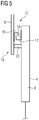
- FIG. 5 shows an embodiment, where a hook-like guide element 15 respectively several of these hook-like guide elements 15 engaging a groove 16 of a guide bar 17 attached at the lower plate 8 of the tower aperture member 4, as shown in fig. 5 .
- This hook engagement is efficient for guiding the door 9 during the horizontal movement.
- a shielding means 18 in form of an elongated shielding plate 19 is attached to the upper plate 4.
- This shielding plate 19 covers the upper guide means 11, as it extends over the roller guide and also a curtain distance over the upper end of the sliding door 9 covering or housing the complete upper guide means 11.
- the lower guide means 12 is covered by a shielding means 18, which is realised by the lower end of the door 9 itself, as, see fig. 5 , it completely extends over the lower guide means 12.
- sealing means are provided for sealing the sliding door 9 in the closed position, when it completely covers the aperture 10.
- the sealing means comprises vertical gaskets 20, 21 as shown in fig. 2 , and horizontal gaskets 22, 23 as shown in fig. 4 and 5 . All gaskets 20, 21, 22, 23 are arranged at the tower aperture member 4, so that the door 9 is moved relative to them and slides over them. At least in the closed position the gaskets 20, 21, 22, 23 completely seal the sliding door 9 to the tower aperture member 4. They build a kind of rectangular sealing frame which completely seals the door 9 along its edges towards the tower aperture member 4, so that a certain air-tight sealing is provided.
- the gasket 20 is shielded by a shieling means 24 provided by the edge 25 of the sliding door 9, which is obviously bent towards the tower aperture member 4. In the closed position this bent edge 25 is adjacent to the gasket 20.
- the gasket 21 on the other side is also protected by a shielding means 24, which is realised by a bar-like limit stop 26, which limits the sliding movement of the door 9 in the closed position according to fig. 2 .
- the edge of the sliding door 9 runs against the limit stops 26, which in this position overlaps the gasket 21 and therefore protects it.
- the shielding means 24 protect the gaskets against dirt and especially sunlight, so that the life term of the gaskets 20, 21 is extended.
- the gaskets 22 and 23 are somehow protected, as they are covered by the sliding door 9 itself, when the door 9 is in the closed position, as shown in fig. 4 and 5 .
- the sliding door 9 extends respectively overlaps with the gaskets 22, 23, as clearly shown, protecting them in the closed position. It needs to be mentioned, that the sliding door 9 is in the closed position most of the time, it is only opened when needed.
- the sliding door arrangement 3 provides access to the inner of the tower 1 through a large aperture, which can be made remarkably larger than apertures in the prior art.
- the door 9 is a sliding door, which hangs on the upper guide means 11 realised by the roller guidance, the door maybe quite large and therefore quite heavy, and may be adapted to cover even very large apertures.
- the integration of the gaskets, which are in this embodiment fixed to the tower aperture member 4, allows for a good and almost air-tight sealing of the door 9 to the tower aperture member 4, and for keeping water out of the tower 1. Due to the shielding means 24 the gaskets 20, 21, 22, 23 are protected against sunlight and dirt, avoiding enhanced wear and prolonging their lifetime. As also the upper and lower guide means 11, 12 are protected by the respective shielding means 18, also the guide means 11, 12 are protected against dirt and wear, only usual maintenance work is necessary.
- the sealed door arrangement 3 provides seawater from entering the inner of the tower 1, which seawater is corrosive and may not enter the inner.
- the movement of the door for opening and closing it is not sensitive to wind pressure, as the door is horizontally moved but not pivoted.
- High wind pressure is especially given at tower respectively turbine installations close to the shore or at off-shore installations, which high wind pressures sometimes do not allow to open or close the door.
Landscapes
- Engineering & Computer Science (AREA)
- Civil Engineering (AREA)
- Structural Engineering (AREA)
- Mechanical Engineering (AREA)
- Chemical & Material Sciences (AREA)
- Life Sciences & Earth Sciences (AREA)
- Architecture (AREA)
- Sustainable Energy (AREA)
- Sustainable Development (AREA)
- Combustion & Propulsion (AREA)
- General Engineering & Computer Science (AREA)
- Materials Engineering (AREA)
- Wood Science & Technology (AREA)
- Specific Sealing Or Ventilating Devices For Doors And Windows (AREA)
Abstract
Description
- The invention refers to a tower of a wind turbine, having a hollow inner space and a door for opening and closing an aperture into the inner space.
- Wind turbines are commonly known. They comprise a tower, on which a nacelle is arranged, comprising a rotatable hub with several blades, which, when the wind blows, make the hub rotate. The hub is coupled to a generator for producing electric energy.
- The tower is usually a hollow, elongated construction based on the ground. Within the tower an inner space is given, in which for example a lift is arranged for transporting persons or goods from the bottom to the nacelle and vice versa.
- For entering the inner of the tower an aperture is provided in the tower, which can be opened and closed by a door. The door is hinged to a door plate, which is attached to a door frame arranged at the tower and firmly fixed to the tower or embedded into the concrete the tower is usually made of. The size of the door itself is restricted to a given maximum size in order to cope with the wind pressure, as, when the wind pressure is high, the door can't be opened or closed, if it is too large. Therefore, when larger components need to be transported into and out of the inner space, it is necessary to dismantle the door and the door plate in order to have a larger aperture. This is cumbersome.
- It is therefore an object of the invention to provide an improved tower.
- For addressing the object the invention proposes a tower of a wind turbine, having a hollow inner space and a door for opening and closing an aperture into the inner space, which tower is characterised in that the door is a sliding door, which is slidingly arranged at a tower aperture member attached to the tower, and which sliding door is at least partially sealed by sealing means to the tower aperture member at least when the door is in the closed position.
- The inventive tower comprises a sliding door, which is slidingly arranged on a tower aperture member, which member comprises a large aperture, which can be opened and closed simply by sliding the door from a closed position to an open position and vice versa. The sliding door is guided on respective guiding means, which allow a safe guidance of the door. The sliding door can have a quite large size, which is remarkably larger than the size of a regular hinged door, as it is sliding and not pivoted like the doors usually installed and which may have only the restricted size. As the sliding door slides, the wind pressure doesn't affect the opening and closing of the door allowing to enlarge the size of the door remarkably. This allows to provide an aperture with a maximum size, which is remarkably larger than the aperture of the door plate of known arrangements of the prior art. Therefore no cumbersome dismantling is necessary, when larger components need to be transported, as the sliding door can be opened to a maximum open position, in which the maximum aperture is available.
- Furthermore a sealing means is provided, which seals the door relative to the tower aperture member, when the door is in the closed position. The sealing means provides at least a partial sealing, preferably a complete sealing of the door relative to the tower aperture member, which complete sealing is advantageous to provide a sufficient air tightness, if requested. Furthermore this sealing also provides protection against water entering the inner of the tower, for example when it rains heavily.
- Beside the fact that the door and the tower aperture member may be flat and rectangular items, so that the sliding door, which is vertically arranged, slides in a horizontal movement, the invention proposes a tower, which has a curved outer surface, wherein the door is a curved door arranged at the curved tower aperture member. The tower aperture member and the door are adapted to the curved form of the tower respectively a tower segment, if the tower is built by several stacked separate segments. In this embodiment the door moves along a circular segmented path between its position, following the overall circular or curved tower surface.
- One central member is the tower aperture member. This member, which is made of metal, like the door, is preferably a rectangular frame member having two side plates, an upper plate and a lower plate, which plates delimit the aperture, whereby the sliding door is slidingly arranged at the upper and the lower member. The tower aperture member, which is preferably a single member for an easy handling, is like a frame, to which the rectangular door is attached. As the door is horizontally movable, it is sidingly arranged respectively guided at the upper and lower plate, where respective upper and lower guide means are arranged for guiding the door at its upper and its lower end. This upper and lower end guidance allows for a safe guidance of the door and for carrying also a heavy weight door, so that the size of the aperture and therefore the door can be remarkably enlarged compared to prior art designs.
- As the upper guide means is concerned, this guide means is preferably realised by a roller guide. The door is preferably guided by rollers on a guide rail arranged at the upper plate. This roller guide provides for a very soft and easy movement. The door hangs via the rollers on the guide rail. In addition to the rollers and the guide rail at the upper plate, the guidance at the lower door and is realised by one or more guide elements engaging a guide bar arranged at the lower plate. These guide elements are preferably hooks engaging a groove provided in the guide bar. This simple hook engagement guide is simple but very effective.
- It needs to be noted that the arrangement may also be vice versa, with the roller guide being provided at the lower door end and the element engaging guidance provided at the upper door end.
- Preferably the upper guide means and/or the lower guide means are shielded by a shielding means extending over it. This is a protection measure in order to cover the respective guide means against dirt and to provide a good lubrication in the sliding or rolling guides.
- In one embodiment the upper shielding means which shields the upper guide mans is a shielding plate arranged at the tower aperture member, which shielding plate extends over the upper end of the door at least when the door is in the closed position. It is sufficient that the shielding plate extends over the upper door end, as the guide means is arranged close to the upper door end, so that it can be safely covered by the shielding plate. The shielding plate has either a longitudinal or a curved form, depending on the overall form of the door arrangement (flat or curved).
- In another embodiment the lower shielding means is preferably provided by the lower end portion of the door, which extends over the lower guide means. Here the door itself provides for a good shielding, as it extends for a certain distance over the lower guide means and covers it.
- As mentioned, a sealing means is provided for at least partially, preferably completely sealing the door relative to the tower aperture member, at least when the door is in the closed position. This avoids an air pressure problem and provides a certain air tightness to a certain extent, and keeps water out of the inner space. Preferably the sealing means is provided in form of respective longitudinal gaskets, which seal the vertical edges and the horizontal edges of the sliding door to the tower aperture member at least when the sliding door is in the closed position. These gaskets are strip-like and may easily be fixed to the respective door arrangement part. They are either fixed to the tower aperture member and seal to the door, which is movable relative to the fixed gaskets and slides over them when it is moved. In an alternative the gaskets may also be fixed to the door and move with the door, they therefore slide along the tower aperture member. Which arrangement ever is taken, the gaskets preferably provide a complete sealing, they therefore build a kind of sealing frame.
- Preferable also at least a part of the sealing means, especially the vertical gaskets, are shielded by a shielding means at least when the sliding door is in the closed position. This shielding provides protection of the gaskets against dirt and sunlight, which improves the lifetime of the gaskets. Especially the vertical gaskets are shielded by respective shielding means, as the horizontal gaskets, which are arranged close to the upper and lower guide means, are covered by the door respectively the guide means shielding.
- One shielding means for shielding a vertical gasket may be provided by an edge of the door itself, which edge is bent towards the tower aperture member, thereby extending over the neighbouring gasket at least in the closed position. So the door edge itself provides the shielding, as it covers the vertical gasket. On the other side another shielding means is provided by a limit stop arranged at the tower aperture member, which stops the closing movement of the door and which extends over the neighbouring gasket when the door is in the closed position. This limit stop has a double function. First it delimits the movement of the door and therefore defines the closed position. Second it provides the gasket shielding or protection. The limit stop is an elongated bar or the like, which covers the neighbouring gasket over its length in the closed position.
- For not only limiting the movement in the closed position, the invention further provides a limit stop which is arranged at the tower aperture member and which stops the opening movement of the sliding door. This limit stop may be a simple bolt or the like, as this limit stop has only the function to limit the movement, but has no shielding function or the like.
- Finally a locking mechanism may be provided for locking the sliding door in the closed position in order to avoid any inadmissible entrance into the inner of the tower. This locking mechanism may be of any kind which provides a safe door lock.
- Furthermore the invention refers to a wind turbine comprising a tower as described above.
- Other objects and features of the present invention will become apparent from the following detailed description considered in conjunction with the accompanying drawings. The drawings, however, are only principle sketches designed solely for the purpose of illustration and do not limit the invention. The drawings show:
- Fig. 1
- shows a principle illustration of an inventive tower,
- Fig. 2
- shows a horizontal cross section of a part of the tower of
fig. 1 , - Fig. 3
- shows a cross section of the door arrangement comprising the tower aperture member and the door,
- Fig. 4
- shows an enlarged view of the section IV in
fig. 3 , and - Fig. 5
- shows an enlarged view of the section V in
fig. 3 . -
Fig. 1 shows a principle illustration of an inventive tower 1 of a wind turbine. The tower, which may be a one-piece tower or which may be built of several segments stacked above each other, comprises a curvedouter surface 2, and adoor arrangement 3. Thedoor arrangement 3 comprises atower aperture member 4 in the form of a rectangular frame member having twoside plates upper plate 7 and alower plate 8, whichtower aperture member 4 is either a one-piece metal member or segmented with separate plates. It is attached to theouter surface 2 of the tower 1 or embedded into the tower itself respectively the material, preferably concrete, the tower is made of. - The
door assembly 3 comprises ametal sliding door 9, which is arranged at thetower aperture member 4. It covers anaperture 10 provided in thetower aperture member 4, whichaperture 10 is delimited by therespective plates aperture 4 is covered by the slidingdoor 9, as shown infig. 2 , which shows the slidingdoor 9 in the closed position, in which it obviously covers theaperture 10 completely. - As
fig. 2 shows, thetower aperture member 4 and the and the slidingdoor 9 are also curved, like the curvedouter surface 2 of the tower 1. They therefore adopt the curvature respectively in form of the tower 1. Furthermorefig. 2 shows alimit stop 27 limiting the opening movement of the slidingdoor 9. - For carrying and guiding the sliding
door 9 at thetower aperture member 4 upper and lower guide means 11, 12 are provided, as depicted infig. 3 and shown in detail infig. 4 and5 . The upper guide means 11 comprises aguide rail 13 fixed to thetower aperture member 4 respectively theupper plate 5. The slidingdoor 9 is provided withseveral rollers 14, which are arranged at the upper end of thedoor 9 and which role on theguide rail 13. Thedoor 9 hangs on theguide rail 13, a very stable attachment is realised, which is adapted to also carry aheavy door 9. - As the
door 9 hangs on the upper guide means 11 respectively theguide rail 13, the lower guide means 12 can be simple.Fig. 5 shows an embodiment, where a hook-like guide element 15 respectively several of these hook-like guide elements 15 engaging agroove 16 of aguide bar 17 attached at thelower plate 8 of thetower aperture member 4, as shown infig. 5 . This hook engagement is efficient for guiding thedoor 9 during the horizontal movement. - Furthermore, a shielding means 18 in form of an
elongated shielding plate 19 is attached to theupper plate 4. This shieldingplate 19 covers the upper guide means 11, as it extends over the roller guide and also a curtain distance over the upper end of the slidingdoor 9 covering or housing the complete upper guide means 11. - Also, the lower guide means 12 is covered by a shielding means 18, which is realised by the lower end of the
door 9 itself, as, seefig. 5 , it completely extends over the lower guide means 12. - Furthermore, sealing means are provided for sealing the sliding
door 9 in the closed position, when it completely covers theaperture 10. The sealing means comprisesvertical gaskets fig. 2 , andhorizontal gaskets fig. 4 and5 . Allgaskets tower aperture member 4, so that thedoor 9 is moved relative to them and slides over them. At least in the closed position thegaskets door 9 to thetower aperture member 4. They build a kind of rectangular sealing frame which completely seals thedoor 9 along its edges towards thetower aperture member 4, so that a certain air-tight sealing is provided. - The
gasket 20 is shielded by a shieling means 24 provided by theedge 25 of the slidingdoor 9, which is obviously bent towards thetower aperture member 4. In the closed position thisbent edge 25 is adjacent to thegasket 20. - The
gasket 21 on the other side is also protected by a shielding means 24, which is realised by a bar-like limit stop 26, which limits the sliding movement of thedoor 9 in the closed position according tofig. 2 . The edge of the slidingdoor 9 runs against the limit stops 26, which in this position overlaps thegasket 21 and therefore protects it. The shielding means 24 protect the gaskets against dirt and especially sunlight, so that the life term of thegaskets - Also, the
gaskets door 9 itself, when thedoor 9 is in the closed position, as shown infig. 4 and5 . The slidingdoor 9 extends respectively overlaps with thegaskets door 9 is in the closed position most of the time, it is only opened when needed. - The sliding
door arrangement 3 according to the invention provides access to the inner of the tower 1 through a large aperture, which can be made remarkably larger than apertures in the prior art. As thedoor 9 is a sliding door, which hangs on the upper guide means 11 realised by the roller guidance, the door maybe quite large and therefore quite heavy, and may be adapted to cover even very large apertures. The integration of the gaskets, which are in this embodiment fixed to thetower aperture member 4, allows for a good and almost air-tight sealing of thedoor 9 to thetower aperture member 4, and for keeping water out of the tower 1. Due to the shielding means 24 thegaskets - Especially when the tower 1 respectively the wind turbine is installed off-shore, the sealed
door arrangement 3 provides seawater from entering the inner of the tower 1, which seawater is corrosive and may not enter the inner. - As the door is a sliding
door 9, the movement of the door for opening and closing it is not sensitive to wind pressure, as the door is horizontally moved but not pivoted. High wind pressure is especially given at tower respectively turbine installations close to the shore or at off-shore installations, which high wind pressures sometimes do not allow to open or close the door. - Although the present invention has been described in detail with reference to the preferred embodiment, the present invention is not limited by the disclosed examples from which the skilled person is able to derive other variations without departing from the scope of the invention.
Claims (15)
- Tower of a wind turbine, having a hollow inner space and a door (9) for opening and closing an aperture into the inner space, characterised in that the door (9) is a sliding door (9), which is slidingly arranged at a tower aperture member (4) attached to the tower, and which sliding door (9) is at least partially sealed by sealing means to the tower aperture member (4) at least when the door is in the closed position.
- Tower according to claim 1, characterised in that the tower has a curved outer surface (2), and that the sliding door (9) is a curved sliding door (9) arranged at the curved tower aperture member (4).
- Tower according to claim 1 or 2, characterised in that the tower aperture member (4) is a rectangular frame member having two side plates (5, 6), an upper plate (7) and a lower plate (8) delimiting the aperture, whereby the sliding door (9) is slidingly arranged at the upper and the lower plate (7, 8) .
- Tower according to one of the preceding claims, characterised in that the sliding door (9) is guided at its upper and its lower end at respective upper and lower guide means (11, 12) arranged at the tower aperture member (4).
- Tower according to claim 4, characterised in that the sliding door (9) is guided by rollers (14) on a guide rail (13) arranged at the upper plate (7) and by one or more guide elements (15) engaging a guide bar (17) arranged at the lower plate (8), or vice versa.
- Tower according to claim 5, characterised in that the guide elements (15) are hooks engaging a groove (16) provided in the guide bar (17).
- Tower according to one of the claims 4 to 6, characterised in that the upper guide means (11) and/or the lower guide means (12) are shielded by a shielding means (18) extending over it.
- Tower according to claim 7, characterised in that the upper shielding means (18) is a shielding plate (19) arranged at the tower aperture member (4), which extends over the upper end of the door (9) at least when the sliding door (9) is in the closed position.
- Tower according to claim 7 or 8, characterised in that the lower shielding means (18) is provided by the lower end portion of the door (9), which extends over the lower guide means (12).
- Tower according to one of the preceding claims, characterised in that a sealing means in form of respective longitudinal gaskets (20, 21, 22, 23) are provided, which seal the vertical edges and the horizontal edges of the sliding door (9) to the tower aperture member (4) at least when the sliding door (9) is in the closed position.
- Tower according to claim 10, characterised in that the gaskets (20, 21, 22, 23) are fixed to the tower aperture member (4) with the sliding door (9) moving relative to them, or that the gaskets (20, 21, 22, 23) are fixed to the sliding door (9) and move with it.
- Tower according to one of the preceding claims, characterised in that at least a part of the sealing means, especially the vertical gaskets (20, 21), are shielded by a shielding means (24) at least when the sliding door (9) is in the closed position.
- Tower according to claim 12, characterised in that one shieling means (24) is provided by an edge (25) of the sliding door (9), which edge (25) is bent towards the tower aperture member (4), thereby extending over the neighbouring gasket (20) at least when the sliding door (9) is in the closed position and that the other shielding means (24) is provided by a limit stop (26) arranged at the tower aperture member (4), which stops the closing movement of the sliding door 9) and which extends over the neighbouring gasket (21) when the sliding door (9) is in the closed position.
- Tower according to one of the preceding claims, characterised in that a limit stop is arranged at the tower aperture member (4), which stops the opening movement of the sliding door (9).
- Wind turbine, comprising a tower (1) according to one of the preceding claims.
Priority Applications (3)
| Application Number | Priority Date | Filing Date | Title |
|---|---|---|---|
| EP20180474.7A EP3926168A1 (en) | 2020-06-17 | 2020-06-17 | Tower of a wind turbine |
| US17/342,958 US11753842B2 (en) | 2020-06-17 | 2021-06-09 | Tower of a wind turbine |
| CN202110672575.8A CN113803214A (en) | 2020-06-17 | 2021-06-17 | Tower of a wind turbine |
Applications Claiming Priority (1)
| Application Number | Priority Date | Filing Date | Title |
|---|---|---|---|
| EP20180474.7A EP3926168A1 (en) | 2020-06-17 | 2020-06-17 | Tower of a wind turbine |
Publications (1)
| Publication Number | Publication Date |
|---|---|
| EP3926168A1 true EP3926168A1 (en) | 2021-12-22 |
Family
ID=71105357
Family Applications (1)
| Application Number | Title | Priority Date | Filing Date |
|---|---|---|---|
| EP20180474.7A Withdrawn EP3926168A1 (en) | 2020-06-17 | 2020-06-17 | Tower of a wind turbine |
Country Status (3)
| Country | Link |
|---|---|
| US (1) | US11753842B2 (en) |
| EP (1) | EP3926168A1 (en) |
| CN (1) | CN113803214A (en) |
Families Citing this family (3)
| Publication number | Priority date | Publication date | Assignee | Title |
|---|---|---|---|---|
| EP3926168A1 (en) * | 2020-06-17 | 2021-12-22 | Siemens Gamesa Renewable Energy A/S | Tower of a wind turbine |
| EP4212723B1 (en) * | 2022-01-14 | 2025-03-12 | Siemens Gamesa Renewable Energy A/S | Safety door assembly |
| EP4215744B1 (en) * | 2022-01-20 | 2025-07-23 | Siemens Gamesa Renewable Energy Innovation & Technology S.L. | Door arrangement for a wind turbine, door locking device and wind turbine |
Citations (7)
| Publication number | Priority date | Publication date | Assignee | Title |
|---|---|---|---|---|
| US1112203A (en) * | 1913-04-01 | 1914-09-29 | Albert J Fandrey | Atmospheric power-generator. |
| EP1152114A1 (en) * | 2000-05-05 | 2001-11-07 | Kason Industries, Inc. | Suspension system for sliding door |
| KR20100040086A (en) * | 2008-10-09 | 2010-04-19 | (주)삼성판넬플랜트 | Auto and manual door sliding rail structure |
| CN206290376U (en) * | 2016-12-19 | 2017-06-30 | 北京金风科创风电设备有限公司 | The platform structure of tower, tower and wind power generating set |
| CN206309530U (en) * | 2016-12-27 | 2017-07-07 | 北京金风科创风电设备有限公司 | Tower workbench |
| WO2019096360A1 (en) * | 2017-11-20 | 2019-05-23 | Envision Energy (Denmark) Aps | Nacelle, wind turbine, wind turbine air filtration system and a method for filtration of air in the nacelle of a wind turbine |
| KR101994486B1 (en) * | 2012-08-22 | 2019-09-30 | 두산중공업 주식회사 | A double slide gate equipped the tower hall of the wind generator tower and wind generator including the same |
Family Cites Families (5)
| Publication number | Priority date | Publication date | Assignee | Title |
|---|---|---|---|---|
| US6330763B1 (en) * | 1999-09-10 | 2001-12-18 | Rite-Hite Holding Corporation | Translating door with disengageable seals |
| US20060032161A1 (en) * | 2004-07-24 | 2006-02-16 | Rytec Corporation | Door assembly and method of making same |
| US10837221B2 (en) * | 2017-07-18 | 2020-11-17 | Shmulik Cohen | Thermally-efficient slidable fenestration assembly |
| JP7107488B2 (en) * | 2020-01-23 | 2022-07-27 | シーエス テック カンパニー、リミテッド | Window assembly with ventilation function and horizontal tightness function |
| EP3926168A1 (en) * | 2020-06-17 | 2021-12-22 | Siemens Gamesa Renewable Energy A/S | Tower of a wind turbine |
-
2020
- 2020-06-17 EP EP20180474.7A patent/EP3926168A1/en not_active Withdrawn
-
2021
- 2021-06-09 US US17/342,958 patent/US11753842B2/en active Active
- 2021-06-17 CN CN202110672575.8A patent/CN113803214A/en active Pending
Patent Citations (7)
| Publication number | Priority date | Publication date | Assignee | Title |
|---|---|---|---|---|
| US1112203A (en) * | 1913-04-01 | 1914-09-29 | Albert J Fandrey | Atmospheric power-generator. |
| EP1152114A1 (en) * | 2000-05-05 | 2001-11-07 | Kason Industries, Inc. | Suspension system for sliding door |
| KR20100040086A (en) * | 2008-10-09 | 2010-04-19 | (주)삼성판넬플랜트 | Auto and manual door sliding rail structure |
| KR101994486B1 (en) * | 2012-08-22 | 2019-09-30 | 두산중공업 주식회사 | A double slide gate equipped the tower hall of the wind generator tower and wind generator including the same |
| CN206290376U (en) * | 2016-12-19 | 2017-06-30 | 北京金风科创风电设备有限公司 | The platform structure of tower, tower and wind power generating set |
| CN206309530U (en) * | 2016-12-27 | 2017-07-07 | 北京金风科创风电设备有限公司 | Tower workbench |
| WO2019096360A1 (en) * | 2017-11-20 | 2019-05-23 | Envision Energy (Denmark) Aps | Nacelle, wind turbine, wind turbine air filtration system and a method for filtration of air in the nacelle of a wind turbine |
Also Published As
| Publication number | Publication date |
|---|---|
| US20210396032A1 (en) | 2021-12-23 |
| US11753842B2 (en) | 2023-09-12 |
| CN113803214A (en) | 2021-12-17 |
Similar Documents
| Publication | Publication Date | Title |
|---|---|---|
| US11753842B2 (en) | Tower of a wind turbine | |
| RU2472911C2 (en) | Device with curtain and element for reinstallation of curtain into guide | |
| US5657805A (en) | Wind-resistant overhead closure | |
| WO2001048349A1 (en) | Wind-resistant coiling door | |
| US11536086B2 (en) | Base slat pry stopper | |
| KR102233701B1 (en) | Hatch cover switchgear | |
| US6068040A (en) | Slat edge retainer for overhead rolling doors | |
| US5183093A (en) | Removable sealing device for a raisable-curtain industrial door | |
| EP2607600B1 (en) | Apparatus for flood-proofing a garage with a single panel garage door | |
| US6508292B1 (en) | Retractable mosquito net | |
| DK165515B (en) | Device in sliding doors | |
| CN102124179A (en) | Vertical lift door | |
| JP2015074940A (en) | Gate device for preventing flood damage of parking apparatus | |
| EP2014866B1 (en) | Double-curtain rapid-opening door | |
| EP3559458A1 (en) | A nacelle for a wind turbine and a wind turbine | |
| AU2011204983A1 (en) | Window assembly | |
| EP3259429A1 (en) | Mutual coupling system between the slats for the semi-aperture of a roller shutter by means of sliding | |
| US20180051452A1 (en) | Mechanical Closure Device | |
| CN210659862U (en) | Opening and closing mechanism of accumulation door | |
| CN207349477U (en) | The gate valve of easy access | |
| NZ726011A (en) | Overhead door highwind retention system | |
| CN114846562B (en) | Containment system | |
| US10934674B2 (en) | Single bay mechanical closure device | |
| KR100820989B1 (en) | Fire door moving frame system | |
| CN222477375U (en) | Novel drainage device for reservoir |
Legal Events
| Date | Code | Title | Description |
|---|---|---|---|
| PUAI | Public reference made under article 153(3) epc to a published international application that has entered the european phase |
Free format text: ORIGINAL CODE: 0009012 |
|
| STAA | Information on the status of an ep patent application or granted ep patent |
Free format text: STATUS: THE APPLICATION HAS BEEN PUBLISHED |
|
| AK | Designated contracting states |
Kind code of ref document: A1 Designated state(s): AL AT BE BG CH CY CZ DE DK EE ES FI FR GB GR HR HU IE IS IT LI LT LU LV MC MK MT NL NO PL PT RO RS SE SI SK SM TR |
|
| B565 | Issuance of search results under rule 164(2) epc |
Effective date: 20201113 |
|
| STAA | Information on the status of an ep patent application or granted ep patent |
Free format text: STATUS: REQUEST FOR EXAMINATION WAS MADE |
|
| 17P | Request for examination filed |
Effective date: 20220622 |
|
| RBV | Designated contracting states (corrected) |
Designated state(s): AL AT BE BG CH CY CZ DE DK EE ES FI FR GB GR HR HU IE IS IT LI LT LU LV MC MK MT NL NO PL PT RO RS SE SI SK SM TR |
|
| STAA | Information on the status of an ep patent application or granted ep patent |
Free format text: STATUS: THE APPLICATION IS DEEMED TO BE WITHDRAWN |
|
| 18D | Application deemed to be withdrawn |
Effective date: 20250103 |