EP3926104A1 - Vacuum excavator tank and door system - Google Patents
Vacuum excavator tank and door system Download PDFInfo
- Publication number
- EP3926104A1 EP3926104A1 EP21179220.5A EP21179220A EP3926104A1 EP 3926104 A1 EP3926104 A1 EP 3926104A1 EP 21179220 A EP21179220 A EP 21179220A EP 3926104 A1 EP3926104 A1 EP 3926104A1
- Authority
- EP
- European Patent Office
- Prior art keywords
- linkage arm
- door
- arm
- tank
- linkage
- Prior art date
- Legal status (The legal status is an assumption and is not a legal conclusion. Google has not performed a legal analysis and makes no representation as to the accuracy of the status listed.)
- Granted
Links
Images




Classifications
-
- E—FIXED CONSTRUCTIONS
- E02—HYDRAULIC ENGINEERING; FOUNDATIONS; SOIL SHIFTING
- E02F—DREDGING; SOIL-SHIFTING
- E02F3/00—Dredgers; Soil-shifting machines
- E02F3/04—Dredgers; Soil-shifting machines mechanically-driven
- E02F3/88—Dredgers; Soil-shifting machines mechanically-driven with arrangements acting by a sucking or forcing effect, e.g. suction dredgers
- E02F3/8891—Dredgers; Soil-shifting machines mechanically-driven with arrangements acting by a sucking or forcing effect, e.g. suction dredgers wherein at least a part of the soil-shifting equipment is handheld
-
- B—PERFORMING OPERATIONS; TRANSPORTING
- B60—VEHICLES IN GENERAL
- B60P—VEHICLES ADAPTED FOR LOAD TRANSPORTATION OR TO TRANSPORT, TO CARRY, OR TO COMPRISE SPECIAL LOADS OR OBJECTS
- B60P3/00—Vehicles adapted to transport, to carry or to comprise special loads or objects
- B60P3/22—Tank vehicles
- B60P3/224—Tank vehicles comprising auxiliary devices, e.g. for unloading or level indicating
- B60P3/2245—Adaptations for loading or unloading
-
- B—PERFORMING OPERATIONS; TRANSPORTING
- B60—VEHICLES IN GENERAL
- B60P—VEHICLES ADAPTED FOR LOAD TRANSPORTATION OR TO TRANSPORT, TO CARRY, OR TO COMPRISE SPECIAL LOADS OR OBJECTS
- B60P3/00—Vehicles adapted to transport, to carry or to comprise special loads or objects
- B60P3/22—Tank vehicles
- B60P3/224—Tank vehicles comprising auxiliary devices, e.g. for unloading or level indicating
- B60P3/226—Arrangements of access openings or covers therefor
-
- E—FIXED CONSTRUCTIONS
- E02—HYDRAULIC ENGINEERING; FOUNDATIONS; SOIL SHIFTING
- E02F—DREDGING; SOIL-SHIFTING
- E02F3/00—Dredgers; Soil-shifting machines
- E02F3/04—Dredgers; Soil-shifting machines mechanically-driven
- E02F3/88—Dredgers; Soil-shifting machines mechanically-driven with arrangements acting by a sucking or forcing effect, e.g. suction dredgers
- E02F3/90—Component parts, e.g. arrangement or adaptation of pumps
-
- E—FIXED CONSTRUCTIONS
- E05—LOCKS; KEYS; WINDOW OR DOOR FITTINGS; SAFES
- E05F—DEVICES FOR MOVING WINGS INTO OPEN OR CLOSED POSITION; CHECKS FOR WINGS; WING FITTINGS NOT OTHERWISE PROVIDED FOR, CONCERNED WITH THE FUNCTIONING OF THE WING
- E05F15/00—Power-operated mechanisms for wings
- E05F15/50—Power-operated mechanisms for wings using fluid-pressure actuators
- E05F15/53—Power-operated mechanisms for wings using fluid-pressure actuators for swinging wings
-
- F—MECHANICAL ENGINEERING; LIGHTING; HEATING; WEAPONS; BLASTING
- F16—ENGINEERING ELEMENTS AND UNITS; GENERAL MEASURES FOR PRODUCING AND MAINTAINING EFFECTIVE FUNCTIONING OF MACHINES OR INSTALLATIONS; THERMAL INSULATION IN GENERAL
- F16J—PISTONS; CYLINDERS; SEALINGS
- F16J13/00—Covers or similar closure members for pressure vessels in general
- F16J13/16—Pivoted closures
- F16J13/18—Pivoted closures pivoted directly on the frame
-
- E—FIXED CONSTRUCTIONS
- E02—HYDRAULIC ENGINEERING; FOUNDATIONS; SOIL SHIFTING
- E02F—DREDGING; SOIL-SHIFTING
- E02F3/00—Dredgers; Soil-shifting machines
- E02F3/04—Dredgers; Soil-shifting machines mechanically-driven
- E02F3/88—Dredgers; Soil-shifting machines mechanically-driven with arrangements acting by a sucking or forcing effect, e.g. suction dredgers
- E02F3/8816—Mobile land installations
-
- E—FIXED CONSTRUCTIONS
- E05—LOCKS; KEYS; WINDOW OR DOOR FITTINGS; SAFES
- E05Y—INDEXING SCHEME ASSOCIATED WITH SUBCLASSES E05D AND E05F, RELATING TO CONSTRUCTION ELEMENTS, ELECTRIC CONTROL, POWER SUPPLY, POWER SIGNAL OR TRANSMISSION, USER INTERFACES, MOUNTING OR COUPLING, DETAILS, ACCESSORIES, AUXILIARY OPERATIONS NOT OTHERWISE PROVIDED FOR, APPLICATION THEREOF
- E05Y2201/00—Constructional elements; Accessories therefor
- E05Y2201/60—Suspension or transmission members; Accessories therefor
- E05Y2201/604—Transmission members
-
- E—FIXED CONSTRUCTIONS
- E05—LOCKS; KEYS; WINDOW OR DOOR FITTINGS; SAFES
- E05Y—INDEXING SCHEME ASSOCIATED WITH SUBCLASSES E05D AND E05F, RELATING TO CONSTRUCTION ELEMENTS, ELECTRIC CONTROL, POWER SUPPLY, POWER SIGNAL OR TRANSMISSION, USER INTERFACES, MOUNTING OR COUPLING, DETAILS, ACCESSORIES, AUXILIARY OPERATIONS NOT OTHERWISE PROVIDED FOR, APPLICATION THEREOF
- E05Y2900/00—Application of doors, windows, wings or fittings thereof
- E05Y2900/50—Application of doors, windows, wings or fittings thereof for vehicles
- E05Y2900/518—Application of doors, windows, wings or fittings thereof for vehicles for working vehicles
-
- E—FIXED CONSTRUCTIONS
- E05—LOCKS; KEYS; WINDOW OR DOOR FITTINGS; SAFES
- E05Y—INDEXING SCHEME ASSOCIATED WITH SUBCLASSES E05D AND E05F, RELATING TO CONSTRUCTION ELEMENTS, ELECTRIC CONTROL, POWER SUPPLY, POWER SIGNAL OR TRANSMISSION, USER INTERFACES, MOUNTING OR COUPLING, DETAILS, ACCESSORIES, AUXILIARY OPERATIONS NOT OTHERWISE PROVIDED FOR, APPLICATION THEREOF
- E05Y2900/00—Application of doors, windows, wings or fittings thereof
- E05Y2900/50—Application of doors, windows, wings or fittings thereof for vehicles
- E05Y2900/53—Type of wing
-
- E—FIXED CONSTRUCTIONS
- E05—LOCKS; KEYS; WINDOW OR DOOR FITTINGS; SAFES
- E05Y—INDEXING SCHEME ASSOCIATED WITH SUBCLASSES E05D AND E05F, RELATING TO CONSTRUCTION ELEMENTS, ELECTRIC CONTROL, POWER SUPPLY, POWER SIGNAL OR TRANSMISSION, USER INTERFACES, MOUNTING OR COUPLING, DETAILS, ACCESSORIES, AUXILIARY OPERATIONS NOT OTHERWISE PROVIDED FOR, APPLICATION THEREOF
- E05Y2900/00—Application of doors, windows, wings or fittings thereof
- E05Y2900/50—Application of doors, windows, wings or fittings thereof for vehicles
- E05Y2900/53—Type of wing
- E05Y2900/546—Tailboards, tailgates or sideboards opening upwards
-
- E—FIXED CONSTRUCTIONS
- E05—LOCKS; KEYS; WINDOW OR DOOR FITTINGS; SAFES
- E05Y—INDEXING SCHEME ASSOCIATED WITH SUBCLASSES E05D AND E05F, RELATING TO CONSTRUCTION ELEMENTS, ELECTRIC CONTROL, POWER SUPPLY, POWER SIGNAL OR TRANSMISSION, USER INTERFACES, MOUNTING OR COUPLING, DETAILS, ACCESSORIES, AUXILIARY OPERATIONS NOT OTHERWISE PROVIDED FOR, APPLICATION THEREOF
- E05Y2999/00—Subject-matter not otherwise provided for in this subclass
Definitions
- the present disclosure relates generally to a vacuum excavator system for removing soil to expose underground utilities (such as electrical and cable services, water and sewage services, etc.), and more particularly to an improved vacuum tank and door system for use with such system.
- underground utilities such as electrical and cable services, water and sewage services, etc.
- One design uses high pressure air delivered through a tool to loosen soil and a vacuum system to vacuum away dirt after it is loosened to form a hole.
- Another system uses high pressure water delivered by a tool to soften the soil and create a soil/water slurry mixture. The tool is connected with a vacuum system for vacuuming the slurry away into a collection tank. The tank may then be emptied by opening a door on the tank.
- An embodiment of the present disclosure provides a collection tank for a mobile vacuum excavator, including a generally cylindrical body having a front with a closed end, a rear with an open end having a periphery, a door having a periphery that abuts the periphery of the open end when the door is closed over the open end, and a linkage assembly having a first end attached to the door so that the first end moves with movement of the door and a second end attached to the body of the collection tank.
- the linkage assembly includes a first arm, a second arm pivotally attached to the first arm so that a first pivotal movement of the first arm and the second arm with respect to each other drives the first end and the second end away from each other and so that a second pivotal movement of the first arm and the second arm with respect to each other moves the first end and the second end toward each other.
- An actuator is attached to the first arm and to the second arm so that the actuator moves with movement of the first arm and with movement of the second arm and so that actuation of the actuator in a first direction moves the first arm and the second arm in the first pivotal movement and so that actuation of the actuator in a second direction moves the first arm and the second arm in the second pivotal movement.
- a collection tank for a mobile vacuum excavator includes a generally cylindrical body including a front with a closed end, a rear with an open end having a periphery, a door having a periphery that abuts the periphery of the open end when the door is closed over the open end, and a linkage assembly having a first arm pivotally attached to the body at a mounting end about a mount axis, a second arm pivotally attached to the door at a mounting end about a door closure axis, so that the mounting end moves with movement of the door, and pivotally attached to the first arm at a door latch axis.
- a first pivotal movement of the first arm and the second arm with respect to each other drives the mounting end of the first arm and the mounting end of the second arm away from each other and a second pivotal movement of the first arm and the second arm with respect to each other drives the mounting end of the first arm and the mounting end of the second end toward each other, wherein the second arm has a distal end and wherein a door latch plane is defined by the mount axis and the door closure axis.
- a powered cylinder actuator is attached to the first arm and to the second arm so that the actuator moves with movement of the first arm and with movement of the second arm and so that retraction of the actuator moves the first arm and the second arm in the first pivotal movement and so that extension of the actuator in a second direction moves the first arm and the second arm in the second pivotal movement, wherein the door latch axis is on one side of the door latch plane when the actuator is in a retracted state and the door latch axis is on an opposite side of the door latch plane when the actuator is in an extended state.
- a collection tank for a mobile vacuum excavator has a generally cylindrical body having a front with a closed end, and a rear with an open end having a periphery.
- a door has a periphery that abuts the periphery of the open end when the door is closed over the open end.
- a linkage assembly has a first end attached to the door and a second end attached to the body.
- the linkage assembly comprises a first arm, a second arm pivotally attached to the first arm so that a first pivotal movement of the first arm and the second arm with respect to each other drives the first end and the second end away from each other and so that a second pivotal movement of the first arm and the second arm with respect to each other moves the first end and the second end toward each other, and a linear actuator attached at a first operative end of the linear actuator to one of the first arm and the second arm, so that the first operative end of the linear actuator moves with movement of the one of the first arm and the second arm, and at a second operative end of the linear actuator to the body proximate the second end of the linkage assembly so that actuation of the linear actuator in a first direction moves the first arm and the second arm in the first pivotal movement and so that actuation of the actuator in a second direction moves the first arm and the second arm in the second pivotal movement.
- a collection tank for a mobile vacuum excavator has a generally cylindrical body having a front with a closed end, and a rear with an open end having a periphery.
- a door has a periphery that abuts the periphery of the open end when the door is closed over the open end.
- a linkage assembly has a first end attached to the door so that the first end moves with movement of the door and a second end attached to the body.
- the linkage assembly has a first arm, a second arm pivotally attached to the first arm so that a first pivotal movement of the first arm and the second arm with respect to each other drives the first end and the second end away from each other and so that a second pivotal movement of the first arm and the second arm with respect to each other moves the first end and the second end toward each other, and a linear actuator.
- the linear actuator is attached at a first operative end of the linear actuator to one of the first arm and the second arm so that the first operative end of the linear actuator is movable about a first axis during the first pivotal movement and the second pivotal movement and at a second operative end of the linear actuator to the body so that the second operative end of the linear actuator is movable about a second axis during the first pivotal movement and the second pivotal movement, and so that actuation of the linear actuator in a first direction moves the first arm and the second arm in the first pivotal movement and so that actuation of the linear actuator in a second direction moves the first arm and the second arm in the second pivotal movement.
- the linear actuator is attached to the one of the first arm and the second arm and to the body so that, when the door is closed over the open end, the second axis is between the open end and the first axis.
- a collection tank for a mobile excavator has a generally cylindrical body with a tank centerline, a front with a closed end, and a rear with an open end having a sealing flange that defines a first plane perpendicular to the tank centerline.
- a door is pivotally connected to the generally cylindrical body and has a periphery that abuts the sealing flange of the open end when the door is closed over the open end.
- a first linkage arm has an end pivotally connected to the body.
- a second linkage arm has a first end pivotally connected to the door and a second end.
- An actuator has a first end that is pivotally connected to one of the first linkage arm or the second linkage arm at a first pivot point lying in a third plane that is perpendicular to the tank centerline, and a second end having a second pivot point located between the first plane and the third plane.
- the first pivot point and the second pivot point lie in a plane that is parallel to or generally parallel to the tank centerline.
- orientation e.g. "forward,” “rearward,” “upper,” “lower,” “horizontal,” “vertical,” and similar terms as used herein are intended to refer to relative orientation of components of the devices described herein with respect to each other under an assumption of a consistent point of reference but do not require any specific orientation of the overall system.
- the discussion herein may refer to a "forward" or "front” end of an earth excavation system or a generally cylindrical collection tank used therewith, referring to a direction toward the end of the earth excavator that has a motorized cab or that is configured in a trailer configuration to be attached to a vehicle rear end, or a "rearward” end of the earth excavation system or tank, referring to a direction toward the system's rear, at which the tank door is disposed and opens and closes against the open end of the tank.
- the present discussion may also refer to "upper” and/or “lower” surfaces of the earth excavation system and/or its components, generally with regard to the orientation of the system as shown in Figures 1 and 2 .
- either of the terms “or” and “one of_ and _,” as used in this disclosure and the appended claims, is intended to mean an inclusive “or” rather than an exclusive “or.” That is, unless specified otherwise, or clear from the context, either of the phrases “X employs A or B” and “X employs one of A and B” is intended to mean any of the natural inclusive permutations. That is, either phrase is satisfied by any of the following instances: X employs A; X employs B; or X employs both A and B, and this is true of similar phrases, such as "at least one of A or B" or "at least one of A and B,” that may be utilized in the specification or claims.
- An attachment may refer to a direct or an indirect connection between two or more things, and "attach,” with respect to two or more components A and B, may refer to fastening/joining A and B to each other directly, so that they physically touch each other, or indirectly, so that they are joined to each other through one or more other components.
- an earth excavator system 10 generally includes a water reservoir tank (in this embodiment, a pair of tanks) 12, a collection tank 14, a motor 16 (which, in the illustrated embodiment may be the vehicle engine, delivering power through, e.g., a mechanical, hydraulic, or electric transmission system, but which may also be, e.g., a dedicated motor mounted on the chassis aft of the vehicle cab), and an earth removal system 18, all mounted on a mobile chassis 24 that supports the various components.
- excavator system 10 includes chassis 24 of a motor vehicle 20 (which may also be considered part of the excavator system).
- Apparatus 10 includes a front 11, a rear 13, and a longitudinal axis 129 that extends through front 11 and rear 13.
- the vacuum excavator system 10 includes a wand 4 ( Fig. 3B ) for directing pressurized water W toward earthen material to cut the earthen material.
- Wand 4 is connected to an excavation fluid pump 6 that supplies water to wand 4 via a high-pressure water hose 70.
- Pump 6 may supply a pressure of, for example, at least about 500 psi or at least about 1,000 psi (e.g., from about 1,000 psi to about 5,000 psi or from 1,000 psi to about 3,000 psi).
- wand 4 includes a rotary nozzle 8 ( Fig. 3B ) for directing water W toward the earthen material to cut the earthen material.
- a rotary nozzle 8 for directing water W toward the earthen material to cut the earthen material.
- any rotary nozzle that causes the water to be directed toward the earthen material in a circular path at the site of the excavation may be used.
- Such rotary nozzles may include a rotor insert with blades that rotate around a longitudinal axis of the nozzle when water is forced through the nozzle.
- the rotor insert may include three or more channels that force fluid to flow in different pathways through the rotor insert to cause the water to move along a circular path as it contacts the excavation material (i.e., the water moves within a cone that extends from the nozzle toward the excavated material).
- a straight tip nozzle that directs fluid along a straight path in a concentrated jet may be used.
- High-pressure water hose 70 is connected, via a valve, to fluid pump 6 to provide water to the earth removal system as selected by the user.
- a distal end of wand 4 is pressed downwardly into the ground.
- wand 4 is moved in a generally circular manner as it is pressed downward, thereby removing material from a large cross-section area. Slurry formed in the hole is vacuumed through hose 5 and accumulates in collection tank 14. Once the excavation is completed and the utility is exposed, the vacuum system can be shut down, and the operators may examine or repair the utility as needed.
- Vacuum excavation system 10 includes a vacuum system 7 ( Fig. 2A ) for removing spoil material from the excavation site.
- Spoil material or simply “spoils” may include, without limitation, rocks, cut earthen material (e.g., small particulate such as sand to larger pieces of earth that are cut loose by the jet of high pressure water), slurry, and water used for excavation.
- the spoil material may have a consistency similar to water, a slurry, or even solid earth, organic material, or rocks.
- the terms used herein for materials that may be processed by the vacuum excavation system such as, for example, “spoils,” “spoil material,” “cut earthen material” and “water,” should not be considered in a limiting sense unless stated otherwise.
- Vacuum system 7 includes a vacuum pump system 33 and a boom 9 that is capable of rotating toward the excavation site to remove material from the excavation site.
- Boom 9 may include a flexible portion, such as a hose, 5 ( Figs. 1 and 3A ) that extends downward to the ground to vacuum spoil material from the excavation site.
- Flexible portion 5 may be manipulated by a user to direct the vacuum suction toward the excavation site.
- Vacuum system 7 acts to entrain the cut earth and the water used to excavate the site in a stream of air.
- a blower or vacuum pump 31 ( Fig. 3A ) pulls a vacuum through boom 9 to entrain the material in the airstream. Air is discharged from the blower 31 after material is removed from the airstream.
- the airstream having water and cut earth entrained therein is pulled through boom 9 and through a series of conduits and is pulled into collection tank 14.
- the collection tank 14 removes at least a portion of cut earthen material and water from the airstream.
- Air exits one or more collection tank air outlets 27 through one or more conduits 25 and is introduced into cyclones 11 ( Figs. 1 and 3A ) via conduit 25 to remove additional spoil material (e.g., water, small solids such as sand, low density particles such as sticks and grass, and the like) not separated in the collection tank.
- additional spoil material e.g., water, small solids such as sand, low density particles such as sticks and grass, and the like
- a cyclone discharge pump e.g., peristaltic pump
- the air removed from cyclones 11 is introduced into one or more filter elements before entering vacuum pump 31.
- Vacuum pump 31 may be disposed in or near the engine compartment. Air is removed from the apparatus through a vacuum exhaust 29.
- Vacuum pump 31 generates vacuum in the system to pull water and cut earthen material into system 10 for processing.
- vacuum pump 31 is a positive displacement pump.
- Such positive displacement pumps may include dual-lobe or tri-lobe impellers (e.g., a screw rotor) that draw air into a vacuum side of the pump and forces air out the pressure side.
- the pump may be powered by a motor having a power output of, for example, at least 75 hp, at least 100 hp or even at least 125 hp.
- collection tank 14 has a generally cylindrical body 15 having a closed front end 17 ( Figures 2B and 2C ) and open rear end 19 ( Figure 8 ).
- a discharge door 126 is connected to the open rear end 19 of the tank body 15 by a hinge 128 that allows the door 126 to swing open, thereby providing access to the tank's interior for cleaning.
- a pair of hydraulic cylinders may be provided for tilting the forward end of tank 14 upwards in order to cause the contents to run towards discharge door 126.
- a gate valve 140 coupled to a drain 142 in discharge door 126, drains the liquid portion of the slurry in tank 14 without requiring the door to be opened. Gate valve 140 may also be used to introduce air into collection tank 14 to reduce the vacuum in the tank so that the door 126 may be more easily opened.
- a nozzle tube that includes nozzles for directing high pressure water about the interior of the tank, and particularly towards the base of the tank.
- the nozzles are actuated by opening a valve connected to a water pump (e.g. water pump 6), which delivers high pressure water from the pump to the nozzles for producing a vigorous cleaning action in the tank.
- a water pump e.g. water pump 6
- a small amount of water is allowed to continuously drip through the nozzles to pressurize them so as to prevent dirt and slurry from entering and clogging the nozzles.
- the hydraulic cylinders, used to tilt collection tank 14, may be powered, e.g., by an electric hydraulic pump (not shown) provided for the purpose, by the power source (engine) of the truck, or by the independent power source for the vacuum.
- the hydraulic pump connects to a hydraulic reservoir and is driven by the electrical system provided from the motor.
- a high-pressure output line and a return line connect the hydraulic pump to the hydraulic cylinders.
- Earth excavator system 10 can be used to dig multiple holes before having to empty collection tank 14. However, once collection tank 14 is full, it can be emptied at an appropriate dump site. When ready to open discharge door 126, vacuum pump 31 is shut down, and the vacuum pressure is released so that air enters the tank, thereby allowing the internal pressure of the tank to match the ambient atmospheric pressure and allowing the door to be opened. Once the door is opened, the hydraulic cylinders can be activated to raise forward end 17 ( Figure 2 ) upward, dumping the slurry from the tank.
- tank 14 is pivotally attached to chassis 24 ( Figures 1 and 2 ) at a pair of hinges 90A and 90B that include relatively pivotable portions that pivot about an axis 88 ( Figure 4 ) transverse to axis 129 to allow tank 14 to pivot about axis 88 as the hydraulic cylinders move the tank's forward end up and down, and such that when the hydraulic cylinders push the tank's forward end upward, liquid and solid matter retained in collection tank 14 may be discharged through the tank's open end.
- hinges 90A and 90B that include relatively pivotable portions that pivot about an axis 88 ( Figure 4 ) transverse to axis 129 to allow tank 14 to pivot about axis 88 as the hydraulic cylinders move the tank's forward end up and down, and such that when the hydraulic cylinders push the tank's forward end upward, liquid and solid matter retained in collection tank 14 may be discharged through the tank's open end.
- collection tank 14 is equipped with a sealing flange 74 that defines a perimeter about the tank body's open end 19 ( Figure 8 ), discharge door 126 that is pivotally connected to the tank body by a pair of slotted hinges 128, and a discharge door latching system 80.
- Hinges 128 are slotted hinges, thereby allowing the portions of the hinges on the door to move slightly back and forth on the hinge pins in the direction of axis 129 as door 126 pivots to and away from the tank opening.
- hinges 128 allow the door's slight movement to allow the door's edge to clear the tank open edge.
- hinges 128 allow the door to move back in the other direction so that the door seats evenly against the tank open end periphery.
- Discharge door latching system 80 has two linkage assemblies 100A and 100B, each including an upper linkage arm 102, a lower linkage arm 104, and an actuator (in the illustrated embodiment, a linear actuator, e.g. a hydraulic cylinder).
- linkage assembly 100A where all reference numbers are annotated with a capital "A.”
- linkage assembly 100B as a mirror image of linkage assembly 100A.
- a linear actuator is an actuator that creates motion in a straight line, which may be referred to as the actuation dimension.
- linear actuators include, but are not limited to, mechanical actuators (such as screws, rack and pinion devices, belt drives, hydraulic cylinders, and pneumatic actuators), electro-mechanical actuators, and linear motors.
- mechanical actuators such as screws, rack and pinion devices, belt drives, hydraulic cylinders, and pneumatic actuators
- electro-mechanical actuators electro-mechanical actuators
- linear motors linear motors.
- hydraulic cylinders are used in the examples described herein, it should be understood that this is for purposes of example only and that other linear and nonlinear actuators may be used to drive one or more linkage assemblies as discussed herein.
- a lower linkage arm 104A is rigidly connected to a linkage assembly pivot bar 110 ( Figure 8 ) at the pivot bar's first end 110A so that the lower linkage arm and the pivot bar rotate together.
- lower linkage arm 104A is connected to pivot bar 110 at a portion of lower linkage arm 104A that is disposed between a first end 105A and a second end 107A of the lower linkage arm.
- Pivot bar 110 extends from its first end 110A, through the outer wall of collection tank body 15 ( Figures 2 and 4 ), and into a pivot bar/support tube 115 ( Figure 8 ) that passes through an internal chamber 111 ( Figure 8 ) of tank 14.
- the pivot bar is pivotable about an axis 113 oriented generally parallel to an inner diameter of internal chamber 111 ( Figure 8 ) of collection tank 14.
- the pivot bar extends along its axis 113 (which is also the pivot bar's elongation dimension) through tank internal chamber 111 and further extends through the opposite side of the collection tank outer wall and terminates at a second end of the pivot bar 110.
- pivot bar 110 extends through the tank internal chamber 111, without a support tube 115 (which may be sealingly attached to through holes through the tank wall to receive the bar), a sealed bearing (not shown) may rotatably engage pivot bar 110 at the point where the pivot bar 110 passes through the collection tank external wall to ensure that tank internal chamber 111 ( Figure 8 ) remains sealed from the outside atmosphere.
- pivot bar/support tube 115 spans interior 111 of tank 14 and provides structural support to the walls of the tank 14.
- both the pivot bar 110 and the support tube 115 may be provided, though not necessarily one within the other as in the embodiments illustrated herein.
- pivot bar 110 may be omitted, though the tubing through which it passes may be retained, e.g., for structural support.
- each of the two lower linkage arms may be pivotally attached to the tank wall, e.g. about a pin welded or bolted to the tank wall or received within a receiver manufactured into the tank wall.
- First end 105A of first lower linkage arm 104A has an actuating cylinder mounting hole (not shown) adjacent its distal end.
- actuating cylinder 160A is a hydraulic cylinder having a cylinder housing 162A and a piston rod 164A that is slidably received in housing 162A.
- Piston rod 164A has a free end 166A that is pivotally attached to a cylinder mounting hole 152A formed at the distal end of a second end 103A of first upper linkage arm 102A, e.g. by a pin 168A that extends through both a hole through free end 166A and coaxial hole 152A.
- the end of cylinder housing 162A is similarly pivotally attached, e.g.
- pin 169A passing through the actuating cylinder mounting hole (not shown) formed in first end 105A of first lower linkage arm 104A and a coaxial hole through the end of cylinder housing 162A.
- Pins 168A and 169A may pivotally attach piston rod free end 166A and cylinder housing 162A to the respective cylinder mounting holes by clevis, eyebolt or other similar pivotal linkages.
- upper linkage arm 102A has a forward portion 121 formed in two opposing halves that form a yoke that receives a rearward portion 123.
- the open rearward end of forward portion 121 receives the forward end of rearward portion 123, and the two ends are fastened to each other, such as by weldment, so that the two portions form a continuous upper linkage arm.
- the yoke-type or yoke-shaped arrangement of forward portion 121 allows the forward end 107A of lower linkage arm 104A to be received within/between the two yoke halves and, thereby, allows for pivotal connection between the upper and lower linkage arms to be made by a pin 144A that passes through both arms, as explained below.
- the forward free end 166A ( Figure 5A ) of cylinder piston rod 164A is also received within/between the two halves of the yoke end of the upper linkage arm so that pin 168A ( Figure 5A ) passes through the two yoke halves through corresponding holes 152A and through a hole through forward free end 166A ( Figure 5A ) of the cylinder piston rod to pivotally attach the hydraulic cylinder to the upper linkage arm.
- the linear actuator, the lower linkage arm, and the upper linkage arm are stacked sequentially with respect to each other in the vertical direction.
- actuating cylinder 160A is mounted below upper linkage arm 102A and below lower linkage arm 104A, which is in turn mounted below upper linkage arm 102A, such that a vertical plane, indicated at 125 in Fig. 4 , simultaneously passes through the linear actuator, the lower linkage arm, and the upper linkage arm, where plane 125 may be considered to be parallel to the center line (or longitudinal axis) 129 of generally cylindrical tank body 15 or to include the dimension of the force vector applied by door 126 to peripheral flange 74 ( Figure 5A ) when the door is closed over the tank open end and the locking force is applied thereto, as described herein.
- the linear actuator is attached to one of the lower linkage arm and the upper linkage arm and to the tank body so that, when the door is closed over the tank open end, the lower linkage arm, the upper linkage arm, and the linear actuator are disposed with respect to each other so that a plane passes through each of the upper linkage arm, the lower linkage arm, and the linear actuator and includes a direction of bias of the door periphery into the periphery of the tank open end.
- linkage assembly 100A (and, similarly, linkage assembly 100B) extends horizontally outward from the tank body 15, thereby allowing a tank diameter that remains within a predetermined overall system width limit but that is larger than would be the case where the linear actuator, the lower linkage arm, and/or the upper linkage arm are not stacked vertically with respect to each other.
- pivot pin 144A pivotally connects first lower linkage arm second end 107A with a portion of upper linkage arm 102A that is disposed between its first end 101A and second end 103A, thereby allowing the upper and lower linkage arms to pivot with respect to each other about an axis 136 that passes through pivot pins 144A and 144B as the upper and lower linkage arms move with respect to each other by force applied by the linear actuator, as discussed herein.
- Axis 136 is generally perpendicular to longitudinal axis 129 and is the axis about which upper linkage arms 102A and 102B pivot with respect to lower linkage arms 104A and 104B.
- First end 101A of upper linkage arm 102A is configured to adjustably receive a threaded portion of an eye bolt 134A.
- Eye bolt 134A has an eye (not shown) that is pivotally connected to door 126, and more specifically to a first end 146A of a cross bar 148 that is rigidly secured to a domed panel of discharge door 126 so that the upper linkage arm is pivotable with respect to door 126 about an axis 132 that passes through the eyes of both eye bolts 134A and 134B.
- Axis 132 is generally perpendicular to longitudinal axis 129 and is the axis about which door 126 (including cross bar 148) pivots with respect to the first ends of the first and second upper linkage arms.
- upper linkage arm first end 101A and cross bar first end 146A allows for adjustment of the space between the upper linkage arm first end and the cross bar first end in the direction of the bias force vector applied by the door into the tank's open end periphery 74 ( Figure 8 ).
- FIGS 7 and 8 illustrate collection tank 14 with discharge door 126 in a fully open position, in which piston rod 164A of actuating cylinder 160A (and the piston rod of the opposing linear actuator 160B) is in the retracted position.
- Linkage assemblies 100A and 100B and pivot bar 110 cooperate with hinges 128 to rotate discharge door 126 between this fully opened position and the sealing engagement with collection tank flange 74 in the door's fully closed position.
- actuating cylinder 160A begins to extend piston rod 164A.
- actuating cylinder 160B of second linkage assembly 100B simultaneously extends piston rod 164B as actuating cylinder 160A extends piston rod 164A, resulting in closing force being applied simultaneously both to lower linkage arms 104A and 104B by their respective cylinders and, thereby, to pivot bar 110.
- actuating cylinders 160A and 160B may represent a system redundancy wherein the actuation of either actuation cylinder is sufficient to force both lower linkage arms to rotate due to their rigid attachment to pivot bar 110, when provided.
- one of the actuating cylinders may be omitted without altering the function of the discharge door.
- one actuating cylinder such as first actuating cylinder 160A
- a rigid connection between the second lower linkage arm first end 105B and pivot bar second end 110B forces second lower linkage arm 104B to simultaneously rotate in response to the extension of actuating cylinder 160A.
- the other can operate the opening and closing of the door so as to maintain the system's functional integrity.
- each actuating cylinder would drive its respective lower linkage arm independently of the other actuating cylinder.
- the actuation cylinders may not be sufficiently strong for one of the cylinders to independently drive both linkage assemblies simultaneously.
- the pivot bar may serve to synchronize the motions of the two linkage assemblies.
- first and second lower linkage arm second ends 107A and 107B rotate in direction 156, allowing upper linkage arm first ends 101A and 101B to move downward with door 126 as first and second upper linkage arms 102A and 102B pivot about pins 144A and 144B, respectively.
- Upper linkage arms first ends 101A and 101B move downward and toward the collection tank open end, controlling the speed at which discharge door 126 rotates downward about hinges 128 in the direction of arrow 154 by way of the rigid connection between cross bar 148 and the domed portion of discharge door 126. Rotation of discharge door 126 about door hinges 128 causes discharge door 126 to rotate into closing engagement with collection tank sealing flange 74.
- FIG. 6B extension of piston rods 164A and 164B also causes first and second lower linkage arms 104A and 104B to rotate about axis 113 of pivot bar 110 in CCW direction 156 as first and second upper linkage arms 102A and 102B ( Figure 8 ) rotate about pivot points 144A and 144B.
- Figures 6A and 6B show discharge door 126 in a position between the fully open and fully closed position as piston rods 164A and 164B are only partially extended.
- Discharge door 126 has a flange 127 about its outer periphery that forms a sealed engagement with collection tank flange 74 once the discharge door is fully closed.
- a gasket (not shown) may be attached to one of tank flange 74 or door flange 127 to assist in forming an airtight seal when the door in the closed position.
- the rotational stop may comprise a seating bracket (not shown) attached to the side wall of tank body 15 that receives linkage assembly 100A.
- a similar seating bracket on the opposing side of tank body 15 similarly receives linkage assembly 100B.
- axis 136 of pivot points 144A and 144B between the upper linkage arm and the lower linkage arm is referred to as the "door latch axis;” axis 132 between the upper linkage arm and the door is referred to as the “door closure axis;” axis 113 of pivot bar 110, i.e. the axis of rotation between the lower linkage arm and the tank body, is referred to as the "mount axis;" and mount axis 113 and its parallel door closure axis 132 define a door latch plane 180 ( Fig. 5B ).
- rotational stop 108A (and a corresponding rotational stop 108B, not shown, defined in the linkage assembly on the tank's opposite side in mirror image) is positioned such that the bottom surface of upper linkage arm 102A contacts the upper surface of lower linkage arm 104A only when door latch axis 136 crosses from a position above door latch plane 180 to a position below door latch plane 180.
- This condition may be referred to as "rotation beyond over center,” and
- Figure 5B shows linkage assembly 100A when placed in this position. Because of the simultaneous movement of both linkage assembly 100A and linkage assembly 100B, both linkage assemblies respond identically as they rotate over center.
- door latch axis 136 lies in door latch plane 180 (plane 180 moves from its horizontal position shown in Figure 5B as the multi-arm linkage assemblies move), upper linkage arm 102A is in tension, and lower linkage arm 104A is in compression, and the forces can be reduced by moving door latch axis 136 out of door latch plane 180 in either the opening direction above door latch plane 180 or in the closing direction below door latch plane 180.
- By forcing door latch axis 136 (and pivot points 144A and 144B) over center from above to below door latch plane 180 e.g.
- discharge door 126 is biased into the closed position and will remain in the closed position unless lower linkage arms 104A and 104B are actively moved back, against the opposing over-center force, across the position in door latch plane 180 to a position above door latch plane 180.
- the actuator may prevent further rotational movement.
- the force exerted by actuating cylinder 160A on the door is in a direction away from the door. That is, in moving the door into closing contact with the tank's open end, the force exerted by actuating cylinder 160A (and, correspondingly, by the actuating cylinder on the tank body's opposing side) on the door through the linkage assemblies is in a direction that biases the discharge door toward the tank body's open end.
- the force is parallel to axis 129 ( Figure 4 ).
- first end 101A of upper linkage arms 102A and first end 105A of lower linkage arm 104A (and, correspondingly, first end 101B of upper linkage arm 102B and first end 105B of lower linkage arm 104B) move slightly apart until stops 108A/B prevent further rotational movement. As will be understood in view of the present disclosure, this slight movement does not disengage door 126 from its engagement with the tank open end perimeter.
- Actuating cylinders 160A and 160B each includes internal valving, as should be understood, to prevent loss of hydraulic pressure within the cylinder in the event of a pressure bleed off of the hydraulic supply, meaning that the hydraulic lines to the cylinder lose pressure. As such, actuating cylinders remain in the position in which they exist if the hydraulic system experiences pressure loss.
- actuating cylinder 160A retracts piston rod 164A inwardly, causing pivot points 144A, 144B and axis 136 to rotate about axis 113 in a direction opposite to arrow 156 ( Figure 7 ) to a position above door latch plane 180.
- This rotation causes upper actuating arm 102A to pivot in the CCW direction about axis 136 of pivot points 144A and 144B, thereby causing discharge door 126 (and axis 132) to pivot upward about a horizontal axis passing through hinges 128.
- lower actuating arm 102A begins to rotate in the CW direction about mount axis 113.
- actuating cylinder 160B may simultaneously retract piston rod 164B as actuating cylinder 160A retracts its piston rod 164A, resulting in a similar opening force applied to upper linkage arms 102A and 102B.
- the upper linkage arms urge the door (e.g. at cross bar 148) to travel opposite the direction indicated by arrow 154 ( Figure 6B ).
- pivot bar 110 ( Figure 8 ) also rotates, synchronizing the movements of linkage assemblies 100A and 100B.
- actuating cylinder 160A is disposed between upper and lower linkage arms 102A and 104A (and as the cylinder on the opposing side of the tank body is similarly attached), and travels with them, a shorter cylinder stroke is needed in the illustrated embodiment than would be required if the cylinder were attached directly to the side of tank body 15. Additionally, attaching both operative ends of the cylinder directly to the linkage arms avoids the need to include components for directly attaching the cylinder to the tank body. Moreover, in embodiments in which one end of the actuating cylinder is attached directly to the tank body, but proximate the attachment to the lower linkage arm, a relatively short stroke may still be obtained.
- the hydraulic cylinder is attached to and between one of the upper linkage arm and the lower linkage arm, and the linkage arms are attached to the door and the tank, so that the hydraulic cylinders move the door in the opening direction when the cylinders themselves move in a retracting direction and move the door in the closing direction when the cylinders themselves move in an extending direction, this is for purposes of example only and not limitation of the present disclosure.
- the linkage arms may be arranged between the door and the tank body, and the hydraulic cylinders (or other linear actuators) may be arranged between the tank body and the multi-arm linkage assemblies (or within the multi-arm linkage assemblies) so that actuation of the cylinders in the extending direction moves the door in the opening direction and actuation of the cylinders in the retracting direction moves the door in the closing direction.
- the linear actuators may be attached between the tank wall and the lower linkage arm for the same purpose.
- the particular one or more embodiments disclosed herein are for purposes of example and should not be considered to limit the present disclosure.
- the linear actuator when discharge door 126 is in the closed position, the linear actuator is oriented so that its direction of operation is generally aligned with the closing or sealing force of the door into the peripheral edge flange 74 ( Figure 8 ), generally parallel with the tank body's cylindrical axis 129 ( Figure 4 ).
- a plane 175 that includes the pivot axis through pin 168A (and corresponding pin in the linkage assembly on the opposing side of the tank body) about which upper linkage arm 102A pivots with regard to piston rod free end 166A and that includes the pivot axis through pin 169A (and corresponding pin in the linkage assembly on the opposing side of the tank body) about which the opposing end of the linear actuator is pivotally attached to the lower linkage arm includes the door's bias or force direction (horizontal, in the view of Figure 5A ) and is parallel to tank axis 129 ( Figure 4 ).
- a plane passing through the two pivot axes of the linear actuator may be generally parallel (e.g., plus or minus 10 degrees from parallel) to the tank axis 129 ( Figures 9B , 10B , 11B , 12B , 13A ).
- linkage assembly 100A As previously stated, the above discussion is directed primarily to linkage assembly 100A. However, one of skill in the art should understand, in view of the discussion herein, that the discussion also reflects the construction and operation of linkage assembly 100B ( Figure 4 ), in mirror image. Moreover, while not shown in the figures, one of skill in the art should understand that linkage assemblies 100A and 100B may be operated by a control panel at the back of the vehicle, at a control panel located inside the vehicle, or remotely by a wireless or wired control panel. One or more of these control panels may be provided to operate the automated assembly, among other operations and mechanisms of the machine.
- the embodiments described above with respect to Figures 4-8 attach the linear actuator to and between the two arms of each of the two dual arm linkage assemblies so that the linear actuator moves with movement of both arms of the linkage assembly.
- the actuator has a relatively short stroke in driving the tank door between the extremes of its range of travel with respect to the tank open end.
- the linear actuator's disposition in these embodiments, and others disclosed herein also locate the linear actuator sufficiently closely with the multi-arm linkage assembly that space below the multi-arm linkage assembly is available to secure other components of the system, e.g. the pneumatic hose used to draw slurry into the collection tank of the earth excavator.
- the linear actuator may be attached at one end to one of the upper linkage arm and the lower linkage arm so that the linear actuator moves with movement thereof and at its other end directly to the tank body, though proximate the multi-arm linkage assembly's attachment to the tank, and have a relatively short stroke and allow for the placement of system components under the multi-arm linkage assemblies.
- a linear actuator 360 may be attached at a first operative end of the linear actuator (at 361) to one of the two linkage arms (e.g.
- the first axis is between the second axis and the tank open end.
- the axis (coming out of and into the page) at pin 169A is between the parallel axis through pin 168A and the tank's open end.
- the first axis is between the second axis and the open tank end, e.g., because, on a line (in the page of Figure 5A ) passing through both axes and the door opening, the first axis (at pin 169A) is between the other axis (at pin 168A) and the open end, on that line.
- the tank door opening is considered with respect to a vertical first plane 310 that includes door opening periphery 74 and that is perpendicular to the tank center line 129 ( Figure 4 )
- the first axis (at pin 169A) is considered with respect to a vertical second plane 312 that includes the first axis and is perpendicular to the tank centerline
- the second axis (at pin 168A) is considered with respect to a vertical third plane 314 that includes the second axis and that is perpendicular to the tank centerline
- the first axis is between the second axis and the tank open end because second plane 312 is between first plane 310 and third plane 314.
- One or more of the embodiments discussed below may also illustrate such features.
- FIGS 9A and 9B illustrate, e.g., a discharge door latching system 80A for use with a discharge door 226 of a collection tank 14 of an earth excavator system, such as is shown at Figure 1 .
- discharge door latching system 80A includes two linkage assemblies 200, one on each side of collection tank 14.
- Each linkage assembly 200 includes an upper linkage arm 202, a lower linkage arm 204, and a linear actuator, in this instance a hydraulic cylinder, 260 having a cylinder housing 262 attached to tank body 15 (via the same mounting location by which the lower linkage arm is attached to the tank body) and an extendable piston rod 264 attached to upper linkage arm 202.
- a hydraulic cylinder in this instance a hydraulic cylinder, 260 having a cylinder housing 262 attached to tank body 15 (via the same mounting location by which the lower linkage arm is attached to the tank body) and an extendable piston rod 264 attached to upper linkage arm 202.
- the hydraulic cylinder's attachment to the lower linkage arm and the lower linkage arm's point of attachment to the tank body are joined at the point 210 where the lower linkage arm pivotally attaches to the tank body about axis 113.
- cylinder housing 262 pivots about axis 113 both with respect to the tank body and with respect to lower linkage arm 204 as the multi-arm linkage assembly moves between its operative extreme positions.
- the free end of piston rod 264 is connected to upper linkage arm 202 at a pivotal (e.g. pinned) connection 261 that, when considered along the length of upper linkage arm 202, is between the point (axis 136) at which the upper linkage arm pivotally attaches to the lower linkage arm and the point (axis 132) at which the upper linkage arm pivotally attaches to the door, resulting in reversal of the cylinder's operation directions from that of the embodiments of Figures 4-8 .
- lower linkage arm 204 pivots in the CCW direction around axis 113, with the result that axis 136 moves in the CCW direction about axis 113.
- Retraction of the cylinder to its fully retracted position, as illustrated in Figure 9B draws axis 136 over center with respect to the plane defined by axes 113 and 132, as described above, with the periphery of door 226 seated against periphery 74 ( Figure 8 ) about the tank's open end.
- the cylinder's hydraulic controls are operated to cause it to extend.
- FIGs 10A and 10B illustrate an embodiment of a discharge door latching system 80B for use with a discharge door 326 of a collection tank 14 of an earth excavator system, such as in Figure 1 , that is similar to the embodiment discussed with respect to Figures 9A and 9B , except that the lower end of the hydraulic cylinder is attached to the tank body via a pivotal connection to a bracket attached to the tank body that is not coincident with axis 113, rather than via the pivotal connection of the lower linkage arm to the tank body.
- discharge door latching system 80B includes two linkage assemblies 300, one on each side of tank 14.
- Each linkage assembly 300 includes an upper linkage arm 302, a lower linkage arm 304, and a linear actuator, in this instance a hydraulic cylinder, 360 having a cylinder housing 362.
- Cylinder housing 362 is attached to the tank body via a pivotal connection to a bracket 363 that is affixed to the side wall of tank body 15, rather than via the pivotal connection of lower linkage arm 304 to the tank body.
- the cylinder's extendable piston rod 364 is pivotally attached to upper linkage arm 302 through a pivot pin connection at 361.
- cylinder housing 362 is pivotally attached to the tank body about an axis 311 (extending into and out of the page of Figures 10A and 10B ) of a pivot pin connection, the pivotal connection between the cylinder housing and the tank at 311 remains proximate the position at which one end of the linkage assembly (in this instance, the lower linkage arm) attaches to the tank body.
- the linear actuator is attached at a first operative end to one of the upper and lower linkage arms and at its opposite second operative end to the tank body so that, when the door is closed over the tank body's open end, the axis about which the cylinder's second operative end moves with respect to the tank body is between the axis about which the cylinder's first operative end moves with respect to the one of the upper and lower linkage arm and the tank body open end.
- the operation of the embodiment illustrated in Figures 10A and 10B in moving the multi-arm linkage between its extreme positions is similar to the corresponding operation of the embodiment of Figures 9A and 9B .
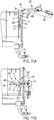
- FIGs 11A and 11B illustrate an embodiment of a discharge door latching system 80C for use with a discharge door 426 of a collection tank 14 of an earth excavator system, such as in Figure 1 , that is similar to the embodiment discussed with respect to Figures 9A and 9B , except that the lower end of the hydraulic cylinder is attached to the lower linkage arm at a point on the lower linkage arm offset from the lower linkage arm's pivotal connection to the tank body, rather than directly at the pivotal connection of the lower linkage arm to the tank body.
- discharge door latching system 80C includes two linkage assemblies 400, one on each side of tank 14.
- Each linkage assembly 400 includes an upper linkage arm 402, a lower linkage arm 404, and a linear actuator, in this instance a hydraulic cylinder, 460 having a cylinder housing 462 attached to lower linkage arm 404 and an extendable piston rod 464 attached to upper linkage arm 402.
- Cylinder housing 462 is pivotally attached to lower linkage arm 404 at a pinned connection 463 that is offset (along the length of the lower linkage arm) from the pivotal connection between the lower linkage arm and the tank body at pivot pin connection 410.
- cylinder housing 462 pivots about pinned connection 463 (about an axis extending into and out of the page of Figures 11A and 11B ), and also about axis 113, as the multi-armed linkage assembly moves between its extreme positions during its operation as disclosed herein.
- the linear actuator of the embodiment illustrated in Figures 11A and 11B are attached directly to and between the lower linkage arm and the upper linkage arm.
- the cylinder is attached at one operative end to the upper linkage arm and at its other operative end to the tank body via the lower linkage arm.
- the linear actuator is attached at a first operative end to one of the upper and lower linkage arms so that the first operative end moves with movement of the one of the upper and lower linkage arms and at its opposite second operative end to the tank body (in this instance, via the lower linkage arm so that the second operative end moves with the lower linkage arm) so that, when the door is closed over the tank body's open end, the axis about which the cylinder's second operative end moves with respect to the tank body is between the axis about which the cylinder's first operative end moves with respect to the one of the upper and lower linkage arm and the tank body open end.
- FIGs 12A, 12B , and 12C illustrate a discharge door latching system 80D for use with a discharge door 526 of a collection tank 14 of an earth excavator system 10, such as is also shown at Figure 1 .
- discharge door latching system 80D includes a linkage assembly 500 on both sides of tank 14, each having an upper linkage arm 502, a lower linkage arm 504, and a linear actuator, in this instance a hydraulic cylinder, 560 having a cylinder housing 562 mounted to lower linkage arm 504 and an extendable piston rod 564 mounted to upper linkage arm 502.
- latching system 80D differs from latching system 80 in that rather than attaching linkage assembly 500 adjacent an outer surface of tank body 15 of tank 14, linkage assembly 500 is mounted inside of tank 14, within internal chamber 111 (see, also, Figure 8 ).
- lower linkage arm 504 is attached to the tank body, not at an end of pivot bar 110 as in the embodiments of Figures 4-8 , but rather at the center of the support tube 115 (see also Figure 8 ).
- the through hole through lower linkage arm 504 may be fitted with a bearing assembly to facilitate the lower linkage arm's rotation about axis 113 that extends through the center of support tube 115, into and out of the page in the perspective of Figure 12B .
- Eye bolt 534 has an eye (not shown) that is pivotally attached in a pinned connection (a pin may be connected to the inner panel, e.g., by tabs welded to the panel) to the interior surface of the domed panel portion of door 526 (e.g. at the center of the domed panel) so that upper linkage arm 502 is pivotable with respect to door 526 about axis 132, which extends into and out of the page of the view of Figure 12B .
- the linear actuator's (in this instance, the hydraulic cylinder's) direction of operation is aligned entirely with the door's bias force direction when the door is closed against the tank's open end, as in the embodiment of Figures 4-8 .
- connection between the upper and lower linkage arms at axis 136 is between (when considered along the length of the upper linkage arm) the connection between the piston rod and the upper linkage arm at the axis of pinned connection 168
- the operation of the cylinder's extension and retraction in moving the multi-arm linkage between its extremes of position is the same as that of the embodiments of Figures 4-8 .
- the cylinder is attached at one operative end to the upper linkage arm and at its other operative end to the tank body via the lower linkage arm.
- the linear actuator is attached at a first operative end to one of the upper and lower linkage arms and at its opposite second operative end to the body so that, when the door is closed over the tank body's open end, the axis about which the cylinder's second operative end moves with respect to the tank body is between the axis about which the cylinder's first operative end moves with respect to the one of the upper and lower linkage arm and the tank body open end.
- hydraulic fluid lines may be directed through sealed openings in the tank body wall to reach the cylinder for its operation.
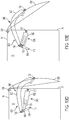
- FIGS 13A-13E illustrate a discharge door latching system 80E for use with a discharge door 626 of a collection tank 14 of an earth excavator system, such as is shown at Figure 1 .
- discharge door latching system 80E includes two linkage assemblies 600, one on each side of tank 14.
- Each linkage assembly 600 includes an upper linkage arm 602, a lower linkage arm 604, and a linear actuator, in this instance a hydraulic cylinder, 660 having a cylinder housing 662 attached to tank body 15 via a pinned connection at 611 (which may also be considered to define an axis 611 extending into and out of the page of the view of Figures 13A-13E and about which cylinder housing 662 pivotally moves as the multi-arm linkage assembly moves between its extreme positions) and an extendable piston rod 664 attached to lower linkage arm 604 at a pinned connection 168.
- Upper linkage arm 602 and lower linkage arm 604 are pivotally connected at a pinned connection that defines an axis 136 about which the upper and lower linkage arms pivot with respect to each other as they move through the motion driven by the linear actuator.
- First end 601 of upper linkage arm 602 is configured to adjustably receive a threaded portion of an eye bolt 134.
- Eye bolt 134 has an eye (not shown) that is pivotally connected to door 626, and more specifically to a first end of a cross bar (see, e.g., Figure 4 , at 148) that is rigidly secured to a domed panel of discharge door 126 so that the upper linkage arm is pivotable with respect to, and pivotally attached to, door 626 about an axis 132 that passes through the eyes of the eye bolts 134 on both sides of the tank body.
- Axis 132 is generally perpendicular to longitudinal axis 129 ( Figure 4 ) and is the axis about which door 626 (including the cross bar) pivots with respect to the first ends of the first and second upper linkage arms. Moreover, the threaded connection between upper linkage arm first end 601 and the corresponding end of the cross bar allows for adjustment of the space between the upper linkage arm first end and the cross bar end in the direction of the bias force vector applied by the door into the tank's open end periphery 74 (see also Figure 8 ).
- piston rod 664 is connected to lower linkage arm 604 at a pivotal (e.g. pinned) connection 168 that, when considered along the length of lower linkage arm 604, is between the point (axis 113) at which the lower linkage arm pivotally attaches to the tank body and the point (axis 136) at which the lower linkage arm pivotally attaches to the upper linkage arm.
- a pivotal (e.g. pinned) connection 168 that, when considered along the length of lower linkage arm 604, is between the point (axis 113) at which the lower linkage arm pivotally attaches to the tank body and the point (axis 136) at which the lower linkage arm pivotally attaches to the upper linkage arm.
- the hydraulic cylinder of the embodiment illustrated in Figures 13A-13E retracts in moving door 626 from its position closed over the open tank end to its opened position disposed away from the open tank end and extends in moving the door from the fully opened position to the fully closed position.
- the linear actuator is attached at a first operative end to one of the upper and lower linkage arms and at its opposite second operative end to the body so that, when the door is closed over the tank body's open end, the axis about which the cylinder's second operative end moves with respect to the tank body is between the axis about which the cylinder's first operative end moves with respect to the one of the upper and lower linkage arm and the tank body open end.
Landscapes
- Engineering & Computer Science (AREA)
- Mechanical Engineering (AREA)
- General Engineering & Computer Science (AREA)
- Health & Medical Sciences (AREA)
- Public Health (AREA)
- Transportation (AREA)
- Mining & Mineral Resources (AREA)
- Civil Engineering (AREA)
- Structural Engineering (AREA)
- Earth Drilling (AREA)
- Pressure Vessels And Lids Thereof (AREA)
- Component Parts Of Construction Machinery (AREA)
Abstract
Description
- This application claims the benefit of
U.S. Provisional Patent Application No. 63/040,394 filed June 17, 2020 - The present disclosure relates generally to a vacuum excavator system for removing soil to expose underground utilities (such as electrical and cable services, water and sewage services, etc.), and more particularly to an improved vacuum tank and door system for use with such system.
- With the increased use of underground utilities, it has become more important to locate and verify the placement of buried utilities before installation of additional underground utilities or before other excavation or digging work is performed. Conventional digging and excavation methods such as shovels, post hole diggers, powered excavators, and backhoes may be limited in their use in locating buried utilities as they may tend to cut, break, or otherwise damage the lines during use.
- Devices have been previously developed to create holes in the ground to non-destructively expose underground utilities to view. One design uses high pressure air delivered through a tool to loosen soil and a vacuum system to vacuum away dirt after it is loosened to form a hole. Another system uses high pressure water delivered by a tool to soften the soil and create a soil/water slurry mixture. The tool is connected with a vacuum system for vacuuming the slurry away into a collection tank. The tank may then be emptied by opening a door on the tank.
- Certain prior art vacuum systems are provided with a tank having a manually closing door that is locked in a closed position by latches, locks or other suitable locking mechanisms. Another example of a prior door system is presented in
U.S. Patent 7,837,050 , the entire disclosure of which is incorporated herein for all purposes. - An embodiment of the present disclosure provides a collection tank for a mobile vacuum excavator, including a generally cylindrical body having a front with a closed end, a rear with an open end having a periphery, a door having a periphery that abuts the periphery of the open end when the door is closed over the open end, and a linkage assembly having a first end attached to the door so that the first end moves with movement of the door and a second end attached to the body of the collection tank. The linkage assembly includes a first arm, a second arm pivotally attached to the first arm so that a first pivotal movement of the first arm and the second arm with respect to each other drives the first end and the second end away from each other and so that a second pivotal movement of the first arm and the second arm with respect to each other moves the first end and the second end toward each other. An actuator is attached to the first arm and to the second arm so that the actuator moves with movement of the first arm and with movement of the second arm and so that actuation of the actuator in a first direction moves the first arm and the second arm in the first pivotal movement and so that actuation of the actuator in a second direction moves the first arm and the second arm in the second pivotal movement.
- In another embodiment, a collection tank for a mobile vacuum excavator includes a generally cylindrical body including a front with a closed end, a rear with an open end having a periphery, a door having a periphery that abuts the periphery of the open end when the door is closed over the open end, and a linkage assembly having a first arm pivotally attached to the body at a mounting end about a mount axis, a second arm pivotally attached to the door at a mounting end about a door closure axis, so that the mounting end moves with movement of the door, and pivotally attached to the first arm at a door latch axis. A first pivotal movement of the first arm and the second arm with respect to each other drives the mounting end of the first arm and the mounting end of the second arm away from each other and a second pivotal movement of the first arm and the second arm with respect to each other drives the mounting end of the first arm and the mounting end of the second end toward each other, wherein the second arm has a distal end and wherein a door latch plane is defined by the mount axis and the door closure axis. A powered cylinder actuator is attached to the first arm and to the second arm so that the actuator moves with movement of the first arm and with movement of the second arm and so that retraction of the actuator moves the first arm and the second arm in the first pivotal movement and so that extension of the actuator in a second direction moves the first arm and the second arm in the second pivotal movement, wherein the door latch axis is on one side of the door latch plane when the actuator is in a retracted state and the door latch axis is on an opposite side of the door latch plane when the actuator is in an extended state.
- In a further embodiment, a collection tank for a mobile vacuum excavator has a generally cylindrical body having a front with a closed end, and a rear with an open end having a periphery. A door has a periphery that abuts the periphery of the open end when the door is closed over the open end. A linkage assembly has a first end attached to the door and a second end attached to the body. The linkage assembly comprises a first arm, a second arm pivotally attached to the first arm so that a first pivotal movement of the first arm and the second arm with respect to each other drives the first end and the second end away from each other and so that a second pivotal movement of the first arm and the second arm with respect to each other moves the first end and the second end toward each other, and a linear actuator attached at a first operative end of the linear actuator to one of the first arm and the second arm, so that the first operative end of the linear actuator moves with movement of the one of the first arm and the second arm, and at a second operative end of the linear actuator to the body proximate the second end of the linkage assembly so that actuation of the linear actuator in a first direction moves the first arm and the second arm in the first pivotal movement and so that actuation of the actuator in a second direction moves the first arm and the second arm in the second pivotal movement.
- In a still further embodiment, a collection tank for a mobile vacuum excavator has a generally cylindrical body having a front with a closed end, and a rear with an open end having a periphery. A door has a periphery that abuts the periphery of the open end when the door is closed over the open end. A linkage assembly has a first end attached to the door so that the first end moves with movement of the door and a second end attached to the body. The linkage assembly has a first arm, a second arm pivotally attached to the first arm so that a first pivotal movement of the first arm and the second arm with respect to each other drives the first end and the second end away from each other and so that a second pivotal movement of the first arm and the second arm with respect to each other moves the first end and the second end toward each other, and a linear actuator. The linear actuator is attached at a first operative end of the linear actuator to one of the first arm and the second arm so that the first operative end of the linear actuator is movable about a first axis during the first pivotal movement and the second pivotal movement and at a second operative end of the linear actuator to the body so that the second operative end of the linear actuator is movable about a second axis during the first pivotal movement and the second pivotal movement, and so that actuation of the linear actuator in a first direction moves the first arm and the second arm in the first pivotal movement and so that actuation of the linear actuator in a second direction moves the first arm and the second arm in the second pivotal movement. The linear actuator is attached to the one of the first arm and the second arm and to the body so that, when the door is closed over the open end, the second axis is between the open end and the first axis.
- In yet another aspect, a collection tank for a mobile excavator has a generally cylindrical body with a tank centerline, a front with a closed end, and a rear with an open end having a sealing flange that defines a first plane perpendicular to the tank centerline. A door is pivotally connected to the generally cylindrical body and has a periphery that abuts the sealing flange of the open end when the door is closed over the open end. A first linkage arm has an end pivotally connected to the body. A second linkage arm has a first end pivotally connected to the door and a second end. When the door is closed over the open end, the first end of the second linkage arm is rearward of the first plane and the second end of the second linkage arm is forward of the first plane. An actuator has a first end that is pivotally connected to one of the first linkage arm or the second linkage arm at a first pivot point lying in a third plane that is perpendicular to the tank centerline, and a second end having a second pivot point located between the first plane and the third plane. The first pivot point and the second pivot point lie in a plane that is parallel to or generally parallel to the tank centerline.
- A full and enabling description of the present disclosure, including the best mode thereof directed to one of ordinary skill in the art, is set forth in the specification, which makes reference to the appended figures, in which:
-
Figure 1 is a perspective view of a vacuum-operated earth excavator system including a collection tank door system in accordance with an embodiment of the present disclosure; -
Figure 2A is a side plan view of the vacuum-operated earth excavator system ofFigure 1 ; -
Figure 2B is a side plan view of the vacuum-operated earth excavator system as inFigure 2A , with certain components as inFigures 1 and2A omitted for view of a collection tank; -
Figure 2C is a side plan view of the vacuum-operated earth excavator system as inFigure 2A , viewed from a side of the system opposite of the view ofFigure 2a and with certain components as inFigures 1 and2A omitted for view of a collection tank; -
Figure 3A is a schematic view of the hydraulic, electric, water, and vacuum systems of the vacuum-operated earth excavator system ofFigures 1 and2 ; -
Figure 3B is a detail view of part of the system as shown inFigure 3A ; -
Figure 4 is a partial perspective view of the collection tank of the earth excavator shown inFigures 1 and2 , including a collection tank door system in accordance with an embodiment of the present disclosure, with certain components hidden; -
Figures 5A and5B are partial plan side views of the collection tank door system as shown inFigure 4 , in the closed position; -
Figure 6A and 6B are a partial perspective and a partial plan side view of the collection tank door system as shown inFigure 4 , in a partially open position; -
Figure 7 is a partial plan side view of the collection tank door system as shown inFigure 4 , in a fully open position; -
Figure 8 is a partial perspective view of the collection tank door system as shown inFigure 4 , in a fully open position; -
Figures 9A and 9B are partial plan side views of an embodiment of a collection tank, including a door system, in accordance with the present disclosure for use with an earth excavator system as atFigure 1 , with certain components hidden; -
Figures 10A and 10B are partial plan side views of an embodiment of a collection tank, including a door system, in accordance with the present disclosure for use with an earth excavation system as inFigure 1 , with certain components hidden; -
Figures 11A and 11B are partial plan side views of an embodiment of a collection tank, including a door system, in accordance with the present disclosure for use with an earth excavation system as inFigure 1 , with certain components hidden; -
Figures 12A, 12B , and12C are a rear view, a partial cross-sectional view, and a partial cross-sectional view of an embodiment of a collection tank, including a door system, in accordance with the present disclosure for use with an earth excavation system as inFigure 1 , with certain components hidden; and - Each of
Figures 13A, 13B, 13C ,13D, and 13E is a side schematic view of an embodiment of a door system in accordance with the present disclosure for use with a collection tank of an earth excavation system as inFigure 1 . - Repeat use of reference characters in the present specification and drawings is intended to represent same or analogous features or elements of the disclosure.
- Reference will now be made in detail to embodiments of the disclosure, one or more examples of which are illustrated in the accompanying drawings. Each example is provided by way of explanation of the disclosure, not limitation of the disclosure. In fact, it will be apparent to those skilled in the art that modifications and variations can be made in the present disclosure without departing from the scope and spirit thereof. For instance, features illustrated or described as part of one embodiment may be used on another embodiment to yield a still further embodiment. Thus, it is intended that the present disclosure covers such modifications and variations as come within the scope of the appended claims and their equivalents.
- It should be understood that terms of orientation, e.g. "forward," "rearward," "upper," "lower," "horizontal," "vertical," and similar terms as used herein are intended to refer to relative orientation of components of the devices described herein with respect to each other under an assumption of a consistent point of reference but do not require any specific orientation of the overall system. Thus, for example, the discussion herein may refer to a "forward" or "front" end of an earth excavation system or a generally cylindrical collection tank used therewith, referring to a direction toward the end of the earth excavator that has a motorized cab or that is configured in a trailer configuration to be attached to a vehicle rear end, or a "rearward" end of the earth excavation system or tank, referring to a direction toward the system's rear, at which the tank door is disposed and opens and closes against the open end of the tank. The present discussion may also refer to "upper" and/or "lower" surfaces of the earth excavation system and/or its components, generally with regard to the orientation of the system as shown in
Figures 1 and2 . Terms such as "horizontal" and "vertical," for example, refer to orientations under an assumption that an earth excavation system as inFigures 1 and2 is disposed in its operative position, such as shown at those figures, on a level, horizontal surface. Such terms may be used in the present disclosure and claims and will be understood to refer to a relative orientation but not to an orientation of the earth excavation system or its tank with respect to an external frame of reference. Further, the term "end" should be understood to encompass a part of something and an inward of a boundary or edge thereof, rather than just the boundary or edge. - Further, either of the terms "or" and "one of_ and _," as used in this disclosure and the appended claims, is intended to mean an inclusive "or" rather than an exclusive "or." That is, unless specified otherwise, or clear from the context, either of the phrases "X employs A or B" and "X employs one of A and B" is intended to mean any of the natural inclusive permutations. That is, either phrase is satisfied by any of the following instances: X employs A; X employs B; or X employs both A and B, and this is true of similar phrases, such as "at least one of A or B" or "at least one of A and B," that may be utilized in the specification or claims. In addition, the articles "a" and "an" as used in this application and the appended claims should generally be construed to mean "one or more" unless specified otherwise or clear from the context to be directed to a singular form. Throughout the specification and claims, the following terms take at least the meanings explicitly associated herein, unless the context dictates otherwise. The meanings identified below do not necessarily limit the terms, but merely provide illustrative examples for the terms. The meaning of "a," "an," and "the" may include plural references, and the meaning of "in" may include "in" and "on." The phrase "in one embodiment," as used herein does not necessarily refer to the same embodiment, although it may. Also, as used herein, the term "attach" means to fasten, join together. An attachment, therefore, may refer to a direct or an indirect connection between two or more things, and "attach," with respect to two or more components A and B, may refer to fastening/joining A and B to each other directly, so that they physically touch each other, or indirectly, so that they are joined to each other through one or more other components.
- Referring to
Figures 1 and2 (which should be understood to encompassFigures 2A ,2B , and2C ), anearth excavator system 10 generally includes a water reservoir tank (in this embodiment, a pair of tanks) 12, acollection tank 14, a motor 16 (which, in the illustrated embodiment may be the vehicle engine, delivering power through, e.g., a mechanical, hydraulic, or electric transmission system, but which may also be, e.g., a dedicated motor mounted on the chassis aft of the vehicle cab), and anearth removal system 18, all mounted on amobile chassis 24 that supports the various components. In the present embodiment,excavator system 10 includeschassis 24 of a motor vehicle 20 (which may also be considered part of the excavator system). It should be understood that while the hereindescribed components ofearth excavator system 10 are illustrated mounted onchassis 24 of a self-propelledmotor vehicle 20 with a dedicated motor that propels the apparatus, the system may also be supported on the chassis of a trailer (not shown) that can be towed or otherwise moved by a motorized vehicle such as a car, truck, or skid steer and that may therefore include a tongue and/or hitch coupler to connect to the separate vehicle. It should be understood that the components of the system may be either directly mounted to the chassis or indirectly mounted to the chassis through connections with other system components.Apparatus 10 includes a front 11, a rear 13, and alongitudinal axis 129 that extends throughfront 11 and rear 13. - The connections of the various components of
system 10 are illustrated schematically inFigure 3 . Referring toFigures 1 ,2 , and3 , thevacuum excavator system 10 includes a wand 4 (Fig. 3B ) for directing pressurized water W toward earthen material to cut the earthen material. Wand 4 is connected to an excavation fluid pump 6 that supplies water to wand 4 via a high-pressure water hose 70. Pump 6 may supply a pressure of, for example, at least about 500 psi or at least about 1,000 psi (e.g., from about 1,000 psi to about 5,000 psi or from 1,000 psi to about 3,000 psi). - In some embodiments, wand 4 includes a rotary nozzle 8 (
Fig. 3B ) for directing water W toward the earthen material to cut the earthen material. Generally, any rotary nozzle that causes the water to be directed toward the earthen material in a circular path at the site of the excavation may be used. Such rotary nozzles may include a rotor insert with blades that rotate around a longitudinal axis of the nozzle when water is forced through the nozzle. The rotor insert may include three or more channels that force fluid to flow in different pathways through the rotor insert to cause the water to move along a circular path as it contacts the excavation material (i.e., the water moves within a cone that extends from the nozzle toward the excavated material). In other embodiments, a straight tip nozzle that directs fluid along a straight path in a concentrated jet may be used. High-pressure water hose 70 is connected, via a valve, to fluid pump 6 to provide water to the earth removal system as selected by the user. As the system is used to dig a hole, a distal end of wand 4 is pressed downwardly into the ground. For larger diameter holes, wand 4 is moved in a generally circular manner as it is pressed downward, thereby removing material from a large cross-section area. Slurry formed in the hole is vacuumed through hose 5 and accumulates incollection tank 14. Once the excavation is completed and the utility is exposed, the vacuum system can be shut down, and the operators may examine or repair the utility as needed. -
Vacuum excavation system 10 includes a vacuum system 7 (Fig. 2A ) for removing spoil material from the excavation site. Spoil material or simply "spoils" may include, without limitation, rocks, cut earthen material (e.g., small particulate such as sand to larger pieces of earth that are cut loose by the jet of high pressure water), slurry, and water used for excavation. The spoil material may have a consistency similar to water, a slurry, or even solid earth, organic material, or rocks. The terms used herein for materials that may be processed by the vacuum excavation system such as, for example, "spoils," "spoil material," "cut earthen material" and "water," should not be considered in a limiting sense unless stated otherwise. - Vacuum system 7 includes a
vacuum pump system 33 and aboom 9 that is capable of rotating toward the excavation site to remove material from the excavation site.Boom 9 may include a flexible portion, such as a hose, 5 (Figs. 1 and3A ) that extends downward to the ground to vacuum spoil material from the excavation site. Flexible portion 5 may be manipulated by a user to direct the vacuum suction toward the excavation site. - Vacuum system 7 acts to entrain the cut earth and the water used to excavate the site in a stream of air. A blower or vacuum pump 31 (
Fig. 3A ) pulls a vacuum throughboom 9 to entrain the material in the airstream. Air is discharged from the blower 31 after material is removed from the airstream. - The airstream having water and cut earth entrained therein is pulled through
boom 9 and through a series of conduits and is pulled intocollection tank 14. Thecollection tank 14 removes at least a portion of cut earthen material and water from the airstream. Air exits one or more collectiontank air outlets 27 through one ormore conduits 25 and is introduced into cyclones 11 (Figs. 1 and3A ) viaconduit 25 to remove additional spoil material (e.g., water, small solids such as sand, low density particles such as sticks and grass, and the like) not separated in the collection tank. Material that collects in the bottom of thecyclones 11 is conveyed by a cyclone discharge pump (e.g., peristaltic pump) or, alternatively, is gravity fed to a dewatering system. The air removed fromcyclones 11 is introduced into one or more filter elements before entering vacuum pump 31. Vacuum pump 31 may be disposed in or near the engine compartment. Air is removed from the apparatus through avacuum exhaust 29. - Vacuum pump 31 generates vacuum in the system to pull water and cut earthen material into
system 10 for processing. In some embodiments, vacuum pump 31 is a positive displacement pump. Such positive displacement pumps may include dual-lobe or tri-lobe impellers (e.g., a screw rotor) that draw air into a vacuum side of the pump and forces air out the pressure side. The pump may be powered by a motor having a power output of, for example, at least 75 hp, at least 100 hp or even at least 125 hp. - One or more example vacuum excavation systems such as may be utilized with or encompassed by the systems and methods disclosed herein are disclosed in the
U.S. patent application serial no. 16/630,057 - Referring additionally to
Figure 4 ,collection tank 14 has a generallycylindrical body 15 having a closed front end 17 (Figures 2B and2C ) and open rear end 19 (Figure 8 ). Adischarge door 126 is connected to the openrear end 19 of thetank body 15 by ahinge 128 that allows thedoor 126 to swing open, thereby providing access to the tank's interior for cleaning. A pair of hydraulic cylinders may be provided for tilting the forward end oftank 14 upwards in order to cause the contents to run towardsdischarge door 126. Agate valve 140, coupled to adrain 142 indischarge door 126, drains the liquid portion of the slurry intank 14 without requiring the door to be opened.Gate valve 140 may also be used to introduce air intocollection tank 14 to reduce the vacuum in the tank so that thedoor 126 may be more easily opened. - Optionally running the length of the interior of
collection tank 14 is a nozzle tube that includes nozzles for directing high pressure water about the interior of the tank, and particularly towards the base of the tank. The nozzles are actuated by opening a valve connected to a water pump (e.g. water pump 6), which delivers high pressure water from the pump to the nozzles for producing a vigorous cleaning action in the tank. When the nozzles are not being used for cleaning, a small amount of water is allowed to continuously drip through the nozzles to pressurize them so as to prevent dirt and slurry from entering and clogging the nozzles. - The hydraulic cylinders, used to tilt
collection tank 14, may be powered, e.g., by an electric hydraulic pump (not shown) provided for the purpose, by the power source (engine) of the truck, or by the independent power source for the vacuum. The hydraulic pump connects to a hydraulic reservoir and is driven by the electrical system provided from the motor. A high-pressure output line and a return line connect the hydraulic pump to the hydraulic cylinders. -
Earth excavator system 10 can be used to dig multiple holes before having toempty collection tank 14. However, oncecollection tank 14 is full, it can be emptied at an appropriate dump site. When ready to opendischarge door 126, vacuum pump 31 is shut down, and the vacuum pressure is released so that air enters the tank, thereby allowing the internal pressure of the tank to match the ambient atmospheric pressure and allowing the door to be opened. Once the door is opened, the hydraulic cylinders can be activated to raise forward end 17 (Figure 2 ) upward, dumping the slurry from the tank. For this purpose,tank 14 is pivotally attached to chassis 24 (Figures 1 and2 ) at a pair ofhinges Figure 4 ) transverse toaxis 129 to allowtank 14 to pivot aboutaxis 88 as the hydraulic cylinders move the tank's forward end up and down, and such that when the hydraulic cylinders push the tank's forward end upward, liquid and solid matter retained incollection tank 14 may be discharged through the tank's open end. - Referring now to
Figures 4 ,5A , and5B ,collection tank 14 is equipped with a sealingflange 74 that defines a perimeter about the tank body's open end 19 (Figure 8 ),discharge door 126 that is pivotally connected to the tank body by a pair of slotted hinges 128, and a dischargedoor latching system 80.Hinges 128 are slotted hinges, thereby allowing the portions of the hinges on the door to move slightly back and forth on the hinge pins in the direction ofaxis 129 asdoor 126 pivots to and away from the tank opening. Asdoor 126 moves upward in the opening direction, hinges 128 allow the door's slight movement to allow the door's edge to clear the tank open edge. Asdoor 126 moves down in the closing direction, hinges 128 allow the door to move back in the other direction so that the door seats evenly against the tank open end periphery. - Discharge
door latching system 80 has twolinkage assemblies linkage assembly 100A, where all reference numbers are annotated with a capital "A." However, it should be understood that the same components exist forlinkage assembly 100B, as a mirror image oflinkage assembly 100A. - As should be understood, a linear actuator is an actuator that creates motion in a straight line, which may be referred to as the actuation dimension. Examples of linear actuators include, but are not limited to, mechanical actuators (such as screws, rack and pinion devices, belt drives, hydraulic cylinders, and pneumatic actuators), electro-mechanical actuators, and linear motors. Thus, while hydraulic cylinders are used in the examples described herein, it should be understood that this is for purposes of example only and that other linear and nonlinear actuators may be used to drive one or more linkage assemblies as discussed herein.
- Referring specifically to
Figure 5A , alower linkage arm 104A is rigidly connected to a linkage assembly pivot bar 110 (Figure 8 ) at the pivot bar'sfirst end 110A so that the lower linkage arm and the pivot bar rotate together. As shown,lower linkage arm 104A is connected to pivotbar 110 at a portion oflower linkage arm 104A that is disposed between afirst end 105A and asecond end 107A of the lower linkage arm.Pivot bar 110 extends from itsfirst end 110A, through the outer wall of collection tank body 15 (Figures 2 and4 ), and into a pivot bar/support tube 115 (Figure 8 ) that passes through an internal chamber 111 (Figure 8 ) oftank 14. The pivot bar is pivotable about anaxis 113 oriented generally parallel to an inner diameter of internal chamber 111 (Figure 8 ) ofcollection tank 14. The pivot bar extends along its axis 113 (which is also the pivot bar's elongation dimension) through tankinternal chamber 111 and further extends through the opposite side of the collection tank outer wall and terminates at a second end of thepivot bar 110. In embodiments in which thepivot bar 110 extends through the tankinternal chamber 111, without a support tube 115 (which may be sealingly attached to through holes through the tank wall to receive the bar), a sealed bearing (not shown) may rotatably engagepivot bar 110 at the point where thepivot bar 110 passes through the collection tank external wall to ensure that tank internal chamber 111 (Figure 8 ) remains sealed from the outside atmosphere. As shown inFigure 8 , pivot bar/support tube 115 spans interior 111 oftank 14 and provides structural support to the walls of thetank 14. In other embodiments, both thepivot bar 110 and thesupport tube 115 may be provided, though not necessarily one within the other as in the embodiments illustrated herein. The rigid connection oflower linkage arms Figure 8 ) with the respective first and second ends ofpivot bar 110 entrains both of the lower linkage arms withpivot bar 110 so that thelower linkage arms pivot bar 110. In another embodiment,pivot bar 110 may be omitted, though the tubing through which it passes may be retained, e.g., for structural support. In such embodiments, each of the two lower linkage arms may be pivotally attached to the tank wall, e.g. about a pin welded or bolted to the tank wall or received within a receiver manufactured into the tank wall. -
First end 105A of firstlower linkage arm 104A has an actuating cylinder mounting hole (not shown) adjacent its distal end. In one or more embodiments, actuatingcylinder 160A is a hydraulic cylinder having acylinder housing 162A and apiston rod 164A that is slidably received inhousing 162A.Piston rod 164A has afree end 166A that is pivotally attached to acylinder mounting hole 152A formed at the distal end of asecond end 103A of firstupper linkage arm 102A, e.g. by apin 168A that extends through both a hole throughfree end 166A andcoaxial hole 152A. The end ofcylinder housing 162A is similarly pivotally attached, e.g. by apin 169A passing through the actuating cylinder mounting hole (not shown) formed infirst end 105A of firstlower linkage arm 104A and a coaxial hole through the end ofcylinder housing 162A.Pins free end 166A andcylinder housing 162A to the respective cylinder mounting holes by clevis, eyebolt or other similar pivotal linkages. - Referring specifically to
Figure 4 ,upper linkage arm 102A has aforward portion 121 formed in two opposing halves that form a yoke that receives arearward portion 123. The open rearward end offorward portion 121 receives the forward end ofrearward portion 123, and the two ends are fastened to each other, such as by weldment, so that the two portions form a continuous upper linkage arm. The yoke-type or yoke-shaped arrangement offorward portion 121 allows theforward end 107A oflower linkage arm 104A to be received within/between the two yoke halves and, thereby, allows for pivotal connection between the upper and lower linkage arms to be made by apin 144A that passes through both arms, as explained below. Similarly, the forwardfree end 166A (Figure 5A ) ofcylinder piston rod 164A is also received within/between the two halves of the yoke end of the upper linkage arm so thatpin 168A (Figure 5A ) passes through the two yoke halves throughcorresponding holes 152A and through a hole through forwardfree end 166A (Figure 5A ) of the cylinder piston rod to pivotally attach the hydraulic cylinder to the upper linkage arm. By such arrangement, the linear actuator, the lower linkage arm, and the upper linkage arm are stacked sequentially with respect to each other in the vertical direction. Thus, for example, actuatingcylinder 160A is mounted belowupper linkage arm 102A and belowlower linkage arm 104A, which is in turn mounted belowupper linkage arm 102A, such that a vertical plane, indicated at 125 inFig. 4 , simultaneously passes through the linear actuator, the lower linkage arm, and the upper linkage arm, whereplane 125 may be considered to be parallel to the center line (or longitudinal axis) 129 of generallycylindrical tank body 15 or to include the dimension of the force vector applied bydoor 126 to peripheral flange 74 (Figure 5A ) when the door is closed over the tank open end and the locking force is applied thereto, as described herein. Accordingly, the linear actuator is attached to one of the lower linkage arm and the upper linkage arm and to the tank body so that, when the door is closed over the tank open end, the lower linkage arm, the upper linkage arm, and the linear actuator are disposed with respect to each other so that a plane passes through each of the upper linkage arm, the lower linkage arm, and the linear actuator and includes a direction of bias of the door periphery into the periphery of the tank open end. This stacking arrangement minimizes the distance thatlinkage assembly 100A (and, similarly,linkage assembly 100B) extends horizontally outward from thetank body 15, thereby allowing a tank diameter that remains within a predetermined overall system width limit but that is larger than would be the case where the linear actuator, the lower linkage arm, and/or the upper linkage arm are not stacked vertically with respect to each other. - Returning to
Figures 4 ,5A , and5B ,pivot pin 144A pivotally connects first lower linkage armsecond end 107A with a portion ofupper linkage arm 102A that is disposed between itsfirst end 101A andsecond end 103A, thereby allowing the upper and lower linkage arms to pivot with respect to each other about anaxis 136 that passes throughpivot pins Axis 136 is generally perpendicular tolongitudinal axis 129 and is the axis about whichupper linkage arms lower linkage arms First end 101A ofupper linkage arm 102A is configured to adjustably receive a threaded portion of aneye bolt 134A.Eye bolt 134A has an eye (not shown) that is pivotally connected todoor 126, and more specifically to afirst end 146A of across bar 148 that is rigidly secured to a domed panel ofdischarge door 126 so that the upper linkage arm is pivotable with respect todoor 126 about anaxis 132 that passes through the eyes of botheye bolts 134A and 134B.Axis 132 is generally perpendicular tolongitudinal axis 129 and is the axis about which door 126 (including cross bar 148) pivots with respect to the first ends of the first and second upper linkage arms. Moreover, the threaded connection between upper linkage armfirst end 101A and cross barfirst end 146A allows for adjustment of the space between the upper linkage arm first end and the cross bar first end in the direction of the bias force vector applied by the door into the tank's open end periphery 74 (Figure 8 ). -
Figures 7 and8 illustratecollection tank 14 withdischarge door 126 in a fully open position, in whichpiston rod 164A ofactuating cylinder 160A (and the piston rod of the opposinglinear actuator 160B) is in the retracted position.Linkage assemblies pivot bar 110 cooperate withhinges 128 to rotatedischarge door 126 between this fully opened position and the sealing engagement withcollection tank flange 74 in the door's fully closed position. When closing the discharge door from its fully open position, actuatingcylinder 160A begins to extendpiston rod 164A. Thepivotal pin connection 168A between piston rodfree end 166A (Figure 5A ) andsecond end 103A ofupper linkage arm 102A forcesupper linkage arm 102A to pivot in the clockwise (CW)direction 154 about pivot point 144A whereupper linkage arm 102A is pivotably connected tolower linkage arm 104A. Simultaneously,lower linkage arm 104A begins to pivot in the counter-clockwise (CCW)direction 156 aboutaxis 113 ofpivot bar 110. Continued extension ofpiston rod 164A by actuatingcylinder 160A causesdischarge door 126 to be similarly rotated in theCW direction 154 abouthinges 128, as shown inFigure 6B . - With reference also to
Figure 2C , actuatingcylinder 160B ofsecond linkage assembly 100B simultaneously extendspiston rod 164B as actuatingcylinder 160A extendspiston rod 164A, resulting in closing force being applied simultaneously both tolower linkage arms bar 110. In certain embodiments, and depending upon the strength of the actuating cylinders and the linkage arms, actuatingcylinders bar 110, when provided. In such embodiments, whenpivot bar 110 is used, one of the actuating cylinders may be omitted without altering the function of the discharge door. For example, in an embodiment including only one actuating cylinder, such asfirst actuating cylinder 160A, a rigid connection between the second lower linkage armfirst end 105B and pivot barsecond end 110B forces secondlower linkage arm 104B to simultaneously rotate in response to the extension of actuatingcylinder 160A. Moreover, in such embodiments where two actuating cylinders are provided, should one of the actuating cylinders fail during operation, the other can operate the opening and closing of the door so as to maintain the system's functional integrity. It should be understood that the lower linkage arms do not necessarily need to be rigidly attached to pivotbar 110 but, instead, may be independently (with respect to each other) rotatably attached to the tank body, obviating the need for the pivot bar. Thus, in this configuration, each actuating cylinder would drive its respective lower linkage arm independently of the other actuating cylinder. In certain embodiments, the actuation cylinders may not be sufficiently strong for one of the cylinders to independently drive both linkage assemblies simultaneously. In such and other embodiments, the pivot bar may serve to synchronize the motions of the two linkage assemblies. - In operation, and referring again to
Figures 2C ,7 , and8 , aslower linkage arms direction 156, allowing upper linkage arm first ends 101A and 101B to move downward withdoor 126 as first and secondupper linkage arms pins door 126 rotates downward abouthinges 128 in the direction ofarrow 154 by way of the rigid connection betweencross bar 148 and the domed portion ofdischarge door 126. Rotation ofdischarge door 126 about door hinges 128 causes dischargedoor 126 to rotate into closing engagement with collectiontank sealing flange 74. - As best seen in
Figure 6B , extension ofpiston rods lower linkage arms axis 113 ofpivot bar 110 inCCW direction 156 as first and secondupper linkage arms Figure 8 ) rotate aboutpivot points Figures 6A and 6B showdischarge door 126 in a position between the fully open and fully closed position aspiston rods Discharge door 126 has aflange 127 about its outer periphery that forms a sealed engagement withcollection tank flange 74 once the discharge door is fully closed. It should be understood that a gasket (not shown) may be attached to one oftank flange 74 ordoor flange 127 to assist in forming an airtight seal when the door in the closed position. - Referring to
Figures 2C ,4 ,5A , and5B , once dischargedoor flange 127 seats withtank flange 74,actuating cylinders piston rods upper linkage arm 102A makes contact with a portion of the upper surface oflower linkage arm 104A (at 108A -Fig. 5B ) forming a rotational stop. The mirror image structure exists withinlinkage assembly 100B on the opposite side oftank 14. In another embodiment, in which rotational stop 108A is not provided via contact between the upper and lower linkage arms, the rotational stop may comprise a seating bracket (not shown) attached to the side wall oftank body 15 that receiveslinkage assembly 100A. A similar seating bracket on the opposing side oftank body 15 similarly receiveslinkage assembly 100B. Whenlinkage assemblies - A discharge door locking feature of latching
system 80 is now discussed. For purposes of discussion,axis 136 ofpivot points axis 132 between the upper linkage arm and the door is referred to as the "door closure axis;"axis 113 ofpivot bar 110, i.e. the axis of rotation between the lower linkage arm and the tank body, is referred to as the "mount axis;" and mountaxis 113 and its paralleldoor closure axis 132 define a door latch plane 180 (Fig. 5B ). As best seen inFigure 5B , rotational stop 108A (and a corresponding rotational stop 108B, not shown, defined in the linkage assembly on the tank's opposite side in mirror image) is positioned such that the bottom surface ofupper linkage arm 102A contacts the upper surface oflower linkage arm 104A only whendoor latch axis 136 crosses from a position abovedoor latch plane 180 to a position belowdoor latch plane 180. This condition may be referred to as "rotation beyond over center," andFigure 5B showslinkage assembly 100A when placed in this position. Because of the simultaneous movement of bothlinkage assembly 100A andlinkage assembly 100B, both linkage assemblies respond identically as they rotate over center. - When
door latch axis 136 lies in door latch plane 180 (plane 180 moves from its horizontal position shown inFigure 5B as the multi-arm linkage assemblies move),upper linkage arm 102A is in tension, andlower linkage arm 104A is in compression, and the forces can be reduced by movingdoor latch axis 136 out ofdoor latch plane 180 in either the opening direction abovedoor latch plane 180 or in the closing direction belowdoor latch plane 180. By forcing door latch axis 136 (andpivot points discharge door 126 is biased into the closed position and will remain in the closed position unlesslower linkage arms door latch plane 180 to a position abovedoor latch plane 180. In embodiments without stops 108A/B, the actuator may prevent further rotational movement. - Note, when the discharge door contacts the open end of the tank during the closure of
discharge door 126, the force exerted by actuatingcylinder 160A on the door is in a direction away from the door. That is, in moving the door into closing contact with the tank's open end, the force exerted by actuatingcylinder 160A (and, correspondingly, by the actuating cylinder on the tank body's opposing side) on the door through the linkage assemblies is in a direction that biases the discharge door toward the tank body's open end. When the door is in the closed position, the force is parallel to axis 129 (Figure 4 ). - As apparent in the embodiment illustrated at
Figure 5B , ifdoor latch axis 136 is above (in the perspective ofFigure 5B )door latch plane 180, then whenupper linkage arm 102A andlower linkage arm 104A (and, correspondingly,upper linkage arm 102B andlower linkage arm 104B) move pivotally with respect to each other so thatdoor latch axis 136 moves in direction 156 (Figures 6B and7 ) anddoor 127 moves in the closing direction indicated at 154 inFigure 7 ,first end 101A ofupper linkage arm 102A andfirst end 105A oflower linkage arm 104A (and, correspondinglyfirst end 101B ofupper linkage arm 102B andfirst end 105B oflower linkage arm 104B) move toward each other. Again ifdoor latch axis 136 is abovedoor latch plane 180, then whenupper linkage arm 102A andlower linkage arm 104A (and, correspondingly,upper linkage arm 102B andlower linkage arm 104B) move pivotally with respect to each other so thatdoor latch axis 136 moves in the rotational direction opposite to direction 156 (Figures 6B and7 ) anddoor 127 moves in the opening direction opposite to the direction indicated at 154 inFigure 7 ,first end 101A ofupper linkage arm 102A andfirst end 105A oflower linkage arm 104A (and, correspondinglyfirst end 101B ofupper linkage arm 102B andfirst end 105B oflower linkage arm 104B) move away from each other. Afterdoor latch axis 136 passes over center from above to belowdoor latch plane 180,first end 101A ofupper linkage arms 102A andfirst end 105A oflower linkage arm 104A (and, correspondingly,first end 101B ofupper linkage arm 102B andfirst end 105B oflower linkage arm 104B) move slightly apart until stops 108A/B prevent further rotational movement. As will be understood in view of the present disclosure, this slight movement does not disengagedoor 126 from its engagement with the tank open end perimeter. Similarly, whenaxis 136 moves in the opposite, opening, CW direction from such position and towardplane 180, first ends 101A/B and 105A/B move slightly toward each other untilaxis 136 crosses from below to aboveplane 180, from which point they move away from each other as the door opens. -
Actuating cylinders - When opening
discharge door 126 from the closed position, actuatingcylinder 160A retractspiston rod 164A inwardly, causing pivot points 144A, 144B andaxis 136 to rotate aboutaxis 113 in a direction opposite to arrow 156 (Figure 7 ) to a position abovedoor latch plane 180. This rotation causesupper actuating arm 102A to pivot in the CCW direction aboutaxis 136 ofpivot points lower actuating arm 102A begins to rotate in the CW direction aboutmount axis 113. As previously noted, actuatingcylinder 160B may simultaneously retractpiston rod 164B as actuatingcylinder 160A retracts itspiston rod 164A, resulting in a similar opening force applied toupper linkage arms Figure 6B ). If provided, pivot bar 110 (Figure 8 ) also rotates, synchronizing the movements oflinkage assemblies - As actuating
cylinder 160A is disposed between upper andlower linkage arms tank body 15. Additionally, attaching both operative ends of the cylinder directly to the linkage arms avoids the need to include components for directly attaching the cylinder to the tank body. Moreover, in embodiments in which one end of the actuating cylinder is attached directly to the tank body, but proximate the attachment to the lower linkage arm, a relatively short stroke may still be obtained. - It should be understood that while, in certain embodiments, the hydraulic cylinder is attached to and between one of the upper linkage arm and the lower linkage arm, and the linkage arms are attached to the door and the tank, so that the hydraulic cylinders move the door in the opening direction when the cylinders themselves move in a retracting direction and move the door in the closing direction when the cylinders themselves move in an extending direction, this is for purposes of example only and not limitation of the present disclosure. In other embodiments, the linkage arms may be arranged between the door and the tank body, and the hydraulic cylinders (or other linear actuators) may be arranged between the tank body and the multi-arm linkage assemblies (or within the multi-arm linkage assemblies) so that actuation of the cylinders in the extending direction moves the door in the opening direction and actuation of the cylinders in the retracting direction moves the door in the closing direction. Similarly, while one or more embodiments illustrated or discussed herein provide a linear actuator attached between the tank body and the upper linkage arm to drive the door between the extremes of its movement range, it should be understood from the present disclosure that the linear actuators may be attached between the tank wall and the lower linkage arm for the same purpose. Thus, again, the particular one or more embodiments disclosed herein are for purposes of example and should not be considered to limit the present disclosure.
- In one or more embodiments, when
discharge door 126 is in the closed position, the linear actuator is oriented so that its direction of operation is generally aligned with the closing or sealing force of the door into the peripheral edge flange 74 (Figure 8 ), generally parallel with the tank body's cylindrical axis 129 (Figure 4 ). For example, referring toFigure 5A , aplane 175 that includes the pivot axis throughpin 168A (and corresponding pin in the linkage assembly on the opposing side of the tank body) about whichupper linkage arm 102A pivots with regard to piston rodfree end 166A and that includes the pivot axis throughpin 169A (and corresponding pin in the linkage assembly on the opposing side of the tank body) about which the opposing end of the linear actuator is pivotally attached to the lower linkage arm includes the door's bias or force direction (horizontal, in the view ofFigure 5A ) and is parallel to tank axis 129 (Figure 4 ). This arrangement is achieved through the positioning of the axis ofpin 169A vertically belowaxis 113 by the flange of the lower linkage arm extending between those positions. As shown inFigure 5A , there is a (slightly smaller) vertical offset betweenaxis 136 and the axis ofpivot pin 168A. Thus, the lower linkage arm flange extending belowaxis 113 locates the axis ofpin 169A so that it aligns horizontally with the axis ofpin 168A, thereby horizontally aligning the cylinder's operational dimension. In other embodiments, a plane passing through the two pivot axes of the linear actuator may be generally parallel (e.g., plus or minus 10 degrees from parallel) to the tank axis 129 (Figures 9B ,10B ,11B ,12B ,13A ). - As previously stated, the above discussion is directed primarily to
linkage assembly 100A. However, one of skill in the art should understand, in view of the discussion herein, that the discussion also reflects the construction and operation oflinkage assembly 100B (Figure 4 ), in mirror image. Moreover, while not shown in the figures, one of skill in the art should understand thatlinkage assemblies - As noted above, the embodiments described above with respect to
Figures 4-8 attach the linear actuator to and between the two arms of each of the two dual arm linkage assemblies so that the linear actuator moves with movement of both arms of the linkage assembly. In such arrangements, and others discussed herein, the actuator has a relatively short stroke in driving the tank door between the extremes of its range of travel with respect to the tank open end. The linear actuator's disposition in these embodiments, and others disclosed herein, also locate the linear actuator sufficiently closely with the multi-arm linkage assembly that space below the multi-arm linkage assembly is available to secure other components of the system, e.g. the pneumatic hose used to draw slurry into the collection tank of the earth excavator. In certain embodiments described herein, the linear actuator may be attached at one end to one of the upper linkage arm and the lower linkage arm so that the linear actuator moves with movement thereof and at its other end directly to the tank body, though proximate the multi-arm linkage assembly's attachment to the tank, and have a relatively short stroke and allow for the placement of system components under the multi-arm linkage assemblies. Thus, for example with respect toFigures 10A and 10B , alinear actuator 360 may be attached at a first operative end of the linear actuator (at 361) to one of the two linkage arms (e.g. upper linkage arm 302) at a second operative end of the linear actuator (at 311) to the tank body proximate the second end of the linkage assembly (attached to the tank body at axis 113) so that actuation oflinear actuator 360 in a first direction moves the twolinkage arms - In certain embodiments described herein, for example with respect to
Figure 5A , consider the attachment between one end of the linear actuator and the tank body (at 169A), so that a first end of the linear actuator is movable about a pivot point and first axis (the axis throughpin 169A coming out of the page, in the perspective ofFigure 5A ) that is perpendicular to the generally cylindrical tank's center axis 129 (Figure 4 ), and the attachment between the second end of the linear actuator (at 168A) and one of the upper linkage arm and the lower linkage arm (in the example ofFigure 5A ,upper linkage arm 102A), so that the linear actuator's second end is movable (with respect to the linkage arm to which it is attached, in thisinstance linkage arm 102A) about a pivot point and second axis (the axis throughpin 168A coming out of the page, in the perspective ofFigure 5A ) that is perpendicular to the tank center axis. Whendoor 326 is in its closed position against the open tank end, the first axis is between the second axis and the tank open end. The axis (coming out of and into the page) atpin 169A is between the parallel axis throughpin 168A and the tank's open end. It should be noted that the first axis is between the second axis and the open tank end, e.g., because, on a line (in the page ofFigure 5A ) passing through both axes and the door opening, the first axis (atpin 169A) is between the other axis (atpin 168A) and the open end, on that line. "Between," however, does not require that the three features be so aligned. Thus, e.g., if the tank door opening is considered with respect to a verticalfirst plane 310 that includesdoor opening periphery 74 and that is perpendicular to the tank center line 129 (Figure 4 ), and the first axis (atpin 169A) is considered with respect to a verticalsecond plane 312 that includes the first axis and is perpendicular to the tank centerline, and the second axis (atpin 168A) is considered with respect to a verticalthird plane 314 that includes the second axis and that is perpendicular to the tank centerline, then the first axis is between the second axis and the tank open end becausesecond plane 312 is betweenfirst plane 310 andthird plane 314. One or more of the embodiments discussed below may also illustrate such features. -
Figures 9A and 9B illustrate, e.g., a dischargedoor latching system 80A for use with adischarge door 226 of acollection tank 14 of an earth excavator system, such as is shown atFigure 1 . Similar to the embodiments of dischargedoor latching system 80 previously discussed with regard toFigures 4 through 8 , dischargedoor latching system 80A includes twolinkage assemblies 200, one on each side ofcollection tank 14. Eachlinkage assembly 200 includes anupper linkage arm 202, alower linkage arm 204, and a linear actuator, in this instance a hydraulic cylinder, 260 having acylinder housing 262 attached to tank body 15 (via the same mounting location by which the lower linkage arm is attached to the tank body) and anextendable piston rod 264 attached toupper linkage arm 202. In the embodiment ofFigures 9A and 9B , the hydraulic cylinder's attachment to the lower linkage arm and the lower linkage arm's point of attachment to the tank body are joined at thepoint 210 where the lower linkage arm pivotally attaches to the tank body aboutaxis 113. Thus,cylinder housing 262 pivots aboutaxis 113 both with respect to the tank body and with respect tolower linkage arm 204 as the multi-arm linkage assembly moves between its operative extreme positions. The free end ofpiston rod 264 is connected toupper linkage arm 202 at a pivotal (e.g. pinned)connection 261 that, when considered along the length ofupper linkage arm 202, is between the point (axis 136) at which the upper linkage arm pivotally attaches to the lower linkage arm and the point (axis 132) at which the upper linkage arm pivotally attaches to the door, resulting in reversal of the cylinder's operation directions from that of the embodiments ofFigures 4-8 . - In operation, assume that
door 226 is disposed in its fully open position as shown inFigure 9A . As illustrated in the Figure,cylinder 260 is in its fully extended position. To close the door, the hydraulic control system that controls the cylinder is actuated to cause the cylinder to retract. Since the lower end ofcylinder housing 262 is fixed to the tank body at 210, the pinnedconnection 261 betweencylinder rod 264 andupper linkage arm 202 allowsupper linkage arm 202 to pivot downward in the CW direction aboutaxis 136 with respect to lower linkage arm 204 (in response to the actuator movement and the door's weight). Simultaneously,lower linkage arm 204 pivots in the CCW direction aroundaxis 113, with the result thataxis 136 moves in the CCW direction aboutaxis 113. Retraction of the cylinder to its fully retracted position, as illustrated inFigure 9B , drawsaxis 136 over center with respect to the plane defined byaxes door 226 seated against periphery 74 (Figure 8 ) about the tank's open end. To open the door from this position, the cylinder's hydraulic controls are operated to cause it to extend. This pushesupper linkage arm 202 so that it moves in the CW direction aboutaxis 132 and in the CCW direction about itsaxis 136, and pulls the lower linkage arm (through the pinned connection at axis 136) in the CW direction aboutaxis 113 and the CCW direction aboutaxis 136. The resulting movement ofaxis 132 to the right (in the perspective ofFigure 9B ) causes the door to open about the axis of hinges 128. -
Figures 10A and 10B illustrate an embodiment of a dischargedoor latching system 80B for use with adischarge door 326 of acollection tank 14 of an earth excavator system, such as inFigure 1 , that is similar to the embodiment discussed with respect toFigures 9A and 9B , except that the lower end of the hydraulic cylinder is attached to the tank body via a pivotal connection to a bracket attached to the tank body that is not coincident withaxis 113, rather than via the pivotal connection of the lower linkage arm to the tank body. Similar to the embodiments of dischargedoor latching system 80 previously discussed with regard toFigures 4 through 8 , dischargedoor latching system 80B includes twolinkage assemblies 300, one on each side oftank 14. Eachlinkage assembly 300 includes anupper linkage arm 302, alower linkage arm 304, and a linear actuator, in this instance a hydraulic cylinder, 360 having acylinder housing 362.Cylinder housing 362 is attached to the tank body via a pivotal connection to abracket 363 that is affixed to the side wall oftank body 15, rather than via the pivotal connection oflower linkage arm 304 to the tank body. The cylinder'sextendable piston rod 364 is pivotally attached toupper linkage arm 302 through a pivot pin connection at 361. Whilecylinder housing 362 is pivotally attached to the tank body about an axis 311 (extending into and out of the page ofFigures 10A and 10B ) of a pivot pin connection, the pivotal connection between the cylinder housing and the tank at 311 remains proximate the position at which one end of the linkage assembly (in this instance, the lower linkage arm) attaches to the tank body. In this embodiment and the embodiments ofFigures 4-8 (seeFigure 5A ) and9A-9B (seeFigure 9A ), the linear actuator is attached at a first operative end to one of the upper and lower linkage arms and at its opposite second operative end to the tank body so that, when the door is closed over the tank body's open end, the axis about which the cylinder's second operative end moves with respect to the tank body is between the axis about which the cylinder's first operative end moves with respect to the one of the upper and lower linkage arm and the tank body open end. The operation of the embodiment illustrated inFigures 10A and 10B in moving the multi-arm linkage between its extreme positions is similar to the corresponding operation of the embodiment ofFigures 9A and 9B . -
Figures 11A and 11B illustrate an embodiment of a dischargedoor latching system 80C for use with adischarge door 426 of acollection tank 14 of an earth excavator system, such as inFigure 1 , that is similar to the embodiment discussed with respect toFigures 9A and 9B , except that the lower end of the hydraulic cylinder is attached to the lower linkage arm at a point on the lower linkage arm offset from the lower linkage arm's pivotal connection to the tank body, rather than directly at the pivotal connection of the lower linkage arm to the tank body. Similar to the embodiments of dischargedoor latching system 80 previously discussed with regard toFigures 4 through 8 , dischargedoor latching system 80C includes twolinkage assemblies 400, one on each side oftank 14. Eachlinkage assembly 400 includes anupper linkage arm 402, alower linkage arm 404, and a linear actuator, in this instance a hydraulic cylinder, 460 having acylinder housing 462 attached tolower linkage arm 404 and anextendable piston rod 464 attached toupper linkage arm 402.Cylinder housing 462 is pivotally attached tolower linkage arm 404 at a pinnedconnection 463 that is offset (along the length of the lower linkage arm) from the pivotal connection between the lower linkage arm and the tank body atpivot pin connection 410. Thus,cylinder housing 462 pivots about pinned connection 463 (about an axis extending into and out of the page ofFigures 11A and 11B ), and also aboutaxis 113, as the multi-armed linkage assembly moves between its extreme positions during its operation as disclosed herein. - Like the embodiments described with respect to
Figures 4-8 , the linear actuator of the embodiment illustrated inFigures 11A and 11B are attached directly to and between the lower linkage arm and the upper linkage arm. In this embodiment and the embodiments ofFigure 4-8 and9A-9B , the cylinder is attached at one operative end to the upper linkage arm and at its other operative end to the tank body via the lower linkage arm. In this embodiment and the embodiment ofFigures 4-8 ,9A-9B , and10A-10B , the linear actuator is attached at a first operative end to one of the upper and lower linkage arms so that the first operative end moves with movement of the one of the upper and lower linkage arms and at its opposite second operative end to the tank body (in this instance, via the lower linkage arm so that the second operative end moves with the lower linkage arm) so that, when the door is closed over the tank body's open end, the axis about which the cylinder's second operative end moves with respect to the tank body is between the axis about which the cylinder's first operative end moves with respect to the one of the upper and lower linkage arm and the tank body open end. - The operation of the embodiment illustrated in
Figures 11A and 11B is similar to the operation of the embodiment illustrated inFigures 9A and 9B , referenced above. -
Figures 12A, 12B , and12C illustrate a discharge door latching system 80D for use with adischarge door 526 of acollection tank 14 of anearth excavator system 10, such as is also shown atFigure 1 . Similarly to the embodiments of dischargedoor latching system 80 previously discussed with regard toFigures 4 through 8 , discharge door latching system 80D includes alinkage assembly 500 on both sides oftank 14, each having anupper linkage arm 502, alower linkage arm 504, and a linear actuator, in this instance a hydraulic cylinder, 560 having a cylinder housing 562 mounted to lowerlinkage arm 504 and an extendable piston rod 564 mounted toupper linkage arm 502. The connection points betweenupper linkage arm 502,lower linkage arm 504, and actuatingcylinder 560 oflinkage assembly 500 are the same as those of upper linkage arm 102, lower linkage arm 104, and actuating cylinder 160 of linkage assembly 100 of the embodiments ofFigures 4-8 (see, e.g.,Figure 5A ). However, latching system 80D differs from latchingsystem 80 in that rather than attachinglinkage assembly 500 adjacent an outer surface oftank body 15 oftank 14,linkage assembly 500 is mounted inside oftank 14, within internal chamber 111 (see, also,Figure 8 ). In this embodiment,lower linkage arm 504 is attached to the tank body, not at an end ofpivot bar 110 as in the embodiments ofFigures 4-8 , but rather at the center of the support tube 115 (see alsoFigure 8 ). The through hole throughlower linkage arm 504 may be fitted with a bearing assembly to facilitate the lower linkage arm's rotation aboutaxis 113 that extends through the center ofsupport tube 115, into and out of the page in the perspective ofFigure 12B . - The end of
upper linkage arm 502 opposite the upper linkage arm's end that attaches to lowerlinkage arm 504 at the pinned connection that definesaxis 136 is configured to adjustably receive a threaded portion of aneye bolt 534.Eye bolt 534 has an eye (not shown) that is pivotally attached in a pinned connection (a pin may be connected to the inner panel, e.g., by tabs welded to the panel) to the interior surface of the domed panel portion of door 526 (e.g. at the center of the domed panel) so thatupper linkage arm 502 is pivotable with respect todoor 526 aboutaxis 132, which extends into and out of the page of the view ofFigure 12B . - Because, in this embodiment, the (a) vertical offset between (i) the connection between the first end of the linear actuator and the upper linkage arm at 168 and (ii) the connection between the two linkage arms at
axis 136 and (b) the vertical offset between (iii) the connection between the second end of the linear actuator and the lower linkage arm at the axis through 169 and (iv) the connection between the lower linkage arm and the tank body ataxis 113 aligns the hydraulic cylinder horizontally when the door closes on the tank's open end, the linear actuator's (in this instance, the hydraulic cylinder's) direction of operation is aligned entirely with the door's bias force direction when the door is closed against the tank's open end, as in the embodiment ofFigures 4-8 . Because, in this embodiment, the connection between the upper and lower linkage arms ataxis 136 is between (when considered along the length of the upper linkage arm) the connection between the piston rod and the upper linkage arm at the axis of pinnedconnection 168, the operation of the cylinder's extension and retraction in moving the multi-arm linkage between its extremes of position is the same as that of the embodiments ofFigures 4-8 . In this embodiment, the cylinder is attached at one operative end to the upper linkage arm and at its other operative end to the tank body via the lower linkage arm. The linear actuator is attached at a first operative end to one of the upper and lower linkage arms and at its opposite second operative end to the body so that, when the door is closed over the tank body's open end, the axis about which the cylinder's second operative end moves with respect to the tank body is between the axis about which the cylinder's first operative end moves with respect to the one of the upper and lower linkage arm and the tank body open end. It will be understood that hydraulic fluid lines may be directed through sealed openings in the tank body wall to reach the cylinder for its operation. -
Figures 13A-13E illustrate a dischargedoor latching system 80E for use with adischarge door 626 of acollection tank 14 of an earth excavator system, such as is shown atFigure 1 . Similar to the embodiments of dischargedoor latching system 80 previously discussed with regard toFigures 4 through 8 , dischargedoor latching system 80E includes twolinkage assemblies 600, one on each side oftank 14. Eachlinkage assembly 600 includes anupper linkage arm 602, alower linkage arm 604, and a linear actuator, in this instance a hydraulic cylinder, 660 having acylinder housing 662 attached totank body 15 via a pinned connection at 611 (which may also be considered to define anaxis 611 extending into and out of the page of the view ofFigures 13A-13E and about whichcylinder housing 662 pivotally moves as the multi-arm linkage assembly moves between its extreme positions) and anextendable piston rod 664 attached tolower linkage arm 604 at a pinnedconnection 168.Upper linkage arm 602 andlower linkage arm 604 are pivotally connected at a pinned connection that defines anaxis 136 about which the upper and lower linkage arms pivot with respect to each other as they move through the motion driven by the linear actuator. -
First end 601 ofupper linkage arm 602 is configured to adjustably receive a threaded portion of aneye bolt 134.Eye bolt 134 has an eye (not shown) that is pivotally connected todoor 626, and more specifically to a first end of a cross bar (see, e.g.,Figure 4 , at 148) that is rigidly secured to a domed panel ofdischarge door 126 so that the upper linkage arm is pivotable with respect to, and pivotally attached to,door 626 about anaxis 132 that passes through the eyes of theeye bolts 134 on both sides of the tank body.Axis 132 is generally perpendicular to longitudinal axis 129 (Figure 4 ) and is the axis about which door 626 (including the cross bar) pivots with respect to the first ends of the first and second upper linkage arms. Moreover, the threaded connection between upper linkage armfirst end 601 and the corresponding end of the cross bar allows for adjustment of the space between the upper linkage arm first end and the cross bar end in the direction of the bias force vector applied by the door into the tank's open end periphery 74 (see alsoFigure 8 ). - The free end of
piston rod 664 is connected to lowerlinkage arm 604 at a pivotal (e.g. pinned)connection 168 that, when considered along the length oflower linkage arm 604, is between the point (axis 113) at which the lower linkage arm pivotally attaches to the tank body and the point (axis 136) at which the lower linkage arm pivotally attaches to the upper linkage arm. Like the embodiments ofFigures 4-8 , the hydraulic cylinder of the embodiment illustrated inFigures 13A-13E retracts in movingdoor 626 from its position closed over the open tank end to its opened position disposed away from the open tank end and extends in moving the door from the fully opened position to the fully closed position. - The linear actuator is attached at a first operative end to one of the upper and lower linkage arms and at its opposite second operative end to the body so that, when the door is closed over the tank body's open end, the axis about which the cylinder's second operative end moves with respect to the tank body is between the axis about which the cylinder's first operative end moves with respect to the one of the upper and lower linkage arm and the tank body open end.
- In operation, assume that
door 626 is disposed in its fully open position as shown inFigure 13E . As illustrated in the Figure,cylinder 660 is in its fully retracted position. To close the door, the hydraulic control system that controls the cylinder is actuated to cause the cylinder to extend. Since the lower end ofcylinder housing 262 is fixed to the tank body at 611, this causespiston rod 664 to pushlower linkage arm 604 in the CCW direction aboutaxis 113, thereby causingupper linkage arm 602 to pivot in the CW direction aboutaxis 136 with respect tolower linkage arm 204, with the result thataxis 136 moves in the CCW direction aboutaxis 113 and thatdoor 626 pivots in the CW direction about the axis (in and out of the page of these figures) defined by hinges 128. Extension of the cylinder to its fully extended position, as illustrated inFigure 13A , drawsaxis 136 over center with respect to a plane 675 (coming into and out of the page ofFigure 13A ) defined byaxes door 226 seated against periphery 74 (see also,Figure 8 ) about the tank's open end. To open the door from this position, the cylinder's hydraulic controls are operated to cause it to retract. This pullslower linkage arm 602 so that so that it moves in the CW direction aboutaxis 113 and pushes the upper linkage arm (through the pinned connection at axis 136) in the CCW direction aboutaxis 136. This causes the door to open to the right (in the perspective ofFigures 13A - 13E ) and the door to thereby pivot in the CCW direction about the axis of the door hinges 128. The resulting movement ofaxis 132 to the right (in the perspective ofFigures 13A-13E ) causes the door to open about the axes of thehinges 128 to the fully opened position, as shown atFigure 13E . - It should be appreciated by those skilled in the art that various modifications and variations can be made in the present disclosure without departing from the scope and spirit of the disclosure. It is intended that the present disclosure cover such modifications and variations as come within the scope and spirit of the appended claims and their equivalents.
- Features of the invention:
- Feature 1. A collection tank for a mobile vacuum excavator, the collection tank comprising:
- a generally cylindrical body having
- a front with a closed end, and
- a rear with an open end having a periphery;
- a door having a periphery that abuts the periphery of the open end when the door is closed over the open end; and
- a linkage assembly having a first end attached to the door so that the first end moves with movement of the door, and a second end attached to the body, wherein the linkage assembly comprises
- a first arm,
- a second arm pivotally attached to the first arm so that a first pivotal movement of the first arm and the second arm with respect to each other drives the first end and the second end relatively away from each other, and so that a second pivotal movement of the first arm and the second arm with respect to each other moves the first end and the second end relatively toward each other, and
- an actuator attached to the first arm and to the second arm so that the actuator moves with movement of the first arm and with movement of the second arm and so that actuation of the actuator in a first direction moves the first arm and the second arm in the first pivotal movement, and so that actuation of the actuator in a second direction moves the first arm and the second arm in the second pivotal movement.
- Feature 2. The collection tank of feature 1, wherein the first arm is attached to the body at the first end of the linkage assembly, and wherein the second arm is attached to the door at the second end of the linkage assembly.
- Feature 3. The collection tank of the previous features, wherein the actuator is a hydraulic cylinder.
- Feature 4. The collection tank of the previous features, wherein the actuator is attached to the first arm and the second arm so that the first direction corresponds to retraction of the hydraulic cylinder and so that the second direction corresponds to extension of the hydraulic cylinder.
- Feature 5. The collection tank of the previous features, wherein the first arm and the second arm are disposed with respect to each other so that, when the door moves to a closed position with respect to the collection tank, a pivotal attachment between the first arm and the second arm moves over center.
- Feature 6. The collection tank of the previous features, wherein the first arm is pivotally attached to the body at a body mounting end about a mount axis, the second arm is pivotally attached to the door at a door mounting end about a door closure axis, so that the door mounting end moves with movement of the door, and the second arm is pivotally attached to the first arm at a door latch axis so that a first pivotal movement of the first arm and the second arm with respect to each other drives the body mounting end of the first arm and the door mounting end of the second arm relatively away from each other, and so that a second pivotal movement of the first arm and the second arm with respect to each other drives the body mounting end of the first arm and the door mounting end of the second arm relatively toward each other,
wherein a door latch plane is defined by the mount axis and the door closure axis, and wherein the door latch axis is on one side of the door latch plane when the actuator is in a retracted state and the door latch axis is on an opposite side of the door latch plane when the actuator is in an extended state.
Claims (15)
- A collection tank (14) for a mobile vacuum excavator (20), the collection tank (14) comprising:a generally cylindrical body (15) having
a tank centerline (129);
a front with a closed end (17); and
a rear with an open end (19) having a sealing flange (74) that defines a first plane (310) perpendicular to the tank centerline (129);a door (126, 226, 326, 426, 526, 626) pivotally connected to the generally cylindrical body (15) and having a periphery that abuts the sealing flange (74) of the open end (19) when the door (126, 226, 326, 426, 526, 626) is closed over the open end (19);a first linkage arm (104, 204, 304, 404, 504, 604) having an end (105A) pivotally connected to the body (15);a second linkage arm (102, 202, 302, 402, 502, 602) having a first end (101A) pivotally connected to the door (126, 226, 326, 426, 526, 626) and a second end (103A), wherein when the door (126, 226, 326, 426, 526, 626) is closed over the open end (19), the first end (101A) of the second linkage arm (102, 202, 302, 402, 502, 602) is rearward of the first plane (310) and the second end (103A) of the second linkage arm (102, 202, 302, 402, 502, 602) is forward of the first plane (310); andan actuator (160, 260, 360, 460, 560, 660) having
a first end that is pivotally connected to one of the first linkage arm (104, 204, 304, 404, 504, 604) or the second linkage arm (102, 202, 302, 402, 502, 602) at a first pivot point (168A, 261, 361, 466, 168) lying in a third plane (314) that is perpendicular to the tank centerline (129); and
a second end having a second pivot point (169A, 113, 311, 466, 169, 611) located between the first plane (310) and the third plane (314);
wherein the first pivot point (168A, 261, 361, 466, 168) and the second pivot point (169A, 113, 311, 466, 169, 611) lie in a plane (175) that is parallel to or generally parallel to the tank centerline (129). - The collection tank (14) of claim 1, wherein the first linkage arm (104, 204, 304, 404, 504, 604) and the second linkage arm (102, 202, 302, 402, 502, 602) are pivotally attached to one another such that a first pivotal movement of the first linkage arm (104, 204, 304, 404, 504, 604) and the second linkage arm (102, 202, 302, 402, 502, 602) with respect to each other drives the first end (101A) of the second linkage arm (102, 202, 302, 402, 502, 602) and the end (105A) of the first linkage arm (104, 204, 304, 404, 504, 604) relatively away from each other, and so that a second pivotal movement of the first linkage arm (104, 204, 304, 404, 504, 604) and the second linkage arm (102, 202, 302, 402, 502, 602) with respect to each other moves the first end (101A) of the second linkage arm (102, 202, 302, 402, 502, 602) and the end (105A) of the first linkage arm (104, 204, 304, 404, 504, 604) relatively toward each other.
- The collection tank (14) of claim 2, wherein the actuator (160, 260, 360, 460, 560, 660) is attached to the first linkage arm (104, 204, 304, 404, 504, 604) and to the second linkage arm (102, 202, 302, 402, 502, 602) so that the actuator (160, 260, 360, 460, 560, 660) moves with movement of the first linkage arm (104, 204, 304, 404, 504, 604) and with movement of the second linkage arm (102, 202, 302, 402, 502, 602), and so that actuation of the actuator (160, 260, 360, 460, 560, 660) in a first direction moves the first linkage arm (104, 204, 304, 404, 504, 604) and the second linkage arm (102, 202, 302, 402, 502, 602) in the first pivotal movement, and so that actuation of the actuator (160, 260, 360, 460, 560, 660) in a second direction moves the first linkage arm (104, 204, 304, 404, 504, 604) and the second linkage arm (102, 202, 302, 402, 502, 602) in the second pivotal movement.
- The collection tank (14) of any of the previous claims, wherein the first linkage arm (104, 204, 304, 404, 604), the second linkage arm (102, 202, 302, 402, 502, 602), and the actuator (160, 260, 360, 460, 660) together define a linkage assembly (100A, 200, 300, 400, 600) that is disposed on a first side of the collection tank (14), and further comprising a second linkage assembly (100B, 200, 300, 400, 600) attached to and between the door (126, 226, 326, 426, 626) and the body (15) on a second side of the collection tank (14), opposite the first side.
- The collection tank (14) of any of the previous claims, wherein the first linkage arm (504), the second linkage arm (502), and the actuator (560) together define a linkage assembly (500) that is disposed inside the body (15).
- The collection tank (14) of any of the previous claims, wherein
the first linkage arm (104, 204, 304, 404, 504, 604) is pivotally attached to the body (15) at a body mounting end about a mount axis (113),
the second linkage arm (102, 202, 302, 402, 502, 602) is pivotally attached to the door (126) at a door mounting end about a door closure axis (132), so that the door mounting end moves with movement of the door (126), and the second linkage arm (102, 202, 302, 402, 502, 602) is pivotally attached to the first linkage arm (104, 204, 304, 404, 504, 604) at a door latch axis (136), so that a first pivotal movement of the first linkage arm (104, 204, 304, 404, 504, 604) and the second linkage arm (102, 202, 302, 402, 502, 602) with respect to each other drives the body mounting end of the first linkage arm (104, 204, 304, 404, 504, 604) and the door mounting end of the second linkage arm (102, 202, 302, 402, 502, 602) relatively away from each other, and so that a second pivotal movement of the first linkage arm (104, 204, 304, 404, 504, 604) and the second linkage arm (102, 202, 302, 402, 502, 602) with respect to each other drives the body mounting end of the first linkage arm (104, 204, 304, 404, 504, 604) and the door mounting end of the second linkage arm (102, 202, 302, 402, 502, 602) relatively toward each other,
wherein a door latch plane (180) is defined by the mount axis (113) and the door closure axis (132), and
wherein the door latch axis (136) is on one side of the door latch plane (180) when the actuator (160, 260, 360, 460, 560, 660) is in a retracted state, and the door latch axis (136) is on an opposite side of the door latch plane (180) when the actuator (160, 260, 360, 460, 560, 660) is in an extended state. - The collection tank (14) of any of the previous claims, wherein each of the first linkage arm (104, 204, 304, 404, 504, 604), the second linkage arm (102, 202, 302, 402, 502, 602), and the actuator (160, 260, 360, 460, 560, 660) lie in a common plane.
- The collection tank (14) of any of the previous claims, wherein the second linkage arm (102, 202, 302, 402, 502, 602) is formed with a yoke-shaped end configured to receive at least a portion of the first linkage arm (104, 204, 304, 404, 504, 604) therein.
- The collection tank (14) of claim 8, wherein each of the first linkage arm (104, 204, 304, 404, 504, 604) and the actuator (160, 260, 360, 460, 560, 660) are pivotally attached to the yoke-shaped end of the second linkage arm (102, 202, 302, 402, 502, 602) such that at least a portion of the first linkage arm (104, 204, 304, 404, 504, 604) and at least a portion of the actuator (160, 260, 360, 460, 560, 660) are positioned between yoke-halves of the yoke-shaped end.
- The collection tank (14) of any of the previous claims, wherein the first linkage arm (104, 204, 304, 404, 504, 604) and the second linkage arm (102, 202, 302, 402, 502, 602) are disposed with respect to each other so that, when the door (126, 226, 326, 426, 526, 626) moves to a closed position with respect to the collection tank (14), a pivotal attachment between the first linkage arm (104, 204, 304, 404, 504, 604) and the second linkage arm (102, 202, 302, 402, 502, 602) moves over center.
- The collection tank (14) of any of the previous claims, wherein the door (126, 226, 326, 426, 626) has a dome-shaped panel and has an elongated cross bar (148) rigidly connected to the dome-shaped panel, and wherein the second linkage arm (102, 202, 302, 402, 602) is attached to the door through the elongated cross bar (148).
- The collection tank (14) of any of the previous claims, wherein the first end of the actuator (160, 260, 360, 460, 560, 660) is pivotally connected to the second linkage arm (102, 202, 302, 402, 502, 602).
- The collection tank (14) of any of the previous claims, wherein the first end of the actuator (160, 260, 360, 460, 560, 660) is pivotally connected to the first linkage arm (104, 204, 304, 404, 504, 604).
- The collection tank (14) of any of the previous claims, wherein the actuator (160, 260, 360, 460, 560, 660) is a hydraulic cylinder.
- The collection tank (14) of any of the previous claims, further comprising a hinge (128) between the body (15) and the door (126, 226, 326, 426, 526, 626).
Priority Applications (1)
| Application Number | Priority Date | Filing Date | Title |
|---|---|---|---|
| EP23180549.0A EP4242406B1 (en) | 2020-06-17 | 2021-06-14 | Vacuum excavator tank and door system |
Applications Claiming Priority (1)
| Application Number | Priority Date | Filing Date | Title |
|---|---|---|---|
| US202063040394P | 2020-06-17 | 2020-06-17 |
Related Child Applications (2)
| Application Number | Title | Priority Date | Filing Date |
|---|---|---|---|
| EP23180549.0A Division-Into EP4242406B1 (en) | 2020-06-17 | 2021-06-14 | Vacuum excavator tank and door system |
| EP23180549.0A Division EP4242406B1 (en) | 2020-06-17 | 2021-06-14 | Vacuum excavator tank and door system |
Publications (2)
| Publication Number | Publication Date |
|---|---|
| EP3926104A1 true EP3926104A1 (en) | 2021-12-22 |
| EP3926104B1 EP3926104B1 (en) | 2023-08-09 |
Family
ID=76444307
Family Applications (2)
| Application Number | Title | Priority Date | Filing Date |
|---|---|---|---|
| EP21179220.5A Active EP3926104B1 (en) | 2020-06-17 | 2021-06-14 | Vacuum excavator tank and door system |
| EP23180549.0A Active EP4242406B1 (en) | 2020-06-17 | 2021-06-14 | Vacuum excavator tank and door system |
Family Applications After (1)
| Application Number | Title | Priority Date | Filing Date |
|---|---|---|---|
| EP23180549.0A Active EP4242406B1 (en) | 2020-06-17 | 2021-06-14 | Vacuum excavator tank and door system |
Country Status (4)
| Country | Link |
|---|---|
| US (2) | US11801785B2 (en) |
| EP (2) | EP3926104B1 (en) |
| AU (1) | AU2021203940B2 (en) |
| CA (1) | CA3122003A1 (en) |
Families Citing this family (9)
| Publication number | Priority date | Publication date | Assignee | Title |
|---|---|---|---|---|
| US11801785B2 (en) * | 2020-06-17 | 2023-10-31 | Vermeer Manufacturing Company | Vacuum excavator tank and door system |
| US12077362B2 (en) | 2021-08-06 | 2024-09-03 | Ryan Peterkin | Transportable self contained cutting box |
| US11772884B2 (en) | 2021-08-06 | 2023-10-03 | Ryan Peterkin | Pressure vessel device |
| US10933794B1 (en) * | 2020-10-02 | 2021-03-02 | Magtec Alaska, LLC | Heated slurry transport system |
| US11396419B1 (en) * | 2021-08-06 | 2022-07-26 | Magtech Alaska, LLC | Cold steel slurry box device |
| US20230042517A1 (en) * | 2021-08-06 | 2023-02-09 | Ryan Peterkin | Transportable Slurry Box Method of Use |
| CA3208388A1 (en) * | 2022-08-22 | 2024-02-22 | Nuhn Industries Ltd. | Door assembly for a manure holding tank |
| WO2025199342A1 (en) | 2024-03-22 | 2025-09-25 | Vermeer Manufacturing Company | Vacuum excavator coupling |
| US12466643B1 (en) * | 2024-10-31 | 2025-11-11 | Trans-West, Inc. | Systems and methods for removing particulate material |
Citations (4)
| Publication number | Priority date | Publication date | Assignee | Title |
|---|---|---|---|---|
| US7837050B2 (en) | 2006-10-06 | 2010-11-23 | McLaughlin Group, Inc | Collection tank |
| US20150291350A1 (en) * | 2011-05-02 | 2015-10-15 | The Charles Machine Works, Inc. | Apparatus For Sealing A Vacuum Tank Door |
| US20170292306A1 (en) * | 2016-04-06 | 2017-10-12 | The Charles Machine Works, Inc. | Vacuum System |
| US20180327999A1 (en) * | 2017-05-12 | 2018-11-15 | The Charles Machine Works, Inc. | Mobile Vacuum System |
Family Cites Families (77)
| Publication number | Priority date | Publication date | Assignee | Title |
|---|---|---|---|---|
| US2144586A (en) | 1933-01-13 | 1939-01-17 | Kadco Corp | Method of rock drilling and dust removal therefor |
| US2122517A (en) | 1937-01-02 | 1938-07-05 | Cleveland Rock Drill Co | Dust eliminator |
| US2250670A (en) | 1939-01-20 | 1941-07-29 | Joy Mfg Co | Drilling apparatus |
| US2507522A (en) | 1944-08-31 | 1950-05-16 | Koehring Co | Mixer |
| US2448546A (en) | 1945-09-04 | 1948-09-07 | Lawrence M Plemel | Portable recompression chamber |
| US2480692A (en) | 1946-05-01 | 1949-08-30 | Howard E Anthony | Inspection cover |
| US2639601A (en) | 1949-12-15 | 1953-05-26 | Miller Herman | Swingable door for tumbler type clothes washing machines |
| US2562551A (en) | 1950-09-01 | 1951-07-31 | Worthington Pump & Mach Corp | Closure door assembly for concrete mixers or agitators |
| DK121338B (en) | 1967-09-05 | 1971-10-04 | J Lildal | Maneuvering mechanism for the cover for the discharge opening in a so-called dry melter. |
| US3713472A (en) | 1971-11-17 | 1973-01-30 | Gen Motors Corp | Vehicle closure system |
| US3768203A (en) | 1972-01-26 | 1973-10-30 | Amsco Ind Co | Closure operating structure |
| SE363071B (en) | 1972-05-08 | 1974-01-07 | Von Tell Trading Co Ab | |
| US3968845A (en) | 1973-01-15 | 1976-07-13 | Chaffin John D | Apparatus and method for geological drilling and coring |
| US3842461A (en) | 1973-05-15 | 1974-10-22 | Walkee Vacuum Services Ltd | Industrial vacuum apparatus |
| US4155586A (en) | 1976-08-16 | 1979-05-22 | Super Products Corporation | Tailgate locking system |
| US4119238A (en) | 1977-07-05 | 1978-10-10 | Sundstrand Corporation | Container closure having opening means |
| US4307541A (en) | 1979-11-30 | 1981-12-29 | Dempster Systems Inc. | Tail-gate operating and locking mechanism |
| US4322868A (en) | 1980-09-11 | 1982-04-06 | Super Products Corporation | Sewer and catch basin cleaner |
| US4434861A (en) | 1981-01-07 | 1984-03-06 | Howeth David Franklin | Dust conveying and collecting system and method |
| US4334633A (en) | 1981-04-06 | 1982-06-15 | Wsf Industries, Inc. | Articulated door |
| US4510714A (en) | 1982-09-30 | 1985-04-16 | The Boeing Company | Powered outward-opening cargo door |
| US4518095A (en) | 1984-06-01 | 1985-05-21 | Fresh Tech, Inc. | Door assembly |
| US4659262A (en) | 1985-03-04 | 1987-04-21 | Cyclonaire Bulk Cargo Systems, Inc. | Mobile self contained pneumatic conveying system |
| DE8511617U1 (en) | 1985-04-19 | 1985-06-05 | Wirth Maschinen- und Bohrgeräte-Fabrik GmbH, 5140 Erkelenz | Manipulator for lid locking parts |
| JPH0513896Y2 (en) | 1985-06-06 | 1993-04-13 | ||
| US4842223A (en) | 1988-03-09 | 1989-06-27 | The United States Of America As Represented By The Administrator Of The National Aeronautics And Space Administration | Hatch cover |
| US5092963A (en) | 1989-02-21 | 1992-03-03 | Atlantic Richfield Company | Automated top head and stem guide assembly for coking drums |
| US5016717A (en) | 1989-03-14 | 1991-05-21 | Aqua-Vac Locators, Inc. | Vacuum excavator |
| US4975205A (en) | 1989-05-03 | 1990-12-04 | Subaqueous Services, Inc. | Apparatus and method for receiving, draining and disposing of dredged material |
| US4936031A (en) | 1989-10-12 | 1990-06-26 | Acb Technology, Corp. | Apparatus for excavating soil and the like using supersonic jets |
| CH684402A5 (en) | 1991-03-04 | 1994-09-15 | Xorella Ag Wettingen | Device for sliding and pivoting of a container-closure. |
| US5141528A (en) | 1991-03-27 | 1992-08-25 | Super Products Corporation | Separator docking system |
| US5140759A (en) | 1991-06-14 | 1992-08-25 | M-B-W Inc. | Pneumatic device for excavating and removing material |
| US5295317A (en) | 1992-09-17 | 1994-03-22 | Perrott Kenneth W | Apparatus for excavating earthen material by evacuation of same |
| US5287602A (en) | 1992-11-13 | 1994-02-22 | Delaware Capital Formation, Inc. | Powered toggle latch clamp |
| US5299370A (en) | 1992-11-25 | 1994-04-05 | Badger Daylighting Inc. | Excavation apparatus |
| DE4306135A1 (en) | 1993-02-27 | 1994-09-01 | Vmb Vesta Maschbau Gmbh & Co | Suction dredger |
| US5408766A (en) | 1993-04-28 | 1995-04-25 | Pobihushchy; Victor | Hydraulic excavating machine |
| US5487229A (en) | 1993-05-28 | 1996-01-30 | Electric Power Research Institute, Inc. | Apparatus for pneumatic excavation |
| US5515625A (en) | 1993-08-05 | 1996-05-14 | Hydroseed Manufacturing, Incorporated | Rake attachment with scarifying teeth for a skid steer |
| US5500976A (en) | 1993-09-08 | 1996-03-26 | Cyclone Surface Cleaning, Inc. | Mobile cyclonic power wash system with water reclamation and rotary union |
| US5860232A (en) | 1995-12-06 | 1999-01-19 | Concept Engineering Group, Inc. | Mobile safe excavation system having a deflector plate and vacuum source |
| US5791073A (en) | 1996-11-12 | 1998-08-11 | Filtration Manufacturing, Inc. | Vacuum excavation system |
| US5996171A (en) | 1997-02-04 | 1999-12-07 | Bowers; Randy | Vacuum truck system |
| US6000151A (en) | 1997-03-04 | 1999-12-14 | Hayes; Paul | Vacuum excavation apparatus having an improved air lance, air lance nozzle, and vacuum system including a multistage venturi ejector |
| USD423521S (en) | 1997-08-29 | 2000-04-25 | Gehl Company | Skid steer loader |
| US6202330B1 (en) | 1998-04-23 | 2001-03-20 | Bolton Corporation | Excavation assembly, apparatus and method of operating the same |
| AUPP786598A0 (en) | 1998-12-23 | 1999-01-21 | Jaden Charters Pty Ltd | Improved skid-steer vehicle |
| US6517292B1 (en) | 1999-09-01 | 2003-02-11 | Richard E Landau | Apparatus to form columns of granular material |
| US6386598B1 (en) | 1999-09-07 | 2002-05-14 | Delaware Capital Formation, Inc. | Locking power clamp |
| US6273512B1 (en) | 1999-09-09 | 2001-08-14 | Robert C. Rajewski | Hydrovac excavating blast wand |
| US6360458B2 (en) | 1999-10-26 | 2002-03-26 | Farmers' Factory Company | Rake attachment for skid steer loaders and front end loaders and method for converting a loader bucket into a lawn preparation tool |
| US6615849B1 (en) | 1999-11-16 | 2003-09-09 | John William Gilman | Tank cleaning system |
| US6470605B1 (en) | 1999-11-16 | 2002-10-29 | John William Gilman | Earth reduction tool |
| US6499934B1 (en) | 2000-05-12 | 2002-12-31 | Clark Equipment Company | Implement attachment bracket for skid steer loader mounting plate |
| US6604304B1 (en) | 2000-10-06 | 2003-08-12 | Slabach Enterprises, Inc. | Dual mode evacuation system for vacuum excavator |
| US7503134B2 (en) | 2000-11-27 | 2009-03-17 | Buckner Lynn A | Inclined slope vacuum excavation container |
| US6988568B2 (en) | 2000-11-27 | 2006-01-24 | Lynn Allan Buckner | Vacuum boring and mud recovery system |
| US7644523B2 (en) | 2000-11-27 | 2010-01-12 | Lynn Allan Buckner | Mobile vacuum boring and excavation method |
| US6997667B2 (en) | 2002-11-13 | 2006-02-14 | Skid Mor Development Llc | Material handling apparatus and method for operating |
| US20040108317A1 (en) | 2002-12-09 | 2004-06-10 | Don Martin Buckner | Vacuum container inside closure means for the access door |
| US8066140B1 (en) | 2003-02-28 | 2011-11-29 | The Charles Machine Works, Inc. | Container door and container door latching and sealing system |
| US6996935B1 (en) | 2003-06-24 | 2006-02-14 | Meyer Manufacturing Corporation | Gate regulator |
| US7415748B1 (en) | 2004-01-22 | 2008-08-26 | Mclaughlin Group, Inc. | Vacuum implement for use with a skid steer |
| CA2479443C (en) | 2004-08-16 | 2009-04-21 | Victor Pobihushchy | Vacuum truck solids handling apparatus |
| US7484322B2 (en) | 2004-10-22 | 2009-02-03 | Mclaughlin Group, Inc. | Digging and backfill apparatus |
| US7234252B2 (en) | 2004-10-25 | 2007-06-26 | Jarnecke Dennis R | Method and apparatus for beneficiating soils during vacuum excavation |
| ATE463386T1 (en) | 2005-08-23 | 2010-04-15 | Stag Ag | CLOSING DEVICE FOR FILLER NECKS ARRANGED ON A CONTAINER |
| US20070261309A1 (en) | 2006-05-10 | 2007-11-15 | The Stanley Works | Automatic door assembly with telescoping door arm |
| US7743537B2 (en) | 2006-10-05 | 2010-06-29 | Mclaughlin Group, Inc. | Earth reduction tool |
| US20080244859A1 (en) | 2007-04-03 | 2008-10-09 | Charles Robert Maybury | Vacuum system with improved mobility |
| US9057180B1 (en) | 2011-05-02 | 2015-06-16 | The Charles Machine Works, Inc. | Apparatus for sealing a vacuum tank door |
| US8375637B2 (en) | 2011-06-14 | 2013-02-19 | Bradley Metro Zazula | Grain bin lid assembly |
| US8985646B2 (en) | 2011-09-08 | 2015-03-24 | Marco Group International, Inc. | Pressure vessel safety lock apparatus |
| US10683679B2 (en) | 2017-02-17 | 2020-06-16 | Foremost Universal Lp | Hydraulically actuated locking latching system |
| CA3071906C (en) | 2017-07-14 | 2022-03-08 | Vermeer Manufacturing Company | Hydro excavation vacuum apparatus |
| US11801785B2 (en) * | 2020-06-17 | 2023-10-31 | Vermeer Manufacturing Company | Vacuum excavator tank and door system |
-
2021
- 2021-06-10 US US17/344,075 patent/US11801785B2/en active Active
- 2021-06-14 EP EP21179220.5A patent/EP3926104B1/en active Active
- 2021-06-14 EP EP23180549.0A patent/EP4242406B1/en active Active
- 2021-06-14 CA CA3122003A patent/CA3122003A1/en active Pending
- 2021-06-15 AU AU2021203940A patent/AU2021203940B2/en active Active
-
2023
- 2023-09-29 US US18/477,858 patent/US12151602B2/en active Active
Patent Citations (4)
| Publication number | Priority date | Publication date | Assignee | Title |
|---|---|---|---|---|
| US7837050B2 (en) | 2006-10-06 | 2010-11-23 | McLaughlin Group, Inc | Collection tank |
| US20150291350A1 (en) * | 2011-05-02 | 2015-10-15 | The Charles Machine Works, Inc. | Apparatus For Sealing A Vacuum Tank Door |
| US20170292306A1 (en) * | 2016-04-06 | 2017-10-12 | The Charles Machine Works, Inc. | Vacuum System |
| US20180327999A1 (en) * | 2017-05-12 | 2018-11-15 | The Charles Machine Works, Inc. | Mobile Vacuum System |
Also Published As
| Publication number | Publication date |
|---|---|
| EP3926104B1 (en) | 2023-08-09 |
| EP4242406B1 (en) | 2026-01-28 |
| US20240017658A1 (en) | 2024-01-18 |
| CA3122003A1 (en) | 2021-12-17 |
| AU2021203940A1 (en) | 2022-01-20 |
| EP4242406A2 (en) | 2023-09-13 |
| AU2021203940B2 (en) | 2025-06-05 |
| US20210394663A1 (en) | 2021-12-23 |
| US12151602B2 (en) | 2024-11-26 |
| US11801785B2 (en) | 2023-10-31 |
| EP4242406A3 (en) | 2023-10-25 |
Similar Documents
| Publication | Publication Date | Title |
|---|---|---|
| EP4242406B1 (en) | Vacuum excavator tank and door system | |
| US10844575B2 (en) | Collection tank | |
| US20080040945A1 (en) | Mobile vacuum boring, cleaning & multi-tool utility power plant | |
| US7832127B2 (en) | Apparatus for attaching a work tool to a loader | |
| US20250341074A1 (en) | Self-leveling lift arm assembly for power machines | |
| CN107965043A (en) | Sewer dredging cleaning vehicle | |
| US7937858B2 (en) | Hitch assembly and tractor scraper using same | |
| CN110499796A (en) | A kind of vacuum excavation vehicle | |
| JPH08218417A (en) | Backhoe | |
| JP2001107386A (en) | Vacuum cleaner | |
| JP7696664B1 (en) | Unmanned mobile dredging equipment | |
| US20250290291A1 (en) | Hydrovac with emergency stop | |
| US20250290290A1 (en) | Hydrovac with safe state | |
| JP2026071476A (en) | Unmanned dredging device | |
| WO2025199342A1 (en) | Vacuum excavator coupling | |
| JPH0258435B2 (en) | ||
| AU2006101054A4 (en) | A towable machine tool attachment for vehicles |
Legal Events
| Date | Code | Title | Description |
|---|---|---|---|
| PUAI | Public reference made under article 153(3) epc to a published international application that has entered the european phase |
Free format text: ORIGINAL CODE: 0009012 |
|
| STAA | Information on the status of an ep patent application or granted ep patent |
Free format text: STATUS: THE APPLICATION HAS BEEN PUBLISHED |
|
| AK | Designated contracting states |
Kind code of ref document: A1 Designated state(s): AL AT BE BG CH CY CZ DE DK EE ES FI FR GB GR HR HU IE IS IT LI LT LU LV MC MK MT NL NO PL PT RO RS SE SI SK SM TR |
|
| B565 | Issuance of search results under rule 164(2) epc |
Effective date: 20211112 |
|
| STAA | Information on the status of an ep patent application or granted ep patent |
Free format text: STATUS: REQUEST FOR EXAMINATION WAS MADE |
|
| 17P | Request for examination filed |
Effective date: 20220118 |
|
| RBV | Designated contracting states (corrected) |
Designated state(s): AL AT BE BG CH CY CZ DE DK EE ES FI FR GB GR HR HU IE IS IT LI LT LU LV MC MK MT NL NO PL PT RO RS SE SI SK SM TR |
|
| GRAP | Despatch of communication of intention to grant a patent |
Free format text: ORIGINAL CODE: EPIDOSNIGR1 |
|
| STAA | Information on the status of an ep patent application or granted ep patent |
Free format text: STATUS: GRANT OF PATENT IS INTENDED |
|
| INTG | Intention to grant announced |
Effective date: 20230221 |
|
| GRAS | Grant fee paid |
Free format text: ORIGINAL CODE: EPIDOSNIGR3 |
|
| P01 | Opt-out of the competence of the unified patent court (upc) registered |
Effective date: 20230525 |
|
| GRAA | (expected) grant |
Free format text: ORIGINAL CODE: 0009210 |
|
| STAA | Information on the status of an ep patent application or granted ep patent |
Free format text: STATUS: THE PATENT HAS BEEN GRANTED |
|
| AK | Designated contracting states |
Kind code of ref document: B1 Designated state(s): AL AT BE BG CH CY CZ DE DK EE ES FI FR GB GR HR HU IE IS IT LI LT LU LV MC MK MT NL NO PL PT RO RS SE SI SK SM TR |
|
| REG | Reference to a national code |
Ref country code: GB Ref legal event code: FG4D |
|
| REG | Reference to a national code |
Ref country code: CH Ref legal event code: EP |
|
| REG | Reference to a national code |
Ref country code: IE Ref legal event code: FG4D |
|
| REG | Reference to a national code |
Ref country code: DE Ref legal event code: R096 Ref document number: 602021004106 Country of ref document: DE |
|
| REG | Reference to a national code |
Ref country code: LT Ref legal event code: MG9D |
|
| REG | Reference to a national code |
Ref country code: NL Ref legal event code: MP Effective date: 20230809 |
|
| REG | Reference to a national code |
Ref country code: AT Ref legal event code: MK05 Ref document number: 1597668 Country of ref document: AT Kind code of ref document: T Effective date: 20230809 |
|
| PG25 | Lapsed in a contracting state [announced via postgrant information from national office to epo] |
Ref country code: GR Free format text: LAPSE BECAUSE OF FAILURE TO SUBMIT A TRANSLATION OF THE DESCRIPTION OR TO PAY THE FEE WITHIN THE PRESCRIBED TIME-LIMIT Effective date: 20231110 |
|
| PG25 | Lapsed in a contracting state [announced via postgrant information from national office to epo] |
Ref country code: IS Free format text: LAPSE BECAUSE OF FAILURE TO SUBMIT A TRANSLATION OF THE DESCRIPTION OR TO PAY THE FEE WITHIN THE PRESCRIBED TIME-LIMIT Effective date: 20231209 |
|
| PG25 | Lapsed in a contracting state [announced via postgrant information from national office to epo] |
Ref country code: SE Free format text: LAPSE BECAUSE OF FAILURE TO SUBMIT A TRANSLATION OF THE DESCRIPTION OR TO PAY THE FEE WITHIN THE PRESCRIBED TIME-LIMIT Effective date: 20230809 Ref country code: RS Free format text: LAPSE BECAUSE OF FAILURE TO SUBMIT A TRANSLATION OF THE DESCRIPTION OR TO PAY THE FEE WITHIN THE PRESCRIBED TIME-LIMIT Effective date: 20230809 Ref country code: PT Free format text: LAPSE BECAUSE OF FAILURE TO SUBMIT A TRANSLATION OF THE DESCRIPTION OR TO PAY THE FEE WITHIN THE PRESCRIBED TIME-LIMIT Effective date: 20231211 Ref country code: NO Free format text: LAPSE BECAUSE OF FAILURE TO SUBMIT A TRANSLATION OF THE DESCRIPTION OR TO PAY THE FEE WITHIN THE PRESCRIBED TIME-LIMIT Effective date: 20231109 Ref country code: NL Free format text: LAPSE BECAUSE OF FAILURE TO SUBMIT A TRANSLATION OF THE DESCRIPTION OR TO PAY THE FEE WITHIN THE PRESCRIBED TIME-LIMIT Effective date: 20230809 Ref country code: LV Free format text: LAPSE BECAUSE OF FAILURE TO SUBMIT A TRANSLATION OF THE DESCRIPTION OR TO PAY THE FEE WITHIN THE PRESCRIBED TIME-LIMIT Effective date: 20230809 Ref country code: LT Free format text: LAPSE BECAUSE OF FAILURE TO SUBMIT A TRANSLATION OF THE DESCRIPTION OR TO PAY THE FEE WITHIN THE PRESCRIBED TIME-LIMIT Effective date: 20230809 Ref country code: IS Free format text: LAPSE BECAUSE OF FAILURE TO SUBMIT A TRANSLATION OF THE DESCRIPTION OR TO PAY THE FEE WITHIN THE PRESCRIBED TIME-LIMIT Effective date: 20231209 Ref country code: HR Free format text: LAPSE BECAUSE OF FAILURE TO SUBMIT A TRANSLATION OF THE DESCRIPTION OR TO PAY THE FEE WITHIN THE PRESCRIBED TIME-LIMIT Effective date: 20230809 Ref country code: GR Free format text: LAPSE BECAUSE OF FAILURE TO SUBMIT A TRANSLATION OF THE DESCRIPTION OR TO PAY THE FEE WITHIN THE PRESCRIBED TIME-LIMIT Effective date: 20231110 Ref country code: FI Free format text: LAPSE BECAUSE OF FAILURE TO SUBMIT A TRANSLATION OF THE DESCRIPTION OR TO PAY THE FEE WITHIN THE PRESCRIBED TIME-LIMIT Effective date: 20230809 Ref country code: AT Free format text: LAPSE BECAUSE OF FAILURE TO SUBMIT A TRANSLATION OF THE DESCRIPTION OR TO PAY THE FEE WITHIN THE PRESCRIBED TIME-LIMIT Effective date: 20230809 |
|
| PG25 | Lapsed in a contracting state [announced via postgrant information from national office to epo] |
Ref country code: PL Free format text: LAPSE BECAUSE OF FAILURE TO SUBMIT A TRANSLATION OF THE DESCRIPTION OR TO PAY THE FEE WITHIN THE PRESCRIBED TIME-LIMIT Effective date: 20230809 |
|
| PG25 | Lapsed in a contracting state [announced via postgrant information from national office to epo] |
Ref country code: ES Free format text: LAPSE BECAUSE OF FAILURE TO SUBMIT A TRANSLATION OF THE DESCRIPTION OR TO PAY THE FEE WITHIN THE PRESCRIBED TIME-LIMIT Effective date: 20230809 |
|
| PG25 | Lapsed in a contracting state [announced via postgrant information from national office to epo] |
Ref country code: SM Free format text: LAPSE BECAUSE OF FAILURE TO SUBMIT A TRANSLATION OF THE DESCRIPTION OR TO PAY THE FEE WITHIN THE PRESCRIBED TIME-LIMIT Effective date: 20230809 Ref country code: RO Free format text: LAPSE BECAUSE OF FAILURE TO SUBMIT A TRANSLATION OF THE DESCRIPTION OR TO PAY THE FEE WITHIN THE PRESCRIBED TIME-LIMIT Effective date: 20230809 Ref country code: ES Free format text: LAPSE BECAUSE OF FAILURE TO SUBMIT A TRANSLATION OF THE DESCRIPTION OR TO PAY THE FEE WITHIN THE PRESCRIBED TIME-LIMIT Effective date: 20230809 Ref country code: EE Free format text: LAPSE BECAUSE OF FAILURE TO SUBMIT A TRANSLATION OF THE DESCRIPTION OR TO PAY THE FEE WITHIN THE PRESCRIBED TIME-LIMIT Effective date: 20230809 Ref country code: DK Free format text: LAPSE BECAUSE OF FAILURE TO SUBMIT A TRANSLATION OF THE DESCRIPTION OR TO PAY THE FEE WITHIN THE PRESCRIBED TIME-LIMIT Effective date: 20230809 Ref country code: CZ Free format text: LAPSE BECAUSE OF FAILURE TO SUBMIT A TRANSLATION OF THE DESCRIPTION OR TO PAY THE FEE WITHIN THE PRESCRIBED TIME-LIMIT Effective date: 20230809 Ref country code: SK Free format text: LAPSE BECAUSE OF FAILURE TO SUBMIT A TRANSLATION OF THE DESCRIPTION OR TO PAY THE FEE WITHIN THE PRESCRIBED TIME-LIMIT Effective date: 20230809 |
|
| REG | Reference to a national code |
Ref country code: DE Ref legal event code: R097 Ref document number: 602021004106 Country of ref document: DE |
|
| PLBE | No opposition filed within time limit |
Free format text: ORIGINAL CODE: 0009261 |
|
| STAA | Information on the status of an ep patent application or granted ep patent |
Free format text: STATUS: NO OPPOSITION FILED WITHIN TIME LIMIT |
|
| 26N | No opposition filed |
Effective date: 20240513 |
|
| PG25 | Lapsed in a contracting state [announced via postgrant information from national office to epo] |
Ref country code: SI Free format text: LAPSE BECAUSE OF FAILURE TO SUBMIT A TRANSLATION OF THE DESCRIPTION OR TO PAY THE FEE WITHIN THE PRESCRIBED TIME-LIMIT Effective date: 20230809 |
|
| PG25 | Lapsed in a contracting state [announced via postgrant information from national office to epo] |
Ref country code: BG Free format text: LAPSE BECAUSE OF FAILURE TO SUBMIT A TRANSLATION OF THE DESCRIPTION OR TO PAY THE FEE WITHIN THE PRESCRIBED TIME-LIMIT Effective date: 20230809 |
|
| PG25 | Lapsed in a contracting state [announced via postgrant information from national office to epo] |
Ref country code: BG Free format text: LAPSE BECAUSE OF FAILURE TO SUBMIT A TRANSLATION OF THE DESCRIPTION OR TO PAY THE FEE WITHIN THE PRESCRIBED TIME-LIMIT Effective date: 20230809 |
|
| PG25 | Lapsed in a contracting state [announced via postgrant information from national office to epo] |
Ref country code: MC Free format text: LAPSE BECAUSE OF FAILURE TO SUBMIT A TRANSLATION OF THE DESCRIPTION OR TO PAY THE FEE WITHIN THE PRESCRIBED TIME-LIMIT Effective date: 20230809 |
|
| REG | Reference to a national code |
Ref country code: CH Ref legal event code: PL |
|
| PG25 | Lapsed in a contracting state [announced via postgrant information from national office to epo] |
Ref country code: LU Free format text: LAPSE BECAUSE OF NON-PAYMENT OF DUE FEES Effective date: 20240614 |
|
| PG25 | Lapsed in a contracting state [announced via postgrant information from national office to epo] |
Ref country code: IE Free format text: LAPSE BECAUSE OF NON-PAYMENT OF DUE FEES Effective date: 20240614 |
|
| PG25 | Lapsed in a contracting state [announced via postgrant information from national office to epo] |
Ref country code: BE Free format text: LAPSE BECAUSE OF NON-PAYMENT OF DUE FEES Effective date: 20240630 Ref country code: CH Free format text: LAPSE BECAUSE OF NON-PAYMENT OF DUE FEES Effective date: 20240630 |
|
| REG | Reference to a national code |
Ref country code: BE Ref legal event code: MM Effective date: 20240630 |
|
| PGFP | Annual fee paid to national office [announced via postgrant information from national office to epo] |
Ref country code: DE Payment date: 20250509 Year of fee payment: 5 |
|
| PGFP | Annual fee paid to national office [announced via postgrant information from national office to epo] |
Ref country code: GB Payment date: 20250508 Year of fee payment: 5 |
|
| PGFP | Annual fee paid to national office [announced via postgrant information from national office to epo] |
Ref country code: FR Payment date: 20250512 Year of fee payment: 5 |
|
| PGFP | Annual fee paid to national office [announced via postgrant information from national office to epo] |
Ref country code: IT Payment date: 20250610 Year of fee payment: 5 |
|
| PG25 | Lapsed in a contracting state [announced via postgrant information from national office to epo] |
Ref country code: CY Free format text: LAPSE BECAUSE OF FAILURE TO SUBMIT A TRANSLATION OF THE DESCRIPTION OR TO PAY THE FEE WITHIN THE PRESCRIBED TIME-LIMIT; INVALID AB INITIO Effective date: 20210614 |
|
| PG25 | Lapsed in a contracting state [announced via postgrant information from national office to epo] |
Ref country code: HU Free format text: LAPSE BECAUSE OF FAILURE TO SUBMIT A TRANSLATION OF THE DESCRIPTION OR TO PAY THE FEE WITHIN THE PRESCRIBED TIME-LIMIT; INVALID AB INITIO Effective date: 20210614 |