EP3926102A1 - Work vehicle provided with an antirollover system - Google Patents
Work vehicle provided with an antirollover system Download PDFInfo
- Publication number
- EP3926102A1 EP3926102A1 EP21179683.4A EP21179683A EP3926102A1 EP 3926102 A1 EP3926102 A1 EP 3926102A1 EP 21179683 A EP21179683 A EP 21179683A EP 3926102 A1 EP3926102 A1 EP 3926102A1
- Authority
- EP
- European Patent Office
- Prior art keywords
- work vehicle
- respect
- undercarriage
- ring assembly
- screw
- Prior art date
- Legal status (The legal status is an assumption and is not a legal conclusion. Google has not performed a legal analysis and makes no representation as to the accuracy of the status listed.)
- Granted
Links
Images


Classifications
-
- E—FIXED CONSTRUCTIONS
- E02—HYDRAULIC ENGINEERING; FOUNDATIONS; SOIL SHIFTING
- E02F—DREDGING; SOIL-SHIFTING
- E02F9/00—Component parts of dredgers or soil-shifting machines, not restricted to one of the kinds covered by groups E02F3/00 - E02F7/00
- E02F9/08—Superstructures; Supports for superstructures
- E02F9/10—Supports for movable superstructures mounted on travelling or walking gears or on other superstructures
-
- B—PERFORMING OPERATIONS; TRANSPORTING
- B62—LAND VEHICLES FOR TRAVELLING OTHERWISE THAN ON RAILS
- B62D—MOTOR VEHICLES; TRAILERS
- B62D49/00—Tractors
- B62D49/08—Tractors having means for preventing overturning or tipping
-
- B—PERFORMING OPERATIONS; TRANSPORTING
- B62—LAND VEHICLES FOR TRAVELLING OTHERWISE THAN ON RAILS
- B62D—MOTOR VEHICLES; TRAILERS
- B62D55/00—Endless track vehicles
- B62D55/08—Endless track units; Parts thereof
- B62D55/104—Suspension devices for wheels, rollers, bogies or frames
- B62D55/116—Attitude or position control of chassis by action on suspension, e.g. to compensate for a slope
-
- E—FIXED CONSTRUCTIONS
- E02—HYDRAULIC ENGINEERING; FOUNDATIONS; SOIL SHIFTING
- E02F—DREDGING; SOIL-SHIFTING
- E02F3/00—Dredgers; Soil-shifting machines
- E02F3/04—Dredgers; Soil-shifting machines mechanically-driven
- E02F3/28—Dredgers; Soil-shifting machines mechanically-driven with digging tools mounted on a dipper- or bucket-arm, i.e. there is either one arm or a pair of arms, e.g. dippers, buckets
- E02F3/36—Component parts
-
- E—FIXED CONSTRUCTIONS
- E02—HYDRAULIC ENGINEERING; FOUNDATIONS; SOIL SHIFTING
- E02F—DREDGING; SOIL-SHIFTING
- E02F9/00—Component parts of dredgers or soil-shifting machines, not restricted to one of the kinds covered by groups E02F3/00 - E02F7/00
- E02F9/08—Superstructures; Supports for superstructures
- E02F9/10—Supports for movable superstructures mounted on travelling or walking gears or on other superstructures
- E02F9/12—Slewing or traversing gears
Definitions
- the present invention concerns a work vehicle, in particular an earth-moving machine, provided with a main body movable with respect to the carriage of the vehicle.
- Work vehicles such as earth moving machines usually comprises a main body that is turnable with respect to an undercarriage.
- Such undercarriage is provided with wheels or crawlers to allow the motion of the work vehicle on the ground and the main body defines a cab for the operator and carries the engine and the hydraulic arrangements to operate different work tools of the work vehicle such as booms, backs, blades etc.
- Such main body is normally turnable with respect to the undercarriage via a so-called screw ring assembly that allows the movement of the main body with respect to the undercarriage and, at the same time, the passage of different hydraulic conduits, electrical or mechanical wires.
- earth-moving machines usually displace on rough, inclined and slip grounds.
- elevated center of gravity there is a high probability of a so-called rollover of the vehicle, i.e. a turning movement that makes the vehicle roll on its lateral side.
- rollover of the vehicle i.e. a turning movement that makes the vehicle roll on its lateral side.
- Such phenomenon is clearly dangerous for the driver of the vehicle, for any person/object in the neighborhood of the vehicle.
- An aim of the present invention is to satisfy the above mentioned needs in a cost effective and optimized way.
- reference number 1 indicates generally a work vehicle such as an earth moving machined, in the disclosed example a scraper, comprising an undercarriage 2 and a main body 3.
- ground contact means 4 configured to allow the movement of the undercarriage 2,and consequently of main body 3, with respect to the ground.
- ground contact means 4 comprises crawlers 5.
- the main body 3 may define a plurality of elements, such as a cab, booms, blades etc., but they will be not described for sake of brevity and not linked to the present invention.
- the undercarriage 2 comprises a pair of side members 6 extending longitudinally to define a proper support to ground contact means 4 and spaced of a pre-set width W with respect to each other.
- a pre-set width W is fixed.
- the two side members 6 are connected via an intermediate portion 7 and, preferably, the two side members 6 and the intermediate portion 7 are realized as one piece.
- the shape of the intermediate portion 7 is generally symmetrical with respect to a transversal plane A passing in the middle of the width W, i.e. equally spaced with respect to side members 6.
- the main body 3 is carried by the undercarriage 2 in a movable manner, in particular in a rotatable manner thanks to a so-called screw-ring assembly 8 configured to allow the rotation of the main body 3 with respect to an axis of rotation B perpendicular to the undercarriage 2, i.e. to the ground.
- the screw-ring assembly 8 comprises a lower portion 8a coupled to the undercarriage and an upper portion 8b coupled to the main body 3.
- Such lower and upper portions 8a, 8b are configured to be axially in contact each other while allowing a relative rotation between themselves.
- the lower and upper portions 8a, 8b defines a passage for hydraulic, electric and /or mechanical cables between the main body 3 and the undercarriage 2.
- the lower portion 8a of screw-ring assembly 8 is carried in a movable manner with respect to the undercarriage 2, in particular, the lower portion 8a is configured to move linearly along a direction perpendicular to axis B and to longitudinal axis of side members 6.
- the screw-ring assembly 8 can move along the width W between the side members 6, i.e. may vary the position of rotation axis B with respect to symmetry plane A.
- the lower portion 8a defines at least two linear seats 9 faced towards the intermediate portion 7 of the undercarriage 2 and configured to house a portion of a linear guide assembly 11 axially interposed between the screw-ring assembly 8 and the intermediate portion 7 of the undercarriage 2, as described below.
- the lower portion 8a defines three linear seats 9, namely a central seat placed in correspondence of a transversal symmetry plane of the intermediate portion 7 and a pair of lateral seats spaced apart along an axis parallel to longitudinal axis of side member 6.
- the work vehicle 1 comprises respective linear guide assemblies 11 each provided with a guide 12 and a cart 13 configured to slide over such guide 12.
- Each cart 13 has a shape configured to mate with the corresponding seat 9; in the disclosed example the carts 13 are parallelepiped and therefore the seats 9 are rectangular cross-sections grooves realized on the circular bottom surface of the lower portion 8a of the screw-ring assembly.
- each cart 13 together with the respective seat define a mechanical coupling so that the lower portion 8a of the screw-ring assembly 8 is joint to the carts 13 and, accordingly, the lower portion 8a moves according to the movement of carts 13.
- Such mechanical coupling may be achieved in different ways, e.g. by fixing via welding.
- Guide 12 may be realized of any shape or cross-section configured to mechanically cooperate with the respective cart 13 and are fixed to the intermediate portion 2 of the undercarriage 2 in different ways, e.g. by fixing via threaded elements or by press-fitting or welding.
- the central linear guide assembly 11 extends along width W more than the lateral linear guide assemblies 11 to allow an equal movement of the lower portion 8a of the screw-ring assembly 8 that has a circular portion.
- the screw-ring assembly 8 is moved along intermediate portion 7 of the undercarriage 2 via actuator means 14 configured to impart a force on the screw-ring assembly 8 to allow its motion thanks to linear guide assembly.
- the actuator means 14 are configured to impart a force to the carts 13 to allow its sliding over the respective guides 12.
- Each cart 13 is coupled to the respective guide 12 advantageously via a recirculating sphere system, not shown in particular detail.
- the mentioned actuator means 14 comprises a hydraulic cylinder, in particular a double acting hydraulic cylinder 15 provided with a casing 15a. fixed to the intermediate portion 7 of the undercarriage 2 at an extremity of a respective guide 12, and at least a stem 16b comprising a extremity portion housed inside the casing 15a and cooperating with the hydraulic fluid, as known, and an opposite extremity fixed to the respective cart 13.
- the double acting hydraulic cylinder 15 is a compact double acting hydraulic cylinder comprising a single casing 15a and a plurality of stems 15b, e.g. three stem for each cylinder 15.
- Such hydraulic cylinder 15 are fluidly connected to a pressurized hydraulic circuit of the work vehicle, e.g. to an oil pressurized system that can be provided with a dedicated accumulator to guarantee the oil flow to all hydraulic cylinders 15.
- the work vehicle 1 comprises actuator means 14 on both sides with respect to longitudinal plane A of the screw-ring assembly 8 along width W, i.e. each side of a cart 13 is coupled to a respective actuator means 14 may act singularly to actuate the cart 13, therefore providing a safety redundancy, or together, in case of very heavy main body 3 in order to provide concurrent forces that acts to move carts 13.
- the work vehicle 1 therefore comprises right and left cylinders fixed at both extremities of a respective guide provided with stems 15b coupled to a respective extremity of a related cart 13.
- the work vehicle 1 further comprises sensor means 16 configured to detect the inclination of the ground on which the work vehicle 1 is moving, i.e. the angle ⁇ , ⁇ of inclination of the ground with respect to a vertical axis, as shown in figures 1 and 2 .
- sensors means may comprise an inclinometer, for instance.
- the work vehicle 1 further comprises an electronic unit, not shown, comprising elaboration means configured to acquire the data related to inclination on the ground of work vehicle 1 detected by sensor means 16, elaborate this latter and control consequently actuator means 14 to move the screw-ring assembly 8 with respect to the intermediate portion 7 of the undercarriage 2.
- elaboration means configured to acquire the data related to inclination on the ground of work vehicle 1 detected by sensor means 16, elaborate this latter and control consequently actuator means 14 to move the screw-ring assembly 8 with respect to the intermediate portion 7 of the undercarriage 2.
- Work vehicle 1 may further comprises weight means, such as load sensors, configured to acquire data related to the weight of the work vehicle 1 and configured to communicate with electronic unit. This latter is configured to elaborate the gravity center position of the work vehicle as described below.
- weight means such as load sensors, configured to acquire data related to the weight of the work vehicle 1 and configured to communicate with electronic unit. This latter is configured to elaborate the gravity center position of the work vehicle as described below.
- the sensors means will detect such angle ⁇ that is acquired by electronic unit. This latter will compare angle ⁇ with respect to a preset memorized threshold angle of inclination or with respect to a calculated threshold angle.
- control of actuator means 14 means to allow fluid in pressure to pass into housing 15b of hydraulic cylinders 15 and move consequently the stems 15b.
- right hydraulic cylinders 15 are actuated to extend their stem 15b while left hydraulic cylinders 15 are controlled to allow the movement of their stem 15b inside the respective housing 15a.
- the elaborated distance X may be calculated thanks to known equilibrium torque equations that must satisfy the following mathematical relationship: F W ⁇ H ⁇ F B ⁇ L
- the gravity center i.e. the weight force application point
- a critical distance L i.e. a critical angle
- electronic unit can calculate a distance X able to vary the center of gravity of work vehicle so as to modify the distance L and thereby satisfy the above mathematical condition.
- the present invention clearly further refers to a method for avoiding the rollover of a work vehicle as defined above and comprising the following steps:
- the center of gravity position may be calculated in function of the shape and the current weight of the work vehicle 1 or may be memorized as fixed value in the electronic unit.
- the threshold angle may be memorized in function of the typology of work vehicle 1 or can be calculated in function of the current center of gravity position of the vehicle.
- All the aforementioned steps of the above method may be memorized and executed by an electronic unit as defined in the preceding.
- the proposed linear guide assembly 11 configured to allow the motion of the screwing assembly 8 along width direction W on the intermediate portion of the undercarriage 2, it is possible to vary the position of center of gravity of the work vehicle 1 thereby avoiding the rollover phenomenon.
- the undercarriage has a fixed width and only the screw-ring assembly moves with respect to its intermediate portion, the proposed system is robust and less sensible to dirty elements with respect to the one known in the prior art.
- a recirculating spheres guide allows a minimal friction displacement of the screw ring assembly 1 with respect to undercarriage 2, allowing a quick and inexpensive movement of all main body 3 with simple, compact and cost-effective actuator means 14.
- actuator means 14 of hydraulic typology allows the integration of the latter with other hydraulic circuit of the work vehicle 1, thereby allowing a facilitated installation and control of the latter.
- actuator means 14 may be electromechanical means and that the number and disposition of such actuator means 14 to vary the position of the screw-ring assembly may be varied according to the typology of work vehicle 1.
- control strategy of the actuator means 14 may be varied accordingly the different use condition of the work vehicle.
Landscapes
- Engineering & Computer Science (AREA)
- Mechanical Engineering (AREA)
- Mining & Mineral Resources (AREA)
- Civil Engineering (AREA)
- General Engineering & Computer Science (AREA)
- Structural Engineering (AREA)
- Chemical & Material Sciences (AREA)
- Combustion & Propulsion (AREA)
- Transportation (AREA)
- Component Parts Of Construction Machinery (AREA)
- Harvester Elements (AREA)
- Forklifts And Lifting Vehicles (AREA)
Abstract
Description
- The present invention concerns a work vehicle, in particular an earth-moving machine, provided with a main body movable with respect to the carriage of the vehicle.
- Work vehicles such as earth moving machines usually comprises a main body that is turnable with respect to an undercarriage. Such undercarriage is provided with wheels or crawlers to allow the motion of the work vehicle on the ground and the main body defines a cab for the operator and carries the engine and the hydraulic arrangements to operate different work tools of the work vehicle such as booms, backs, blades etc.
- Such main body is normally turnable with respect to the undercarriage via a so-called screw ring assembly that allows the movement of the main body with respect to the undercarriage and, at the same time, the passage of different hydraulic conduits, electrical or mechanical wires.
- In view of the above-defined arrangement, it is clear that the center of gravity of the work vehicle is normally placed in the main body, i.e. in an elevated position with respect to the ground.
- Furthermore, earth-moving machines usually displace on rough, inclined and slip grounds. In such conditions, in view of the mentioned elevated center of gravity, there is a high probability of a so-called rollover of the vehicle, i.e. a turning movement that makes the vehicle roll on its lateral side. Such phenomenon is clearly dangerous for the driver of the vehicle, for any person/object in the neighborhood of the vehicle.
- Moreover, the rollover of the vehicle creates damages on the vehicle that involves high reparation costs and high costs for straighten up the vehicle.
- Accordingly, such rollover problem is widely known in the art. Examples of solutions to such problems have been provided in published documents
US20190359267 A1 orDE9319382 U1 . - However, the solutions shown in the aforementioned documents are complex and inclined to damages in view of the dirty work environment into which such work vehicles are used.
- Therefore, the need is felt to provide a work vehicle configured to avoid the rollover of the vehicle in some operative conditions and that is at the same time compact, economic and robust.
- An aim of the present invention is to satisfy the above mentioned needs in a cost effective and optimized way.
- The aforementioned aim is reached by a work vehicle provided by an anti-rollover system as claimed in the appended independent claims.
- Preferred embodiments of the invention are realized according to the claims dependent or related to the above independent claims.
- For a better understanding of the present invention, a preferred embodiment is described in the following, by way of a non-limiting example, with reference to the attached drawings wherein:
-
Figure 1 is a rear schematic view of a work vehicle comprising an anti-rollover system according to the invention in a first operational condition; -
Figure 2 is a rear schematic view of a work vehicle comprising an anti-rollover system according to the invention in a second operational condition; -
Figure 3 is a perspective view of a portion of the work vehicle comprising an anti-rollover system according to the invention; and -
Figure 4 is an enlarged perspective view of a portion offigure 3 . - As shown in
figure 1, 2 and partially infigure 3 , reference number 1 indicates generally a work vehicle such as an earth moving machined, in the disclosed example a scraper, comprising anundercarriage 2 and amain body 3. - The
undercarriage 2 is provided with ground contact means 4 configured to allow the movement of theundercarriage 2,and consequently ofmain body 3, with respect to the ground. In the disclosed example, ground contact means 4 comprisescrawlers 5. - The
main body 3 may define a plurality of elements, such as a cab, booms, blades etc., but they will be not described for sake of brevity and not linked to the present invention. - As per se known, the
undercarriage 2 comprises a pair ofside members 6 extending longitudinally to define a proper support to ground contact means 4 and spaced of a pre-set width W with respect to each other. Advantageously such pre-set width is fixed. - The two
side members 6 are connected via an intermediate portion 7 and, preferably, the twoside members 6 and the intermediate portion 7 are realized as one piece. - The shape of the intermediate portion 7 is generally symmetrical with respect to a transversal plane A passing in the middle of the width W, i.e. equally spaced with respect to
side members 6. - The
main body 3 is carried by theundercarriage 2 in a movable manner, in particular in a rotatable manner thanks to a so-called screw-ring assembly 8 configured to allow the rotation of themain body 3 with respect to an axis of rotation B perpendicular to theundercarriage 2, i.e. to the ground. - Essentially, as shown in
figures 3 and4 , the screw-ring assembly 8 comprises alower portion 8a coupled to the undercarriage and anupper portion 8b coupled to themain body 3. Such lower andupper portions - As per se known, and not described in further detail for sake of brevity, the lower and
upper portions main body 3 and theundercarriage 2. - According to the present invention, the
lower portion 8a of screw-ring assembly 8 is carried in a movable manner with respect to theundercarriage 2, in particular, thelower portion 8a is configured to move linearly along a direction perpendicular to axis B and to longitudinal axis ofside members 6. In other words, thanks to the movement of thelower portion 8b, the screw-ring assembly 8 can move along the width W between theside members 6, i.e. may vary the position of rotation axis B with respect to symmetry plane A. - In particular, the
lower portion 8a defines at least twolinear seats 9 faced towards the intermediate portion 7 of theundercarriage 2 and configured to house a portion of alinear guide assembly 11 axially interposed between the screw-ring assembly 8 and the intermediate portion 7 of theundercarriage 2, as described below. - According to the described embodiment, the
lower portion 8a defines threelinear seats 9, namely a central seat placed in correspondence of a transversal symmetry plane of the intermediate portion 7 and a pair of lateral seats spaced apart along an axis parallel to longitudinal axis ofside member 6. - As said, on a corresponding location on the intermediate portion 7 of the
undercarriage 2 of eachseat 9, the work vehicle 1 comprises respectivelinear guide assemblies 11 each provided with aguide 12 and acart 13 configured to slide oversuch guide 12. - Each
cart 13 has a shape configured to mate with thecorresponding seat 9; in the disclosed example thecarts 13 are parallelepiped and therefore theseats 9 are rectangular cross-sections grooves realized on the circular bottom surface of thelower portion 8a of the screw-ring assembly. - Furthermore, each
cart 13 together with the respective seat define a mechanical coupling so that thelower portion 8a of the screw-ring assembly 8 is joint to thecarts 13 and, accordingly, thelower portion 8a moves according to the movement ofcarts 13. Such mechanical coupling may be achieved in different ways, e.g. by fixing via welding. -
Guide 12 may be realized of any shape or cross-section configured to mechanically cooperate with therespective cart 13 and are fixed to theintermediate portion 2 of theundercarriage 2 in different ways, e.g. by fixing via threaded elements or by press-fitting or welding. - In particular, it is furthermore noticed that the central
linear guide assembly 11 extends along width W more than the laterallinear guide assemblies 11 to allow an equal movement of thelower portion 8a of the screw-ring assembly 8 that has a circular portion. - The screw-
ring assembly 8 is moved along intermediate portion 7 of theundercarriage 2 via actuator means 14 configured to impart a force on the screw-ring assembly 8 to allow its motion thanks to linear guide assembly. - According to the above defined configuration, the actuator means 14 are configured to impart a force to the
carts 13 to allow its sliding over therespective guides 12. Eachcart 13 is coupled to therespective guide 12 advantageously via a recirculating sphere system, not shown in particular detail. - Advantageously, the mentioned actuator means 14 comprises a hydraulic cylinder, in particular a double acting
hydraulic cylinder 15 provided with acasing 15a. fixed to the intermediate portion 7 of theundercarriage 2 at an extremity of arespective guide 12, and at least a stem 16b comprising a extremity portion housed inside thecasing 15a and cooperating with the hydraulic fluid, as known, and an opposite extremity fixed to therespective cart 13. - In particular, in the disclosed embodiment, the double acting
hydraulic cylinder 15 is a compact double acting hydraulic cylinder comprising asingle casing 15a and a plurality ofstems 15b, e.g. three stem for eachcylinder 15. - Such
hydraulic cylinder 15 are fluidly connected to a pressurized hydraulic circuit of the work vehicle, e.g. to an oil pressurized system that can be provided with a dedicated accumulator to guarantee the oil flow to allhydraulic cylinders 15. - More preferably, the work vehicle 1 comprises actuator means 14 on both sides with respect to longitudinal plane A of the screw-
ring assembly 8 along width W, i.e. each side of acart 13 is coupled to a respective actuator means 14 may act singularly to actuate thecart 13, therefore providing a safety redundancy, or together, in case of very heavymain body 3 in order to provide concurrent forces that acts to movecarts 13. - According to the disclosed configuration, the work vehicle 1 therefore comprises right and left cylinders fixed at both extremities of a respective guide provided with
stems 15b coupled to a respective extremity of arelated cart 13. - The work vehicle 1 further comprises sensor means 16 configured to detect the inclination of the ground on which the work vehicle 1 is moving, i.e. the angle α, β of inclination of the ground with respect to a vertical axis, as shown in
figures 1 and 2 . Such sensors means may comprise an inclinometer, for instance. - The work vehicle 1 further comprises an electronic unit, not shown, comprising elaboration means configured to acquire the data related to inclination on the ground of work vehicle 1 detected by sensor means 16, elaborate this latter and control consequently actuator means 14 to move the screw-
ring assembly 8 with respect to the intermediate portion 7 of theundercarriage 2. - Work vehicle 1 may further comprises weight means, such as load sensors, configured to acquire data related to the weight of the work vehicle 1 and configured to communicate with electronic unit. This latter is configured to elaborate the gravity center position of the work vehicle as described below.
- The operation of the work vehicle provided with an anti-rollover system according to the invention and described as above is the following.
- Assuming that the work vehicle 1 is in the condition shown in
figure 1 , i.e. running on a ground inclined of an angle α with respect to a vertical axis, the sensors means will detect such angle α that is acquired by electronic unit. This latter will compare angle α with respect to a preset memorized threshold angle of inclination or with respect to a calculated threshold angle. - Notwithstanding the way by which the threshold angle is acquired, if:
- angle α, β is lower with respect to threshold angle of inclination, actuator means 14 are not actuated;
- angle α, β is greater with respect to threshold angle of inclination, actuator means 14 are control to move the
screw ring assembly 8 with respect to intermediate portion 7 of theundercarriage 2 to modify the center of gravity of the work vehicle 1 to avoid a rollover of the latter. - In particular, the control of actuator means 14 means to allow fluid in pressure to pass into
housing 15b ofhydraulic cylinders 15 and move consequently the stems 15b. In the example offigure 1 , righthydraulic cylinders 15 are actuated to extend theirstem 15b while lefthydraulic cylinders 15 are controlled to allow the movement of theirstem 15b inside therespective housing 15a. - In this way, the rotation axis B of the
main body 3 is displaced with respect to the symmetry plane A of an elaborated distance X, thereby modifying the position of the center of gravity on the vehicle. - The elaborated distance X may be calculated thanks to known equilibrium torque equations that must satisfy the following mathematical relationship:
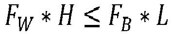
- Wherein:
- FW is the component of the weight force F of the work vehicle 1 acting on the center of gravity along W direction;
- FB is the component of the weight force F of the work vehicle 1 acting on the center of gravity along B axis direction;
- L is the distance between the point of application of force FB and a ground contact point of ground contact means 4; and
- H is the distance between the point of application of force FW and the ground.
- In view of the weight of the vehicle 1, that can be memorized or acquired via dedicated sensor means and the shape of the work vehicle, memorized into electronic unit, the gravity center, i.e. the weight force application point, can be easily determined.
- Then, in view of the inclination of the work vehicle 1, a critical distance L (i.e. a critical angle) can be determined. When such angle is overcome, electronic unit can calculate a distance X able to vary the center of gravity of work vehicle so as to modify the distance L and thereby satisfy the above mathematical condition.
- According to the above, the present invention clearly further refers to a method for avoiding the rollover of a work vehicle as defined above and comprising the following steps:
- Acquire data related to the position of the center of gravity of the work vehicle;
- Acquire data related to the inclination of the work vehicle 1 with respect to a vertical axis;
- Compare the acquired inclination angle with respect to a threshold angle;
- If the acquired inclination angle is lower with respect to the threshold angle, the actuator means 14 are not activated;
- If the acquired inclination angle is greater with respect to the threshold angle, the actuator means 14 are activated to modify the position of the
swivel ring assembly 8 with respect to the intermediate portion 7 of theundercarriage 2 along its width direction W of a quantity sufficient to avoid rollover of the work vehicle. - In particular, the center of gravity position may be calculated in function of the shape and the current weight of the work vehicle 1 or may be memorized as fixed value in the electronic unit.
- Furthermore, the threshold angle may be memorized in function of the typology of work vehicle 1 or can be calculated in function of the current center of gravity position of the vehicle.
- All the aforementioned steps of the above method may be memorized and executed by an electronic unit as defined in the preceding.
- In view of the foregoing, the advantages of work vehicle 1 provided with an anti-rollover system according to the invention are apparent.
- Thanks to the proposed
linear guide assembly 11 configured to allow the motion of the screwingassembly 8 along width direction W on the intermediate portion of theundercarriage 2, it is possible to vary the position of center of gravity of the work vehicle 1 thereby avoiding the rollover phenomenon. - Furthermore, since the undercarriage has a fixed width and only the screw-ring assembly moves with respect to its intermediate portion, the proposed system is robust and less sensible to dirty elements with respect to the one known in the prior art.
- Moreover, the proposed use of a recirculating spheres guide allows a minimal friction displacement of the screw ring assembly 1 with respect to
undercarriage 2, allowing a quick and inexpensive movement of allmain body 3 with simple, compact and cost-effective actuator means 14. - The use of actuator means 14 of hydraulic typology allows the integration of the latter with other hydraulic circuit of the work vehicle 1, thereby allowing a facilitated installation and control of the latter.
- The doubling of such actuator means 14, realized as
double acting cylinders 15, on both sides of rotation axis B with respect to screw ring assembly allows both a redundancy for safety reasons and the possibility of generating concurrent forces to move the screw-ring assembly 8. - It is clear that modifications can be made to the described work vehicle 1 provided with an anti-rollover system which do not extend beyond the scope of protection defined by the claims.
- For example, it is clear that actuator means 14 may be electromechanical means and that the number and disposition of such actuator means 14 to vary the position of the screw-ring assembly may be varied according to the typology of work vehicle 1.
- Furthermore, it is clear that the control strategy of the actuator means 14 may be varied accordingly the different use condition of the work vehicle.
- Clearly, the exemplarily shapes and number of the elements described and shown in the figures according to the typology of work vehicle 1.
Claims (15)
- Work vehicle (1) comprising an undercarriage (2) movable with respect to the ground thanks to ground contact means (4) and a main body (3) carried in a movable manner by said undercarriage (2),
said undercarriage comprising a pair of side members (6) and an intermediate portion (7) connecting said side members (6), said side members (6) being equally spaced along a width direction (W) with respect to a longitudinal plane (A) of said work vehicle (1),
said work vehicle (1) comprising a screw-ring assembly (8) configured to allow a rotation of said main body (3) with respect to said undercarriage (2) about an axis (B),
said work vehicle (1) comprising a linear guide assembly (11) axially interposed between said screw-ring assembly (8) and said intermediate portion (7) of said undercarriage and actuator means (14) configured to exert a force directed to said screw-ring assembly (8) so that said screw-ring assembly (8) is carried in a linear movable manner with respect to said undercarriage (2) along said width direction (W) in order to vary the location of said axis (B) with respect to said plane (A) along the width direction (W). - Work vehicle according to claim 1, wherein said linear guide assembly (11) comprises at least a guide (12) and a corresponding cart (13),
said guide (12) being fixedly carried by said intermediate portion (7) and defining a linear path along said width direction (W)
said cart (13) being fixedly carried by a lower portion (8a) of said screw-ring assembly (8) and configured to move along said guide (12). - Work vehicle according to claim 2, wherein said cart (13) is coupled to the respective guide (12) via a recirculating sphere system.
- Work vehicle according to claim 2 or 3, comprising a plurality of guides (12) and corresponding carts (13), said carts (13) being housed and fixed in corresponding seats (9) realized in said lower portion (8a) of said screw-ring assembly (8).
- Work vehicle according to any of claims 2 to 4, wherein said actuator means (14) exert their force on said cart (13).
- Work vehicle according to any of claims 2 to 5, wherein said actuator means (14) comprises hydraulic actuator means.
- Work vehicle according to any of claims 2 to 6, wherein said actuator means (14) comprises double action hydraulic cylinder (15).
- Work vehicle according to claim 7, wherein said double action hydraulic cylinder (15) comprises a plurality of stems (15b) acting on a single cart (13).
- Work vehicle according to any of the preceding claims, comprising actuator means (14) on both sides of said screw-ring assembly (8) with respect to said longitudinal plane (A).
- Work vehicle according to any of the preceding claims comprising sensor means (16) configured to detect data related to an inclination of said work vehicle (1) with respect to a vertical axis and an electronic unit comprising elaboration means configured to acquire said inclination data, elaborate the latter and control said actuator means (14) on the base of such elaboration inclination data.
- Work vehicle according to claim 10 comprising sensor means configured to detect data related to the weight of said work vehicle (1) said electronic unit being configured to elaborate the position of the center of gravity of said work vehicle (1) in function of a memorized shape of said work vehicle (1) and said data related to its weight.
- Method for avoiding the rollover of a work vehicle(1) according to claim 10 or 11 comprising the following steps:• Acquire data related to the position of the center of gravity of sais work vehicle (1);• Acquire data related to the inclination of said work vehicle (1) with respect to a vertical axis;• Compare the acquired inclination angle with respect to a threshold angle;• If the acquired inclination angle is lower with respect to the threshold angle, the actuator means (14) are not activated;• If the acquired inclination angle is greater with respect to the threshold angle, the actuator means (14) are controlled by said electronic unit to modify the position of said swivel ring assembly (8) with respect to said intermediate portion (7) of said undercarriage (2) along its width direction (W) of a quantity sufficient to avoid rollover of said work vehicle (1).
- Method according to claim 12, wherein said center of gravity position is memorized as fixed value in the electronic unit.
- Method according to claim 12 when depending on claim 11, wherein said center of gravity position is elaborated in function of a memorized shape of said work vehicle (1) and said data related to its weight.
- Method according to claims 12 to 14 wherein said threshold angle is memorized in said electronic unit or is calculated in function of the current center of gravity position of the vehicle.
Applications Claiming Priority (1)
| Application Number | Priority Date | Filing Date | Title |
|---|---|---|---|
| IT102020000014374A IT202000014374A1 (en) | 2020-06-16 | 2020-06-16 | WORK VEHICLE EQUIPPED WITH AN ANTI-ROLLOVER SYSTEM |
Publications (2)
| Publication Number | Publication Date |
|---|---|
| EP3926102A1 true EP3926102A1 (en) | 2021-12-22 |
| EP3926102B1 EP3926102B1 (en) | 2025-08-06 |
Family
ID=72179102
Family Applications (1)
| Application Number | Title | Priority Date | Filing Date |
|---|---|---|---|
| EP21179683.4A Active EP3926102B1 (en) | 2020-06-16 | 2021-06-16 | Work vehicle provided with an antirollover system |
Country Status (2)
| Country | Link |
|---|---|
| EP (1) | EP3926102B1 (en) |
| IT (1) | IT202000014374A1 (en) |
Citations (8)
| Publication number | Priority date | Publication date | Assignee | Title |
|---|---|---|---|---|
| LU37001A1 (en) * | 1958-03-25 | 1959-05-14 | Rabot Ets | Improvements to lifting equipment, particularly lifting equipment operating as excavator devices |
| US3160284A (en) * | 1963-02-01 | 1964-12-08 | Beloit Corp | Weight stabilizing load handling machine |
| US4679803A (en) * | 1986-01-27 | 1987-07-14 | The United States Of America As Represented By The Secretary Of Agriculture | Apparatus for maintaining stability of mobile land vehicles on sloping terrain |
| DE9319382U1 (en) | 1993-12-16 | 1995-04-13 | Sennebogen, Erich, 94315 Straubing | Chassis, in particular for a machine exposed to a tipping moment |
| ITAN20120027A1 (en) * | 2012-03-22 | 2013-09-23 | Massimiliano Savoretti | AGRICULTURAL MACHINE FOR LANDS IN SLOPE. |
| US20170089797A1 (en) * | 2015-09-30 | 2017-03-30 | Deere & Company | Stability warning and control intervention system for a forestry vehicle |
| EP3345858A1 (en) * | 2017-01-10 | 2018-07-11 | Tadano Mantis Corporation | Asymmetrical track crawler positioning system |
| US20190359267A1 (en) | 2017-02-16 | 2019-11-28 | Sumitomo Heavy Industries Construction Cranes Co., Ltd. | Working machine with crawler |
-
2020
- 2020-06-16 IT IT102020000014374A patent/IT202000014374A1/en unknown
-
2021
- 2021-06-16 EP EP21179683.4A patent/EP3926102B1/en active Active
Patent Citations (8)
| Publication number | Priority date | Publication date | Assignee | Title |
|---|---|---|---|---|
| LU37001A1 (en) * | 1958-03-25 | 1959-05-14 | Rabot Ets | Improvements to lifting equipment, particularly lifting equipment operating as excavator devices |
| US3160284A (en) * | 1963-02-01 | 1964-12-08 | Beloit Corp | Weight stabilizing load handling machine |
| US4679803A (en) * | 1986-01-27 | 1987-07-14 | The United States Of America As Represented By The Secretary Of Agriculture | Apparatus for maintaining stability of mobile land vehicles on sloping terrain |
| DE9319382U1 (en) | 1993-12-16 | 1995-04-13 | Sennebogen, Erich, 94315 Straubing | Chassis, in particular for a machine exposed to a tipping moment |
| ITAN20120027A1 (en) * | 2012-03-22 | 2013-09-23 | Massimiliano Savoretti | AGRICULTURAL MACHINE FOR LANDS IN SLOPE. |
| US20170089797A1 (en) * | 2015-09-30 | 2017-03-30 | Deere & Company | Stability warning and control intervention system for a forestry vehicle |
| EP3345858A1 (en) * | 2017-01-10 | 2018-07-11 | Tadano Mantis Corporation | Asymmetrical track crawler positioning system |
| US20190359267A1 (en) | 2017-02-16 | 2019-11-28 | Sumitomo Heavy Industries Construction Cranes Co., Ltd. | Working machine with crawler |
Also Published As
| Publication number | Publication date |
|---|---|
| EP3926102B1 (en) | 2025-08-06 |
| IT202000014374A1 (en) | 2021-12-16 |
Similar Documents
| Publication | Publication Date | Title |
|---|---|---|
| CN1781748B (en) | Vehicle suspension system | |
| EP2558312B1 (en) | Regulating device, railway wheel device, working machine as well as a method for driving of a rubber wheeled working machine along a railway track | |
| US10669131B2 (en) | Construction machine equipped with boom | |
| GB2295364A (en) | Electro-hydraulic steering system for an articulated vehicle | |
| US11686064B2 (en) | Skid-steer loader implement | |
| US10919417B2 (en) | Vehicle seat comprising mutually adjustable switching consoles | |
| JP2008049851A (en) | Vehicle toe angle variable control device | |
| EP3926102B1 (en) | Work vehicle provided with an antirollover system | |
| EP3383790A1 (en) | Support roller, vehicle with a support roller and method for stabilizing a vehicle | |
| JP6763712B2 (en) | Road-rail work vehicle | |
| US5125467A (en) | Telecontrolled tracked vehicle | |
| CA2983899C (en) | Track tensioner | |
| EP0040105A1 (en) | Safety device for banking vehicles | |
| EP0554723A1 (en) | Rear wheel steering device | |
| CA1272376A (en) | Improved running gear suspension for articulated construction vehicles | |
| US11327519B2 (en) | Control lever with sliding guide | |
| EP4130386B1 (en) | Shiftable cabin | |
| EP0940274B1 (en) | Device for the variation of the weight distribution on the supports of self-propelled operating machines | |
| CN112744250B (en) | Wheelset control system for hydraulic machinery used in rail vehicles | |
| US3504933A (en) | Vehicle counterweight | |
| US7494131B2 (en) | Assembly for a chassis stabilizing system | |
| US20040249537A1 (en) | Machine tool and method for operating machine tool | |
| CA2747032A1 (en) | Lock apparatus for variable gauge undercarriage | |
| US10036140B2 (en) | Track assembly of machine | |
| JPS5912487B2 (en) | Mortar Gradano Leaning Condition |
Legal Events
| Date | Code | Title | Description |
|---|---|---|---|
| PUAI | Public reference made under article 153(3) epc to a published international application that has entered the european phase |
Free format text: ORIGINAL CODE: 0009012 |
|
| STAA | Information on the status of an ep patent application or granted ep patent |
Free format text: STATUS: THE APPLICATION HAS BEEN PUBLISHED |
|
| AK | Designated contracting states |
Kind code of ref document: A1 Designated state(s): AL AT BE BG CH CY CZ DE DK EE ES FI FR GB GR HR HU IE IS IT LI LT LU LV MC MK MT NL NO PL PT RO RS SE SI SK SM TR |
|
| B565 | Issuance of search results under rule 164(2) epc |
Effective date: 20210805 |
|
| STAA | Information on the status of an ep patent application or granted ep patent |
Free format text: STATUS: REQUEST FOR EXAMINATION WAS MADE |
|
| 17P | Request for examination filed |
Effective date: 20220622 |
|
| RBV | Designated contracting states (corrected) |
Designated state(s): AL AT BE BG CH CY CZ DE DK EE ES FI FR GB GR HR HU IE IS IT LI LT LU LV MC MK MT NL NO PL PT RO RS SE SI SK SM TR |
|
| RAP3 | Party data changed (applicant data changed or rights of an application transferred) |
Owner name: CNH INDUSTRIAL ITALIA S.P.A. |
|
| STAA | Information on the status of an ep patent application or granted ep patent |
Free format text: STATUS: EXAMINATION IS IN PROGRESS |
|
| 17Q | First examination report despatched |
Effective date: 20240517 |
|
| GRAP | Despatch of communication of intention to grant a patent |
Free format text: ORIGINAL CODE: EPIDOSNIGR1 |
|
| STAA | Information on the status of an ep patent application or granted ep patent |
Free format text: STATUS: GRANT OF PATENT IS INTENDED |
|
| RIC1 | Information provided on ipc code assigned before grant |
Ipc: B62D 55/116 20060101ALI20250211BHEP Ipc: B62D 49/08 20060101ALI20250211BHEP Ipc: E02F 9/12 20060101ALI20250211BHEP Ipc: E02F 9/10 20060101ALI20250211BHEP Ipc: E02F 3/36 20060101AFI20250211BHEP |
|
| INTG | Intention to grant announced |
Effective date: 20250224 |
|
| GRAS | Grant fee paid |
Free format text: ORIGINAL CODE: EPIDOSNIGR3 |
|
| GRAA | (expected) grant |
Free format text: ORIGINAL CODE: 0009210 |
|
| STAA | Information on the status of an ep patent application or granted ep patent |
Free format text: STATUS: THE PATENT HAS BEEN GRANTED |
|
| AK | Designated contracting states |
Kind code of ref document: B1 Designated state(s): AL AT BE BG CH CY CZ DE DK EE ES FI FR GB GR HR HU IE IS IT LI LT LU LV MC MK MT NL NO PL PT RO RS SE SI SK SM TR |
|
| REG | Reference to a national code |
Ref country code: GB Ref legal event code: FG4D |
|
| REG | Reference to a national code |
Ref country code: CH Ref legal event code: EP |
|
| REG | Reference to a national code |
Ref country code: DE Ref legal event code: R096 Ref document number: 602021035450 Country of ref document: DE |
|
| REG | Reference to a national code |
Ref country code: IE Ref legal event code: FG4D |
|
| REG | Reference to a national code |
Ref country code: NL Ref legal event code: MP Effective date: 20250806 |
|
| PG25 | Lapsed in a contracting state [announced via postgrant information from national office to epo] |
Ref country code: IS Free format text: LAPSE BECAUSE OF FAILURE TO SUBMIT A TRANSLATION OF THE DESCRIPTION OR TO PAY THE FEE WITHIN THE PRESCRIBED TIME-LIMIT Effective date: 20251206 |
|
| PG25 | Lapsed in a contracting state [announced via postgrant information from national office to epo] |
Ref country code: NO Free format text: LAPSE BECAUSE OF FAILURE TO SUBMIT A TRANSLATION OF THE DESCRIPTION OR TO PAY THE FEE WITHIN THE PRESCRIBED TIME-LIMIT Effective date: 20251106 |
|
| REG | Reference to a national code |
Ref country code: LT Ref legal event code: MG9D |
|
| PG25 | Lapsed in a contracting state [announced via postgrant information from national office to epo] |
Ref country code: PT Free format text: LAPSE BECAUSE OF FAILURE TO SUBMIT A TRANSLATION OF THE DESCRIPTION OR TO PAY THE FEE WITHIN THE PRESCRIBED TIME-LIMIT Effective date: 20251209 |
|
| PG25 | Lapsed in a contracting state [announced via postgrant information from national office to epo] |
Ref country code: FI Free format text: LAPSE BECAUSE OF FAILURE TO SUBMIT A TRANSLATION OF THE DESCRIPTION OR TO PAY THE FEE WITHIN THE PRESCRIBED TIME-LIMIT Effective date: 20250806 |
|
| PG25 | Lapsed in a contracting state [announced via postgrant information from national office to epo] |
Ref country code: HR Free format text: LAPSE BECAUSE OF FAILURE TO SUBMIT A TRANSLATION OF THE DESCRIPTION OR TO PAY THE FEE WITHIN THE PRESCRIBED TIME-LIMIT Effective date: 20250806 Ref country code: NL Free format text: LAPSE BECAUSE OF FAILURE TO SUBMIT A TRANSLATION OF THE DESCRIPTION OR TO PAY THE FEE WITHIN THE PRESCRIBED TIME-LIMIT Effective date: 20250806 |
|
| PG25 | Lapsed in a contracting state [announced via postgrant information from national office to epo] |
Ref country code: GR Free format text: LAPSE BECAUSE OF FAILURE TO SUBMIT A TRANSLATION OF THE DESCRIPTION OR TO PAY THE FEE WITHIN THE PRESCRIBED TIME-LIMIT Effective date: 20251107 |
|
| PG25 | Lapsed in a contracting state [announced via postgrant information from national office to epo] |
Ref country code: SE Free format text: LAPSE BECAUSE OF FAILURE TO SUBMIT A TRANSLATION OF THE DESCRIPTION OR TO PAY THE FEE WITHIN THE PRESCRIBED TIME-LIMIT Effective date: 20250806 |
|
| PG25 | Lapsed in a contracting state [announced via postgrant information from national office to epo] |
Ref country code: LV Free format text: LAPSE BECAUSE OF FAILURE TO SUBMIT A TRANSLATION OF THE DESCRIPTION OR TO PAY THE FEE WITHIN THE PRESCRIBED TIME-LIMIT Effective date: 20250806 |
|
| PG25 | Lapsed in a contracting state [announced via postgrant information from national office to epo] |
Ref country code: PL Free format text: LAPSE BECAUSE OF FAILURE TO SUBMIT A TRANSLATION OF THE DESCRIPTION OR TO PAY THE FEE WITHIN THE PRESCRIBED TIME-LIMIT Effective date: 20250806 Ref country code: BG Free format text: LAPSE BECAUSE OF FAILURE TO SUBMIT A TRANSLATION OF THE DESCRIPTION OR TO PAY THE FEE WITHIN THE PRESCRIBED TIME-LIMIT Effective date: 20250806 |
|
| PG25 | Lapsed in a contracting state [announced via postgrant information from national office to epo] |
Ref country code: RS Free format text: LAPSE BECAUSE OF FAILURE TO SUBMIT A TRANSLATION OF THE DESCRIPTION OR TO PAY THE FEE WITHIN THE PRESCRIBED TIME-LIMIT Effective date: 20251106 |
|
| PG25 | Lapsed in a contracting state [announced via postgrant information from national office to epo] |
Ref country code: ES Free format text: LAPSE BECAUSE OF FAILURE TO SUBMIT A TRANSLATION OF THE DESCRIPTION OR TO PAY THE FEE WITHIN THE PRESCRIBED TIME-LIMIT Effective date: 20250806 |
|
| REG | Reference to a national code |
Ref country code: AT Ref legal event code: MK05 Ref document number: 1821975 Country of ref document: AT Kind code of ref document: T Effective date: 20250806 |
|
| PG25 | Lapsed in a contracting state [announced via postgrant information from national office to epo] |
Ref country code: SM Free format text: LAPSE BECAUSE OF FAILURE TO SUBMIT A TRANSLATION OF THE DESCRIPTION OR TO PAY THE FEE WITHIN THE PRESCRIBED TIME-LIMIT Effective date: 20250806 |
|
| PG25 | Lapsed in a contracting state [announced via postgrant information from national office to epo] |
Ref country code: DK Free format text: LAPSE BECAUSE OF FAILURE TO SUBMIT A TRANSLATION OF THE DESCRIPTION OR TO PAY THE FEE WITHIN THE PRESCRIBED TIME-LIMIT Effective date: 20250806 |
|
| PG25 | Lapsed in a contracting state [announced via postgrant information from national office to epo] |
Ref country code: AT Free format text: LAPSE BECAUSE OF FAILURE TO SUBMIT A TRANSLATION OF THE DESCRIPTION OR TO PAY THE FEE WITHIN THE PRESCRIBED TIME-LIMIT Effective date: 20250806 |
|
| PG25 | Lapsed in a contracting state [announced via postgrant information from national office to epo] |
Ref country code: CZ Free format text: LAPSE BECAUSE OF FAILURE TO SUBMIT A TRANSLATION OF THE DESCRIPTION OR TO PAY THE FEE WITHIN THE PRESCRIBED TIME-LIMIT Effective date: 20250806 |
|
| PG25 | Lapsed in a contracting state [announced via postgrant information from national office to epo] |
Ref country code: EE Free format text: LAPSE BECAUSE OF FAILURE TO SUBMIT A TRANSLATION OF THE DESCRIPTION OR TO PAY THE FEE WITHIN THE PRESCRIBED TIME-LIMIT Effective date: 20250806 Ref country code: SK Free format text: LAPSE BECAUSE OF FAILURE TO SUBMIT A TRANSLATION OF THE DESCRIPTION OR TO PAY THE FEE WITHIN THE PRESCRIBED TIME-LIMIT Effective date: 20250806 |
|
| REG | Reference to a national code |
Ref country code: DE Ref legal event code: R097 Ref document number: 602021035450 Country of ref document: DE |
|
| PLBE | No opposition filed within time limit |
Free format text: ORIGINAL CODE: 0009261 |
|
| STAA | Information on the status of an ep patent application or granted ep patent |
Free format text: STATUS: NO OPPOSITION FILED WITHIN TIME LIMIT |
|
| REG | Reference to a national code |
Ref country code: CH Ref legal event code: L10 Free format text: ST27 STATUS EVENT CODE: U-0-0-L10-L00 (AS PROVIDED BY THE NATIONAL OFFICE) Effective date: 20260617 |
|
| PG25 | Lapsed in a contracting state [announced via postgrant information from national office to epo] |
Ref country code: LT Free format text: LAPSE BECAUSE OF FAILURE TO SUBMIT A TRANSLATION OF THE DESCRIPTION OR TO PAY THE FEE WITHIN THE PRESCRIBED TIME-LIMIT Effective date: 20250806 |
|
| PGFP | Annual fee paid to national office [announced via postgrant information from national office to epo] |
Ref country code: GB Payment date: 20260622 Year of fee payment: 6 |
|
| PGFP | Annual fee paid to national office [announced via postgrant information from national office to epo] |
Ref country code: IT Payment date: 20260623 Year of fee payment: 6 |
|
| PGFP | Annual fee paid to national office [announced via postgrant information from national office to epo] |
Ref country code: DE Payment date: 20260623 Year of fee payment: 6 |
|
| 26N | No opposition filed |
Effective date: 20260507 |
|
| PGFP | Annual fee paid to national office [announced via postgrant information from national office to epo] |
Ref country code: FR Payment date: 20260622 Year of fee payment: 6 |