EP3926087A1 - Clothing care machine - Google Patents
Clothing care machine Download PDFInfo
- Publication number
- EP3926087A1 EP3926087A1 EP21174953.6A EP21174953A EP3926087A1 EP 3926087 A1 EP3926087 A1 EP 3926087A1 EP 21174953 A EP21174953 A EP 21174953A EP 3926087 A1 EP3926087 A1 EP 3926087A1
- Authority
- EP
- European Patent Office
- Prior art keywords
- cover body
- engaging member
- elastic positioning
- positioning portion
- clothing care
- Prior art date
- Legal status (The legal status is an assumption and is not a legal conclusion. Google has not performed a legal analysis and makes no representation as to the accuracy of the status listed.)
- Granted
Links
Images

Classifications
-
- D—TEXTILES; PAPER
- D06—TREATMENT OF TEXTILES OR THE LIKE; LAUNDERING; FLEXIBLE MATERIALS NOT OTHERWISE PROVIDED FOR
- D06F—LAUNDERING, DRYING, IRONING, PRESSING OR FOLDING TEXTILE ARTICLES
- D06F39/00—Details of washing machines not specific to a single type of machines covered by groups D06F9/00 - D06F27/00
- D06F39/12—Casings; Tubs
- D06F39/14—Doors or covers; Securing means therefor
Definitions
- the present invention relates to the field of household appliance technologies, and specifically, to a clothing care machine.
- a closure of an access port of a clothing care machine is generally fixed on a machine body with a fastener.
- the closure needs to be first removed with a tool, bringing a lot of inconvenience to maintenance personnel in operation. Therefore, a press-type locking structure, for example, a press-type door lock structure disclosed in US4657291A , is considered to be used on the closure of the access port.
- a press-type locking structure for example, a press-type door lock structure disclosed in US4657291A , is considered to be used on the closure of the access port.
- the cover body is prone to shaking due to lacking positioning support; even, noise is likely to be generated when a washing machine works.
- One of objectives of embodiments of the present invention is to provide a clothing care machine, and in particular, to effectively alleviate at least one of the above technical problems.
- An aspect of the embodiments of the present invention provides a clothing care machine, including a machine body and a closure assembly disposed on the machine body, the closure assembly being configured to open and close an access port, and characterized in that: the closure assembly includes: an engaging member fixedly connected to the machine body, where the engaging member includes a passage corresponding to the access port; a cover body connected to the engaging member through a rotating shaft, where a buckle is disposed on the cover body, a door lock engaged with the buckle is disposed on the engaging member, and the door lock is configured to lock or unlock the cover body through pressing of the buckle; and an elastic positioning portion, where the elastic positioning portion is disposed on at least one of the engaging member and the cover body; when the cover body is pressed, the elastic positioning portion is pushed and deformed to provide a displacement distance required by the buckle for pressing the door lock; and when the cover body is locked, the elastic positioning portion abuts against the other one of the engaging member and the cover body.
- the elastic positioning portion provides a stable supporting force to the cover body when a locking operation is performed and after the cover body is locked, thereby improving stability of the cover body after the door lock is locked.
- the at least two elastic positioning portions are symmetrically distributed relative to the door lock. This facilitates a uniform and stable supporting force for the cover body.
- one end of the elastic positioning portion is fixedly connected to one of the engaging member and the cover body, the other end is a free end, and when the cover body and the engaging member are locked, the free end is supported on the other one of the engaging member and the cover body.
- the elastic positioning portion is fixedly connected to the closure assembly, thereby improving support stability of the elastic positioning portion.
- the elastic positioning portion includes a fixing portion fixedly connected to the engaging member and a boom portion formed by extending from the fixing portion.
- the formation of the boom portion causes the elastic positioning portion to be pushed and deformed. Therefore, it is easier to satisfy requirements of a distance of pressing.
- the other one of the cover body and the engaging member is provided with a boss in contact with the boom portion when the cover body is locked.
- the boom portion is pressed by the boss, so that a thrust can be applied to the elastic positioning portion and the cover body can be easily positioned.
- the elastic positioning portion includes the fixing portion fixedly connected to the engaging member and the boom portion formed by extending from the fixing portion.
- the boss abuts against the boom portion, and an end of the boom portion is provided with a protrusion facing the boss.
- the protrusion can limit the boss when the boss applies a thrust.
- the boss on a side near a center of the machine body relative to the door lock is higher than the boss on the other side.
- the elastic positioning portion includes a spring or a rubber block.
- the elastic positioning portion and the engaging member or the cover body are manufactured integrally, facilitating manufacture and assembly of the elastic positioning portion and reducing material costs and process costs.
- the boss and the engaging member or the cover body are formed integrally, facilitating manufacture of the boss.
- the rotating shaft is located at the bottom of the access port. Because the rotating shaft is disposed at the bottom of the access port, after the cover body is pressed to unlock, the cover body automatically keeps the door open under actions of an elastic force of the door lock and a gravity of the cover body, requiring no additional operations performed by maintenance personnel.
- An access port of a clothing care machine of the present invention is provided with a closure assembly, and the closure assembly is in a press-type locking structure, so that maintenance personnel can conveniently and quickly open a cover body with one hand.
- an elastic positioning structure can satisfy requirements of a displacement distance of pressing of the press-type locking structure.
- the cover body is provided with a uniform and stable supporting force, so that the cover body is not prone to shaking. Therefore, when a clothing processing device works, the noise generated by shaking of a door can be reduced.
- a clothing care machine includes a machine body 1, a closure assembly 2 is disposed on a front panel 3 of the machine body 1, and the closure assembly 2 is configured to open and close an access port.
- the access port may be an access configured to perform overhauling or a specific operation on the clothing care machine.
- a closure and a sewage pipe of a draining pump, and/or a forcible door opening device, and/or an air inlet and a filter screen of a washing machine may be disposed inside the access port.
- the access port and the closure assembly 2 may be alternatively disposed as required at other positions of the machine body that are convenient for operations.
- the closure assembly 2 includes a cover body 4 and an engaging member 5, the cover body 4 is connected to the engaging member 5 through a rotating shaft 8, and the cover body 4 can be opened by being rotated about the rotating shaft 8.
- the engaging member 5 is provided with a passage corresponding to the access port, and is connected to the machine body 1 by a mechanical structure, for example, a fastener.
- the engaging member 5 may be further provided with a rotating shaft mounting base 9 engaged with the rotating shaft 8 to rotatably connect to the cover body 4.
- a buckle 7 is disposed on the cover body 4, and a door lock 6 engaged with the buckle 7 is disposed on the engaging member 5.
- the cover body 4 is pressed to enable the buckle 7 on the cover body 4 to push an elastic element in the door lock 6, to lock and unlock the door lock 6.
- An elastic positioning portion 10 is disposed on at least one of the engaging member 5 and the cover body 4, for example, on a surface of the cover body 4 facing the engaging member 5 and/or a surface of a flange of the engaging member 5 facing the cover body 4.
- the elastic positioning portion 10 When the cover body 4 is pressed, the elastic positioning portion 10 is pushed and deformed to provide a displacement distance required by the buckle 7 for pressing the door lock 6; and when the cover body 4 is locked, the elastic positioning portion 10 abuts against the other one of the engaging member 5 and the cover body 4. The cover body 4 is supported and positioned by the elastic positioning portion 10 to prevent the cover body 4 from shaking when being locked and after being locked.
- At least two elastic positioning portions 10 There may be at least two elastic positioning portions 10, and the at least two elastic positioning portions 10 are symmetrically distributed relative to the door lock. This facilitates a uniform and stable supporting force for the cover body 4.
- One end of the elastic positioning portion 10 may be fixedly connected to one of the engaging member 5 and the cover body 4, and the other end is a free end. When the cover body 4 and the engaging member 5 are locked, the free end may be supported on the other one of the engaging member 5 and the cover body 4.
- the elastic positioning portion 10 may include a fixing portion 11 fixedly connected to the engaging member and a boom portion 12 formed by extending from the fixing portion 11.
- the formation of the boom portion 12 causes the elastic positioning portion 10 to be pushed and deformed. Therefore, it is easier to satisfy requirements of a distance of pressing.
- the other one of the cover body 4 and the engaging member 5 may be provided with a boss 14 abutting against the boom portion 12 when the cover body 4 is locked.
- a height of the boss may be designed according to a height of the front panel 3 relative to the engaging member. For example, in some specific cases, when the front panel 3 is curved and is fixedly connected to the engaging member 5 with a specific angle, the boss on a side near a center of the machine body 1 relative to the door lock 6 is higher than the boss on the other side, so that the cover body is flush with the front panel, and an appearance of the clothing care machine is aesthetic.
- the boss 14 When the cover body 4 is locked, the boss 14 abuts against the boom portion 12, and an end of the boom portion 12 is provided with a protrusion 15 facing the boss 14.
- the protrusion 15 can limit the boss 14 when the boss 14 applies a thrust.
- the elastic positioning portion 10 When the cover body is locked, the elastic positioning portion 10 is in contact with the boss 14 as a supporting structure, and meanwhile, the rotating shaft 8 and the door lock 6 are disposed to completely limit a degree of freedom of the cover body 4, to prevent the cover body 4 from shaking.
- the cover body When the cover body is unlocked, the cover body 4 is pressed, the elastic positioning portion 10 is deformed, and the elastic element in the door lock 6 is pressed by the buckle on the cover body 4. After a distance required by the thrust to unlock is satisfied, the door lock 6 is opened, and the cover body is opened by being rotated about the rotating shaft.
- the elastic positioning portion 10 may be made of the same material as that of the engaging member 5 or the cover body, and is integrally formed with the engaging member 5 or the cover body 4, thereby facilitating manufacture of the elastic positioning portion 10 and reducing costs.
- the elastic positioning portion 10 may be alternatively designed as a spring or a rubber block fixedly connected to the engaging member 5 or the cover body 4.
- the spring or the rubber block may be integrally manufactured with the engaging member 5 or the cover body 4 by using an insert injection molding method, or may be connected to the engaging member 5 or the cover body 4 by other means such as gluing.
- the rotating shaft 8 is disposed at the bottom of the access port. Because the rotating shaft 8 is disposed at the bottom of the access port, after the cover body 4 is pressed to unlock, the cover body 4 automatically keeps the door open under actions of an elastic force of the door lock 6 and a gravity of the cover body 4, requiring no additional operations performed by maintenance personnel.
Landscapes
- Engineering & Computer Science (AREA)
- Textile Engineering (AREA)
- Main Body Construction Of Washing Machines And Laundry Dryers (AREA)
- Casings For Electric Apparatus (AREA)
Abstract
Description
- The present invention relates to the field of household appliance technologies, and specifically, to a clothing care machine.
- At present, a closure of an access port of a clothing care machine is generally fixed on a machine body with a fastener. During overhauling, the closure needs to be first removed with a tool, bringing a lot of inconvenience to maintenance personnel in operation. Therefore, a press-type locking structure, for example, a press-type door lock structure disclosed in
US4657291A , is considered to be used on the closure of the access port. However, when the press-type locking structure is used and after a cover body is locked, the cover body is prone to shaking due to lacking positioning support; even, noise is likely to be generated when a washing machine works. - One of objectives of embodiments of the present invention is to provide a clothing care machine, and in particular, to effectively alleviate at least one of the above technical problems.
- An aspect of the embodiments of the present invention provides a clothing care machine, including a machine body and a closure assembly disposed on the machine body, the closure assembly being configured to open and close an access port, and characterized in that:
the closure assembly includes: an engaging member fixedly connected to the machine body, where the engaging member includes a passage corresponding to the access port; a cover body connected to the engaging member through a rotating shaft, where a buckle is disposed on the cover body, a door lock engaged with the buckle is disposed on the engaging member, and the door lock is configured to lock or unlock the cover body through pressing of the buckle; and an elastic positioning portion, where the elastic positioning portion is disposed on at least one of the engaging member and the cover body; when the cover body is pressed, the elastic positioning portion is pushed and deformed to provide a displacement distance required by the buckle for pressing the door lock; and when the cover body is locked, the elastic positioning portion abuts against the other one of the engaging member and the cover body. - The elastic positioning portion provides a stable supporting force to the cover body when a locking operation is performed and after the cover body is locked, thereby improving stability of the cover body after the door lock is locked.
- Optionally, there are at least two elastic positioning portions, and the at least two elastic positioning portions are symmetrically distributed relative to the door lock. This facilitates a uniform and stable supporting force for the cover body.
- Optionally, one end of the elastic positioning portion is fixedly connected to one of the engaging member and the cover body, the other end is a free end, and when the cover body and the engaging member are locked, the free end is supported on the other one of the engaging member and the cover body. The elastic positioning portion is fixedly connected to the closure assembly, thereby improving support stability of the elastic positioning portion.
- Optionally, the elastic positioning portion includes a fixing portion fixedly connected to the engaging member and a boom portion formed by extending from the fixing portion. The formation of the boom portion causes the elastic positioning portion to be pushed and deformed. Therefore, it is easier to satisfy requirements of a distance of pressing.
- Optionally, the other one of the cover body and the engaging member is provided with a boss in contact with the boom portion when the cover body is locked. The boom portion is pressed by the boss, so that a thrust can be applied to the elastic positioning portion and the cover body can be easily positioned.
- Optionally, the elastic positioning portion includes the fixing portion fixedly connected to the engaging member and the boom portion formed by extending from the fixing portion. When the cover body is locked, the boss abuts against the boom portion, and an end of the boom portion is provided with a protrusion facing the boss. The protrusion can limit the boss when the boss applies a thrust.
- Optionally, the boss on a side near a center of the machine body relative to the door lock is higher than the boss on the other side.
- Optionally, the elastic positioning portion includes a spring or a rubber block.
- Optionally, the elastic positioning portion and the engaging member or the cover body are manufactured integrally, facilitating manufacture and assembly of the elastic positioning portion and reducing material costs and process costs.
- Optionally, the boss and the engaging member or the cover body are formed integrally, facilitating manufacture of the boss.
- Optionally, the rotating shaft is located at the bottom of the access port. Because the rotating shaft is disposed at the bottom of the access port, after the cover body is pressed to unlock, the cover body automatically keeps the door open under actions of an elastic force of the door lock and a gravity of the cover body, requiring no additional operations performed by maintenance personnel.
- Compared to the prior art, the technical solutions of the embodiments of the present invention have the following advantages. An access port of a clothing care machine of the present invention is provided with a closure assembly, and the closure assembly is in a press-type locking structure, so that maintenance personnel can conveniently and quickly open a cover body with one hand. Meanwhile, compared with a rigid positioning structure, an elastic positioning structure can satisfy requirements of a displacement distance of pressing of the press-type locking structure. In addition, when a locking operation is performed and after the cover body is locked, the cover body is provided with a uniform and stable supporting force, so that the cover body is not prone to shaking. Therefore, when a clothing processing device works, the noise generated by shaking of a door can be reduced.
-
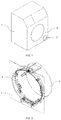
FIG. 1 is a schematic structural diagram of a clothing care machine according to an embodiment of the present invention; -
FIG. 2 is a schematic structural diagram when a closure assembly is closed according to an embodiment of the present invention; and -
FIG. 3 is a schematic structural diagram when a closure assembly is opened according to an embodiment of the present invention. - To make the above objectives, features and advantages of the present invention more obvious and comprehensible, specific embodiments of the present invention will be explained in detail below with reference to the accompanying drawings, but not intended to limit the scope of the present invention.
- As shown in
FIG. 1 to FIG. 3 , in this embodiment, a clothing care machine includes amachine body 1, aclosure assembly 2 is disposed on afront panel 3 of themachine body 1, and theclosure assembly 2 is configured to open and close an access port. The access port may be an access configured to perform overhauling or a specific operation on the clothing care machine. For example, a closure and a sewage pipe of a draining pump, and/or a forcible door opening device, and/or an air inlet and a filter screen of a washing machine may be disposed inside the access port. The access port and theclosure assembly 2 may be alternatively disposed as required at other positions of the machine body that are convenient for operations. - In this embodiment, the
closure assembly 2 includes acover body 4 and anengaging member 5, thecover body 4 is connected to theengaging member 5 through a rotatingshaft 8, and thecover body 4 can be opened by being rotated about the rotatingshaft 8. Theengaging member 5 is provided with a passage corresponding to the access port, and is connected to themachine body 1 by a mechanical structure, for example, a fastener. Theengaging member 5 may be further provided with a rotatingshaft mounting base 9 engaged with the rotatingshaft 8 to rotatably connect to thecover body 4. - A
buckle 7 is disposed on thecover body 4, and adoor lock 6 engaged with thebuckle 7 is disposed on theengaging member 5. Thecover body 4 is pressed to enable thebuckle 7 on thecover body 4 to push an elastic element in thedoor lock 6, to lock and unlock thedoor lock 6. - An
elastic positioning portion 10 is disposed on at least one of theengaging member 5 and thecover body 4, for example, on a surface of thecover body 4 facing theengaging member 5 and/or a surface of a flange of theengaging member 5 facing thecover body 4. - When the
cover body 4 is pressed, theelastic positioning portion 10 is pushed and deformed to provide a displacement distance required by thebuckle 7 for pressing thedoor lock 6; and when thecover body 4 is locked, theelastic positioning portion 10 abuts against the other one of theengaging member 5 and thecover body 4. Thecover body 4 is supported and positioned by theelastic positioning portion 10 to prevent thecover body 4 from shaking when being locked and after being locked. - There may be at least two
elastic positioning portions 10, and the at least twoelastic positioning portions 10 are symmetrically distributed relative to the door lock. This facilitates a uniform and stable supporting force for thecover body 4. - One end of the
elastic positioning portion 10 may be fixedly connected to one of theengaging member 5 and thecover body 4, and the other end is a free end. When thecover body 4 and theengaging member 5 are locked, the free end may be supported on the other one of theengaging member 5 and thecover body 4. - The
elastic positioning portion 10 may include afixing portion 11 fixedly connected to the engaging member and aboom portion 12 formed by extending from thefixing portion 11. The formation of theboom portion 12 causes theelastic positioning portion 10 to be pushed and deformed. Therefore, it is easier to satisfy requirements of a distance of pressing. - The other one of the
cover body 4 and theengaging member 5 may be provided with aboss 14 abutting against theboom portion 12 when thecover body 4 is locked. A height of the boss may be designed according to a height of thefront panel 3 relative to the engaging member. For example, in some specific cases, when thefront panel 3 is curved and is fixedly connected to theengaging member 5 with a specific angle, the boss on a side near a center of themachine body 1 relative to thedoor lock 6 is higher than the boss on the other side, so that the cover body is flush with the front panel, and an appearance of the clothing care machine is aesthetic. - When the
cover body 4 is locked, theboss 14 abuts against theboom portion 12, and an end of theboom portion 12 is provided with aprotrusion 15 facing theboss 14. Theprotrusion 15 can limit theboss 14 when theboss 14 applies a thrust. - When the cover body is locked, the
elastic positioning portion 10 is in contact with theboss 14 as a supporting structure, and meanwhile, therotating shaft 8 and thedoor lock 6 are disposed to completely limit a degree of freedom of thecover body 4, to prevent thecover body 4 from shaking. - When the cover body is unlocked, the
cover body 4 is pressed, theelastic positioning portion 10 is deformed, and the elastic element in thedoor lock 6 is pressed by the buckle on thecover body 4. After a distance required by the thrust to unlock is satisfied, thedoor lock 6 is opened, and the cover body is opened by being rotated about the rotating shaft. - The
elastic positioning portion 10 may be made of the same material as that of theengaging member 5 or the cover body, and is integrally formed with theengaging member 5 or thecover body 4, thereby facilitating manufacture of theelastic positioning portion 10 and reducing costs. - Certainly, the
elastic positioning portion 10 may be alternatively designed as a spring or a rubber block fixedly connected to theengaging member 5 or thecover body 4. The spring or the rubber block may be integrally manufactured with the engagingmember 5 or thecover body 4 by using an insert injection molding method, or may be connected to the engagingmember 5 or thecover body 4 by other means such as gluing. - Preferentially, the
rotating shaft 8 is disposed at the bottom of the access port. Because therotating shaft 8 is disposed at the bottom of the access port, after thecover body 4 is pressed to unlock, thecover body 4 automatically keeps the door open under actions of an elastic force of thedoor lock 6 and a gravity of thecover body 4, requiring no additional operations performed by maintenance personnel. - At this point, it should be recognized by those skilled in the art that, although a plurality of exemplary embodiments of the present invention have been exhaustively shown and described herein, many other variations or modifications consistent with the principles of the present invention can still be directly determined or deduced from the disclosure of the present invention without departing from the spirit and scope of the present invention. Therefore, the scope of the present invention should be understood and held to cover all such other variations or modifications.
Claims (10)
- A clothing care machine, comprising a machine body (1) and a closure assembly (2) disposed on the machine body (1), the closure assembly (2) being configured to open and close an access port, characterized in that
the closure assembly (2) comprises: an engaging member (5) fixedly connected to the machine body (1), wherein the engaging member (5) comprises a passage (13) corresponding to the access port;
a cover body (4) connected to the engaging member (5) through a rotating shaft (8), wherein a buckle (7) is disposed on the cover body (4), a door lock (6) engaged with the buckle (7) is disposed on the engaging member (5), and the door lock (6) is configured to lock or unlock the cover body (4) through pressing of the buckle (7); and
an elastic positioning portion (10), wherein the elastic positioning portion (10) is disposed on at least one of the engaging member (5) and the cover body (4); when the cover body (4) is pressed, the elastic positioning portion (10) is pushed and deformed to provide a displacement distance required by the buckle (7) for pressing the door lock (6); and when the cover body (4) is locked, the elastic positioning portion (10) abuts against the other one of the engaging member (5) and the cover body (4). - The clothing care machine according to claim 1, characterized in that there are at least two elastic positioning portions (10), and the at least two elastic positioning portions (10) are symmetrically distributed relative to the door lock (6).
- The clothing care machine according to claim 1, characterized in that one end of the elastic positioning portion (10) is fixedly connected to one of the engaging member (5) and the cover body (4), the other end is a free end, and when the cover body (4) and the engaging member (5) are locked, the free end is supported on the other one of the engaging member (5) and the cover body (4).
- The clothing care machine according to claim 1, characterized in that the elastic positioning portion (10) comprises a fixing portion (11) fixedly connected to the engaging member (5) and a boom portion (12) formed by extending from the fixing portion (11).
- The clothing care machine according to claim 4, characterized in that the other one of the cover body (4) and the engaging member (5) is provided with a boss (14) in contact with the boom portion (12) when the cover body (4) is locked.
- The clothing care machine according to claim 5, characterized in that when the cover body (4) is locked, the boss (14) abuts against the boom portion (12), and one end of the boom portion (12) away from the fixing portion is provided with a protrusion (15) facing the boss (14).
- The clothing care machine according to claim 5, characterized in that the boss (14) on a side near a center of the machine body (1) relative to the door lock (6) is higher than the boss (14) on the other side.
- The clothing care machine according to claim 1, characterized in that the elastic positioning portion (10) comprises a spring or a rubber block.
- The clothing care machine according to claim 1, characterized in that the elastic positioning portion (10) and the engaging member (5) or the cover body (4) are manufactured integrally.
- The clothing care machine according to claim 6, characterized in that the boss (14) and the engaging member (5) or the cover body (4) are formed integrally.
Applications Claiming Priority (1)
| Application Number | Priority Date | Filing Date | Title |
|---|---|---|---|
| CN202021128831.4U CN213624849U (en) | 2020-06-17 | 2020-06-17 | Clothes nursing machine |
Publications (2)
| Publication Number | Publication Date |
|---|---|
| EP3926087A1 true EP3926087A1 (en) | 2021-12-22 |
| EP3926087B1 EP3926087B1 (en) | 2023-09-27 |
Family
ID=76034512
Family Applications (1)
| Application Number | Title | Priority Date | Filing Date |
|---|---|---|---|
| EP21174953.6A Active EP3926087B1 (en) | 2020-06-17 | 2021-05-20 | Clothing care machine |
Country Status (2)
| Country | Link |
|---|---|
| EP (1) | EP3926087B1 (en) |
| CN (1) | CN213624849U (en) |
Cited By (1)
| Publication number | Priority date | Publication date | Assignee | Title |
|---|---|---|---|---|
| CN114808408A (en) * | 2022-05-19 | 2022-07-29 | Tcl家用电器(合肥)有限公司 | Flip structure, thread scrap collecting device and clothes dryer |
Citations (4)
| Publication number | Priority date | Publication date | Assignee | Title |
|---|---|---|---|---|
| US4657291A (en) | 1985-04-24 | 1987-04-14 | Nifco, Inc. | Locking device |
| EP1967639A1 (en) * | 2007-03-08 | 2008-09-10 | Samsung Electronics Co., Ltd. | Washing machine with ornamental panel |
| CN204608440U (en) * | 2015-03-26 | 2015-09-02 | 无锡小天鹅股份有限公司 | For washing machine filter box assembly and there is its washing machine |
| CN109652958A (en) * | 2019-01-29 | 2019-04-19 | 青岛海尔滚筒洗衣机有限公司 | A kind of washing machine |
-
2020
- 2020-06-17 CN CN202021128831.4U patent/CN213624849U/en active Active
-
2021
- 2021-05-20 EP EP21174953.6A patent/EP3926087B1/en active Active
Patent Citations (4)
| Publication number | Priority date | Publication date | Assignee | Title |
|---|---|---|---|---|
| US4657291A (en) | 1985-04-24 | 1987-04-14 | Nifco, Inc. | Locking device |
| EP1967639A1 (en) * | 2007-03-08 | 2008-09-10 | Samsung Electronics Co., Ltd. | Washing machine with ornamental panel |
| CN204608440U (en) * | 2015-03-26 | 2015-09-02 | 无锡小天鹅股份有限公司 | For washing machine filter box assembly and there is its washing machine |
| CN109652958A (en) * | 2019-01-29 | 2019-04-19 | 青岛海尔滚筒洗衣机有限公司 | A kind of washing machine |
Cited By (2)
| Publication number | Priority date | Publication date | Assignee | Title |
|---|---|---|---|---|
| CN114808408A (en) * | 2022-05-19 | 2022-07-29 | Tcl家用电器(合肥)有限公司 | Flip structure, thread scrap collecting device and clothes dryer |
| CN114808408B (en) * | 2022-05-19 | 2024-04-30 | Tcl家用电器(合肥)有限公司 | A flip cover structure, a thread scrap collecting device and a clothes dryer |
Also Published As
| Publication number | Publication date |
|---|---|
| CN213624849U (en) | 2021-07-06 |
| EP3926087B1 (en) | 2023-09-27 |
Similar Documents
| Publication | Publication Date | Title |
|---|---|---|
| JPH01500206A (en) | furniture hinges | |
| EP3926087B1 (en) | Clothing care machine | |
| US6637785B2 (en) | Handle device | |
| EP2740830A1 (en) | Detergent case apparatus for washing machine | |
| CN101363185B (en) | Device for controlling cover-opening and electricity-shut-off chain of refrigerator | |
| KR20210009650A (en) | Washing machine | |
| CN116446729B (en) | Door assembly of cooking utensil and cooking utensil | |
| CN111485396A (en) | An observation window applied to a drum washing machine | |
| CN209482838U (en) | Plastic surface lock | |
| CN212773991U (en) | Portable door lock structure | |
| CN207537760U (en) | A kind of washing machine cover lock set and washing machine | |
| CN223853463U (en) | Draining and filtering device for water tank | |
| KR100476960B1 (en) | Cover locking device of washing machine | |
| KR20190016720A (en) | console arm-rest open and close structure | |
| CN211397004U (en) | Manual unlocking piece | |
| KR100452375B1 (en) | The top plate mounting spring holder of a drum washer | |
| CN223025831U (en) | Inner cup, lid subassembly and cooking utensil | |
| CN207601677U (en) | A kind of operating mechanism and cabinet | |
| KR100528956B1 (en) | Device for locking landing door for elevator | |
| CN215686735U (en) | Lid assembly and have its cooking utensil | |
| CN2744797Y (en) | Automatic handle lock for sliding door and window | |
| CN217256185U (en) | High-stability locking permanent machine elastic sheet, drawer with same and tool box | |
| CN222982876U (en) | Key assembly and cooking utensil with same | |
| JP2935202B2 (en) | Lid mounting structure | |
| JP3023192U (en) | Lock for trunks |
Legal Events
| Date | Code | Title | Description |
|---|---|---|---|
| PUAI | Public reference made under article 153(3) epc to a published international application that has entered the european phase |
Free format text: ORIGINAL CODE: 0009012 |
|
| STAA | Information on the status of an ep patent application or granted ep patent |
Free format text: STATUS: THE APPLICATION HAS BEEN PUBLISHED |
|
| AK | Designated contracting states |
Kind code of ref document: A1 Designated state(s): AL AT BE BG CH CY CZ DE DK EE ES FI FR GB GR HR HU IE IS IT LI LT LU LV MC MK MT NL NO PL PT RO RS SE SI SK SM TR |
|
| B565 | Issuance of search results under rule 164(2) epc |
Effective date: 20211111 |
|
| STAA | Information on the status of an ep patent application or granted ep patent |
Free format text: STATUS: REQUEST FOR EXAMINATION WAS MADE |
|
| 17P | Request for examination filed |
Effective date: 20220622 |
|
| RBV | Designated contracting states (corrected) |
Designated state(s): AL AT BE BG CH CY CZ DE DK EE ES FI FR GB GR HR HU IE IS IT LI LT LU LV MC MK MT NL NO PL PT RO RS SE SI SK SM TR |
|
| GRAP | Despatch of communication of intention to grant a patent |
Free format text: ORIGINAL CODE: EPIDOSNIGR1 |
|
| STAA | Information on the status of an ep patent application or granted ep patent |
Free format text: STATUS: GRANT OF PATENT IS INTENDED |
|
| INTG | Intention to grant announced |
Effective date: 20230522 |
|
| GRAS | Grant fee paid |
Free format text: ORIGINAL CODE: EPIDOSNIGR3 |
|
| GRAA | (expected) grant |
Free format text: ORIGINAL CODE: 0009210 |
|
| STAA | Information on the status of an ep patent application or granted ep patent |
Free format text: STATUS: THE PATENT HAS BEEN GRANTED |
|
| AK | Designated contracting states |
Kind code of ref document: B1 Designated state(s): AL AT BE BG CH CY CZ DE DK EE ES FI FR GB GR HR HU IE IS IT LI LT LU LV MC MK MT NL NO PL PT RO RS SE SI SK SM TR |
|
| REG | Reference to a national code |
Ref country code: GB Ref legal event code: FG4D |
|
| REG | Reference to a national code |
Ref country code: CH Ref legal event code: EP |
|
| REG | Reference to a national code |
Ref country code: DE Ref legal event code: R096 Ref document number: 602021005376 Country of ref document: DE |
|
| REG | Reference to a national code |
Ref country code: IE Ref legal event code: FG4D |
|
| REG | Reference to a national code |
Ref country code: LT Ref legal event code: MG9D |
|
| PG25 | Lapsed in a contracting state [announced via postgrant information from national office to epo] |
Ref country code: GR Free format text: LAPSE BECAUSE OF FAILURE TO SUBMIT A TRANSLATION OF THE DESCRIPTION OR TO PAY THE FEE WITHIN THE PRESCRIBED TIME-LIMIT Effective date: 20231228 |
|
| PG25 | Lapsed in a contracting state [announced via postgrant information from national office to epo] |
Ref country code: SE Free format text: LAPSE BECAUSE OF FAILURE TO SUBMIT A TRANSLATION OF THE DESCRIPTION OR TO PAY THE FEE WITHIN THE PRESCRIBED TIME-LIMIT Effective date: 20230927 Ref country code: RS Free format text: LAPSE BECAUSE OF FAILURE TO SUBMIT A TRANSLATION OF THE DESCRIPTION OR TO PAY THE FEE WITHIN THE PRESCRIBED TIME-LIMIT Effective date: 20230927 Ref country code: NO Free format text: LAPSE BECAUSE OF FAILURE TO SUBMIT A TRANSLATION OF THE DESCRIPTION OR TO PAY THE FEE WITHIN THE PRESCRIBED TIME-LIMIT Effective date: 20231227 Ref country code: LV Free format text: LAPSE BECAUSE OF FAILURE TO SUBMIT A TRANSLATION OF THE DESCRIPTION OR TO PAY THE FEE WITHIN THE PRESCRIBED TIME-LIMIT Effective date: 20230927 Ref country code: LT Free format text: LAPSE BECAUSE OF FAILURE TO SUBMIT A TRANSLATION OF THE DESCRIPTION OR TO PAY THE FEE WITHIN THE PRESCRIBED TIME-LIMIT Effective date: 20230927 Ref country code: HR Free format text: LAPSE BECAUSE OF FAILURE TO SUBMIT A TRANSLATION OF THE DESCRIPTION OR TO PAY THE FEE WITHIN THE PRESCRIBED TIME-LIMIT Effective date: 20230927 Ref country code: GR Free format text: LAPSE BECAUSE OF FAILURE TO SUBMIT A TRANSLATION OF THE DESCRIPTION OR TO PAY THE FEE WITHIN THE PRESCRIBED TIME-LIMIT Effective date: 20231228 Ref country code: FI Free format text: LAPSE BECAUSE OF FAILURE TO SUBMIT A TRANSLATION OF THE DESCRIPTION OR TO PAY THE FEE WITHIN THE PRESCRIBED TIME-LIMIT Effective date: 20230927 |
|
| REG | Reference to a national code |
Ref country code: NL Ref legal event code: MP Effective date: 20230927 |
|
| REG | Reference to a national code |
Ref country code: AT Ref legal event code: MK05 Ref document number: 1615525 Country of ref document: AT Kind code of ref document: T Effective date: 20230927 |
|
| PG25 | Lapsed in a contracting state [announced via postgrant information from national office to epo] |
Ref country code: NL Free format text: LAPSE BECAUSE OF FAILURE TO SUBMIT A TRANSLATION OF THE DESCRIPTION OR TO PAY THE FEE WITHIN THE PRESCRIBED TIME-LIMIT Effective date: 20230927 |
|
| PG25 | Lapsed in a contracting state [announced via postgrant information from national office to epo] |
Ref country code: IS Free format text: LAPSE BECAUSE OF FAILURE TO SUBMIT A TRANSLATION OF THE DESCRIPTION OR TO PAY THE FEE WITHIN THE PRESCRIBED TIME-LIMIT Effective date: 20240127 |
|
| PG25 | Lapsed in a contracting state [announced via postgrant information from national office to epo] |
Ref country code: AT Free format text: LAPSE BECAUSE OF FAILURE TO SUBMIT A TRANSLATION OF THE DESCRIPTION OR TO PAY THE FEE WITHIN THE PRESCRIBED TIME-LIMIT Effective date: 20230927 |
|
| PG25 | Lapsed in a contracting state [announced via postgrant information from national office to epo] |
Ref country code: ES Free format text: LAPSE BECAUSE OF FAILURE TO SUBMIT A TRANSLATION OF THE DESCRIPTION OR TO PAY THE FEE WITHIN THE PRESCRIBED TIME-LIMIT Effective date: 20230927 |
|
| PG25 | Lapsed in a contracting state [announced via postgrant information from national office to epo] |
Ref country code: SM Free format text: LAPSE BECAUSE OF FAILURE TO SUBMIT A TRANSLATION OF THE DESCRIPTION OR TO PAY THE FEE WITHIN THE PRESCRIBED TIME-LIMIT Effective date: 20230927 Ref country code: RO Free format text: LAPSE BECAUSE OF FAILURE TO SUBMIT A TRANSLATION OF THE DESCRIPTION OR TO PAY THE FEE WITHIN THE PRESCRIBED TIME-LIMIT Effective date: 20230927 Ref country code: IS Free format text: LAPSE BECAUSE OF FAILURE TO SUBMIT A TRANSLATION OF THE DESCRIPTION OR TO PAY THE FEE WITHIN THE PRESCRIBED TIME-LIMIT Effective date: 20240127 Ref country code: ES Free format text: LAPSE BECAUSE OF FAILURE TO SUBMIT A TRANSLATION OF THE DESCRIPTION OR TO PAY THE FEE WITHIN THE PRESCRIBED TIME-LIMIT Effective date: 20230927 Ref country code: EE Free format text: LAPSE BECAUSE OF FAILURE TO SUBMIT A TRANSLATION OF THE DESCRIPTION OR TO PAY THE FEE WITHIN THE PRESCRIBED TIME-LIMIT Effective date: 20230927 Ref country code: CZ Free format text: LAPSE BECAUSE OF FAILURE TO SUBMIT A TRANSLATION OF THE DESCRIPTION OR TO PAY THE FEE WITHIN THE PRESCRIBED TIME-LIMIT Effective date: 20230927 Ref country code: AT Free format text: LAPSE BECAUSE OF FAILURE TO SUBMIT A TRANSLATION OF THE DESCRIPTION OR TO PAY THE FEE WITHIN THE PRESCRIBED TIME-LIMIT Effective date: 20230927 Ref country code: SK Free format text: LAPSE BECAUSE OF FAILURE TO SUBMIT A TRANSLATION OF THE DESCRIPTION OR TO PAY THE FEE WITHIN THE PRESCRIBED TIME-LIMIT Effective date: 20230927 Ref country code: PT Free format text: LAPSE BECAUSE OF FAILURE TO SUBMIT A TRANSLATION OF THE DESCRIPTION OR TO PAY THE FEE WITHIN THE PRESCRIBED TIME-LIMIT Effective date: 20240129 |
|
| PG25 | Lapsed in a contracting state [announced via postgrant information from national office to epo] |
Ref country code: PL Free format text: LAPSE BECAUSE OF FAILURE TO SUBMIT A TRANSLATION OF THE DESCRIPTION OR TO PAY THE FEE WITHIN THE PRESCRIBED TIME-LIMIT Effective date: 20230927 |
|
| REG | Reference to a national code |
Ref country code: DE Ref legal event code: R097 Ref document number: 602021005376 Country of ref document: DE |
|
| PG25 | Lapsed in a contracting state [announced via postgrant information from national office to epo] |
Ref country code: DK Free format text: LAPSE BECAUSE OF FAILURE TO SUBMIT A TRANSLATION OF THE DESCRIPTION OR TO PAY THE FEE WITHIN THE PRESCRIBED TIME-LIMIT Effective date: 20230927 |
|
| PG25 | Lapsed in a contracting state [announced via postgrant information from national office to epo] |
Ref country code: DK Free format text: LAPSE BECAUSE OF FAILURE TO SUBMIT A TRANSLATION OF THE DESCRIPTION OR TO PAY THE FEE WITHIN THE PRESCRIBED TIME-LIMIT Effective date: 20230927 |
|
| PGFP | Annual fee paid to national office [announced via postgrant information from national office to epo] |
Ref country code: IT Payment date: 20240531 Year of fee payment: 4 |
|
| PLBE | No opposition filed within time limit |
Free format text: ORIGINAL CODE: 0009261 |
|
| STAA | Information on the status of an ep patent application or granted ep patent |
Free format text: STATUS: NO OPPOSITION FILED WITHIN TIME LIMIT |
|
| 26N | No opposition filed |
Effective date: 20240628 |
|
| PG25 | Lapsed in a contracting state [announced via postgrant information from national office to epo] |
Ref country code: SI Free format text: LAPSE BECAUSE OF FAILURE TO SUBMIT A TRANSLATION OF THE DESCRIPTION OR TO PAY THE FEE WITHIN THE PRESCRIBED TIME-LIMIT Effective date: 20230927 |
|
| PG25 | Lapsed in a contracting state [announced via postgrant information from national office to epo] |
Ref country code: SI Free format text: LAPSE BECAUSE OF FAILURE TO SUBMIT A TRANSLATION OF THE DESCRIPTION OR TO PAY THE FEE WITHIN THE PRESCRIBED TIME-LIMIT Effective date: 20230927 |
|
| PG25 | Lapsed in a contracting state [announced via postgrant information from national office to epo] |
Ref country code: BG Free format text: LAPSE BECAUSE OF FAILURE TO SUBMIT A TRANSLATION OF THE DESCRIPTION OR TO PAY THE FEE WITHIN THE PRESCRIBED TIME-LIMIT Effective date: 20230927 |
|
| PG25 | Lapsed in a contracting state [announced via postgrant information from national office to epo] |
Ref country code: BG Free format text: LAPSE BECAUSE OF FAILURE TO SUBMIT A TRANSLATION OF THE DESCRIPTION OR TO PAY THE FEE WITHIN THE PRESCRIBED TIME-LIMIT Effective date: 20230927 |
|
| REG | Reference to a national code |
Ref country code: CH Ref legal event code: PL |
|
| PG25 | Lapsed in a contracting state [announced via postgrant information from national office to epo] |
Ref country code: MC Free format text: LAPSE BECAUSE OF FAILURE TO SUBMIT A TRANSLATION OF THE DESCRIPTION OR TO PAY THE FEE WITHIN THE PRESCRIBED TIME-LIMIT Effective date: 20230927 |
|
| PG25 | Lapsed in a contracting state [announced via postgrant information from national office to epo] |
Ref country code: LU Free format text: LAPSE BECAUSE OF NON-PAYMENT OF DUE FEES Effective date: 20240520 |
|
| PG25 | Lapsed in a contracting state [announced via postgrant information from national office to epo] |
Ref country code: MC Free format text: LAPSE BECAUSE OF FAILURE TO SUBMIT A TRANSLATION OF THE DESCRIPTION OR TO PAY THE FEE WITHIN THE PRESCRIBED TIME-LIMIT Effective date: 20230927 Ref country code: LU Free format text: LAPSE BECAUSE OF NON-PAYMENT OF DUE FEES Effective date: 20240520 Ref country code: CH Free format text: LAPSE BECAUSE OF NON-PAYMENT OF DUE FEES Effective date: 20240531 |
|
| REG | Reference to a national code |
Ref country code: BE Ref legal event code: MM Effective date: 20240531 |
|
| PG25 | Lapsed in a contracting state [announced via postgrant information from national office to epo] |
Ref country code: IE Free format text: LAPSE BECAUSE OF NON-PAYMENT OF DUE FEES Effective date: 20240520 |
|
| PG25 | Lapsed in a contracting state [announced via postgrant information from national office to epo] |
Ref country code: BE Free format text: LAPSE BECAUSE OF NON-PAYMENT OF DUE FEES Effective date: 20240531 |
|
| PG25 | Lapsed in a contracting state [announced via postgrant information from national office to epo] |
Ref country code: FR Free format text: LAPSE BECAUSE OF NON-PAYMENT OF DUE FEES Effective date: 20240531 |
|
| PGFP | Annual fee paid to national office [announced via postgrant information from national office to epo] |
Ref country code: DE Payment date: 20250531 Year of fee payment: 5 |
|
| PGFP | Annual fee paid to national office [announced via postgrant information from national office to epo] |
Ref country code: TR Payment date: 20250514 Year of fee payment: 5 |
|
| PG25 | Lapsed in a contracting state [announced via postgrant information from national office to epo] |
Ref country code: CY Free format text: LAPSE BECAUSE OF FAILURE TO SUBMIT A TRANSLATION OF THE DESCRIPTION OR TO PAY THE FEE WITHIN THE PRESCRIBED TIME-LIMIT; INVALID AB INITIO Effective date: 20210520 |
|
| PG25 | Lapsed in a contracting state [announced via postgrant information from national office to epo] |
Ref country code: HU Free format text: LAPSE BECAUSE OF FAILURE TO SUBMIT A TRANSLATION OF THE DESCRIPTION OR TO PAY THE FEE WITHIN THE PRESCRIBED TIME-LIMIT; INVALID AB INITIO Effective date: 20210520 |
|
| GBPC | Gb: european patent ceased through non-payment of renewal fee |
Effective date: 20250520 |
|
| PG25 | Lapsed in a contracting state [announced via postgrant information from national office to epo] |
Ref country code: GB Free format text: LAPSE BECAUSE OF NON-PAYMENT OF DUE FEES Effective date: 20250520 |
|
| PG25 | Lapsed in a contracting state [announced via postgrant information from national office to epo] |
Ref country code: IT Free format text: LAPSE BECAUSE OF NON-PAYMENT OF DUE FEES Effective date: 20250520 |