EP3925887A1 - Electric distributed anti-torque architecture - Google Patents
Electric distributed anti-torque architecture Download PDFInfo
- Publication number
- EP3925887A1 EP3925887A1 EP21171545.3A EP21171545A EP3925887A1 EP 3925887 A1 EP3925887 A1 EP 3925887A1 EP 21171545 A EP21171545 A EP 21171545A EP 3925887 A1 EP3925887 A1 EP 3925887A1
- Authority
- EP
- European Patent Office
- Prior art keywords
- motors
- generator
- generators
- motor
- storage device
- Prior art date
- Legal status (The legal status is an assumption and is not a legal conclusion. Google has not performed a legal analysis and makes no representation as to the accuracy of the status listed.)
- Granted
Links
Images









Classifications
-
- G—PHYSICS
- G05—CONTROLLING; REGULATING
- G05B—CONTROL OR REGULATING SYSTEMS IN GENERAL; FUNCTIONAL ELEMENTS OF SUCH SYSTEMS; MONITORING OR TESTING ARRANGEMENTS FOR SUCH SYSTEMS OR ELEMENTS
- G05B9/00—Safety arrangements
- G05B9/02—Safety arrangements electric
- G05B9/03—Safety arrangements electric with multiple-channel loop, i.e. redundant control systems
-
- B—PERFORMING OPERATIONS; TRANSPORTING
- B64—AIRCRAFT; AVIATION; COSMONAUTICS
- B64C—AEROPLANES; HELICOPTERS
- B64C27/00—Rotorcraft; Rotors peculiar thereto
- B64C27/82—Rotorcraft; Rotors peculiar thereto characterised by the provision of an auxiliary rotor or fluid-jet device for counter-balancing lifting rotor torque or changing direction of rotorcraft
-
- B—PERFORMING OPERATIONS; TRANSPORTING
- B64—AIRCRAFT; AVIATION; COSMONAUTICS
- B64D—EQUIPMENT FOR FITTING IN OR TO AIRCRAFT; FLIGHT SUITS; PARACHUTES; ARRANGEMENT OR MOUNTING OF POWER PLANTS OR PROPULSION TRANSMISSIONS IN AIRCRAFT
- B64D27/00—Arrangement or mounting of power plants in aircraft; Aircraft characterised by the type or position of power plants
- B64D27/02—Aircraft characterised by the type or position of power plants
- B64D27/30—Aircraft characterised by electric power plants
- B64D27/34—All-electric aircraft
-
- B—PERFORMING OPERATIONS; TRANSPORTING
- B64—AIRCRAFT; AVIATION; COSMONAUTICS
- B64D—EQUIPMENT FOR FITTING IN OR TO AIRCRAFT; FLIGHT SUITS; PARACHUTES; ARRANGEMENT OR MOUNTING OF POWER PLANTS OR PROPULSION TRANSMISSIONS IN AIRCRAFT
- B64D27/00—Arrangement or mounting of power plants in aircraft; Aircraft characterised by the type or position of power plants
- B64D27/02—Aircraft characterised by the type or position of power plants
- B64D27/30—Aircraft characterised by electric power plants
- B64D27/35—Arrangements for on-board electric energy production, distribution, recovery or storage
-
- B—PERFORMING OPERATIONS; TRANSPORTING
- B64—AIRCRAFT; AVIATION; COSMONAUTICS
- B64D—EQUIPMENT FOR FITTING IN OR TO AIRCRAFT; FLIGHT SUITS; PARACHUTES; ARRANGEMENT OR MOUNTING OF POWER PLANTS OR PROPULSION TRANSMISSIONS IN AIRCRAFT
- B64D31/00—Power plant control systems; Arrangement of power plant control systems in aircraft
- B64D31/02—Initiating means
- B64D31/04—Initiating means actuated personally
-
- B—PERFORMING OPERATIONS; TRANSPORTING
- B64—AIRCRAFT; AVIATION; COSMONAUTICS
- B64D—EQUIPMENT FOR FITTING IN OR TO AIRCRAFT; FLIGHT SUITS; PARACHUTES; ARRANGEMENT OR MOUNTING OF POWER PLANTS OR PROPULSION TRANSMISSIONS IN AIRCRAFT
- B64D31/00—Power plant control systems; Arrangement of power plant control systems in aircraft
- B64D31/16—Power plant control systems; Arrangement of power plant control systems in aircraft for electric power plants
-
- B—PERFORMING OPERATIONS; TRANSPORTING
- B64—AIRCRAFT; AVIATION; COSMONAUTICS
- B64D—EQUIPMENT FOR FITTING IN OR TO AIRCRAFT; FLIGHT SUITS; PARACHUTES; ARRANGEMENT OR MOUNTING OF POWER PLANTS OR PROPULSION TRANSMISSIONS IN AIRCRAFT
- B64D35/00—Transmitting power from power plants to propellers or rotors; Arrangements of transmissions
- B64D35/02—Transmitting power from power plants to propellers or rotors; Arrangements of transmissions specially adapted for specific power plants
- B64D35/021—Transmitting power from power plants to propellers or rotors; Arrangements of transmissions specially adapted for specific power plants for electric power plants
-
- H—ELECTRICITY
- H02—GENERATION; CONVERSION OR DISTRIBUTION OF ELECTRIC POWER
- H02P—CONTROL OR REGULATION OF ELECTRIC MOTORS, ELECTRIC GENERATORS OR DYNAMO-ELECTRIC CONVERTERS; CONTROLLING TRANSFORMERS, REACTORS OR CHOKE COILS
- H02P5/00—Arrangements specially adapted for regulating or controlling the speed or torque of two or more electric motors
- H02P5/46—Arrangements specially adapted for regulating or controlling the speed or torque of two or more electric motors for speed regulation of two or more dynamo-electric motors in relation to one another
-
- H—ELECTRICITY
- H02—GENERATION; CONVERSION OR DISTRIBUTION OF ELECTRIC POWER
- H02P—CONTROL OR REGULATION OF ELECTRIC MOTORS, ELECTRIC GENERATORS OR DYNAMO-ELECTRIC CONVERTERS; CONTROLLING TRANSFORMERS, REACTORS OR CHOKE COILS
- H02P5/00—Arrangements specially adapted for regulating or controlling the speed or torque of two or more electric motors
- H02P5/46—Arrangements specially adapted for regulating or controlling the speed or torque of two or more electric motors for speed regulation of two or more dynamo-electric motors in relation to one another
- H02P5/50—Arrangements specially adapted for regulating or controlling the speed or torque of two or more electric motors for speed regulation of two or more dynamo-electric motors in relation to one another by comparing electrical values representing the speeds
-
- H—ELECTRICITY
- H02—GENERATION; CONVERSION OR DISTRIBUTION OF ELECTRIC POWER
- H02P—CONTROL OR REGULATION OF ELECTRIC MOTORS, ELECTRIC GENERATORS OR DYNAMO-ELECTRIC CONVERTERS; CONTROLLING TRANSFORMERS, REACTORS OR CHOKE COILS
- H02P9/00—Arrangements for controlling electric generators for the purpose of obtaining a desired output
- H02P9/06—Control effected upon clutch or other mechanical power transmission means and dependent upon electric output value of the generator
-
- H—ELECTRICITY
- H02—GENERATION; CONVERSION OR DISTRIBUTION OF ELECTRIC POWER
- H02P—CONTROL OR REGULATION OF ELECTRIC MOTORS, ELECTRIC GENERATORS OR DYNAMO-ELECTRIC CONVERTERS; CONTROLLING TRANSFORMERS, REACTORS OR CHOKE COILS
- H02P9/00—Arrangements for controlling electric generators for the purpose of obtaining a desired output
- H02P9/08—Control of generator circuit during starting or stopping of driving means, e.g. for initiating excitation
-
- B—PERFORMING OPERATIONS; TRANSPORTING
- B64—AIRCRAFT; AVIATION; COSMONAUTICS
- B64C—AEROPLANES; HELICOPTERS
- B64C27/00—Rotorcraft; Rotors peculiar thereto
- B64C27/82—Rotorcraft; Rotors peculiar thereto characterised by the provision of an auxiliary rotor or fluid-jet device for counter-balancing lifting rotor torque or changing direction of rotorcraft
- B64C2027/8209—Electrically driven tail rotors
-
- B—PERFORMING OPERATIONS; TRANSPORTING
- B64—AIRCRAFT; AVIATION; COSMONAUTICS
- B64C—AEROPLANES; HELICOPTERS
- B64C27/00—Rotorcraft; Rotors peculiar thereto
- B64C27/82—Rotorcraft; Rotors peculiar thereto characterised by the provision of an auxiliary rotor or fluid-jet device for counter-balancing lifting rotor torque or changing direction of rotorcraft
- B64C2027/8227—Rotorcraft; Rotors peculiar thereto characterised by the provision of an auxiliary rotor or fluid-jet device for counter-balancing lifting rotor torque or changing direction of rotorcraft comprising more than one rotor
-
- B—PERFORMING OPERATIONS; TRANSPORTING
- B64—AIRCRAFT; AVIATION; COSMONAUTICS
- B64D—EQUIPMENT FOR FITTING IN OR TO AIRCRAFT; FLIGHT SUITS; PARACHUTES; ARRANGEMENT OR MOUNTING OF POWER PLANTS OR PROPULSION TRANSMISSIONS IN AIRCRAFT
- B64D2221/00—Electric power distribution systems onboard aircraft
-
- H—ELECTRICITY
- H02—GENERATION; CONVERSION OR DISTRIBUTION OF ELECTRIC POWER
- H02P—CONTROL OR REGULATION OF ELECTRIC MOTORS, ELECTRIC GENERATORS OR DYNAMO-ELECTRIC CONVERTERS; CONTROLLING TRANSFORMERS, REACTORS OR CHOKE COILS
- H02P2101/00—Special adaptation of control arrangements for generators
- H02P2101/30—Special adaptation of control arrangements for generators for aircraft
Definitions
- This disclosure relates in general to the field of aircraft, and more particularly, but not by way of limitation, to the field of flight control and redundant power and control for electric distributed propulsion.
- Counter-torque tail rotors are often used in helicopters and are generally mounted adjacent to vertical fins that provide for aircraft stability. In such a configuration, the helicopter rotor produces a transverse airflow. Tail rotors can be driven at high angular velocities to provide adequate aerodynamic responses. Sometimes, vortices produced by a main helicopter rotor and the tail rotor can interact to reduce the efficiency of the thrust created by the rotors. The interference of the vortices may also cause an increase in noise. To address these issues, the vertical fin can be replaced by an annular airfoil (sometimes called a ring wing) having an inner diameter greater than the diameter of the tail rotor and which can be mounted around the tail rotor.
- annular airfoil sometimes called a ring wing
- An exemplary electric distributed propulsion system for an aircraft includes one or more generators connected to a gearbox, a first and a second plurality of motors connected to the one or more generators, wherein each motor of the first and second plurality of motors is connected to a blade to provide thrust, a first and a second power bus electrically connected between the one or more generators and the first and the second plurality of motors, wherein each power bus is independent of the other power bus, a first and a second controller independently connected to each of the first and second plurality of motors, wherein each of the first and second controllers serves as a primary and a backup controller to provide redundant control to both the first and the second plurality of motors, and dual channels in communication between pilot input sensors and the first and the second controllers, wherein each channel of the dual channels is independent of the other channels, and the dual channels comprise an additional channel to provide redundant communication to the first and second controllers.
- An exemplary method of operating an aircraft with an electric distributed propulsion system driving a gearbox with an engine generating generator electrical power in response to the gearbox mechanically driving one or more generators, communicating the generator electrical power to a first and second plurality of motor individually driving rotors, producing thrust from at least one of the first and the second plurality of motors, communicating electrical power from one or more motors of the first and second plurality of motors to the electric storage device.
- An exemplary method of operating a helicopter having a main rotor and a first and second plurality of motors with blades located on a tail boom includes driving the gearbox with an engine, the gearbox rotating a main rotor, generating generator electrical power in response to the gearbox mechanically driving one or more generators, wherein a first generator of the one or more generators is a starter- or motor-generator, communicating the generator electrical power to the first and the second plurality of motors located on a tail boom, producing thrust from at least one of the first and the second plurality of motors, powering, responsive for example to engine failure, the first generator with stored electricity from the electric storage device, driving the gearbox with the first generator thereby driving the one or more generators and supplying generator electrical power to the first and second plurality of motors, and producing thrust with at least one of the first and second plurality of motors.
- connection As used herein, the terms “connect,” “connection,” “connected,” “in connection with,” and “connecting” may be used to mean in direct connection with or in connection with via one or more elements. Similarly, the terms “couple,” “coupling,” and “coupled” may be used to mean directly coupled or coupled via one or more elements.
- Systems disclosed herein are directed to a redundant system to provide electrical power and computer control to an array of electric motors used to generate thrust, such as anti-torque thrust and yaw flight control on aircraft such as helicopters.
- the systems may use redundant generators and flight control computers in a unique architecture to provide necessary flight safety in the event of a component or system failure.
- Another advantage of the use of a matrix of fixed or variable blade pitch motor modules is that, in the event of loss of all aircraft engine power, the power demand for anti-torque control thrust becomes minimal. Therefore, the impact on the aircraft's electric power systems and rotor energy is also minimal in the event of an autorotation landing.
- the interaction of airflow between rotors results in the aft-most rotors losing their effectiveness.
- the anti-torque thrust required decreases. Therefore, with increasing forward speed the aft most modules will be progressively shut off to eliminate unneeded power consumption and reduce noise.
- Non-limiting examples of electric motors a self-commutated motor, an externally commutated motor, a brushed motor, a brushless motor, a linear motor, an AC/DC synchronized motor, an electronic commutated motor, a mechanical commutator motor (AC or DC), an asynchronous motor (AC or DC), a pancake motor, a three-phase motor, an induction motor, an electrically excited DC motor, a permanent magnet DC motor, a switched reluctance motor, an interior permanent magnet synchronous motor, a permanent magnet synchronous motor, a surface permanent magnet synchronous motor, a squirrel-cage induction motor, a switched reluctance motor, a synchronous reluctance motor, a variable-frequency drive motor, a wound-rotor induction motor, an ironless or coreless rotor motor, or a wound-rotor synchronous motor.
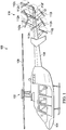
- FIG. 1 is a side-view schematic diagram of an exemplary helicopter 100 having an exemplary anti-torque matrix 110, depicted in this version with nine fixed or variable blade pitch motors 112a-112i, which can be electrically or hydraulically-driven motors.
- Helicopter 100 includes a rotary system 102 carried by a fuselage 104.
- Rotor blades 106 connected to rotary system 102 provide flight for helicopter 100.
- Rotor blades 106 are controlled by multiple controllers within fuselage 104. For example, during flight, a pilot can manipulate cyclic controllers for changing a pitch angle of rotor blades 106 and/or manipulate pedals to provide vertical, horizontal and yaw flight control.
- Helicopter 100 has a tail boom 108, which supports anti-torque matrix 110 at the aft end.
- Each of fixed or variable blade pitch motors 112a-112i can be operated individually or in groups to provide counter-torque force for transversely stabilizing helicopter 100.
- Each of fixed or variable blade pitch motors 112a-112i is mounted as part of anti-torque matrix 110 on tail boom 108.
- Anti-torque matrix 110 is centered on a hub such that a leading edge of anti-torque matrix 110 is presented to the side of helicopter 100 toward tail boom 108. For example, when a single main rotor helicopter 100 is rotating counter-clockwise when viewed from above, the leading edge of anti-torque matrix 110 is to the right (starboard) side of helicopter 100.
- FIG. 2 shows the use of multiple ducted rotors to generate anti-torque thrust.
- a helicopter 100 has anti-torque matrix 110, depicted in this version with nine fixed or variable blade pitch motors 112a-112i, which can be electrically or hydraulically-driven motors, each of which are individually ducted.
- Anti-torque matrix 110 can further include a surface 114 that forms part of the ducting for the nine-fixed or variable blade pitch motors 112a-112i.
- helicopter 100 includes a rotary system 102 carried by a fuselage 104. Rotor blades 106 connected to rotary system 102 provide flight for helicopter 100. Rotor blades 106 are controlled by multiple controllers within fuselage 104.
- Helicopter 100 has a tail boom 108, which supports anti-torque matrix 110 at the aft end, which also permits rotation of anti-torque matrix 110 about the longitudinal axis of tail boom 108.
- Each of fixed or variable blade pitch motors 112a-112i can be operated individually or in groups to provide counter-torque force for transversely stabilizing helicopter 100.
- Each of the fixed or variable blade pitch motors 112a-112i is mounted as part of anti-torque matrix 110 on tail boom 108.
- Anti-torque matrix 110 is centered on a hub such that a leading edge of anti-torque matrix 110 is presented to the side of helicopter 100 toward tail boom 108. For example, when a single main rotor helicopter 100 is rotating counter-clockwise when viewed from above, the leading edge of anti-torque matrix 110 is to the right (starboard) side of helicopter 100.
- anti-torque matrix 110 is oriented substantially in-plane with tail boom 108 of helicopter 100 during a first mode of helicopter operation.
- anti-torque matrix 110 may be a first anti-torque matrix 110, with a second anti-torque matrix 110 that is substantially parallel to the first providing additional motors and fixed or variable pitch blades that, generally, will be facing outwardly from each other, with the motors being in the center of anti-torque matrix 110.
- the motors will be co-axial, however, in certain embodiments the motors do not have to be co-axial.
- anti-torque matrix 110 can have any shape and include 2, 3, 4, 5, 6, 7, 8, 9, 10, 11, 12, 13, 14, 15 or more motors, which motors could also be in co-axial pairs.
- the anti-torque matrix 110 can have any shape, such as round, oval, crescent-shaped, J-shaped, diagonal, square, rectangular, triangular, pentagonal, hexagonal, polygonal, rhomboid, trapezoid, X-shaped, Y-shaped, or kite shaped,
- the first mode of helicopter operation is a hover mode, which is typically a mode in which helicopter 100 is sitting on or about the ground with anti-torque matrix 110 provides thrust from the one or more fixed or variable blade pitch motors 112a-112i when helicopter 100 is operating in slow speed flight.
- the anti-torque matrix 110 can provide maneuverability and trim to the helicopter operation.
- the direction of thrust of the one or more fixed or variable blade pitch motors 112a-112i of anti-torque matrix 110 can be in opposing directions, for example, one subset of motors can direct their thrust in one direction, while another subset can be directed in the opposite direction to provide finer rotational control to helicopter 100.
- the speed of the individual motors can also be varied, under control of a logic in a flight control computer that calculates the position of anti-torque matrix 110 during transition to and from the first to the second mode of operation and for independently controlling individual fan speeds to position the matrix for optimum thrust angle, as well as optimum thrust magnitude.
- anti-torque matrix 110 is oriented substantially off-plane with tail boom 108 of helicopter 100 during a second mode of helicopter operations that is different from the first mode.
- the second mode of helicopter operation is a flight mode (e.g., a low to high-speed forward flight mode).
- the orientation of anti-torque matrix 110 is changed from being substantially co-planar with tail boom 108 to being non-planar.
- anti-torque matrix 110 can be substantially perpendicular with the plane of tail boom 108, by pivoting about pivot.
- the orientation of anti-torque matrix 110 can be anywhere between co-planar and perpendicular relative to tail boom 108.
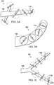
- Figures 3A-3F and Figures 4A-4F show several exemplary variations of matrix patterns of variable speed motors that provide high efficiency and reduced overall size.
- the skilled artisan will recognize that there are an infinite number of possible variations of number of rotors and pattern of rotor positions when using 2, 3, 4, 5, 6, 7, 8, 9, 10, 11, 12, 13, 14, 15 or more electric and/or hydraulic motors.
- the different motors can be ducted in groups of 2, 3, 4, 5, or more, again, having a variety of shapes and sizes.
- different motors may be different sizes and the blades may vary in size throughout the matrix.
- Figures 3A to 3F , and 4A to 4F show various schematic diagrams of anti-torque matrix with tail boom 108 of helicopter 100.
- anti-torque matrix 300 is mounted to tail boom 108 having a surface 114 and is depicted as having various electric motors and fixed pitch angle blades that are of different sizes and generally forming a triangular shape, with the apex of the triangle facing aft and anti-torque matrix 110 being generally vertical.
- Figure 4A shows the same configuration as in Figure 3A , in this case anti-torque matrix 400 is depicted with a pivot 412.
- Figure 3B shows an anti-torque matrix 302 is mounted to, or integral with, tail boom 108 having a surface 114 and is depicted as having a J-shape in which the various electric motors and fixed pitch angle blades have about the same size and are ducted.
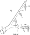
- Figure 4B shows a same configuration as in Figure 3B , in this case anti-torque matrix 402 is depicted with a pivot 412. However, in this configuration anti-torque matrix 402 shows a combination of in-plane variable speed motors and off-plane variable speed motors, which can also apply to all the configurations shown herein.
- Figure 3C shows an anti-torque matrix 304 is mounted to tail boom 108 having surfaces 114a and 114b and is depicted as having various electric motors and fixed pitch angle blades that are about the same size and generally form a triangular shape with the apex of the triangle facing forward.
- anti-torque matrix 304 oriented off-plane with tail boom 108 of helicopter 100 that is, anti-torque matrix 304 has been rotated on a Z-axis that passes between upper end axis 114a and lower end axis 114b perpendicular from an in-plane orientation.
- anti-torque matrix 304 can be pivoted on a horizontal X-axis to provide yaw control of helicopter 100.
- Figure 4C shows the same configuration as in Figure 3C , in this case anti-torque matrix 404 is depicted with a pivot 412.
- Figure 3D shows an anti-torque matrix 306 is mounted to tail boom 108 having surfaces 114a and 114b and is depicted as having various electric motors and fixed pitch angle blades that are about the same size and generally form a triangular shape with the apex of the triangle facing forward, however, in this embodiment the fork is horizontal.
- Figure 4D shows the same configuration as in Figure 3D , in this case anti-torque matrix 406 is depicted with a pivot 412.
- Figure 3E shows an anti-torque matrix 308 is mounted to tail boom 108 having a surface 114 and is depicted as having various electric motors and fixed pitch angle blades that are about the same size and generally form an X-shape, with two additional motors.
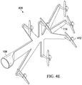
- Figure 4E shows the same configuration as in Figure 3E , in this case anti-torque matrix 408 is depicted with a pivot 412.
- Figure 3F shows an anti-torque matrix 310 is mounted to tail boom 108 having surfaces 114a and 114b and is depicted as having various electric motors and fixed pitch angle blades that are about the same size and generally form a crescent shape with the apex of the crescent facing forward.
- Figure 4F shows the same configuration as in Figure 3F , in this case anti-torque matrix 410 is depicted with a pivot 412.
- Figures 4A to 4F shows that a pivoting mechanism can be included with one or more of the fixed pitch rotors in anti-torque matrix 400-410 at the end of tail boom 108 of helicopter 100.
- the pivoting mechanism can be electric, or can even be a bell crank system and can include a pulley cable system connected to the bell crank system.
- the pivoting mechanism can be controlled by an operator of helicopter 100 to orient anti-torque matrix 400-410 substantially in-plane with tail boom 108 of helicopter 100 during a first mode of helicopter operation, and to orient anti-torque matrix 400-410 substantially off-plane with tail boom 108 of helicopter 100 during a second mode of helicopter operation that is different from the first mode.
- the pivoting mechanism can be controlled by a logic in a flight control computer that calculates the position of anti-torque matrix 400-410 during transition to and from the first to the second mode of operation and for independently controlling individual fan speeds to position the matrix for optimum thrust angle, as well as optimum thrust magnitude.
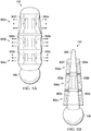
- Figure 5A is an rear, end view of anti-torque matrix 110 depicted in this version as sitting on tail boom 108, wherein anti-torque matrix 110 can be included at the end of tail boom 108 comprises two parallel sets of variable speed motors and fixed or variable angle blades 502a to 502f, that are shown within the body of anti-torque matrix 110, wherein variable speed motors 502a to 502f are co-axial and the blades are outwardly facing.
- Each pair of coaxial motors (502a and 502f, 502b and 502e, and 502c and 502d) is depicted as being within a duct 504a, 504b, 504c, respectively, and shows three pairs of motors that are internal to the tail boom.
- anti-torque matrix 110 has 6, 9, 12, or other number of pairs of motors, the end view only permits showing, in this version, the closest motors (502a-502f), however, additional pairs of motors and ducts can also be found forward from these motors.
- Figure 5B is an rear, end view of anti-torque matrix 110 depicted in this version as sitting on tail boom 108, wherein anti-torque matrix 110 can be included at the end of tail boom 108 comprises two parallel sets of variable speed motors and fixed or variable angle blades 502a to 502f, that are shown to extend from mast 506 of anti-torque matrix 110, wherein the variable speed motors 502a to 502f are co-axial and the blades are outwardly facing.
- Each pair of coaxial motors (502a and 502f, 502b and 502e, and 502c and 502d) is depicted as being within a duct 504a, 504b, 504c, respectively, and shows three pairs of motors.
- anti-torque matrix 110 has 6, 9, 12, or other number of pairs of motors, the end view only permits showing, in this version, the closest motors (502a-502f), however, additional pairs of motors and ducts can also be found forward from these motors.
- Figures 6A and 6B show the same configuration as Figures 5A and 5B , but in this configuration motors 602a-602f are connected to a pivoting mechanism 612.
- the pivoting mechanism 612 can be electric, mechanical, or can even be a bell crank system and can include a pulley cable system connected to the bell crank system.
- the aft portion of anti-torque matrix 110 is fitted with rearward grooves or openings in the aft portion of the tail rotor, for example, at mast 606, to add thrust to the rotorcraft.
- the pivoting mechanism can be controlled by an operator of helicopter 100 to orient anti-torque matrix 110 substantially in-plane with tail boom 108 of helicopter 100 during a first mode of helicopter operation, and to orient anti-torque matrix 110 substantially off-plane with tail boom 108 of helicopter 100 during a second mode of helicopter operation that is different from the first mode.
- the pivoting mechanism can be controlled by a logic in a flight control computer that calculates the position of anti-torque matrix 110 during transition to and from the first to the second mode of operation and for independently controlling individual fan speeds to position the matrix for optimum thrust angle, as well as optimum thrust magnitude.
- Figure 7 shows a flowchart of a control logic 700 for controlling the rotation of a helicopter that comprises the variable speed motors and fixed or variable angle blades in a matrix pattern.
- control logic 700 that can be, e.g., in a flight control computer, receives measurements of the rotation of the helicopter from, e.g., a rotation sensor.
- control logic 700 changes the speed of the one or more variable speed motors to increase torque or anti-torque to a desired rotation, which rotation can include no rotation.
- Control logic 700 can include looking up a table of known or estimated torque calculations or formulas for each of the variable speed motors depending on the size of the motor, blade, or position in the matrix.
- control logic 700 can look-up the estimated or measured effect on torque for each individual motor (or pairs of motors if co-axial), and then increase or decrease the speed to adjust the rotation of the helicopter.
- control logic 700 receives data from the rotation sensor that reflects actual helicopter rotation and in block 708, compares the estimate or calculated rotation of the helicopter versus actual rotation and can then adjust motor speed to change the speed of one or more of the variable speed motors and blades to control rotation, if any.
- Figure 8 shows a rotation control system 800 for use with the plurality of variable speed motors arranged in a first or a first and a second matrix.
- a control logic 802 is connected to a rotation sensor 804.
- Control logic 802 is also connected and controls the speed of the one or more fixed or variable pitch blade variable speed motors 810a-810i that are part of anti-torque module 808.
- Control logic 802 is also connected to a table 806 that includes the calculated torque versus speed for each of the one or more variable speed motors 810a-810i.
- Control logic 802 looks up estimated torques for the motors to adjust the speed of the motors based on a user-input for overall helicopter rotation (if any), then measures actual rotation, and finally adjusts the speed and torque of the one or more variable speed motors 810a-810i during flight operations.
- FIG. 9 illustrates an exemplary electric distributed propulsion anti-torque system 900.
- electric distributed propulsion anti-torque system 900 is an electric distributed propulsion anti-torque with dual flight control computers (FCC), dual power buses, and individual speed control units.
- Electric distributed propulsion anti-torque system 900 has a gearbox 902 that is connected to first and second generators 904a, 904b.
- Generator 904a is electrically connected via two separate system/buses 906a, 906b to electric motors 908a-908e, each of which has individual speed controls 910a-910e.
- Each of system/buses 906a, 906b and 906c, 906d is shown in the legend below to show the electrical connection from each of the first and second generators 904a, 904b.
- Generator 904b is electrically connected via two separate system/buses 906c, 906d to electric motors 908f-908j, each of which has individual speed controls 910f-910j.
- Electrical generators 904a, 904b are connect to a power management unit 914 that provide redundant power and is controlled via yaw control computers 912a, 912b (which can be the flight control computer).
- Each of system/buses 906a, 906b that connect to yaw control computers 912a, 912b can each act as a primary or a back-up for the other system/bus, thus providing complete, double redundant power to electric motors 908a-908e or electric motors 908f-908j.
- the skilled artisan will recognize that the electrical connections described herein can be used to control electrical power and control to hydraulic motors.
- FIG 10 illustrates another electric distributed propulsion anti-torque system 1000.
- electric distributed propulsion anti-torque system 1000 is an electric distributed propulsion anti-torque with dual flight control computers (FCC), dual power buses, and dual speed control units.
- Electric distributed propulsion anti-torque system 1000 has a gearbox 1002 that is connected to first and second generators 1004a, 1004b.
- Generator 1004a is electrically connected via two separate system/buses 1006a, 1006b to electric motors 1008a-1008e, each of which has individual speed controls 1010a-1010e.
- Generator 1004b is electrically connected via two separate system/buses 1006c, 1006d to electric motors 1008a-1008j, each of which has individual speed controls 1010f-1010j.
- System/buses 1006a and 1006b are directly connected to all electric motors 1008a-1008j, and are controlled by yaw control computers 1012a, 1012b (which can be the flight control computer), thereby providing double, redundant power and control to each of electric motors 1008a-1008j.
- yaw control computers 1012a, 1012b which can be the flight control computer
- Each of system/buses 1006a, 1006b that connect to yaw control computers 1012a, 1012b can each act as a primary or a back-up for the other system/bus, thus providing complete, double redundant power to electric motors 1008a-1008j.
- FIG 11 illustrates an exemplary architecture of an electric distributed propulsion system 1100, which may be implemented as an anti-torque system.
- electric distributed propulsion system 1100 has dual controllers, dual power buses, and dual speed control units and further includes dual channel input.
- Electric distributed propulsion system 1100 has a gearbox 1102 that is connected to first and second generators 1104a, 1104b.
- Generator 1104a is electrically connected via two separate system/buses 1106a, 1106b to fixed or variable pitch blade electric motors 1108a-1108e, each of which may have individual speed controls 1010a-1010e.
- Generator 1104b is electrically connected via two separate system/buses 1106c, 1106d to electric motors 1108a-1108j, each of which has individual speed controls 1110f-1110j.
- System/buses 1106a and 1106b are directly connected to all electric motors 1108a-1108j, and are controlled by controllers 1112a, 1112b (which can be the flight control computer), thereby providing double, redundant power and control to each of electric motors 1108a-1108j.
- controllers 1112a, 1112b which can be the flight control computer
- Each of system/buses 1106a, 1106b that connect to controllers 1112a, 1112b can each act as a primary or a back-up for the other system/bus, thus providing complete, double redundant power to electric motors 1108a-1108j.
- System 1100 includes dual channels 1114 and 1116 in communication between pilot input sensors generally designated 1118 and signal controllers 1112a, 1112b. Each channel 1120 is independent of the other channels 1120. Dual channels 1114 and 1116 include an additional channel 1122a and 1122b to provide redundant communication to the controllers from the pilot input sensors. In this example, pilot input sensors 1118 includes four sensors to provide triple redundancy for each of the controllers. Pilot input sensors 1118 may include or consist of a triplex sensor. Additionally, system 1110 includes cross communication between all the motor control units and signal controllers. In some embodiments, each of the controllers, dual channels, and respective input sensors may be replaced with a flight control computer. The primary and backup controllers may have a cross-communication function for data exchange, whereby upon failure of one controller the other controller can perform command functions. System 11 is not limited to dual components and systems and is illustrative of redundant architectures.
- FIG 12 illustrates another exemplary architecture of an electric distributed propulsion system 1200, which may be implemented as an anti-torque system.
- electric distributed propulsion anti-torque system 1200 includes dual controllers, dual power buses, and dual speed control units for redundant power and control.
- System 1200 is not limited to dual components and systems and is illustrative of redundant architectures.
- System 1200 is similar to system 1100 illustrated in Figure 11 and further includes an electric storage device 1250, e.g., a battery or ultracapacitor.
- an electric storage device 1250 e.g., a battery or ultracapacitor.
- Electric storage device 1250 is electrically connected via first connections 1252 to the plurality of motors to receive and store motor regenerative power and to provide stored electricity to the motors when generator power is unavailable or to boost the motor output once it is above the available generator power or operation requires higher power responsiveness and also to provide power for other onboard electrical devices.
- One or more of the generators maybe starter-generators or motor-generators.
- Electric storage device 1250 is electrically connected to the one or more starter- or motor-generators through second connections 1254.
- the starter or motor function may be powered with the stored electricity from storage device 1250 to start the engine, e.g. a turbine engine, by driving the engine until it rotates fast enough to support combustion.
- the starter or motor function may be used in accordance with some embodiments to drive the generator coils of one or more of the generators to generator and supply electricity to the motors, for example during an autorotation event.
- stored electricity is communicate from stored electric storage device to a generator 1204a and/or 1204b to drive the gearbox and the generator coils.
- the generator power may be used to power the motors and other onboard electrical devices.
- the blades (fans) in electric distributed propulsion systems may be too small to support autorotation and thus one or more of the motors need to be electrically powered to provide the necessary thrust for a safe landing.
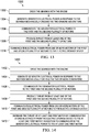
- Figure 13 illustrates an exemplary method 1300 of operating an aircraft with an electric distributed propulsion system, described with reference to the other figures.
- a gearbox is driven by an engine.
- the gearbox mechanically drives a generator that generates generator electrical power.
- the generator electrical power is communicated to the plurality of fixed or variable pitch blade motors, which at block 1308 produce thrust.
- regenerative electric power from one or more of the fixed or variable pitch blade motors is communicated to an electric storage device.
- FIG. 14 illustrates an exemplary method 1400 of operating an aircraft with an electric distributed propulsion system, described with reference to the other figures.
- a gearbox is driven by an engine.
- the gearbox mechanically drives a generator that generates generator electrical power.
- the generator electrical power is communicated to the plurality of fixed or variable pitch blade motors, which at block 1408 produce thrust.
- regenerative electric power from one or more of the fixed or variable pitch blade motors is communicated to an electric storage device.
- thrust from at least one first motor of the plurality of fixed or variable pitch blade motors is boosted by communicating stored electricity from the electric storage device to the first motor in addition to the generator electrical power supplied to the first motor.
- One or more of the generators may be a starter- or motor-generator and the electric storage device may power the starter- or motor-generator to start the engine or engines.
- FIG. 15 illustrates an exemplary method 1500 of operating an aircraft with an electric distributed propulsion system, described with reference to the other figures.
- a gearbox is driven by an engine.
- the gearbox mechanically drives a generator that generates generator electrical power.
- At least one of the generators is a starter- or motor-generator.
- the generator electrical power is communicated to the plurality of fixed or variable pitch blade motors, which at block 1508 produce thrust.
- regenerative electric power from one or more of the fixed or variable pitch blade motors is communicated to an electric storage device.
- the starter- or motor-generator is powered during flight with the stored electricity from the electric storage device, for example in response to engine failure.
- the starter or motor function of the starter- or motor-generator drives the gearbox and the gearbox drives the generator function of the one or more generators thereby supplying generator electricity to the plurality of fixed or variable pitch blade motors.
- FIG 16 illustrates an exemplary method 1600 of operating a helicopter with an electric distributed propulsion system, described with reference to the other figures.
- an engine drives a gearbox and the gearbox rotates a main rotor to provide lift.
- the gearbox mechanically drives one or more generators, which generate generator electrical power.
- At least one of the one or more generators is a starter- or motor-generator.
- the generator electrical power is communicated to a plurality of fixed or variable pitch blade motors that are located on a tail boom and at block 1608, one or more of the plurality of fixed or variable pitch blade motors produce thrust.
- the first and the second plurality of fixed or variable pitch blade motors may be oriented to produce thrust in opposite directions, thus the first plurality of fixed or variable pitch blade motors may produce thrust in an opposite direction from the second plurality of fixed or variable pitch blade motors.
- Regenerative electric power from one or more of the fixed or variable pitch blade motors may be communicated to an electric storage device.
- a starter- or motor-generator is powered, for example in response to engine failure, with the stored electricity from the electric storage device to drive the gearbox.
- the starter or motor function of the starter-or motor-generator drives the gearbox and the gearbox drives the generator function of the generators thereby supplying generator electricity to the plurality of fixed or variable pitch blade motors.
- anti-torque (or yaw) thrust is produced by the at least one of the first and the second plurality of fixed or variable pitch blade motors.
- the fixed or variable blade pitch electric motor module can be controlled by pilot inputs in combination with the operating status of the air vehicle (e.g., hover, transition or forward flight).
- the fixed or variable blade pitch electric motor module operation can be controlled by the computer system, which, in turn, can get cues from the pilot's inputs, etc.
- Gearbox is used herein to generally refer to gears and is not limited to the location of the gears.
- the gearbox may be gears incorporated in the engine, stand-alone gearboxes, auxiliary gearboxes, and/or a main gearbox.
- substantially is defined as largely but not necessarily wholly what is specified (and includes what is specified; e.g., substantially 90 degrees includes 90 degrees and substantially parallel includes parallel), as understood by a person of ordinary skill in the art.
- the extent to which the description may vary will depend on how great a change can be instituted and still have a person of ordinary skill in the art recognized the modified feature as still having the required characteristics and capabilities of the unmodified feature.
- a numerical value herein that is modified by a word of approximation such as “substantially,” “approximately,” and “about” may vary from the stated value, for example, by 0.1, 0.5, 1, 2, 3, 4, 5, 10, or 15 percent.
Landscapes
- Engineering & Computer Science (AREA)
- Aviation & Aerospace Engineering (AREA)
- Power Engineering (AREA)
- Mechanical Engineering (AREA)
- Physics & Mathematics (AREA)
- General Physics & Mathematics (AREA)
- Automation & Control Theory (AREA)
- Electric Propulsion And Braking For Vehicles (AREA)
- Transmission Devices (AREA)
Abstract
Description
- This disclosure relates in general to the field of aircraft, and more particularly, but not by way of limitation, to the field of flight control and redundant power and control for electric distributed propulsion.
- This section provides background information to facilitate a better understanding of the various aspects of the disclosure. It should be understood that the statements in this section of this document are to be read in this light, and not as admissions of prior art.
- Counter-torque tail rotors are often used in helicopters and are generally mounted adjacent to vertical fins that provide for aircraft stability. In such a configuration, the helicopter rotor produces a transverse airflow. Tail rotors can be driven at high angular velocities to provide adequate aerodynamic responses. Sometimes, vortices produced by a main helicopter rotor and the tail rotor can interact to reduce the efficiency of the thrust created by the rotors. The interference of the vortices may also cause an increase in noise. To address these issues, the vertical fin can be replaced by an annular airfoil (sometimes called a ring wing) having an inner diameter greater than the diameter of the tail rotor and which can be mounted around the tail rotor.
- An exemplary electric distributed propulsion system for an aircraft includes one or more generators connected to a gearbox, a first and a second plurality of motors connected to the one or more generators, wherein each motor of the first and second plurality of motors is connected to a blade to provide thrust, a first and a second power bus electrically connected between the one or more generators and the first and the second plurality of motors, wherein each power bus is independent of the other power bus, a first and a second controller independently connected to each of the first and second plurality of motors, wherein each of the first and second controllers serves as a primary and a backup controller to provide redundant control to both the first and the second plurality of motors, and dual channels in communication between pilot input sensors and the first and the second controllers, wherein each channel of the dual channels is independent of the other channels, and the dual channels comprise an additional channel to provide redundant communication to the first and second controllers.
- An exemplary method of operating an aircraft with an electric distributed propulsion system driving a gearbox with an engine, generating generator electrical power in response to the gearbox mechanically driving one or more generators, communicating the generator electrical power to a first and second plurality of motor individually driving rotors, producing thrust from at least one of the first and the second plurality of motors, communicating electrical power from one or more motors of the first and second plurality of motors to the electric storage device.
- An exemplary method of operating a helicopter having a main rotor and a first and second plurality of motors with blades located on a tail boom, includes driving the gearbox with an engine, the gearbox rotating a main rotor, generating generator electrical power in response to the gearbox mechanically driving one or more generators, wherein a first generator of the one or more generators is a starter- or motor-generator, communicating the generator electrical power to the first and the second plurality of motors located on a tail boom, producing thrust from at least one of the first and the second plurality of motors, powering, responsive for example to engine failure, the first generator with stored electricity from the electric storage device, driving the gearbox with the first generator thereby driving the one or more generators and supplying generator electrical power to the first and second plurality of motors, and producing thrust with at least one of the first and second plurality of motors.
- This summary is provided to introduce a selection of concepts that are further described below in the detailed description. This summary is not intended to identify key or essential features of the claimed subject matter, nor is it intended to be used as an aid in limiting the scope of claimed subject matter.
- The disclosure is best understood from the following detailed description when read with the accompanying figures. It is emphasized that, in accordance with standard practice in the industry, various features are not drawn to scale. In fact, the dimensions of various features may be arbitrarily increased or reduced for clarity of discussion.
-
Figure 1 is a side-view schematic diagram of an exemplary aircraft showing an exemplary electric distributed propulsion system arranged as an anti-torque matrix. -
Figure 2 shows the use of multiple ducted rotors to generate anti-torque thrust. -
Figures 3A-3F illustrate various schematic diagrams of exemplary anti-torque matrices. -
Figures 4A-4F illustrate additional schematic diagrams of exemplary anti-torque matrices. -
Figures 5A and 5B illustrate variants of co-axially positioned motors with outwardly facing blades (fan) in an exemplary electric distributed propulsion system. -
Figures 6A and 6B illustrate variants of co-axially positioned motors with outwardly facing blades in another exemplary electric distributed propulsion system. -
Figure 7 is a flowchart of an exemplary control logic for controlling the rotation of a helicopter that comprises an electric distributed propulsion system anti-torque system. -
Figure 8 illustrates an exemplary rotation control system for use with the plurality of fixed or variable pitch blade variable speed motors arranged in a first or a first and a second electric distributed propulsion matrix. -
Figure 9 illustrates an exemplary electric distributed propulsion anti-torque system. -
Figure 10 illustrates another electric distributed propulsion anti-torque system. -
Figure 11 illustrates an exemplary electric distributed propulsion system utilizing redundant control inputs. -
Figure 12 illustrates an exemplary electric distributed propulsion system incorporating electric storage capabilities. -
Figures 13 illustrates an exemplary method of operating an aircraft with an electric distributed propulsion system. -
Figures 14 illustrates another exemplary method of operating an aircraft with an electric distributed propulsion system. -
Figures 15 illustrates another exemplary method of operating an aircraft with an electric distributed propulsion system. -
Figures 16 illustrates an exemplary method of operating a helicopter with an electric distributed anti-torque system. - It is to be understood that the following disclosure provides many different embodiments, or examples, for implementing different features of various illustrative embodiments. Specific examples of components and arrangements are described below to simplify the disclosure. These are, of course, merely examples and are not intended to be limiting. For example, a figure may illustrate an exemplary embodiment with multiple features or combinations of features that are not required in one or more other embodiments and thus a figure may disclose one or more embodiments that have fewer features or a different combination of features than the illustrated embodiment. Embodiments may include some but not all the features illustrated in a figure and some embodiments may combine features illustrated in one figure with features illustrated in another figure. Therefore, combinations of features disclosed in the following detailed description may not be necessary to practice the teachings in the broadest sense and are instead merely to describe particularly representative examples. In addition, the disclosure may repeat reference numerals and/or letters in the various examples. This repetition is for the purpose of simplicity and clarity and does not itself dictate a relationship between the various embodiments and/or configurations discussed.
- In the specification, reference may be made to the spatial relationships between various components and to the spatial orientation of various aspects of components as the devices are depicted in the attached drawings. However, as will be recognized by those skilled in the art after a complete reading of the present application, the devices, members, apparatuses, etc. described herein may be positioned in any desired orientation. Thus, the use of terms such as "inboard," "outboard," "above," "below," "upper," "lower," or other like terms to describe a spatial relationship between various components or to describe the spatial orientation of aspects of such components should be understood to describe a relative relationship between the components or a spatial orientation of aspects of such components, respectively, as the device described herein may be oriented in any desired direction. As used herein, the terms "connect," "connection," "connected," "in connection with," and "connecting" may be used to mean in direct connection with or in connection with via one or more elements. Similarly, the terms "couple," "coupling," and "coupled" may be used to mean directly coupled or coupled via one or more elements.
- Most helicopters with a single, main rotor system require a separate rotor to overcome torque. This is traditionally accomplished on helicopters using a variable pitch, anti-torque rotor or tail rotor receiving power from the engine(s) through shafts and gearboxes. While many attempts have been made to power a traditional single tail rotor directly using a large electric motor to replace traditional shafts and gearboxes. These attempts proved to be impractical due for example to the excessive weight of an electric motor capable of providing the required torque and speed to power a traditional tail rotor. Additionally the safety reliability of a single or even a dual electric motor does not approach the safety reliability of shafts and gearboxes.
- Systems disclosed herein are directed to a redundant system to provide electrical power and computer control to an array of electric motors used to generate thrust, such as anti-torque thrust and yaw flight control on aircraft such as helicopters. The systems may use redundant generators and flight control computers in a unique architecture to provide necessary flight safety in the event of a component or system failure.
- Since electric motor power density becomes less practical with increasing motor size, "distributed propulsion" makes use a larger quantity of smaller motors. Combining the shaft output of multiple small motors into a single shaft output using a gearbox wipes out any weight savings and introduces thermal issues, which can require the addition of fluid cooling systems and even more weight. However, by distributing multiple small motors over the airframe, the total aircraft structural weight can be reduced by spreading smaller propulsion induced loads across the entire aircraft. Separating the motors by at least a rotor diameter also provides effective convection cooling. With existing electric power storage technology (batteries, fuel cells) the application of distributed propulsion on manned fixed wing aircraft is becoming more practical, but range is very limited. In the event of depletion of stored energy, a fixed wing aircraft can still possibly glide to a safe landing. This is not the same case with application of distributed propulsion for lift propulsion on helicopters. On helicopters with distributed propulsion, the rotational inertia of the multiple small rotors is inadequate to support autorotation for safe landing. This combined with the higher power demands required for vertical lift rotors makes pure electric helicopters impractical until a dramatic increase in electric power storage technology occurs.
- On manned helicopter configurations incorporating distributed propulsion, a dedicated system for anti-torque control is not required. Multiple small rotors cancel out each other's torque and changing rotor speeds can generate control yaw. Therefore, the application of distributed propulsion specifically for anti-torque control appears to have been overlooked.
- For example, using a Bell model 407 tail rotor for sizing analysis, using existing commercially available electric Sport Light application electric motors and propellers, it is possible to generate equivalent thrust with a matrix of 3 by 3 or 4 by 4 fixed or variable blade pitch electric motor modules in approximately the same disc area. With an approximate fixed or variable blade pitch electric motor module conservative weight of 5 pounds (2.2 kilos) (for 3 by 3 matrix), the total weight minus structure and system installation is 45 pounds (20 kilos). This weight is comparable to the current 407 rotor and gearbox weight. The one starter/generator on the 407 does not provide adequate power or reliability to support operation of the matrix of fixed or variable blade pitch motor modules. However, the elimination of the tail rotor output shaft provides for a main gearbox accessory drive pad to mount redundant generators. Because the added generator capacity is over sized for safety reliability, with both generators operating approximately 40 kW power can be made available for non-flight critical uses. Similar calculations apply to the use of hydraulic motors.
- Another advantage of the use of a matrix of fixed or variable blade pitch motor modules is that, in the event of loss of all aircraft engine power, the power demand for anti-torque control thrust becomes minimal. Therefore, the impact on the aircraft's electric power systems and rotor energy is also minimal in the event of an autorotation landing. With increasing forward flight speed the interaction of airflow between rotors results in the aft-most rotors losing their effectiveness. Commensurately, with increasing forward speed the anti-torque thrust required decreases. Therefore, with increasing forward speed the aft most modules will be progressively shut off to eliminate unneeded power consumption and reduce noise.
- Non-limiting examples of electric motors a self-commutated motor, an externally commutated motor, a brushed motor, a brushless motor, a linear motor, an AC/DC synchronized motor, an electronic commutated motor, a mechanical commutator motor (AC or DC), an asynchronous motor (AC or DC), a pancake motor, a three-phase motor, an induction motor, an electrically excited DC motor, a permanent magnet DC motor, a switched reluctance motor, an interior permanent magnet synchronous motor, a permanent magnet synchronous motor, a surface permanent magnet synchronous motor, a squirrel-cage induction motor, a switched reluctance motor, a synchronous reluctance motor, a variable-frequency drive motor, a wound-rotor induction motor, an ironless or coreless rotor motor, or a wound-rotor synchronous motor.
-
Figure 1 is a side-view schematic diagram of anexemplary helicopter 100 having an exemplaryanti-torque matrix 110, depicted in this version with nine fixed or variableblade pitch motors 112a-112i, which can be electrically or hydraulically-driven motors.Helicopter 100 includes arotary system 102 carried by afuselage 104.Rotor blades 106 connected torotary system 102 provide flight forhelicopter 100.Rotor blades 106 are controlled by multiple controllers withinfuselage 104. For example, during flight, a pilot can manipulate cyclic controllers for changing a pitch angle ofrotor blades 106 and/or manipulate pedals to provide vertical, horizontal and yaw flight control.Helicopter 100 has atail boom 108, which supportsanti-torque matrix 110 at the aft end. Each of fixed or variableblade pitch motors 112a-112i can be operated individually or in groups to provide counter-torque force for transversely stabilizinghelicopter 100. Each of fixed or variableblade pitch motors 112a-112i is mounted as part ofanti-torque matrix 110 ontail boom 108.Anti-torque matrix 110 is centered on a hub such that a leading edge ofanti-torque matrix 110 is presented to the side ofhelicopter 100 towardtail boom 108. For example, when a singlemain rotor helicopter 100 is rotating counter-clockwise when viewed from above, the leading edge ofanti-torque matrix 110 is to the right (starboard) side ofhelicopter 100. -
Figure 2 shows the use of multiple ducted rotors to generate anti-torque thrust. In this example ahelicopter 100 hasanti-torque matrix 110, depicted in this version with nine fixed or variableblade pitch motors 112a-112i, which can be electrically or hydraulically-driven motors, each of which are individually ducted.Anti-torque matrix 110 can further include asurface 114 that forms part of the ducting for the nine-fixed or variableblade pitch motors 112a-112i. As is the case with the helicopter inFigure 1 ,helicopter 100 includes arotary system 102 carried by afuselage 104.Rotor blades 106 connected torotary system 102 provide flight forhelicopter 100.Rotor blades 106 are controlled by multiple controllers withinfuselage 104. For example, during flight, a pilot can manipulate cyclic controllers for changing a pitch angle of therotor blades 106 and/or manipulate pedals to provide vertical, horizontal and yaw flight control.Helicopter 100 has atail boom 108, which supportsanti-torque matrix 110 at the aft end, which also permits rotation ofanti-torque matrix 110 about the longitudinal axis oftail boom 108. Each of fixed or variableblade pitch motors 112a-112i can be operated individually or in groups to provide counter-torque force for transversely stabilizinghelicopter 100. Each of the fixed or variableblade pitch motors 112a-112i is mounted as part ofanti-torque matrix 110 ontail boom 108.Anti-torque matrix 110 is centered on a hub such that a leading edge ofanti-torque matrix 110 is presented to the side ofhelicopter 100 towardtail boom 108. For example, when a singlemain rotor helicopter 100 is rotating counter-clockwise when viewed from above, the leading edge ofanti-torque matrix 110 is to the right (starboard) side ofhelicopter 100. - In operation,
anti-torque matrix 110 is oriented substantially in-plane withtail boom 108 ofhelicopter 100 during a first mode of helicopter operation. The skilled artisan will recognize thatanti-torque matrix 110 may be a firstanti-torque matrix 110, with a secondanti-torque matrix 110 that is substantially parallel to the first providing additional motors and fixed or variable pitch blades that, generally, will be facing outwardly from each other, with the motors being in the center ofanti-torque matrix 110. Generally, the motors will be co-axial, however, in certain embodiments the motors do not have to be co-axial. Further, whileFigures 1 and2 illustrateanti-torque matrix 110 are being in the form of a 3 by 3 matrix, that is generally rhomboid in shape, the skilled artisan will recognize thatanti-torque matrix 110 can have any shape and include 2, 3, 4, 5, 6, 7, 8, 9, 10, 11, 12, 13, 14, 15 or more motors, which motors could also be in co-axial pairs. Further, theanti-torque matrix 110 can have any shape, such as round, oval, crescent-shaped, J-shaped, diagonal, square, rectangular, triangular, pentagonal, hexagonal, polygonal, rhomboid, trapezoid, X-shaped, Y-shaped, or kite shaped, - For example, the first mode of helicopter operation is a hover mode, which is typically a mode in which
helicopter 100 is sitting on or about the ground withanti-torque matrix 110 provides thrust from the one or more fixed or variableblade pitch motors 112a-112i whenhelicopter 100 is operating in slow speed flight. In this orientation, theanti-torque matrix 110 can provide maneuverability and trim to the helicopter operation. During hover, the direction of thrust of the one or more fixed or variableblade pitch motors 112a-112i ofanti-torque matrix 110 can be in opposing directions, for example, one subset of motors can direct their thrust in one direction, while another subset can be directed in the opposite direction to provide finer rotational control to helicopter 100. Of course, the speed of the individual motors can also be varied, under control of a logic in a flight control computer that calculates the position ofanti-torque matrix 110 during transition to and from the first to the second mode of operation and for independently controlling individual fan speeds to position the matrix for optimum thrust angle, as well as optimum thrust magnitude. - In a second mode of operation,
anti-torque matrix 110 is oriented substantially off-plane withtail boom 108 ofhelicopter 100 during a second mode of helicopter operations that is different from the first mode. For example, the second mode of helicopter operation is a flight mode (e.g., a low to high-speed forward flight mode). In the flight mode, the orientation ofanti-torque matrix 110 is changed from being substantially co-planar withtail boom 108 to being non-planar. For example,anti-torque matrix 110 can be substantially perpendicular with the plane oftail boom 108, by pivoting about pivot. Alternatively, the orientation ofanti-torque matrix 110 can be anywhere between co-planar and perpendicular relative totail boom 108. -
Figures 3A-3F andFigures 4A-4F show several exemplary variations of matrix patterns of variable speed motors that provide high efficiency and reduced overall size. The skilled artisan will recognize that there are an infinite number of possible variations of number of rotors and pattern of rotor positions when using 2, 3, 4, 5, 6, 7, 8, 9, 10, 11, 12, 13, 14, 15 or more electric and/or hydraulic motors. Of course, the different motors can be ducted in groups of 2, 3, 4, 5, or more, again, having a variety of shapes and sizes. In addition, different motors may be different sizes and the blades may vary in size throughout the matrix. -
Figures 3A to 3F , and4A to 4F show various schematic diagrams of anti-torque matrix withtail boom 108 ofhelicopter 100. InFigure 3A anti-torque matrix 300 is mounted totail boom 108 having asurface 114 and is depicted as having various electric motors and fixed pitch angle blades that are of different sizes and generally forming a triangular shape, with the apex of the triangle facing aft andanti-torque matrix 110 being generally vertical.Figure 4A shows the same configuration as inFigure 3A , in this caseanti-torque matrix 400 is depicted with apivot 412.Figure 3B shows ananti-torque matrix 302 is mounted to, or integral with,tail boom 108 having asurface 114 and is depicted as having a J-shape in which the various electric motors and fixed pitch angle blades have about the same size and are ducted.Figure 4B shows a same configuration as inFigure 3B , in this caseanti-torque matrix 402 is depicted with apivot 412. However, in this configurationanti-torque matrix 402 shows a combination of in-plane variable speed motors and off-plane variable speed motors, which can also apply to all the configurations shown herein.Figure 3C shows ananti-torque matrix 304 is mounted totail boom 108 havingsurfaces Figure 3C ,anti-torque matrix 304 oriented off-plane withtail boom 108 ofhelicopter 100, that is,anti-torque matrix 304 has been rotated on a Z-axis that passes betweenupper end axis 114a andlower end axis 114b perpendicular from an in-plane orientation. In some implementations,anti-torque matrix 304 can be pivoted on a horizontal X-axis to provide yaw control ofhelicopter 100.Figure 4C shows the same configuration as inFigure 3C , in this caseanti-torque matrix 404 is depicted with apivot 412.Figure 3D shows ananti-torque matrix 306 is mounted totail boom 108 havingsurfaces Figure 4D shows the same configuration as inFigure 3D , in this caseanti-torque matrix 406 is depicted with apivot 412.Figure 3E shows ananti-torque matrix 308 is mounted totail boom 108 having asurface 114 and is depicted as having various electric motors and fixed pitch angle blades that are about the same size and generally form an X-shape, with two additional motors.Figure 4E shows the same configuration as inFigure 3E , in this caseanti-torque matrix 408 is depicted with apivot 412.Figure 3F shows ananti-torque matrix 310 is mounted totail boom 108 havingsurfaces Figure 4F shows the same configuration as inFigure 3F , in this caseanti-torque matrix 410 is depicted with apivot 412. -
Figures 4A to 4F shows that a pivoting mechanism can be included with one or more of the fixed pitch rotors in anti-torque matrix 400-410 at the end oftail boom 108 ofhelicopter 100. In some implementations, the pivoting mechanism can be electric, or can even be a bell crank system and can include a pulley cable system connected to the bell crank system. The pivoting mechanism can be controlled by an operator ofhelicopter 100 to orient anti-torque matrix 400-410 substantially in-plane withtail boom 108 ofhelicopter 100 during a first mode of helicopter operation, and to orient anti-torque matrix 400-410 substantially off-plane withtail boom 108 ofhelicopter 100 during a second mode of helicopter operation that is different from the first mode. In a fly-by-wire configuration, the pivoting mechanism can be controlled by a logic in a flight control computer that calculates the position of anti-torque matrix 400-410 during transition to and from the first to the second mode of operation and for independently controlling individual fan speeds to position the matrix for optimum thrust angle, as well as optimum thrust magnitude. -
Figure 5A is an rear, end view ofanti-torque matrix 110 depicted in this version as sitting ontail boom 108, whereinanti-torque matrix 110 can be included at the end oftail boom 108 comprises two parallel sets of variable speed motors and fixed orvariable angle blades 502a to 502f, that are shown within the body ofanti-torque matrix 110, whereinvariable speed motors 502a to 502f are co-axial and the blades are outwardly facing. Each pair of coaxial motors (502a and 502f, 502b and 502e, and 502c and 502d) is depicted as being within aduct anti-torque matrix 110 has 6, 9, 12, or other number of pairs of motors, the end view only permits showing, in this version, the closest motors (502a-502f), however, additional pairs of motors and ducts can also be found forward from these motors. -
Figure 5B is an rear, end view ofanti-torque matrix 110 depicted in this version as sitting ontail boom 108, whereinanti-torque matrix 110 can be included at the end oftail boom 108 comprises two parallel sets of variable speed motors and fixed orvariable angle blades 502a to 502f, that are shown to extend frommast 506 ofanti-torque matrix 110, wherein thevariable speed motors 502a to 502f are co-axial and the blades are outwardly facing. Each pair of coaxial motors (502a and 502f, 502b and 502e, and 502c and 502d) is depicted as being within aduct anti-torque matrix 110 has 6, 9, 12, or other number of pairs of motors, the end view only permits showing, in this version, the closest motors (502a-502f), however, additional pairs of motors and ducts can also be found forward from these motors. -
Figures 6A and 6B show the same configuration asFigures 5A and 5B , but in thisconfiguration motors 602a-602f are connected to apivoting mechanism 612. Thepivoting mechanism 612 can be electric, mechanical, or can even be a bell crank system and can include a pulley cable system connected to the bell crank system. In the configurations shown inFigures 6A and 6B , the aft portion ofanti-torque matrix 110 is fitted with rearward grooves or openings in the aft portion of the tail rotor, for example, atmast 606, to add thrust to the rotorcraft. The pivoting mechanism can be controlled by an operator ofhelicopter 100 to orientanti-torque matrix 110 substantially in-plane withtail boom 108 ofhelicopter 100 during a first mode of helicopter operation, and to orientanti-torque matrix 110 substantially off-plane withtail boom 108 ofhelicopter 100 during a second mode of helicopter operation that is different from the first mode. In a fly-by-wire configuration, the pivoting mechanism can be controlled by a logic in a flight control computer that calculates the position ofanti-torque matrix 110 during transition to and from the first to the second mode of operation and for independently controlling individual fan speeds to position the matrix for optimum thrust angle, as well as optimum thrust magnitude. -
Figure 7 shows a flowchart of acontrol logic 700 for controlling the rotation of a helicopter that comprises the variable speed motors and fixed or variable angle blades in a matrix pattern. Inblock 702,control logic 700 that can be, e.g., in a flight control computer, receives measurements of the rotation of the helicopter from, e.g., a rotation sensor. Inblock 704,control logic 700 changes the speed of the one or more variable speed motors to increase torque or anti-torque to a desired rotation, which rotation can include no rotation.Control logic 700 can include looking up a table of known or estimated torque calculations or formulas for each of the variable speed motors depending on the size of the motor, blade, or position in the matrix. The position of the variable speed motors in the matrix will significantly affect their individual effect on the rotation of the helicopter. For example, assuming all the variable speed motors and blades are of equivalent size and power, then the variable speed motors and blades that are at the aft-most position will have the greatest effect on torque, while variable speed motors and blades that are fore from other motors will have less overall torque, assuming the same speed. As such,control logic 700 can look-up the estimated or measured effect on torque for each individual motor (or pairs of motors if co-axial), and then increase or decrease the speed to adjust the rotation of the helicopter. Inblock 706,control logic 700 receives data from the rotation sensor that reflects actual helicopter rotation and inblock 708, compares the estimate or calculated rotation of the helicopter versus actual rotation and can then adjust motor speed to change the speed of one or more of the variable speed motors and blades to control rotation, if any. -
Figure 8 shows arotation control system 800 for use with the plurality of variable speed motors arranged in a first or a first and a second matrix. Acontrol logic 802 is connected to arotation sensor 804.Control logic 802 is also connected and controls the speed of the one or more fixed or variable pitch bladevariable speed motors 810a-810i that are part ofanti-torque module 808.Control logic 802 is also connected to a table 806 that includes the calculated torque versus speed for each of the one or morevariable speed motors 810a-810i.Control logic 802 looks up estimated torques for the motors to adjust the speed of the motors based on a user-input for overall helicopter rotation (if any), then measures actual rotation, and finally adjusts the speed and torque of the one or morevariable speed motors 810a-810i during flight operations. -
Figure 9 illustrates an exemplary electric distributed propulsionanti-torque system 900. In this configuration, electric distributed propulsionanti-torque system 900 is an electric distributed propulsion anti-torque with dual flight control computers (FCC), dual power buses, and individual speed control units. Electric distributed propulsionanti-torque system 900 has agearbox 902 that is connected to first andsecond generators Generator 904a is electrically connected via two separate system/buses electric motors 908a-908e, each of which has individual speed controls 910a-910e. Each of system/buses second generators Generator 904b is electrically connected via two separate system/buses electric motors 908f-908j, each of which has individual speed controls 910f-910j.Electrical generators power management unit 914 that provide redundant power and is controlled viayaw control computers buses control computers electric motors 908a-908e orelectric motors 908f-908j. The skilled artisan will recognize that the electrical connections described herein can be used to control electrical power and control to hydraulic motors. -
Figure 10 illustrates another electric distributedpropulsion anti-torque system 1000. In this configuration, electric distributedpropulsion anti-torque system 1000 is an electric distributed propulsion anti-torque with dual flight control computers (FCC), dual power buses, and dual speed control units. Electric distributedpropulsion anti-torque system 1000 has agearbox 1002 that is connected to first andsecond generators Generator 1004a is electrically connected via two separate system/buses electric motors 1008a-1008e, each of which has individual speed controls 1010a-1010e.Generator 1004b is electrically connected via two separate system/buses electric motors 1008a-1008j, each of which hasindividual speed controls 1010f-1010j. System/buses electric motors 1008a-1008j, and are controlled byyaw control computers electric motors 1008a-1008j. Each of system/buses control computers electric motors 1008a-1008j. This configuration is shown without a separate power management system, but the skilled artisan will recognize that these systems are not mutually exclusive, but would provide for both a power management system and the double, redundant connections to each of the electric motors. The skilled artisan will recognize that the electrical connections described herein can be used to control electrical power and control to hydraulic motors. -
Figure 11 illustrates an exemplary architecture of an electric distributedpropulsion system 1100, which may be implemented as an anti-torque system. In this configuration, electric distributedpropulsion system 1100 has dual controllers, dual power buses, and dual speed control units and further includes dual channel input. Electric distributedpropulsion system 1100 has agearbox 1102 that is connected to first andsecond generators Generator 1104a is electrically connected via two separate system/buses electric motors 1108a-1108e, each of which may have individual speed controls 1010a-1010e.Generator 1104b is electrically connected via two separate system/buses electric motors 1108a-1108j, each of which hasindividual speed controls 1110f-1110j. System/buses electric motors 1108a-1108j, and are controlled bycontrollers electric motors 1108a-1108j. Each of system/buses controllers electric motors 1108a-1108j. This configuration is shown without a separate power management system, but the skilled artisan will recognize that these systems are not mutually exclusive, but would provide for both a power management system and the double, redundant connections to each of the electric motors. The skilled artisan will recognize that the electrical connections described herein can be used to control electrical power and control to hydraulic motors. -
System 1100 includesdual channels signal controllers channel 1120 is independent of theother channels 1120.Dual channels additional channel pilot input sensors 1118 includes four sensors to provide triple redundancy for each of the controllers.Pilot input sensors 1118 may include or consist of a triplex sensor. Additionally, system 1110 includes cross communication between all the motor control units and signal controllers. In some embodiments, each of the controllers, dual channels, and respective input sensors may be replaced with a flight control computer. The primary and backup controllers may have a cross-communication function for data exchange, whereby upon failure of one controller the other controller can perform command functions.System 11 is not limited to dual components and systems and is illustrative of redundant architectures. -
Figure 12 illustrates another exemplary architecture of an electric distributed propulsion system 1200, which may be implemented as an anti-torque system. In this configuration, electric distributed propulsion anti-torque system 1200 includes dual controllers, dual power buses, and dual speed control units for redundant power and control. System 1200 is not limited to dual components and systems and is illustrative of redundant architectures. System 1200 is similar tosystem 1100 illustrated inFigure 11 and further includes anelectric storage device 1250, e.g., a battery or ultracapacitor.Electric storage device 1250 is electrically connected viafirst connections 1252 to the plurality of motors to receive and store motor regenerative power and to provide stored electricity to the motors when generator power is unavailable or to boost the motor output once it is above the available generator power or operation requires higher power responsiveness and also to provide power for other onboard electrical devices. - One or more of the generators maybe starter-generators or motor-generators.
Electric storage device 1250 is electrically connected to the one or more starter- or motor-generators throughsecond connections 1254. The starter or motor function may be powered with the stored electricity fromstorage device 1250 to start the engine, e.g. a turbine engine, by driving the engine until it rotates fast enough to support combustion. The starter or motor function may be used in accordance with some embodiments to drive the generator coils of one or more of the generators to generator and supply electricity to the motors, for example during an autorotation event. For example, stored electricity is communicate from stored electric storage device to agenerator 1204a and/or 1204b to drive the gearbox and the generator coils. The generator power may be used to power the motors and other onboard electrical devices. The blades (fans) in electric distributed propulsion systems may be too small to support autorotation and thus one or more of the motors need to be electrically powered to provide the necessary thrust for a safe landing. -
Figure 13 illustrates anexemplary method 1300 of operating an aircraft with an electric distributed propulsion system, described with reference to the other figures. Atblock 1302, a gearbox is driven by an engine. Atblock 1304, the gearbox mechanically drives a generator that generates generator electrical power. Atblock 1306, the generator electrical power is communicated to the plurality of fixed or variable pitch blade motors, which atblock 1308 produce thrust. Atblock 1310, regenerative electric power from one or more of the fixed or variable pitch blade motors is communicated to an electric storage device. -
Figure 14 illustrates anexemplary method 1400 of operating an aircraft with an electric distributed propulsion system, described with reference to the other figures. Atblock 1402, a gearbox is driven by an engine. Atblock 1404, the gearbox mechanically drives a generator that generates generator electrical power. Atblock 1406, the generator electrical power is communicated to the plurality of fixed or variable pitch blade motors, which atblock 1408 produce thrust. Atblock 1410, regenerative electric power from one or more of the fixed or variable pitch blade motors is communicated to an electric storage device. Atblock 1412, thrust from at least one first motor of the plurality of fixed or variable pitch blade motors is boosted by communicating stored electricity from the electric storage device to the first motor in addition to the generator electrical power supplied to the first motor. One or more of the generators may be a starter- or motor-generator and the electric storage device may power the starter- or motor-generator to start the engine or engines. -
Figure 15 illustrates anexemplary method 1500 of operating an aircraft with an electric distributed propulsion system, described with reference to the other figures. Atblock 1502, a gearbox is driven by an engine. Atblock 1504, the gearbox mechanically drives a generator that generates generator electrical power. At least one of the generators is a starter- or motor-generator. Atblock 1506, the generator electrical power is communicated to the plurality of fixed or variable pitch blade motors, which atblock 1508 produce thrust. Atblock 1510, regenerative electric power from one or more of the fixed or variable pitch blade motors is communicated to an electric storage device. Atblock 1512, the starter- or motor-generator is powered during flight with the stored electricity from the electric storage device, for example in response to engine failure. Atblock 1514, the starter or motor function of the starter- or motor-generator drives the gearbox and the gearbox drives the generator function of the one or more generators thereby supplying generator electricity to the plurality of fixed or variable pitch blade motors. -
Figure 16 illustrates anexemplary method 1600 of operating a helicopter with an electric distributed propulsion system, described with reference to the other figures. Atblock 1602, an engine drives a gearbox and the gearbox rotates a main rotor to provide lift. Atblock 1604, the gearbox mechanically drives one or more generators, which generate generator electrical power. At least one of the one or more generators is a starter- or motor-generator. Atblock 1606, the generator electrical power is communicated to a plurality of fixed or variable pitch blade motors that are located on a tail boom and atblock 1608, one or more of the plurality of fixed or variable pitch blade motors produce thrust. The first and the second plurality of fixed or variable pitch blade motors may be oriented to produce thrust in opposite directions, thus the first plurality of fixed or variable pitch blade motors may produce thrust in an opposite direction from the second plurality of fixed or variable pitch blade motors. Regenerative electric power from one or more of the fixed or variable pitch blade motors may be communicated to an electric storage device. Atblock 1610, a starter- or motor-generator is powered, for example in response to engine failure, with the stored electricity from the electric storage device to drive the gearbox. Atblock 1612, the starter or motor function of the starter-or motor-generator drives the gearbox and the gearbox drives the generator function of the generators thereby supplying generator electricity to the plurality of fixed or variable pitch blade motors. Atblock 1614, anti-torque (or yaw) thrust is produced by the at least one of the first and the second plurality of fixed or variable pitch blade motors. - A number of implementations have been described. Nevertheless, it will be understood that various modifications may be made without departing from the spirit and scope of the disclosure. In some implementations, the fixed or variable blade pitch electric motor module can be controlled by pilot inputs in combination with the operating status of the air vehicle (e.g., hover, transition or forward flight). In implementations in which the rotorcraft is operated using some form of fly-by-wire or fly-by-light control systems, the fixed or variable blade pitch electric motor module operation can be controlled by the computer system, which, in turn, can get cues from the pilot's inputs, etc. Although various embodiments are described with reference to two or more generators, it is recognized that the architecture may utilize one or more generators. Gearbox is used herein to generally refer to gears and is not limited to the location of the gears. For example, and without limitation, the gearbox may be gears incorporated in the engine, stand-alone gearboxes, auxiliary gearboxes, and/or a main gearbox.
- Conditional language used herein, such as, among others, "can," "might," "may," "e.g.," and the like, unless specifically stated otherwise, or otherwise understood within the context as used, is generally intended to convey that certain embodiments include, while other embodiments do not include, certain features, elements and/or states. Thus, such conditional language is not generally intended to imply that features, elements and/or states are in any way required for one or more embodiments or that one or more embodiments necessarily include such elements or features.
- The term "substantially," "approximately," and "about" is defined as largely but not necessarily wholly what is specified (and includes what is specified; e.g., substantially 90 degrees includes 90 degrees and substantially parallel includes parallel), as understood by a person of ordinary skill in the art. The extent to which the description may vary will depend on how great a change can be instituted and still have a person of ordinary skill in the art recognized the modified feature as still having the required characteristics and capabilities of the unmodified feature. In general, but subject to the preceding, a numerical value herein that is modified by a word of approximation such as "substantially," "approximately," and "about" may vary from the stated value, for example, by 0.1, 0.5, 1, 2, 3, 4, 5, 10, or 15 percent.
- The foregoing outlines features of several embodiments so that those skilled in the art may better understand the aspects of the disclosure. Those skilled in the art should appreciate that they may readily use the disclosure as a basis for designing or modifying other processes and structures for carrying out the same purposes and/or achieving the same advantages of the embodiments introduced herein. Those skilled in the art should also realize that such equivalent constructions do not depart from the spirit and scope of the disclosure and that they may make various changes, substitutions, and alterations without departing from the spirit and scope of the disclosure. The scope of the invention should be determined only by the language of the claims that follow. The term "comprising" within the claims is intended to mean "including at least" such that the recited listing of elements in a claim are an open group. The terms "a," "an" and other singular terms are intended to include the plural forms thereof unless specifically excluded.
Claims (14)
- An electric distributed propulsion system, the system comprising:one or more generators connected to a gearbox;a first and a second plurality of motors connected to the one or more generators, wherein each motor of the first and second plurality of motors is connected to a blade to provide thrust;a first and a second power bus electrically connected between the one or more generators and the first and the second plurality of motors, wherein each power bus is independent of the other power bus;a first and a second controller independently connected to each of the first and second plurality of motors, wherein each of the first and second controllers serves as a primary and a backup controller to provide redundant control to both the first and the second plurality of motors; anddual channels in communication between pilot input sensors and the first and the second controllers, wherein each channel of the dual channels is independent of the other channels, and the dual channels comprise an additional channel to provide redundant communication to the first and second controllers.
- The system of claim 1, wherein:the pilot input sensors comprise four sensors to provide triple redundancy for each of the first and the second controllers; orthe pilot input sensors comprise or consist of a triplex sensor.
- The system of claim 1 or claim 2, further comprising:a first flight control computer comprising the first controller and first pilot input sensors; anda second flight control computer comprising the second controller and second pilot input sensors.
- The system of any preceding claim, further comprising an electric storage device electrically connected to the one or more generators through first connections and the electric storage device electrically connected to the first and second plurality of motors through second connections.
- A method of operating an aircraft, the aircraft comprising:operating an aircraft comprising an engine and one or more generators connected to a gearbox, a first and a second plurality of motors connected to the one or more generators, wherein each motor of the first and second plurality of motors is connected to a blade to provide thrust, a first and a second power bus electrically connected between the one or more generators and the first and the second plurality of motors, wherein each power bus is independent of the other power bus, a first and a second controller independently connected to each of the first and second plurality of motors, wherein each of the first and second controllers serves as a primary and a backup controller to provide redundant control to both the first and the second plurality of motors, and an electric storage device electrically connected to the one or more generators through first connections and the electric storage device electrically connected to the first and second plurality of motors through second connections;driving the gearbox with the engine;generating generator electrical power in response to the gearbox mechanically driving the one or more generators;communicating the generator electrical power to the first and the second plurality of motors;producing thrust from at least one of the first and the second plurality of motors; andcommunicating electrical power from one or more motors of the first and second plurality of motors to the electric storage device.
- The method of claim 5, further comprising communicating stored electricity from the electric storage device to at least one first motor of the first and second plurality of motors.
- The method of claim 5 or claim 6, further comprising increasing the thrust of at least one first motor of the first and second plurality of motors, the increasing the thrust comprising communicating stored electricity from the electric storage device to the at least one first motor in addition to communicating the generator electrical power to the at least one first motor.
- The method of any one of claims 5 to 7, further comprising communicating stored electricity from the electric storage devices to one or more motors of the first and second plurality of motors in response to failure of one or more of the one or more generators.
- The method of any one of claims 5 to 8, wherein a first generator of the one or more generators is a starter- or motor-generator and further comprising:
starting the engine with the first generator, the starting including communicating stored electricity from the electric storage device to the first generator. - The method of any one of claims 5 to 9, wherein a first generator of the one or more generators is a starter- or motor-generator and further comprising:powering, responsive to failure of the engine during flight, the first generator with stored electricity from the electric storage device; anddriving the gearbox with the first generator thereby driving the one or more generators thereby supplying generator electrical power to the first and second plurality of motors.
- The method of any one of claims 5 to 10, wherein the aircraft is a helicopter, the first and second plurality of motors are located on a tail boom, the gearbox drives a main rotor, and at least a first generator of the one or more generators is a starter- or motor-generator.
- The method of claim 11, further comprising starting the engine with the first generator, the starting including communicating stored electricity from the electric storage device to the first generator.
- The method of claim 11 or claim 12, further comprising:powering, responsive to failure of the engine during flight and autorotation of the main rotor, the first generator with stored electricity from the electric storage device;driving the gearbox with the first generator, the gearbox thereby driving the one or more generators and communicating generator electrical power to the first and second plurality of motors; andproducing anti-torque thrust with at least one of the first and second plurality of motors.
- The method of claim 13, further comprising dual channels in communication with pilot input sensors and the first and the second controllers, wherein each channel of the dual channels is independent of the other channels, and each of the dual channels comprises an additional channel to provide redundant communication to the first and second controllers.
Applications Claiming Priority (1)
| Application Number | Priority Date | Filing Date | Title |
|---|---|---|---|
| US16/905,657 US11772807B2 (en) | 2020-06-18 | 2020-06-18 | Electric distributed anti-torque architecture |
Publications (2)
| Publication Number | Publication Date |
|---|---|
| EP3925887A1 true EP3925887A1 (en) | 2021-12-22 |
| EP3925887B1 EP3925887B1 (en) | 2023-06-07 |
Family
ID=75746467
Family Applications (1)
| Application Number | Title | Priority Date | Filing Date |
|---|---|---|---|
| EP21171545.3A Active EP3925887B1 (en) | 2020-06-18 | 2021-04-30 | Electric distributed anti-torque architecture |
Country Status (3)
| Country | Link |
|---|---|
| US (1) | US11772807B2 (en) |
| EP (1) | EP3925887B1 (en) |
| CA (1) | CA3117164C (en) |
Cited By (1)
| Publication number | Priority date | Publication date | Assignee | Title |
|---|---|---|---|---|
| EP4008630B1 (en) * | 2020-12-01 | 2023-08-23 | Textron Innovations Inc. | Power management systems for electrically distributed yaw control systems |
Families Citing this family (4)
| Publication number | Priority date | Publication date | Assignee | Title |
|---|---|---|---|---|
| US12444967B2 (en) * | 2020-11-05 | 2025-10-14 | Alarm.Com Incorporated | Smart generator |
| US12448924B2 (en) | 2022-04-13 | 2025-10-21 | Rtx Corporation | Aircraft hybrid duplex-triplex control architecture |
| CN115610674B (en) * | 2022-09-15 | 2026-05-05 | 亿航智能设备有限公司 | Battery management system and aircraft with multiple backup communication hosts |
| CN117068381B (en) * | 2023-08-24 | 2025-08-22 | 沈阳航空航天大学 | A dual-redundant electric power system suitable for light electric helicopters |
Citations (7)
| Publication number | Priority date | Publication date | Assignee | Title |
|---|---|---|---|---|
| GB1597318A (en) * | 1978-04-20 | 1981-09-03 | Boeing Co | Signal selector/monitor with weighed selector capability |
| US20130311006A1 (en) * | 2012-05-18 | 2013-11-21 | Rockwell Collins, Inc. | Triplex cockpit control data acquisition electronics |
| US20160107748A1 (en) * | 2013-06-12 | 2016-04-21 | The Boeing Company | Hybrid power rotary wing aircraft |
| US20170081019A1 (en) * | 2007-04-05 | 2017-03-23 | Bombardier Inc. | Fly-by-wire flight control system and method |
| US20170349276A1 (en) * | 2016-06-03 | 2017-12-07 | Bell Helicopter Textron Inc. | Electric distributed propulsion anti-torque redundant power and control system |
| WO2019123419A1 (en) * | 2017-12-22 | 2019-06-27 | Leonardo S.P.A. | Helicopter with an anti-torque system |
| US20200017206A1 (en) * | 2018-07-12 | 2020-01-16 | Sikorsky Aircraft Corporation | Tail rotor system including an electric motor |
Family Cites Families (43)
| Publication number | Priority date | Publication date | Assignee | Title |
|---|---|---|---|---|
| US4953098A (en) * | 1988-10-13 | 1990-08-28 | United Technologies Corporation | Higher harmonic control system for X-Wing aircraft |
| US5694014A (en) | 1995-08-22 | 1997-12-02 | Honeywell Inc. | Active hand controller redundancy and architecture |
| US5806805A (en) * | 1996-08-07 | 1998-09-15 | The Boeing Company | Fault tolerant actuation system for flight control actuators |
| WO2014198641A1 (en) | 2013-06-09 | 2014-12-18 | Eth Zurich | Volitant vehicle rotating about an axis and method for controlling the same |
| US10071801B2 (en) * | 2013-08-13 | 2018-09-11 | The United States Of America As Represented By The Administrator Of Nasa | Tri-rotor aircraft capable of vertical takeoff and landing and transitioning to forward flight |
| EP2889711B1 (en) * | 2013-12-30 | 2020-07-01 | Rolls-Royce Corporation | System and method for optimizing component life in a power system |
| CA2936329A1 (en) * | 2014-01-07 | 2015-07-16 | 4525612 Canada Inc. Dba Maginaire | Personal flight vehicle |
| CN203786564U (en) * | 2014-04-22 | 2014-08-20 | 零度智控(北京)智能科技有限公司 | Dual-redundancy flight control system |
| WO2016093905A1 (en) * | 2014-08-29 | 2016-06-16 | Tzunum Aircraft Llc | System and methods for implementing regional air transit network using hybrid-electric aircraft |
| FR3027058B1 (en) * | 2014-10-13 | 2016-11-04 | Turbomeca | ARCHITECTURE OF A PROPELLANT HELICOPTER SYSTEM COMPRISING A HYBRID TURBOMOTOR AND A REACTIVATION SYSTEM OF THE HYBRID TURBOMOTOR |
| CN105517902B (en) | 2014-10-20 | 2017-09-08 | 深圳市大疆创新科技有限公司 | UAV motor drive intelligent power control system and method and UAV |
| JP2017100651A (en) | 2015-12-04 | 2017-06-08 | 株式会社Soken | Flight equipment |
| EP3184425B1 (en) * | 2015-12-21 | 2018-09-12 | AIRBUS HELICOPTERS DEUTSCHLAND GmbH | Multirotor aircraft |
| US10926874B2 (en) * | 2016-01-15 | 2021-02-23 | Aurora Flight Sciences Corporation | Hybrid propulsion vertical take-off and landing aircraft |
| US10676183B2 (en) | 2016-05-13 | 2020-06-09 | Bell Helicopter Textron Inc. | Forward folding rotor blades |
| CA3099918C (en) | 2016-05-13 | 2023-06-13 | Bell Helicopter Textron Inc. | Distributed propulsion |
| US10703471B2 (en) | 2016-06-03 | 2020-07-07 | Bell Helicopter Textron Inc. | Anti-torque control using matrix of fixed blade pitch motor modules |
| US10377479B2 (en) | 2016-06-03 | 2019-08-13 | Bell Helicopter Textron Inc. | Variable directional thrust for helicopter tail anti-torque system |
| US10501193B2 (en) | 2016-07-01 | 2019-12-10 | Textron Innovations Inc. | Aircraft having a versatile propulsion system |
| US10737798B2 (en) | 2016-09-12 | 2020-08-11 | Ansel Misfeldt | Integrated feedback to flight controller |
| FR3057243B1 (en) * | 2016-10-12 | 2018-10-05 | Airbus Helicopters | ELECTRICAL CONTROL DEVICE, ROTARY WING AIRCRAFT AND METHOD |
| US11046448B2 (en) | 2016-12-20 | 2021-06-29 | Textron Innovations Inc. | Engine cooling systems for aircraft |
| US10934008B2 (en) * | 2017-02-10 | 2021-03-02 | General Electric Company | Dual function aircraft |
| WO2018175349A1 (en) * | 2017-03-19 | 2018-09-27 | Zunum Aero, Inc. | Hybrid-electric aircraft, and methods, apparatus and systems for facilitating same |
| US11186185B2 (en) | 2017-05-31 | 2021-11-30 | Textron Innovations Inc. | Rotor brake effect by using electric distributed anti-torque generators and opposing electric motor thrust to slow a main rotor |
| WO2019074859A2 (en) | 2017-10-11 | 2019-04-18 | Purdue Research Foundation | Displacement control hydrostatic propulsion system for multirotor vertical take off and landing aircraft |
| US11433997B2 (en) | 2017-10-30 | 2022-09-06 | Textron Innovations Inc. | Rotorcraft anti-torque systems and methods therefor |
| US10611496B2 (en) | 2018-01-22 | 2020-04-07 | Textron Innovations Inc. | Power allocation systems for aircraft |
| US11148820B1 (en) * | 2018-02-19 | 2021-10-19 | Parallel Flight Technologies, Inc. | System defining a hybrid power unit for thrust generation in an aerial vehicle and method for controlling the same |
| WO2019217920A1 (en) * | 2018-05-10 | 2019-11-14 | Joby Aero, Inc. | Electric tiltrotor aircraft |
| GB201812791D0 (en) * | 2018-08-07 | 2018-09-19 | Rolls Royce Plc | Gas turbine engine system with electrical power extraction |
| US11332256B2 (en) | 2018-08-21 | 2022-05-17 | General Electric Company | Fault tolerant hybrid electric propulsion system for an aerial vehicle |
| US20200070966A1 (en) | 2018-09-05 | 2020-03-05 | Bell Helicopter Textron Inc. | Stuck in Detent Monitors for Collective and Cyclic Sticks |
| US11099936B2 (en) * | 2018-09-11 | 2021-08-24 | Embraer S.A. | Aircraft integrated multi system electronic architecture |
| US12162626B2 (en) * | 2018-09-18 | 2024-12-10 | H3 Dynamics Holdings Pte. Ltd. | Unmanned vehicle |
| US20200172235A1 (en) * | 2018-12-04 | 2020-06-04 | Bell Helicopter Textron Inc. | High-speed hybrid propulsion for aircraft |
| US11387693B2 (en) * | 2018-12-12 | 2022-07-12 | Aurora Flight Sciences Corporation | Motor cooling system and method |
| FR3094314B1 (en) * | 2019-03-29 | 2021-07-09 | Airbus Helicopters | Method for optimizing the noise generated in flight by a rotorcraft. |
| FR3094961B1 (en) * | 2019-04-12 | 2022-08-26 | Safran Helicopter Engines | HYBRID PROPULSION INSTALLATION AND METHOD FOR CONTROLLING SUCH INSTALLATION |
| FR3095191B1 (en) * | 2019-04-16 | 2021-04-23 | Safran Helicopter Engines | HYBRID PROPULSION SYSTEM AND PROCESS FOR CONTROL OF SUCH A SYSTEM |
| AU2020283812A1 (en) | 2019-05-24 | 2021-12-16 | Alakai Technologies Corporation | Integrated multimode thermal energy transfer system, method and apparatus for clean fuel electric multirotor aircraft |
| JP7623960B2 (en) * | 2019-05-29 | 2025-01-29 | クラフト エアロスペース テクノロジーズ, インコーポレイテッド | A novel aircraft design using tandem wings and distributed propulsion systems |
| US11603195B2 (en) * | 2020-04-07 | 2023-03-14 | Aurora Flight Sciences Corporation | Aircraft having hybrid propulsion |
-
2020
- 2020-06-18 US US16/905,657 patent/US11772807B2/en active Active
-
2021
- 2021-04-30 EP EP21171545.3A patent/EP3925887B1/en active Active
- 2021-05-03 CA CA3117164A patent/CA3117164C/en active Active
Patent Citations (7)
| Publication number | Priority date | Publication date | Assignee | Title |
|---|---|---|---|---|
| GB1597318A (en) * | 1978-04-20 | 1981-09-03 | Boeing Co | Signal selector/monitor with weighed selector capability |
| US20170081019A1 (en) * | 2007-04-05 | 2017-03-23 | Bombardier Inc. | Fly-by-wire flight control system and method |
| US20130311006A1 (en) * | 2012-05-18 | 2013-11-21 | Rockwell Collins, Inc. | Triplex cockpit control data acquisition electronics |
| US20160107748A1 (en) * | 2013-06-12 | 2016-04-21 | The Boeing Company | Hybrid power rotary wing aircraft |
| US20170349276A1 (en) * | 2016-06-03 | 2017-12-07 | Bell Helicopter Textron Inc. | Electric distributed propulsion anti-torque redundant power and control system |
| WO2019123419A1 (en) * | 2017-12-22 | 2019-06-27 | Leonardo S.P.A. | Helicopter with an anti-torque system |
| US20200017206A1 (en) * | 2018-07-12 | 2020-01-16 | Sikorsky Aircraft Corporation | Tail rotor system including an electric motor |
Cited By (1)
| Publication number | Priority date | Publication date | Assignee | Title |
|---|---|---|---|---|
| EP4008630B1 (en) * | 2020-12-01 | 2023-08-23 | Textron Innovations Inc. | Power management systems for electrically distributed yaw control systems |
Also Published As
| Publication number | Publication date |
|---|---|
| CA3117164C (en) | 2022-06-07 |
| US20210394896A1 (en) | 2021-12-23 |
| CA3117164A1 (en) | 2021-07-12 |
| US11772807B2 (en) | 2023-10-03 |
| EP3925887B1 (en) | 2023-06-07 |
Similar Documents
| Publication | Publication Date | Title |
|---|---|---|
| EP3254962B1 (en) | Electric distributed propulsion anti-torque redundant power and control system | |
| US11932125B2 (en) | Rotor break effect by using electric distributed anti-torque generators and opposing electric motor thrust to slow a main rotor | |
| CA3117164C (en) | Electric distributed anti-torque architecture | |
| EP3254963B1 (en) | Anti-torque control using matrix of fixed blade pitch motor modules | |
| KR20210008017A (en) | Electric tiltrotor aircraft | |
| US20180362169A1 (en) | Aircraft with electric and fuel engines | |
| EP3663197B1 (en) | High-speed hybrid propulsion for aircraft | |
| CA2967402C (en) | Distributed propulsion | |
| CA2958814A1 (en) | Propulsion system for an aircraft | |
| US20250172947A1 (en) | Flying apparatus, aircraft, and method for controlling flight of flying apparatus | |
| WO2022082962A1 (en) | Aircraft propulsion system | |
| US20240051670A1 (en) | Aircraft equipped with a distributed propulsion system having suction and pressure fans | |
| CN120517586A (en) | An electric tilt-rotor aircraft |
Legal Events
| Date | Code | Title | Description |
|---|---|---|---|
| PUAI | Public reference made under article 153(3) epc to a published international application that has entered the european phase |
Free format text: ORIGINAL CODE: 0009012 |
|
| STAA | Information on the status of an ep patent application or granted ep patent |
Free format text: STATUS: EXAMINATION IS IN PROGRESS |
|
| 17P | Request for examination filed |
Effective date: 20210430 |
|
| AK | Designated contracting states |
Kind code of ref document: A1 Designated state(s): AL AT BE BG CH CY CZ DE DK EE ES FI FR GB GR HR HU IE IS IT LI LT LU LV MC MK MT NL NO PL PT RO RS SE SI SK SM TR |
|
| B565 | Issuance of search results under rule 164(2) epc |
Effective date: 20211021 |
|
| RAP1 | Party data changed (applicant data changed or rights of an application transferred) |
Owner name: TEXTRON INNOVATIONS INC. |
|
| RIC1 | Information provided on ipc code assigned before grant |
Ipc: B64C 27/82 20060101ALN20221031BHEP Ipc: B64D 31/04 20060101ALI20221031BHEP Ipc: H02P 5/46 20060101ALI20221031BHEP Ipc: G05B 9/03 20060101ALI20221031BHEP Ipc: B64D 27/24 20060101AFI20221031BHEP |
|
| GRAP | Despatch of communication of intention to grant a patent |
Free format text: ORIGINAL CODE: EPIDOSNIGR1 |
|
| STAA | Information on the status of an ep patent application or granted ep patent |
Free format text: STATUS: GRANT OF PATENT IS INTENDED |
|
| RIC1 | Information provided on ipc code assigned before grant |
Ipc: B64C 27/82 20060101ALN20221122BHEP Ipc: B64D 31/04 20060101ALI20221122BHEP Ipc: H02P 5/46 20060101ALI20221122BHEP Ipc: G05B 9/03 20060101ALI20221122BHEP Ipc: B64D 27/24 20060101AFI20221122BHEP |
|
| RIC1 | Information provided on ipc code assigned before grant |
Ipc: B64C 27/82 20060101ALN20221130BHEP Ipc: B64D 31/04 20060101ALI20221130BHEP Ipc: H02P 5/46 20060101ALI20221130BHEP Ipc: G05B 9/03 20060101ALI20221130BHEP Ipc: B64D 27/24 20060101AFI20221130BHEP |
|
| INTG | Intention to grant announced |
Effective date: 20221215 |
|
| RIN1 | Information on inventor provided before grant (corrected) |
Inventor name: BIRON, GUILLAUME Inventor name: OUELLET, MARC Inventor name: SENTHILNATHAN, THUVARAGAN Inventor name: BUSTAMANTE, MARC Inventor name: KUANG, CHEN |
|
| GRAS | Grant fee paid |
Free format text: ORIGINAL CODE: EPIDOSNIGR3 |
|
| GRAA | (expected) grant |
Free format text: ORIGINAL CODE: 0009210 |
|
| STAA | Information on the status of an ep patent application or granted ep patent |
Free format text: STATUS: THE PATENT HAS BEEN GRANTED |
|
| AK | Designated contracting states |
Kind code of ref document: B1 Designated state(s): AL AT BE BG CH CY CZ DE DK EE ES FI FR GB GR HR HU IE IS IT LI LT LU LV MC MK MT NL NO PL PT RO RS SE SI SK SM TR |
|
| REG | Reference to a national code |
Ref country code: GB Ref legal event code: FG4D |
|
| REG | Reference to a national code |
Ref country code: CH Ref legal event code: EP Ref country code: AT Ref legal event code: REF Ref document number: 1574298 Country of ref document: AT Kind code of ref document: T Effective date: 20230615 Ref country code: DE Ref legal event code: R096 Ref document number: 602021002680 Country of ref document: DE |
|
| P01 | Opt-out of the competence of the unified patent court (upc) registered |
Effective date: 20230802 |
|
| REG | Reference to a national code |
Ref country code: LT Ref legal event code: MG9D |
|
| REG | Reference to a national code |
Ref country code: NL Ref legal event code: MP Effective date: 20230607 |
|
| PG25 | Lapsed in a contracting state [announced via postgrant information from national office to epo] |
Ref country code: SE Free format text: LAPSE BECAUSE OF FAILURE TO SUBMIT A TRANSLATION OF THE DESCRIPTION OR TO PAY THE FEE WITHIN THE PRESCRIBED TIME-LIMIT Effective date: 20230607 Ref country code: NO Free format text: LAPSE BECAUSE OF FAILURE TO SUBMIT A TRANSLATION OF THE DESCRIPTION OR TO PAY THE FEE WITHIN THE PRESCRIBED TIME-LIMIT Effective date: 20230907 Ref country code: ES Free format text: LAPSE BECAUSE OF FAILURE TO SUBMIT A TRANSLATION OF THE DESCRIPTION OR TO PAY THE FEE WITHIN THE PRESCRIBED TIME-LIMIT Effective date: 20230607 |
|
| REG | Reference to a national code |
Ref country code: AT Ref legal event code: MK05 Ref document number: 1574298 Country of ref document: AT Kind code of ref document: T Effective date: 20230607 |
|
| PG25 | Lapsed in a contracting state [announced via postgrant information from national office to epo] |
Ref country code: RS Free format text: LAPSE BECAUSE OF FAILURE TO SUBMIT A TRANSLATION OF THE DESCRIPTION OR TO PAY THE FEE WITHIN THE PRESCRIBED TIME-LIMIT Effective date: 20230607 Ref country code: NL Free format text: LAPSE BECAUSE OF FAILURE TO SUBMIT A TRANSLATION OF THE DESCRIPTION OR TO PAY THE FEE WITHIN THE PRESCRIBED TIME-LIMIT Effective date: 20230607 Ref country code: LV Free format text: LAPSE BECAUSE OF FAILURE TO SUBMIT A TRANSLATION OF THE DESCRIPTION OR TO PAY THE FEE WITHIN THE PRESCRIBED TIME-LIMIT Effective date: 20230607 Ref country code: LT Free format text: LAPSE BECAUSE OF FAILURE TO SUBMIT A TRANSLATION OF THE DESCRIPTION OR TO PAY THE FEE WITHIN THE PRESCRIBED TIME-LIMIT Effective date: 20230607 Ref country code: HR Free format text: LAPSE BECAUSE OF FAILURE TO SUBMIT A TRANSLATION OF THE DESCRIPTION OR TO PAY THE FEE WITHIN THE PRESCRIBED TIME-LIMIT Effective date: 20230607 Ref country code: GR Free format text: LAPSE BECAUSE OF FAILURE TO SUBMIT A TRANSLATION OF THE DESCRIPTION OR TO PAY THE FEE WITHIN THE PRESCRIBED TIME-LIMIT Effective date: 20230908 |
|
| PG25 | Lapsed in a contracting state [announced via postgrant information from national office to epo] |
Ref country code: FI Free format text: LAPSE BECAUSE OF FAILURE TO SUBMIT A TRANSLATION OF THE DESCRIPTION OR TO PAY THE FEE WITHIN THE PRESCRIBED TIME-LIMIT Effective date: 20230607 |
|
| PG25 | Lapsed in a contracting state [announced via postgrant information from national office to epo] |
Ref country code: SK Free format text: LAPSE BECAUSE OF FAILURE TO SUBMIT A TRANSLATION OF THE DESCRIPTION OR TO PAY THE FEE WITHIN THE PRESCRIBED TIME-LIMIT Effective date: 20230607 |
|
| PG25 | Lapsed in a contracting state [announced via postgrant information from national office to epo] |
Ref country code: IS Free format text: LAPSE BECAUSE OF FAILURE TO SUBMIT A TRANSLATION OF THE DESCRIPTION OR TO PAY THE FEE WITHIN THE PRESCRIBED TIME-LIMIT Effective date: 20231007 |
|
| PG25 | Lapsed in a contracting state [announced via postgrant information from national office to epo] |
Ref country code: SM Free format text: LAPSE BECAUSE OF FAILURE TO SUBMIT A TRANSLATION OF THE DESCRIPTION OR TO PAY THE FEE WITHIN THE PRESCRIBED TIME-LIMIT Effective date: 20230607 Ref country code: SK Free format text: LAPSE BECAUSE OF FAILURE TO SUBMIT A TRANSLATION OF THE DESCRIPTION OR TO PAY THE FEE WITHIN THE PRESCRIBED TIME-LIMIT Effective date: 20230607 Ref country code: RO Free format text: LAPSE BECAUSE OF FAILURE TO SUBMIT A TRANSLATION OF THE DESCRIPTION OR TO PAY THE FEE WITHIN THE PRESCRIBED TIME-LIMIT Effective date: 20230607 Ref country code: PT Free format text: LAPSE BECAUSE OF FAILURE TO SUBMIT A TRANSLATION OF THE DESCRIPTION OR TO PAY THE FEE WITHIN THE PRESCRIBED TIME-LIMIT Effective date: 20231009 Ref country code: IS Free format text: LAPSE BECAUSE OF FAILURE TO SUBMIT A TRANSLATION OF THE DESCRIPTION OR TO PAY THE FEE WITHIN THE PRESCRIBED TIME-LIMIT Effective date: 20231007 Ref country code: EE Free format text: LAPSE BECAUSE OF FAILURE TO SUBMIT A TRANSLATION OF THE DESCRIPTION OR TO PAY THE FEE WITHIN THE PRESCRIBED TIME-LIMIT Effective date: 20230607 Ref country code: CZ Free format text: LAPSE BECAUSE OF FAILURE TO SUBMIT A TRANSLATION OF THE DESCRIPTION OR TO PAY THE FEE WITHIN THE PRESCRIBED TIME-LIMIT Effective date: 20230607 Ref country code: AT Free format text: LAPSE BECAUSE OF FAILURE TO SUBMIT A TRANSLATION OF THE DESCRIPTION OR TO PAY THE FEE WITHIN THE PRESCRIBED TIME-LIMIT Effective date: 20230607 |
|
| PG25 | Lapsed in a contracting state [announced via postgrant information from national office to epo] |
Ref country code: PL Free format text: LAPSE BECAUSE OF FAILURE TO SUBMIT A TRANSLATION OF THE DESCRIPTION OR TO PAY THE FEE WITHIN THE PRESCRIBED TIME-LIMIT Effective date: 20230607 |
|
| REG | Reference to a national code |
Ref country code: DE Ref legal event code: R097 Ref document number: 602021002680 Country of ref document: DE |
|
| PLBE | No opposition filed within time limit |
Free format text: ORIGINAL CODE: 0009261 |
|
| STAA | Information on the status of an ep patent application or granted ep patent |
Free format text: STATUS: NO OPPOSITION FILED WITHIN TIME LIMIT |
|
| PG25 | Lapsed in a contracting state [announced via postgrant information from national office to epo] |
Ref country code: DK Free format text: LAPSE BECAUSE OF FAILURE TO SUBMIT A TRANSLATION OF THE DESCRIPTION OR TO PAY THE FEE WITHIN THE PRESCRIBED TIME-LIMIT Effective date: 20230607 |
|
| PG25 | Lapsed in a contracting state [announced via postgrant information from national office to epo] |
Ref country code: SI Free format text: LAPSE BECAUSE OF FAILURE TO SUBMIT A TRANSLATION OF THE DESCRIPTION OR TO PAY THE FEE WITHIN THE PRESCRIBED TIME-LIMIT Effective date: 20230607 |
|
| 26N | No opposition filed |
Effective date: 20240308 |
|
| PG25 | Lapsed in a contracting state [announced via postgrant information from national office to epo] |
Ref country code: SI Free format text: LAPSE BECAUSE OF FAILURE TO SUBMIT A TRANSLATION OF THE DESCRIPTION OR TO PAY THE FEE WITHIN THE PRESCRIBED TIME-LIMIT Effective date: 20230607 |
|
| PG25 | Lapsed in a contracting state [announced via postgrant information from national office to epo] |
Ref country code: BG Free format text: LAPSE BECAUSE OF FAILURE TO SUBMIT A TRANSLATION OF THE DESCRIPTION OR TO PAY THE FEE WITHIN THE PRESCRIBED TIME-LIMIT Effective date: 20230607 |
|
| PG25 | Lapsed in a contracting state [announced via postgrant information from national office to epo] |
Ref country code: MC Free format text: LAPSE BECAUSE OF FAILURE TO SUBMIT A TRANSLATION OF THE DESCRIPTION OR TO PAY THE FEE WITHIN THE PRESCRIBED TIME-LIMIT Effective date: 20230607 |
|
| PG25 | Lapsed in a contracting state [announced via postgrant information from national office to epo] |
Ref country code: MC Free format text: LAPSE BECAUSE OF FAILURE TO SUBMIT A TRANSLATION OF THE DESCRIPTION OR TO PAY THE FEE WITHIN THE PRESCRIBED TIME-LIMIT Effective date: 20230607 Ref country code: BG Free format text: LAPSE BECAUSE OF FAILURE TO SUBMIT A TRANSLATION OF THE DESCRIPTION OR TO PAY THE FEE WITHIN THE PRESCRIBED TIME-LIMIT Effective date: 20230607 |
|
| REG | Reference to a national code |
Ref country code: CH Ref legal event code: PL |
|
| PG25 | Lapsed in a contracting state [announced via postgrant information from national office to epo] |
Ref country code: LU Free format text: LAPSE BECAUSE OF NON-PAYMENT OF DUE FEES Effective date: 20240430 |
|
| REG | Reference to a national code |
Ref country code: BE Ref legal event code: MM Effective date: 20240430 |
|
| PG25 | Lapsed in a contracting state [announced via postgrant information from national office to epo] |
Ref country code: LU Free format text: LAPSE BECAUSE OF NON-PAYMENT OF DUE FEES Effective date: 20240430 |
|
| PG25 | Lapsed in a contracting state [announced via postgrant information from national office to epo] |
Ref country code: BE Free format text: LAPSE BECAUSE OF NON-PAYMENT OF DUE FEES Effective date: 20240430 |
|
| PG25 | Lapsed in a contracting state [announced via postgrant information from national office to epo] |
Ref country code: BE Free format text: LAPSE BECAUSE OF NON-PAYMENT OF DUE FEES Effective date: 20240430 Ref country code: CH Free format text: LAPSE BECAUSE OF NON-PAYMENT OF DUE FEES Effective date: 20240430 |
|
| PG25 | Lapsed in a contracting state [announced via postgrant information from national office to epo] |
Ref country code: IE Free format text: LAPSE BECAUSE OF NON-PAYMENT OF DUE FEES Effective date: 20240430 |
|
| PG25 | Lapsed in a contracting state [announced via postgrant information from national office to epo] |
Ref country code: CY Free format text: LAPSE BECAUSE OF FAILURE TO SUBMIT A TRANSLATION OF THE DESCRIPTION OR TO PAY THE FEE WITHIN THE PRESCRIBED TIME-LIMIT; INVALID AB INITIO Effective date: 20210430 |
|
| PG25 | Lapsed in a contracting state [announced via postgrant information from national office to epo] |
Ref country code: HU Free format text: LAPSE BECAUSE OF FAILURE TO SUBMIT A TRANSLATION OF THE DESCRIPTION OR TO PAY THE FEE WITHIN THE PRESCRIBED TIME-LIMIT; INVALID AB INITIO Effective date: 20210430 |
|
| PG25 | Lapsed in a contracting state [announced via postgrant information from national office to epo] |
Ref country code: TR Free format text: LAPSE BECAUSE OF FAILURE TO SUBMIT A TRANSLATION OF THE DESCRIPTION OR TO PAY THE FEE WITHIN THE PRESCRIBED TIME-LIMIT Effective date: 20230607 |
|
| PGFP | Annual fee paid to national office [announced via postgrant information from national office to epo] |
Ref country code: GB Payment date: 20260427 Year of fee payment: 6 |
|
| PGFP | Annual fee paid to national office [announced via postgrant information from national office to epo] |
Ref country code: IT Payment date: 20260421 Year of fee payment: 6 |
|
| PGFP | Annual fee paid to national office [announced via postgrant information from national office to epo] |
Ref country code: DE Payment date: 20260429 Year of fee payment: 6 |
|
| PGFP | Annual fee paid to national office [announced via postgrant information from national office to epo] |
Ref country code: FR Payment date: 20260427 Year of fee payment: 6 |