EP3925886A1 - Methods and systems for decontaminating aircraft cabins and providing indications for safe reentry - Google Patents
Methods and systems for decontaminating aircraft cabins and providing indications for safe reentry Download PDFInfo
- Publication number
- EP3925886A1 EP3925886A1 EP21180338.2A EP21180338A EP3925886A1 EP 3925886 A1 EP3925886 A1 EP 3925886A1 EP 21180338 A EP21180338 A EP 21180338A EP 3925886 A1 EP3925886 A1 EP 3925886A1
- Authority
- EP
- European Patent Office
- Prior art keywords
- cabin
- aircraft
- fans
- air conditioning
- operating
- Prior art date
- Legal status (The legal status is an assumption and is not a legal conclusion. Google has not performed a legal analysis and makes no representation as to the accuracy of the status listed.)
- Granted
Links
Images


Classifications
-
- B—PERFORMING OPERATIONS; TRANSPORTING
- B64—AIRCRAFT; AVIATION; COSMONAUTICS
- B64D—EQUIPMENT FOR FITTING IN OR TO AIRCRAFT; FLIGHT SUITS; PARACHUTES; ARRANGEMENT OR MOUNTING OF POWER PLANTS OR PROPULSION TRANSMISSIONS IN AIRCRAFT
- B64D13/00—Arrangements or adaptations of air-treatment apparatus for aircraft crew or passengers, or freight space
- B64D13/06—Arrangements or adaptations of air-treatment apparatus for aircraft crew or passengers, or freight space the air being conditioned
- B64D13/08—Arrangements or adaptations of air-treatment apparatus for aircraft crew or passengers, or freight space the air being conditioned the air being heated or cooled
-
- B—PERFORMING OPERATIONS; TRANSPORTING
- B64—AIRCRAFT; AVIATION; COSMONAUTICS
- B64D—EQUIPMENT FOR FITTING IN OR TO AIRCRAFT; FLIGHT SUITS; PARACHUTES; ARRANGEMENT OR MOUNTING OF POWER PLANTS OR PROPULSION TRANSMISSIONS IN AIRCRAFT
- B64D13/00—Arrangements or adaptations of air-treatment apparatus for aircraft crew or passengers, or freight space
- B64D13/06—Arrangements or adaptations of air-treatment apparatus for aircraft crew or passengers, or freight space the air being conditioned
-
- B—PERFORMING OPERATIONS; TRANSPORTING
- B64—AIRCRAFT; AVIATION; COSMONAUTICS
- B64F—GROUND OR AIRCRAFT-CARRIER-DECK INSTALLATIONS SPECIALLY ADAPTED FOR USE IN CONNECTION WITH AIRCRAFT; DESIGNING, MANUFACTURING, ASSEMBLING, CLEANING, MAINTAINING OR REPAIRING AIRCRAFT, NOT OTHERWISE PROVIDED FOR; HANDLING, TRANSPORTING, TESTING OR INSPECTING AIRCRAFT COMPONENTS, NOT OTHERWISE PROVIDED FOR
- B64F5/00—Designing, manufacturing, assembling, cleaning, maintaining or repairing aircraft, not otherwise provided for; Handling, transporting, testing or inspecting aircraft components, not otherwise provided for
- B64F5/30—Cleaning aircraft
-
- B—PERFORMING OPERATIONS; TRANSPORTING
- B60—VEHICLES IN GENERAL
- B60H—ARRANGEMENTS OF HEATING, COOLING, VENTILATING OR OTHER AIR-TREATING DEVICES SPECIALLY ADAPTED FOR PASSENGER OR GOODS SPACES OF VEHICLES
- B60H3/00—Other air-treating devices
- B60H3/0071—Electrically conditioning the air, e.g. by ionizing
-
- B—PERFORMING OPERATIONS; TRANSPORTING
- B64—AIRCRAFT; AVIATION; COSMONAUTICS
- B64D—EQUIPMENT FOR FITTING IN OR TO AIRCRAFT; FLIGHT SUITS; PARACHUTES; ARRANGEMENT OR MOUNTING OF POWER PLANTS OR PROPULSION TRANSMISSIONS IN AIRCRAFT
- B64D13/00—Arrangements or adaptations of air-treatment apparatus for aircraft crew or passengers, or freight space
- B64D13/06—Arrangements or adaptations of air-treatment apparatus for aircraft crew or passengers, or freight space the air being conditioned
- B64D2013/0603—Environmental Control Systems
-
- B—PERFORMING OPERATIONS; TRANSPORTING
- B64—AIRCRAFT; AVIATION; COSMONAUTICS
- B64D—EQUIPMENT FOR FITTING IN OR TO AIRCRAFT; FLIGHT SUITS; PARACHUTES; ARRANGEMENT OR MOUNTING OF POWER PLANTS OR PROPULSION TRANSMISSIONS IN AIRCRAFT
- B64D13/00—Arrangements or adaptations of air-treatment apparatus for aircraft crew or passengers, or freight space
- B64D13/06—Arrangements or adaptations of air-treatment apparatus for aircraft crew or passengers, or freight space the air being conditioned
- B64D2013/0603—Environmental Control Systems
- B64D2013/0651—Environmental Control Systems comprising filters, e.g. dust filters
-
- B—PERFORMING OPERATIONS; TRANSPORTING
- B64—AIRCRAFT; AVIATION; COSMONAUTICS
- B64D—EQUIPMENT FOR FITTING IN OR TO AIRCRAFT; FLIGHT SUITS; PARACHUTES; ARRANGEMENT OR MOUNTING OF POWER PLANTS OR PROPULSION TRANSMISSIONS IN AIRCRAFT
- B64D13/00—Arrangements or adaptations of air-treatment apparatus for aircraft crew or passengers, or freight space
- B64D13/06—Arrangements or adaptations of air-treatment apparatus for aircraft crew or passengers, or freight space the air being conditioned
- B64D2013/0603—Environmental Control Systems
- B64D2013/0688—Environmental Control Systems with means for recirculating cabin air
-
- F—MECHANICAL ENGINEERING; LIGHTING; HEATING; WEAPONS; BLASTING
- F24—HEATING; RANGES; VENTILATING
- F24F—AIR-CONDITIONING; AIR-HUMIDIFICATION; VENTILATION; USE OF AIR CURRENTS FOR SCREENING
- F24F2110/00—Control inputs relating to air properties
- F24F2110/50—Air quality properties
- F24F2110/65—Concentration of specific substances or contaminants
Definitions
- Contaminants may be introduced or appear in various areas causing the areas to become unsuitable for further use. For example, with the growing popularity of air and other types of travel and new destinations, the potential for transmission of infectious diseases has dramatically increased
- Described herein are methods and systems for decontaminating aircraft cabins and providing an indication that the cabins are safe for reentry. These methods and systems are based on replacing the air inside a cabin with an outside air and/or filtered air.
- a method is performed after a certain contamination event (e.g., a sick person present on a flight) and/or as a part of periodic service (e.g., in between flights).
- the amount of air introduced into the cabin is specifically calculated to lower the fraction of the remaining air below a certain desired level, thereby reducing the contamination concentration in the cabin.
- the decontamination duration depends on the cabin volume and the incoming air flowrates. For example, the fraction of the remaining air is brought below 5% after 10 minutes of flowing incoming air at 20 air changes per hour.
- Described herein are systems and methods for decontaminating aircraft cabins and for external identification of the decontamination process completion (e.g., when an aircraft cabin is free from infectious agents/diseases).
- these systems and methods at least partially rely on existing environmental control systems (ECS) of aircraft, while providing new indication features to various users (e.g., airlines, flight crew, maintenance, ground crew).
- ECS environmental control systems
- a decontamination system is activated when no personnel is present in the aircraft cabin and, in some examples, the doors are closed.
- a controller determines a required output of one or more air conditioning packs and one or more fans to deliver air into the cabin, defining the total incoming flowrate.
- this total incoming flowrate is presented in terms of air changes per hour, with 1 air change per hour representing a flowrate corresponding to a volume of the aircraft divided by an hour. It should be noted that when an incoming air is flown into the cabin, this incoming air displaces the air, which is present in the cabin and which may include contaminants. Initially, the displaced air is primarily the original air in the cabin, which is the air prior to the system activation.
- the original air represents a smaller fraction of the displaced air since the ratio of the original air in the cabin decreases. This fraction is referred to as a remaining air fraction.
- the decontamination process involves reaching a certain minimal level of the remaining air fraction by replacing the original air in the cabin. This minimal level of the remaining air fraction is selected, e.g., based on the type of contaminants, likelihood of contamination, and other like factors.
- the total incoming flowrate, the volume of the aircraft, and the desired level of the remaining air fraction is used by the controller to determine duration of the decontamination process.
- additional inputs to the controller e.g., from one or more biosensors positioned in the aircraft cabin
- the duration e.g., extend the decontamination process if the contaminants are still present above the allowable level.
- the controller Upon completion of the decontamination process, the controller provides input to an external indicator (e.g., positioned outside the cabin) that the decontamination process is completed and that the cabin is safe to enter.
- an external indicator e.g., positioned outside the cabin
- entering the aircraft cabin during the decontamination process interferes with decontamination process (e.g., alters the air circulation) and/or potentially unsafe to entering personnel (e.g., contaminants suspended in the air).
- the external indicator is a light, positioned proximate to an aircraft door.
- the system is initiated and controlled manually.
- a switch at a flight deck is used to start the process.
- the system is initiated and controlled automatically.
- a door sensor is used to initiate the process, upon detecting that all doors are closed.
- a biosensor is used to provide input to the controller (e.g., based on the level of contaminants in the cabin).
- the biosensor checks the air of the newly cleaned/purged cabin to ensure that the timer and controller were effective in completely purging and cleaning the cabin air.
- the controller is used to control the speed of the fans of the ECS system for high flow rate through the cabin, and thereby reduce turn time. New variable speed fans could replace fixed speed fans in the system to assist with such method of high rate flow.
- system 100 comprises one or more air conditioning packs 130, configured to receive ambient air from outside aircraft 190 and to supply ambient air into cabin 150 of aircraft 190.
- System 100 also comprises one or more filters 142 and one or more fans 140, configured to receive cabin air from cabin 150 of aircraft 190, to pass cabin air through one or more filters 142 thereby generating filtered air, and to supply filtered air into cabin 150.
- one or more air conditioning packs 130, one or more fans 140, and one or more filters 142 are parts of the ECS of aircraft 190.
- one or more air conditioning packs 130, one or more fans 140, and one or more filters 142 are also used during other operations of aircraft 190, such as during the flight.
- System 100 also comprises controller 110, communicatively coupled to one or more air conditioning packs 130 and to one or more fans 140.
- System 100 is configured to receive decontamination request 122 and to determine operating parameters 112 of one or more air conditioning packs 130 and one or more fans 140 to perform the decontamination of aircraft cabin 150.
- Various types of operating parameters 112 are within the scope.
- operating parameters 112 comprise the duration of operating one or more air conditioning packs 130 and one or more fans 140.
- the duration of operating one or more air conditioning packs 130 is the same as the duration of operating one or more fans 140.
- the duration of operating one or more air conditioning packs 130 is different from the duration of operating one or more fans 140.
- the duration of operating one or more air conditioning packs 130 is longer from the duration of operating one or more fans 140. In another example, the duration of operating one or more air conditioning packs 130 is shorter from the duration of operating one or more fans 140. In some examples, the periods of operating one or more air conditioning packs 130 and operating one or more fans 140 coincide. Alternatively, the periods of operating one or more air conditioning packs 130 and operating one or more fans 140 are staggered. For example, the process starts with operating one or more air conditioning packs 130 only, while one or more fans 140 are turned on lately. Alternatively, the process starts with operating one or more fans 140 only, while one or more air conditioning packs 130 are turned on lately.
- the duration of operating one or more air conditioning packs 130 and one or more fans 140 is determined based on one or more of (a) the cabin volume, (b) a combined ventilation rate provided by one or more air conditioning packs 130 and one or more fans 140, and (c) an acceptable fraction of the remaining air in aircraft 190. This determination is further described below with reference to FIGS. 4 and 5 below. In general, a larger cabin volume requires longer decontamination, and vice versa. A smaller combined ventilation rate requires longer decontamination, and vice versa. A lower acceptable fraction of the remaining air requires longer decontamination, and vice versa.
- System 100 also comprises indicator 128, communicatively coupled to controller 110 and configured to receive completion indication 126 from controller 110 and present to completion indication 126 to indicator 128 to indicate that cabin is safe for reentry.
- completion indicator 128 is located on outside of aircraft 190 and visible to persons outside aircraft 190.
- completion indicator 128 is located on one or more of a jet bridge, a jet bay, or an airport gate.
- completion indicator 128 comprises or is coupled to a wireless transmitter, e.g., to inform remote users and systems about completion of decontamination process. For example, the departing time of a flight is conditioned on the completion of the decontamination process.
- system 100 further comprises input device 120, communicatively coupled to controller 110 and configured to send decontamination request 122 to controller 110.
- input device 120 is one of a flight deck switch or an attendant panel. However, other examples within the scope.
- system 100 further comprises one or more biosensors 152, positioned within cabin 150 of aircraft 190.
- One or more biosensors 152 are configured to measure the presence or, more specifically, the concentration of one or more contaminants in cabin 150.
- One or more biosensors 152 are communicatively coupled to controller 110 and configured to provide contamination concentration input 153 to controller 110.
- controller 110 is configured to use contamination concentration input 153 to trigger operation of one or more air conditioning packs 130 and one or more fans 140.
- one or more biosensors 152 determined the concentration of a contaminant exceeding a certain threshold and informs controller 110 about the event. This part of the process is performed at any time.
- one or more biosensors 152 continuously monitor contaminants in cabin 150.
- controller 110 Upon receiving contamination concentration input 153 from one or more biosensors 152, controller 110 schedules a decontamination process, which may or may not occur immediately. For example, cabin 150 is still occupied when the contamination even was detected, in which case the decontamination process is scheduled for a future, e.g., when cabin 150 is free from occupants.
- methods and systems described above are used on aircraft and, more generally, by the aerospace industry. Specifically, these methods and systems can be used during fabrication of aircraft as well as during aircraft service and maintenance.
Landscapes
- Engineering & Computer Science (AREA)
- Aviation & Aerospace Engineering (AREA)
- Health & Medical Sciences (AREA)
- General Health & Medical Sciences (AREA)
- Pulmonology (AREA)
- Manufacturing & Machinery (AREA)
- Transportation (AREA)
- Apparatus For Disinfection Or Sterilisation (AREA)
- Ventilation (AREA)
- Control Of Positive-Displacement Air Blowers (AREA)
Abstract
Description
- Contaminants may be introduced or appear in various areas causing the areas to become unsuitable for further use. For example, with the growing popularity of air and other types of travel and new destinations, the potential for transmission of infectious diseases has dramatically increased
- Described herein are methods and systems for decontaminating aircraft cabins and providing an indication that the cabins are safe for reentry. These methods and systems are based on replacing the air inside a cabin with an outside air and/or filtered air. In some examples, a method is performed after a certain contamination event (e.g., a sick person present on a flight) and/or as a part of periodic service (e.g., in between flights). The amount of air introduced into the cabin is specifically calculated to lower the fraction of the remaining air below a certain desired level, thereby reducing the contamination concentration in the cabin. The decontamination duration depends on the cabin volume and the incoming air flowrates. For example, the fraction of the remaining air is brought below 5% after 10 minutes of flowing incoming air at 20 air changes per hour.
-
-
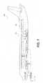
FIG. 1 is a schematic illustration of an aircraft, comprising a system for decontaminating an aircraft cabin and providing an indication that the aircraft cabin is safe for reentry, in accordance with some examples. -
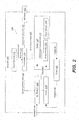
FIG. 2 is a block diagram of the aircraft inFIG. 1 , illustrating various components of the the system for decontaminating the aircraft cabin and providing an indication that the aircraft cabin is safe for reentry, in accordance with some examples. -
FIG. 3 is a block diagram of a controller of the system for decontaminating the aircraft cabin and providing an indication that the aircraft cabin is safe for reentry, illustrating various inputs and outputs of the controller, in accordance with some examples. -
FIG. 4 is a process flowchart of a method for decontaminating the aircraft cabin and providing an indication that the aircraft cabin is safe for reentry, in accordance with some examples. -
FIG. 5 illustrates plots of a remaining air fraction as a function of time for two different flowrates. -
FIG. 6 is a process flowchart corresponding to a method for manufacturing and servicing the aircraft. -
FIG. 7 illustrates a block diagram of an example aircraft, in accordance with some examples. - In the following description, numerous specific details are set forth in order to provide a thorough understanding of the presented concepts. In some examples, the presented concepts are practiced without some or all of these specific details. In other instances, well known process operations have not been described in detail so as to not unnecessarily obscure the described concepts. While some concepts will be described in conjunction with the specific examples, it will be understood that these examples are not intended to be limiting.
- Described herein are systems and methods for decontaminating aircraft cabins and for external identification of the decontamination process completion (e.g., when an aircraft cabin is free from infectious agents/diseases). In some examples, these systems and methods at least partially rely on existing environmental control systems (ECS) of aircraft, while providing new indication features to various users (e.g., airlines, flight crew, maintenance, ground crew).
- For example, a decontamination system is activated when no personnel is present in the aircraft cabin and, in some examples, the doors are closed. A controller determines a required output of one or more air conditioning packs and one or more fans to deliver air into the cabin, defining the total incoming flowrate. In some examples, this total incoming flowrate is presented in terms of air changes per hour, with 1 air change per hour representing a flowrate corresponding to a volume of the aircraft divided by an hour. It should be noted that when an incoming air is flown into the cabin, this incoming air displaces the air, which is present in the cabin and which may include contaminants. Initially, the displaced air is primarily the original air in the cabin, which is the air prior to the system activation. As the decontamination proceeds forward, the original air represents a smaller fraction of the displaced air since the ratio of the original air in the cabin decreases. This fraction is referred to as a remaining air fraction. The decontamination process involves reaching a certain minimal level of the remaining air fraction by replacing the original air in the cabin. This minimal level of the remaining air fraction is selected, e.g., based on the type of contaminants, likelihood of contamination, and other like factors.
- The total incoming flowrate, the volume of the aircraft, and the desired level of the remaining air fraction is used by the controller to determine duration of the decontamination process. In some examples, additional inputs to the controller (e.g., from one or more biosensors positioned in the aircraft cabin) are used to determine the duration (e.g., extend the decontamination process if the contaminants are still present above the allowable level).
- Upon completion of the decontamination process, the controller provides input to an external indicator (e.g., positioned outside the cabin) that the decontamination process is completed and that the cabin is safe to enter. It should be noted that, in some examples, entering the aircraft cabin during the decontamination process interferes with decontamination process (e.g., alters the air circulation) and/or potentially unsafe to entering personnel (e.g., contaminants suspended in the air). In some examples, the external indicator is a light, positioned proximate to an aircraft door.
- In some examples, the system is initiated and controlled manually. For example, a switch at a flight deck is used to start the process. In some examples, the system is initiated and controlled automatically. For example, a door sensor is used to initiate the process, upon detecting that all doors are closed. In some examples, a biosensor is used to provide input to the controller (e.g., based on the level of contaminants in the cabin). Furthermore, in some examples, the biosensor checks the air of the newly cleaned/purged cabin to ensure that the timer and controller were effective in completely purging and cleaning the cabin air. In some examples, the controller is used to control the speed of the fans of the ECS system for high flow rate through the cabin, and thereby reduce turn time. New variable speed fans could replace fixed speed fans in the system to assist with such method of high rate flow.
-
FIG. 1 is a schematic illustration ofaircraft 190, comprisingsystem 100 fordecontaminating aircraft cabin 150 and providing an indication thataircraft cabin 150 is safe for reentry, in accordance with some examples.FIG. 2 is a block diagram ofaircraft 190 inFIG. 1 , illustrating various components of thecomprising system 100. - Referring to
FIGS. 1 and2 ,system 100 comprises one or moreair conditioning packs 130, configured to receive ambient air fromoutside aircraft 190 and to supply ambient air intocabin 150 ofaircraft 190.System 100 also comprises one ormore filters 142 and one ormore fans 140, configured to receive cabin air fromcabin 150 ofaircraft 190, to pass cabin air through one ormore filters 142 thereby generating filtered air, and to supply filtered air intocabin 150. In some examples, one or moreair conditioning packs 130, one ormore fans 140, and one ormore filters 142 are parts of the ECS ofaircraft 190. In other words, one or moreair conditioning packs 130, one ormore fans 140, and one ormore filters 142 are also used during other operations ofaircraft 190, such as during the flight. -
System 100 also comprisescontroller 110, communicatively coupled to one or moreair conditioning packs 130 and to one ormore fans 140.System 100 is configured to receivedecontamination request 122 and to determineoperating parameters 112 of one or moreair conditioning packs 130 and one ormore fans 140 to perform the decontamination ofaircraft cabin 150. Various types ofoperating parameters 112 are within the scope. For example,operating parameters 112 comprise the duration of operating one or moreair conditioning packs 130 and one ormore fans 140. In some examples, the duration of operating one or moreair conditioning packs 130 is the same as the duration of operating one ormore fans 140. Alternatively, the duration of operating one or moreair conditioning packs 130 is different from the duration of operating one ormore fans 140. For example, the duration of operating one or moreair conditioning packs 130 is longer from the duration of operating one ormore fans 140. In another example, the duration of operating one or moreair conditioning packs 130 is shorter from the duration of operating one ormore fans 140. In some examples, the periods of operating one or moreair conditioning packs 130 and operating one ormore fans 140 coincide. Alternatively, the periods of operating one or moreair conditioning packs 130 and operating one ormore fans 140 are staggered. For example, the process starts with operating one or more air conditioning packs 130 only, while one ormore fans 140 are turned on lately. Alternatively, the process starts with operating one ormore fans 140 only, while one or more air conditioning packs 130 are turned on lately. - In some examples, the duration of operating one or more air conditioning packs 130 and one or
more fans 140 is determined based on one or more of (a) the cabin volume, (b) a combined ventilation rate provided by one or more air conditioning packs 130 and one ormore fans 140, and (c) an acceptable fraction of the remaining air inaircraft 190. This determination is further described below with reference toFIGS. 4 and5 below. In general, a larger cabin volume requires longer decontamination, and vice versa. A smaller combined ventilation rate requires longer decontamination, and vice versa. A lower acceptable fraction of the remaining air requires longer decontamination, and vice versa. -
System 100 also comprisesindicator 128, communicatively coupled tocontroller 110 and configured to receivecompletion indication 126 fromcontroller 110 and present tocompletion indication 126 toindicator 128 to indicate that cabin is safe for reentry. In some examples,completion indicator 128 is located on outside ofaircraft 190 and visible to persons outsideaircraft 190. For example,completion indicator 128 is located on one or more of a jet bridge, a jet bay, or an airport gate. In some examples,completion indicator 128 comprises or is coupled to a wireless transmitter, e.g., to inform remote users and systems about completion of decontamination process. For example, the departing time of a flight is conditioned on the completion of the decontamination process. - In some examples,
system 100 further comprisesinput device 120, communicatively coupled tocontroller 110 and configured to senddecontamination request 122 tocontroller 110. For example,input device 120 is one of a flight deck switch or an attendant panel. However, other examples within the scope. - In some examples,
system 100 further comprises one ormore biosensors 152, positioned withincabin 150 ofaircraft 190. One ormore biosensors 152 are configured to measure the presence or, more specifically, the concentration of one or more contaminants incabin 150. One ormore biosensors 152 are communicatively coupled tocontroller 110 and configured to providecontamination concentration input 153 tocontroller 110. In these examples,controller 110 is configured to usecontamination concentration input 153 to trigger operation of one or more air conditioning packs 130 and one ormore fans 140. For example, one ormore biosensors 152 determined the concentration of a contaminant exceeding a certain threshold and informscontroller 110 about the event. This part of the process is performed at any time. In some embodiments, one ormore biosensors 152 continuously monitor contaminants incabin 150. Upon receivingcontamination concentration input 153 from one ormore biosensors 152,controller 110 schedules a decontamination process, which may or may not occur immediately. For example,cabin 150 is still occupied when the contamination even was detected, in which case the decontamination process is scheduled for a future, e.g., whencabin 150 is free from occupants. - In some examples,
controller 110 is configured to usecontamination concentration input 153 to reviseoperating parameters 112 of one or more air conditioning packs 130 and one ormore fans 140. For example, the initially determined duration of operating one or more air conditioning packs 130 and one ormore fans 140 is revised based on contamination concentration input 153 (e.g., shortened ifcontamination concentration input 153 indicates a faster decay of the contaminant concentration, or lengthened ifcontamination concentration input 153 indicates a slower decay of the contaminant concentration). - In some examples, operating
parameters 112 further comprise operating output of each of one or more air conditioning packs 130 and each of one ormore fans 140. It should be noted that a combined ventilation rate is based on the ventilation rate one or more air conditioning packs 130 and the ventilation rate of each of one ormore fans 140. In some examples, the ratio of the ventilation rate one or more air conditioning packs 130 to the ventilation rate of each of one ormore fans 140 is 50%/50%. In some examples, this ratio is in the range of 10%/90% to 90%/10%. The ratio is selected, e.g., based on conditions of one ormore filters 142, outside weather conditions (e.g., temperature, humidity), and the like. - In some examples,
system 100 further comprises one ormore door sensors 154, positioned at each cabin door. One ormore door sensors 154 are configured to determine whether each cabin door is close or open. It should be noted that the decontamination process has different efficiencies depending on the position of the cabin doors. Furthermore, closing doors helps to control the spread of contaminants. In some examples, the decontamination process is initiated only when all doors are closed. - One or
more door sensors 154 are communicatively coupled tocontroller 110 and configured to providedoor closure input 157 tocontroller 110.Controller 110 is configured to operate one or more air conditioning packs 130 and one ormore fans 140 is initiated based ondoor closure input 157. For examples,controller 110 delays this operation until all cabin doors are closed. In some examples, the process proceeds when one or more doors remain open. In some operatingparameters 112 of one or more air conditioning packs 130 and one ormore fans 140 are further determined based ondoor closure input 157. For example, if one or more doors are open, then a higher combined ventilation rate is used. -
FIG. 3 illustrates various inputs and outputs tocontroller 110. For example,controller 110 receives (or stores) the cabin volume information, which is used for determining (e.g., calculating) operatingparameters 112, such asoperating duration 113. In the same or other examples,controller 110 receives (or stores) the combined ventilation rate, which is also used for determiningoperating parameters 112, such asoperating duration 113. In the same or other examples,controller 110 receives (or stores) the remaining air threshold, which is also used for determiningoperating parameters 112, such asoperating duration 113. Other examples of controller inputs include a decontamination request, a contaminant concentration, a door closure input. The controller used this information to determineoperating parameters 112, which are passed to one or more air conditioning packs 130 and one ormore fans 140 during execution of the decontamination process. Furthermore,controller 110 generatescompletion indicator 126, which is passed to, e.g.,indicator 128. -
FIG. 4 is a process flowchart ofmethod 400 for decontaminatingaircraft cabin 150 and providing an indication thataircraft cabin 150 is safe for reentry, in accordance with some examples. Various operations ofmethod 400 are performed usingsystem 100, which is described above with reference toFIGS. 1-3 . -
Method 400 comprises receiving (block 410)decontamination request 122 atcontroller 110. For example,input device 120 sendsdecontamination request 122 tocontroller 110, e.g., based on identification of the contamination event inaircraft cabin 150. Various examples of identifying the contamination event are within the scope, e.g., a passenger developing or reporting symptoms, receiving an external report based on a passenger manifest, receiving an input from one ormore biosensors 152, and the like. For example,decontamination request 122 is received from aninput device 120, communicatively coupled tocontroller 110, whereininput device 120 is one of a flight deck switch or an attendant panel. In another example,decontamination request 122 is received from one ormore biosensors 152, positioned withincabin 150 ofaircraft 190. More specifically,decontamination request 122 comprisescontaminant concentration input 153, exceeding a set threshold. -
Method 400 comprises determining (block 420), atcontroller 110, operatingparameters 112 of one or more air conditioning packs 130 and one ormore fans 140 ofaircraft 190.Operating parameters 112 comprise at least duration of operating one or more air conditioning packs 130 and one ormore fans 140. Other examples of operating parameters include operating output (e.g., a ventilation rate) of each of one or more air conditioning packs 130 and each of one ormore fans 140, sequence of operating one or more air conditioning packs 130 and one ormore fans 140, and the like. The duration of operating one or more air conditioning packs 130 and one ormore fans 140 is determined based on at least (a) the cabin volume ofaircraft 190, (b) a combined ventilation rate provided by air conditioning packs 130 and one ormore fans 140, and (c) a remaining air threshold inaircraft 190. The remaining air threshold reflects the concentration of the remaining contaminant in aircraft cabin. -
FIG. 5 illustrates plots of a remaining air fraction as a function of time for two different flowrates. Specifically,line 500 corresponds to a flowrate of 20 air-changes per hour, whileline 510 corresponds to a flowrate of 30 air-changes per hour.Line 520 represents an example of a remaining air fraction threshold, set at 10% in this example. With the flowrate of 20 air-changes per hour, the threshold is reached within about 7 minutes. With the flowrate of 30 air-changes per hour, the threshold is reached within about 4 minutes. The threshold depends on the type of contaminants and other like parameters. -
Method 400 proceeds with operating (block 430) one or more air conditioning packs 130 and one ormore fans 140 in accordance with operating parameters thereby decontaminatingcabin 150. In some examples, the operating output (e.g., a ventilation rate) of each one or more air conditioning packs 130 and each of one ormore fans 140 varies while operating (block 430) one or more air conditioning packs 130 and one ormore fans 140. - In some examples, the operation of one or more air conditioning packs 130 and one or
more fans 140 is performed whileaircraft 190 is grounded. Furthermore, in some examples, this operation is performed whileaircraft 190 is empty and free of occupants (decision block 426 inFIG. 4 ). For purposes of this disclosure, the term "occupant" is defined as a human or animal, capable of carrying a contaminant on board ofaircraft 190. - If the cabin is not empty,
method 400 proceeds with vacating (block 428) the occupants fromaircraft cabin 150. In some examples,method 400 further comprises confirming (block 424) thatcabin 150 ofaircraft 190 is empty and free of occupants before performing operating (block 430) one or more air conditioning packs 130 and one ormore fans 140. -
Method 400 proceeds with providing (block 440)completion indication 126 toindicator 128 uponcompletion decontaminating cabin 150. For example,completion indicator 128 is located on outside ofaircraft 190 and visible to persons outsideaircraft 190. More specifically,completion indicator 128 is located on one or more of a jet bridge, a jet bay, or an airport gate. In some examples,completion indicator 128 comprises or is coupled to a wireless transmitter. - In some examples,
method 400 further comprises receiving (block 450)contaminant concentration 153 incabin 150.Contaminant concentration 153 is received atcontroller 110 and from one ormore biosensors 152 positioned in acabin 150 ofaircraft 190. Furthermore,contaminant concentration 153 is received while operating (block 430) one or more air conditioning packs 130 and one ormore fans 140. For example, one ormore biosensors 152 continuously monitor concentration of the contaminants during the decontamination process.Method 400 continues with revising (block 422) operatingparameters 112 based oncontaminant concentration 153 incabin 150. - In some examples,
method 400 further comprises receiving (460), atcontroller 110 and from one ormore door sensors 154,door closure input 157, corresponding to an open-close position of each cabin door. In more specific examples, the operation of one or more air conditioning packs 130 and one or more fans 140 (block 430) is initiated or conditioned based on door closure input 157 (referring to decision block 426 inFIG. 4 ). - In some examples, operating
parameters 112 of one or more air conditioning packs 130 and one ormore fans 140 are further determined based ondoor closure input 157. - In some examples, methods and systems described above are used on aircraft and, more generally, by the aerospace industry. Specifically, these methods and systems can be used during fabrication of aircraft as well as during aircraft service and maintenance.
- Accordingly, the apparatus and methods described above are applicable for aircraft manufacturing and
service method 900 as shown inFIG. 6 and foraircraft 902 as shown inFIG. 7 . During pre-production,method 900 includes specification anddesign 904 ofaircraft 902 andmaterial procurement 906. During production, component andsubassembly manufacturing 908 andsystem integration 910 ofaircraft 902 takes place. Thereafter,aircraft 902 goes through certification anddelivery 912 in order to be placed inservice 914. While in service by a customer,aircraft 902 is scheduled for routine maintenance andservice 916, which also includes modification, reconfiguration, refurbishment, and so on. - In some examples, each of the processes of
method 900 is performed or carried out by a system integrator, a third party, and/or an operator, e.g., a customer. For the purposes of this description, a system integrator includes without limitation any number of aircraft manufacturers and major-system subcontractors; a third party includes without limitation any number of venders, subcontractors, and suppliers; and an operator can be an airline, leasing company, military entity, service organization, and so on. - As shown in
FIG. 7 ,aircraft 902 produced bymethod 900 includesairframe 918 with plurality ofsystems 920 and interior 922. Theairframe 918 includes wings of theaircraft 902. Examples ofsystems 920 include one or more of propulsion system 924,electrical system 926,hydraulic system 928, andenvironmental system 930. Any number of other systems can be included. - Apparatus and methods presented herein can be employed during any one or more of the stages of
method 900. For example, components or subassemblies corresponding to manufacturing 908 are fabricated or manufactured in a manner similar to components or subassemblies produced whileaircraft 902 is in service. Also, one or more apparatus examples, method examples, or a combination thereof are utilized duringmanufacturing 908 andsystem integration 910, for example, by substantially expediting assembly of or reducing the cost of anaircraft 902. Similarly, one or more of apparatus examples, method examples, or a combination thereof are utilized whileaircraft 902 is in service, for example and without limitation, to maintenance andservice 916. - Further, the disclosure comprises embodiments according to the following clauses:
- 1. A method (400) for decontaminating a cabin (150) of an aircraft (190) and providing an indication that the cabin (150) is safe for reentry, the method (400) comprising:
- receiving (410) a decontamination request (122) at a controller (110);
- determining (420), at the controller (110), operating parameters (112) of one or more air conditioning packs (130) and one or more fans (140) of the aircraft (190),
wherein the operating parameters (112) comprise at least a duration of operating the one or more air conditioning packs (130) and the one or more fans (140), and
wherein the duration of operating the one or more air conditioning packs (130) and the one or more fans (140) is determined based on at least a cabin volume of the aircraft (190), a combined ventilation rate provided by the air conditioning packs (130) and the one or more fans (140), and a remaining air threshold in the aircraft (190); - operating (430) the one or more air conditioning packs (130) and the one or more fans (140) in accordance with the operating parameters thereby decontaminating the cabin (150); and
- providing (440) a completion indication (126) to an indicator (128) upon completion decontaminating the cabin (150).
- 2. The method (400) of
clause 1, wherein the decontamination request (122) is received from an input device (120), communicatively coupled to the controller (110), wherein the input device (120) is one of a flight deck switch or an attendant panel. - 3. The method (400) of
clauses 1 or 2, wherein the decontamination request (122) is received from one or more biosensors (152), positioned within a cabin (150) of the aircraft (190). - 4. The method (400) of clause 3, wherein the decontamination request (122) comprises a contaminant concentration input (153), exceeding a set threshold.
- 5. The method (400) of any of
clauses 1 to 4, wherein the operating parameters (112) further comprise operating output of each of the one or more air conditioning packs (130) and each of the one or more fans (140). - 6. The method (400) of
clause 5, wherein the operating output of each the one or more air conditioning packs (130) and each of the one or more fans (140) varies while operating (430) the one or more air conditioning packs (130) and the one or more fans (140). - 7. The method (400) of any of
clauses 1 to 6, further comprising:- receiving (450), at the controller (110) and from one or more biosensors (152) positioned in a cabin (150) of the aircraft (190) and while operating (430) the one or more air conditioning packs (130) and the one or more fans (140), contaminant concentration (153) in the cabin (150); and
- revising (422) the operating parameters (112) based on the contaminant concentration (153) in the cabin (150).
- 8. The method (400) of any of
clauses 1 to 7, further comprising receiving, at the controller (110) and from one or more door sensors (154), a door closure input (157), corresponding to an open-close position of each cabin door. - 9. The method (400) of clause 8, wherein operating (430) the one or more air conditioning packs (130) and the one or more fans (140) is initiated based on the door closure input (157).
- 10. The method (400) of clause 8, wherein the operating parameters (112) of the one or more air conditioning packs (130) and the one or more fans (140) are further determined based on the door closure input (157).
- 11. The method (400) of any of
clauses 1 to 10, wherein the completion indicator (128) is located on the outside of theaircraft 190 and visible to persons outside the aircraft (190). - 12. The method (400) of any of
clauses 1 to 11, wherein the completion indicator (128) is located on one or more of a jet bridge, a jet bay, or an airport gate, and visible to persons outside the aircraft (190). - 13. The method (400) of any of
clauses 1 to 12, wherein the completion indicator (128) comprises or is coupled to a wireless transmitter. - 14. The method (400) of any of
clauses 1 to 13, wherein at least operating (430) the one or more air conditioning packs (130) and the one or more fans (140) is performed while the aircraft (190) is grounded. - 15. The method (400) of any of
clauses 1 to 14, wherein at least operating (430) the one or more air conditioning packs (130) and the one or more fans (140) is performed when the cabin (150) of the aircraft (190) is empty and free of occupants. - 16. The method (400) of any of
clauses 1 to 15, further comprising confirming that the cabin (150) of the aircraft (190) is empty and free of occupants before performing operating (430) the one or more air conditioning packs (130) and the one or more fans (140). - 17. A system (100) for decontaminating a cabin (150) of an aircraft (190) and providing an indication that the cabin (150) is safe for reentry, the system (100) comprising:
- one or more air conditioning packs (130), configured to receive ambient air from outside the aircraft (190) and to supply the ambient air into the cabin (150) of the aircraft (190);
- one or more filters (142);
- one or more fans (140), configured to receive cabin air from the cabin (150) of the aircraft (190), to pass the cabin air through the one or more filters (142) thereby generating filtered air, and to supply the filtered air into the cabin (150);
- a controller (110), communicatively coupled to the one or more air conditioning packs (130) and to the one or more fans (140) and configured to receive a decontamination request (122) and to determine operating parameters (112) of one or more air conditioning packs (130) and one or more fans (140) to perform decontamination,
wherein the operating parameters (112) comprise duration of operating the one or more air conditioning packs (130) and the one or more fans (140), and
wherein the duration of operating the one or more air conditioning packs (130) and the one or more fans (140) is determined based on one or more of (a) a cabin volume of the aircraft (190), (b) a combined ventilation rate provided by the one or more air conditioning packs (130) and the one or more fans (140), and (c) an acceptable fraction of remaining air in the aircraft (190); and - an indicator (128), communicatively coupled to the controller (110) and configured to receive completion indication (126) from the controller (110) and present to the completion indication (126) to the indicator (128) to indicate that the cabin is safe for reentry.
- 18. The system (100) of clause 17, further comprising an input device (120), communicatively coupled to the controller (110) and configured to send a decontamination request (122) to the controller (110), wherein the input device (120) is one of a flight deck switch or an attendant panel.
- 19. The system (100) of any of clauses 17 or 18, further comprising one or more biosensors (152), positioned within the cabin (150) of the aircraft (190), communicatively coupled to the controller (110), and configured to provide contamination concentration input (153) to the controller (110).
- 20. The system (100) of clause 19, wherein the controller (110) is configured to use the contamination concentration input (153) to trigger operation of the one or more air conditioning packs (130) and the one or more fans (140).
- 21. The system (100) of clause 19, wherein the controller (110) is configured to use the contamination concentration input (153) to revise the operating parameters (112) of the one or more air conditioning packs (130) and the one or more fans (140).
- 22. The system (100) of any of clauses 17 to 21, wherein the operating parameters (112) further comprise operating output of each of the one or more air conditioning packs (130) and each of the one or more fans (140).
- 23. The system (100) of any of clauses 17 to 22, further comprising one or more door sensors (154), positioned at each cabin door, communicatively coupled to the controller (110), and configured to provide door closure input (157), corresponding to an open-close position of each cabin door, to the controller (110).
- 24. The system (100) of clause 23, wherein the controller (110) is configured to operate the one or more air conditioning packs (130) and the one or more fans (140) is initiated based on the door closure input (157).
- 25. The system (100) of clause 23, wherein the operating parameters (112) of the one or more air conditioning packs (130) and the one or more fans (140) are further determined based on the door closure input (157).
- 26. The system (100) of any of clauses 17 to 25, wherein the completion indicator (128) is located on the outside of the
aircraft 190 and visible to persons outside the aircraft (190). - 27. The system (100) of any of clauses 17 to 26, wherein the completion indicator (128) is located on one or more of a jet bridge, a jet bay, or an airport gate, and visible to persons outside the aircraft (190).
- 28. The system (100) of any of clauses 17 to 27, wherein the completion indicator (128) comprises or is coupled to a wireless transmitter.
- Although the foregoing concepts have been described in some detail for purposes of clarity of understanding, it will be apparent that certain changes and modifications may be practiced within the scope of the appended claims. It should be noted that there are many alternative ways of implementing the processes, systems, and apparatus. Accordingly, the present examples are to be considered as illustrative and not restrictive.
Claims (15)
- A method (400) for decontaminating a cabin (150) of an aircraft (190) and providing an indication that the cabin (150) is safe for reentry, the method (400) comprising:receiving (410) a decontamination request (122) at a controller (110);determining (420), at the controller (110), operating parameters (112) of one or more air conditioning packs (130) and one or more fans (140) of the aircraft (190),
wherein the operating parameters (112) comprise at least a duration of operating the one or more air conditioning packs (130) and the one or more fans (140), and
wherein the duration of operating the one or more air conditioning packs (130) and the one or more fans (140) is determined based on at least a cabin volume of the aircraft (190), a combined ventilation rate provided by the air conditioning packs (130) and the one or more fans (140), and a remaining air threshold in the aircraft (190);operating (430) the one or more air conditioning packs (130) and the one or more fans (140) in accordance with the operating parameters thereby decontaminating the cabin (150); andproviding (440) a completion indication (126) to an indicator (128) upon completion decontaminating the cabin (150). - The method (400) of claim 1, wherein the decontamination request (122) is received from an input device (120), communicatively coupled to the controller (110), wherein the input device (120) is one of a flight deck switch or an attendant panel.
- The method (400) of claims 1 or 2, wherein the decontamination request (122) is received from one or more biosensors (152), positioned within a cabin (150) of the aircraft (190).
- The method (400) of claim 3, wherein the decontamination request (122) comprises a contaminant concentration input (153), exceeding a set threshold.
- The method (400) of any of claims 1 to 4, wherein the operating parameters (112) further comprise operating output of each of the one or more air conditioning packs (130) and each of the one or more fans (140).
- The method (400) of claim 5, wherein the operating output of each the one or more air conditioning packs (130) and each of the one or more fans (140) varies while operating (430) the one or more air conditioning packs (130) and the one or more fans (140).
- The method (400) of any of claims 1 to 6, further comprising:receiving (450), at the controller (110) and from one or more biosensors (152) positioned in a cabin (150) of the aircraft (190) and while operating (430) the one or more air conditioning packs (130) and the one or more fans (140), contaminant concentration (153) in the cabin (150); andrevising (422) the operating parameters (112) based on the contaminant concentration (153) in the cabin (150).
- The method (400) of any of claims 1 to 7, further comprising receiving, at the controller (110) and from one or more door sensors (154), a door closure input (157), corresponding to an open-close position of each cabin door.
- The method (400) of claim 8, wherein operating (430) the one or more air conditioning packs (130) and the one or more fans (140) is initiated based on the door closure input (157).
- The method (400) of claim 8, wherein the operating parameters (112) of the one or more air conditioning packs (130) and the one or more fans (140) are further determined based on the door closure input (157).
- The method (400) of any of claims 1 to 10, wherein the completion indicator (128) is located on the outside of the aircraft 190 and visible to persons outside the aircraft (190).
- The method (400) of any of claims 1 to 11, wherein the completion indicator (128) comprises or is coupled to a wireless transmitter.
- The method (400) of any of claims 1 to 12, wherein at least operating (430) the one or more air conditioning packs (130) and the one or more fans (140) is performed while the aircraft (190) is grounded, empty and free of occupants.
- A system (100) for decontaminating a cabin (150) of an aircraft (190) and providing an indication that the cabin (150) is safe for reentry, the system (100) comprising:one or more air conditioning packs (130), configured to receive ambient air from outside the aircraft (190) and to supply the ambient air into the cabin (150) of the aircraft (190);one or more filters (142);one or more fans (140), configured to receive cabin air from the cabin (150) of the aircraft (190), to pass the cabin air through the one or more filters (142) thereby generating filtered air, and to supply the filtered air into the cabin (150);a controller (110), communicatively coupled to the one or more air conditioning packs (130) and to the one or more fans (140) and configured to receive a decontamination request (122) and to determine operating parameters (112) of one or more air conditioning packs (130) and one or more fans (140) to perform decontamination,
wherein the operating parameters (112) comprise duration of operating the one or more air conditioning packs (130) and the one or more fans (140), and
wherein the duration of operating the one or more air conditioning packs (130) and the one or more fans (140) is determined based on one or more of (a) a cabin volume of the aircraft (190), (b) a combined ventilation rate provided by the one or more air conditioning packs (130) and the one or more fans (140), and (c) an acceptable fraction of remaining air in the aircraft (190); andan indicator (128), communicatively coupled to the controller (110) and configured to receive completion indication (126) from the controller (110) and present to the completion indication (126) to the indicator (128) to indicate that the cabin is safe for reentry. - The system (100) of claim 14, further comprising an input device (120), communicatively coupled to the controller (110) and configured to send a decontamination request (122) to the controller (110), wherein the input device (120) is one of a flight deck switch or an attendant panel.
Applications Claiming Priority (2)
| Application Number | Priority Date | Filing Date | Title |
|---|---|---|---|
| US202063041620P | 2020-06-19 | 2020-06-19 | |
| US17/349,224 US12179926B2 (en) | 2020-06-19 | 2021-06-16 | Methods and systems for decontaminating aircraft cabins and providing indications for safe reentry |
Publications (2)
| Publication Number | Publication Date |
|---|---|
| EP3925886A1 true EP3925886A1 (en) | 2021-12-22 |
| EP3925886B1 EP3925886B1 (en) | 2024-08-07 |
Family
ID=76829279
Family Applications (1)
| Application Number | Title | Priority Date | Filing Date |
|---|---|---|---|
| EP21180338.2A Active EP3925886B1 (en) | 2020-06-19 | 2021-06-18 | Methods and systems for decontaminating aircraft cabins and providing indications for safe reentry |
Country Status (4)
| Country | Link |
|---|---|
| US (1) | US12179926B2 (en) |
| EP (1) | EP3925886B1 (en) |
| JP (1) | JP7726679B2 (en) |
| CN (1) | CN113815868B (en) |
Citations (5)
| Publication number | Priority date | Publication date | Assignee | Title |
|---|---|---|---|---|
| US4742761A (en) * | 1987-07-20 | 1988-05-10 | The Boeing Company | Method and apparatus for controlling the concentration of carbon dioxide in an aircraft cabin |
| US20090311138A1 (en) * | 2006-01-31 | 2009-12-17 | Peter Klaptchuk | Sanitization of aircraft or vehicle cabin |
| EP3050801A1 (en) * | 2015-01-27 | 2016-08-03 | Honeywell International Inc. | Aircraft environmental control system that optimizes the proportion of outside air from engines, apu's, ground air sources and the recirculated cabin air to maintain occupant comfort and maximize fuel economy |
| EP3050803A1 (en) * | 2015-01-27 | 2016-08-03 | Honeywell International Inc. | Human factors approach to control contaminant concentrations in aircraft supply air from engine and apu bleed air and ground air sources, and in recirculated air being delivered to aircraft cabins for the optimization of user experience and energy consumption |
| WO2016189420A1 (en) * | 2015-05-22 | 2016-12-01 | Bombardier Inc. | Aircraft air quality monitoring system and method |
Family Cites Families (29)
| Publication number | Priority date | Publication date | Assignee | Title |
|---|---|---|---|---|
| US6668563B2 (en) * | 2002-02-09 | 2003-12-30 | Bernard J. Mirowsky | Air treatment system for airplanes |
| US7121100B2 (en) * | 2003-09-09 | 2006-10-17 | The Boeing Company | High efficiency aircraft cabin air supply cooling system |
| US20050074359A1 (en) * | 2003-10-06 | 2005-04-07 | Steris Inc. | Aircraft and passenger decontamination system |
| US7871038B2 (en) * | 2007-05-17 | 2011-01-18 | The Boeing Company | Systems and methods for providing airflow in an aerospace vehicle |
| US10029797B2 (en) * | 2008-09-30 | 2018-07-24 | The Boeing Company | Personal ventilation in an aircraft environment |
| JP2012066755A (en) * | 2010-09-27 | 2012-04-05 | Panasonic Corp | Airplane with deodorizing and disinfecting functions |
| DE102011007351A1 (en) * | 2011-04-14 | 2012-10-18 | Ford Global Technologies, Llc | Method and device for improving the air in a vehicle interior |
| US9889939B2 (en) * | 2012-06-06 | 2018-02-13 | The Boeing Company | Environmental control system and methods of operating same |
| US10195298B2 (en) * | 2013-02-27 | 2019-02-05 | Arthur Kreitenberg | Internal sanitizing and communicating |
| US8992830B2 (en) * | 2013-03-15 | 2015-03-31 | The Boeing Company | High temperature decontamination of aircraft compartments |
| US9440745B1 (en) * | 2013-07-12 | 2016-09-13 | The Boeing Company | Air distribution system for small commercial airplane |
| US9657590B2 (en) | 2014-08-04 | 2017-05-23 | Rolls-Royce Corporation | Aircraft engine cleaning system |
| DE112015004376T5 (en) * | 2014-09-26 | 2017-06-08 | Mag Aerospace Industries, Llc | Systems and methods for treating cabin surfaces and air |
| US9623133B2 (en) | 2015-01-30 | 2017-04-18 | The Boeing Company | Lavatory disinfection system |
| CN108025618A (en) * | 2015-08-03 | 2018-05-11 | 爱科国际有限公司 | System and method for the air for handling vehicle cab |
| US9884281B2 (en) * | 2015-09-18 | 2018-02-06 | Honeywell International Inc. | Method to use ultrafine particulate matter detection and measurement to control air supply system contaminant delivery to the aircraft cabin environment |
| US10414505B2 (en) * | 2016-09-02 | 2019-09-17 | Embraer S.A. | Aircraft air conditioning system airflow regulation |
| CA2992202C (en) * | 2017-01-27 | 2023-08-15 | The Boeing Company | Automated decontamination of complex areas |
| WO2018137003A2 (en) * | 2017-01-30 | 2018-08-02 | Национальная Академия Авиации | Method and apparatus for the sanitation of aircraft cabins |
| US10737791B2 (en) * | 2017-10-04 | 2020-08-11 | The Boeing Company | Aerospace vehicle environmental control system |
| WO2019227237A1 (en) * | 2018-06-01 | 2019-12-05 | 4031202 Canada Inc. | Air quality improvement for pressurized aircraft |
| CN208699060U (en) | 2018-06-13 | 2019-04-05 | 天津大学 | A kind of passenger plane cockpit return air purification system |
| JP6669845B1 (en) | 2018-12-25 | 2020-03-18 | 日機装株式会社 | Infection control device |
| JP7251975B2 (en) * | 2018-12-27 | 2023-04-04 | 川崎重工業株式会社 | Skin cooling system |
| US12226554B2 (en) * | 2020-06-19 | 2025-02-18 | The Boeing Company | System and method for disinfecting an interior of an aircraft |
| US11780590B2 (en) * | 2020-08-14 | 2023-10-10 | Honeywell International Inc. | Aircraft cabin disinfection |
| US12201932B2 (en) * | 2020-10-16 | 2025-01-21 | Adam R. Skelton | Air purification system for passenger transport cabin |
| US11999492B2 (en) * | 2022-05-19 | 2024-06-04 | Textron Innovations Inc. | Electric temperature control system for unpressurized aircraft |
| US11780593B1 (en) * | 2022-08-04 | 2023-10-10 | Greg Longe | Aircraft cabin air conditioning system |
-
2021
- 2021-06-16 US US17/349,224 patent/US12179926B2/en active Active
- 2021-06-18 JP JP2021101986A patent/JP7726679B2/en active Active
- 2021-06-18 EP EP21180338.2A patent/EP3925886B1/en active Active
- 2021-06-21 CN CN202110686083.4A patent/CN113815868B/en active Active
Patent Citations (5)
| Publication number | Priority date | Publication date | Assignee | Title |
|---|---|---|---|---|
| US4742761A (en) * | 1987-07-20 | 1988-05-10 | The Boeing Company | Method and apparatus for controlling the concentration of carbon dioxide in an aircraft cabin |
| US20090311138A1 (en) * | 2006-01-31 | 2009-12-17 | Peter Klaptchuk | Sanitization of aircraft or vehicle cabin |
| EP3050801A1 (en) * | 2015-01-27 | 2016-08-03 | Honeywell International Inc. | Aircraft environmental control system that optimizes the proportion of outside air from engines, apu's, ground air sources and the recirculated cabin air to maintain occupant comfort and maximize fuel economy |
| EP3050803A1 (en) * | 2015-01-27 | 2016-08-03 | Honeywell International Inc. | Human factors approach to control contaminant concentrations in aircraft supply air from engine and apu bleed air and ground air sources, and in recirculated air being delivered to aircraft cabins for the optimization of user experience and energy consumption |
| WO2016189420A1 (en) * | 2015-05-22 | 2016-12-01 | Bombardier Inc. | Aircraft air quality monitoring system and method |
Also Published As
| Publication number | Publication date |
|---|---|
| CN113815868A (en) | 2021-12-21 |
| US20210394911A1 (en) | 2021-12-23 |
| JP7726679B2 (en) | 2025-08-20 |
| EP3925886B1 (en) | 2024-08-07 |
| US12179926B2 (en) | 2024-12-31 |
| JP2022002948A (en) | 2022-01-11 |
| CN113815868B (en) | 2025-09-05 |
Similar Documents
| Publication | Publication Date | Title |
|---|---|---|
| EP2796956B1 (en) | Aircraft performance monitoring system | |
| Graydon et al. | Guidance for designing safety into urban air mobility: Hazard analysis techniques | |
| US9957052B2 (en) | Aircraft environmental control system that optimizes the proportion of outside air from engines, APU's, ground air sources and the recirculated cabin air to maintain occupant comfort and maximize fuel economy | |
| CN112009700B (en) | Aircraft turnaround monitoring system and method | |
| CA2898543C (en) | Method and system to enable selective smoke detection sensitivity | |
| US20050010460A1 (en) | Facilities control system and method of controlling facilities | |
| Samad | Human‐in‐the‐loop control and cyber–physical–human systems: applications and categorization | |
| EP2572985B1 (en) | Dual boarding method and system for aircraft | |
| EP3786752A1 (en) | Automated aircraft system with goal driven action planning | |
| JP7763648B2 (en) | Computerized airport and cabin systems to avoid touchpoints and maintain social distancing | |
| EP3882145B1 (en) | Thermal container for the transport of temperature-controlled material | |
| KR101548918B1 (en) | Osculating device for boarding bridge and osculating method thereof | |
| EP3578462B1 (en) | Artificially intelligent flight crew systems and methods | |
| EP3925886B1 (en) | Methods and systems for decontaminating aircraft cabins and providing indications for safe reentry | |
| Pritchett | Simultaneous design of cockpit display of traffic information and air traffic management procedures | |
| Thomas et al. | The Devil Between the Details: Limitations of Probability-Based Approaches to Human Error | |
| EP3296207B1 (en) | Method to use ultrafine particulate matter detection and measurement to control air supply system contaminant delivery to the aircraft cabin environment | |
| Meyer et al. | Safety level of airside, pre-take-off objects and processes | |
| US12304612B2 (en) | Automated cabin-divider door | |
| CN120278678B (en) | Method, device, equipment and medium for automatic approval of airport flight time adjustment | |
| Stoll | A System Safety Assessment of an Unmanned, Solar-Powered Stratospheric Aircraft Using the STPA Methodology | |
| Lechniak et al. | Manned versus unmanned risk and complexity considerations for future midsized X-planes | |
| Greco et al. | An innovative air accident investigation method to safety differently | |
| Zhang | Civil Aircraft Functional Reliability Requirements Capture and Decomposition | |
| Stichternath | Pilot Measures against Cabin Air Contamination |
Legal Events
| Date | Code | Title | Description |
|---|---|---|---|
| PUAI | Public reference made under article 153(3) epc to a published international application that has entered the european phase |
Free format text: ORIGINAL CODE: 0009012 |
|
| STAA | Information on the status of an ep patent application or granted ep patent |
Free format text: STATUS: THE APPLICATION HAS BEEN PUBLISHED |
|
| AK | Designated contracting states |
Kind code of ref document: A1 Designated state(s): AL AT BE BG CH CY CZ DE DK EE ES FI FR GB GR HR HU IE IS IT LI LT LU LV MC MK MT NL NO PL PT RO RS SE SI SK SM TR |
|
| B565 | Issuance of search results under rule 164(2) epc |
Effective date: 20211116 |
|
| STAA | Information on the status of an ep patent application or granted ep patent |
Free format text: STATUS: REQUEST FOR EXAMINATION WAS MADE |
|
| 17P | Request for examination filed |
Effective date: 20220621 |
|
| RBV | Designated contracting states (corrected) |
Designated state(s): AL AT BE BG CH CY CZ DE DK EE ES FI FR GB GR HR HU IE IS IT LI LT LU LV MC MK MT NL NO PL PT RO RS SE SI SK SM TR |
|
| RAP3 | Party data changed (applicant data changed or rights of an application transferred) |
Owner name: THE BOEING COMPANY |
|
| GRAP | Despatch of communication of intention to grant a patent |
Free format text: ORIGINAL CODE: EPIDOSNIGR1 |
|
| STAA | Information on the status of an ep patent application or granted ep patent |
Free format text: STATUS: GRANT OF PATENT IS INTENDED |
|
| INTG | Intention to grant announced |
Effective date: 20230411 |
|
| GRAJ | Information related to disapproval of communication of intention to grant by the applicant or resumption of examination proceedings by the epo deleted |
Free format text: ORIGINAL CODE: EPIDOSDIGR1 |
|
| STAA | Information on the status of an ep patent application or granted ep patent |
Free format text: STATUS: REQUEST FOR EXAMINATION WAS MADE |
|
| INTC | Intention to grant announced (deleted) | ||
| GRAP | Despatch of communication of intention to grant a patent |
Free format text: ORIGINAL CODE: EPIDOSNIGR1 |
|
| STAA | Information on the status of an ep patent application or granted ep patent |
Free format text: STATUS: GRANT OF PATENT IS INTENDED |
|
| INTG | Intention to grant announced |
Effective date: 20240319 |
|
| GRAS | Grant fee paid |
Free format text: ORIGINAL CODE: EPIDOSNIGR3 |
|
| GRAA | (expected) grant |
Free format text: ORIGINAL CODE: 0009210 |
|
| STAA | Information on the status of an ep patent application or granted ep patent |
Free format text: STATUS: THE PATENT HAS BEEN GRANTED |
|
| AK | Designated contracting states |
Kind code of ref document: B1 Designated state(s): AL AT BE BG CH CY CZ DE DK EE ES FI FR GB GR HR HU IE IS IT LI LT LU LV MC MK MT NL NO PL PT RO RS SE SI SK SM TR |
|
| REG | Reference to a national code |
Ref country code: GB Ref legal event code: FG4D |
|
| REG | Reference to a national code |
Ref country code: CH Ref legal event code: EP |
|
| P01 | Opt-out of the competence of the unified patent court (upc) registered |
Free format text: CASE NUMBER: APP_42811/2024 Effective date: 20240721 |
|
| REG | Reference to a national code |
Ref country code: IE Ref legal event code: FG4D |
|
| REG | Reference to a national code |
Ref country code: DE Ref legal event code: R096 Ref document number: 602021016696 Country of ref document: DE |
|
| REG | Reference to a national code |
Ref country code: LT Ref legal event code: MG9D |
|
| REG | Reference to a national code |
Ref country code: NL Ref legal event code: MP Effective date: 20240807 |
|
| PG25 | Lapsed in a contracting state [announced via postgrant information from national office to epo] |
Ref country code: NO Free format text: LAPSE BECAUSE OF FAILURE TO SUBMIT A TRANSLATION OF THE DESCRIPTION OR TO PAY THE FEE WITHIN THE PRESCRIBED TIME-LIMIT Effective date: 20241107 |
|
| REG | Reference to a national code |
Ref country code: AT Ref legal event code: MK05 Ref document number: 1710660 Country of ref document: AT Kind code of ref document: T Effective date: 20240807 |
|
| PG25 | Lapsed in a contracting state [announced via postgrant information from national office to epo] |
Ref country code: FI Free format text: LAPSE BECAUSE OF FAILURE TO SUBMIT A TRANSLATION OF THE DESCRIPTION OR TO PAY THE FEE WITHIN THE PRESCRIBED TIME-LIMIT Effective date: 20240807 Ref country code: NL Free format text: LAPSE BECAUSE OF FAILURE TO SUBMIT A TRANSLATION OF THE DESCRIPTION OR TO PAY THE FEE WITHIN THE PRESCRIBED TIME-LIMIT Effective date: 20240807 Ref country code: PT Free format text: LAPSE BECAUSE OF FAILURE TO SUBMIT A TRANSLATION OF THE DESCRIPTION OR TO PAY THE FEE WITHIN THE PRESCRIBED TIME-LIMIT Effective date: 20241209 Ref country code: PL Free format text: LAPSE BECAUSE OF FAILURE TO SUBMIT A TRANSLATION OF THE DESCRIPTION OR TO PAY THE FEE WITHIN THE PRESCRIBED TIME-LIMIT Effective date: 20240807 Ref country code: GR Free format text: LAPSE BECAUSE OF FAILURE TO SUBMIT A TRANSLATION OF THE DESCRIPTION OR TO PAY THE FEE WITHIN THE PRESCRIBED TIME-LIMIT Effective date: 20241108 |
|
| PG25 | Lapsed in a contracting state [announced via postgrant information from national office to epo] |
Ref country code: BG Free format text: LAPSE BECAUSE OF FAILURE TO SUBMIT A TRANSLATION OF THE DESCRIPTION OR TO PAY THE FEE WITHIN THE PRESCRIBED TIME-LIMIT Effective date: 20240807 |
|
| PG25 | Lapsed in a contracting state [announced via postgrant information from national office to epo] |
Ref country code: LV Free format text: LAPSE BECAUSE OF FAILURE TO SUBMIT A TRANSLATION OF THE DESCRIPTION OR TO PAY THE FEE WITHIN THE PRESCRIBED TIME-LIMIT Effective date: 20240807 |
|
| PG25 | Lapsed in a contracting state [announced via postgrant information from national office to epo] |
Ref country code: AT Free format text: LAPSE BECAUSE OF FAILURE TO SUBMIT A TRANSLATION OF THE DESCRIPTION OR TO PAY THE FEE WITHIN THE PRESCRIBED TIME-LIMIT Effective date: 20240807 Ref country code: IS Free format text: LAPSE BECAUSE OF FAILURE TO SUBMIT A TRANSLATION OF THE DESCRIPTION OR TO PAY THE FEE WITHIN THE PRESCRIBED TIME-LIMIT Effective date: 20241207 |
|
| PG25 | Lapsed in a contracting state [announced via postgrant information from national office to epo] |
Ref country code: HR Free format text: LAPSE BECAUSE OF FAILURE TO SUBMIT A TRANSLATION OF THE DESCRIPTION OR TO PAY THE FEE WITHIN THE PRESCRIBED TIME-LIMIT Effective date: 20240807 |
|
| PG25 | Lapsed in a contracting state [announced via postgrant information from national office to epo] |
Ref country code: RS Free format text: LAPSE BECAUSE OF FAILURE TO SUBMIT A TRANSLATION OF THE DESCRIPTION OR TO PAY THE FEE WITHIN THE PRESCRIBED TIME-LIMIT Effective date: 20241107 Ref country code: ES Free format text: LAPSE BECAUSE OF FAILURE TO SUBMIT A TRANSLATION OF THE DESCRIPTION OR TO PAY THE FEE WITHIN THE PRESCRIBED TIME-LIMIT Effective date: 20240807 |
|
| PG25 | Lapsed in a contracting state [announced via postgrant information from national office to epo] |
Ref country code: RS Free format text: LAPSE BECAUSE OF FAILURE TO SUBMIT A TRANSLATION OF THE DESCRIPTION OR TO PAY THE FEE WITHIN THE PRESCRIBED TIME-LIMIT Effective date: 20241107 Ref country code: PT Free format text: LAPSE BECAUSE OF FAILURE TO SUBMIT A TRANSLATION OF THE DESCRIPTION OR TO PAY THE FEE WITHIN THE PRESCRIBED TIME-LIMIT Effective date: 20241209 Ref country code: PL Free format text: LAPSE BECAUSE OF FAILURE TO SUBMIT A TRANSLATION OF THE DESCRIPTION OR TO PAY THE FEE WITHIN THE PRESCRIBED TIME-LIMIT Effective date: 20240807 Ref country code: NO Free format text: LAPSE BECAUSE OF FAILURE TO SUBMIT A TRANSLATION OF THE DESCRIPTION OR TO PAY THE FEE WITHIN THE PRESCRIBED TIME-LIMIT Effective date: 20241107 Ref country code: NL Free format text: LAPSE BECAUSE OF FAILURE TO SUBMIT A TRANSLATION OF THE DESCRIPTION OR TO PAY THE FEE WITHIN THE PRESCRIBED TIME-LIMIT Effective date: 20240807 Ref country code: LV Free format text: LAPSE BECAUSE OF FAILURE TO SUBMIT A TRANSLATION OF THE DESCRIPTION OR TO PAY THE FEE WITHIN THE PRESCRIBED TIME-LIMIT Effective date: 20240807 Ref country code: IS Free format text: LAPSE BECAUSE OF FAILURE TO SUBMIT A TRANSLATION OF THE DESCRIPTION OR TO PAY THE FEE WITHIN THE PRESCRIBED TIME-LIMIT Effective date: 20241207 Ref country code: HR Free format text: LAPSE BECAUSE OF FAILURE TO SUBMIT A TRANSLATION OF THE DESCRIPTION OR TO PAY THE FEE WITHIN THE PRESCRIBED TIME-LIMIT Effective date: 20240807 Ref country code: GR Free format text: LAPSE BECAUSE OF FAILURE TO SUBMIT A TRANSLATION OF THE DESCRIPTION OR TO PAY THE FEE WITHIN THE PRESCRIBED TIME-LIMIT Effective date: 20241108 Ref country code: FI Free format text: LAPSE BECAUSE OF FAILURE TO SUBMIT A TRANSLATION OF THE DESCRIPTION OR TO PAY THE FEE WITHIN THE PRESCRIBED TIME-LIMIT Effective date: 20240807 Ref country code: ES Free format text: LAPSE BECAUSE OF FAILURE TO SUBMIT A TRANSLATION OF THE DESCRIPTION OR TO PAY THE FEE WITHIN THE PRESCRIBED TIME-LIMIT Effective date: 20240807 Ref country code: BG Free format text: LAPSE BECAUSE OF FAILURE TO SUBMIT A TRANSLATION OF THE DESCRIPTION OR TO PAY THE FEE WITHIN THE PRESCRIBED TIME-LIMIT Effective date: 20240807 Ref country code: AT Free format text: LAPSE BECAUSE OF FAILURE TO SUBMIT A TRANSLATION OF THE DESCRIPTION OR TO PAY THE FEE WITHIN THE PRESCRIBED TIME-LIMIT Effective date: 20240807 |
|
| PG25 | Lapsed in a contracting state [announced via postgrant information from national office to epo] |
Ref country code: DK Free format text: LAPSE BECAUSE OF FAILURE TO SUBMIT A TRANSLATION OF THE DESCRIPTION OR TO PAY THE FEE WITHIN THE PRESCRIBED TIME-LIMIT Effective date: 20240807 Ref country code: SM Free format text: LAPSE BECAUSE OF FAILURE TO SUBMIT A TRANSLATION OF THE DESCRIPTION OR TO PAY THE FEE WITHIN THE PRESCRIBED TIME-LIMIT Effective date: 20240807 |
|
| PG25 | Lapsed in a contracting state [announced via postgrant information from national office to epo] |
Ref country code: EE Free format text: LAPSE BECAUSE OF FAILURE TO SUBMIT A TRANSLATION OF THE DESCRIPTION OR TO PAY THE FEE WITHIN THE PRESCRIBED TIME-LIMIT Effective date: 20240807 |
|
| PG25 | Lapsed in a contracting state [announced via postgrant information from national office to epo] |
Ref country code: CZ Free format text: LAPSE BECAUSE OF FAILURE TO SUBMIT A TRANSLATION OF THE DESCRIPTION OR TO PAY THE FEE WITHIN THE PRESCRIBED TIME-LIMIT Effective date: 20240807 |
|
| PG25 | Lapsed in a contracting state [announced via postgrant information from national office to epo] |
Ref country code: SK Free format text: LAPSE BECAUSE OF FAILURE TO SUBMIT A TRANSLATION OF THE DESCRIPTION OR TO PAY THE FEE WITHIN THE PRESCRIBED TIME-LIMIT Effective date: 20240807 |
|
| REG | Reference to a national code |
Ref country code: DE Ref legal event code: R097 Ref document number: 602021016696 Country of ref document: DE |
|
| PLBE | No opposition filed within time limit |
Free format text: ORIGINAL CODE: 0009261 |
|
| STAA | Information on the status of an ep patent application or granted ep patent |
Free format text: STATUS: NO OPPOSITION FILED WITHIN TIME LIMIT |
|
| PGFP | Annual fee paid to national office [announced via postgrant information from national office to epo] |
Ref country code: DE Payment date: 20250627 Year of fee payment: 5 |
|
| PGFP | Annual fee paid to national office [announced via postgrant information from national office to epo] |
Ref country code: GB Payment date: 20250627 Year of fee payment: 5 |
|
| 26N | No opposition filed |
Effective date: 20250508 |
|
| PGFP | Annual fee paid to national office [announced via postgrant information from national office to epo] |
Ref country code: FR Payment date: 20250625 Year of fee payment: 5 |
|
| PG25 | Lapsed in a contracting state [announced via postgrant information from national office to epo] |
Ref country code: SE Free format text: LAPSE BECAUSE OF FAILURE TO SUBMIT A TRANSLATION OF THE DESCRIPTION OR TO PAY THE FEE WITHIN THE PRESCRIBED TIME-LIMIT Effective date: 20240807 |
|
| REG | Reference to a national code |
Ref country code: CH Ref legal event code: H13 Free format text: ST27 STATUS EVENT CODE: U-0-0-H10-H13 (AS PROVIDED BY THE NATIONAL OFFICE) Effective date: 20260127 |
|
| PG25 | Lapsed in a contracting state [announced via postgrant information from national office to epo] |
Ref country code: IT Free format text: LAPSE BECAUSE OF FAILURE TO SUBMIT A TRANSLATION OF THE DESCRIPTION OR TO PAY THE FEE WITHIN THE PRESCRIBED TIME-LIMIT Effective date: 20240807 |
|
| PG25 | Lapsed in a contracting state [announced via postgrant information from national office to epo] |
Ref country code: MC Free format text: LAPSE BECAUSE OF FAILURE TO SUBMIT A TRANSLATION OF THE DESCRIPTION OR TO PAY THE FEE WITHIN THE PRESCRIBED TIME-LIMIT Effective date: 20240807 |
|
| PG25 | Lapsed in a contracting state [announced via postgrant information from national office to epo] |
Ref country code: LU Free format text: LAPSE BECAUSE OF NON-PAYMENT OF DUE FEES Effective date: 20250618 |
|
| REG | Reference to a national code |
Ref country code: BE Ref legal event code: MM Effective date: 20250630 |
|
| PG25 | Lapsed in a contracting state [announced via postgrant information from national office to epo] |
Ref country code: IE Free format text: LAPSE BECAUSE OF NON-PAYMENT OF DUE FEES Effective date: 20250618 |
|
| PG25 | Lapsed in a contracting state [announced via postgrant information from national office to epo] |
Ref country code: RO Free format text: LAPSE BECAUSE OF FAILURE TO SUBMIT A TRANSLATION OF THE DESCRIPTION OR TO PAY THE FEE WITHIN THE PRESCRIBED TIME-LIMIT Effective date: 20240807 Ref country code: BE Free format text: LAPSE BECAUSE OF NON-PAYMENT OF DUE FEES Effective date: 20250630 |
|
| PG25 | Lapsed in a contracting state [announced via postgrant information from national office to epo] |
Ref country code: CH Free format text: LAPSE BECAUSE OF NON-PAYMENT OF DUE FEES Effective date: 20250630 |