EP3925802A1 - Tyre containing an rfid tag - Google Patents
Tyre containing an rfid tag Download PDFInfo
- Publication number
- EP3925802A1 EP3925802A1 EP19914813.1A EP19914813A EP3925802A1 EP 3925802 A1 EP3925802 A1 EP 3925802A1 EP 19914813 A EP19914813 A EP 19914813A EP 3925802 A1 EP3925802 A1 EP 3925802A1
- Authority
- EP
- European Patent Office
- Prior art keywords
- tire
- tag
- rfid tag
- bead rim
- bead
- Prior art date
- Legal status (The legal status is an assumption and is not a legal conclusion. Google has not performed a legal analysis and makes no representation as to the accuracy of the status listed.)
- Granted
Links
Images

Classifications
-
- B—PERFORMING OPERATIONS; TRANSPORTING
- B60—VEHICLES IN GENERAL
- B60C—VEHICLE TYRES; TYRE INFLATION; TYRE CHANGING; CONNECTING VALVES TO INFLATABLE ELASTIC BODIES IN GENERAL; DEVICES OR ARRANGEMENTS RELATED TO TYRES
- B60C3/00—Tyres characterised by the transverse section
- B60C3/06—Tyres characterised by the transverse section asymmetric
-
- H—ELECTRICITY
- H01—ELECTRIC ELEMENTS
- H01Q—ANTENNAS, i.e. RADIO AERIALS
- H01Q1/00—Details of, or arrangements associated with, antennas
- H01Q1/12—Supports; Mounting means
- H01Q1/22—Supports; Mounting means by structural association with other equipment or articles
- H01Q1/2208—Supports; Mounting means by structural association with other equipment or articles associated with components used in interrogation type services, i.e. in systems for information exchange between an interrogator/reader and a tag/transponder, e.g. in Radio Frequency Identification [RFID] systems
- H01Q1/2241—Supports; Mounting means by structural association with other equipment or articles associated with components used in interrogation type services, i.e. in systems for information exchange between an interrogator/reader and a tag/transponder, e.g. in Radio Frequency Identification [RFID] systems used in or for vehicle tyres
-
- B—PERFORMING OPERATIONS; TRANSPORTING
- B60—VEHICLES IN GENERAL
- B60C—VEHICLE TYRES; TYRE INFLATION; TYRE CHANGING; CONNECTING VALVES TO INFLATABLE ELASTIC BODIES IN GENERAL; DEVICES OR ARRANGEMENTS RELATED TO TYRES
- B60C25/00—Apparatus or tools adapted for mounting, removing or inspecting tyres
- B60C25/002—Inspecting tyres
- B60C25/005—Inspecting tyres inside surface
-
- G—PHYSICS
- G06—COMPUTING OR CALCULATING; COUNTING
- G06K—GRAPHICAL DATA READING; PRESENTATION OF DATA; RECORD CARRIERS; HANDLING RECORD CARRIERS
- G06K1/00—Methods or arrangements for marking the record carrier in digital fashion
- G06K1/20—Simultaneous marking of record carrier and printing-out of data, e.g. printing-punch
-
- G—PHYSICS
- G06—COMPUTING OR CALCULATING; COUNTING
- G06K—GRAPHICAL DATA READING; PRESENTATION OF DATA; RECORD CARRIERS; HANDLING RECORD CARRIERS
- G06K19/00—Record carriers for use with machines and with at least a part designed to carry digital markings
- G06K19/06—Record carriers for use with machines and with at least a part designed to carry digital markings characterised by the kind of the digital marking, e.g. shape, nature, code
- G06K19/067—Record carriers with conductive marks, printed circuits or semiconductor circuit elements, e.g. credit or identity cards also with resonating or responding marks without active components
- G06K19/07—Record carriers with conductive marks, printed circuits or semiconductor circuit elements, e.g. credit or identity cards also with resonating or responding marks without active components with integrated circuit chips
- G06K19/077—Constructional details, e.g. mounting of circuits in the carrier
- G06K19/07749—Constructional details, e.g. mounting of circuits in the carrier the record carrier being capable of non-contact communication, e.g. constructional details of the antenna of a non-contact smart card
- G06K19/07758—Constructional details, e.g. mounting of circuits in the carrier the record carrier being capable of non-contact communication, e.g. constructional details of the antenna of a non-contact smart card arrangements for adhering the record carrier to further objects or living beings, functioning as an identification tag
- G06K19/07764—Constructional details, e.g. mounting of circuits in the carrier the record carrier being capable of non-contact communication, e.g. constructional details of the antenna of a non-contact smart card arrangements for adhering the record carrier to further objects or living beings, functioning as an identification tag the adhering arrangement making the record carrier attachable to a tyre
-
- B—PERFORMING OPERATIONS; TRANSPORTING
- B29—WORKING OF PLASTICS; WORKING OF SUBSTANCES IN A PLASTIC STATE IN GENERAL
- B29D—PRODUCING PARTICULAR ARTICLES FROM PLASTICS OR FROM SUBSTANCES IN A PLASTIC STATE
- B29D30/00—Producing pneumatic or solid tyres or parts thereof
- B29D30/0061—Accessories, details or auxiliary operations not otherwise provided for
- B29D2030/0077—Directly attaching monitoring devices to tyres before or after vulcanization, e.g. microchips
-
- B—PERFORMING OPERATIONS; TRANSPORTING
- B60—VEHICLES IN GENERAL
- B60C—VEHICLE TYRES; TYRE INFLATION; TYRE CHANGING; CONNECTING VALVES TO INFLATABLE ELASTIC BODIES IN GENERAL; DEVICES OR ARRANGEMENTS RELATED TO TYRES
- B60C15/00—Tyre beads, e.g. ply turn-up or overlap
- B60C15/04—Bead cores
-
- B—PERFORMING OPERATIONS; TRANSPORTING
- B60—VEHICLES IN GENERAL
- B60C—VEHICLE TYRES; TYRE INFLATION; TYRE CHANGING; CONNECTING VALVES TO INFLATABLE ELASTIC BODIES IN GENERAL; DEVICES OR ARRANGEMENTS RELATED TO TYRES
- B60C19/00—Tyre parts or constructions not otherwise provided for
Definitions
- This invention applies to the field of circular devices made of rubber, i.e. tires, which have in their composition the presence of passive RFID tags in ultra-high frequency and without battery.
- the present invention describes a tire that, at its moment of manufacture, presents the insertion of a tag in order to promote the monitoring and automation of the manufacturing chain of said tire.
- this invention describes a tire that presents the insertion of the RFID tag at the time of its manufacture, allowing the traceability of the production process from the initial stages of production as well as the definition of a strategic region that aims to maximize the communication distance between the tag-reader and to cause less mechanical stress, distancing itself from resulting problems, such as the low performance of the referred tag and the damage to the tire structure.
- Document BR PI 0800915-5 describes a tire with the presence of a RFID tag and a method of manufacture a tire, in which the tire presents besides a filler mass, a second mass placed above the bending part of the carcass ply (1) which forms a material interface that favors the mechanical robustness and allows optimizing the communication distance.
- the tag is placed in the interface region between the two masses of tire filling, moving away from the present invention, wherein the tag is placed on top of the rim of the tire bead, in order to take advantage of the surface provided by the rim wire.
- the tag is placed in a region of the tire that is little exposed to mechanical deformations and is not optimized for metals, thus being away from the metal parts of the tire, i.e., the thread of the carcass ply and the bead rim, distancing itself from this invention, in which the tag is directly placed in the metal part of the tire, i.e., on top of the bead rim.
- Document KR20060119206 describes a tire that features an RFID tag and protects the tag location on the bead rim of the tire within the rubber filled mass part, also called "Apex”.
- the geometry of the bead rim is not favorable to the conversion of an electromagnetic field into a near electric field.
- the metal surface provided by this ring allows the implementation of a resonant dielectric cavity antenna or monopole type antenna, using this surface as ground plane, which means that the closer the tag is to the metal surface, the greater the antenna gain and therefore the greater the distance of communication tag-reader.
- Document DE202017102186 describes the placement of RFID tags on tires in a generic manner, where the distance between the tag and the outer edge of the tire is less than 1/10th of the wavelength and/or less than 25 mm.
- the above-mentioned application is far from the present invention, since it does not explicitly define if the tag can be positioned on top of the bead rim and does not show a possible functioning of the tag by field coupling close to the metallic structures of the tire.
- Application WO2017130956 describes a tire of the metallic type, that has a carcass ply as metallic wires, in which the tag present in the referred tire works with inductive coupling between the chip and is connected to a first antenna (inductor) and a second antenna of the "dipole" type.
- the carcass ply wires act as a third antenna and the tag is placed at a certain distance from the wires that optimize the communication distance between the tag-reader.
- the present invention is far from the document in question, because it makes use of a metallic coupling to the bead rim present in the tire, instead of ply wires.
- Document US7050017 describes the many ways a RFID tag can be applied on a tire, which are: through capacitive coupling between the tag and the wires of the metal plies; through the tag positioned on the sides of the tire without metals, between the wires of the metal is and the bead ring.
- said tag is electrically attached to the metal ply wires and to the bead rim and, thus, forms a "slot" type antenna structure.
- the present invention is far from the above-mentioned document given that, besides the tag being positioned on top of the bead rim, the structure obtained does not constitute a "slot" type antenna.
- Application WO2017136752 describes a bladder used in the manufacture of a tire that contains an RFID tag.
- the tag is placed on the inner wall of the part of the tire that serves as a mold for the bladder, and the filling thereof through pressure and temperature (vulcanization) causes the tag to stick to the bladder.
- the present invention is far from the documents of the state of the art presented herein, since none of them refers to tires that present an RFID tag affixed on top of the metallic region of the referred tire, preferably on the outer edge of the rims of the bead, in order to reduce the mechanical stress both during the manufacture and during the use of the tire in question.
- the present invention describes a tire, which shows the insertion of a passive UHF RFID tag at its moment of manufacture, in which said tag is affixed on top of the metallic part of the referred tire, more specifically on the bead rim, with the purpose of reducing the mechanical stress of the tire in question and allowing its tracking in the manufacturing chain since its first manufacturing stages.
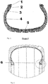
- the present invention describes a tire, which is composed of a bead rim (1), rubber mass filling (2), folding of the carcass ply (3), carcass ply (4) and reinforcement screens (5), as shown in Figure 1 .
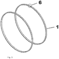
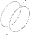
- the referred tire presents the fixation of a passive UHF RFID tag (6), as evidenced in Figure 2 , in its bead rim (1), more specifically in the outer edge (7) of the referred rim, as evidenced in Figure 3 .
- RFID tags in tires aims to monitor, automate and track the manufacturing chain from the early stages of manufacture thereof.
- the RFID tags present in the tires are installed in them during the moment of their manufacture and, however, they present some problems, such as difficulty of communication between the tag-reader and mechanical stresses.
- the present invention in order to be totally innovative and inventive, describes an RFID tag (6) that will be installed on the metallic part of the tire, more specifically on the bead rim (1), where the referred tag (6) will make use of the metallic surface to increase the equivalent antenna area, increasing the efficiency of capture and reflection of electromagnetic energy and, thus, increasing the communication distance between the reader and the tag.
- the present invention describes an RFID tag (6) that is installed in the bead region, preferably in the outer edge of one of the bead rims (1), which is the zone of the tire that suffers the least mechanical stress, both during the manufacture and the use thereof.
- the lower mechanical stress in the bead region can be justified due to the low deformation caused by the unevenness of roads with holes, steps and stones, besides being a region that suffers less stretching, contraction or torsion when compared to the regions of the sidewall of the tire.
- the present invention does not restrict the way of affixing the tag (6) to the bead rim (1), i.e., the referred tag (6) can be glued, can be attached by means of a staple, or can be tied by means of a cotton or rubberized cotton thread.
- the best option to affix the RFID tag (6) to the bead rim (1) in order to guarantee a reading range, robustness of that tag (6) to the manufacturing process and impact on the robustness of the tire, will depend on the type of tire and the type of tag (6) that will be affixed to the rim (1).
- the fixing of an RFID tag (6) on the bead rim (1) of a tire in addition to allowing the protection and integrity of the referred tag (6) in the subsequent stages of tire manufacturing, enhances the communication distance between the tag-reader and thus facilitates the tracking and monitoring of the manufacturing chain of said tire.
Landscapes
- Engineering & Computer Science (AREA)
- Mechanical Engineering (AREA)
- Physics & Mathematics (AREA)
- General Physics & Mathematics (AREA)
- Theoretical Computer Science (AREA)
- Computer Hardware Design (AREA)
- Microelectronics & Electronic Packaging (AREA)
- Tires In General (AREA)
Abstract
Description
- This invention applies to the field of circular devices made of rubber, i.e. tires, which have in their composition the presence of passive RFID tags in ultra-high frequency and without battery.
- The present invention describes a tire that, at its moment of manufacture, presents the insertion of a tag in order to promote the monitoring and automation of the manufacturing chain of said tire.
- Currently, when it comes to tires with the presence of RFID tags, most of these tags are commercially supplied by companies that manufacture them, so that they can later be installed in tires during the time of their manufacture, however, they present some problems, such as:
- - Performance problem (e.g. the range of the tag-reader communication) due to the tire construction, such as the presence of metal and restrictions on the orientation and physical location of the tag attachment on the tire;
- - Problem of tag robustness both during the tire manufacturing process (since the vulcanization process requires high temperature and pressure) and during use when mounted on a wheel (e.g. mechanical stress, torsion, friction, deformation, shock, pressurization, etc.).
- Thus, in order to obtain a better performance, this invention describes a tire that presents the insertion of the RFID tag at the time of its manufacture, allowing the traceability of the production process from the initial stages of production as well as the definition of a strategic region that aims to maximize the communication distance between the tag-reader and to cause less mechanical stress, distancing itself from resulting problems, such as the low performance of the referred tag and the damage to the tire structure.
- Document
BR PI 0800915-5 - However, in said document, the tag is placed in the interface region between the two masses of tire filling, moving away from the present invention, wherein the tag is placed on top of the rim of the tire bead, in order to take advantage of the surface provided by the rim wire.
- Document
WO2017046245 describes a tire comprising a passive transponder and a method for reading the data, in which the solution proposed in this document applies implicitly to metallic tires, those used on tractors and trucks, which have metallic wire all over the carcass ply. - In this document, the tag is placed in a region of the tire that is little exposed to mechanical deformations and is not optimized for metals, thus being away from the metal parts of the tire, i.e., the thread of the carcass ply and the bead rim, distancing itself from this invention, in which the tag is directly placed in the metal part of the tire, i.e., on top of the bead rim.
- Document
KR20060119206 - However, said document distances itself from the present invention, since in the present proposal, the RFID tag is placed on the bead rim for the use of the electromagnetic properties of the available metallic surface, such as antenna gain, and not only in the part ("Apex") of the bead with mass filling, as is the case of document
KR20060119206 - The geometry of the bead rim is not favorable to the conversion of an electromagnetic field into a near electric field. The metal surface provided by this ring allows the implementation of a resonant dielectric cavity antenna or monopole type antenna, using this surface as ground plane, which means that the closer the tag is to the metal surface, the greater the antenna gain and therefore the greater the distance of communication tag-reader.
- Document
DE202017102186 describes the placement of RFID tags on tires in a generic manner, where the distance between the tag and the outer edge of the tire is less than 1/10th of the wavelength and/or less than 25 mm. - Thus, the above-mentioned application is far from the present invention, since it does not explicitly define if the tag can be positioned on top of the bead rim and does not show a possible functioning of the tag by field coupling close to the metallic structures of the tire.
- Application
WO2017130956 describes a tire of the metallic type, that has a carcass ply as metallic wires, in which the tag present in the referred tire works with inductive coupling between the chip and is connected to a first antenna (inductor) and a second antenna of the "dipole" type. In addition, the carcass ply wires act as a third antenna and the tag is placed at a certain distance from the wires that optimize the communication distance between the tag-reader. - This way, the present invention is far from the document in question, because it makes use of a metallic coupling to the bead rim present in the tire, instead of ply wires.
- Document
US7050017 describes the many ways a RFID tag can be applied on a tire, which are: through capacitive coupling between the tag and the wires of the metal plies; through the tag positioned on the sides of the tire without metals, between the wires of the metal is and the bead ring. - In the document, said tag is electrically attached to the metal ply wires and to the bead rim and, thus, forms a "slot" type antenna structure.
- Thus, the present invention is far from the above-mentioned document given that, besides the tag being positioned on top of the bead rim, the structure obtained does not constitute a "slot" type antenna.
- Application
WO2017136752 describes a bladder used in the manufacture of a tire that contains an RFID tag. During the manufacture of the tire, the tag is placed on the inner wall of the part of the tire that serves as a mold for the bladder, and the filling thereof through pressure and temperature (vulcanization) causes the tag to stick to the bladder. - Although document
WO2017136752 claims the location of the tag on the "bead", it is far from the present invention, since the tag, in the present invention, is affixed on top of the bead rim during the manufacturing process and not on the "elastomeric" part of the tire. - Therefore, it can be concluded that the present invention is far from the documents of the state of the art presented herein, since none of them refers to tires that present an RFID tag affixed on top of the metallic region of the referred tire, preferably on the outer edge of the rims of the bead, in order to reduce the mechanical stress both during the manufacture and during the use of the tire in question.
- The present invention describes a tire, which shows the insertion of a passive UHF RFID tag at its moment of manufacture, in which said tag is affixed on top of the metallic part of the referred tire, more specifically on the bead rim, with the purpose of reducing the mechanical stress of the tire in question and allowing its tracking in the manufacturing chain since its first manufacturing stages.
- The invention can be better understood through the brief description of the figures below:
-
Figure 1 shows a sectional view of the components that make up a tire; -
Figure 2 shows a cut view of the tire, with the presence of the RFID tag; -
Figure 3 shows a perspective view of the outer edge of the bead rim; -
Figure 4 shows a perspective view of one of the side edges of the bead rim; -
Figure 5 shows a perspective view of an inner edge of the bead rim. - The present invention describes a tire, which is composed of a bead rim (1), rubber mass filling (2), folding of the carcass ply (3), carcass ply (4) and reinforcement screens (5), as shown in
Figure 1 . - At the moment of its manufacture, the referred tire presents the fixation of a passive UHF RFID tag (6), as evidenced in
Figure 2 , in its bead rim (1), more specifically in the outer edge (7) of the referred rim, as evidenced inFigure 3 . - The use of RFID tags in tires aims to monitor, automate and track the manufacturing chain from the early stages of manufacture thereof.
- Currently, the RFID tags present in the tires are installed in them during the moment of their manufacture and, however, they present some problems, such as difficulty of communication between the tag-reader and mechanical stresses.
- Thus, the existing solution in the state of the art to try to mitigate the failure and maximize the distance of communication between the tag-reader is the installation of tags in regions far from the metal parts of the tire.
- However, the present invention, in order to be totally innovative and inventive, describes an RFID tag (6) that will be installed on the metallic part of the tire, more specifically on the bead rim (1), where the referred tag (6) will make use of the metallic surface to increase the equivalent antenna area, increasing the efficiency of capture and reflection of electromagnetic energy and, thus, increasing the communication distance between the reader and the tag.
- Regarding the reduction of mechanical stress, the present invention describes an RFID tag (6) that is installed in the bead region, preferably in the outer edge of one of the bead rims (1), which is the zone of the tire that suffers the least mechanical stress, both during the manufacture and the use thereof.
- The lower mechanical stress in the bead region can be justified due to the low deformation caused by the unevenness of roads with holes, steps and stones, besides being a region that suffers less stretching, contraction or torsion when compared to the regions of the sidewall of the tire.
- The present invention does not restrict the way of affixing the tag (6) to the bead rim (1), i.e., the referred tag (6) can be glued, can be attached by means of a staple, or can be tied by means of a cotton or rubberized cotton thread.
- The best option to affix the RFID tag (6) to the bead rim (1), in order to guarantee a reading range, robustness of that tag (6) to the manufacturing process and impact on the robustness of the tire, will depend on the type of tire and the type of tag (6) that will be affixed to the rim (1).
- Thus, the fixing of an RFID tag (6) on the bead rim (1) of a tire, in addition to allowing the protection and integrity of the referred tag (6) in the subsequent stages of tire manufacturing, enhances the communication distance between the tag-reader and thus facilitates the tracking and monitoring of the manufacturing chain of said tire.
- Depending on the orientation of the reading antennas in relation to the position of the tire on a given assembly line, other RFID tag attachment locations (6) on the bead rim (1) of the tire can still increase the distance of communication tag-reader, such as the lateral edges (7), as shown in
Figure 4 , and the inner edge (8), as shown inFigure 5 .
This invention was disclosed in this specification in terms of its preferred embodiment. However, other modifications and variations are possible from the present description, being still inserted in the scope of the invention revealed here.
Claims (10)
- Tire comprising a bead rim (1), rubber mass filling (2), folding of the carcass ply (3), carcass ply (4), reinforcement screens (5) and an RFID tag (6), CHARACTERIZED by the fact that said tag (6) is affixed to the metal part of the tire where the bead rim is located (1).
- Tire, according to claim 1, CHARACTERIZED by the fact that said RFID tag (6) is affixed, more specifically, on the outer edge (7) of the bead rim (1).
- Tire, according to claim 1 or 2, CHARACTERIZED by the fact that said RFID tag (6) is affixed, more specifically, on the outer edge (7) of the bead rim (1), at the time of manufacture of the tire.
- Tire, according to claim 1, CHARACTERIZED by the fact that said RFID tag (6) is affixed, more specifically, on one of the side edges (8) of the bead rim (1).
- Tire, according to claim 4, CHARACTERIZED by the fact that said RFID tag (6) is affixed, more specifically, in one of the lateral edges (7) of the bead rim (1), at the time of the tire manufacturing.
- Tire, according to claim 1, CHARACTERIZED by the fact that said RFID tag (6) is affixed, more specifically, on the inner edge (8) of the bead rim (1).
- Tire, according to claim 6, CHARACTERIZED by the fact that said RFID tag (6) is affixed, more specifically, on the outer edge (8) of the bead rim (1), at the time of tire manufacturing.
- Tire, according to any of the claims 1 to 7, CHARACTERIZED by the fact that the RFID tag (6) is affixed on the bead rim (1) by means of staples.
- Tire, according to any of the claims 1 to 7, CHARACTERIZED by the fact that the RFID tag (6) is tied to the bead rim (1) by means of wires.
- Tire, according to any of the claims 1 to 7, CHARACTERIZED by the fact that the RFID tag (6) is glued on the bead rim (1).
Applications Claiming Priority (2)
| Application Number | Priority Date | Filing Date | Title |
|---|---|---|---|
| BR102019002815-7A BR102019002815B1 (en) | 2019-02-11 | TIRE CONTAINING AN RFID TAG | |
| PCT/BR2019/000006 WO2020163924A1 (en) | 2019-02-11 | 2019-02-26 | Tyre containing an rfid tag |
Publications (4)
| Publication Number | Publication Date |
|---|---|
| EP3925802A1 true EP3925802A1 (en) | 2021-12-22 |
| EP3925802A4 EP3925802A4 (en) | 2022-09-14 |
| EP3925802C0 EP3925802C0 (en) | 2024-04-24 |
| EP3925802B1 EP3925802B1 (en) | 2024-04-24 |
Family
ID=71945818
Family Applications (1)
| Application Number | Title | Priority Date | Filing Date |
|---|---|---|---|
| EP19914813.1A Active EP3925802B1 (en) | 2019-02-11 | 2019-02-26 | Tyre containing an rfid tag |
Country Status (3)
| Country | Link |
|---|---|
| US (1) | US11046125B2 (en) |
| EP (1) | EP3925802B1 (en) |
| WO (1) | WO2020163924A1 (en) |
Families Citing this family (2)
| Publication number | Priority date | Publication date | Assignee | Title |
|---|---|---|---|---|
| IT202100009365A1 (en) | 2021-04-14 | 2022-10-14 | Bridgestone Europe Nv Sa | TIRE PROVIDED WITH A TEMPORARY IDENTIFICATION LABEL |
| KR102598495B1 (en) * | 2021-09-30 | 2023-11-07 | 넥센타이어 주식회사 | Tire |
Family Cites Families (17)
| Publication number | Priority date | Publication date | Assignee | Title |
|---|---|---|---|---|
| US4911217A (en) * | 1989-03-24 | 1990-03-27 | The Goodyear Tire & Rubber Company | Integrated circuit transponder in a pneumatic tire for tire identification |
| US6147659A (en) * | 1996-10-14 | 2000-11-14 | Yokohama Rubber Co., Ltd. | Tire with transponder and transponder for tire |
| EP1002669B1 (en) * | 1998-03-09 | 2003-05-02 | PIRELLI PNEUMATICI Società per Azioni | Tyre containing a generator for supplying electrical power to devices incorporated into the tyre, and method for its manufacture |
| JP4179428B2 (en) * | 1998-10-01 | 2008-11-12 | 横浜ゴム株式会社 | Heavy duty pneumatic radial tire |
| DE19900082C2 (en) * | 1999-01-04 | 2003-09-25 | Continental Ag | Friction control system and pneumatic vehicle tires with sensor for it |
| US7050017B2 (en) | 2002-08-14 | 2006-05-23 | King Patrick F | RFID tire belt antenna system and method |
| KR100703605B1 (en) | 2005-05-19 | 2007-04-06 | 아시아나아이디티 주식회사 | Tires with RFID Tags |
| FR2914585B1 (en) | 2007-04-03 | 2009-07-03 | Michelin Soc Tech | PNEUMATIC COMPRISING AN ELECTRONIC MEMBER AND METHOD OF MANUFACTURING SUCH PNEUMATIC |
| JP2008305218A (en) * | 2007-06-08 | 2008-12-18 | Bridgestone Corp | Tire speed detecting system |
| EP2186658B1 (en) * | 2008-11-18 | 2012-07-04 | The Goodyear Tire & Rubber Company | Tire and electronic device assembly and method of embedding an electronic device in a tire |
| US20120291936A1 (en) * | 2011-05-19 | 2012-11-22 | Robert Edward Lionetti | Embedded transponder and tire assembly and method of construction thereof |
| KR101545385B1 (en) * | 2013-05-15 | 2015-08-18 | 아시아나아이디티 주식회사 | An management system for manufacturing tires using rfid tag |
| FR3041285B1 (en) | 2015-09-18 | 2017-10-27 | Michelin & Cie | PNEUMATIC HAVING PASSIVE TRANSPONDER AND METHOD FOR COMMUNICATING SUCH PNEUMATIC |
| WO2017130956A1 (en) | 2016-01-25 | 2017-08-03 | トッパン・フォームズ株式会社 | Tire with embedded rfid tag |
| WO2017136752A1 (en) | 2016-02-03 | 2017-08-10 | Cooper Tire & Rubber Company | Rubberized rfid tagged tire bladders |
| DE202017102186U1 (en) | 2017-04-11 | 2017-05-05 | 4Jet Technologies Gmbh | Pneumatic tire with radio chip |
| DE102017209539A1 (en) * | 2017-06-07 | 2018-12-13 | Continental Reifen Deutschland Gmbh | vehicle tires |
-
2019
- 2019-02-26 EP EP19914813.1A patent/EP3925802B1/en active Active
- 2019-02-26 WO PCT/BR2019/000006 patent/WO2020163924A1/en not_active Ceased
- 2019-04-05 US US16/376,393 patent/US11046125B2/en active Active
Also Published As
| Publication number | Publication date |
|---|---|
| BR102019002815A8 (en) | 2023-04-04 |
| US11046125B2 (en) | 2021-06-29 |
| EP3925802C0 (en) | 2024-04-24 |
| WO2020163924A1 (en) | 2020-08-20 |
| BR102019002815A2 (en) | 2020-09-29 |
| EP3925802A4 (en) | 2022-09-14 |
| EP3925802B1 (en) | 2024-04-24 |
| US20200254827A1 (en) | 2020-08-13 |
Similar Documents
| Publication | Publication Date | Title |
|---|---|---|
| CN110035912B (en) | Tyre suitable for run-flat operation, provided with electronic components | |
| CN111741858B (en) | Tire provided with radio frequency communication module | |
| EP3632705B1 (en) | Tire and tire manufacturing method | |
| EP3079926B1 (en) | Tire having an electronic device in a lower sidewall | |
| CN108025609B (en) | Tyre comprising a passive transponder and method for reading data | |
| KR100845474B1 (en) | LF ID tag for tire laying | |
| US10974553B2 (en) | Pneumatic tire equipped with an electronic member | |
| EP2524818B1 (en) | Embedded transponder and tire assembly and method of construction thereof | |
| EP3632712B1 (en) | Tire | |
| EP3632666B1 (en) | Tire manufacturing method | |
| US20040021559A1 (en) | Electronics device for a tire | |
| US12240193B2 (en) | Method for producing a tire provided with a radiofrequency communications module | |
| CN110035914A (en) | RF communication module for tires | |
| KR20140072496A (en) | RFID tag for tire | |
| EP3653406B1 (en) | Tire | |
| US11046125B2 (en) | Tire containing an RFID tag | |
| EP3738795A1 (en) | Tire | |
| CN110770049B (en) | Tyre provided with an electronic unit and suitable for run-on | |
| CN110709263A (en) | vehicle tires | |
| CN112105513A (en) | Heavy goods vehicle tyre equipped with a radio frequency communication module | |
| CN110998967B (en) | Antenna for an electronic component of a tyre | |
| BR102019002815B1 (en) | TIRE CONTAINING AN RFID TAG | |
| KR20260006150A (en) | Method for manufacturing of tire having integrated wireless electric device and tire having integrated wireless electric device |
Legal Events
| Date | Code | Title | Description |
|---|---|---|---|
| STAA | Information on the status of an ep patent application or granted ep patent |
Free format text: STATUS: THE INTERNATIONAL PUBLICATION HAS BEEN MADE |
|
| PUAI | Public reference made under article 153(3) epc to a published international application that has entered the european phase |
Free format text: ORIGINAL CODE: 0009012 |
|
| STAA | Information on the status of an ep patent application or granted ep patent |
Free format text: STATUS: REQUEST FOR EXAMINATION WAS MADE |
|
| 17P | Request for examination filed |
Effective date: 20210726 |
|
| AK | Designated contracting states |
Kind code of ref document: A1 Designated state(s): AL AT BE BG CH CY CZ DE DK EE ES FI FR GB GR HR HU IE IS IT LI LT LU LV MC MK MT NL NO PL PT RO RS SE SI SK SM TR |
|
| DAV | Request for validation of the european patent (deleted) | ||
| DAX | Request for extension of the european patent (deleted) | ||
| A4 | Supplementary search report drawn up and despatched |
Effective date: 20220818 |
|
| RIC1 | Information provided on ipc code assigned before grant |
Ipc: B60C 15/04 20060101ALN20220811BHEP Ipc: G06K 19/077 20060101ALI20220811BHEP Ipc: H01Q 1/22 20060101ALI20220811BHEP Ipc: B29D 30/00 20060101ALI20220811BHEP Ipc: B60C 19/00 20060101AFI20220811BHEP |
|
| GRAP | Despatch of communication of intention to grant a patent |
Free format text: ORIGINAL CODE: EPIDOSNIGR1 |
|
| STAA | Information on the status of an ep patent application or granted ep patent |
Free format text: STATUS: GRANT OF PATENT IS INTENDED |
|
| RIC1 | Information provided on ipc code assigned before grant |
Ipc: B60C 15/04 20060101ALN20231110BHEP Ipc: G06K 19/077 20060101ALI20231110BHEP Ipc: H01Q 1/22 20060101ALI20231110BHEP Ipc: B29D 30/00 20060101ALI20231110BHEP Ipc: B60C 19/00 20060101AFI20231110BHEP |
|
| INTG | Intention to grant announced |
Effective date: 20231208 |
|
| RIC1 | Information provided on ipc code assigned before grant |
Ipc: B60C 15/04 20060101ALN20231130BHEP Ipc: G06K 19/077 20060101ALI20231130BHEP Ipc: H01Q 1/22 20060101ALI20231130BHEP Ipc: B29D 30/00 20060101ALI20231130BHEP Ipc: B60C 19/00 20060101AFI20231130BHEP |
|
| GRAS | Grant fee paid |
Free format text: ORIGINAL CODE: EPIDOSNIGR3 |
|
| GRAA | (expected) grant |
Free format text: ORIGINAL CODE: 0009210 |
|
| STAA | Information on the status of an ep patent application or granted ep patent |
Free format text: STATUS: THE PATENT HAS BEEN GRANTED |
|
| AK | Designated contracting states |
Kind code of ref document: B1 Designated state(s): AL AT BE BG CH CY CZ DE DK EE ES FI FR GB GR HR HU IE IS IT LI LT LU LV MC MK MT NL NO PL PT RO RS SE SI SK SM TR |
|
| REG | Reference to a national code |
Ref country code: GB Ref legal event code: FG4D |
|
| REG | Reference to a national code |
Ref country code: CH Ref legal event code: EP |
|
| REG | Reference to a national code |
Ref country code: DE Ref legal event code: R096 Ref document number: 602019051128 Country of ref document: DE |
|
| REG | Reference to a national code |
Ref country code: IE Ref legal event code: FG4D |
|
| U01 | Request for unitary effect filed |
Effective date: 20240503 |
|
| U07 | Unitary effect registered |
Designated state(s): AT BE BG DE DK EE FI FR IT LT LU LV MT NL PT SE SI Effective date: 20240516 |
|
| PG25 | Lapsed in a contracting state [announced via postgrant information from national office to epo] |
Ref country code: IS Free format text: LAPSE BECAUSE OF FAILURE TO SUBMIT A TRANSLATION OF THE DESCRIPTION OR TO PAY THE FEE WITHIN THE PRESCRIBED TIME-LIMIT Effective date: 20240824 |
|
| PG25 | Lapsed in a contracting state [announced via postgrant information from national office to epo] |
Ref country code: HR Free format text: LAPSE BECAUSE OF FAILURE TO SUBMIT A TRANSLATION OF THE DESCRIPTION OR TO PAY THE FEE WITHIN THE PRESCRIBED TIME-LIMIT Effective date: 20240424 |
|
| PG25 | Lapsed in a contracting state [announced via postgrant information from national office to epo] |
Ref country code: GR Free format text: LAPSE BECAUSE OF FAILURE TO SUBMIT A TRANSLATION OF THE DESCRIPTION OR TO PAY THE FEE WITHIN THE PRESCRIBED TIME-LIMIT Effective date: 20240725 |
|
| PG25 | Lapsed in a contracting state [announced via postgrant information from national office to epo] |
Ref country code: ES Free format text: LAPSE BECAUSE OF FAILURE TO SUBMIT A TRANSLATION OF THE DESCRIPTION OR TO PAY THE FEE WITHIN THE PRESCRIBED TIME-LIMIT Effective date: 20240424 |
|
| PG25 | Lapsed in a contracting state [announced via postgrant information from national office to epo] |
Ref country code: PL Free format text: LAPSE BECAUSE OF FAILURE TO SUBMIT A TRANSLATION OF THE DESCRIPTION OR TO PAY THE FEE WITHIN THE PRESCRIBED TIME-LIMIT Effective date: 20240424 |
|
| PG25 | Lapsed in a contracting state [announced via postgrant information from national office to epo] |
Ref country code: PL Free format text: LAPSE BECAUSE OF FAILURE TO SUBMIT A TRANSLATION OF THE DESCRIPTION OR TO PAY THE FEE WITHIN THE PRESCRIBED TIME-LIMIT Effective date: 20240424 Ref country code: NO Free format text: LAPSE BECAUSE OF FAILURE TO SUBMIT A TRANSLATION OF THE DESCRIPTION OR TO PAY THE FEE WITHIN THE PRESCRIBED TIME-LIMIT Effective date: 20240724 Ref country code: IS Free format text: LAPSE BECAUSE OF FAILURE TO SUBMIT A TRANSLATION OF THE DESCRIPTION OR TO PAY THE FEE WITHIN THE PRESCRIBED TIME-LIMIT Effective date: 20240824 Ref country code: HR Free format text: LAPSE BECAUSE OF FAILURE TO SUBMIT A TRANSLATION OF THE DESCRIPTION OR TO PAY THE FEE WITHIN THE PRESCRIBED TIME-LIMIT Effective date: 20240424 Ref country code: GR Free format text: LAPSE BECAUSE OF FAILURE TO SUBMIT A TRANSLATION OF THE DESCRIPTION OR TO PAY THE FEE WITHIN THE PRESCRIBED TIME-LIMIT Effective date: 20240725 Ref country code: ES Free format text: LAPSE BECAUSE OF FAILURE TO SUBMIT A TRANSLATION OF THE DESCRIPTION OR TO PAY THE FEE WITHIN THE PRESCRIBED TIME-LIMIT Effective date: 20240424 Ref country code: RS Free format text: LAPSE BECAUSE OF FAILURE TO SUBMIT A TRANSLATION OF THE DESCRIPTION OR TO PAY THE FEE WITHIN THE PRESCRIBED TIME-LIMIT Effective date: 20240724 |
|
| PG25 | Lapsed in a contracting state [announced via postgrant information from national office to epo] |
Ref country code: CZ Free format text: LAPSE BECAUSE OF FAILURE TO SUBMIT A TRANSLATION OF THE DESCRIPTION OR TO PAY THE FEE WITHIN THE PRESCRIBED TIME-LIMIT Effective date: 20240424 |
|
| PG25 | Lapsed in a contracting state [announced via postgrant information from national office to epo] |
Ref country code: RO Free format text: LAPSE BECAUSE OF FAILURE TO SUBMIT A TRANSLATION OF THE DESCRIPTION OR TO PAY THE FEE WITHIN THE PRESCRIBED TIME-LIMIT Effective date: 20240424 Ref country code: SK Free format text: LAPSE BECAUSE OF FAILURE TO SUBMIT A TRANSLATION OF THE DESCRIPTION OR TO PAY THE FEE WITHIN THE PRESCRIBED TIME-LIMIT Effective date: 20240424 |
|
| REG | Reference to a national code |
Ref country code: DE Ref legal event code: R097 Ref document number: 602019051128 Country of ref document: DE |
|
| PG25 | Lapsed in a contracting state [announced via postgrant information from national office to epo] |
Ref country code: SM Free format text: LAPSE BECAUSE OF FAILURE TO SUBMIT A TRANSLATION OF THE DESCRIPTION OR TO PAY THE FEE WITHIN THE PRESCRIBED TIME-LIMIT Effective date: 20240424 |
|
| PG25 | Lapsed in a contracting state [announced via postgrant information from national office to epo] |
Ref country code: SM Free format text: LAPSE BECAUSE OF FAILURE TO SUBMIT A TRANSLATION OF THE DESCRIPTION OR TO PAY THE FEE WITHIN THE PRESCRIBED TIME-LIMIT Effective date: 20240424 Ref country code: SK Free format text: LAPSE BECAUSE OF FAILURE TO SUBMIT A TRANSLATION OF THE DESCRIPTION OR TO PAY THE FEE WITHIN THE PRESCRIBED TIME-LIMIT Effective date: 20240424 Ref country code: RO Free format text: LAPSE BECAUSE OF FAILURE TO SUBMIT A TRANSLATION OF THE DESCRIPTION OR TO PAY THE FEE WITHIN THE PRESCRIBED TIME-LIMIT Effective date: 20240424 Ref country code: CZ Free format text: LAPSE BECAUSE OF FAILURE TO SUBMIT A TRANSLATION OF THE DESCRIPTION OR TO PAY THE FEE WITHIN THE PRESCRIBED TIME-LIMIT Effective date: 20240424 |
|
| PLBE | No opposition filed within time limit |
Free format text: ORIGINAL CODE: 0009261 |
|
| STAA | Information on the status of an ep patent application or granted ep patent |
Free format text: STATUS: NO OPPOSITION FILED WITHIN TIME LIMIT |
|
| 26N | No opposition filed |
Effective date: 20250127 |
|
| U20 | Renewal fee for the european patent with unitary effect paid |
Year of fee payment: 7 Effective date: 20250227 |
|
| PG25 | Lapsed in a contracting state [announced via postgrant information from national office to epo] |
Ref country code: MC Free format text: LAPSE BECAUSE OF FAILURE TO SUBMIT A TRANSLATION OF THE DESCRIPTION OR TO PAY THE FEE WITHIN THE PRESCRIBED TIME-LIMIT Effective date: 20240424 |
|
| REG | Reference to a national code |
Ref country code: CH Ref legal event code: PL |
|
| PG25 | Lapsed in a contracting state [announced via postgrant information from national office to epo] |
Ref country code: CH Free format text: LAPSE BECAUSE OF NON-PAYMENT OF DUE FEES Effective date: 20250228 |
|
| GBPC | Gb: european patent ceased through non-payment of renewal fee |
Effective date: 20250226 |
|
| PG25 | Lapsed in a contracting state [announced via postgrant information from national office to epo] |
Ref country code: GB Free format text: LAPSE BECAUSE OF NON-PAYMENT OF DUE FEES Effective date: 20250226 |
|
| PG25 | Lapsed in a contracting state [announced via postgrant information from national office to epo] |
Ref country code: IE Free format text: LAPSE BECAUSE OF NON-PAYMENT OF DUE FEES Effective date: 20250226 |
|
| U20 | Renewal fee for the european patent with unitary effect paid |
Year of fee payment: 8 Effective date: 20260227 |
|
| PG25 | Lapsed in a contracting state [announced via postgrant information from national office to epo] |
Ref country code: CY Free format text: LAPSE BECAUSE OF FAILURE TO SUBMIT A TRANSLATION OF THE DESCRIPTION OR TO PAY THE FEE WITHIN THE PRESCRIBED TIME-LIMIT Effective date: 20240424 |
|
| PG25 | Lapsed in a contracting state [announced via postgrant information from national office to epo] |
Ref country code: TR Free format text: LAPSE BECAUSE OF FAILURE TO SUBMIT A TRANSLATION OF THE DESCRIPTION OR TO PAY THE FEE WITHIN THE PRESCRIBED TIME-LIMIT Effective date: 20240424 |