EP3925648A1 - Liquid medicine administration apparatus - Google Patents
Liquid medicine administration apparatus Download PDFInfo
- Publication number
- EP3925648A1 EP3925648A1 EP20782052.3A EP20782052A EP3925648A1 EP 3925648 A1 EP3925648 A1 EP 3925648A1 EP 20782052 A EP20782052 A EP 20782052A EP 3925648 A1 EP3925648 A1 EP 3925648A1
- Authority
- EP
- European Patent Office
- Prior art keywords
- liquid medicine
- administration device
- plunger
- motor
- medicine administration
- Prior art date
- Legal status (The legal status is an assumption and is not a legal conclusion. Google has not performed a legal analysis and makes no representation as to the accuracy of the status listed.)
- Granted
Links
Images



Classifications
-
- A—HUMAN NECESSITIES
- A61—MEDICAL OR VETERINARY SCIENCE; HYGIENE
- A61M—DEVICES FOR INTRODUCING MEDIA INTO, OR ONTO, THE BODY; DEVICES FOR TRANSDUCING BODY MEDIA OR FOR TAKING MEDIA FROM THE BODY; DEVICES FOR PRODUCING OR ENDING SLEEP OR STUPOR
- A61M5/00—Devices for bringing media into the body in a subcutaneous, intra-vascular or intramuscular way; Accessories therefor, e.g. filling or cleaning devices, arm-rests
- A61M5/14—Infusion devices, e.g. infusing by gravity; Blood infusion; Accessories therefor
- A61M5/142—Pressure infusion, e.g. using pumps
- A61M5/145—Pressure infusion, e.g. using pumps using pressurised reservoirs, e.g. pressurised by means of pistons
- A61M5/1452—Pressure infusion, e.g. using pumps using pressurised reservoirs, e.g. pressurised by means of pistons pressurised by means of pistons
-
- A—HUMAN NECESSITIES
- A61—MEDICAL OR VETERINARY SCIENCE; HYGIENE
- A61M—DEVICES FOR INTRODUCING MEDIA INTO, OR ONTO, THE BODY; DEVICES FOR TRANSDUCING BODY MEDIA OR FOR TAKING MEDIA FROM THE BODY; DEVICES FOR PRODUCING OR ENDING SLEEP OR STUPOR
- A61M5/00—Devices for bringing media into the body in a subcutaneous, intra-vascular or intramuscular way; Accessories therefor, e.g. filling or cleaning devices, arm-rests
- A61M5/14—Infusion devices, e.g. infusing by gravity; Blood infusion; Accessories therefor
- A61M5/142—Pressure infusion, e.g. using pumps
- A61M5/14244—Pressure infusion, e.g. using pumps adapted to be carried by the patient, e.g. portable on the body
- A61M5/14248—Pressure infusion, e.g. using pumps adapted to be carried by the patient, e.g. portable on the body of the skin patch type
-
- A—HUMAN NECESSITIES
- A61—MEDICAL OR VETERINARY SCIENCE; HYGIENE
- A61M—DEVICES FOR INTRODUCING MEDIA INTO, OR ONTO, THE BODY; DEVICES FOR TRANSDUCING BODY MEDIA OR FOR TAKING MEDIA FROM THE BODY; DEVICES FOR PRODUCING OR ENDING SLEEP OR STUPOR
- A61M5/00—Devices for bringing media into the body in a subcutaneous, intra-vascular or intramuscular way; Accessories therefor, e.g. filling or cleaning devices, arm-rests
- A61M5/14—Infusion devices, e.g. infusing by gravity; Blood infusion; Accessories therefor
- A61M5/142—Pressure infusion, e.g. using pumps
- A61M5/145—Pressure infusion, e.g. using pumps using pressurised reservoirs, e.g. pressurised by means of pistons
-
- A—HUMAN NECESSITIES
- A61—MEDICAL OR VETERINARY SCIENCE; HYGIENE
- A61M—DEVICES FOR INTRODUCING MEDIA INTO, OR ONTO, THE BODY; DEVICES FOR TRANSDUCING BODY MEDIA OR FOR TAKING MEDIA FROM THE BODY; DEVICES FOR PRODUCING OR ENDING SLEEP OR STUPOR
- A61M5/00—Devices for bringing media into the body in a subcutaneous, intra-vascular or intramuscular way; Accessories therefor, e.g. filling or cleaning devices, arm-rests
- A61M5/14—Infusion devices, e.g. infusing by gravity; Blood infusion; Accessories therefor
- A61M5/168—Means for controlling media flow to the body or for metering media to the body, e.g. drip meters, counters ; Monitoring media flow to the body
- A61M5/172—Means for controlling media flow to the body or for metering media to the body, e.g. drip meters, counters ; Monitoring media flow to the body electrical or electronic
-
- A—HUMAN NECESSITIES
- A61—MEDICAL OR VETERINARY SCIENCE; HYGIENE
- A61M—DEVICES FOR INTRODUCING MEDIA INTO, OR ONTO, THE BODY; DEVICES FOR TRANSDUCING BODY MEDIA OR FOR TAKING MEDIA FROM THE BODY; DEVICES FOR PRODUCING OR ENDING SLEEP OR STUPOR
- A61M5/00—Devices for bringing media into the body in a subcutaneous, intra-vascular or intramuscular way; Accessories therefor, e.g. filling or cleaning devices, arm-rests
- A61M5/14—Infusion devices, e.g. infusing by gravity; Blood infusion; Accessories therefor
- A61M5/142—Pressure infusion, e.g. using pumps
- A61M5/145—Pressure infusion, e.g. using pumps using pressurised reservoirs, e.g. pressurised by means of pistons
- A61M2005/14506—Pressure infusion, e.g. using pumps using pressurised reservoirs, e.g. pressurised by means of pistons mechanically driven, e.g. spring or clockwork
-
- A—HUMAN NECESSITIES
- A61—MEDICAL OR VETERINARY SCIENCE; HYGIENE
- A61M—DEVICES FOR INTRODUCING MEDIA INTO, OR ONTO, THE BODY; DEVICES FOR TRANSDUCING BODY MEDIA OR FOR TAKING MEDIA FROM THE BODY; DEVICES FOR PRODUCING OR ENDING SLEEP OR STUPOR
- A61M2205/00—General characteristics of the apparatus
- A61M2205/33—Controlling, regulating or measuring
- A61M2205/3306—Optical measuring means
-
- A—HUMAN NECESSITIES
- A61—MEDICAL OR VETERINARY SCIENCE; HYGIENE
- A61M—DEVICES FOR INTRODUCING MEDIA INTO, OR ONTO, THE BODY; DEVICES FOR TRANSDUCING BODY MEDIA OR FOR TAKING MEDIA FROM THE BODY; DEVICES FOR PRODUCING OR ENDING SLEEP OR STUPOR
- A61M2205/00—General characteristics of the apparatus
- A61M2205/33—Controlling, regulating or measuring
- A61M2205/3365—Rotational speed
-
- A—HUMAN NECESSITIES
- A61—MEDICAL OR VETERINARY SCIENCE; HYGIENE
- A61M—DEVICES FOR INTRODUCING MEDIA INTO, OR ONTO, THE BODY; DEVICES FOR TRANSDUCING BODY MEDIA OR FOR TAKING MEDIA FROM THE BODY; DEVICES FOR PRODUCING OR ENDING SLEEP OR STUPOR
- A61M2205/00—General characteristics of the apparatus
- A61M2205/82—Internal energy supply devices
- A61M2205/8206—Internal energy supply devices battery-operated
-
- F—MECHANICAL ENGINEERING; LIGHTING; HEATING; WEAPONS; BLASTING
- F04—POSITIVE - DISPLACEMENT MACHINES FOR LIQUIDS; PUMPS FOR LIQUIDS OR ELASTIC FLUIDS
- F04B—POSITIVE-DISPLACEMENT MACHINES FOR LIQUIDS; PUMPS
- F04B2201/00—Pump parameters
- F04B2201/12—Parameters of driving or driven means
- F04B2201/1201—Rotational speed of the axis
Definitions
- the present invention relates to a liquid medicine administration device capable of reducing a load on a power supply at the start of use.
- Patent Literature 1 there is known a syringe pump type liquid medicine administration device that administers a liquid medicine filled in a liquid medicine container to a living body.
- the syringe pump type liquid medicine administration device includes a power supply, a drive mechanism, and a control unit, and continuously administers the liquid medicine with high accuracy for a long time by moving a plunger little by little by the drive mechanism.
- a power supply capacity is set to a minimum capacity capable of securing a capacity sufficient for normal administration of the liquid medicine after the refrigeration and storage in consideration of a decrease in the power supply capacity due to natural discharge during the refrigerated storage, and the power supply is configured by a button battery having a capacity sufficient to cover the set capacity.
- Patent Literature 1 JP 2015-181869 A
- the control unit drives the drive mechanism simultaneously, and moves the plunger little by little to administer the liquid medicine to the living body.
- a small button battery is adopted as the power supply
- a drive device is driven simultaneously, a load on the power supply increases, and a power supply voltage temporarily drops greatly.
- the power supply voltage is smaller than a specified value, a safety device operates and all operations are stopped. Therefore, the administration of the liquid medicine is stopped.
- An object of the present invention is to provide a liquid medicine administration device capable of reducing a load on a power supply at the start of use.
- an aspect of the present invention provides a liquid medicine administration device including: a drive mechanism that advances a plunger that pushes a liquid medicine from a liquid medicine container filled with the liquid medicine toward a distal end opening of the liquid medicine container; and a control unit that controls operation of the drive mechanism, in which the drive mechanism includes a motor that applies, to the plunger, a drive force for advancing the plunger, and a rotation detection unit that detects a rotation of the motor, and when driving the drive mechanism, the control unit starts the rotation detection unit after starting the motor.
- the rotation detection unit since the rotation detection unit is started after the motor is started, the load on the power supply at the start of use can be reduced.
- Figs. 1 to 6 are views for explaining a liquid medicine administration system 10, a liquid medicine administration device 100, and an administration tool 200 according to the present embodiment.
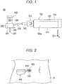
- Fig. 1 is a side view of a liquid medicine administration system.
- Fig. 2 is a view schematically illustrating a usage example of the liquid medicine administration system.
- Fig. 3 is a schematic perspective view of a liquid medicine administration device.
- Fig. 4 is a schematic perspective view of a chassis included in a housing and each component member assembled to the chassis.
- Fig. 5 is a plan view of the liquid medicine administration device illustrating a state before a plunger is moved forward.
- Fig. 6 is a plan view of the liquid medicine administration device illustrating a state after the plunger is moved forward.
- an arrow X in each drawing indicates a "longitudinal direction (longitudinal direction of a liquid medicine container 110)" of the liquid medicine administration device 100
- an arrow Y indicates a "width direction (depth direction)” of the liquid medicine administration device 100
- an arrow Z indicates a "height direction” of the liquid medicine administration device 100.
- the liquid medicine administration system 10 is used to administer a liquid medicine into a living body. As illustrated in Fig. 1 , the liquid medicine administration system 10 includes the liquid medicine administration device 100 and the administration tool 200.
- the liquid medicine administration device 100 and the administration tool 200 are configured as a patch type used by being stuck on a body surface (skin) H of a user.
- a body part of the user to which the liquid medicine administration device 100 and the administration tool 200 are attached is not particularly limited, but is, for example, an abdomen or a femoral part.
- the liquid medicine administration system 10 can continuously administer a liquid medicine (not illustrated) filled in the liquid medicine container 110 included in the liquid medicine administration device 100 into the living body for a relatively long time (for example, approximately several minutes to several hours) by a pressing action of a plunger 130 (see Fig. 4 ) to be described later.
- the liquid medicine administration system 10 may intermittently administer the liquid medicine into the living body.
- the liquid medicine administration device 100 includes the liquid medicine container 110 including a cylindrical (barrel-shaped) main body 111 filled with the liquid medicine, a housing 120 that holds the liquid medicine container 110, the plunger 130 that pushes the liquid medicine in the liquid medicine container 110, a drive mechanism 140 that advances the plunger 130 toward a distal end opening of the liquid medicine container 110, a detection unit 150 that detects a portion 134 to be detected of the plunger 130 and detects completion of feeding of the liquid medicine based on a detection result, and a control unit 160 that controls operation of the drive mechanism.
- the liquid medicine container 110 including a cylindrical (barrel-shaped) main body 111 filled with the liquid medicine, a housing 120 that holds the liquid medicine container 110, the plunger 130 that pushes the liquid medicine in the liquid medicine container 110, a drive mechanism 140 that advances the plunger 130 toward a distal end opening of the liquid medicine container 110, a detection unit 150 that detects a portion 134 to be detected of the plunger 130 and detects completion of feeding of the liquid
- the housing 120 includes a box-shaped housing main body 120a in which an accommodation space 128 is formed, and a chassis (corresponding to a "support portion") 127 which is accommodated in the accommodation space 128 of the housing main body 120a and can be fixed to the housing main body 120a.
- a window portion 123a that allows the inside of the accommodation space 128 to be visually recognized from the outside of the housing 120 is formed on an upper surface 123 of the housing main body 120a.
- the window portion 123a is formed by providing a transparent or translucent portion in a part of the housing main body 120a.
- a proximal end opening 125 for inserting a chassis 127 into the accommodation space 128 of the housing main body 120a is formed on a proximal end side in a longitudinal direction of the housing main body 120a.
- the proximal end opening 125 of the housing main body 120a is closed by a lid member (not illustrated) in a state in which the chassis 127 is accommodated in the accommodation space 128.
- a bottom surface 121 of the housing main body 120a is provided with a sheet-like sticking portion (not illustrated) that can be stuck to the body surface H of the user.
- a peelable protective sheet is attached to a sticking surface of the sticking portion.
- the chassis 127 holds the liquid medicine container 110, the plunger 130, the drive mechanism 140, the detection unit 150, the control unit 160, and a power supply unit 170.
- the liquid medicine container 110 is a so-called prefilled liquid medicine container. Therefore, the liquid medicine is filled in a lumen 111a of the main body 111 of the liquid medicine container 110 in advance.
- the liquid medicine include protein preparations, narcotic analgesics, diuretics, and the like.
- a sealing member (not illustrated) for preventing leakage of the liquid medicine is disposed in the distal end opening (discharge port) formed at a distal end 112 of the liquid medicine container 110.
- the distal end opening of the liquid medicine container 110 is disposed so as to protrude outward from the housing main body 120a.
- an attachment portion 115 that is connected to a tube 240 (see Fig. 1 ) to be described later is attached to a distal end portion of the liquid medicine container 110, the distal end portion protruding from the housing main body 120a.
- a main body 131 of the plunger 130 is inserted into the lumen 111a of the main body 111 of the liquid medicine container 110 (see Figs. 4 and 5 ).
- a gasket 135 slidable on an inner wall of the liquid medicine container 110 is disposed at a distal end of the main body 131 of the plunger 130.
- the gasket 135 liquid-tightly seals a proximal end side of the gasket 135 by liquid-tightly bringing an outer circumferential portion of the gasket 135 into close contact with an inner circumferential surface of the main body 111 of the liquid medicine container 110.
- the gasket 135 is configured to be shrinkable in a direction (longitudinal direction) in which the plunger 130 advances when the plunger 130 advances in a state in which the gasket 135 abuts against a distal end inner wall 112a (see Fig. 5 ) of the liquid medicine container 110.
- the gasket 135 can be made of, for example, a flexible resin material such as a rubber material or an elastomer so as to be shrinkable as described above.
- the gasket 135 has a tapered shape in which an outer diameter decreases toward a distal end side. Furthermore, the shape of the gasket 135 is substantially the same as the shape of the distal end inner wall 112a of the liquid medicine container 110.
- the portion 134 to be detected is provided at a proximal end of the plunger 130.
- the portion 134 to be detected is used to detect completion of feeding of the liquid medicine by the liquid medicine administration device 100.
- the control unit 160 controls a liquid medicine feeding operation of the liquid medicine administration device 100.
- the control unit 160 can be configured by, for example, a known microcomputer (electronic circuit element) on which a CPU, a RAM, a ROM, and the like are mounted.
- the control unit 160 integrally controls operations of the drive mechanism 140, the detection unit 150, and the power supply unit 170.
- the detection unit 150 is disposed in the chassis 127. As illustrated in Fig. 6 , the detection unit 150 detects completion of feeding of the liquid medicine of the liquid medicine administration device 100 when the portion 134 to be detected included in the plunger 130 comes into contact with the detection unit 150.
- the detection unit 150 can be configured by, for example, a known contact-type sensor that transmits a predetermined electric signal when the portion 134 to be detected comes into contact with the detection unit 150.
- the control unit 160 acquires information regarding completion of feeding of the liquid medicine by receiving the electric signal from the detection unit 150. Note that, when the plunger 130 advances by a predetermined amount, the specific configuration and the like of the detection unit 150 are not particularly limited as long as a position of the portion 134 to be detected of the plunger 130 can be detected.
- the power supply unit 170 can be configured by, for example, a known button battery or the like.
- the liquid medicine administration device 100 is required to be downsized. Therefore, a small button battery is used as the power supply unit 170.
- the drive mechanism 140 includes a motor 141 that receives a drive current from the power supply unit 170 and applies a drive force, a speed reduction mechanism 143 that includes a gear or the like transmitting the drive force of the motor 141, an encoder 146 that is provided adjacent to the speed reduction mechanism 143 and includes a photointerrupter as a rotation detection unit that detects rotation of the motor 141 and a slit plate that rotates in accordance with the rotation of the motor 141, and a feed screw 147 that is connected to the speed reduction mechanism 143.
- the feed screw 147 is connected to a proximal end connection portion 133 disposed in the vicinity of the proximal end of the plunger 130.
- the feed screw 147 converts a rotational motion transmitted from the speed reduction mechanism 143 into a linear motion to advance the plunger 130 in the longitudinal direction (X direction).
- the plunger 130 advances toward a distal end side of the liquid medicine container 110 to push the liquid medicine from the lumen 111a of the main body 111 of the liquid medicine container 110 to the tube 240 (see Fig. 1 ).
- the administration tool 200 is configured to be connectable to the liquid medicine administration device 100.
- the administration tool 200 includes a connector 210, a needle tube 220 that punctures the living body, a puncture unit (cannula housing) 230, the tube 240, and a puncture assisting tool 250 that assists in puncturing the living body with the needle tube 220.
- the connector 210 is configured to be connectable to the liquid medicine administration device 100 via an attachment portion 215 fixed to the connector 210.
- the attachment portion 215 can be connected to the liquid medicine administration device 100 by being externally fitted to the attachment portion 115 (see Fig. 4 ) provided in the vicinity of the distal end 112 of the liquid medicine container 110 protruding to the outside of the housing 120.
- connection needle portion (not illustrated) through which the sealing member (not illustrated) disposed at a distal end portion of the liquid medicine container 110 can be inserted is disposed.
- the tube 240 communicates with the lumen 111a of the main body 111 of the liquid medicine container 110 via the connection needle portion.
- a flow path (not illustrated) through which the tube 240 communicates with a lumen of the needle tube 220 is formed.
- the liquid medicine fed to the puncture unit 230 through the tube 240 is administered into the living body through the flow path formed inside the puncture unit 230 and the needle tube 220.
- the puncture assisting tool 250 When the liquid medicine is fed to the user, the puncture assisting tool 250 is attached to the puncture unit 230.
- the puncture assisting tool 250 holds an introduction needle (inner needle) 251.
- the introduction needle 251 protrudes from a distal end of the needle tube 220 in a state in which the puncture assisting tool 250 is attached to the puncture unit 230.
- the puncture assisting tool 250 is removed from the puncture unit 230 after puncturing the living body with the needle tube 220.
- the introduction needle 251 is removed from the lumen of the needle tube 220.
- the puncture assisting tool 250 is removed, and the puncture unit 230 is left on the body surface H of the user in a state in which the needle tube 220 is indwelled in the living body.
- the plunger 130 of the liquid medicine administration device 100 advances in the liquid medicine container 110 in this state, the liquid medicine filled in the liquid medicine container 110 is fed to the lumen of the needle tube 220 via the tube 240 and the flow path of the puncture unit 230.
- the introduction needle 251 can be formed of, for example, a metal needle.
- the needle tube 220 can be formed of, for example, a resin tubular member (cannula).
- the administration tool 200 is configured as a patch type used by being stuck on the body surface H of the user.
- a sheet-like sticking portion (not illustrated) that can be stuck to the body surface H is provided on a contact surface (bottom surface) 231 of the puncture unit 230 of the administration tool 200.
- a peelable protective sheet is attached to a sticking surface of the sticking portion.
- the liquid medicine administration device 100 is required to be reduced in size and cost in order to facilitate handling at the time of use and to save a storage space at the time of storage. Therefore, a small button battery is adopted as the power supply unit 170. Since there is a limit to supplying large electric power instantaneously, the button battery cannot apply a large load at a time. Therefore, the control unit 160 controls the drive mechanism 140 as follows.
- Fig. 7A is a block diagram of a control system of the liquid medicine administration device 100.
- Fig. 7B is a diagram schematically illustrating a configuration of the encoder of Fig. 7A .
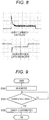
- Fig. 8 is a graph illustrating temporal changes in an output current and a power supply voltage of the control unit 160 at the start of use.
- Fig. 9 is an operation flowchart of the control unit 160.
- Fig. 10 is a diagram illustrating a temporal change in a power supply voltage of the related art at the start of using the liquid medicine administration device 100.
- Fig. 11 is a diagram illustrating a temporal change in a power supply voltage of the present application at the start of using the liquid medicine administration device 100.
- the control unit 160 is electrically connected to the motor 141.
- a rotation shaft of the motor 141 is mechanically connected to the encoder 146 as the rotation detection unit and the speed reduction mechanism 143.
- the encoder 146 includes a photointerrupter 144 including an optical sensor and a slit plate 145 in which a large number of slits are radially formed, and detects the rotation of the motor 141 by detecting whether or not light passes through the slits of the slit plate 145 with the optical sensor of the photointerrupter 144.
- the photointerrupter 144 is electrically connected to the control unit 160. Note that, in the present embodiment, the encoder 146 using the photointerrupter 144 as the rotation detection unit has been exemplified, but an encoder using a magnetic sensor may be used.
- the control unit 160 rotates the motor 141, the speed reduction mechanism 143 is driven, and the plunger 130 advances in the liquid medicine container 110 (see Figs. 5 and 6 ).
- the encoder 146 provided adjacent to the speed reduction mechanism 143 detects the rotation of the motor 141, and the control unit 160 calculates a rotation speed of the motor 141 based on the rotation of the motor 141 detected by the encoder 146.
- the rotation of the motor 141 detected by the encoder 146 is fed back to the control unit 160, and the control unit 160 calculates the rotation speed of the motor 141 in accordance with the feedback and determines whether or not the motor 141 is rotating.
- the rotation detection unit can also be incorporated as a part of the speed reduction mechanism 143.
- the slit plate 145 is omitted, and instead of this, a large number of slits are radially provided in the gear of the speed reduction mechanism 143, and the rotation of the motor 141 is detected by detecting whether or not light passes through the slits provided in the gear by using the optical sensor of the photointerrupter.
- the encoder includes the gear of the speed reduction mechanism 143 and the photointerrupter.
- a momentarily excessively large current (starting current that forms a peak current) flows, after that, the current decreases to a steady state current in response to the magnitude of the load, and is stabilized.
- a voltage of the button battery which is the power supply unit 170 decreases momentarily excessively in response to the magnitude of the flowing current, and then the decrease in the voltage is stabilized.
- the voltage of the button battery is too low, all the operations of the liquid medicine administration device 100 are stopped, and the administration of the medicine is interrupted.
- the control unit 160 first drives the motor 141 (S100), and when the current of the motor 141 decreases to a steady state current in response to the load (S101), starts the photointerrupter 144 (S102).
- the control unit 160 first drives the motor 141, and starts the photointerrupter 144 after the current of the motor 141 is stabilized, so that the starting currents of the motor 141 and the photointerrupter 144 are not supplied from the power supply unit 170 at a time.
- the motor 141 and the photointerrupter 144 are started at the same timing at the start of using the liquid medicine administration device 100, as illustrated in Fig. 10 , the power supply voltage drops greatly and the safety device of the liquid medicine administration device 100 is easy to be operated.
- the photointerrupter 144 is started after the motor 141 is started, as illustrated in Fig. 11 , the voltage temporarily drops twice, but the power supply voltage does not drop greatly as in the related art, and the safety device is difficult to be operated. That is, the administration of the liquid medicine is not interrupted.
- the load on the power supply unit 170 at the start of using the liquid medicine administration device 100 can be reduced. According to this, a battery constituting the power supply unit 170 can last longer than the related art. Furthermore, even in a case where the voltage of the battery decreases or internal resistance of the battery increases, the operation range of the battery can be expanded. Furthermore, since electric capacity of the power supply unit 170 can be reduced, miniaturization and cost reduction of the liquid medicine administration device 100 can be achieved.
- liquid medicine administration device of the present invention has been described above through the embodiments, but the present invention is not limited to each of the configurations described above, and can be appropriately changed based on the description of the claims.
Landscapes
- Health & Medical Sciences (AREA)
- Vascular Medicine (AREA)
- Engineering & Computer Science (AREA)
- Anesthesiology (AREA)
- Biomedical Technology (AREA)
- Heart & Thoracic Surgery (AREA)
- Hematology (AREA)
- Life Sciences & Earth Sciences (AREA)
- Animal Behavior & Ethology (AREA)
- General Health & Medical Sciences (AREA)
- Public Health (AREA)
- Veterinary Medicine (AREA)
- Dermatology (AREA)
- Infusion, Injection, And Reservoir Apparatuses (AREA)
Abstract
Description
- The present invention relates to a liquid medicine administration device capable of reducing a load on a power supply at the start of use.
- In the related art, as disclosed in Patent Literature 1, there is known a syringe pump type liquid medicine administration device that administers a liquid medicine filled in a liquid medicine container to a living body. The syringe pump type liquid medicine administration device includes a power supply, a drive mechanism, and a control unit, and continuously administers the liquid medicine with high accuracy for a long time by moving a plunger little by little by the drive mechanism.
- This type of liquid medicine administration device is refrigerated and stored until they are used by a user. Therefore, the liquid medicine administration device is devised to be extremely downsized so that a refrigerated storage space is small. For example, a power supply capacity is set to a minimum capacity capable of securing a capacity sufficient for normal administration of the liquid medicine after the refrigeration and storage in consideration of a decrease in the power supply capacity due to natural discharge during the refrigerated storage, and the power supply is configured by a button battery having a capacity sufficient to cover the set capacity.
- Patent Literature 1:
JP 2015-181869 A - At the time of using the liquid medicine administration device, when a power switch is turned on, the control unit drives the drive mechanism simultaneously, and moves the plunger little by little to administer the liquid medicine to the living body. However, since a small button battery is adopted as the power supply, when a drive device is driven simultaneously, a load on the power supply increases, and a power supply voltage temporarily drops greatly. In the liquid medicine administration device, when the power supply voltage is smaller than a specified value, a safety device operates and all operations are stopped. Therefore, the administration of the liquid medicine is stopped.
- An object of the present invention is to provide a liquid medicine administration device capable of reducing a load on a power supply at the start of use.
- In order to achieve the object described above, an aspect of the present invention provides a liquid medicine administration device including: a drive mechanism that advances a plunger that pushes a liquid medicine from a liquid medicine container filled with the liquid medicine toward a distal end opening of the liquid medicine container; and a control unit that controls operation of the drive mechanism, in which the drive mechanism includes a motor that applies, to the plunger, a drive force for advancing the plunger, and a rotation detection unit that detects a rotation of the motor, and when driving the drive mechanism, the control unit starts the rotation detection unit after starting the motor.
- According to an aspect of the present invention, in the liquid medicine administration device, since the rotation detection unit is started after the motor is started, the load on the power supply at the start of use can be reduced.
-
-
Fig. 1 is a side view of a liquid medicine administration system. -
Fig. 2 is a view schematically illustrating a usage example of a liquid medicine administration system. -
Fig. 3 is a schematic perspective view of a liquid medicine administration device. -
Fig. 4 is a schematic perspective view of a chassis included in a housing and each component member assembled to the chassis. -
Fig. 5 is a plan view of a liquid medicine administration device illustrating a state before a plunger is moved forward. -
Fig. 6 is a plan view of a liquid medicine administration device illustrating a state after the plunger is moved forward. -
Fig. 7A is a block diagram of a control system of a liquid medicine administration device. -
Fig. 7B is a diagram schematically illustrating a configuration of an encoder ofFig. 7A . -
Fig. 8 is a graph illustrating temporal changes in an output current and a power supply voltage of a control unit at the start of use. -
Fig. 9 is an operation flowchart of a control unit. -
Fig. 10 is a diagram illustrating a temporal change in a power supply voltage of the related art at the start of use of a liquid medicine administration device. -
Fig. 11 is a diagram illustrating a temporal change in a power supply voltage of the present application at the start of using a liquid medicine administration device. - Hereinafter, embodiments of the present invention will be described with reference to the accompanying drawings. Note that, the following description does not limit the technical scope or meaning of terms described in the claims. Furthermore, dimensional ratios in the drawings are exaggerated for convenience of description, and may be different from actual ratios.
-
Figs. 1 to 6 are views for explaining a liquidmedicine administration system 10, a liquidmedicine administration device 100, and anadministration tool 200 according to the present embodiment.Fig. 1 is a side view of a liquid medicine administration system.Fig. 2 is a view schematically illustrating a usage example of the liquid medicine administration system.Fig. 3 is a schematic perspective view of a liquid medicine administration device.Fig. 4 is a schematic perspective view of a chassis included in a housing and each component member assembled to the chassis.Fig. 5 is a plan view of the liquid medicine administration device illustrating a state before a plunger is moved forward.Fig. 6 is a plan view of the liquid medicine administration device illustrating a state after the plunger is moved forward. Note that, an arrow X in each drawing indicates a "longitudinal direction (longitudinal direction of a liquid medicine container 110)" of the liquidmedicine administration device 100, an arrow Y indicates a "width direction (depth direction)" of the liquidmedicine administration device 100, and an arrow Z indicates a "height direction" of the liquidmedicine administration device 100. - The liquid
medicine administration system 10 is used to administer a liquid medicine into a living body. As illustrated inFig. 1 , the liquidmedicine administration system 10 includes the liquidmedicine administration device 100 and theadministration tool 200. - As illustrated in
Fig. 2 , the liquidmedicine administration device 100 and theadministration tool 200 are configured as a patch type used by being stuck on a body surface (skin) H of a user. A body part of the user to which the liquidmedicine administration device 100 and theadministration tool 200 are attached is not particularly limited, but is, for example, an abdomen or a femoral part. - For example, the liquid
medicine administration system 10 can continuously administer a liquid medicine (not illustrated) filled in theliquid medicine container 110 included in the liquidmedicine administration device 100 into the living body for a relatively long time (for example, approximately several minutes to several hours) by a pressing action of a plunger 130 (seeFig. 4 ) to be described later. Note that, the liquidmedicine administration system 10 may intermittently administer the liquid medicine into the living body. - As illustrated in
Figs. 3 to 6 , the liquidmedicine administration device 100 includes theliquid medicine container 110 including a cylindrical (barrel-shaped)main body 111 filled with the liquid medicine, ahousing 120 that holds theliquid medicine container 110, theplunger 130 that pushes the liquid medicine in theliquid medicine container 110, adrive mechanism 140 that advances theplunger 130 toward a distal end opening of theliquid medicine container 110, adetection unit 150 that detects aportion 134 to be detected of theplunger 130 and detects completion of feeding of the liquid medicine based on a detection result, and acontrol unit 160 that controls operation of the drive mechanism. - As illustrated in
Figs. 3 and 4 , thehousing 120 includes a box-shaped housingmain body 120a in which anaccommodation space 128 is formed, and a chassis (corresponding to a "support portion") 127 which is accommodated in theaccommodation space 128 of the housingmain body 120a and can be fixed to the housingmain body 120a. - As illustrated in
Fig. 3 , awindow portion 123a that allows the inside of theaccommodation space 128 to be visually recognized from the outside of thehousing 120 is formed on anupper surface 123 of the housingmain body 120a. Thewindow portion 123a is formed by providing a transparent or translucent portion in a part of the housingmain body 120a. - A
proximal end opening 125 for inserting achassis 127 into theaccommodation space 128 of the housingmain body 120a is formed on a proximal end side in a longitudinal direction of the housingmain body 120a. The proximal end opening 125 of the housingmain body 120a is closed by a lid member (not illustrated) in a state in which thechassis 127 is accommodated in theaccommodation space 128. - A
bottom surface 121 of the housingmain body 120a is provided with a sheet-like sticking portion (not illustrated) that can be stuck to the body surface H of the user. In an initial state before the liquidmedicine administration device 100 is attached to the user, a peelable protective sheet is attached to a sticking surface of the sticking portion. - As illustrated in
Fig. 4 , thechassis 127 holds theliquid medicine container 110, theplunger 130, thedrive mechanism 140, thedetection unit 150, thecontrol unit 160, and apower supply unit 170. - The
liquid medicine container 110 is a so-called prefilled liquid medicine container. Therefore, the liquid medicine is filled in alumen 111a of themain body 111 of theliquid medicine container 110 in advance. Examples of the liquid medicine include protein preparations, narcotic analgesics, diuretics, and the like. - A sealing member (not illustrated) for preventing leakage of the liquid medicine is disposed in the distal end opening (discharge port) formed at a
distal end 112 of theliquid medicine container 110. As illustrated inFig. 3 , the distal end opening of theliquid medicine container 110 is disposed so as to protrude outward from the housingmain body 120a. Furthermore, anattachment portion 115 that is connected to a tube 240 (seeFig. 1 ) to be described later is attached to a distal end portion of theliquid medicine container 110, the distal end portion protruding from the housingmain body 120a. - A
main body 131 of theplunger 130 is inserted into thelumen 111a of themain body 111 of the liquid medicine container 110 (seeFigs. 4 and5 ). Agasket 135 slidable on an inner wall of theliquid medicine container 110 is disposed at a distal end of themain body 131 of theplunger 130. Thegasket 135 liquid-tightly seals a proximal end side of thegasket 135 by liquid-tightly bringing an outer circumferential portion of thegasket 135 into close contact with an inner circumferential surface of themain body 111 of theliquid medicine container 110. - In the present embodiment, the
gasket 135 is configured to be shrinkable in a direction (longitudinal direction) in which theplunger 130 advances when theplunger 130 advances in a state in which thegasket 135 abuts against a distal endinner wall 112a (seeFig. 5 ) of theliquid medicine container 110. Thegasket 135 can be made of, for example, a flexible resin material such as a rubber material or an elastomer so as to be shrinkable as described above. - As illustrated in
Fig. 5 , thegasket 135 has a tapered shape in which an outer diameter decreases toward a distal end side. Furthermore, the shape of thegasket 135 is substantially the same as the shape of the distal endinner wall 112a of theliquid medicine container 110. - As illustrated in
Fig. 5 , theportion 134 to be detected is provided at a proximal end of theplunger 130. Theportion 134 to be detected is used to detect completion of feeding of the liquid medicine by the liquidmedicine administration device 100. - The
control unit 160 controls a liquid medicine feeding operation of the liquidmedicine administration device 100. Thecontrol unit 160 can be configured by, for example, a known microcomputer (electronic circuit element) on which a CPU, a RAM, a ROM, and the like are mounted. Thecontrol unit 160 integrally controls operations of thedrive mechanism 140, thedetection unit 150, and thepower supply unit 170. - As illustrated in
Fig. 5 , thedetection unit 150 is disposed in thechassis 127. As illustrated inFig. 6 , thedetection unit 150 detects completion of feeding of the liquid medicine of the liquidmedicine administration device 100 when theportion 134 to be detected included in theplunger 130 comes into contact with thedetection unit 150. Thedetection unit 150 can be configured by, for example, a known contact-type sensor that transmits a predetermined electric signal when theportion 134 to be detected comes into contact with thedetection unit 150. Thecontrol unit 160 acquires information regarding completion of feeding of the liquid medicine by receiving the electric signal from thedetection unit 150. Note that, when theplunger 130 advances by a predetermined amount, the specific configuration and the like of thedetection unit 150 are not particularly limited as long as a position of theportion 134 to be detected of theplunger 130 can be detected. - The
power supply unit 170 can be configured by, for example, a known button battery or the like. The liquidmedicine administration device 100 is required to be downsized. Therefore, a small button battery is used as thepower supply unit 170. - As illustrated in
Fig. 4 , thedrive mechanism 140 includes amotor 141 that receives a drive current from thepower supply unit 170 and applies a drive force, aspeed reduction mechanism 143 that includes a gear or the like transmitting the drive force of themotor 141, anencoder 146 that is provided adjacent to thespeed reduction mechanism 143 and includes a photointerrupter as a rotation detection unit that detects rotation of themotor 141 and a slit plate that rotates in accordance with the rotation of themotor 141, and afeed screw 147 that is connected to thespeed reduction mechanism 143. - The
feed screw 147 is connected to a proximalend connection portion 133 disposed in the vicinity of the proximal end of theplunger 130. Thefeed screw 147 converts a rotational motion transmitted from thespeed reduction mechanism 143 into a linear motion to advance theplunger 130 in the longitudinal direction (X direction). Theplunger 130 advances toward a distal end side of theliquid medicine container 110 to push the liquid medicine from thelumen 111a of themain body 111 of theliquid medicine container 110 to the tube 240 (seeFig. 1 ). - As illustrated in
Figs. 1 and 2 , theadministration tool 200 is configured to be connectable to the liquidmedicine administration device 100. - The
administration tool 200 includes aconnector 210, aneedle tube 220 that punctures the living body, a puncture unit (cannula housing) 230, thetube 240, and apuncture assisting tool 250 that assists in puncturing the living body with theneedle tube 220. - The
connector 210 is configured to be connectable to the liquidmedicine administration device 100 via anattachment portion 215 fixed to theconnector 210. Theattachment portion 215 can be connected to the liquidmedicine administration device 100 by being externally fitted to the attachment portion 115 (seeFig. 4 ) provided in the vicinity of thedistal end 112 of theliquid medicine container 110 protruding to the outside of thehousing 120. - Inside the
attachment portion 215, a connection needle portion (not illustrated) through which the sealing member (not illustrated) disposed at a distal end portion of theliquid medicine container 110 can be inserted is disposed. Thetube 240 communicates with thelumen 111a of themain body 111 of theliquid medicine container 110 via the connection needle portion. - Inside the
puncture unit 230, a flow path (not illustrated) through which thetube 240 communicates with a lumen of theneedle tube 220 is formed. The liquid medicine fed to thepuncture unit 230 through thetube 240 is administered into the living body through the flow path formed inside thepuncture unit 230 and theneedle tube 220. - When the liquid medicine is fed to the user, the
puncture assisting tool 250 is attached to thepuncture unit 230. Thepuncture assisting tool 250 holds an introduction needle (inner needle) 251. Theintroduction needle 251 protrudes from a distal end of theneedle tube 220 in a state in which thepuncture assisting tool 250 is attached to thepuncture unit 230. By puncturing the living body with theneedle tube 220 in a state in which theintroduction needle 251 is inserted into theneedle tube 220, the user can insert theneedle tube 220 into the living body while preventing theneedle tube 220 from being broken or the like. - The
puncture assisting tool 250 is removed from thepuncture unit 230 after puncturing the living body with theneedle tube 220. When thepuncture assisting tool 250 is removed from thepuncture unit 230, theintroduction needle 251 is removed from the lumen of theneedle tube 220. - After puncturing the living body with the
needle tube 220, thepuncture assisting tool 250 is removed, and thepuncture unit 230 is left on the body surface H of the user in a state in which theneedle tube 220 is indwelled in the living body. When theplunger 130 of the liquidmedicine administration device 100 advances in theliquid medicine container 110 in this state, the liquid medicine filled in theliquid medicine container 110 is fed to the lumen of theneedle tube 220 via thetube 240 and the flow path of thepuncture unit 230. - The
introduction needle 251 can be formed of, for example, a metal needle. Furthermore, theneedle tube 220 can be formed of, for example, a resin tubular member (cannula). - Similarly to the liquid
medicine administration device 100, theadministration tool 200 is configured as a patch type used by being stuck on the body surface H of the user. A sheet-like sticking portion (not illustrated) that can be stuck to the body surface H is provided on a contact surface (bottom surface) 231 of thepuncture unit 230 of theadministration tool 200. In an initial state before theadministration tool 200 is attached to the user, a peelable protective sheet is attached to a sticking surface of the sticking portion. - As described above, a schematic configuration of the liquid
medicine administration system 10, the liquidmedicine administration device 100, and theadministration tool 200 has been described. The liquidmedicine administration device 100 is required to be reduced in size and cost in order to facilitate handling at the time of use and to save a storage space at the time of storage. Therefore, a small button battery is adopted as thepower supply unit 170. Since there is a limit to supplying large electric power instantaneously, the button battery cannot apply a large load at a time. Therefore, thecontrol unit 160 controls thedrive mechanism 140 as follows. - Next, a specific operation of the
control unit 160 will be described with reference toFigs. 7A to 11 .Fig. 7A is a block diagram of a control system of the liquidmedicine administration device 100.Fig. 7B is a diagram schematically illustrating a configuration of the encoder ofFig. 7A .Fig. 8 is a graph illustrating temporal changes in an output current and a power supply voltage of thecontrol unit 160 at the start of use.Fig. 9 is an operation flowchart of thecontrol unit 160.Fig. 10 is a diagram illustrating a temporal change in a power supply voltage of the related art at the start of using the liquidmedicine administration device 100.Fig. 11 is a diagram illustrating a temporal change in a power supply voltage of the present application at the start of using the liquidmedicine administration device 100. - As illustrated in
Fig. 7A , thecontrol unit 160 is electrically connected to themotor 141. A rotation shaft of themotor 141 is mechanically connected to theencoder 146 as the rotation detection unit and thespeed reduction mechanism 143. As also illustrated inFig. 7B , theencoder 146 includes aphotointerrupter 144 including an optical sensor and aslit plate 145 in which a large number of slits are radially formed, and detects the rotation of themotor 141 by detecting whether or not light passes through the slits of theslit plate 145 with the optical sensor of thephotointerrupter 144. As illustrated inFig. 7A , thephotointerrupter 144 is electrically connected to thecontrol unit 160. Note that, in the present embodiment, theencoder 146 using thephotointerrupter 144 as the rotation detection unit has been exemplified, but an encoder using a magnetic sensor may be used. - When the
control unit 160 rotates themotor 141, thespeed reduction mechanism 143 is driven, and theplunger 130 advances in the liquid medicine container 110 (seeFigs. 5 and 6 ). Theencoder 146 provided adjacent to thespeed reduction mechanism 143 detects the rotation of themotor 141, and thecontrol unit 160 calculates a rotation speed of themotor 141 based on the rotation of themotor 141 detected by theencoder 146. The rotation of themotor 141 detected by theencoder 146 is fed back to thecontrol unit 160, and thecontrol unit 160 calculates the rotation speed of themotor 141 in accordance with the feedback and determines whether or not themotor 141 is rotating. Note that, the rotation detection unit can also be incorporated as a part of thespeed reduction mechanism 143. Specifically, theslit plate 145 is omitted, and instead of this, a large number of slits are radially provided in the gear of thespeed reduction mechanism 143, and the rotation of themotor 141 is detected by detecting whether or not light passes through the slits provided in the gear by using the optical sensor of the photointerrupter. In this case, the encoder includes the gear of thespeed reduction mechanism 143 and the photointerrupter. - at the start of using the liquid
medicine administration device 100, as illustrated in an upper graph ofFig. 8 , a momentarily excessively large current (starting current that forms a peak current) flows, after that, the current decreases to a steady state current in response to the magnitude of the load, and is stabilized. As illustrated in a lower graph ofFig. 8 , a voltage of the button battery which is thepower supply unit 170 decreases momentarily excessively in response to the magnitude of the flowing current, and then the decrease in the voltage is stabilized. When the voltage of the button battery is too low, all the operations of the liquidmedicine administration device 100 are stopped, and the administration of the medicine is interrupted. - Therefore, as illustrated in an operation flowchart of
Fig. 9 , thecontrol unit 160 first drives the motor 141 (S100), and when the current of themotor 141 decreases to a steady state current in response to the load (S101), starts the photointerrupter 144 (S102). - That is, at the start of using the liquid
medicine administration device 100, thecontrol unit 160 first drives themotor 141, and starts thephotointerrupter 144 after the current of themotor 141 is stabilized, so that the starting currents of themotor 141 and thephotointerrupter 144 are not supplied from thepower supply unit 170 at a time. - In the related art, since the
motor 141 and thephotointerrupter 144 are started at the same timing at the start of using the liquidmedicine administration device 100, as illustrated inFig. 10 , the power supply voltage drops greatly and the safety device of the liquidmedicine administration device 100 is easy to be operated. However, as in the present application, when thephotointerrupter 144 is started after themotor 141 is started, as illustrated inFig. 11 , the voltage temporarily drops twice, but the power supply voltage does not drop greatly as in the related art, and the safety device is difficult to be operated. That is, the administration of the liquid medicine is not interrupted. - Therefore, the load on the
power supply unit 170 at the start of using the liquidmedicine administration device 100 can be reduced. According to this, a battery constituting thepower supply unit 170 can last longer than the related art. Furthermore, even in a case where the voltage of the battery decreases or internal resistance of the battery increases, the operation range of the battery can be expanded. Furthermore, since electric capacity of thepower supply unit 170 can be reduced, miniaturization and cost reduction of the liquidmedicine administration device 100 can be achieved. - The liquid medicine administration device of the present invention has been described above through the embodiments, but the present invention is not limited to each of the configurations described above, and can be appropriately changed based on the description of the claims.
-
- 10
- Liquid medicine administration system
- 100
- Liquid medicine administration device
- 110
- Liquid medicine container
- 111
- Main body of liquid medicine container
- 111a
- Lumen of liquid medicine container
- 112a
- Distal end inner wall of liquid medicine container
- 120
- Housing
- 120a
- Housing main body
- 127
- Chassis
- 128
- Accommodation space
- 130
- Plunger
- 131
- Main body of plunger
- 134
- Portion to be detected
- 135
- Gasket
- 135a
- Distal end of plunger
- 140
- Drive mechanism
- 141
- Motor
- 143
- Speed reduction mechanism
- 144
- Photointerrupter
- 145
- Slit plate
- 146
- Encoder
- 150
- Detection unit
- 160
- Control unit
- H
- Body surface
Claims (3)
- A liquid medicine administration device comprising: a drive mechanism that advances a plunger that pushes a liquid medicine from a liquid medicine container filled with the liquid medicine toward a distal end opening of the liquid medicine container; and a control unit that controls operation of the drive mechanism, whereinthe drive mechanism includes a motor that applies, to the plunger, a drive force for advancing the plunger, and a rotation detection unit that detects a rotation of the motor, andwhen driving the drive mechanism, the control unit starts the rotation detection unit after starting the motor.
- The liquid medicine administration device according to claim 1, wherein
the control unit starts the motor and, then, after a current supplied to the motor is stabilized, starts the rotation detection unit. - The liquid medicine administration device according to claim 1 or 2, wherein the rotation detection unit is an encoder including a photointerrupter.
Applications Claiming Priority (2)
| Application Number | Priority Date | Filing Date | Title |
|---|---|---|---|
| JP2019066288 | 2019-03-29 | ||
| PCT/JP2020/007775 WO2020202922A1 (en) | 2019-03-29 | 2020-02-26 | Liquid medicine administration apparatus |
Publications (3)
| Publication Number | Publication Date |
|---|---|
| EP3925648A1 true EP3925648A1 (en) | 2021-12-22 |
| EP3925648A4 EP3925648A4 (en) | 2022-04-13 |
| EP3925648B1 EP3925648B1 (en) | 2025-07-09 |
Family
ID=72668219
Family Applications (1)
| Application Number | Title | Priority Date | Filing Date |
|---|---|---|---|
| EP20782052.3A Active EP3925648B1 (en) | 2019-03-29 | 2020-02-26 | Liquid medicine administration apparatus |
Country Status (5)
| Country | Link |
|---|---|
| US (1) | US12186530B2 (en) |
| EP (1) | EP3925648B1 (en) |
| JP (1) | JP7351904B2 (en) |
| CN (1) | CN113573757B (en) |
| WO (1) | WO2020202922A1 (en) |
Family Cites Families (20)
| Publication number | Priority date | Publication date | Assignee | Title |
|---|---|---|---|---|
| JP2001245975A (en) * | 2000-03-03 | 2001-09-11 | Terumo Corp | Transfusion pump |
| JP2002135974A (en) * | 2000-10-18 | 2002-05-10 | Aiwa Co Ltd | Electronic device |
| JP2003088185A (en) * | 2001-09-14 | 2003-03-20 | Canon Inc | Document processing device |
| JP2003217793A (en) * | 2002-01-23 | 2003-07-31 | Ricoh Co Ltd | Heater control device, fixing device, and image forming device |
| JP4170098B2 (en) * | 2003-01-07 | 2008-10-22 | 株式会社リコー | Electric motor control device and image forming apparatus |
| JP4254339B2 (en) * | 2003-05-15 | 2009-04-15 | コニカミノルタビジネステクノロジーズ株式会社 | Motor drive control method, motor drive control device, and image forming apparatus |
| JP2005077698A (en) * | 2003-08-29 | 2005-03-24 | Ricoh Co Ltd | Digital camera |
| US9320849B2 (en) * | 2010-09-24 | 2016-04-26 | Perqflo, Llc | Infusion pumps |
| EP2762183A4 (en) | 2011-09-26 | 2015-03-11 | Terumo Corp | Liquid-drug administration device, puncturing device, liquid-drug filling device, liquid-drug filling method, and liquid-drug filling system |
| JP6104538B2 (en) * | 2012-08-30 | 2017-03-29 | 株式会社根本杏林堂 | Injection device and method for determining injection pressure |
| US9433731B2 (en) * | 2013-07-19 | 2016-09-06 | Medtronic Minimed, Inc. | Detecting unintentional motor motion and infusion device incorporating same |
| JP2015181869A (en) | 2014-03-26 | 2015-10-22 | テルモ株式会社 | Medical solution administration device |
| JP2015213548A (en) * | 2014-05-08 | 2015-12-03 | セイコーエプソン株式会社 | Liquid medicine administration device, controller, liquid medicine administration system, and control method |
| EP3174576B1 (en) * | 2014-08-01 | 2022-05-18 | Becton, Dickinson and Company | Continuous glucose monitoring injection device |
| JP6422707B2 (en) * | 2014-09-02 | 2018-11-14 | 株式会社神戸製鋼所 | Fault diagnosis device for hydraulic pump |
| US10393107B2 (en) * | 2015-08-03 | 2019-08-27 | General Electric Company | Pumping control unit and method of computing a time-varying downhole parameter |
| EP3437676B1 (en) * | 2016-03-30 | 2021-08-11 | Terumo Kabushiki Kaisha | Liquid medicine administration device |
| JP2018182848A (en) * | 2017-04-07 | 2018-11-15 | 株式会社東芝 | POWER SUPPLY SYSTEM AND POWER SUPPLY SYSTEM START-UP METHOD |
| CN109067161B (en) * | 2018-08-09 | 2024-07-30 | 中国铁道科学研究院集团有限公司 | Power supply safety starting system |
| US12203468B2 (en) * | 2019-02-21 | 2025-01-21 | Xi'an Jiao Tong University | Device and method for monitoring oil pressure in oil cylinder of diaphragm compressor |
-
2020
- 2020-02-26 WO PCT/JP2020/007775 patent/WO2020202922A1/en not_active Ceased
- 2020-02-26 JP JP2021511233A patent/JP7351904B2/en active Active
- 2020-02-26 CN CN202080021198.5A patent/CN113573757B/en active Active
- 2020-02-26 EP EP20782052.3A patent/EP3925648B1/en active Active
-
2021
- 2021-09-28 US US17/449,135 patent/US12186530B2/en active Active
Also Published As
| Publication number | Publication date |
|---|---|
| US20220008648A1 (en) | 2022-01-13 |
| JPWO2020202922A1 (en) | 2020-10-08 |
| JP7351904B2 (en) | 2023-09-27 |
| CN113573757B (en) | 2024-05-03 |
| WO2020202922A1 (en) | 2020-10-08 |
| EP3925648A4 (en) | 2022-04-13 |
| CN113573757A (en) | 2021-10-29 |
| US12186530B2 (en) | 2025-01-07 |
| EP3925648B1 (en) | 2025-07-09 |
Similar Documents
| Publication | Publication Date | Title |
|---|---|---|
| CN112566680A (en) | Ambulatory infusion pump and assembly for use therewith | |
| EP3260148B1 (en) | Liquid drug administration device | |
| US11524109B2 (en) | Drug solution administration device and method for controlling drug solution administration device | |
| CN115209930B (en) | Drug delivery device having an improved mechanism for controlling delivery rate | |
| JP7425045B2 (en) | Liquid drug administration device | |
| US12296143B2 (en) | Liquid medicine administration device | |
| EP3760249B1 (en) | Drug solution administration device | |
| EP3925648B1 (en) | Liquid medicine administration apparatus | |
| EP3932450A1 (en) | Liquid medicine administration apparatus | |
| JP7162055B2 (en) | Chemical-solution administration device and control method for chemical-solution administration device | |
| US20230014779A1 (en) | Drug solution administration device | |
| EP3925646B1 (en) | Liquid medicine administration device and liquid medicine administration set | |
| EP3925644B1 (en) | Power supply control circuit, and medical liquid administration device comprising said power supply control circuit | |
| WO2019189437A1 (en) | Medicinal liquid administering set |
Legal Events
| Date | Code | Title | Description |
|---|---|---|---|
| STAA | Information on the status of an ep patent application or granted ep patent |
Free format text: STATUS: THE INTERNATIONAL PUBLICATION HAS BEEN MADE |
|
| PUAI | Public reference made under article 153(3) epc to a published international application that has entered the european phase |
Free format text: ORIGINAL CODE: 0009012 |
|
| STAA | Information on the status of an ep patent application or granted ep patent |
Free format text: STATUS: REQUEST FOR EXAMINATION WAS MADE |
|
| 17P | Request for examination filed |
Effective date: 20210917 |
|
| AK | Designated contracting states |
Kind code of ref document: A1 Designated state(s): AL AT BE BG CH CY CZ DE DK EE ES FI FR GB GR HR HU IE IS IT LI LT LU LV MC MK MT NL NO PL PT RO RS SE SI SK SM TR |
|
| A4 | Supplementary search report drawn up and despatched |
Effective date: 20220316 |
|
| RIC1 | Information provided on ipc code assigned before grant |
Ipc: A61M 5/172 20060101ALI20220310BHEP Ipc: A61M 5/145 20060101AFI20220310BHEP |
|
| DAV | Request for validation of the european patent (deleted) | ||
| DAX | Request for extension of the european patent (deleted) | ||
| REG | Reference to a national code |
Ref country code: DE Ref legal event code: R079 Free format text: PREVIOUS MAIN CLASS: A61M0005145000 Ipc: A61M0005142000 Ref country code: DE Ref legal event code: R079 Ref document number: 602020054245 Country of ref document: DE Free format text: PREVIOUS MAIN CLASS: A61M0005145000 Ipc: A61M0005142000 |
|
| GRAP | Despatch of communication of intention to grant a patent |
Free format text: ORIGINAL CODE: EPIDOSNIGR1 |
|
| STAA | Information on the status of an ep patent application or granted ep patent |
Free format text: STATUS: GRANT OF PATENT IS INTENDED |
|
| RIC1 | Information provided on ipc code assigned before grant |
Ipc: A61M 5/172 20060101ALI20250120BHEP Ipc: A61M 5/145 20060101ALI20250120BHEP Ipc: A61M 5/142 20060101AFI20250120BHEP |
|
| INTG | Intention to grant announced |
Effective date: 20250211 |
|
| GRAS | Grant fee paid |
Free format text: ORIGINAL CODE: EPIDOSNIGR3 |
|
| GRAA | (expected) grant |
Free format text: ORIGINAL CODE: 0009210 |
|
| STAA | Information on the status of an ep patent application or granted ep patent |
Free format text: STATUS: THE PATENT HAS BEEN GRANTED |
|
| AK | Designated contracting states |
Kind code of ref document: B1 Designated state(s): AL AT BE BG CH CY CZ DE DK EE ES FI FR GB GR HR HU IE IS IT LI LT LU LV MC MK MT NL NO PL PT RO RS SE SI SK SM TR |
|
| REG | Reference to a national code |
Ref country code: GB Ref legal event code: FG4D |
|
| REG | Reference to a national code |
Ref country code: CH Ref legal event code: EP |
|
| REG | Reference to a national code |
Ref country code: IE Ref legal event code: FG4D |
|
| REG | Reference to a national code |
Ref country code: DE Ref legal event code: R096 Ref document number: 602020054245 Country of ref document: DE |
|
| REG | Reference to a national code |
Ref country code: NL Ref legal event code: MP Effective date: 20250709 |
|
| PG25 | Lapsed in a contracting state [announced via postgrant information from national office to epo] |
Ref country code: PT Free format text: LAPSE BECAUSE OF FAILURE TO SUBMIT A TRANSLATION OF THE DESCRIPTION OR TO PAY THE FEE WITHIN THE PRESCRIBED TIME-LIMIT Effective date: 20251110 |
|
| PG25 | Lapsed in a contracting state [announced via postgrant information from national office to epo] |
Ref country code: NL Free format text: LAPSE BECAUSE OF FAILURE TO SUBMIT A TRANSLATION OF THE DESCRIPTION OR TO PAY THE FEE WITHIN THE PRESCRIBED TIME-LIMIT Effective date: 20250709 |
|
| REG | Reference to a national code |
Ref country code: AT Ref legal event code: MK05 Ref document number: 1811260 Country of ref document: AT Kind code of ref document: T Effective date: 20250709 |
|
| PG25 | Lapsed in a contracting state [announced via postgrant information from national office to epo] |
Ref country code: IS Free format text: LAPSE BECAUSE OF FAILURE TO SUBMIT A TRANSLATION OF THE DESCRIPTION OR TO PAY THE FEE WITHIN THE PRESCRIBED TIME-LIMIT Effective date: 20251109 |
|
| PG25 | Lapsed in a contracting state [announced via postgrant information from national office to epo] |
Ref country code: NO Free format text: LAPSE BECAUSE OF FAILURE TO SUBMIT A TRANSLATION OF THE DESCRIPTION OR TO PAY THE FEE WITHIN THE PRESCRIBED TIME-LIMIT Effective date: 20251009 |
|
| REG | Reference to a national code |
Ref country code: LT Ref legal event code: MG9D |
|
| PG25 | Lapsed in a contracting state [announced via postgrant information from national office to epo] |
Ref country code: AT Free format text: LAPSE BECAUSE OF FAILURE TO SUBMIT A TRANSLATION OF THE DESCRIPTION OR TO PAY THE FEE WITHIN THE PRESCRIBED TIME-LIMIT Effective date: 20250709 |
|
| PG25 | Lapsed in a contracting state [announced via postgrant information from national office to epo] |
Ref country code: FI Free format text: LAPSE BECAUSE OF FAILURE TO SUBMIT A TRANSLATION OF THE DESCRIPTION OR TO PAY THE FEE WITHIN THE PRESCRIBED TIME-LIMIT Effective date: 20250709 |
|
| PG25 | Lapsed in a contracting state [announced via postgrant information from national office to epo] |
Ref country code: HR Free format text: LAPSE BECAUSE OF FAILURE TO SUBMIT A TRANSLATION OF THE DESCRIPTION OR TO PAY THE FEE WITHIN THE PRESCRIBED TIME-LIMIT Effective date: 20250709 |
|
| PGFP | Annual fee paid to national office [announced via postgrant information from national office to epo] |
Ref country code: FR Payment date: 20251231 Year of fee payment: 7 |
|
| PG25 | Lapsed in a contracting state [announced via postgrant information from national office to epo] |
Ref country code: GR Free format text: LAPSE BECAUSE OF FAILURE TO SUBMIT A TRANSLATION OF THE DESCRIPTION OR TO PAY THE FEE WITHIN THE PRESCRIBED TIME-LIMIT Effective date: 20251010 |
|
| PG25 | Lapsed in a contracting state [announced via postgrant information from national office to epo] |
Ref country code: SE Free format text: LAPSE BECAUSE OF FAILURE TO SUBMIT A TRANSLATION OF THE DESCRIPTION OR TO PAY THE FEE WITHIN THE PRESCRIBED TIME-LIMIT Effective date: 20250709 |
|
| PG25 | Lapsed in a contracting state [announced via postgrant information from national office to epo] |
Ref country code: LV Free format text: LAPSE BECAUSE OF FAILURE TO SUBMIT A TRANSLATION OF THE DESCRIPTION OR TO PAY THE FEE WITHIN THE PRESCRIBED TIME-LIMIT Effective date: 20250709 |
|
| PG25 | Lapsed in a contracting state [announced via postgrant information from national office to epo] |
Ref country code: PL Free format text: LAPSE BECAUSE OF FAILURE TO SUBMIT A TRANSLATION OF THE DESCRIPTION OR TO PAY THE FEE WITHIN THE PRESCRIBED TIME-LIMIT Effective date: 20250709 Ref country code: BG Free format text: LAPSE BECAUSE OF FAILURE TO SUBMIT A TRANSLATION OF THE DESCRIPTION OR TO PAY THE FEE WITHIN THE PRESCRIBED TIME-LIMIT Effective date: 20250709 |
|
| PG25 | Lapsed in a contracting state [announced via postgrant information from national office to epo] |
Ref country code: RS Free format text: LAPSE BECAUSE OF FAILURE TO SUBMIT A TRANSLATION OF THE DESCRIPTION OR TO PAY THE FEE WITHIN THE PRESCRIBED TIME-LIMIT Effective date: 20251009 |
|
| PG25 | Lapsed in a contracting state [announced via postgrant information from national office to epo] |
Ref country code: ES Free format text: LAPSE BECAUSE OF FAILURE TO SUBMIT A TRANSLATION OF THE DESCRIPTION OR TO PAY THE FEE WITHIN THE PRESCRIBED TIME-LIMIT Effective date: 20250709 |
|
| PG25 | Lapsed in a contracting state [announced via postgrant information from national office to epo] |
Ref country code: SM Free format text: LAPSE BECAUSE OF FAILURE TO SUBMIT A TRANSLATION OF THE DESCRIPTION OR TO PAY THE FEE WITHIN THE PRESCRIBED TIME-LIMIT Effective date: 20250709 |
|
| PGFP | Annual fee paid to national office [announced via postgrant information from national office to epo] |
Ref country code: GB Payment date: 20260106 Year of fee payment: 7 |
|
| PG25 | Lapsed in a contracting state [announced via postgrant information from national office to epo] |
Ref country code: DK Free format text: LAPSE BECAUSE OF FAILURE TO SUBMIT A TRANSLATION OF THE DESCRIPTION OR TO PAY THE FEE WITHIN THE PRESCRIBED TIME-LIMIT Effective date: 20250709 |
|
| PGFP | Annual fee paid to national office [announced via postgrant information from national office to epo] |
Ref country code: DE Payment date: 20260102 Year of fee payment: 7 |
|
| PG25 | Lapsed in a contracting state [announced via postgrant information from national office to epo] |
Ref country code: IT Free format text: LAPSE BECAUSE OF FAILURE TO SUBMIT A TRANSLATION OF THE DESCRIPTION OR TO PAY THE FEE WITHIN THE PRESCRIBED TIME-LIMIT Effective date: 20250709 |
|
| PG25 | Lapsed in a contracting state [announced via postgrant information from national office to epo] |
Ref country code: CZ Free format text: LAPSE BECAUSE OF FAILURE TO SUBMIT A TRANSLATION OF THE DESCRIPTION OR TO PAY THE FEE WITHIN THE PRESCRIBED TIME-LIMIT Effective date: 20250709 |
|
| PG25 | Lapsed in a contracting state [announced via postgrant information from national office to epo] |
Ref country code: EE Free format text: LAPSE BECAUSE OF FAILURE TO SUBMIT A TRANSLATION OF THE DESCRIPTION OR TO PAY THE FEE WITHIN THE PRESCRIBED TIME-LIMIT Effective date: 20250709 Ref country code: SK Free format text: LAPSE BECAUSE OF FAILURE TO SUBMIT A TRANSLATION OF THE DESCRIPTION OR TO PAY THE FEE WITHIN THE PRESCRIBED TIME-LIMIT Effective date: 20250709 |