EP3925646A1 - Liquid medicine administration device and liquid medicine administration set - Google Patents
Liquid medicine administration device and liquid medicine administration set Download PDFInfo
- Publication number
- EP3925646A1 EP3925646A1 EP20783598.4A EP20783598A EP3925646A1 EP 3925646 A1 EP3925646 A1 EP 3925646A1 EP 20783598 A EP20783598 A EP 20783598A EP 3925646 A1 EP3925646 A1 EP 3925646A1
- Authority
- EP
- European Patent Office
- Prior art keywords
- drug solution
- pusher
- switch
- administration
- administration apparatus
- Prior art date
- Legal status (The legal status is an assumption and is not a legal conclusion. Google has not performed a legal analysis and makes no representation as to the accuracy of the status listed.)
- Granted
Links
Images




Classifications
-
- A—HUMAN NECESSITIES
- A61—MEDICAL OR VETERINARY SCIENCE; HYGIENE
- A61M—DEVICES FOR INTRODUCING MEDIA INTO, OR ONTO, THE BODY; DEVICES FOR TRANSDUCING BODY MEDIA OR FOR TAKING MEDIA FROM THE BODY; DEVICES FOR PRODUCING OR ENDING SLEEP OR STUPOR
- A61M5/00—Devices for bringing media into the body in a subcutaneous, intra-vascular or intramuscular way; Accessories therefor, e.g. filling or cleaning devices, arm-rests
- A61M5/14—Infusion devices, e.g. infusing by gravity; Blood infusion; Accessories therefor
- A61M5/142—Pressure infusion, e.g. using pumps
- A61M5/145—Pressure infusion, e.g. using pumps using pressurised reservoirs, e.g. pressurised by means of pistons
- A61M5/1452—Pressure infusion, e.g. using pumps using pressurised reservoirs, e.g. pressurised by means of pistons pressurised by means of pistons
-
- A—HUMAN NECESSITIES
- A61—MEDICAL OR VETERINARY SCIENCE; HYGIENE
- A61M—DEVICES FOR INTRODUCING MEDIA INTO, OR ONTO, THE BODY; DEVICES FOR TRANSDUCING BODY MEDIA OR FOR TAKING MEDIA FROM THE BODY; DEVICES FOR PRODUCING OR ENDING SLEEP OR STUPOR
- A61M5/00—Devices for bringing media into the body in a subcutaneous, intra-vascular or intramuscular way; Accessories therefor, e.g. filling or cleaning devices, arm-rests
- A61M5/14—Infusion devices, e.g. infusing by gravity; Blood infusion; Accessories therefor
- A61M5/142—Pressure infusion, e.g. using pumps
- A61M5/14244—Pressure infusion, e.g. using pumps adapted to be carried by the patient, e.g. portable on the body
- A61M5/14248—Pressure infusion, e.g. using pumps adapted to be carried by the patient, e.g. portable on the body of the skin patch type
-
- A—HUMAN NECESSITIES
- A61—MEDICAL OR VETERINARY SCIENCE; HYGIENE
- A61M—DEVICES FOR INTRODUCING MEDIA INTO, OR ONTO, THE BODY; DEVICES FOR TRANSDUCING BODY MEDIA OR FOR TAKING MEDIA FROM THE BODY; DEVICES FOR PRODUCING OR ENDING SLEEP OR STUPOR
- A61M5/00—Devices for bringing media into the body in a subcutaneous, intra-vascular or intramuscular way; Accessories therefor, e.g. filling or cleaning devices, arm-rests
- A61M5/14—Infusion devices, e.g. infusing by gravity; Blood infusion; Accessories therefor
- A61M5/158—Needles for infusions; Accessories therefor, e.g. for inserting infusion needles, or for holding them on the body
-
- A—HUMAN NECESSITIES
- A61—MEDICAL OR VETERINARY SCIENCE; HYGIENE
- A61M—DEVICES FOR INTRODUCING MEDIA INTO, OR ONTO, THE BODY; DEVICES FOR TRANSDUCING BODY MEDIA OR FOR TAKING MEDIA FROM THE BODY; DEVICES FOR PRODUCING OR ENDING SLEEP OR STUPOR
- A61M5/00—Devices for bringing media into the body in a subcutaneous, intra-vascular or intramuscular way; Accessories therefor, e.g. filling or cleaning devices, arm-rests
- A61M5/14—Infusion devices, e.g. infusing by gravity; Blood infusion; Accessories therefor
- A61M5/168—Means for controlling media flow to the body or for metering media to the body, e.g. drip meters, counters ; Monitoring media flow to the body
- A61M5/172—Means for controlling media flow to the body or for metering media to the body, e.g. drip meters, counters ; Monitoring media flow to the body electrical or electronic
-
- A—HUMAN NECESSITIES
- A61—MEDICAL OR VETERINARY SCIENCE; HYGIENE
- A61M—DEVICES FOR INTRODUCING MEDIA INTO, OR ONTO, THE BODY; DEVICES FOR TRANSDUCING BODY MEDIA OR FOR TAKING MEDIA FROM THE BODY; DEVICES FOR PRODUCING OR ENDING SLEEP OR STUPOR
- A61M5/00—Devices for bringing media into the body in a subcutaneous, intra-vascular or intramuscular way; Accessories therefor, e.g. filling or cleaning devices, arm-rests
- A61M5/14—Infusion devices, e.g. infusing by gravity; Blood infusion; Accessories therefor
- A61M5/142—Pressure infusion, e.g. using pumps
- A61M2005/14208—Pressure infusion, e.g. using pumps with a programmable infusion control system, characterised by the infusion program
-
- A—HUMAN NECESSITIES
- A61—MEDICAL OR VETERINARY SCIENCE; HYGIENE
- A61M—DEVICES FOR INTRODUCING MEDIA INTO, OR ONTO, THE BODY; DEVICES FOR TRANSDUCING BODY MEDIA OR FOR TAKING MEDIA FROM THE BODY; DEVICES FOR PRODUCING OR ENDING SLEEP OR STUPOR
- A61M2205/00—General characteristics of the apparatus
- A61M2205/10—General characteristics of the apparatus with powered movement mechanisms
-
- A—HUMAN NECESSITIES
- A61—MEDICAL OR VETERINARY SCIENCE; HYGIENE
- A61M—DEVICES FOR INTRODUCING MEDIA INTO, OR ONTO, THE BODY; DEVICES FOR TRANSDUCING BODY MEDIA OR FOR TAKING MEDIA FROM THE BODY; DEVICES FOR PRODUCING OR ENDING SLEEP OR STUPOR
- A61M2205/00—General characteristics of the apparatus
- A61M2205/50—General characteristics of the apparatus with microprocessors or computers
-
- A—HUMAN NECESSITIES
- A61—MEDICAL OR VETERINARY SCIENCE; HYGIENE
- A61M—DEVICES FOR INTRODUCING MEDIA INTO, OR ONTO, THE BODY; DEVICES FOR TRANSDUCING BODY MEDIA OR FOR TAKING MEDIA FROM THE BODY; DEVICES FOR PRODUCING OR ENDING SLEEP OR STUPOR
- A61M2205/00—General characteristics of the apparatus
- A61M2205/70—General characteristics of the apparatus with testing or calibration facilities
Definitions
- the present invention relates to a drug solution administration apparatus and a drug solution administration set.
- a drug solution administration apparatus of this type includes a tubular drug solution container, a pusher that pushes out the drug solution contained in the drug solution container, and a gasket (see, for example, Patent Literature 1 below).
- Patent Literature 1 JP H9-294807 A
- the control unit provided in the drug solution administration apparatus is configured to make a determination.
- the control unit checks the state of the switch that is turned on when the switch comes into contact with the pusher.
- the control unit detects that administration of the drug solution has started.
- the control unit detects that administration of the drug solution has completed.
- the drug solution administration apparatus may be stored over a predetermined period of time before being used for administering a drug solution. If the pusher and the switch are constantly in contact with each other during such storage, the recovering force of the switch decreases. When the recovering force of the switch decreases, the switch will fail to be turned off even in a state where the load of the pusher is no longer imposed on the switch. As a result, in spite of the fact that the drug solution has been completely administered and the pusher and the switch become out of contact, there is a possibility that the control unit erroneously recognizes that administration of the drug solution is not completed yet and makes an error notification.
- the present invention has been made in view of the above problems, and an object of the present invention is to provide a drug solution administration apparatus and a drug solution administration set in which the control unit can accurately detect completion of administration of a drug solution on the basis of the state of contact between the pusher and the switch.
- the drug solution administration apparatus of the present invention is a drug solution administration apparatus for administering a drug solution
- the drug solution administration apparatus including: a drug solution container that is filled with the drug solution and includes an opening through which the drug solution is allowed to be discharged, the opening being formed at a distal end of the drug solution container; a gasket that is slidable on an inner wall of drug solution container and is to push out the drug solution contained in the drug solution container; a pusher that is capable of pressing the gasket; a housing that houses the drug solution container and the pusher; a drive mechanism that moves forward the pusher toward the distal end of the drug solution container; a switch that is turned on when being in contact with the pusher and is turned off when being non-contact with the pusher; and a control unit that controls an operation of the drive mechanism and checks a state of the switch, in which before the drug solution administration apparatus is in use, the pusher is disposed in the housing in a state where the pusher is non-contact with the switch, and the control unit is configured to, prior
- the drug solution administration apparatus and the drug solution administration set according to the present invention enable the control unit to accurately detect completion of administration of a drug solution on the basis of the state of contact between the pusher and the switch.
- Figs. 1 to 7 are diagrams for explaining a drug solution administration set 10, a drug solution administration apparatus 100, and an administration instrument 200 according to an embodiment of the present invention.
- an arrow X indicates the "longitudinal direction (axial direction of a pusher 130)" of the drug solution administration apparatus 100
- an arrow Y indicates the "width direction (depth direction)” of the drug solution administration apparatus 100
- an arrow Z indicates the "height direction” of the drug solution administration apparatus 100.
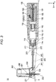
- the cross-sectional view shown in Fig. 3 is a vertical cross-sectional view (an X-Z cross sectional view) of the drug solution administration apparatus 100 and the administration instrument 200.
- the drug solution administration set 10 is used for administering a drug solution into a living body. As illustrated in Fig. 1 , the drug solution administration set 10 includes the drug solution administration apparatus 100 and the administration instrument 200 connectable to the drug solution administration apparatus 100.
- the drug solution administration apparatus 100 and a needle hub unit 230 in the administration instrument 200 are attached to a body surface (skin) H of the user.
- the site of the user body to which the drug solution administration apparatus 100 and the needle hub unit 230 are attached is not particularly limited, and examples thereof include the abdomen and thighs.
- the drug solution administration set 10 is capable of continuously administering a drug solution (not illustrated) filled in a drug solution container 110 included in the drug solution administration apparatus 100 into a living body over a relatively long period of time (for example, about several minutes to several hours) by a pressing action provided by the pusher 130 and a gasket 140. Note that the drug solution administration set 10 may intermittently administer a drug solution into a living body.
- the drug solution administration apparatus 100 includes: a drug solution container 110 that is filled with a drug solution and includes an opening through which the drug solution can be discharged, the opening being formed at a distal end 112; a gasket 140 that is slidable on an inner wall of the drug solution container 110 and is to push out the drug solution contained in the drug solution container 110; a pusher 130 that is capable of pressing the gasket 140; a housing 120 that houses the drug solution container 110 and the pusher 130; a drive mechanism 150 that moves forward the pusher 130 toward the distal end of the drug solution container 110; a switch 160 that is turned on when being in contact with the pusher 130 and is turned off when being in non-contact with the pusher 130; and a control unit 170 that controls operations of the drive mechanism 150 and checks the state of the switch 160.
- the distal end of the drug solution container 110 protrudes from the housing 120 as described later.
- the housing 120 is formed of a box-shaped member having a housing space formed therein.
- a chassis 127 illustrated in Fig. 5 is housed inside the housing 120.
- a window part 123a is formed on a top surface 123 of the housing 120 so that the inside of the housing 120 can be visually recognized from the outside of the housing 120.
- the window part 123a is formed by providing a transparent or translucent portion in a part of the housing 120.
- a sheet-like sticking part (not illustrated) that can be stuck on the body surface H of the user is provided.
- a peelable protective sheet is attached to the sticking surface of the sticking part.
- the drug solution container 110, the pusher 130, the gasket 140, the drive mechanism 150, the control unit 170, and the power supply unit 180 are disposed in the chassis 127.
- the drug solution container 110 is formed of a tubular body including an inner cavity 111 that is to be filled with a drug solution.
- the gasket 140 is disposed in the inner cavity 111 of the drug solution container 110.
- the gasket 140 can be made of, for example, a rubber material or a resin material such as an elastomer.
- the gasket 140 liquid-tightly seals the proximal end side of the gasket 140 by bringing the outer periphery of the gasket 140 into close contact with the inner peripheral surface of the drug solution container 110 in a liquid-tight manner.
- the drug solution container 110 is formed of a socalled prefilled type drug solution container. Therefore, the drug solution is filled in advance in the inner cavity 111 of the drug solution container 110.
- the drug solution include protein preparations, narcotic analgesics, and diuretics.
- the pusher 130 is configured to be movable forward, as caused by the drive mechanism 150, with respect to the drug solution container 110 toward the distal end side (lower side in Fig. 3 ) of the drug solution container 110.
- the pusher 130 moves the gasket 140 disposed in the drug solution container 110 toward the distal end 112 of the drug solution container 110, thereby pushing the drug solution from the inner cavity 111 of the drug solution container 110 toward the needle tube 220.
- the pusher 130 is separated from the gasket 140 by a distance greater than a predetermined distance L1 before the drug solution administration apparatus 100 is in use so that there is still a gap between the pusher 130 and the gasket 140 after the pusher 130 moves forward by the predetermined distance L1 in an operation test, which will be described later.
- the gasket 140 is configured to be contractible in a direction (axial direction of the pusher 130) in which the pusher 130 moves forward when the pusher 130 moves forward in a state where the gasket 140 is pressed against the distal end inner wall of the drug solution container 110.
- the gasket 140 can be made of, for example, a rubber material or a flexible resin material such as an elastomer.
- a seal member 114 that prevents leakage of a drug solution is disposed at the opening (discharge port) of the drug solution container 110.
- the opening of the drug solution container 110 is disposed so as to protrude outward from the housing 120.
- an attachment 115 to be connected to a connector 210, which will be described later (see Fig. 1 ) is attached to the distal end protruding from the housing 120.
- Fig. 8 schematically illustrates a control system of the control unit 170.
- the control unit 170 controls operations of the drive mechanism 150, the switch 160, the power supply unit 180, and a notification unit 190 in a centralized manner.
- the control unit 170 can be formed of, for example, a known microcomputer (electronic circuit element) in which a CPU, a RAM, a ROM, and the like are mounted.
- the switch 160 is disposed on the inner side of the top surface 123 of the housing 120.
- the switch 160 includes a connection part 161 connected to the housing 120 and a detection end 163.
- the switch 160 is turned on when the pusher 130 comes into contact with the detection end 163.
- the switch 160 is turned off when the detection end 163 and the pusher 130 become out of contact with each other.
- the switch 160 can be formed of, for example, a known contact-type sensor that transmits a predetermined electric signal when the pusher 130 comes into contact with the detection end 163.
- the control unit 170 is capable of detecting whether the switch 160 is on or off on the basis of presence or absence of a received electric signal transmitted by the switch 160.
- the switch 160 is not particularly limited to any specific configuration (shape, structure, arrangement, and the like) as long as the switch can be turned on or off depending on the contact or non-contact state with the pusher 130.
- the power supply unit 180 can be formed of, for example, a known battery or the like.
- the notification unit 190 notifies the user that delivery of the drug solution has been completed.
- the notification unit 190 can be formed of, for example, a speaker or the like that produces voices or sounds.
- the notification unit 190 can be disposed at any position in the housing 120.
- the drive mechanism 150 includes a motor 151 that receives a drive current from the power supply unit 180 to generate a rotational driving force, a deceleration mechanism 153 including gears or the like for transmitting the rotational driving force of the motor 151, and a feed screw 155 connected to the deceleration mechanism 153.
- the feed screw 155 converts a rotary motion transmitted from the deceleration mechanism 153 into a linear motion to move forward the pusher 130 in the axial direction (X direction).
- the pusher 130 includes a tubular body 131 and a recess 132 extending along the axial direction of the pusher 130.
- the recess 132 is provided as a slit 133 obtained by cutting a distal end of the pusher 130.
- the recess 132 extends to the distal end opening of the tubular body 131. Note that no particular limitation is imposed on the shape of the recess 132 (slit 133), its specific position formed in the tubular body 131, and the like.
- the pusher 130 is disposed in the housing 120 in the state where the pusher 130 is in non-contact with the detection end 163 of the switch 160.
- the switch 160 is disposed on the proximal end side of the drug solution container 110 and near the proximal end of the drug solution container 110, and is placed in the recess 132, thereby maintaining the state where the switch 160 is in non-contact with the tubular body 131.
- the switch 160 comes into contact with the proximal end 132a of the recess 132 and is turned on (See Figs. 11 and 12 ).
- the pusher 130 maintains contact with the switch 160 while the drug solution is administered. As illustrated in Fig. 13 , the pusher 130 becomes out of contact with the switch 160 when, or immediately before, the administration of the drug solution is completed.
- the method of controlling the drug solution administration apparatus 100 includes an operation test (S101), checking whether the switch is on (S102), an administration start operation (S103), a notification operation (S104), checking whether the switch is off (S105), and an administration completion operation (106).
- the control unit 170 conducts an operation test of checking whether the switch 160 is turned on when the pusher 130 is moved forward by a predetermined distance L1 (see Figs. 10 and 11 ). After confirming that the switch 160 is turned on in the operation test, the control unit 170 performs the administration start operation for administering the drug solution.
- control unit 170 The following specifically describes the control method performed by the control unit 170 with reference to Figs. 9 to 13 .
- the switch 160 and the pusher 130 are disposed to be in non-contact with each other.
- a gap is provided between the proximal end 141 of the gasket 140 and the distal end 131a of the pusher 130.
- control unit 170 Before administration of a drug solution is started, the control unit 170 conducts an operation test (S101). As illustrated in Fig. 11 , the control unit 170 moves forward the pusher 130 by a predetermined distance L1.
- control unit 170 may perform, prior to the operation test, a priming operation of filling the needle tube 220 and the solution delivery tube 240 (see Fig. 3 ) with the drug solution before the living body of the user is punctured with the needle tube 220 of the administration instrument 200.
- the "administration start operation" described in the present embodiment means an operation for starting administration of a drug solution into the body of the user. Therefore, the priming operation is not included in the administration start operation.
- the control unit 170 checks the state of the switch 160 (S102). If it is confirmed that the switch 160 is turned on (S102: YES), the control unit 170 performs the administration start operation for administering a drug solution (S103). Note that the control unit 170 may start the administration start operation when a certain time period has passed after detecting that the switch 160 is turned on. In other words, the control unit 170 may not necessarily start administering the drug solution immediately after the switch 160 is turned on.
- control unit 170 determines that a malfunction has occurred in the switch 160 and makes notification of an error (S104). After making notification of an error, the control unit 170 proceeds with the operation test. Note that the control unit 170 may stop the operation test after making notification of an error.
- the pusher 130 moves forward the gasket 140 disposed on the distal end side of the pusher 130 toward the distal end 112 of the drug solution container 110, thereby delivering the drug solution to the administration instrument 200 (see Fig. 3 ).
- the pusher 130 maintains contact with the switch 160 while the drug solution is administered.
- the control unit 170 performs the completion operation of administration of the drug solution, triggered by turning-off of the switch 160 (S106). As illustrated in Fig. 13 , the proximal end 131b of the pusher 130 comes to the distal end side beyond the detection end 163 of the switch 160, whereby the pusher 130 and the switch 160 become out of contact with each other, and the switch 160 is turned off.
- the pusher 130 and the switch 160 may become out of contact with each other upon completion of administration of the drug solution or immediately before completion of administration of the drug solution.
- the switch 160 may fail to be turned off even when the gasket 140 has moved forward until its distal end is pressed against an inner wall of the distal end of the drug solution container 110.
- the control unit 170 continues to move forward the pusher 130 unless the switch 160 is turned off. Therefore, the administration operation by the drug solution administration apparatus 100 is not stopped.
- the pusher 130 and the switch 160 are configured to become out of contact with each other immediately before completion of administration of a drug solution, the pusher 130 and the switch 160 are enabled to become out of contact with each other more reliably when the pusher 130 is moved forward by a predetermined distance even in cases where installation, dimensions, or the like of the individual components is less accurate.
- control unit 170 continues the administration operation.
- the following describes the administration instrument 200.
- the administration instrument 200 includes a connector 210, a needle hub unit 230, a solution delivery tube 240, and a puncture aid 250.
- the connector 210 includes a connector body 211 connectable to the attachment 115 attached to the drug solution container 110 and a communication part 215 communicable with the inner cavity 111 of the drug solution container 110.
- the communication part 215 of the connector 210 is formed of a hollow needle tube capable of passing through the seal member 114 disposed in the drug solution container 110.
- the needle hub unit 230 includes a needle holding part 231 that holds the needle tube 220 and a communication path 233 that communicates with the inner cavity of the needle tube 220.
- the solution delivery tube 240 includes a first end 241 connected to the needle hub unit 230, a second end 242 connected to the connector 210, and an intermediate portion 243 extending between the first end 241 and the second end 242.
- the solution delivery tube 240 delivers the drug solution from the inner cavity 111 of the drug solution container 110 to the needle tube 220 via the communication part 215 of the connector 210 and the communication path 233 of the needle hub unit 230.
- the puncture aid 250 When the drug solution is going to be delivered to the user, the puncture aid 250 is attached to the needle hub unit 230.
- the puncture aid 250 holds an introducer needle (inner needle) 251.
- the introducer needle 251 protrudes from the tip of the needle tube 220.
- the puncture aid 250 is removed from the needle hub unit 230.
- the introducer needle 251 is removed from the inner cavity of the needle tube 220.
- the needle tube 220 is left in the living body.
- the pusher 130 and the gasket 140 in the drug solution administration apparatus 100 move forward inside the drug solution container 110, whereby the drug solution filled in the drug solution container 110 is delivered to the inner cavity of the needle tube 220 via the solution delivery tube 240.
- the introducer needle 251 can be formed of, for example, a metal needle.
- the needle tube 220 can be formed of, for example, a tubular member (cannula) made of resin.
- the administration instrument 200 can be configured as a patch-type instrument to be attached to the body surface H of the user before use.
- a sheet-like sticking part (not illustrated) that can be stuck on the body surface can be provided.
- a peelable protective sheet can be attached to the sticking surface of the sticking part provided on the bottom surface.
- the drug solution administration apparatus 100 is a drug solution administration apparatus for administering a drug solution
- the drug solution administration apparatus including: the drug solution container 110 that is filled with a drug solution and includes an opening through which the drug solution can be discharged, the opening being formed at a distal end of the drug solution container 110; the gasket 140 that is slidable on an inner wall of the drug solution container 110 and is to push out the drug solution contained in the drug solution container 110; the pusher 130 that is capable of pressing the gasket 140; the housing 120 that houses the drug solution container 110 and the pusher 130; the drive mechanism 150 that moves forward the pusher 130 toward the distal end 112 of the drug solution container 110; the switch 160 that is turned on when being in contact with the pusher and is turned off when being non-contact with the pusher 130; and the control unit 170 that controls operations of the drive mechanism 150 and checks the state of the switch 160, in which before the drug solution administration apparatus 100 is in use, the pusher 130 is disposed in the housing 120 in a state where the
- the drug solution administration apparatus 100 configured as above makes it possible to prevent the occurrence of contact failure and the like due to a decrease in the recovering force of the switch 160 because the switch 160 and the pusher 130 are disposed in the state of non-contact with each other before the drug solution administration apparatus 100 is in use.
- the drug solution administration apparatus 100 is capable of effectively preventing a decrease in the recovering force of the switch 160 in a case where, for example, the drug solution container 110 is a prefilled-type drug solution container and is stored under refrigeration over a long period of time.
- the drug solution administration apparatus 100 is capable of detecting an operation failure of the switch 160 prior to an administration start operation for administering a drug solution because the drug solution administration apparatus 100 is configured to perform the administration start operation after confirming that the switch 160 is turned on in an operation test.
- the pusher 130 maintains contact with the switch 160 while the drug solution is administered, and becomes out of contact with the switch 160 when, or immediately before, the administration of the drug solution is completed.
- the control unit 170 performs the completion operation of administration of the drug solution, triggered by turning-off of the switch 160. Therefore, the drug solution administration apparatus 100 can perform the administration completion operation at an appropriate timing on the basis of the switching between the state where the switch 160 and the pusher 130 are in contact with each other and the state where the switch 160 and the pusher 130 are in non-contact with each other.
- the pusher 130 includes the recess 132 extending along the axial direction of the pusher 130.
- the switch 160 is disposed in the recess 132 and maintains the state of non-contact with the pusher 130, and when the pusher 130 moves forward by a predetermined distance L1, the switch 160 comes into contact with the proximal end 132a of the recess 132 and is turned on.
- the switch 160 is disposed in the recess 132, whereby the drug solution administration apparatus 100 can more reliably prevent the pusher 130 and the switch 160 from coming into contact with each other before the drug solution administration apparatus 100 is in use.
- the switch 160 is disposed on the proximal end side of the drug solution container 110 and near the proximal end of the drug solution container 110, and the recess 132 is provided as the slit 133 obtained by cutting a distal end of the pusher 130. Therefore, when the drug solution administration apparatus 100 is assembled, the switch 160 is placed along the slit 133, whereby the pusher 130 and the switch 160 can be more reliably prevented from coming into contact with each other during the assembly work.
- the pusher 130 is separated from the gasket 140 by a distance greater than a predetermined distance L1 before the drug solution administration apparatus 100 is in use so that there is still a gap between the pusher 130 and the gasket 140 after the pusher 130 moves forward by the predetermined distance L1. Therefore, the gasket 140 is not pressed by the pusher 130 during the operation test, thereby preventing a drug solution from being administered mistakenly.
- the drug solution administration set 10 includes the drug solution administration apparatus 100 and the administration instrument 200 connectable to the drug solution administration apparatus 100.
- the administration instrument 200 includes: the connector 210 that includes the communication part 215 communicable with the inner cavity 111 of the drug solution container 110 and is connectable to the drug solution administration apparatus 100; the needle tube 220 that is to puncture a living body; the needle hub unit 230 that includes the needle holding part 231 holding the needle tube 220 and the communication path 233 communicating with the inner cavity of the needle tube 220; and the solution delivery tube 240 that includes the first end 241 connected to the needle hub unit 230 and the second end 242 connected to the connector 210, and that is capable of delivering a drug solution from the inner cavity 111 of the drug solution container 110 to the needle tube 220 via the communication part 215 of the connector 210 and the communication path 233 of the needle hub unit 230.
- the drug solution administration set 10 as configured above enables the control unit 170 to accurately detect completion of administration of a drug solution on the basis of the state of contact between the pusher 130 and the switch 160 in the drug solution administration apparatus 100, thereby making it possible to administer an appropriate amount of the drug solution into the living body of the user.
Landscapes
- Health & Medical Sciences (AREA)
- Vascular Medicine (AREA)
- Engineering & Computer Science (AREA)
- Anesthesiology (AREA)
- Biomedical Technology (AREA)
- Heart & Thoracic Surgery (AREA)
- Hematology (AREA)
- Life Sciences & Earth Sciences (AREA)
- Animal Behavior & Ethology (AREA)
- General Health & Medical Sciences (AREA)
- Public Health (AREA)
- Veterinary Medicine (AREA)
- Dermatology (AREA)
- Infusion, Injection, And Reservoir Apparatuses (AREA)
Abstract
Description
- The present invention relates to a drug solution administration apparatus and a drug solution administration set.
- Conventionally, there have been known syringe pump type drug solution administration apparatuses for administering a drug solution filled in a drug solution container to a living body by a pressing action provided by a pusher. A drug solution administration apparatus of this type includes a tubular drug solution container, a pusher that pushes out the drug solution contained in the drug solution container, and a gasket (see, for example,
Patent Literature 1 below). - Patent Literature 1:
JP H9-294807 A - For checking the state of administration of a drug solution filled in the drug solution container, the control unit provided in the drug solution administration apparatus is configured to make a determination. When the pusher moves forward toward the distal end of the drug solution container by a predetermined distance, the control unit checks the state of the switch that is turned on when the switch comes into contact with the pusher. When the switch comes into contact with the pusher and is turned on, the control unit detects that administration of the drug solution has started. When the switch becomes out of contact with the pusher and is turned off, the control unit detects that administration of the drug solution has completed.
- The drug solution administration apparatus may be stored over a predetermined period of time before being used for administering a drug solution. If the pusher and the switch are constantly in contact with each other during such storage, the recovering force of the switch decreases. When the recovering force of the switch decreases, the switch will fail to be turned off even in a state where the load of the pusher is no longer imposed on the switch. As a result, in spite of the fact that the drug solution has been completely administered and the pusher and the switch become out of contact, there is a possibility that the control unit erroneously recognizes that administration of the drug solution is not completed yet and makes an error notification.
- The present invention has been made in view of the above problems, and an object of the present invention is to provide a drug solution administration apparatus and a drug solution administration set in which the control unit can accurately detect completion of administration of a drug solution on the basis of the state of contact between the pusher and the switch.
- The drug solution administration apparatus of the present invention is a drug solution administration apparatus for administering a drug solution, the drug solution administration apparatus including: a drug solution container that is filled with the drug solution and includes an opening through which the drug solution is allowed to be discharged, the opening being formed at a distal end of the drug solution container; a gasket that is slidable on an inner wall of drug solution container and is to push out the drug solution contained in the drug solution container; a pusher that is capable of pressing the gasket; a housing that houses the drug solution container and the pusher; a drive mechanism that moves forward the pusher toward the distal end of the drug solution container; a switch that is turned on when being in contact with the pusher and is turned off when being non-contact with the pusher; and a control unit that controls an operation of the drive mechanism and checks a state of the switch, in which before the drug solution administration apparatus is in use, the pusher is disposed in the housing in a state where the pusher is non-contact with the switch, and the control unit is configured to, prior to start of administration of the drug solution, conduct an operation test of checking whether the switch is turned on when the pusher is moved forward by a predetermined distance and, after it is confirmed that the switch is turned on in the operation test, to perform an administration start operation for administering the drug solution.
- The drug solution administration apparatus and the drug solution administration set according to the present invention enable the control unit to accurately detect completion of administration of a drug solution on the basis of the state of contact between the pusher and the switch.
-
-
Fig. 1 is a side view of a drug solution administration set according to an embodiment of the present invention. -
Fig. 2 is a diagram schematically illustrating a usage example of the drug solution administration set shown inFig. 1 . -
Fig. 3 is a cross-sectional view of the drug solution administration set shown inFig. 1 . -
Fig. 4 is a schematic perspective view of a drug solution administration apparatus. -
Fig. 5 is a plan view schematically illustrating the inside of a housing of the drug solution administration apparatus. -
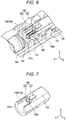
Fig. 6 is a perspective view showing a pusher recess and a switch. -
Fig. 7 is a perspective view showing the pusher. -
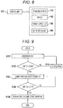
Fig. 8 is a block diagram schematically showing a control system of the drug solution administration apparatus. -
Fig. 9 is a flowchart showing a method of controlling the drug solution administration apparatus. -
Fig. 10 is a cross-sectional view for explaining an operation example of the drug solution administration apparatus. -
Fig. 11 is a cross-sectional view for explaining an operation example of the drug solution administration apparatus. -
Fig. 12 is a cross-sectional view for explaining an operation example of the drug solution administration apparatus. -
Fig. 13 is a cross-sectional view for explaining an operation example of the drug solution administration apparatus. - Embodiments of the present invention will now be described with reference to the accompanying drawings. Note that the following description does not limit the technical scope and the meaning of terms described in the claims. In addition, dimensional ratios in the drawings are exaggerated for convenience of description and may be different from actual ratios.
-
Figs. 1 to 7 are diagrams for explaining a drug solution administration set 10, a drugsolution administration apparatus 100, and anadministration instrument 200 according to an embodiment of the present invention. In the drawings, an arrow X indicates the "longitudinal direction (axial direction of a pusher 130)" of the drugsolution administration apparatus 100, an arrow Y indicates the "width direction (depth direction)" of the drugsolution administration apparatus 100, and an arrow Z indicates the "height direction" of the drugsolution administration apparatus 100. The cross-sectional view shown inFig. 3 is a vertical cross-sectional view (an X-Z cross sectional view) of the drugsolution administration apparatus 100 and theadministration instrument 200. - The drug solution administration set 10 is used for administering a drug solution into a living body. As illustrated in
Fig. 1 , the drug solution administration set 10 includes the drugsolution administration apparatus 100 and theadministration instrument 200 connectable to the drugsolution administration apparatus 100. - As illustrated in
Figs. 2 and3 , when the drug solution administration set 10 is used to administer a drug solution, the drugsolution administration apparatus 100 and aneedle hub unit 230 in theadministration instrument 200 are attached to a body surface (skin) H of the user. The site of the user body to which the drugsolution administration apparatus 100 and theneedle hub unit 230 are attached is not particularly limited, and examples thereof include the abdomen and thighs. - The drug solution administration set 10 is capable of continuously administering a drug solution (not illustrated) filled in a
drug solution container 110 included in the drugsolution administration apparatus 100 into a living body over a relatively long period of time (for example, about several minutes to several hours) by a pressing action provided by thepusher 130 and agasket 140. Note that the drug solution administration set 10 may intermittently administer a drug solution into a living body. - As illustrated in
Figs. 3 and5 , the drugsolution administration apparatus 100 includes: adrug solution container 110 that is filled with a drug solution and includes an opening through which the drug solution can be discharged, the opening being formed at adistal end 112; agasket 140 that is slidable on an inner wall of thedrug solution container 110 and is to push out the drug solution contained in thedrug solution container 110; apusher 130 that is capable of pressing thegasket 140; ahousing 120 that houses thedrug solution container 110 and thepusher 130; adrive mechanism 150 that moves forward thepusher 130 toward the distal end of thedrug solution container 110; aswitch 160 that is turned on when being in contact with thepusher 130 and is turned off when being in non-contact with thepusher 130; and acontrol unit 170 that controls operations of thedrive mechanism 150 and checks the state of theswitch 160. Note that the distal end of thedrug solution container 110 protrudes from thehousing 120 as described later. - The
housing 120 is formed of a box-shaped member having a housing space formed therein. Achassis 127 illustrated inFig. 5 is housed inside thehousing 120. - As illustrated in
Fig. 4 , awindow part 123a is formed on atop surface 123 of thehousing 120 so that the inside of thehousing 120 can be visually recognized from the outside of thehousing 120. Thewindow part 123a is formed by providing a transparent or translucent portion in a part of thehousing 120. - On a
bottom surface 121 of the housing, a sheet-like sticking part (not illustrated) that can be stuck on the body surface H of the user is provided. In an initial state before the drugsolution administration apparatus 100 is attached to the user, a peelable protective sheet is attached to the sticking surface of the sticking part. - As illustrated in
Fig. 5 , thedrug solution container 110, thepusher 130, thegasket 140, thedrive mechanism 150, thecontrol unit 170, and thepower supply unit 180 are disposed in thechassis 127. - The
drug solution container 110 is formed of a tubular body including aninner cavity 111 that is to be filled with a drug solution. Thegasket 140 is disposed in theinner cavity 111 of thedrug solution container 110. Thegasket 140 can be made of, for example, a rubber material or a resin material such as an elastomer. The gasket 140 liquid-tightly seals the proximal end side of thegasket 140 by bringing the outer periphery of thegasket 140 into close contact with the inner peripheral surface of thedrug solution container 110 in a liquid-tight manner. - The
drug solution container 110 is formed of a socalled prefilled type drug solution container. Therefore, the drug solution is filled in advance in theinner cavity 111 of thedrug solution container 110. Examples of the drug solution include protein preparations, narcotic analgesics, and diuretics. - The
pusher 130 is configured to be movable forward, as caused by thedrive mechanism 150, with respect to thedrug solution container 110 toward the distal end side (lower side inFig. 3 ) of thedrug solution container 110. Thepusher 130 moves thegasket 140 disposed in thedrug solution container 110 toward thedistal end 112 of thedrug solution container 110, thereby pushing the drug solution from theinner cavity 111 of thedrug solution container 110 toward theneedle tube 220. - As illustrated in
Figs. 10 and 11 , thepusher 130 is separated from thegasket 140 by a distance greater than a predetermined distance L1 before the drugsolution administration apparatus 100 is in use so that there is still a gap between thepusher 130 and thegasket 140 after thepusher 130 moves forward by the predetermined distance L1 in an operation test, which will be described later. - In the present embodiment, the
gasket 140 is configured to be contractible in a direction (axial direction of the pusher 130) in which thepusher 130 moves forward when thepusher 130 moves forward in a state where thegasket 140 is pressed against the distal end inner wall of thedrug solution container 110. Thegasket 140 can be made of, for example, a rubber material or a flexible resin material such as an elastomer. - As illustrated in
Fig. 3 , aseal member 114 that prevents leakage of a drug solution is disposed at the opening (discharge port) of thedrug solution container 110. The opening of thedrug solution container 110 is disposed so as to protrude outward from thehousing 120. On thedrug solution container 110, anattachment 115 to be connected to aconnector 210, which will be described later (seeFig. 1 ), is attached to the distal end protruding from thehousing 120. -
Fig. 8 schematically illustrates a control system of thecontrol unit 170. Thecontrol unit 170 controls operations of thedrive mechanism 150, theswitch 160, thepower supply unit 180, and anotification unit 190 in a centralized manner. Thecontrol unit 170 can be formed of, for example, a known microcomputer (electronic circuit element) in which a CPU, a RAM, a ROM, and the like are mounted. - As illustrated in
Figs. 3 and6 , theswitch 160 is disposed on the inner side of thetop surface 123 of thehousing 120. Theswitch 160 includes aconnection part 161 connected to thehousing 120 and adetection end 163. Theswitch 160 is turned on when thepusher 130 comes into contact with thedetection end 163. Theswitch 160 is turned off when thedetection end 163 and thepusher 130 become out of contact with each other. - The
switch 160 can be formed of, for example, a known contact-type sensor that transmits a predetermined electric signal when thepusher 130 comes into contact with thedetection end 163. Thecontrol unit 170 is capable of detecting whether theswitch 160 is on or off on the basis of presence or absence of a received electric signal transmitted by theswitch 160. Note that theswitch 160 is not particularly limited to any specific configuration (shape, structure, arrangement, and the like) as long as the switch can be turned on or off depending on the contact or non-contact state with thepusher 130. - The
power supply unit 180 can be formed of, for example, a known battery or the like. - The
notification unit 190 notifies the user that delivery of the drug solution has been completed. Thenotification unit 190 can be formed of, for example, a speaker or the like that produces voices or sounds. Thenotification unit 190 can be disposed at any position in thehousing 120. - As illustrated in
Fig. 5 , thedrive mechanism 150 includes amotor 151 that receives a drive current from thepower supply unit 180 to generate a rotational driving force, adeceleration mechanism 153 including gears or the like for transmitting the rotational driving force of themotor 151, and afeed screw 155 connected to thedeceleration mechanism 153. - The
feed screw 155 converts a rotary motion transmitted from thedeceleration mechanism 153 into a linear motion to move forward thepusher 130 in the axial direction (X direction). - As illustrated in
Figs. 6 and 7 , thepusher 130 includes atubular body 131 and arecess 132 extending along the axial direction of thepusher 130. - The
recess 132 is provided as aslit 133 obtained by cutting a distal end of thepusher 130. Therecess 132 extends to the distal end opening of thetubular body 131. Note that no particular limitation is imposed on the shape of the recess 132 (slit 133), its specific position formed in thetubular body 131, and the like. - Before the drug
solution administration apparatus 100 is in use, thepusher 130 is disposed in thehousing 120 in the state where thepusher 130 is in non-contact with thedetection end 163 of theswitch 160. Specifically, as illustrated inFig. 6 , theswitch 160 is disposed on the proximal end side of thedrug solution container 110 and near the proximal end of thedrug solution container 110, and is placed in therecess 132, thereby maintaining the state where theswitch 160 is in non-contact with thetubular body 131. When thepusher 130 moves forward by a predetermined distance L1, theswitch 160 comes into contact with theproximal end 132a of therecess 132 and is turned on (SeeFigs. 11 and12 ). - As illustrated in
Fig. 12 , thepusher 130 maintains contact with theswitch 160 while the drug solution is administered. As illustrated inFig. 13 , thepusher 130 becomes out of contact with theswitch 160 when, or immediately before, the administration of the drug solution is completed. - Now, a method of controlling the drug
solution administration apparatus 100 according to the present embodiment will be described. - As shown in
Fig. 9 , the method of controlling the drugsolution administration apparatus 100 includes an operation test (S101), checking whether the switch is on (S102), an administration start operation (S103), a notification operation (S104), checking whether the switch is off (S105), and an administration completion operation (106). - In the present embodiment, before the drug
solution administration apparatus 100 starts administering a drug solution, thecontrol unit 170 conducts an operation test of checking whether theswitch 160 is turned on when thepusher 130 is moved forward by a predetermined distance L1 (seeFigs. 10 and 11 ). After confirming that theswitch 160 is turned on in the operation test, thecontrol unit 170 performs the administration start operation for administering the drug solution. - The following specifically describes the control method performed by the
control unit 170 with reference toFigs. 9 to 13 . - As illustrated in
Fig. 10 , before administration of a drug solution is started, theswitch 160 and thepusher 130 are disposed to be in non-contact with each other. In addition, a gap is provided between theproximal end 141 of thegasket 140 and thedistal end 131a of thepusher 130. - Before administration of a drug solution is started, the
control unit 170 conducts an operation test (S101). As illustrated inFig. 11 , thecontrol unit 170 moves forward thepusher 130 by a predetermined distance L1. - Note that the
control unit 170 may perform, prior to the operation test, a priming operation of filling theneedle tube 220 and the solution delivery tube 240 (seeFig. 3 ) with the drug solution before the living body of the user is punctured with theneedle tube 220 of theadministration instrument 200. The "administration start operation" described in the present embodiment means an operation for starting administration of a drug solution into the body of the user. Therefore, the priming operation is not included in the administration start operation. - When the
pusher 130 is moved forward by a predetermined distance L1, thecontrol unit 170 checks the state of the switch 160 (S102). If it is confirmed that theswitch 160 is turned on (S102: YES), thecontrol unit 170 performs the administration start operation for administering a drug solution (S103). Note that thecontrol unit 170 may start the administration start operation when a certain time period has passed after detecting that theswitch 160 is turned on. In other words, thecontrol unit 170 may not necessarily start administering the drug solution immediately after theswitch 160 is turned on. - If it is not confirmed that the
switch 160 is turned on when thepusher 130 is moved forward by a predetermined distance L1 (S102: NO), thecontrol unit 170 determines that a malfunction has occurred in theswitch 160 and makes notification of an error (S104). After making notification of an error, thecontrol unit 170 proceeds with the operation test. Note that thecontrol unit 170 may stop the operation test after making notification of an error. - As illustrated in
Fig. 12 , thepusher 130 moves forward thegasket 140 disposed on the distal end side of thepusher 130 toward thedistal end 112 of thedrug solution container 110, thereby delivering the drug solution to the administration instrument 200 (seeFig. 3 ). Thepusher 130 maintains contact with theswitch 160 while the drug solution is administered. - If it is confirmed that the
switch 160 is turned off (S105: YES), thecontrol unit 170 performs the completion operation of administration of the drug solution, triggered by turning-off of the switch 160 (S106). As illustrated inFig. 13 , theproximal end 131b of thepusher 130 comes to the distal end side beyond thedetection end 163 of theswitch 160, whereby thepusher 130 and theswitch 160 become out of contact with each other, and theswitch 160 is turned off. - Note that the
pusher 130 and theswitch 160 may become out of contact with each other upon completion of administration of the drug solution or immediately before completion of administration of the drug solution. For example, in cases where installation, dimensions, or the like of the individual components such as thedrug solution container 110, thepusher 130, and theswitch 160 is less accurate, theswitch 160 may fail to be turned off even when thegasket 140 has moved forward until its distal end is pressed against an inner wall of the distal end of thedrug solution container 110. Thecontrol unit 170 continues to move forward thepusher 130 unless theswitch 160 is turned off. Therefore, the administration operation by the drugsolution administration apparatus 100 is not stopped. As in the present embodiment, if thepusher 130 and theswitch 160 are configured to become out of contact with each other immediately before completion of administration of a drug solution, thepusher 130 and theswitch 160 are enabled to become out of contact with each other more reliably when thepusher 130 is moved forward by a predetermined distance even in cases where installation, dimensions, or the like of the individual components is less accurate. - If it is not confirmed that the
switch 160 is turned off during the administration operation (S105: NO), thecontrol unit 170 continues the administration operation. - The following describes the
administration instrument 200. - As illustrated in
Figs. 1 and3 , theadministration instrument 200 includes aconnector 210, aneedle hub unit 230, asolution delivery tube 240, and apuncture aid 250. - As illustrated in
Fig. 3 , theconnector 210 includes aconnector body 211 connectable to theattachment 115 attached to thedrug solution container 110 and acommunication part 215 communicable with theinner cavity 111 of thedrug solution container 110. Thecommunication part 215 of theconnector 210 is formed of a hollow needle tube capable of passing through theseal member 114 disposed in thedrug solution container 110. - As illustrated in
Fig. 3 , theneedle hub unit 230 includes aneedle holding part 231 that holds theneedle tube 220 and acommunication path 233 that communicates with the inner cavity of theneedle tube 220. - As illustrated in
Fig. 3 , thesolution delivery tube 240 includes afirst end 241 connected to theneedle hub unit 230, asecond end 242 connected to theconnector 210, and anintermediate portion 243 extending between thefirst end 241 and thesecond end 242. - The
solution delivery tube 240 delivers the drug solution from theinner cavity 111 of thedrug solution container 110 to theneedle tube 220 via thecommunication part 215 of theconnector 210 and thecommunication path 233 of theneedle hub unit 230. - When the drug solution is going to be delivered to the user, the
puncture aid 250 is attached to theneedle hub unit 230. Thepuncture aid 250 holds an introducer needle (inner needle) 251. As illustrated inFigs. 1 and3 , in a state where thepuncture aid 250 is attached to theneedle hub unit 230, theintroducer needle 251 protrudes from the tip of theneedle tube 220. By puncturing the living body with theneedle tube 220 in a state where theintroducer needle 251 is inserted through theneedle tube 220, the user can insert theneedle tube 220 into the living body while preventing breakage or the like of theneedle tube 220. - After the living body is punctured with the
needle tube 220, thepuncture aid 250 is removed from theneedle hub unit 230. When thepuncture aid 250 is removed from theneedle hub unit 230, theintroducer needle 251 is removed from the inner cavity of theneedle tube 220. - After the
puncture aid 250 is removed from theneedle hub unit 230, theneedle tube 220 is left in the living body. Thepusher 130 and thegasket 140 in the drugsolution administration apparatus 100 move forward inside thedrug solution container 110, whereby the drug solution filled in thedrug solution container 110 is delivered to the inner cavity of theneedle tube 220 via thesolution delivery tube 240. - The
introducer needle 251 can be formed of, for example, a metal needle. Theneedle tube 220 can be formed of, for example, a tubular member (cannula) made of resin. - As with the drug
solution administration apparatus 100, theadministration instrument 200 can be configured as a patch-type instrument to be attached to the body surface H of the user before use. On the bottom surface of theneedle hub unit 230 of theadministration instrument 200, a sheet-like sticking part (not illustrated) that can be stuck on the body surface can be provided. In an initial state before theadministration instrument 200 is attached to the user, a peelable protective sheet can be attached to the sticking surface of the sticking part provided on the bottom surface. - As described above, the drug solution administration apparatus 100 according to the present embodiment is a drug solution administration apparatus for administering a drug solution, the drug solution administration apparatus including: the drug solution container 110 that is filled with a drug solution and includes an opening through which the drug solution can be discharged, the opening being formed at a distal end of the drug solution container 110; the gasket 140 that is slidable on an inner wall of the drug solution container 110 and is to push out the drug solution contained in the drug solution container 110; the pusher 130 that is capable of pressing the gasket 140; the housing 120 that houses the drug solution container 110 and the pusher 130; the drive mechanism 150 that moves forward the pusher 130 toward the distal end 112 of the drug solution container 110; the switch 160 that is turned on when being in contact with the pusher and is turned off when being non-contact with the pusher 130; and the control unit 170 that controls operations of the drive mechanism 150 and checks the state of the switch 160, in which before the drug solution administration apparatus 100 is in use, the pusher 130 is disposed in the housing 120 in a state where the pusher 130 is non-contact with the switch 160, and the control unit 170 is configured to, prior to start of administration of a drug solution, conduct an operation test of checking whether the switch 160 is turned on when the pusher 130 is moved forward by a predetermined distance L1 and, after it is confirmed that the switch 160 is turned on in the operation test, to perform an administration start operation for administering the drug solution.
- The drug
solution administration apparatus 100 configured as above makes it possible to prevent the occurrence of contact failure and the like due to a decrease in the recovering force of theswitch 160 because theswitch 160 and thepusher 130 are disposed in the state of non-contact with each other before the drugsolution administration apparatus 100 is in use. The drugsolution administration apparatus 100 is capable of effectively preventing a decrease in the recovering force of theswitch 160 in a case where, for example, thedrug solution container 110 is a prefilled-type drug solution container and is stored under refrigeration over a long period of time. In addition, the drugsolution administration apparatus 100 is capable of detecting an operation failure of theswitch 160 prior to an administration start operation for administering a drug solution because the drugsolution administration apparatus 100 is configured to perform the administration start operation after confirming that theswitch 160 is turned on in an operation test. - The
pusher 130 maintains contact with theswitch 160 while the drug solution is administered, and becomes out of contact with theswitch 160 when, or immediately before, the administration of the drug solution is completed. Thecontrol unit 170 performs the completion operation of administration of the drug solution, triggered by turning-off of theswitch 160. Therefore, the drugsolution administration apparatus 100 can perform the administration completion operation at an appropriate timing on the basis of the switching between the state where theswitch 160 and thepusher 130 are in contact with each other and the state where theswitch 160 and thepusher 130 are in non-contact with each other. - In addition, the
pusher 130 includes therecess 132 extending along the axial direction of thepusher 130. Before the operation test is started, theswitch 160 is disposed in therecess 132 and maintains the state of non-contact with thepusher 130, and when thepusher 130 moves forward by a predetermined distance L1, theswitch 160 comes into contact with theproximal end 132a of therecess 132 and is turned on. Theswitch 160 is disposed in therecess 132, whereby the drugsolution administration apparatus 100 can more reliably prevent thepusher 130 and theswitch 160 from coming into contact with each other before the drugsolution administration apparatus 100 is in use. - The
switch 160 is disposed on the proximal end side of thedrug solution container 110 and near the proximal end of thedrug solution container 110, and therecess 132 is provided as theslit 133 obtained by cutting a distal end of thepusher 130. Therefore, when the drugsolution administration apparatus 100 is assembled, theswitch 160 is placed along theslit 133, whereby thepusher 130 and theswitch 160 can be more reliably prevented from coming into contact with each other during the assembly work. - The
pusher 130 is separated from thegasket 140 by a distance greater than a predetermined distance L1 before the drugsolution administration apparatus 100 is in use so that there is still a gap between thepusher 130 and thegasket 140 after thepusher 130 moves forward by the predetermined distance L1. Therefore, thegasket 140 is not pressed by thepusher 130 during the operation test, thereby preventing a drug solution from being administered mistakenly. - The drug solution administration set 10 includes the drug
solution administration apparatus 100 and theadministration instrument 200 connectable to the drugsolution administration apparatus 100. Theadministration instrument 200 includes: theconnector 210 that includes thecommunication part 215 communicable with theinner cavity 111 of thedrug solution container 110 and is connectable to the drugsolution administration apparatus 100; theneedle tube 220 that is to puncture a living body; theneedle hub unit 230 that includes theneedle holding part 231 holding theneedle tube 220 and thecommunication path 233 communicating with the inner cavity of theneedle tube 220; and thesolution delivery tube 240 that includes thefirst end 241 connected to theneedle hub unit 230 and thesecond end 242 connected to theconnector 210, and that is capable of delivering a drug solution from theinner cavity 111 of thedrug solution container 110 to theneedle tube 220 via thecommunication part 215 of theconnector 210 and thecommunication path 233 of theneedle hub unit 230. - The drug solution administration set 10 as configured above enables the
control unit 170 to accurately detect completion of administration of a drug solution on the basis of the state of contact between thepusher 130 and theswitch 160 in the drugsolution administration apparatus 100, thereby making it possible to administer an appropriate amount of the drug solution into the living body of the user. - The drug solution administration apparatus and the drug solution administration set according to the present invention have been described above by means of embodiments. However, the present invention is not limited to the individual configurations described above but can be modified as appropriate on the basis of descriptions in the claims.
- The present application is based on
Japanese Patent Application No. 2019-065710 filed on March 29, 2019 -
- 10
- Drug solution administration set
- 100
- Drug solution administration apparatus
- 110
- Drug solution container
- 120
- Housing
- 130
- Pusher
- 131
- Tubular body
- 132
- Recess
- 132a
- Proximal end of recess
- 133
- Slit
- 140
- Gasket
- 141
- Proximal end of gasket
- 150
- Drive mechanism
- 160
- Switch
- 161
- Connection part
- 163
- Detection end
- 200
- Administration instrument
- 210
- Connector
- 215
- Communication part
- 220
- Needle tube
- 230
- Needle hub unit
- 231
- Needle holding part
- 233
- Communication path
- 240
- Solution delivery tube
- 241
- First end
- 242
- Second end
- 250
- Puncture aid
- H
- Body surface
- L1
- Predetermined distance
Claims (6)
- A drug solution administration apparatus for administering a drug solution, the drug solution administration apparatus comprising:a drug solution container that is filled with the drug solution and includes an opening through which the drug solution is allowed to be discharged, the opening being formed at a distal end of the drug solution container;a gasket that is slidable on an inner wall of drug solution container and is to push out the drug solution contained in the drug solution container;a pusher that is capable of pressing the gasket;a housing that houses the drug solution container and the pusher;a drive mechanism that moves forward the pusher toward the distal end of the drug solution container;a switch that is turned on when being in contact with the pusher and is turned off when being non-contact with the pusher; anda control unit that controls an operation of the drive mechanism and checks a state of the switch, whereinbefore the drug solution administration apparatus is in use, the pusher is disposed in the housing in a state where the pusher is non-contact with the switch, andthe control unit is configured to, prior to start of administration of the drug solution, conduct an operation test of checking whether the switch is turned on when the pusher is moved forward by a predetermined distance and, after it is confirmed that the switch is turned on in the operation test, to perform an administration start operation for administering the drug solution.
- The drug solution administration apparatus according to claim 1, whereinthe pusher maintains contact with the switch while the drug solution is administered, and becomes out of contact with the switch when, or immediately before, administration of the drug solution is completed, andthe control unit performs a completion operation of administration of the drug solution, triggered by turning-off of the switch.
- The drug solution administration apparatus according to claim 1 or 2, whereinthe pusher includes a recess extending along an axial direction of the pusher, andbefore the operation test is started, the switch is disposed in the recess and maintains a state of non-contact with the pusher, and when the pusher moves forward by the predetermined distance, the switch comes into contact with a proximal end of the recess and is turned on.
- The drug solution administration apparatus according to claim 3, whereinthe switch is disposed on a proximal end side of the drug solution container and near the proximal end of the drug solution container, andthe recess is provided as a slit obtained by cutting a distal end of the pusher.
- The drug solution administration apparatus according to any one of claims 1 to 4, wherein
the pusher is separated from the gasket by a distance greater than the predetermined distance before the drug solution administration apparatus is in used so that there is still a gap between the pusher and the gasket after the pusher moves forward by the predetermined distance. - A drug solution administration set comprising:the drug solution administration apparatus according to any one of claims 1 to 5; andan administration instrument connectable to the drug solution administration apparatus, whereinthe administration instrument comprises:a connector that includes a communication part communicable with an inner cavity of the drug solution container and is connectable to the drug solution administration apparatus;a needle tube that is to puncture a living body;a needle hub unit that includes a needle holding part holding the needle tube and a communication path communicating with an inner cavity of the needle tube; anda tube that includes a first end connected to the needle hub unit and a second end connected to the connector, and that is capable of delivering the drug solution from the inner cavity of the drug solution container to the needle tube via the communication part of the connector and the communication path of the needle hub unit.
Applications Claiming Priority (2)
| Application Number | Priority Date | Filing Date | Title |
|---|---|---|---|
| JP2019065710 | 2019-03-29 | ||
| PCT/JP2020/006081 WO2020202842A1 (en) | 2019-03-29 | 2020-02-17 | Liquid medicine administration device and liquid medicine administration set |
Publications (3)
| Publication Number | Publication Date |
|---|---|
| EP3925646A1 true EP3925646A1 (en) | 2021-12-22 |
| EP3925646A4 EP3925646A4 (en) | 2022-04-20 |
| EP3925646B1 EP3925646B1 (en) | 2026-04-15 |
Family
ID=72668963
Family Applications (1)
| Application Number | Title | Priority Date | Filing Date |
|---|---|---|---|
| EP20783598.4A Active EP3925646B1 (en) | 2019-03-29 | 2020-02-17 | Liquid medicine administration device and liquid medicine administration set |
Country Status (5)
| Country | Link |
|---|---|
| US (1) | US12364809B2 (en) |
| EP (1) | EP3925646B1 (en) |
| JP (1) | JP7361102B2 (en) |
| CN (1) | CN113573756B (en) |
| WO (1) | WO2020202842A1 (en) |
Families Citing this family (1)
| Publication number | Priority date | Publication date | Assignee | Title |
|---|---|---|---|---|
| CN121794015A (en) * | 2023-07-26 | 2026-04-03 | 福卡斯特矫形外科公司 | Methods, systems and devices for drug delivery and treatment |
Family Cites Families (11)
| Publication number | Priority date | Publication date | Assignee | Title |
|---|---|---|---|---|
| DE3314664C2 (en) * | 1983-04-22 | 1985-02-21 | B. Braun Melsungen Ag, 3508 Melsungen | Procedure for triggering a pre-alarm in a pressure infusion apparatus |
| JPS59228851A (en) * | 1983-06-09 | 1984-12-22 | アトム株式会社 | Transfusion apparatus |
| JP4208038B2 (en) | 1996-05-01 | 2009-01-14 | 成 額田 | Syringe |
| JP2000350782A (en) * | 1999-06-10 | 2000-12-19 | Terumo Corp | Syringe pump and injecting method |
| US7892199B2 (en) * | 2007-05-21 | 2011-02-22 | Asante Solutions, Inc. | Occlusion sensing for an infusion pump |
| FR2950811B1 (en) * | 2009-10-02 | 2012-10-26 | Fresenius Vial | ANTIBOLUS CONTROL METHOD AND CORRESPONDING DEVICE |
| US9707335B2 (en) * | 2011-09-02 | 2017-07-18 | Unitract Syringe Pty Ltd | Drive mechanism for drug delivery pumps with integrated status indication |
| CN106659852A (en) * | 2014-07-09 | 2017-05-10 | 诺和诺德股份有限公司 | Motorized drug delivery device |
| WO2018061562A1 (en) * | 2016-09-27 | 2018-04-05 | テルモ株式会社 | Liquid medicine administration device |
| JP6999647B2 (en) | 2017-03-16 | 2022-01-18 | テルモ株式会社 | Drug administration device |
| JP6988330B2 (en) | 2017-09-28 | 2022-01-05 | 昭和電工マテリアルズ株式会社 | Sprocket and its manufacturing method |
-
2020
- 2020-02-17 JP JP2021511196A patent/JP7361102B2/en active Active
- 2020-02-17 CN CN202080021157.6A patent/CN113573756B/en active Active
- 2020-02-17 WO PCT/JP2020/006081 patent/WO2020202842A1/en not_active Ceased
- 2020-02-17 EP EP20783598.4A patent/EP3925646B1/en active Active
-
2021
- 2021-09-28 US US17/487,378 patent/US12364809B2/en active Active
Also Published As
| Publication number | Publication date |
|---|---|
| EP3925646B1 (en) | 2026-04-15 |
| EP3925646A4 (en) | 2022-04-20 |
| JP7361102B2 (en) | 2023-10-13 |
| US20220008651A1 (en) | 2022-01-13 |
| CN113573756A (en) | 2021-10-29 |
| JPWO2020202842A1 (en) | 2020-10-08 |
| CN113573756B (en) | 2023-07-11 |
| US12364809B2 (en) | 2025-07-22 |
| WO2020202842A1 (en) | 2020-10-08 |
Similar Documents
| Publication | Publication Date | Title |
|---|---|---|
| US10632256B2 (en) | Drug solution administration apparatus | |
| EP3260148A1 (en) | Liquid drug administration device | |
| EP3925646B1 (en) | Liquid medicine administration device and liquid medicine administration set | |
| US20210008273A1 (en) | Drug solution administration device | |
| US12296143B2 (en) | Liquid medicine administration device | |
| US20210008274A1 (en) | Drug solution administration device and control method for drug solution administration device | |
| JP7641269B2 (en) | Drug administration device | |
| US20220008646A1 (en) | Liquid medicine administration device | |
| EP3925648B1 (en) | Liquid medicine administration apparatus | |
| EP4537872A1 (en) | Drug solution administration device | |
| JP2019176938A (en) | Medical fluid dispenser | |
| CN113573755A (en) | Power supply control circuit and liquid medicine dispensing device with same | |
| HK1237288A1 (en) | Drug-solution administration device | |
| NZ742526A (en) | Auto injector with detection of used cartridge and associated method |
Legal Events
| Date | Code | Title | Description |
|---|---|---|---|
| STAA | Information on the status of an ep patent application or granted ep patent |
Free format text: STATUS: THE INTERNATIONAL PUBLICATION HAS BEEN MADE |
|
| PUAI | Public reference made under article 153(3) epc to a published international application that has entered the european phase |
Free format text: ORIGINAL CODE: 0009012 |
|
| STAA | Information on the status of an ep patent application or granted ep patent |
Free format text: STATUS: REQUEST FOR EXAMINATION WAS MADE |
|
| 17P | Request for examination filed |
Effective date: 20210916 |
|
| AK | Designated contracting states |
Kind code of ref document: A1 Designated state(s): AL AT BE BG CH CY CZ DE DK EE ES FI FR GB GR HR HU IE IS IT LI LT LU LV MC MK MT NL NO PL PT RO RS SE SI SK SM TR |
|
| A4 | Supplementary search report drawn up and despatched |
Effective date: 20220317 |
|
| RIC1 | Information provided on ipc code assigned before grant |
Ipc: A61M 5/172 20060101ALI20220311BHEP Ipc: A61M 5/158 20060101ALI20220311BHEP Ipc: A61M 5/145 20060101ALI20220311BHEP Ipc: A61M 5/142 20060101AFI20220311BHEP |
|
| DAV | Request for validation of the european patent (deleted) | ||
| DAX | Request for extension of the european patent (deleted) | ||
| STAA | Information on the status of an ep patent application or granted ep patent |
Free format text: STATUS: EXAMINATION IS IN PROGRESS |
|
| 17Q | First examination report despatched |
Effective date: 20240507 |
|
| GRAP | Despatch of communication of intention to grant a patent |
Free format text: ORIGINAL CODE: EPIDOSNIGR1 |
|
| STAA | Information on the status of an ep patent application or granted ep patent |
Free format text: STATUS: GRANT OF PATENT IS INTENDED |
|
| INTG | Intention to grant announced |
Effective date: 20260202 |
|
| GRAS | Grant fee paid |
Free format text: ORIGINAL CODE: EPIDOSNIGR3 |
|
| GRAA | (expected) grant |
Free format text: ORIGINAL CODE: 0009210 |
|
| STAA | Information on the status of an ep patent application or granted ep patent |
Free format text: STATUS: THE PATENT HAS BEEN GRANTED |
|
| AK | Designated contracting states |
Kind code of ref document: B1 Designated state(s): AL AT BE BG CH CY CZ DE DK EE ES FI FR GB GR HR HU IE IS IT LI LT LU LV MC MK MT NL NO PL PT RO RS SE SI SK SM TR |
|
| REG | Reference to a national code |
Ref country code: CH Ref legal event code: F10 Free format text: ST27 STATUS EVENT CODE: U-0-0-F10-F00 (AS PROVIDED BY THE NATIONAL OFFICE) Effective date: 20260415 |
|
| REG | Reference to a national code |
Ref country code: DE Ref legal event code: R096 Ref document number: 602020070439 Country of ref document: DE |