EP3925643A1 - Liquid medicine administration apparatus - Google Patents
Liquid medicine administration apparatus Download PDFInfo
- Publication number
- EP3925643A1 EP3925643A1 EP20770787.8A EP20770787A EP3925643A1 EP 3925643 A1 EP3925643 A1 EP 3925643A1 EP 20770787 A EP20770787 A EP 20770787A EP 3925643 A1 EP3925643 A1 EP 3925643A1
- Authority
- EP
- European Patent Office
- Prior art keywords
- drug solution
- main body
- cradle device
- surface portion
- section
- Prior art date
- Legal status (The legal status is an assumption and is not a legal conclusion. Google has not performed a legal analysis and makes no representation as to the accuracy of the status listed.)
- Granted
Links
Images


Classifications
-
- A—HUMAN NECESSITIES
- A61—MEDICAL OR VETERINARY SCIENCE; HYGIENE
- A61M—DEVICES FOR INTRODUCING MEDIA INTO, OR ONTO, THE BODY; DEVICES FOR TRANSDUCING BODY MEDIA OR FOR TAKING MEDIA FROM THE BODY; DEVICES FOR PRODUCING OR ENDING SLEEP OR STUPOR
- A61M5/00—Devices for bringing media into the body in a subcutaneous, intra-vascular or intramuscular way; Accessories therefor, e.g. filling or cleaning devices, arm-rests
- A61M5/14—Infusion devices, e.g. infusing by gravity; Blood infusion; Accessories therefor
- A61M5/142—Pressure infusion, e.g. using pumps
- A61M5/14244—Pressure infusion, e.g. using pumps adapted to be carried by the patient, e.g. portable on the body
- A61M5/14248—Pressure infusion, e.g. using pumps adapted to be carried by the patient, e.g. portable on the body of the skin patch type
-
- A—HUMAN NECESSITIES
- A61—MEDICAL OR VETERINARY SCIENCE; HYGIENE
- A61M—DEVICES FOR INTRODUCING MEDIA INTO, OR ONTO, THE BODY; DEVICES FOR TRANSDUCING BODY MEDIA OR FOR TAKING MEDIA FROM THE BODY; DEVICES FOR PRODUCING OR ENDING SLEEP OR STUPOR
- A61M5/00—Devices for bringing media into the body in a subcutaneous, intra-vascular or intramuscular way; Accessories therefor, e.g. filling or cleaning devices, arm-rests
- A61M5/14—Infusion devices, e.g. infusing by gravity; Blood infusion; Accessories therefor
- A61M5/1413—Modular systems comprising interconnecting elements
-
- A—HUMAN NECESSITIES
- A61—MEDICAL OR VETERINARY SCIENCE; HYGIENE
- A61M—DEVICES FOR INTRODUCING MEDIA INTO, OR ONTO, THE BODY; DEVICES FOR TRANSDUCING BODY MEDIA OR FOR TAKING MEDIA FROM THE BODY; DEVICES FOR PRODUCING OR ENDING SLEEP OR STUPOR
- A61M5/00—Devices for bringing media into the body in a subcutaneous, intra-vascular or intramuscular way; Accessories therefor, e.g. filling or cleaning devices, arm-rests
- A61M5/14—Infusion devices, e.g. infusing by gravity; Blood infusion; Accessories therefor
- A61M5/142—Pressure infusion, e.g. using pumps
- A61M5/14244—Pressure infusion, e.g. using pumps adapted to be carried by the patient, e.g. portable on the body
- A61M2005/14268—Pressure infusion, e.g. using pumps adapted to be carried by the patient, e.g. portable on the body with a reusable and a disposable component
-
- A—HUMAN NECESSITIES
- A61—MEDICAL OR VETERINARY SCIENCE; HYGIENE
- A61M—DEVICES FOR INTRODUCING MEDIA INTO, OR ONTO, THE BODY; DEVICES FOR TRANSDUCING BODY MEDIA OR FOR TAKING MEDIA FROM THE BODY; DEVICES FOR PRODUCING OR ENDING SLEEP OR STUPOR
- A61M5/00—Devices for bringing media into the body in a subcutaneous, intra-vascular or intramuscular way; Accessories therefor, e.g. filling or cleaning devices, arm-rests
- A61M5/14—Infusion devices, e.g. infusing by gravity; Blood infusion; Accessories therefor
- A61M5/158—Needles for infusions; Accessories therefor, e.g. for inserting infusion needles, or for holding them on the body
- A61M2005/1586—Holding accessories for holding infusion needles on the body
-
- A—HUMAN NECESSITIES
- A61—MEDICAL OR VETERINARY SCIENCE; HYGIENE
- A61M—DEVICES FOR INTRODUCING MEDIA INTO, OR ONTO, THE BODY; DEVICES FOR TRANSDUCING BODY MEDIA OR FOR TAKING MEDIA FROM THE BODY; DEVICES FOR PRODUCING OR ENDING SLEEP OR STUPOR
- A61M2205/00—General characteristics of the apparatus
- A61M2205/12—General characteristics of the apparatus with interchangeable cassettes forming partially or totally the fluid circuit
- A61M2205/121—General characteristics of the apparatus with interchangeable cassettes forming partially or totally the fluid circuit interface between cassette and base
-
- A—HUMAN NECESSITIES
- A61—MEDICAL OR VETERINARY SCIENCE; HYGIENE
- A61M—DEVICES FOR INTRODUCING MEDIA INTO, OR ONTO, THE BODY; DEVICES FOR TRANSDUCING BODY MEDIA OR FOR TAKING MEDIA FROM THE BODY; DEVICES FOR PRODUCING OR ENDING SLEEP OR STUPOR
- A61M5/00—Devices for bringing media into the body in a subcutaneous, intra-vascular or intramuscular way; Accessories therefor, e.g. filling or cleaning devices, arm-rests
- A61M5/14—Infusion devices, e.g. infusing by gravity; Blood infusion; Accessories therefor
- A61M5/142—Pressure infusion, e.g. using pumps
- A61M5/145—Pressure infusion, e.g. using pumps using pressurised reservoirs, e.g. pressurised by means of pistons
- A61M5/1452—Pressure infusion, e.g. using pumps using pressurised reservoirs, e.g. pressurised by means of pistons pressurised by means of pistons
- A61M5/1456—Pressure infusion, e.g. using pumps using pressurised reservoirs, e.g. pressurised by means of pistons pressurised by means of pistons with a replaceable reservoir comprising a piston rod to be moved into the reservoir, e.g. the piston rod is part of the removable reservoir
-
- A—HUMAN NECESSITIES
- A61—MEDICAL OR VETERINARY SCIENCE; HYGIENE
- A61M—DEVICES FOR INTRODUCING MEDIA INTO, OR ONTO, THE BODY; DEVICES FOR TRANSDUCING BODY MEDIA OR FOR TAKING MEDIA FROM THE BODY; DEVICES FOR PRODUCING OR ENDING SLEEP OR STUPOR
- A61M5/00—Devices for bringing media into the body in a subcutaneous, intra-vascular or intramuscular way; Accessories therefor, e.g. filling or cleaning devices, arm-rests
- A61M5/14—Infusion devices, e.g. infusing by gravity; Blood infusion; Accessories therefor
- A61M5/162—Needle sets, i.e. connections by puncture between reservoir and tube ; Connections between reservoir and tube
Definitions
- the present invention relates to a drug solution administration apparatus, for example, a drug solution administration apparatus for performing continuous drug solution administration such as an insulin pump.
- the cradle device is first affixed to the skin of a patient.
- a connection port is mounted on the cradle device, and a cannula provided in the connection port is punctured and indwelt in the patient.
- the pump main body which stores and delivers the drug solution, is mounted on the cradle device.
- the connecting needle tube that delivers the drug solution from the pump main body is connected to the connection port (for example, refer to PTL 1) .
- the object is to provide a drug solution administration apparatus that can puncture the connecting needle tube provided in the pump main body to a correct position of the connection port.
- the drug solution administration apparatus includes a pump main body, a cradle device, and a connection port.
- the pump main body has a drug solution storage section, a liquid delivery pipe connected to the drug solution storage section, and a housing that accommodates the drug solution storage section and the liquid delivery pipe.
- the cradle device that has a placement surface portion on which the pump main body is placed, and the pump main body being attachably and detachably mounted on the cradle device from a first end toward a second end in a first direction.
- the connection port has a port main body connected to the liquid delivery pipe and a cannula insertable into a living body, and is mounted on the placement surface portion.
- the pump main body has a connecting needle tube connected to the liquid delivery pipe and punctured into the connection port.
- the connection port is mounted on a second end portion of the cradle device in the first direction, and a connection section where the connecting needle tube is punctured is oriented toward the first end in the first direction.
- One of the housing and the cradle device is provided with a projecting guide rail formed parallel to the first direction.
- the remaining other one of the housing and the cradle device is provided with a guide groove portion that is slidably engaged with the guide rail.
- the second end in the first direction in the guide rail or the guide groove portion which is formed in the housing is positioned on a second end side in the first direction from a distal end of the connecting needle tube.
- Another drug solution administration apparatus includes a pump main body, a cradle device, and a connection port.
- the pump main body has a drug solution storage section, a liquid delivery pipe connected to the drug solution storage section, a housing that accommodates the drug solution storage section and the liquid delivery pipe, and a connection opening.
- the cradle device has a placement surface portion on which the pump main body is placed, and the pump main body being attachably and detachably mounted on the cradle device from a first end toward a second end in a first direction.
- the connection port has a port main body connected to the pump main body and a cannula insertable into a living body, and is mounted on the placement surface portion.
- a bottom surface accommodation section that accommodates the connection port is formed in a bottom surface portion of the housing placed in the placement surface portion.
- the connection opening protrudes in the first direction from a wall surface formed on a first end side of the bottom surface accommodation section.
- One of the housing and the cradle device is provided with a guide rail formed parallel to the first direction.
- the remaining other one of the housing and the cradle device is provided with a guide groove portion that is slidably engaged with the guide rail.
- a second end in the first direction in the guide rail or the guide groove portion which is formed in the housing is positioned on a second end side in the first direction from a distal end of the connection opening.
- the connecting needle tube provided in the pump main body can be punctured at the correct position of the connection port.
- this example a configuration example of the drug solution administration apparatus according to a first embodiment (hereinafter referred to as "this example") will be described with reference to Figs. 1 to 5 .
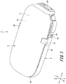
- Fig. 1 is a perspective view showing a drug solution administration apparatus
- Fig. 2 is a perspective view showing a state before a pump main body is mounted on a cradle device in the drug solution administration apparatus.
- An apparatus shown in Fig. 1 is a portable insulin pump for continuous drug solution administration into the body of a patient, such as a patch type, tube type, or even other portable drug solution administration apparatuses.
- the drug solution administration apparatus 1 is affixed to a living body to be used.
- the drug solution administration apparatus 1 includes a pump main body 2, a cradle device 3 on which the pump main body 2 is attachably and detachably mounted, and a connection port 6 mounted on the cradle device 3.
- the pump main body 2 and the cradle device 3 are assembled by a repeatedly detachable and attachable engagement structure section. As the engagement structure section, various structures can be applied as appropriate.
- the configuration of the pump main body 2 is described with reference to Figs. 1 to 5 .
- Fig. 3 is a perspective view of the pump main body 2
- Fig. 4 is a plan view showing the inner configuration of the pump main body 2.
- Fig. 5 is a partial cross-sectional view showing a state where the pump main body 2 is mounted on the cradle device 3.
- the pump main body 2 includes a housing 11 and a connecting needle tube 12.
- the housing 11 accommodates a liquid delivery pipe 13, a drug solution storage section 14, a driving section 15, a power supply section 16 that supplies power to the driving section 15, and a plunger mechanism 17 and a transmission mechanism 18 which are actuators.
- the drug solution storage section 14 is filled with the drug solution to be administered.
- the drug solution storage section 14 is connected to the liquid delivery pipe 13 .
- the plunger mechanism 17 that pushes out the drug solution is mounted.
- the transmission mechanism 18 is connected to the plunger mechanism 17.
- the transmission mechanism 18 is connected to the driving section 15, and transmits the driving force of the driving section 15 to the plunger mechanism 17 via gears, and the like. As the driving force is transmitted, the plunger mechanism 17 is driven. In this manner, by driving the plunger mechanism 17 and the transmission mechanism 18 which are actuators, the drug solution filled in the drug solution storage section 14 is delivered toward the liquid delivery pipe 13.
- the liquid delivery pipe 13 is a pipe disposed between the drug solution storage section 14 and the connecting needle tube 12. One end portion of the liquid delivery pipe 13 is connected to the drug solution storage section 14 .
- the liquid delivery pipe 13 is supported by a positioning section 39 that protrudes from the bottom surface portion 22 of the housing 11, which will be described later.
- One end portion of the liquid delivery pipe 13 and the other end portion on the opposite side are connected to the connecting needle tube 12 and used as a flow path of the drug solution.
- the drug solution that has passed through the liquid delivery pipe 13 is discharged from the connecting needle tube 12 .
- the liquid delivery pipe 13 is provided with at least one bent portion formed by bending an appropriate pipe member. In the present embodiment, the liquid delivery pipe 13 has three bent portions.
- the connecting needle tube 12 is punctured into a cap 82 provided in a connection section 81a of the connection port 6, which will be described later, when the pump main body 2 is mounted on the cradle device 3. Accordingly, the liquid delivery pipe 13 and the connection port 6 are fluid-connected to each other via the connecting needle tube 12.
- Stainless steel is applied as the liquid delivery pipe 13 and the connecting needle tube 12, for example, the austenitic stainless steel prescribed in ISO9626, or the material prescribed in JIS G 4305 cold-rolled stainless steel sheet and strip.
- SUS304 is preferable.
- a direction (mounting direction) in which the pump main body 2 is mounted on the cradle device 3 is a first direction X.
- the direction orthogonal to the first direction X and orthogonal to the direction in which the pump main body 2 and the cradle device 3 overlap each other is a second direction Y (width direction).
- the second direction Y is substantially parallel to the living body surface when the drug solution administration apparatus 1 administers the drug solution.
- the direction in which the pump main body 2 and the cradle device 3 overlap each other, that is, the direction orthogonal to both the first direction X and the second direction Y is a third direction Z (up-down direction) .
- the third direction Z is a direction that is orthogonal to the living body surface when the drug solution administration apparatus 1 administers the drug solution.
- the housing 11 is formed in a flat and substantially rectangular parallelepiped shape with curved corner portions.
- the housing 11 has the upper surface portion 21, a bottom surface portion 22, a front surface portion 23, a back surface portion 24, a first side surface portion 25, a second side surface portion 26, and a bottom surface accommodation section 27.
- the upper surface portion 21 and the bottom surface portion 22 are facing each other.
- the upper surface portion 21 is one surface positioned opposite to the side (bottom surface portion 22) where the upper surface portion 21 is mounted on the cradle device 3, in the pump main body 2.
- the upper surface portion 21 is formed in a substantially rectangular shape with curved corner portions, in the upper view.
- the upper surface portion 21 has the center portion bulging out in the third direction Z toward the opposite side of the bottom surface portion 22.
- the front surface portion 23 substantially perpendicularly communicates with a second end portion of the upper surface portion 21 in the first direction X
- the back surface portion 24 substantially perpendicularly communicates with a first end portion of the upper surface portion 21 in the first direction X.
- the front surface portion 23 and the back surface portion 24 are facing each other.
- the first side surface portion 25 substantially perpendicularly communicates with one end portion of the upper surface portion 21 in the second direction Y
- the second side surface portion 26 substantially perpendicularly communicates with the other end portion of the upper surface portion 21 in the second direction Y.
- an engagement projection 31 is formed in the front surface portion 23.
- the engagement projection 31 is formed on the other end portion side of the front surface portion 23 in the second direction Y.
- the engagement projection 31 protrudes from the front surface portion 23 toward the second end portion in the first direction X.
- the engagement projection 31 is engaged with an engagement hole 54 provided in the cradle device 3 described below.
- the bottom surface accommodation section 27 is formed in the corner portion of the bottom surface portion 22, the first side surface portion 25, and the front surface portion 23 in the housing 11.
- the bottom surface accommodation section 27 is a space which is recessed with a predetermined length (thickness) and a predetermined area (width) from the bottom surface portion 22 to the upper surface portion 21 along the third direction Z.
- a tubular connection opening 28 is formed on a wall surface 27a on the first end portion side in the first direction X in the bottom surface accommodation section 27.
- the connection opening 28 has a tube hole 28a that protrudes from the wall surface 27a toward the second end portion side in the first direction X (that is, in the mounting direction) .
- the connecting needle tube 12 is disposed in the tube hole 28a of the connection opening 28.
- the tube hole 28a protects the connecting needle tube 12 by protruding from the wall surface 27a to surround the connecting needle tube 12.
- the connecting needle tube 12 protrudes from the wall surface 27a in the tube hole 28a toward the second end portion side in the first direction X (in the mounting direction) .
- the direction in which the connection opening 28 protrudes from the wall surface 27a is parallel to the first direction X.
- connection port 6 attached to the cradle device 3 is accommodated in the bottom surface accommodation section 27. Furthermore, the connection section 81a and the cap 82 of the connection port 6 are inserted into the tube hole 28a of the connection opening 28.
- the connecting needle tube 12 protrudes from the wall surface 27a in the tube hole 28a toward the second end portion side in the first direction X (that is, in the mounting direction) . In other words, the direction in which the connecting needle tube 12 protrudes from the wall surface 27a is parallel to the first direction X.
- a needle support section 29 is formed on the inside of the housing 11 at the connection opening 28.
- the needle support section 29 supports the connecting needle tube 12.
- a concave portion 29a is formed in the needle support section 29.
- the needle support section 29 supports the connecting needle tube 12 from the second direction Y and the third direction Z.
- the concave portion 29a is filled with an adhesive P1 (refer to Fig. 5 ) for fixing the connecting needle tube 12. Accordingly, the connecting needle tube 12 can be reliably fixed to the needle support section 29. Accordingly, it is possible to prevent the positional deviation of the connecting needle tube 12 caused by the operation of connecting the pump main body 2 to the cradle device 3.
- the bottom surface portion 22 has a sliding groove portion 32 and a detection groove portion 34.
- the sliding groove portion 32 and the detection groove portion 34 are concave portions recessed from the bottom surface portion 22 toward the upper surface portion 21 along the third direction Z.
- the sliding groove portion 32 is formed in the middle of the second direction Y in the bottom surface portion 22.
- the sliding groove portion 32 is formed continuously from the second end portion to the first end portion in the first direction X in the bottom surface portion 22.
- the detection groove portion 34 is formed on one end portion side in the second direction Y in the bottom surface portion 22.
- the detection groove portion 34 extends from the wall surface 27a of the bottom surface accommodation section 27 across the first end portion in the first direction X.
- a mounting detection switch 33 is provided in the detection groove portion 34.
- the mounting detection switch 33 is pressed by a detection rail 52 provided in the cradle device 3, which will be described later, when the pump main body 2 is mounted on the cradle device 3. Then, when the mounting detection switch 33 is pressed, the mounting information to the control unit, which is not shown, is output. Accordingly, the control unit detects that the pump main body 2 has been mounted on the cradle device 3.
- the positioning section 39 is provided inside the bottom surface portion 22.
- the positioning section 39 is a projection that protrudes substantially perpendicularly from the inner surface in the bottom surface portion 22.
- the positioning section 39 is disposed in the vicinity of the needle support section 29.
- the positioning section 39 supports the liquid delivery pipe 13 and positions the liquid delivery pipe 13.
- the pump main body 2 and the cradle device 3 have a repeatedly detachable and attachable engagement structure section.
- the engagement structure section for example, has a hook mechanism.
- the first side surface portion 25 has the first guide groove portion 35 and the first engagement hook portion 36 as the engagement structure section.
- the first engagement hook portion 36 is formed at the first end portion of the first side surface portion 25 in the first direction X.
- the first engagement hook portion 36 is formed on the first end portion side of the first guide groove portion 35 in the first direction X.
- the first engagement hook portion 36 is attachably and detachably engaged with a first engagement receiving section 61 (refer to Fig. 2 ) of the cradle device 3, which will be described later.
- the first guide groove portion 35 is formed in the middle of the third direction Z in the first side surface portion 25.
- the first guide groove portion 35 is a groove portion recessed from the first side surface portion 25 into the housing 11 along the second direction Y.
- the first guide groove portion 35 extends toward the second end portion side along the first direction X from the vicinity of the first engagement hook portion 36 in the first side surface portion 25.
- Fig. 6 is a plan view showing the positional relationship of the connecting needle tube 12 and the first guide groove portion 35.
- an extension section 35a is provided at the second end portion of the first side surface portion 25, that is, on the bottom surface accommodation section 27 side.
- the extension section 35a is a plate-like portion that protrudes from the wall surface 27a of the bottom surface accommodation section 27 toward the second end portion in the first direction X at the second end portion of the first side surface portion 25.
- the extension section 35a protrudes toward the second end portion in the first direction X by a length h1 from the connection opening 28 that protrudes from the wall surface 27a.
- a protrusion length of the extension section 35a from the wall surface 27a is longer than a protrusion length of the connection opening 28 from the wall surface 27a.
- the length of the guide groove portion 35 extending from the wall surface of the housing 11 is longer than the length from the wall surface of the housing 11 to the opening surface of the connection opening 28.
- the length at which the guide groove portion 35 protrudes from the wall surface of housing 11 is longer than the length at which the connecting needle tube 12 protrudes from the wall surface of the housing 11. More specifically, the extension section 35a extends toward the second end portion side in the first direction X from the distal end of the connecting needle tube 12. Note that the extension section 35a may be formed flush with the first side surface portion 25. Note that it is preferable that the second end portion of the first side surface portion 25 is recessed into the housing 11 along the second direction Y with respect to the surface of the first side surface portion 25. More preferably, the extension section 35a is formed with the same surface as the bottom surface of the recess of the first guide groove portion 35.
- the first guide groove portion 35 is formed from the vicinity of the first engagement hook portion 36 across the extension section 35a. Therefore, the second end portion of the first guide groove portion 35 in the first direction X is disposed on the second end portion side in the first direction X from the distal end of the connecting needle tube 12 and the connection port 6.
- the second side surface portion 26 has a second guide groove portion 37 and a second engagement hook portion 38 as the engagement structure section.
- the second engagement hook portion 38 is formed at the first end portion of the first direction X in the second side surface portion 26.
- the second engagement hook portion 38 is attachably and detachably engaged with a second engagement receiving section 62 of the cradle device 3, which will be described later.
- the plurality of engagement structure sections (the first engagement hook portion 36 and the first engagement receiving section 61, the second engagement hook portion 38 and the second engagement receiving section 62) are symmetrically disposed with respect to a central axis of the first direction X in the pump main body 2 and the cradle device 3.
- the second guide groove portion 37 is formed in the middle of the third direction Z in the second side surface portion 26.
- the second guide groove portion 37 is a groove portion recessed from the second side surface portion 26 into the housing 11 along the second direction Y.
- the second guide groove portion 37 extends from the vicinity of the second engagement hook portion 38 along the first direction X with a length that is substantially the same as the length in the first direction X in the first guide groove portion 35.
- cradle device 3 will be described with reference to Figs. 1 , 2 , and 7 .
- Fig. 7 shows a perspective view in which the cradle device 3 and the connection port 6 are enlarged and showed.
- the cradle device 3 is configured to be capable of carrying the pump main body 2 having the above-described configuration.
- the cradle device 3 has a substantially flat plate-shaped placement surface portion 41, a first side wall portion 42, a second side wall portion 43, and a third side wall portion 44.
- the placement surface portion 41 is formed in a substantially rectangular shape with curved corner portions, in the upper view.
- the detection rail 52 On one surface of the placement surface portion 41, the detection rail 52, a sliding rail 53, and a mounting section 55 are provided.
- the mounting section 55 is formed at the second end portion of the placement surface portion 41 in the first direction X and is formed at one end portion in the second direction Y.
- the connection port 6 is mounted on the mounting section 55. Furthermore, in the mounting section 55, an insertion hole (not shown) through which a cannula 83 of the connection port 6 (will be described later) is inserted is provided.
- the detection rail 52 is formed at one end portion of the placement surface portion 41 in the second direction Y, that is, on the first end portion side of the mounting section 55 in the first direction X.
- the detection rail 52 is a projection portion that protrudes from one surface of the placement surface portion 41.
- the first end portion of the detection rail 52 has a gradual increase in thickness from the placement surface portion 41 as moving toward the second end portion side in the first direction X.
- the detection rail 52 extends for a predetermined length along the first direction X.
- the sliding rail 53 is formed in the middle of the second direction Y on one surface of the placement surface portion 41.
- the sliding rail 53 extends from the second end portion in the first direction X on one surface of the placement surface portion 41 toward the first end portion.
- the first side wall portion 42 is continuous substantially perpendicularly to the placement surface portion 41.
- the second side wall portion 43 is continuous substantially perpendicularly to the placement surface portion 41.
- the third side wall portion 44 is continuous substantially perpendicularly to the placement surface portion 41.
- the first side wall portion 42 and the second side wall portion 43 face each other. Three of the four sides of the placement surface portion 41 is connected to the first side wall portion 42, the second side wall portion 43 and the third side wall portion 44.
- the first end of the placement surface portion 41 in the first direction X does not have a side wall portion that is continuous and substantially perpendicular to the placement surface portion 41. In other words, the first end of the placement surface portion 41 in the first direction X and the first end portion are open. Accordingly, the pump main body 2 is inserted into the placement surface portion 41 from the first end side in the first direction X.
- the first side wall portion 42 faces the first side surface portion 25 of the housing 11 in the pump main body 2, and the second side wall portion 43 faces the second side surface portion 26.
- the third side wall portion 44 faces the front surface portion 23 of the housing 11.
- the engagement hole 54 is open.
- the engagement hole 54 is engaged with the engagement projection 31 of the pump main body 2.
- first guide rail 51 In the first side wall portion 42, a first guide rail 51, a first posture correction section 56, and the first engagement receiving section 61 are formed.
- the first engagement receiving section 61 is formed at the first end portion of the first side wall portion 42 in the first direction X.
- the first engagement receiving section 61 is an opening portion with the first side wall portion 42 cut out in a substantially rectangular shape.
- the first guide rail 51 protrudes from one surface facing the second side wall portion 43 in the first side wall portion 42 toward the other end portion in the second direction Y.
- the first guide rail 51 is a projection portion formed parallel to the first direction X from the second end portion of the first side wall portion 42 in the first direction X.
- the first guide rail 51 may not necessarily the projection portion which continuously extends.
- a notch 58 may be provided in the middle of the guide rail 51 as appropriate.
- the first guide rail 51 is formed by a first end portion side first guide rail 51a and a second end portion side first guide rail 51b.
- the second end portion of the first guide rail 51 in the first direction X extends to the position of the connection port 6 (which will be described later) attached to the mounting section 55.
- the first end portion of the first guide rail 51 in the first direction X is positioned on the first end portion side in the first direction X from the connection section 81a and the cap 82 of the connection port 6, which will be described later.
- the pump main body 2 When the pump main body 2 is mounted on the cradle device 3, the first guide rail 51 is engaged with the first guide groove portion 35 provided on the first side surface portion 25 of the pump main body 2. Accordingly, the pump main body 2 is guided in the mounting direction.
- the first posture correction section 56 is a plate-like protruding portion extending from the first side wall portion 42.
- the first posture correction section 56 extends further upward in the third direction Z from the first side wall portion 42.
- the first posture correction section 56 is formed on the first end portion side of the first guide rail 51 in the first direction X, in the first side wall portion 42.
- the first posture correction section 56 protrudes in the third direction Z from one end portion of the first side wall portion 42 in the third direction Z and is curved toward the other end portion in the second direction Y.
- the first posture correction section 56 is formed in a shape corresponding to the shape of the connection section (corner portion) between the upper surface portion 21 and the first side surface portion 25 in the housing 11.
- the distal end and/or the distal portion of the first posture correction section 56 is positioned above the placement surface portion 41 in the third direction Z in a side view from the first direction X of the cradle device 3.
- the second side wall portion 43 has a second guide rail (not shown), a second posture correction section 57, and the second engagement receiving section 62.
- the second engagement receiving section 62 is formed at the first end portion of the second side wall portion 43 in the first direction X.
- the second engagement receiving section 62 is an opening portion with the second side wall portion 43 cut out in a substantially rectangular shape.
- the second guide rail protrudes from one surface facing the first side wall portion 42 in the second side wall portion 43 toward one end portion in the second direction Y.
- the second guide rail is a projection portion formed parallel to the direction toward the first end from the second end portion of the second side wall portion 43 in the first direction X.
- the second posture correction section 57 is a plate-like protruding portion extending from the second side wall portion 43.
- the second posture correction section 57 extends further upward in the third direction Z from the second side wall portion 43.
- the second posture correction section 57 is formed on the first end portion side of the second guide rail in the first direction X, in the second side wall portion 43.
- the second posture correction section 57 is formed at a position facing the first posture correction section 56 formed in the first side wall portion 42.
- the second posture correction section 57 protrudes in the third direction Z from one end portion of the second side wall portion 43 in the third direction Z and is curved toward one end portion in the second direction Y.
- the second posture correction section 57 is formed in a shape corresponding to the shape of the corner portion between the upper surface portion 21 and the second side surface portion 26 in the housing 11.
- the distal end and/or the distal portion of the second posture correction section 57 is positioned above the placement surface portion 41 in the third direction Z in a side view from the first direction X of the cradle device 3.
- an affixing sheet that is affixed to the skin of the patient is provided.
- the affixing sheet is attached to the other surface opposite to one surface of the placement surface portion 41 of the cradle device 3.
- the affixing sheet has an opening portion (not shown) through which the cannula 83 of the connection port 6 (which will be described below) penetrates.
- the affixing sheet is made of a flexible member, and an adhesive layer affixed to the skin of the patient is formed on the surface opposite to the placement surface portion 41. In a state before being affixed to the skin of the patient, the adhesive layer of the affixing sheet is covered with a separation paper.
- connection port 6 will be described with reference to Figs. 5 and 7 .
- the connection port 6 has a port main body 81 and the cannula 83.
- the cannula 83 is held in the port main body 81.
- the port main body 81 has the tubular connection section 81a.
- the inside of the connection section 81a (tube hole 81b), the port main body 81, and the cannula 83 communicate with each other.
- the cap 82 is mounted on the distal portion of the connection section 81a, and the other end portion of the connection section 81a is connected to the port main body 81.
- the cap 82 seals the distal end opening of the connection section 81a. Accordingly, the inside of the connection port 6 is isolated from the external environment.
- the cannula 83 penetrates the placement surface portion 41 together with a puncture needle along the third direction Z and protrudes to the other surface (a surface affixed to the skin) of the placement surface portion 41.
- the cannula 83 is then punctured into the living body together with the puncture needle. After this, by removing the puncture needle, the cannula 83 is indwelt in the living body.
- connection section 81a of the port main body 81 faces the first end portion side of the first direction X, that is, the upstream side of the mounting direction.
- the connecting needle tube 12 of the pump main body 2 enters the tube hole 81b by puncturing the septum surface of the cap 82.
- the port main body 81 is connected to the liquid delivery pipe 13 of the pump main body 2, and the liquid delivery pipe 13 is fluid-connected to the cannula 83.
- the drug solution stored in the drug solution storage section 14 of the pump main body 2 is delivered to the connection port 6 via the liquid delivery pipe 13 and administered to the patient through the cannula 83, by driving the driving section 15.
- Figs. 8 to 10 are views showing a state where the pump main body 2 is mounted on the cradle device 3.
- the separation paper of the affixing sheet in the cradle device 3 is peeled off, and the affixing sheet is affixed to the skin of the patient. Accordingly, the cradle device 3 is attached to the skin of the patient via the affixing sheet. Then, as shown in Fig. 2 , the connection port 6 is mounted on the mounting section 55 of the cradle device 3, and the cannula 83 is punctured and indwelt in the patient by using a puncture apparatus (not shown) . After the puncture, the puncture apparatus is removed from the cradle device 3 and disposed of.
- the pump main body 2 is inserted from the first end portion side of the cradle device 3 in the first direction X. Then, the pump main body 2 is made slide along the placement surface portion 41 of the cradle device 3 toward the second end in the first direction X. At this time, the posture of the pump main body 2 at the start of mounting is corrected by attaching the first posture correction section 56 and the second posture correction section 57.
- a state where the first guide rail 51 is inserted into the first guide groove portion 35 formed in the extension section 35a is maintained. Accordingly, before the pump main body 2 is connected to the cradle device 3, the tilt in the mounting direction of the pump main body 2 on the cradle device 3 is corrected. As a result, the cap 82 and/or the connection section 81a can be inserted straight into the connection opening 28 along the first direction X.
- the notch 58 for engaging the puncture apparatus (not shown) is provided in the middle of the first guide rail 51. Accordingly, the second end portion side first guide rail 51b and the first end portion side first guide rail 51a are formed across the notch 58 as the first guide rail 51. The second end portion of the extension section 35a goes over the notch 58 before the cap 82 is inserted into the tube hole 82a. More specifically, before the cap 82 is inserted into the tube hole 28a, the first guide groove portion 35 is inserted into the second end portion side first guide rail 51b.
- the distal end of the connecting needle tube 12 is attached to the cap 82 of the connection port 6.
- the first guide groove portion 35 in the pump main body 2 and the first guide rail 51 of the cradle device 3 are maintained to be engaged. Therefore, the pump main body 2 is guided by the first guide groove portion 35 and the first guide rail 51 to be mounted in the correct direction.
- the cap 82 can be inserted into the connection opening 28 and the connecting needle tube 12 can be attached to the septum surface of the cap 82 substantially perpendicularly. Furthermore, the distal end of the connecting needle tube 12 can puncture the septum surface of the cap 82 and keep the puncture direction substantially constant while passing therethrough.
- the cap 82 and the connection section 81a of the connection port 6 are inserted into the tube hole 28a of the connection opening 28.
- the connection opening 28 holds the cap 82 and the connection section 81a in the tube hole 28a. Accordingly, even when stress is applied to the cradle device 3, it is possible to prevent the cap 82 or the connection section 81a from being deformed.
- the connecting needle tube 12 of the pump main body 2 is punctured into the cap 82 of the connection port 6, and the connection port 6 and the liquid delivery pipe 13 communicate with each other. Accordingly, the drug solution storage section 14 of the pump main body 2 and the cannula 83 of the connection port 6 are connected to each other via the liquid delivery pipe 13, the connecting needle tube 12 and the port main body 81.
- the engagement projection 31 is engaged with the engagement hole 54 of the cradle device 3. Then, the first engagement hook portion 36 is engaged with the first engagement receiving section 61, and the second engagement hook portion 38 is engaged with the second engagement receiving section 62. Accordingly, the pump main body 2 mounted on the cradle device 3 can be prevented from falling out of the cradle device 3.
- the detection rail 52 of the cradle device 3 slides through the detection groove portion 34 of the pump main body 2 and presses the mounting detection switch 33. Accordingly, the control unit (not shown) provided in the pump main body 2 detects that the pump main body 2 has been mounted on the cradle device 3. As a result, the mounting operation of the pump main body 2 onto the cradle device 3 is completed.
- the mounting direction of the pump main body 2 onto the cradle device 3 is guided in the correct direction. Therefore, it is possible to prevent the mounting detection switch 33 from being pressed by the detection rail 52 in an inappropriate mounting state where the pump main body 2 is tilted against the cradle device 3, and to prevent false detection from occurring. As a result, the mounting state of the pump main body 2 to the cradle device 3 is normally detected by the mounting detection switch 33.
- a length t1 at which the first guide rail 51 and the first guide groove portion 35 are engaged with each other is set to be longer than a length t2 at which the connecting needle tube 12 enters the connection port 6 (t1 > t2) . Therefore, the strength around the connection port 6 in the cradle device 3 can be increased by the engagement of the first guide rail 51 and the first guide groove portion 35.
- the puncture guide function can be enhanced in the vicinity of the connecting needle tube 12 and the cap 82 during the puncture operation from before the connecting needle tube 12 is punctured into the cap 82.
- extension section 35a By providing the extension section 35a to one end portion of the first guide groove portion 35, even when the drug solution administration apparatus 1 is in use, it is possible to enhance posture holding force of the connection opening 28, the connection section 81a, and the connecting needle tube 12 around the connection port 6 in the cradle device 3.
- a difference occurs in the followability to the living body surface between the cradle device 3 and the pump main body 2.
- the connecting needle tube 12 widens the cap 82 and the drug solution leaks out.
- the first guide rail 51 and the first guide groove portion 35 can correct the posture of the connection port 6 and the connecting needle tube 12 of the cradle device 3 so as to be parallel to the first direction X.
- extension section 35a it is possible to correctly hold the positions of the connection opening 28 and the connecting needle tube 12 in a state of being punctured in the cap 82, and thus, it is possible to prevent the connecting needle tube 12 from widening the puncture portion in the septum surface of the cap 82, or the connecting needle tube 12 or the connection port 6 from deforming. Accordingly, a gap is generated between the connecting needle tube 12 and the cap 82, the drug solution is prevented from leaking out.
- a guide groove portion may be provided on the cradle device 3 side, and a guide rail which is engaged with the guide groove portion may be provided on the pump main body 2 side.
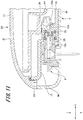
- Fig. 11 is a cross-sectional view showing the drug solution administration apparatus according to the second embodiment. Parts common to the drug solution administration apparatus 1 according to the first embodiment will be given the same reference numerals, and the duplicated description thereof will be omitted.
- a pump main body 2A of the drug solution administration apparatus has a liquid delivery needle tube 12A in which the connecting needle tube and the liquid delivery pipe are integrally formed.
- the drug solution storage section 14 and the connection port 6 are connected to each other via a liquid delivery needle tube 12A, which has a needle section at one end portion.
- the liquid delivery needle tube 12A has at least one bent portion.
- One end portion of the liquid delivery needle tube 12A is connected to the drug solution storage section 14 (refer to Fig. 4 ).
- the liquid delivery needle tube 12A is supported by the positioning section 39 for positioning.
- the other end portion of the liquid delivery needle tube 12A is supported by the needle support section 29, and the distal portion protrudes outward from the connection opening 28. Then, the other end portion of the liquid delivery needle tube 12A is fixed to the needle support section 29 by the adhesive P1 filled in the concave portion 29a of the needle support section 29. At the distal end of the liquid delivery needle tube 12A, a needle tip 12b that can puncture the cap 82 is formed. Accordingly, the connecting needle tube 12A can be reliably fixed to the needle support section 29. Accordingly, it is possible to prevent the positional deviation of the connecting needle tube 12A caused by the operation of puncturing the pump main body 2 to the cradle device 3. Since fixtures such as needle hub members can be omitted, weight reduction can be achieved.
- Stainless steel is applied as the liquid delivery needle tube 12A, for example, the austenitic stainless steel prescribed in IS09626, or the material prescribed in JIS G 4305 cold-rolled stainless steel sheet and strip.
- SUS304 is preferable.
- the other configurations are the same as those of the drug solution administration apparatus 1 according to the first embodiment, and thus, the description thereof will be omitted.
- the drug solution administration apparatus having the liquid delivery needle tube 12A illustrated in Fig. 11 can also have the same effect as that of the drug solution administration apparatus 1 according to the above-described first embodiment.
- the number of components can be reduced compared to the drug solution administration apparatus 1 according to the first embodiment by integrally forming the connecting needle tube and the liquid delivery pipe. It is possible to reduce the weight of the drug solution administration apparatus.
- an insulin pump that administers insulin is applied as a drug solution administration apparatus
- Various other drug solutions such as analgesics, anti-cancer drugs, HIV drugs, iron chelators, pulmonary hypertension drugs, and the like, may be used as drug solution to be administered.
- drug solution administration apparatuses that are affixed to the skin of the patient
- the present invention can also be applied to other apparatuses that are used in combination with cradle devices that can be attached to the clothing or belongings of the patient.
- body fluid component measurement apparatuses used for monitoring blood glucose levels, and the like, and patient information collection devices that collect information such as heart rate or number of steps are exemplified, and it is needless to say that these apparatuses can be utilized in a multifaceted manner in the member communication function.
Landscapes
- Health & Medical Sciences (AREA)
- Heart & Thoracic Surgery (AREA)
- Vascular Medicine (AREA)
- Engineering & Computer Science (AREA)
- Anesthesiology (AREA)
- Biomedical Technology (AREA)
- Hematology (AREA)
- Life Sciences & Earth Sciences (AREA)
- Animal Behavior & Ethology (AREA)
- General Health & Medical Sciences (AREA)
- Public Health (AREA)
- Veterinary Medicine (AREA)
- Dermatology (AREA)
- Infusion, Injection, And Reservoir Apparatuses (AREA)
Abstract
Description
- The present invention relates to a drug solution administration apparatus, for example, a drug solution administration apparatus for performing continuous drug solution administration such as an insulin pump.
- In recent years, treatments in which drug solution is continuously administered into the body of a patient is performed by subcutaneous injection or intravenous injection. For example, as a treatment for diabetic patients, a continuous injection of a trace amount of insulin into the body of a patient has been implemented. In this treatment, a portable drug solution administration apparatus (so-called insulin pump) that can be fixed to the body or clothing of a patient and carried around is used to administer the drug solution (insulin) to the patient throughout the day.
- In such a portable drug solution administration apparatus, the cradle device is first affixed to the skin of a patient. Next, a connection port is mounted on the cradle device, and a cannula provided in the connection port is punctured and indwelt in the patient. The pump main body, which stores and delivers the drug solution, is mounted on the cradle device. At this time, the connecting needle tube that delivers the drug solution from the pump main body is connected to the connection port (for example, refer to PTL 1) .
- PTL 1:
JP-T-2007-509661 - However, in the technology described in PTL 1, in a case where the cradle device was deformed, there is a concern that the connecting needle tube of the pump main body is punctured diagonally against a plug body provided in the connection port, and the connecting needle tube and the connection port are connected to each other in an incorrect state. Furthermore, even when the connecting needle tube is correctly punctured into the connection port, in a case where the cradle device is bent, there is a concern that the plug body is widened by the connecting needle tube, a gap is generated between the connecting needle tube and the plug body, and the drug solution leaks out through this gap.
- In consideration of the above-described problem, the object is to provide a drug solution administration apparatus that can puncture the connecting needle tube provided in the pump main body to a correct position of the connection port.
- In order to solve the above-described problem and achieve the object, the drug solution administration apparatus includes a pump main body, a cradle device, and a connection port. The pump main body has a drug solution storage section, a liquid delivery pipe connected to the drug solution storage section, and a housing that accommodates the drug solution storage section and the liquid delivery pipe. The cradle device that has a placement surface portion on which the pump main body is placed, and the pump main body being attachably and detachably mounted on the cradle device from a first end toward a second end in a first direction. The connection port has a port main body connected to the liquid delivery pipe and a cannula insertable into a living body, and is mounted on the placement surface portion. The pump main body has a connecting needle tube connected to the liquid delivery pipe and punctured into the connection port. The connection port is mounted on a second end portion of the cradle device in the first direction, and a connection section where the connecting needle tube is punctured is oriented toward the first end in the first direction. One of the housing and the cradle device is provided with a projecting guide rail formed parallel to the first direction. The remaining other one of the housing and the cradle device is provided with a guide groove portion that is slidably engaged with the guide rail. The second end in the first direction in the guide rail or the guide groove portion which is formed in the housing is positioned on a second end side in the first direction from a distal end of the connecting needle tube.
- Another drug solution administration apparatus includes a pump main body, a cradle device, and a connection port. The pump main body has a drug solution storage section, a liquid delivery pipe connected to the drug solution storage section, a housing that accommodates the drug solution storage section and the liquid delivery pipe, and a connection opening. The cradle device has a placement surface portion on which the pump main body is placed, and the pump main body being attachably and detachably mounted on the cradle device from a first end toward a second end in a first direction. The connection port has a port main body connected to the pump main body and a cannula insertable into a living body, and is mounted on the placement surface portion. A bottom surface accommodation section that accommodates the connection port is formed in a bottom surface portion of the housing placed in the placement surface portion. The connection opening protrudes in the first direction from a wall surface formed on a first end side of the bottom surface accommodation section. One of the housing and the cradle device is provided with a guide rail formed parallel to the first direction. The remaining other one of the housing and the cradle device is provided with a guide groove portion that is slidably engaged with the guide rail. A second end in the first direction in the guide rail or the guide groove portion which is formed in the housing is positioned on a second end side in the first direction from a distal end of the connection opening.
- According to the drug solution administration apparatus having the above-described configuration, the connecting needle tube provided in the pump main body can be punctured at the correct position of the connection port.
-
- [
Fig. 1] Fig. 1 is a perspective view showing a drug solution administration apparatus according to a first embodiment. - [
Fig. 2] Fig. 2 is a perspective view showing a state before a pump main body is mounted on a cradle device in the drug solution administration apparatus according to the first embodiment. - [
Fig. 3] Fig. 3 is a perspective view showing the pump main body of the drug solution administration apparatus according to the first embodiment. - [
Fig. 4] Fig. 4 is a plan view showing an inner configuration of the pump main body of the drug solution administration apparatus according to the first embodiment. - [
Fig. 5] Fig. 5 is a cross-sectional view showing a connection state of a connecting needle tube and a connection port of the drug solution administration apparatus according to the first embodiment. - [
Fig. 6] Fig. 6 is a plan view showing a positional relationship of the connecting needle tube and a guide groove portion in the pump main body of the drug solution administration apparatus according to the first embodiment. - [
Fig. 7] Fig. 7 is a perspective view showing the cradle device and the connection port in the drug solution administration apparatus according to the first embodiment. - [
Fig. 8] Fig. 8 is a view showing a state where the pump main body is mounted on the cradle device in the drug solution administration apparatus according to the first embodiment,Fig. 8A is a side view showing a start of engagement of the guide groove portion and a guide rail, andFig. 8B is a cross-sectional view. - [
Fig. 9] Fig. 9 is a view showing a state where the pump main body is mounted on the cradle device in the drug solution administration apparatus according to the first embodiment,Fig. 9A is a side view showing a state where the connecting needle tube is attached to a cap, andFig. 9B is a cross-sectional view. - [
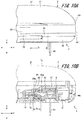
Fig. 10] Fig. 10 is a view showing a state where the pump main body is mounted on the cradle device in the drug solution administration apparatus according to the first embodiment,Fig. 10A is a side view showing a state where the connecting needle tube is punctured to the cap, andFig. 10B is a cross-sectional view. - [
Fig. 11] Fig. 11 is a cross-sectional view showing a drug solution administration apparatus according to a second embodiment. - Hereinafter, embodiments of a drug solution administration apparatus will be described with reference to
Figs. 1 to 11 . Note that the common members in each drawing will be given the same reference numerals. The present invention is not limited to the following aspects. - First, a configuration example of the drug solution administration apparatus according to a first embodiment (hereinafter referred to as "this example") will be described with reference to
Figs. 1 to 5 . -
Fig. 1 is a perspective view showing a drug solution administration apparatus, andFig. 2 is a perspective view showing a state before a pump main body is mounted on a cradle device in the drug solution administration apparatus. - An apparatus shown in
Fig. 1 is a portable insulin pump for continuous drug solution administration into the body of a patient, such as a patch type, tube type, or even other portable drug solution administration apparatuses. The drug solution administration apparatus 1 is affixed to a living body to be used. The drug solution administration apparatus 1 includes a pumpmain body 2, acradle device 3 on which the pumpmain body 2 is attachably and detachably mounted, and aconnection port 6 mounted on thecradle device 3. The pumpmain body 2 and thecradle device 3 are assembled by a repeatedly detachable and attachable engagement structure section. As the engagement structure section, various structures can be applied as appropriate. - The configuration of the pump
main body 2 is described with reference toFigs. 1 to 5 . -
Fig. 3 is a perspective view of the pumpmain body 2, andFig. 4 is a plan view showing the inner configuration of the pumpmain body 2.Fig. 5 is a partial cross-sectional view showing a state where the pumpmain body 2 is mounted on thecradle device 3. - As shown in
Figs. 1 to 3 , the pumpmain body 2 includes ahousing 11 and a connectingneedle tube 12. As shown inFig. 4 , thehousing 11 accommodates aliquid delivery pipe 13, a drugsolution storage section 14, a drivingsection 15, apower supply section 16 that supplies power to the drivingsection 15, and aplunger mechanism 17 and atransmission mechanism 18 which are actuators. The drugsolution storage section 14 is filled with the drug solution to be administered. The drugsolution storage section 14 is connected to theliquid delivery pipe 13 . On the drugsolution storage section 14, theplunger mechanism 17 that pushes out the drug solution is mounted. - The
transmission mechanism 18 is connected to theplunger mechanism 17. Thetransmission mechanism 18 is connected to the drivingsection 15, and transmits the driving force of the drivingsection 15 to theplunger mechanism 17 via gears, and the like. As the driving force is transmitted, theplunger mechanism 17 is driven. In this manner, by driving theplunger mechanism 17 and thetransmission mechanism 18 which are actuators, the drug solution filled in the drugsolution storage section 14 is delivered toward theliquid delivery pipe 13. - The
liquid delivery pipe 13 is a pipe disposed between the drugsolution storage section 14 and the connectingneedle tube 12. One end portion of theliquid delivery pipe 13 is connected to the drugsolution storage section 14 . Theliquid delivery pipe 13 is supported by apositioning section 39 that protrudes from thebottom surface portion 22 of thehousing 11, which will be described later. One end portion of theliquid delivery pipe 13 and the other end portion on the opposite side are connected to the connectingneedle tube 12 and used as a flow path of the drug solution. The drug solution that has passed through theliquid delivery pipe 13 is discharged from the connectingneedle tube 12 . Note that theliquid delivery pipe 13 is provided with at least one bent portion formed by bending an appropriate pipe member. In the present embodiment, theliquid delivery pipe 13 has three bent portions. - As shown in
Figs. 4 and5 , the connectingneedle tube 12 is punctured into acap 82 provided in aconnection section 81a of theconnection port 6, which will be described later, when the pumpmain body 2 is mounted on thecradle device 3. Accordingly, theliquid delivery pipe 13 and theconnection port 6 are fluid-connected to each other via the connectingneedle tube 12. - Stainless steel is applied as the
liquid delivery pipe 13 and the connectingneedle tube 12, for example, the austenitic stainless steel prescribed in ISO9626, or the material prescribed in JIS G 4305 cold-rolled stainless steel sheet and strip. In the present embodiment, SUS304 is preferable. - Hereafter, by sliding the pump
main body 2 in the direction from the first end to the second end of thecradle device 3, a direction (mounting direction) in which the pumpmain body 2 is mounted on thecradle device 3 is a first direction X. The direction orthogonal to the first direction X and orthogonal to the direction in which the pumpmain body 2 and thecradle device 3 overlap each other is a second direction Y (width direction). The second direction Y is substantially parallel to the living body surface when the drug solution administration apparatus 1 administers the drug solution. The direction in which the pumpmain body 2 and thecradle device 3 overlap each other, that is, the direction orthogonal to both the first direction X and the second direction Y is a third direction Z (up-down direction) . Here, the third direction Z is a direction that is orthogonal to the living body surface when the drug solution administration apparatus 1 administers the drug solution. - As shown in
Figs. 2 and3 , thehousing 11 is formed in a flat and substantially rectangular parallelepiped shape with curved corner portions. Thehousing 11 has theupper surface portion 21, abottom surface portion 22, afront surface portion 23, aback surface portion 24, a firstside surface portion 25, a secondside surface portion 26, and a bottomsurface accommodation section 27. Theupper surface portion 21 and thebottom surface portion 22 are facing each other. Theupper surface portion 21 is one surface positioned opposite to the side (bottom surface portion 22) where theupper surface portion 21 is mounted on thecradle device 3, in the pumpmain body 2. Theupper surface portion 21 is formed in a substantially rectangular shape with curved corner portions, in the upper view. Theupper surface portion 21 has the center portion bulging out in the third direction Z toward the opposite side of thebottom surface portion 22. - The
front surface portion 23 substantially perpendicularly communicates with a second end portion of theupper surface portion 21 in the first direction X, and theback surface portion 24 substantially perpendicularly communicates with a first end portion of theupper surface portion 21 in the first direction X. Thefront surface portion 23 and theback surface portion 24 are facing each other. Furthermore, the firstside surface portion 25 substantially perpendicularly communicates with one end portion of theupper surface portion 21 in the second direction Y, and the secondside surface portion 26 substantially perpendicularly communicates with the other end portion of theupper surface portion 21 in the second direction Y. - As shown in
Fig. 3 , anengagement projection 31 is formed in thefront surface portion 23. In a case where thefront surface portion 23 is viewed from the second end in the first direction X toward the first end, theengagement projection 31 is formed on the other end portion side of thefront surface portion 23 in the second direction Y. Theengagement projection 31 protrudes from thefront surface portion 23 toward the second end portion in the first direction X. Theengagement projection 31 is engaged with anengagement hole 54 provided in thecradle device 3 described below. - The bottom
surface accommodation section 27 is formed in the corner portion of thebottom surface portion 22, the firstside surface portion 25, and thefront surface portion 23 in thehousing 11. The bottomsurface accommodation section 27 is a space which is recessed with a predetermined length (thickness) and a predetermined area (width) from thebottom surface portion 22 to theupper surface portion 21 along the third direction Z. - A
tubular connection opening 28 is formed on awall surface 27a on the first end portion side in the first direction X in the bottomsurface accommodation section 27. Theconnection opening 28 has atube hole 28a that protrudes from thewall surface 27a toward the second end portion side in the first direction X (that is, in the mounting direction) . The connectingneedle tube 12 is disposed in thetube hole 28a of theconnection opening 28. Thetube hole 28a protects the connectingneedle tube 12 by protruding from thewall surface 27a to surround the connectingneedle tube 12. The connectingneedle tube 12 protrudes from thewall surface 27a in thetube hole 28a toward the second end portion side in the first direction X (in the mounting direction) . In other words, the direction in which theconnection opening 28 protrudes from thewall surface 27a is parallel to the first direction X. - As shown in
Figs. 4 and5 , when the pumpmain body 2 is mounted on thecradle device 3, theconnection port 6 attached to thecradle device 3 is accommodated in the bottomsurface accommodation section 27. Furthermore, theconnection section 81a and thecap 82 of theconnection port 6 are inserted into thetube hole 28a of theconnection opening 28. The connectingneedle tube 12 protrudes from thewall surface 27a in thetube hole 28a toward the second end portion side in the first direction X (that is, in the mounting direction) . In other words, the direction in which the connectingneedle tube 12 protrudes from thewall surface 27a is parallel to the first direction X. - A
needle support section 29 is formed on the inside of thehousing 11 at theconnection opening 28. Theneedle support section 29 supports the connectingneedle tube 12. Aconcave portion 29a is formed in theneedle support section 29. Theneedle support section 29 supports the connectingneedle tube 12 from the second direction Y and the third direction Z. Theconcave portion 29a is filled with an adhesive P1 (refer toFig. 5 ) for fixing the connectingneedle tube 12. Accordingly, the connectingneedle tube 12 can be reliably fixed to theneedle support section 29. Accordingly, it is possible to prevent the positional deviation of the connectingneedle tube 12 caused by the operation of connecting the pumpmain body 2 to thecradle device 3. - As shown in
Fig. 3 , thebottom surface portion 22 has a slidinggroove portion 32 and adetection groove portion 34. The slidinggroove portion 32 and thedetection groove portion 34 are concave portions recessed from thebottom surface portion 22 toward theupper surface portion 21 along the third direction Z. The slidinggroove portion 32 is formed in the middle of the second direction Y in thebottom surface portion 22. The slidinggroove portion 32 is formed continuously from the second end portion to the first end portion in the first direction X in thebottom surface portion 22. - The
detection groove portion 34 is formed on one end portion side in the second direction Y in thebottom surface portion 22. Thedetection groove portion 34 extends from thewall surface 27a of the bottomsurface accommodation section 27 across the first end portion in the first direction X. In thedetection groove portion 34, a mountingdetection switch 33 is provided. - The mounting
detection switch 33 is pressed by adetection rail 52 provided in thecradle device 3, which will be described later, when the pumpmain body 2 is mounted on thecradle device 3. Then, when the mountingdetection switch 33 is pressed, the mounting information to the control unit, which is not shown, is output. Accordingly, the control unit detects that the pumpmain body 2 has been mounted on thecradle device 3. - As shown in
Fig. 4 , thepositioning section 39 is provided inside thebottom surface portion 22. Thepositioning section 39 is a projection that protrudes substantially perpendicularly from the inner surface in thebottom surface portion 22. Thepositioning section 39 is disposed in the vicinity of theneedle support section 29. Thepositioning section 39 supports theliquid delivery pipe 13 and positions theliquid delivery pipe 13. - As shown in
Fig. 3 , in the present embodiment, the pumpmain body 2 and thecradle device 3 have a repeatedly detachable and attachable engagement structure section. The engagement structure section, for example, has a hook mechanism. Specifically, the firstside surface portion 25 has the firstguide groove portion 35 and the firstengagement hook portion 36 as the engagement structure section. The firstengagement hook portion 36 is formed at the first end portion of the firstside surface portion 25 in the first direction X. The firstengagement hook portion 36 is formed on the first end portion side of the firstguide groove portion 35 in the first direction X. The firstengagement hook portion 36 is attachably and detachably engaged with a first engagement receiving section 61 (refer toFig. 2 ) of thecradle device 3, which will be described later. - The first
guide groove portion 35 is formed in the middle of the third direction Z in the firstside surface portion 25. The firstguide groove portion 35 is a groove portion recessed from the firstside surface portion 25 into thehousing 11 along the second direction Y. The firstguide groove portion 35 extends toward the second end portion side along the first direction X from the vicinity of the firstengagement hook portion 36 in the firstside surface portion 25. -
Fig. 6 is a plan view showing the positional relationship of the connectingneedle tube 12 and the firstguide groove portion 35. - As shown in
Figs. 3 to 6 , anextension section 35a is provided at the second end portion of the firstside surface portion 25, that is, on the bottomsurface accommodation section 27 side. As shown inFig. 6 , theextension section 35a is a plate-like portion that protrudes from thewall surface 27a of the bottomsurface accommodation section 27 toward the second end portion in the first direction X at the second end portion of the firstside surface portion 25. Theextension section 35a protrudes toward the second end portion in the first direction X by a length h1 from theconnection opening 28 that protrudes from thewall surface 27a. In other words, a protrusion length of theextension section 35a from thewall surface 27a is longer than a protrusion length of the connection opening 28 from thewall surface 27a. The length of theguide groove portion 35 extending from the wall surface of thehousing 11 is longer than the length from the wall surface of thehousing 11 to the opening surface of theconnection opening 28. - The length at which the
guide groove portion 35 protrudes from the wall surface ofhousing 11 is longer than the length at which the connectingneedle tube 12 protrudes from the wall surface of thehousing 11. More specifically, theextension section 35a extends toward the second end portion side in the first direction X from the distal end of the connectingneedle tube 12. Note that theextension section 35a may be formed flush with the firstside surface portion 25. Note that it is preferable that the second end portion of the firstside surface portion 25 is recessed into thehousing 11 along the second direction Y with respect to the surface of the firstside surface portion 25. More preferably, theextension section 35a is formed with the same surface as the bottom surface of the recess of the firstguide groove portion 35. Accordingly, it is possible to not only prevent sinkage during molding, but also maintain the posture of the connectingneedle tube 12 such that the connectingneedle tube 12 can be correctly punctured into thecap 82 immediately before and throughout the puncture by positioning the connectingneedle tube 12 and thecap 82 closer to each other, as described below. - The first
guide groove portion 35 is formed from the vicinity of the firstengagement hook portion 36 across theextension section 35a. Therefore, the second end portion of the firstguide groove portion 35 in the first direction X is disposed on the second end portion side in the first direction X from the distal end of the connectingneedle tube 12 and theconnection port 6. By providing the firstengagement hook portion 36 and the firstengagement receiving section 61 on the first end portion side in the first direction X in the pumpmain body 2 and thecradle device 3, the length at which the firstguide groove portion 35 guides the pumpmain body 2 can be ensured when attaching and detaching the pumpmain body 2 to and from thecradle device 3. Accordingly, the guiding function of the firstguide groove portion 35 can be strengthened. - It is preferable that a plurality of engagement structure sections are provided. In addition to the first
side surface portion 25, it is preferable to provide an engagement structure section on the facing secondside surface portion 26. As shown inFig. 2 , the secondside surface portion 26 has a secondguide groove portion 37 and a secondengagement hook portion 38 as the engagement structure section. The secondengagement hook portion 38 is formed at the first end portion of the first direction X in the secondside surface portion 26. The secondengagement hook portion 38 is attachably and detachably engaged with a secondengagement receiving section 62 of thecradle device 3, which will be described later. The plurality of engagement structure sections (the firstengagement hook portion 36 and the firstengagement receiving section 61, the secondengagement hook portion 38 and the second engagement receiving section 62) are symmetrically disposed with respect to a central axis of the first direction X in the pumpmain body 2 and thecradle device 3. - The second
guide groove portion 37 is formed in the middle of the third direction Z in the secondside surface portion 26. The secondguide groove portion 37 is a groove portion recessed from the secondside surface portion 26 into thehousing 11 along the second direction Y. The secondguide groove portion 37 extends from the vicinity of the secondengagement hook portion 38 along the first direction X with a length that is substantially the same as the length in the first direction X in the firstguide groove portion 35. By providing the secondengagement hook portion 38 and the secondengagement receiving section 62 on the first end portion side in the first direction X in the pumpmain body 2 and thecradle device 3, the length at which the secondguide groove portion 36 guides the pumpmain body 2 can be ensured when attaching and detaching the pumpmain body 2 to and from thecradle device 3. Accordingly, the guiding function of the secondguide groove portion 36 can be strengthened. - Next, the
cradle device 3 will be described with reference toFigs. 1 ,2 , and7 . -
Fig. 7 shows a perspective view in which thecradle device 3 and theconnection port 6 are enlarged and showed. - As shown in
Fig. 1 , thecradle device 3 is configured to be capable of carrying the pumpmain body 2 having the above-described configuration. As shown inFig. 2 , thecradle device 3 has a substantially flat plate-shapedplacement surface portion 41, a firstside wall portion 42, a secondside wall portion 43, and a thirdside wall portion 44. Theplacement surface portion 41 is formed in a substantially rectangular shape with curved corner portions, in the upper view. When the pumpmain body 2 is mounted on thecradle device 3, thebottom surface portion 22 of thehousing 11 of the pumpmain body 2 is placed on theplacement surface portion 41. - On one surface of the
placement surface portion 41, thedetection rail 52, a slidingrail 53, and a mountingsection 55 are provided. The mountingsection 55 is formed at the second end portion of theplacement surface portion 41 in the first direction X and is formed at one end portion in the second direction Y. As shown inFig. 6 , theconnection port 6 is mounted on the mountingsection 55. Furthermore, in the mountingsection 55, an insertion hole (not shown) through which acannula 83 of the connection port 6 (will be described later) is inserted is provided. - The
detection rail 52 is formed at one end portion of theplacement surface portion 41 in the second direction Y, that is, on the first end portion side of the mountingsection 55 in the first direction X. Thedetection rail 52 is a projection portion that protrudes from one surface of theplacement surface portion 41. The first end portion of thedetection rail 52 has a gradual increase in thickness from theplacement surface portion 41 as moving toward the second end portion side in the first direction X. Thedetection rail 52 extends for a predetermined length along the first direction X. When the pumpmain body 2 is mounted on thecradle device 3, thedetection rail 52 enters thedetection groove portion 34 provided on the pumpmain body 2. Thedetection rail 52 then presses the mountingdetection switch 33. - The sliding
rail 53 is formed in the middle of the second direction Y on one surface of theplacement surface portion 41. The slidingrail 53 extends from the second end portion in the first direction X on one surface of theplacement surface portion 41 toward the first end portion. When the pumpmain body 2 is mounted on thecradle device 3, the slidingrail 53 is slidably fitted with the slidinggroove portion 32 provided in thebottom surface portion 22 of the pumpmain body 2. - At one end portion of the
placement surface portion 41 in the second direction Y, the firstside wall portion 42 is continuous substantially perpendicularly to theplacement surface portion 41. At the other end portion of theplacement surface portion 41 in the second direction Y, the secondside wall portion 43 is continuous substantially perpendicularly to theplacement surface portion 41. At the second end portion of theplacement surface portion 41 in the first direction X, the thirdside wall portion 44 is continuous substantially perpendicularly to theplacement surface portion 41. The firstside wall portion 42 and the secondside wall portion 43 face each other. Three of the four sides of theplacement surface portion 41 is connected to the firstside wall portion 42, the secondside wall portion 43 and the thirdside wall portion 44. The first end of theplacement surface portion 41 in the first direction X does not have a side wall portion that is continuous and substantially perpendicular to theplacement surface portion 41. In other words, the first end of theplacement surface portion 41 in the first direction X and the first end portion are open. Accordingly, the pumpmain body 2 is inserted into theplacement surface portion 41 from the first end side in the first direction X. - In a state where the pump
main body 2 is mounted on thecradle device 3, the firstside wall portion 42 faces the firstside surface portion 25 of thehousing 11 in the pumpmain body 2, and the secondside wall portion 43 faces the secondside surface portion 26. The thirdside wall portion 44 faces thefront surface portion 23 of thehousing 11. - As shown in
Fig. 2 , in the thirdside wall portion 44, theengagement hole 54 is open. When the pumpmain body 2 is mounted on thecradle device 3, theengagement hole 54 is engaged with theengagement projection 31 of the pumpmain body 2. - In the first
side wall portion 42, afirst guide rail 51, a firstposture correction section 56, and the firstengagement receiving section 61 are formed. The firstengagement receiving section 61 is formed at the first end portion of the firstside wall portion 42 in the first direction X. The firstengagement receiving section 61 is an opening portion with the firstside wall portion 42 cut out in a substantially rectangular shape. When the pumpmain body 2 is mounted on thecradle device 3, the firstengagement hook portion 36 is attachably and detachably engaged with the firstengagement receiving section 61. - As shown in
Fig. 7 , thefirst guide rail 51 protrudes from one surface facing the secondside wall portion 43 in the firstside wall portion 42 toward the other end portion in the second direction Y. Thefirst guide rail 51 is a projection portion formed parallel to the first direction X from the second end portion of the firstside wall portion 42 in the first direction X. Thefirst guide rail 51 may not necessarily the projection portion which continuously extends. As shown inFigs. 2 and7 , anotch 58 may be provided in the middle of theguide rail 51 as appropriate. In the present embodiment, thefirst guide rail 51 is formed by a first end portion sidefirst guide rail 51a and a second end portion sidefirst guide rail 51b. - The second end portion of the
first guide rail 51 in the first direction X extends to the position of the connection port 6 (which will be described later) attached to the mountingsection 55. The first end portion of thefirst guide rail 51 in the first direction X is positioned on the first end portion side in the first direction X from theconnection section 81a and thecap 82 of theconnection port 6, which will be described later. - When the pump
main body 2 is mounted on thecradle device 3, thefirst guide rail 51 is engaged with the firstguide groove portion 35 provided on the firstside surface portion 25 of the pumpmain body 2. Accordingly, the pumpmain body 2 is guided in the mounting direction. - As shown in
Figs. 1 and2 , the firstposture correction section 56 is a plate-like protruding portion extending from the firstside wall portion 42. The firstposture correction section 56 extends further upward in the third direction Z from the firstside wall portion 42. The firstposture correction section 56 is formed on the first end portion side of thefirst guide rail 51 in the first direction X, in the firstside wall portion 42. - The first
posture correction section 56 protrudes in the third direction Z from one end portion of the firstside wall portion 42 in the third direction Z and is curved toward the other end portion in the second direction Y. In other words, the firstposture correction section 56 is formed in a shape corresponding to the shape of the connection section (corner portion) between theupper surface portion 21 and the firstside surface portion 25 in thehousing 11. The distal end and/or the distal portion of the firstposture correction section 56 is positioned above theplacement surface portion 41 in the third direction Z in a side view from the first direction X of thecradle device 3. - As shown in
Figs. 1 and2 , the secondside wall portion 43 has a second guide rail (not shown), a secondposture correction section 57, and the secondengagement receiving section 62. The secondengagement receiving section 62 is formed at the first end portion of the secondside wall portion 43 in the first direction X. The secondengagement receiving section 62 is an opening portion with the secondside wall portion 43 cut out in a substantially rectangular shape. When the pumpmain body 2 is mounted on thecradle device 3, the secondengagement hook portion 38 is attachably and detachably engaged with the secondengagement receiving section 62. - The second guide rail protrudes from one surface facing the first
side wall portion 42 in the secondside wall portion 43 toward one end portion in the second direction Y. The second guide rail is a projection portion formed parallel to the direction toward the first end from the second end portion of the secondside wall portion 43 in the first direction X. When the pumpmain body 2 is mounted on thecradle device 3, the second guide rail is engaged with the secondguide groove portion 37 provided on the secondside surface portion 26 of the pumpmain body 2. Accordingly, the pumpmain body 2 is guided in the mounting direction. - The second
posture correction section 57 is a plate-like protruding portion extending from the secondside wall portion 43. The secondposture correction section 57 extends further upward in the third direction Z from the secondside wall portion 43. The secondposture correction section 57 is formed on the first end portion side of the second guide rail in the first direction X, in the secondside wall portion 43. The secondposture correction section 57 is formed at a position facing the firstposture correction section 56 formed in the firstside wall portion 42. - The second
posture correction section 57 protrudes in the third direction Z from one end portion of the secondside wall portion 43 in the third direction Z and is curved toward one end portion in the second direction Y. In other words, the secondposture correction section 57 is formed in a shape corresponding to the shape of the corner portion between theupper surface portion 21 and the secondside surface portion 26 in thehousing 11. The distal end and/or the distal portion of the secondposture correction section 57 is positioned above theplacement surface portion 41 in the third direction Z in a side view from the first direction X of thecradle device 3. When the pumpmain body 2 is mounted on thecradle device 3, the firstposture correction section 56 and the secondposture correction section 57 correct the posture of the pumpmain body 2 when the pumpmain body 2 is mounted. - In the
cradle device 3, an affixing sheet that is affixed to the skin of the patient is provided. The affixing sheet is attached to the other surface opposite to one surface of theplacement surface portion 41 of thecradle device 3. The affixing sheet has an opening portion (not shown) through which thecannula 83 of the connection port 6 (which will be described below) penetrates. - The affixing sheet is made of a flexible member, and an adhesive layer affixed to the skin of the patient is formed on the surface opposite to the
placement surface portion 41. In a state before being affixed to the skin of the patient, the adhesive layer of the affixing sheet is covered with a separation paper. - Next, the
connection port 6 will be described with reference toFigs. 5 and7 . - As shown in
Figs. 5 and7 , theconnection port 6 has a portmain body 81 and thecannula 83. Thecannula 83 is held in the portmain body 81. The portmain body 81 has thetubular connection section 81a. The inside of theconnection section 81a (tube hole 81b), the portmain body 81, and thecannula 83 communicate with each other. Thecap 82 is mounted on the distal portion of theconnection section 81a, and the other end portion of theconnection section 81a is connected to the portmain body 81. Thecap 82 seals the distal end opening of theconnection section 81a. Accordingly, the inside of theconnection port 6 is isolated from the external environment. - When the
connection port 6 is mounted on the mountingsection 55 of thecradle device 3, thecannula 83 penetrates theplacement surface portion 41 together with a puncture needle along the third direction Z and protrudes to the other surface (a surface affixed to the skin) of theplacement surface portion 41. Thecannula 83 is then punctured into the living body together with the puncture needle. After this, by removing the puncture needle, thecannula 83 is indwelt in the living body. - The
connection section 81a of the portmain body 81 faces the first end portion side of the first direction X, that is, the upstream side of the mounting direction. The connectingneedle tube 12 of the pumpmain body 2 enters thetube hole 81b by puncturing the septum surface of thecap 82. Accordingly, the portmain body 81 is connected to theliquid delivery pipe 13 of the pumpmain body 2, and theliquid delivery pipe 13 is fluid-connected to thecannula 83. The drug solution stored in the drugsolution storage section 14 of the pumpmain body 2 is delivered to theconnection port 6 via theliquid delivery pipe 13 and administered to the patient through thecannula 83, by driving thedriving section 15. - Next, an example of the mounting operation of mounting the pump
main body 2 on thecradle device 3 in the drug solution administration apparatus 1 having the above-described configuration will be described with reference toFigs. 1 ,2 , and8 to 10 . -
Figs. 8 to 10 are views showing a state where the pumpmain body 2 is mounted on thecradle device 3. - First, the separation paper of the affixing sheet in the
cradle device 3 is peeled off, and the affixing sheet is affixed to the skin of the patient. Accordingly, thecradle device 3 is attached to the skin of the patient via the affixing sheet. Then, as shown inFig. 2 , theconnection port 6 is mounted on the mountingsection 55 of thecradle device 3, and thecannula 83 is punctured and indwelt in the patient by using a puncture apparatus (not shown) . After the puncture, the puncture apparatus is removed from thecradle device 3 and disposed of. - Next, as shown in
Fig. 2 , the pumpmain body 2 is inserted from the first end portion side of thecradle device 3 in the first direction X. Then, the pumpmain body 2 is made slide along theplacement surface portion 41 of thecradle device 3 toward the second end in the first direction X. At this time, the posture of the pumpmain body 2 at the start of mounting is corrected by attaching the firstposture correction section 56 and the secondposture correction section 57. - As shown in
Figs. 8A and 8B , before thecap 82 of theconnection port 6 is inserted into thetube hole 28a of theconnection opening 28, a state where thefirst guide rail 51 is inserted into the firstguide groove portion 35 formed in theextension section 35a is maintained. Accordingly, before the pumpmain body 2 is connected to thecradle device 3, the tilt in the mounting direction of the pumpmain body 2 on thecradle device 3 is corrected. As a result, thecap 82 and/or theconnection section 81a can be inserted straight into theconnection opening 28 along the first direction X. - In this example, in the middle of the
first guide rail 51, in a state before puncturing thecannula 83, thenotch 58 for engaging the puncture apparatus (not shown) is provided. Accordingly, the second end portion sidefirst guide rail 51b and the first end portion sidefirst guide rail 51a are formed across thenotch 58 as thefirst guide rail 51. The second end portion of theextension section 35a goes over thenotch 58 before thecap 82 is inserted into the tube hole 82a. More specifically, before thecap 82 is inserted into thetube hole 28a, the firstguide groove portion 35 is inserted into the second end portion sidefirst guide rail 51b. - Next, when the pump
main body 2 is slid further toward the second end side in the first direction X against thecradle device 3, as shown inFigs. 9A and 9B , the distal end of the connectingneedle tube 12 is attached to thecap 82 of theconnection port 6. During this time, the firstguide groove portion 35 in the pumpmain body 2 and thefirst guide rail 51 of thecradle device 3 are maintained to be engaged. Therefore, the pumpmain body 2 is guided by the firstguide groove portion 35 and thefirst guide rail 51 to be mounted in the correct direction. By providing theextension section 35a in the correct direction, thecap 82 can be inserted into theconnection opening 28 and the connectingneedle tube 12 can be attached to the septum surface of thecap 82 substantially perpendicularly. Furthermore, the distal end of the connectingneedle tube 12 can puncture the septum surface of thecap 82 and keep the puncture direction substantially constant while passing therethrough. - By further sliding the pump
main body 2 to the second end in the first direction X, as shown inFigs. 10a and 10b , thecap 82 and theconnection section 81a of theconnection port 6 are inserted into thetube hole 28a of theconnection opening 28. Theconnection opening 28 holds thecap 82 and theconnection section 81a in thetube hole 28a. Accordingly, even when stress is applied to thecradle device 3, it is possible to prevent thecap 82 or theconnection section 81a from being deformed. - Then, the connecting
needle tube 12 of the pumpmain body 2 is punctured into thecap 82 of theconnection port 6, and theconnection port 6 and theliquid delivery pipe 13 communicate with each other. Accordingly, the drugsolution storage section 14 of the pumpmain body 2 and thecannula 83 of theconnection port 6 are connected to each other via theliquid delivery pipe 13, the connectingneedle tube 12 and the portmain body 81. - The
engagement projection 31 is engaged with theengagement hole 54 of thecradle device 3. Then, the firstengagement hook portion 36 is engaged with the firstengagement receiving section 61, and the secondengagement hook portion 38 is engaged with the secondengagement receiving section 62. Accordingly, the pumpmain body 2 mounted on thecradle device 3 can be prevented from falling out of thecradle device 3. - The
detection rail 52 of thecradle device 3 slides through thedetection groove portion 34 of the pumpmain body 2 and presses the mountingdetection switch 33. Accordingly, the control unit (not shown) provided in the pumpmain body 2 detects that the pumpmain body 2 has been mounted on thecradle device 3. As a result, the mounting operation of the pumpmain body 2 onto thecradle device 3 is completed. - According to the drug solution administration apparatus 1 of this example, as the
first guide rail 51 is engaged with the firstguide groove portion 35, the mounting direction of the pumpmain body 2 onto thecradle device 3 is guided in the correct direction. Therefore, it is possible to prevent the mountingdetection switch 33 from being pressed by thedetection rail 52 in an inappropriate mounting state where the pumpmain body 2 is tilted against thecradle device 3, and to prevent false detection from occurring. As a result, the mounting state of the pumpmain body 2 to thecradle device 3 is normally detected by the mountingdetection switch 33. - As shown in
Figs. 10A and 10B , a length t1 at which thefirst guide rail 51 and the firstguide groove portion 35 are engaged with each other is set to be longer than a length t2 at which the connectingneedle tube 12 enters the connection port 6 (t1 > t2) . Therefore, the strength around theconnection port 6 in thecradle device 3 can be increased by the engagement of thefirst guide rail 51 and the firstguide groove portion 35. - In other words, even in a case where stress is applied to the
cradle device 3 and thecradle device 3 is bent during the operation of attaching the pumpmain body 2 to thecradle device 3, the puncture guide function can be enhanced in the vicinity of the connectingneedle tube 12 and thecap 82 during the puncture operation from before the connectingneedle tube 12 is punctured into thecap 82. - By providing the
extension section 35a to one end portion of the firstguide groove portion 35, even when the drug solution administration apparatus 1 is in use, it is possible to enhance posture holding force of theconnection opening 28, theconnection section 81a, and the connectingneedle tube 12 around theconnection port 6 in thecradle device 3. Depending on the movement of the living body surface or the external force, there is a case where a difference occurs in the followability to the living body surface between thecradle device 3 and the pumpmain body 2. At this time, as a part of the pumpmain body 2 is separated from thecradle device 3, there is a concern that the connectingneedle tube 12 widens thecap 82 and the drug solution leaks out. In other words, even in a case where stress is applied to thecradle device 3 and deformation occurs in theplacement surface portion 41 and the like, thefirst guide rail 51 and the firstguide groove portion 35 can correct the posture of theconnection port 6 and the connectingneedle tube 12 of thecradle device 3 so as to be parallel to the first direction X. - Furthermore, by providing the
extension section 35a, it is possible to correctly hold the positions of theconnection opening 28 and the connectingneedle tube 12 in a state of being punctured in thecap 82, and thus, it is possible to prevent the connectingneedle tube 12 from widening the puncture portion in the septum surface of thecap 82, or the connectingneedle tube 12 or theconnection port 6 from deforming. Accordingly, a gap is generated between the connectingneedle tube 12 and thecap 82, the drug solution is prevented from leaking out. - Note that, in the above-described embodiment, an example was described in which the projecting
first guide rail 51 and the second guide rail are provided on thecradle device 3 side and the firstguide groove portion 35 and the secondguide groove portion 37 which are engaged with thefirst guide rail 51 and the second guide rail are provided on the pumpmain body 2 side, but the present invention is not limited thereto. For example, a guide groove portion may be provided on thecradle device 3 side, and a guide rail which is engaged with the guide groove portion may be provided on the pumpmain body 2 side. - Next, the drug solution administration apparatus according to a second embodiment will be described with reference to
Fig. 11 . -
Fig. 11 is a cross-sectional view showing the drug solution administration apparatus according to the second embodiment. Parts common to the drug solution administration apparatus 1 according to the first embodiment will be given the same reference numerals, and the duplicated description thereof will be omitted. - As shown in
Fig. 11 , a pumpmain body 2A of the drug solution administration apparatus according to the second embodiment has a liquiddelivery needle tube 12A in which the connecting needle tube and the liquid delivery pipe are integrally formed. In other words, the drugsolution storage section 14 and theconnection port 6 are connected to each other via a liquiddelivery needle tube 12A, which has a needle section at one end portion. Similar to the first embodiment, the liquiddelivery needle tube 12A has at least one bent portion. One end portion of the liquiddelivery needle tube 12A is connected to the drug solution storage section 14 (refer toFig. 4 ). The liquiddelivery needle tube 12A is supported by thepositioning section 39 for positioning. - The other end portion of the liquid
delivery needle tube 12A is supported by theneedle support section 29, and the distal portion protrudes outward from theconnection opening 28. Then, the other end portion of the liquiddelivery needle tube 12A is fixed to theneedle support section 29 by the adhesive P1 filled in theconcave portion 29a of theneedle support section 29. At the distal end of the liquiddelivery needle tube 12A, aneedle tip 12b that can puncture thecap 82 is formed. Accordingly, the connectingneedle tube 12A can be reliably fixed to theneedle support section 29. Accordingly, it is possible to prevent the positional deviation of the connectingneedle tube 12A caused by the operation of puncturing the pumpmain body 2 to thecradle device 3. Since fixtures such as needle hub members can be omitted, weight reduction can be achieved. - Stainless steel is applied as the liquid
delivery needle tube 12A, for example, the austenitic stainless steel prescribed in IS09626, or the material prescribed in JIS G 4305 cold-rolled stainless steel sheet and strip. In the present embodiment, SUS304 is preferable. - The other configurations are the same as those of the drug solution administration apparatus 1 according to the first embodiment, and thus, the description thereof will be omitted. The drug solution administration apparatus having the liquid
delivery needle tube 12A illustrated inFig. 11 can also have the same effect as that of the drug solution administration apparatus 1 according to the above-described first embodiment. - Note that, according to the drug solution administration apparatus of the second embodiment, the number of components can be reduced compared to the drug solution administration apparatus 1 according to the first embodiment by integrally forming the connecting needle tube and the liquid delivery pipe. It is possible to reduce the weight of the drug solution administration apparatus.
- Above, embodiments of the present invention, including the operation effects have been described. However, the drug solution administration apparatus of the present invention is not limited to the above-described embodiments, and various variations can be implemented within the scope not departing from the gist of the present invention described in the claims.
- In the above-described embodiments, an example has been described in which an insulin pump that administers insulin is applied as a drug solution administration apparatus, but the present invention is not limited thereto. Various other drug solutions, such as analgesics, anti-cancer drugs, HIV drugs, iron chelators, pulmonary hypertension drugs, and the like, may be used as drug solution to be administered. Not being limited to drug solution administration apparatuses that are affixed to the skin of the patient, the present invention can also be applied to other apparatuses that are used in combination with cradle devices that can be attached to the clothing or belongings of the patient. For example, body fluid component measurement apparatuses used for monitoring blood glucose levels, and the like, and patient information collection devices that collect information such as heart rate or number of steps, are exemplified, and it is needless to say that these apparatuses can be utilized in a multifaceted manner in the member communication function.
- Note that, in this specification, although words such as "parallel" and "orthogonal" were used, these do not mean only strict "parallel" and "orthogonal", but may also mean a state of being "substantially parallel" or "substantially orthogonal" including "parallel" and "orthogonal" and within the range of capable of performing the functions.
-
- 1
- DRUG SOLUTION ADMINISTRATION APPARATUS
- 2
- PUMP MAIN BODY
- 3 130 230
- CRADLE DEVICE
- 6
- CONNECTION PORT
- 11
- HOUSING
- 12
- CONNECTING NEEDLE TUBE
- 12A
- LIQUID DELIVERY NEEDLE TUBE
- 13
- LIQUID DELIVERY PIPE
- 14
- DRUG SOLUTION STORAGE SECTION
- 15
- DRIVING SECTION
- 16
- POWER SUPPLY SECTION
- 17
- PLUNGER MECHANISM
- 18
- TRANSMISSION MECHANISM
- 21
- UPPER SURFACE PORTION
- 22
- BOTTOM SURFACE PORTION
- 23
- FRONT SURFACE PORTION
- 24
- BACK SURFACE PORTION
- 25
- FIRST SIDE SURFACE PORTION
- 26
- SECOND SIDE SURFACE PORTION
- 27
- BOTTOM SURFACE ACCOMMODATION SECTION
- 27a
- WALL SURFACE
- 28
- CONNECTION OPENING
- 28a
- TUBE HOLE
- 31
- ENGAGEMENT PROJECTION
- 32
- SLIDING GROOVE PORTION
- 33
- MOUNTING DETECTION SWITCH
- 34
- DETECTION GROOVE PORTION
- 35
- FIRST GUIDE GROOVE PORTION
- 35a
- EXTENSION SECTION
- 36
- FIRST ENGAGEMENT HOOK PORTION
- 37
- SECOND GUIDE GROOVE PORTION
- 38
- SECOND ENGAGEMENT HOOK PORTION
- 41
- PLACEMENT SURFACE PORTION
- 42
- FIRST SIDE WALL PORTION
- 43
- SECOND SIDE WALL PORTION
- 44
- THIRD SIDE WALL PORTION
- 51
- FIRST GUIDE RAIL
- 52
- DETECTION RAIL
- 53
- SLIDING RAIL
- 54
- ENGAGEMENT HOLE
- 55
- MOUNTING SECTION
- 56 57 156 157 256
- POSTURE CORRECTION SECTION
- 81
- PORT MAIN BODY
- 81a
- CONNECTION SECTION
- 82
- CAP
- 82
- CANNULA
- 256b
- INSERTION OPENING
- X
- FIRST DIRECTION (MOUNTING DIRECTION)
- Y
- SECOND DIRECTION (WIDTH DIRECTION)
- Z
- THIRD DIRECTION (UP-DOWN DIRECTION)
Claims (14)
- A drug solution administration apparatus comprising:a pump main body having a drug solution storage section, a liquid delivery pipe connected to the drug solution storage section, and a housing that accommodates the drug solution storage section and the liquid delivery pipe;a cradle device that has a placement surface portion on which the pump main body is placed, and the pump main body being attachably and detachably mounted on the cradle device from a first end toward a second end in a first direction; anda connection port that has a port main body connected to the liquid delivery pipe and a cannula insertable into a living body, and is mounted on the placement surface portion, whereinthe pump main body has a connecting needle tube connected to the liquid delivery pipe and punctured into the connection port,the connection port is mounted on a second end portion of the cradle device in the first direction, and a connection section where the connecting needle tube is punctured is oriented toward the first end in the first direction,one of the housing and the cradle device is provided with a projecting guide rail formed parallel to the first direction,the remaining other one of the housing and the cradle device is provided with a guide groove portion that is slidably engaged with the guide rail, anda second end in the first direction in the guide rail or the guide groove portion which is formed in the housing is positioned on a second end side in the first direction from a distal end of the connecting needle tube.
- The drug solution administration apparatus according to claim 1, wherein
the second end in the first direction in the guide rail or the guide groove portion which is formed in the cradle device is positioned on the second end side in the first direction from the connection section of the connection port mounted on the cradle device. - The drug solution administration apparatus according to claim 1 or 2, wherein
a length at which the guide rail and the guide groove portion are engaged with each other is set to be longer than a length at which the connecting needle tube is punctured into the connection section. - The drug solution administration apparatus according to any one of claims 1 to 3, whereinthe housing includesa bottom surface portion placed on the placement surface portion, anda side surface portion that rises from one end portion of the bottom surface portion in a second direction orthogonal to the first direction, in a third direction orthogonal to the first direction and the second direction,the cradle device has a side wall portion that rises from one end portion in the second direction in the placement surface portion in the third direction, and faces the side surface portion,the guide rail is formed in one of the side surface portion and the side wall portion, andthe guide groove portion is formed in the remaining other one of the side surface portion and the side wall portion.
- The drug solution administration apparatus according to claim 4, whereina bottom surface accommodation section that accommodates the connection port is formed in the bottom surface portion of the housing, andthe connecting needle tube protrudes in the first direction from a wall surface formed on a first end side of the bottom surface accommodation section.
- The drug solution administration apparatus according to claim 5, whereinthe bottom surface accommodation section is formed at a second end portion in the first direction in the bottom surface portion and the side surface portion,the side surface portion has an extension section that protrudes from the wall surface of the bottom surface accommodation section toward the second end in the first direction, anda second end portion in the first direction of the guide rail or the guide groove portion is formed in the extension section.
- The drug solution administration apparatus according to claim 6, wherein
a protrusion length of the extension section from the wall surface is longer than a length at which the connecting needle tube protrudes from the wall surface. - The drug solution administration apparatus according to any one of claims 5 to 7, whereina tubular connection opening that protrudes in the first direction is formed on the wall surface of the bottom surface accommodation section,the connecting needle tube is disposed in a tube hole of the connection opening, andthe connection section of the connection port is inserted into the tube hole of the connection opening.
- The drug solution administration apparatus according to any one of claims 1 to 8, wherein
the connecting needle tube is formed integrally with the liquid delivery pipe. - A drug solution administration apparatus comprising:a pump main body having a drug solution storage section, a liquid delivery pipe connected to the drug solution storage section, a housing that accommodates the drug solution storage section and the liquid delivery pipe, and a connection opening;a cradle device that has a placement surface portion on which the pump main body is placed, and the pump main body being attachably and detachably mounted on the cradle device from a first end toward a second end in a first direction; anda connection port that has a port main body connected to the pump main body and a cannula insertable into a living body, and is mounted on the placement surface portion, whereina bottom surface accommodation section that accommodates the connection port is formed in a bottom surface portion of the housing placed in the placement surface portion,the connection opening protrudes in the first direction from a wall surface formed on a first end side of the bottom surface accommodation section,one of the housing and the cradle device is provided with a guide rail formed parallel to the first direction,the remaining other one of the housing and the cradle device is provided with a guide groove portion that is slidably engaged with the guide rail, anda second end in the first direction in the guide rail or the guide groove portion which is formed in the housing is positioned on a second end side in the first direction from a distal end of the connection opening.
- The drug solution administration apparatus according to claim 10, wherein
the connection port is mounted on a second end portion of the cradle device in the first direction. - The drug solution administration apparatus according to claim 10 or 11, wherein
the connection opening further includes a connecting needle tube. - The drug solution administration apparatus according to claim 12, wherein
the connecting needle tube is formed integrally with the liquid delivery pipe. - The drug solution administration apparatus according to any one of claims 1 to 13, whereinthe housing and the cradle device are connected to each other attachably and detachably via a plurality of engagement structure sections, andthe engagement structure sections are formed on a first end portion side in the first direction in the pump main body and the cradle device.
Applications Claiming Priority (2)
| Application Number | Priority Date | Filing Date | Title |
|---|---|---|---|
| JP2019045414 | 2019-03-13 | ||
| PCT/JP2020/007327 WO2020184160A1 (en) | 2019-03-13 | 2020-02-25 | Liquid medicine administration apparatus |
Publications (3)
| Publication Number | Publication Date |
|---|---|
| EP3925643A1 true EP3925643A1 (en) | 2021-12-22 |
| EP3925643A4 EP3925643A4 (en) | 2022-04-20 |
| EP3925643B1 EP3925643B1 (en) | 2024-11-27 |
Family
ID=72426757
Family Applications (1)
| Application Number | Title | Priority Date | Filing Date |
|---|---|---|---|
| EP20770787.8A Active EP3925643B1 (en) | 2019-03-13 | 2020-02-25 | Liquid medicine administration apparatus |
Country Status (4)
| Country | Link |
|---|---|
| EP (1) | EP3925643B1 (en) |
| JP (1) | JP7361758B2 (en) |
| CN (1) | CN113164678B (en) |
| WO (1) | WO2020184160A1 (en) |
Cited By (3)
| Publication number | Priority date | Publication date | Assignee | Title |
|---|---|---|---|---|
| USD1007676S1 (en) | 2021-11-16 | 2023-12-12 | Regeneron Pharmaceuticals, Inc. | Wearable autoinjector |
| US12226613B2 (en) | 2017-05-05 | 2025-02-18 | Regeneron Pharmaceuticals, Inc. | Auto-injector and related methods of use |
| US12533298B2 (en) | 2015-03-10 | 2026-01-27 | Regeneron Pharmaceuticals, Inc. | Aseptic piercing system and method |
Families Citing this family (5)
| Publication number | Priority date | Publication date | Assignee | Title |
|---|---|---|---|---|
| US11642454B2 (en) | 2019-06-06 | 2023-05-09 | Medtronic Minimed, Inc. | Fluid infusion systems |
| JP7717151B2 (en) * | 2021-03-25 | 2025-08-01 | テルモ株式会社 | Medical solution administration device |
| JPWO2022202278A1 (en) * | 2021-03-25 | 2022-09-29 | ||
| US11419976B1 (en) | 2021-04-30 | 2022-08-23 | Fresenius Kabi Deutschland Gmbh | Wearable drug delivery device with pressurized fluid dispensing |
| CN120078988A (en) * | 2025-03-04 | 2025-06-03 | 江西奇仁生物科技有限责任公司 | A portable intelligent electric injection pen |
Family Cites Families (8)
| Publication number | Priority date | Publication date | Assignee | Title |
|---|---|---|---|---|
| WO2006089958A1 (en) * | 2005-02-25 | 2006-08-31 | Novo Nordisk A/S | Pump assembly with safety valve |
| CN101426542A (en) | 2006-04-26 | 2009-05-06 | 诺沃-诺迪斯克有限公司 | Skin-mountable device in packaging comprising coated seal member |
| US8945068B2 (en) * | 2011-02-22 | 2015-02-03 | Medtronic Minimed, Inc. | Fluid reservoir having a fluid delivery needle for a fluid infusion device |
| EP2902056B1 (en) * | 2012-09-28 | 2022-04-27 | Terumo Kabushiki Kaisha | Puncture device and medical fluid application device |
| JPWO2016075976A1 (en) * | 2014-11-11 | 2017-08-17 | テルモ株式会社 | Chemical solution administration device |
| JP6647062B2 (en) * | 2016-02-04 | 2020-02-14 | テルモ株式会社 | Protective member and drug solution administration device |
| JP6710056B2 (en) * | 2016-02-04 | 2020-06-17 | テルモ株式会社 | Chemical dosing device |
| EP3524295B1 (en) * | 2016-10-05 | 2021-06-16 | Terumo Kabushiki Kaisha | Liquid medicine administration device and control method for liquid medicine administration device |
-
2020
- 2020-02-25 JP JP2021504895A patent/JP7361758B2/en active Active
- 2020-02-25 CN CN202080006864.8A patent/CN113164678B/en active Active
- 2020-02-25 EP EP20770787.8A patent/EP3925643B1/en active Active
- 2020-02-25 WO PCT/JP2020/007327 patent/WO2020184160A1/en not_active Ceased
Cited By (4)
| Publication number | Priority date | Publication date | Assignee | Title |
|---|---|---|---|---|
| US12533298B2 (en) | 2015-03-10 | 2026-01-27 | Regeneron Pharmaceuticals, Inc. | Aseptic piercing system and method |
| US12226613B2 (en) | 2017-05-05 | 2025-02-18 | Regeneron Pharmaceuticals, Inc. | Auto-injector and related methods of use |
| USD1007676S1 (en) | 2021-11-16 | 2023-12-12 | Regeneron Pharmaceuticals, Inc. | Wearable autoinjector |
| USD1122440S1 (en) | 2021-11-16 | 2026-04-14 | Regeneron Pharmaceuticals, Inc. | Wearable autoinjector |
Also Published As
| Publication number | Publication date |
|---|---|
| CN113164678A (en) | 2021-07-23 |
| WO2020184160A1 (en) | 2020-09-17 |
| JPWO2020184160A1 (en) | 2020-09-17 |
| EP3925643A4 (en) | 2022-04-20 |
| EP3925643B1 (en) | 2024-11-27 |
| CN113164678B (en) | 2023-02-17 |
| JP7361758B2 (en) | 2023-10-16 |
Similar Documents
| Publication | Publication Date | Title |
|---|---|---|
| EP3925643B1 (en) | Liquid medicine administration apparatus | |
| US20240050652A1 (en) | Infusion pump and system for preventing mischanneling of multiplle medicaments | |
| EP1824536B1 (en) | Ventilated skin mountable device | |
| CN205019519U (en) | Angled inserter for drug infusion | |
| RU2468828C2 (en) | Cannula and introduction device | |
| US9522223B2 (en) | Systems for fluid reservoir retention | |
| ES2975710T3 (en) | Device for sustained delivery of a therapeutic liquid | |
| EP4364766A2 (en) | Apparatus for pumping fluid | |
| EP3769801A1 (en) | Infusion device system and apparatus | |
| JP2009539444A (en) | An assembly comprising a device attachable to the skin and a package of the device | |
| US20230060176A1 (en) | Injection Assembly Apparatuses, Systems, and Methods | |
| CN102548598A (en) | Delivery device with sensor and one or more cannulas | |
| CN104619365A (en) | Puncture device and medical fluid application device | |
| EP3679970B1 (en) | Cradle for an infusion pump unit | |
| EP3915611A1 (en) | Medical fluid administration apparatus and cradle device | |
| EP4302799B1 (en) | Pharmaceutical liquid administration device | |
| JP6979837B2 (en) | Drug administration device | |
| JP6959813B2 (en) | Chemical administration device | |
| EP4548946A1 (en) | Cannula port, cradle device and drug solution administration device | |
| JP2024050282A (en) | Cannula report, cradle device and drug solution administration device |
Legal Events
| Date | Code | Title | Description |
|---|---|---|---|
| STAA | Information on the status of an ep patent application or granted ep patent |
Free format text: STATUS: THE INTERNATIONAL PUBLICATION HAS BEEN MADE |
|
| PUAI | Public reference made under article 153(3) epc to a published international application that has entered the european phase |
Free format text: ORIGINAL CODE: 0009012 |
|
| STAA | Information on the status of an ep patent application or granted ep patent |
Free format text: STATUS: REQUEST FOR EXAMINATION WAS MADE |
|
| 17P | Request for examination filed |
Effective date: 20210914 |
|
| AK | Designated contracting states |
Kind code of ref document: A1 Designated state(s): AL AT BE BG CH CY CZ DE DK EE ES FI FR GB GR HR HU IE IS IT LI LT LU LV MC MK MT NL NO PL PT RO RS SE SI SK SM TR |
|
| A4 | Supplementary search report drawn up and despatched |
Effective date: 20220317 |
|
| RIC1 | Information provided on ipc code assigned before grant |
Ipc: A61M 5/162 20060101ALN20220311BHEP Ipc: A61M 5/14 20060101ALI20220311BHEP Ipc: A61M 5/158 20060101ALI20220311BHEP Ipc: A61M 5/142 20060101AFI20220311BHEP |
|
| DAV | Request for validation of the european patent (deleted) | ||
| DAX | Request for extension of the european patent (deleted) | ||
| RIC1 | Information provided on ipc code assigned before grant |
Ipc: A61M 5/162 20060101ALN20240523BHEP Ipc: A61M 5/14 20060101ALI20240523BHEP Ipc: A61M 5/158 20060101ALI20240523BHEP Ipc: A61M 5/142 20060101AFI20240523BHEP |
|
| GRAP | Despatch of communication of intention to grant a patent |
Free format text: ORIGINAL CODE: EPIDOSNIGR1 |
|
| STAA | Information on the status of an ep patent application or granted ep patent |
Free format text: STATUS: GRANT OF PATENT IS INTENDED |
|
| RIC1 | Information provided on ipc code assigned before grant |
Ipc: A61M 5/162 20060101ALN20240619BHEP Ipc: A61M 5/14 20060101ALI20240619BHEP Ipc: A61M 5/158 20060101ALI20240619BHEP Ipc: A61M 5/142 20060101AFI20240619BHEP |
|
| INTG | Intention to grant announced |
Effective date: 20240709 |
|
| GRAS | Grant fee paid |
Free format text: ORIGINAL CODE: EPIDOSNIGR3 |
|
| GRAA | (expected) grant |
Free format text: ORIGINAL CODE: 0009210 |
|
| STAA | Information on the status of an ep patent application or granted ep patent |
Free format text: STATUS: THE PATENT HAS BEEN GRANTED |
|
| AK | Designated contracting states |
Kind code of ref document: B1 Designated state(s): AL AT BE BG CH CY CZ DE DK EE ES FI FR GB GR HR HU IE IS IT LI LT LU LV MC MK MT NL NO PL PT RO RS SE SI SK SM TR |
|
| REG | Reference to a national code |
Ref country code: GB Ref legal event code: FG4D |
|
| REG | Reference to a national code |
Ref country code: CH Ref legal event code: EP |
|
| REG | Reference to a national code |
Ref country code: DE Ref legal event code: R096 Ref document number: 602020042104 Country of ref document: DE |
|
| REG | Reference to a national code |
Ref country code: IE Ref legal event code: FG4D |
|
| REG | Reference to a national code |
Ref country code: LT Ref legal event code: MG9D |
|
| REG | Reference to a national code |
Ref country code: NL Ref legal event code: MP Effective date: 20241127 |
|
| PG25 | Lapsed in a contracting state [announced via postgrant information from national office to epo] |
Ref country code: PT Free format text: LAPSE BECAUSE OF FAILURE TO SUBMIT A TRANSLATION OF THE DESCRIPTION OR TO PAY THE FEE WITHIN THE PRESCRIBED TIME-LIMIT Effective date: 20250327 Ref country code: HR Free format text: LAPSE BECAUSE OF FAILURE TO SUBMIT A TRANSLATION OF THE DESCRIPTION OR TO PAY THE FEE WITHIN THE PRESCRIBED TIME-LIMIT Effective date: 20241127 Ref country code: IS Free format text: LAPSE BECAUSE OF FAILURE TO SUBMIT A TRANSLATION OF THE DESCRIPTION OR TO PAY THE FEE WITHIN THE PRESCRIBED TIME-LIMIT Effective date: 20250327 |
|
| PG25 | Lapsed in a contracting state [announced via postgrant information from national office to epo] |
Ref country code: NL Free format text: LAPSE BECAUSE OF FAILURE TO SUBMIT A TRANSLATION OF THE DESCRIPTION OR TO PAY THE FEE WITHIN THE PRESCRIBED TIME-LIMIT Effective date: 20241127 Ref country code: FI Free format text: LAPSE BECAUSE OF FAILURE TO SUBMIT A TRANSLATION OF THE DESCRIPTION OR TO PAY THE FEE WITHIN THE PRESCRIBED TIME-LIMIT Effective date: 20241127 |
|
| REG | Reference to a national code |
Ref country code: AT Ref legal event code: MK05 Ref document number: 1745113 Country of ref document: AT Kind code of ref document: T Effective date: 20241127 |
|
| PG25 | Lapsed in a contracting state [announced via postgrant information from national office to epo] |
Ref country code: BG Free format text: LAPSE BECAUSE OF FAILURE TO SUBMIT A TRANSLATION OF THE DESCRIPTION OR TO PAY THE FEE WITHIN THE PRESCRIBED TIME-LIMIT Effective date: 20241127 |
|
| PG25 | Lapsed in a contracting state [announced via postgrant information from national office to epo] |
Ref country code: ES Free format text: LAPSE BECAUSE OF FAILURE TO SUBMIT A TRANSLATION OF THE DESCRIPTION OR TO PAY THE FEE WITHIN THE PRESCRIBED TIME-LIMIT Effective date: 20241127 |
|
| PG25 | Lapsed in a contracting state [announced via postgrant information from national office to epo] |
Ref country code: NO Free format text: LAPSE BECAUSE OF FAILURE TO SUBMIT A TRANSLATION OF THE DESCRIPTION OR TO PAY THE FEE WITHIN THE PRESCRIBED TIME-LIMIT Effective date: 20250227 |
|
| PG25 | Lapsed in a contracting state [announced via postgrant information from national office to epo] |
Ref country code: GR Free format text: LAPSE BECAUSE OF FAILURE TO SUBMIT A TRANSLATION OF THE DESCRIPTION OR TO PAY THE FEE WITHIN THE PRESCRIBED TIME-LIMIT Effective date: 20250228 Ref country code: AT Free format text: LAPSE BECAUSE OF FAILURE TO SUBMIT A TRANSLATION OF THE DESCRIPTION OR TO PAY THE FEE WITHIN THE PRESCRIBED TIME-LIMIT Effective date: 20241127 Ref country code: LV Free format text: LAPSE BECAUSE OF FAILURE TO SUBMIT A TRANSLATION OF THE DESCRIPTION OR TO PAY THE FEE WITHIN THE PRESCRIBED TIME-LIMIT Effective date: 20241127 |
|
| PG25 | Lapsed in a contracting state [announced via postgrant information from national office to epo] |
Ref country code: PL Free format text: LAPSE BECAUSE OF FAILURE TO SUBMIT A TRANSLATION OF THE DESCRIPTION OR TO PAY THE FEE WITHIN THE PRESCRIBED TIME-LIMIT Effective date: 20241127 |
|
| PG25 | Lapsed in a contracting state [announced via postgrant information from national office to epo] |
Ref country code: RS Free format text: LAPSE BECAUSE OF FAILURE TO SUBMIT A TRANSLATION OF THE DESCRIPTION OR TO PAY THE FEE WITHIN THE PRESCRIBED TIME-LIMIT Effective date: 20250227 |
|
| PG25 | Lapsed in a contracting state [announced via postgrant information from national office to epo] |
Ref country code: SM Free format text: LAPSE BECAUSE OF FAILURE TO SUBMIT A TRANSLATION OF THE DESCRIPTION OR TO PAY THE FEE WITHIN THE PRESCRIBED TIME-LIMIT Effective date: 20241127 |
|
| PG25 | Lapsed in a contracting state [announced via postgrant information from national office to epo] |
Ref country code: DK Free format text: LAPSE BECAUSE OF FAILURE TO SUBMIT A TRANSLATION OF THE DESCRIPTION OR TO PAY THE FEE WITHIN THE PRESCRIBED TIME-LIMIT Effective date: 20241127 |
|
| PG25 | Lapsed in a contracting state [announced via postgrant information from national office to epo] |
Ref country code: EE Free format text: LAPSE BECAUSE OF FAILURE TO SUBMIT A TRANSLATION OF THE DESCRIPTION OR TO PAY THE FEE WITHIN THE PRESCRIBED TIME-LIMIT Effective date: 20241127 |
|
| PG25 | Lapsed in a contracting state [announced via postgrant information from national office to epo] |
Ref country code: RO Free format text: LAPSE BECAUSE OF FAILURE TO SUBMIT A TRANSLATION OF THE DESCRIPTION OR TO PAY THE FEE WITHIN THE PRESCRIBED TIME-LIMIT Effective date: 20241127 |
|
| PG25 | Lapsed in a contracting state [announced via postgrant information from national office to epo] |
Ref country code: SK Free format text: LAPSE BECAUSE OF FAILURE TO SUBMIT A TRANSLATION OF THE DESCRIPTION OR TO PAY THE FEE WITHIN THE PRESCRIBED TIME-LIMIT Effective date: 20241127 |
|
| PG25 | Lapsed in a contracting state [announced via postgrant information from national office to epo] |
Ref country code: CZ Free format text: LAPSE BECAUSE OF FAILURE TO SUBMIT A TRANSLATION OF THE DESCRIPTION OR TO PAY THE FEE WITHIN THE PRESCRIBED TIME-LIMIT Effective date: 20241127 |
|
| REG | Reference to a national code |
Ref country code: DE Ref legal event code: R097 Ref document number: 602020042104 Country of ref document: DE |
|
| PG25 | Lapsed in a contracting state [announced via postgrant information from national office to epo] |
Ref country code: SE Free format text: LAPSE BECAUSE OF FAILURE TO SUBMIT A TRANSLATION OF THE DESCRIPTION OR TO PAY THE FEE WITHIN THE PRESCRIBED TIME-LIMIT Effective date: 20241127 |
|
| PG25 | Lapsed in a contracting state [announced via postgrant information from national office to epo] |
Ref country code: MC Free format text: LAPSE BECAUSE OF FAILURE TO SUBMIT A TRANSLATION OF THE DESCRIPTION OR TO PAY THE FEE WITHIN THE PRESCRIBED TIME-LIMIT Effective date: 20241127 |
|
| REG | Reference to a national code |
Ref country code: CH Ref legal event code: PL |
|
| PLBE | No opposition filed within time limit |
Free format text: ORIGINAL CODE: 0009261 |
|
| STAA | Information on the status of an ep patent application or granted ep patent |
Free format text: STATUS: NO OPPOSITION FILED WITHIN TIME LIMIT |
|
| PG25 | Lapsed in a contracting state [announced via postgrant information from national office to epo] |
Ref country code: LU Free format text: LAPSE BECAUSE OF NON-PAYMENT OF DUE FEES Effective date: 20250225 |
|
| PG25 | Lapsed in a contracting state [announced via postgrant information from national office to epo] |
Ref country code: CH Free format text: LAPSE BECAUSE OF NON-PAYMENT OF DUE FEES Effective date: 20250228 |
|
| GBPC | Gb: european patent ceased through non-payment of renewal fee |
Effective date: 20250227 |
|
| 26N | No opposition filed |
Effective date: 20250828 |
|
| REG | Reference to a national code |
Ref country code: BE Ref legal event code: MM Effective date: 20250228 |
|
| PG25 | Lapsed in a contracting state [announced via postgrant information from national office to epo] |
Ref country code: GB Free format text: LAPSE BECAUSE OF NON-PAYMENT OF DUE FEES Effective date: 20250227 |
|
| PGFP | Annual fee paid to national office [announced via postgrant information from national office to epo] |
Ref country code: FR Payment date: 20251231 Year of fee payment: 7 |
|
| PG25 | Lapsed in a contracting state [announced via postgrant information from national office to epo] |
Ref country code: BE Free format text: LAPSE BECAUSE OF NON-PAYMENT OF DUE FEES Effective date: 20250228 |
|
| PG25 | Lapsed in a contracting state [announced via postgrant information from national office to epo] |
Ref country code: IE Free format text: LAPSE BECAUSE OF NON-PAYMENT OF DUE FEES Effective date: 20250225 |
|
| PGFP | Annual fee paid to national office [announced via postgrant information from national office to epo] |
Ref country code: DE Payment date: 20260102 Year of fee payment: 7 |
|
| PGFP | Annual fee paid to national office [announced via postgrant information from national office to epo] |
Ref country code: IT Payment date: 20260122 Year of fee payment: 7 |