EP3925575A1 - Surgical instrument - Google Patents
Surgical instrument Download PDFInfo
- Publication number
- EP3925575A1 EP3925575A1 EP20755574.9A EP20755574A EP3925575A1 EP 3925575 A1 EP3925575 A1 EP 3925575A1 EP 20755574 A EP20755574 A EP 20755574A EP 3925575 A1 EP3925575 A1 EP 3925575A1
- Authority
- EP
- European Patent Office
- Prior art keywords
- tibia
- surgical instrument
- opening
- pin
- rod
- Prior art date
- Legal status (The legal status is an assumption and is not a legal conclusion. Google has not performed a legal analysis and makes no representation as to the accuracy of the status listed.)
- Withdrawn
Links
- 210000002303 tibia Anatomy 0.000 claims abstract description 144
- 210000000544 articulatio talocruralis Anatomy 0.000 claims abstract description 23
- 238000013150 knee replacement Methods 0.000 description 13
- 210000000988 bone and bone Anatomy 0.000 description 12
- 239000007943 implant Substances 0.000 description 9
- 230000008859 change Effects 0.000 description 7
- 210000003127 knee Anatomy 0.000 description 7
- 230000004048 modification Effects 0.000 description 5
- 238000012986 modification Methods 0.000 description 5
- 210000000689 upper leg Anatomy 0.000 description 5
- 230000004044 response Effects 0.000 description 3
- 210000004872 soft tissue Anatomy 0.000 description 3
- 230000015572 biosynthetic process Effects 0.000 description 2
- 230000007423 decrease Effects 0.000 description 2
- 238000000034 method Methods 0.000 description 2
- 238000001356 surgical procedure Methods 0.000 description 2
- 230000008878 coupling Effects 0.000 description 1
- 238000010168 coupling process Methods 0.000 description 1
- 238000005859 coupling reaction Methods 0.000 description 1
- 230000000694 effects Effects 0.000 description 1
- 210000003205 muscle Anatomy 0.000 description 1
- 230000000007 visual effect Effects 0.000 description 1
Images



Classifications
-
- A—HUMAN NECESSITIES
- A61—MEDICAL OR VETERINARY SCIENCE; HYGIENE
- A61B—DIAGNOSIS; SURGERY; IDENTIFICATION
- A61B17/00—Surgical instruments, devices or methods
- A61B17/14—Surgical saws
- A61B17/15—Guides therefor
- A61B17/154—Guides therefor for preparing bone for knee prosthesis
- A61B17/157—Cutting tibia
-
- A—HUMAN NECESSITIES
- A61—MEDICAL OR VETERINARY SCIENCE; HYGIENE
- A61F—FILTERS IMPLANTABLE INTO BLOOD VESSELS; PROSTHESES; DEVICES PROVIDING PATENCY TO, OR PREVENTING COLLAPSING OF, TUBULAR STRUCTURES OF THE BODY, e.g. STENTS; ORTHOPAEDIC, NURSING OR CONTRACEPTIVE DEVICES; FOMENTATION; TREATMENT OR PROTECTION OF EYES OR EARS; BANDAGES, DRESSINGS OR ABSORBENT PADS; FIRST-AID KITS
- A61F2/00—Filters implantable into blood vessels; Prostheses, i.e. artificial substitutes or replacements for parts of the body; Appliances for connecting them with the body; Devices providing patency to, or preventing collapsing of, tubular structures of the body, e.g. stents
- A61F2/02—Prostheses implantable into the body
- A61F2/30—Joints
- A61F2/46—Special tools for implanting artificial joints
-
- A—HUMAN NECESSITIES
- A61—MEDICAL OR VETERINARY SCIENCE; HYGIENE
- A61B—DIAGNOSIS; SURGERY; IDENTIFICATION
- A61B17/00—Surgical instruments, devices or methods
- A61B2017/00982—General structural features
- A61B2017/00991—Telescopic means
-
- A—HUMAN NECESSITIES
- A61—MEDICAL OR VETERINARY SCIENCE; HYGIENE
- A61F—FILTERS IMPLANTABLE INTO BLOOD VESSELS; PROSTHESES; DEVICES PROVIDING PATENCY TO, OR PREVENTING COLLAPSING OF, TUBULAR STRUCTURES OF THE BODY, e.g. STENTS; ORTHOPAEDIC, NURSING OR CONTRACEPTIVE DEVICES; FOMENTATION; TREATMENT OR PROTECTION OF EYES OR EARS; BANDAGES, DRESSINGS OR ABSORBENT PADS; FIRST-AID KITS
- A61F2/00—Filters implantable into blood vessels; Prostheses, i.e. artificial substitutes or replacements for parts of the body; Appliances for connecting them with the body; Devices providing patency to, or preventing collapsing of, tubular structures of the body, e.g. stents
- A61F2/02—Prostheses implantable into the body
- A61F2/30—Joints
- A61F2/38—Joints for elbows or knees
-
- A—HUMAN NECESSITIES
- A61—MEDICAL OR VETERINARY SCIENCE; HYGIENE
- A61F—FILTERS IMPLANTABLE INTO BLOOD VESSELS; PROSTHESES; DEVICES PROVIDING PATENCY TO, OR PREVENTING COLLAPSING OF, TUBULAR STRUCTURES OF THE BODY, e.g. STENTS; ORTHOPAEDIC, NURSING OR CONTRACEPTIVE DEVICES; FOMENTATION; TREATMENT OR PROTECTION OF EYES OR EARS; BANDAGES, DRESSINGS OR ABSORBENT PADS; FIRST-AID KITS
- A61F2/00—Filters implantable into blood vessels; Prostheses, i.e. artificial substitutes or replacements for parts of the body; Appliances for connecting them with the body; Devices providing patency to, or preventing collapsing of, tubular structures of the body, e.g. stents
- A61F2/02—Prostheses implantable into the body
- A61F2/30—Joints
- A61F2/46—Special tools for implanting artificial joints
- A61F2/4603—Special tools for implanting artificial joints for insertion or extraction of endoprosthetic joints or of accessories thereof
- A61F2/461—Special tools for implanting artificial joints for insertion or extraction of endoprosthetic joints or of accessories thereof of knees
Definitions
- the present disclosure relates to a surgical instrument for knee replacement.
- a known surgical instrument for knee replacement includes a cutting guide that guides a cutting instrument for cutting the proximal end of the tibia.
- a surgical instrument includes a rod unit extending in a first direction along a tibia of a human body, an attachment located at a first end of the rod unit that is attachable to an ankle joint, and a fastener located at a second end of the rod unit that is fasten-able to a proximal end of the tibia.
- the fastener has a through-hole extending in a second direction that crosses the first direction, and a pin that is arranged in the through-hole and that has a tip which is received in the tibia.
- the through-hole has an opening larger than a profile of the pin to allow the fastener to move about a portion of contact between the through-hole and the pin when the pin is received in the tibia.
- a surgical instrument includes a rod unit extending in a first direction to be along a tibia of a human body, an attachment located at a first end of the rod unit that is attachable to an ankle joint, and a fastener located at a second end of the rod unit that is fasten-able to a proximal end of the tibia.
- the fastener has a through-hole extending in a second direction that crosses the first direction, and the through hole accommodating a pin having a tip to be received in the tibia.
- the through-hole has an opening larger than a profile of the pin to allow the fastener to move about a portion of contact between the through-hole and the pin when the pin is received in the tibia.
- the through-hole has a first opening that is nearer the tibia, and a second opening at an opposite end to the first opening. A diameter of the second opening is larger than a diameter of the first opening.
- the surgical instrument with the structure that forms the basis of the surgical instrument according to one or more embodiments of the present disclosure is used in knee replacement in which the proximal end of the tibia and the distal end of the femur are cut and then an artificial knee or implants are attached to the cut portions.
- the surgical instrument including a cutting guide for guiding a cutting instrument is used in cutting the proximal end of the tibia.
- a known surgical instrument for knee replacement is used to position a cutting guide that guides a cutting instrument near the proximal end of the tibia.
- This surgical instrument includes a lower clamp, a positioning external rod, a tibia positioning shaft, and a cutting guide.
- the lower clamp is used to attach the surgical instrument to the ankle joint.
- the positioning external rod is fastened to the femur and extends parallel to the axis of the femur.
- the tibia positioning shaft includes a base positioner that can hold the positioning external rod.
- the cutting guide is positioned at an intended cutting position, with the positioning external rod held by the tibia positioning shaft. When the cutting guide is positioned, the surgical instrument is completely fastened to the tibia with the pin.
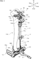
- FIG. 1 is a perspective view of a surgical instrument 1 according to an embodiment of the present disclosure.
- the surgical instrument 1 is used for knee replacement.
- Knee replacement is a surgical procedure to replace a malfunctioning knee of a patient with an artificial knee.
- FIGs. 1 and 2 (described later) schematically show a tibia 100 alone among the regions of the patient body. Other bones or soft tissue in the patient body, such as muscle, are not shown in the figures.
- Knee replacement involves cutting of portions at the proximal end of the tibia 100 and the distal end of the femur of the patient, and formation of mount surfaces on which an artificial knee or implants are placed.
- the artificial knee includes a tibial implant and a femoral implant (both not shown).
- the tibial implant is placed on the mount surface (not shown) at the proximal end of the tibia 100.
- the femoral implant is placed on the mount surface (not shown) at the distal end of the femur.
- the patient's knee is replaced with the artificial knee.
- Being proximal herein refers to being closer to the trunk, and being distal herein refers to being farther from the trunk.
- knee replacement involves formation of a mount surface for a tibial implant at the proximal end of the tibia 100.
- the surgical instrument 1 is placed on the tibia 100 to cut part of the proximal end of the tibia 100 with a cutting instrument such as a bone saw (not shown).
- the surgical instrument 1 including a cutting guide 13 that guides a cutting instrument in a cutting direction is used to cut part of the proximal end of the tibia 100 with the cutting instrument.
- the surgical instrument 1 will now be described in detail.
- FIG. 2 is a side view of the surgical instrument 1 shown in FIG. 1 with the patient's tibia 100 to schematically show a use example of the surgical instrument 1.
- the directions pointed with up and down arrows respectively indicate the upper and lower portions of the patient body.
- the directions pointed with right and left arrows respectively indicate the right and left portions of the patient body.
- the directions pointed with front and rear arrows respectively indicate the front and rear portions of the patient body. More specifically, the up-down direction, right-left direction, and front-rear direction throughout the drawings indicate the up-down or vertical direction, right-left or lateral direction, and front-rear direction with respect to the patient body.
- the surgical instrument 1 includes a rod unit 11, an attachment 12, a cutting guide 13, a front-rear rod unit 14, and a fastener 15.
- the rod unit 11 includes a vertical rod 17, a shaft coupler 18, and a front-rear rod support 20.
- the vertical rod 17 is placed to extend in a first direction with the surgical instrument 1 placed along the tibia 100.
- the first direction corresponds to the vertical direction.
- the first direction also extends along the tibia 100 of the human body.
- the vertical rod 17 includes a first rod 17a, a second rod 17b, and a third rod 17c.
- the first rod 17a, the second rod 17b, and the third rod 17c are rod-shaped members linearly extending in, for example, the first direction.
- the first rod 17a and the second rod 17b are coaxially coupled in series.
- the first rod 17a and the second rod 17b have, for example, a substantially polygonal-columnar or cylindrical shape.
- the first rod 17a is, for example, a substantially polygonal-columnar member.
- the second rod 17b is, for example, a substantially cylindrical member.
- the first rod 17a is received in the second rod 17b from a lower end or a first end of the second rod 17b.
- the second rod 17b can change its position in the axial direction relative to the first rod 17a. More specifically, the first rod 17a and the second rod 17b in the vertical rod 17 are extendable and retractable in the axial direction.
- the first rod 17a is received in the second rod 17b.
- the second rod 17b may be received in the first rod 17a.
- the vertical rod 17 with the above structure can change its length in the axial direction. More specifically, when placed along the tibia 100, the vertical rod 17 can adjust its length in the first direction. More specifically, the vertical rod 17 can adjust its length by accommodating the first rod 17a in the second rod 17b.
- the vertical rod 17 includes a first vertical rod lock 17d at a joint portion between the first rod 17a and the second rod 17b.
- the vertical rod 17 also includes a second vertical rod lock 17e at a joint portion between the second rod 17b and the third rod 17c.
- the first vertical rod lock 17d can position the second rod 17b in the axial direction relative to the first rod 17a as intended by a surgeon.
- the vertical rod 17 can change the position of the second rod 17b relative to the first rod 17a stepwise in response to the surgeon handling the first vertical rod lock 17d.
- the third rod 17c extends from the upper end of the second rod 17b in the direction in which the second rod 17b extends. More specifically, the second rod 17b and the third rod 17c are coaxially coupled in series.
- the third rod 17c is a rod-shaped member with, for example, a substantially rectangular cross-section.
- the third rod 17c is received in the second rod 17b from the upper end or a second end of the second rod 17b.
- the third rod 17c can change its position in the axial direction relative to the second rod 17b. More specifically, the third rod 17c can adjust its length by being accommodated in the second rod 17b.
- the second rod 17b and the third rod 17c in the vertical rod 17 are extendable and retractable in the axial direction.
- the third rod 17c is received in the second rod 17b.
- the second rod 17b may be received in the third rod 17c.
- the second vertical rod lock 17e can position the third rod 17c in the axial direction relative to the second rod 17b as intended by a surgeon.
- the vertical rod 17 can change the position of the third rod 17c relative to the second rod 17b stepwise in response to the surgeon handling the second vertical rod lock 17e.
- the shaft coupler 18 couples the vertical rod 17 to the attachment 12.
- the attachment 12 includes a shaft 21.
- the shaft coupler 18 can couple the vertical rod 17 to the attachment 12 by coupling the first rod 17a to the shaft 21.
- the shaft 21 extends in a second direction.
- the second direction is a direction crossing the tibia 100 of the human body, or the front-rear direction of the human body.
- the shaft coupler 18 couples the shaft 21 to one end of the first rod 17a, with the axial direction of the shaft 21 orthogonal to the axial direction of the first rod 17a.
- the shaft coupler 18 couples the shaft 21 to the first rod 17a at the one end of the first rod 17a (or a lower end of the first rod 17a placed in the vertical direction of the human body) opposite to the other end coupled to the second rod 17b.
- the shaft coupler 18 has a through-hole in which the shaft 21 is slidable in the axial direction.
- the surgical instrument 1 can change the position of the vertical rod 17 in the axial direction of the shaft 21 by changing the position of the shaft coupler 18 relative to the shaft 21.
- the surgical instrument 1 along the tibia 100 can adjust the position of the vertical rod 17 in the second direction relative to the attachment 12.
- the shaft coupler 18 also includes a unit for positioning the first rod 17a in the second direction relative to the shaft 21 as intended by a surgeon.
- the shaft coupler 18 includes an engagement portion that engages the shaft 21 and the first rod 17a with each other under a spring force, and a pressing operation portion that disengages the shaft 21 and the first rod 17a from each other under a spring force.
- the surgical instrument 1 can change the position of the vertical rod 17 in the second direction relative to the attachment 12 stepwise.
- the front-rear rod support 20 couples the vertical rod 17 to the front-rear rod unit 14 (described later) to cause the vertical rod 17 to support the front-rear rod unit 14.
- the front-rear rod support 20 includes, for example, a block with an angular tube shape.
- the front-rear rod support 20 is located on the upper end of the third rod 17c. More specifically, the front-rear rod support 20 is placed on the third rod 17c with the fastener 15 in between.
- the front-rear rod support 20 has a hole receiving the front-rear rod unit 14 slidably in the axial direction.
- the front-rear rod support 20 holds the front-rear rod unit 14 above the third rod 17c in a manner slidable in the axial direction of the front-rear rod unit 14.
- the position of the front-rear rod unit 14 is changed relative to the front-rear rod support 20, the position of the front-rear rod unit 14 is changed relative to the vertical rod 17 in the direction crossing the axial direction of the third rod 17c.
- the front-rear rod support 20 includes a unit that adjusts the position of the front-rear rod unit 14 relative to the third rod 17c.
- the front-rear rod support 20 includes a positioner 26 that is rotatable by the surgeon to position and fix the front-rear rod unit 14 in the front-rear direction.
- the attachment 12 shown in FIGs. 1 and 2 is a unit attached to the rod unit 11 at a first end of the vertical rod 17 to be fixed to the ankle joint.
- the attachment 12 includes the shaft 21, a pair of clamps (22a and 22b), and a frame 23.
- the shaft 21 extends linearly and includes a columnar portion with a substantially rectangular cross section.
- the shaft 21 has the axis in the second direction.
- the shaft 21 is coupled to the lower end of the first rod 17a in the vertical rod 17 with the shaft coupler 18.
- the attachment 12 is attached to the rod unit 11 at the lower end of the vertical rod 17.
- the pair of clamps (22a and 22b) hold the ankle joint between them in the lateral direction to fix the attachment 12 with respect to the ankle joint.
- the pair of clamps (22a and 22b) are located at the rear of the frame 23.
- the frame 23 is located behind the lower end of the vertical rod 17 and behind the shaft 21.
- the frame 23 is a plate extending in a direction perpendicular to the directions in which the vertical rod 17 and the shaft 21 extend.
- the frame 23 couples the pair of clamps (22a and 22b) and the shaft 21.
- the shaft 21 has its end attached to the center of the frame 23.
- the frame 23 is in front of the ankle joint.
- the pair of clamps (22a and 22b) are located on the right and left sides of the ankle joint.
- the frame 23 has, on its upper surface, graduations to measure the dimension by which the pair of clamps (22a and 22b) move.
- Each of the clamps (22a and 22b) is cantilevered and slidably attached to the frame 23.
- the clamps (22a and 22b) include a pair of knobs (24a and 24b) that allow the respective clamps (22a and 22b) to slide relative to the frame 23.
- the soft tissue around the tibia 100 are not shown in the figures, the attachment 12 is fixed to the ankle joint through the soft tissue outside.
- the cutting guide 13 guides the cutting instrument, such as a bone saw, in the cutting direction when the cutting instrument cuts part of the proximal end of the tibia 100.
- the cutting guide 13 includes a connector 13a, a slit former 13b, and a guide slot 13c.
- the cutting guide 13 is attached to the upper end of the vertical rod 17 (third rod 17c).
- the cutting guide 13 attached to the vertical rod 17 is cantilevered to extend frontward from the vertical rod 17 when the surgical instrument 1 is placed along the tibia 100.
- the connector 13a connects the cutting guide 13 to the vertical rod 17.
- the connector 13a includes a movable piece 13d, which slidably rotates relative to the third rod 17c, and a movable-piece operation portion 13e, which can slidably operate the movable piece 13d.
- the connector 13a is rotatable relative to the rod unit 11 to adjust the angle of the cutting guide 13 (or the cutting instrument) to the tibia 100 using the movable piece 13d and the movable-piece operation portion 13e.
- the cutting guide 13 connected to the third rod 17c with the connector 13a is rotatable by the surgeon rotating the movable-piece operation portion 13e.
- the slit former 13b is a plate that gradually curves and extends from the connector 13a.
- the slit former 13b gradually curves and extends in conformance with the periphery of the tibia 100 from the front of the tibia 100 to the right or the left.
- the slit former 13b has a slit or a guide slot 13c extending through to guide the cutting instrument in the cutting direction when the cutting instrument cuts part of the proximal end of the tibia 100.
- the cutting instrument is received in and along the guide slot 13c to cut part of the proximal end of the tibia 100.
- the cut part of the proximal end of the tibia 100 serves as the mount surface for the tibial implant on the tibia 100.
- the front-rear rod unit 14 extends linearly and includes, for example, a square-bar portion with a substantially rectangular cross section.
- the front-rear rod unit 14 is attached to the front-rear rod support 20 and is received in the hole in the front-rear rod support 20.
- the front-rear rod unit 14 is attached to the rod unit 11 at the upper end of the vertical rod 17 with the fastener 15.
- the front-rear rod unit 14 is supported by the front-rear rod support 20 and is received in the hole in the front-rear rod support 20.
- the front-rear rod unit 14 is attached to the rod unit 11, with, for example, the axial direction orthogonal to the axial direction of the third rod 17c.
- the front-rear rod unit 14 has its axial direction extending in the second direction when the surgical instrument 1 is placed along the tibia 100.
- the front-rear rod unit 14 may be fastened to the proximal end of the tibia 100 with a pin (not shown).
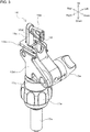
- FIG. 3 is a partially enlarged perspective view of the surgical instrument 1 shown in FIG. 1 .
- FIG. 4 is a partially enlarged front view of the surgical instrument 1 shown in FIG. 1 .
- FIGs. 3 and 4 show the surgical instrument 1 excluding part of the cutting guide 13 and the front-rear rod unit 14, and show part of the cutting guide 13 and the fastener 15 located at a second end of the rod unit 11.
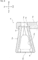
- FIG. 5 is a cross-sectional view of the surgical instrument 1 taken along line A-A as viewed in the direction indicated by arrows in FIG. 4 .
- FIGs. 6A and 6B are partially enlarged cross-sectional views of the surgical instrument 1 shown in FIG. 1 when the surgical instrument 1 is swung relative to a pin 25 fastened to the tibia 100.
- the fastener 15 in the present embodiment is located at the upper end of the rod unit 11. More specifically, the fastener 15 is located on the third rod 17c and a rod connector 15a adjacent to and parallel to the third rod 17c. The fastener 15 is fastened to the proximal end of the tibia 100 with the pin 25 on the front of the tibia 100.
- the fastener 15 includes a movement restrictor 15b having a through-hole 16 and the pin 25.
- the through-hole 16 in the movement restrictor 15b extends in the second direction crossing the first direction and substantially parallel to the front-rear direction of the tibia.
- the pin 25 is placed in the through-hole 16, with the tip received in the tibia 100. More specifically, the pin 25 is placed in the through-hole 16 from the front to the rear to be received in the proximal end of the tibia 100.
- the pin 25 is not shown in FIGs. 3 to 5 .
- the movement restrictor 15b restricts the swinging direction of the surgical instrument 1 relative to the tibia 100 when the surgical instrument 1 is held to be swingable relative to the tibia 100 with the pin 25 placed in the through-hole 16.
- the through-hole 16 has a first opening 16a near the tibia 100, and a second opening 16b at an opposite end.
- the second opening 16b has a larger diameter than the first opening 16a.
- the through-hole 16 has a cross-sectional area increasing from the first opening 16a toward the second opening 16b.
- the cross-sectional area of the through-hole 16 taken in the first direction continuously increases from the rear toward the front.
- the opening of the through-hole 16 is larger than the profile of the pin to allow the fastener 15 to move about a portion of contact between the through-hole 16 and the pin 25 when the pin 25 is received in the tibia 100. More specifically, a portion of the pin 25 in contact with the through-hole 16 is a portion on the outer periphery received in the through-hole 16 and near the first opening 16a of the through-hole 16. A portion of the through-hole 16 in contact with the pin 25 is the inner periphery at the edge of the first opening 16a. As shown in FIGs. 6A and 6B , a clearance left between the fastener 15 and the pin 25 allows the surgical instrument 1 to be held swingable relative to the tibia 100 about a portion of contact between the through-hole 16 and the pin 25.
- a surgical instrument with the structure that forms the basis of the surgical instrument according to one or more embodiments of the present disclosure has, for example, a through-hole supporting a pin with substantially the same size as the profile of the pin.
- This structure causes difficulties in finely adjusting the position of the surgical instrument after the surgical instrument is fastened.
- the surgical instrument 1 according to one or more embodiments of the present disclosure with the above structure enables fine adjustment of the position of the surgical instrument 1 with the operation on the shaft coupler 18 after the surgical instrument 1 is fastened to the tibia 100 as well.
- the movement restrictor 15b has an oval cross section taken perpendicular to the second direction.
- the through-hole 16 in the movement restrictor 15b has a cross-sectional area continuously increasing in the first direction from the rear toward the front.
- the movement restrictor 15b has windows 15d in its wall surface to enable visual identification of the received pin 25.
- the first opening 16a has a shape in conformance with the profile of the pin 25. More specifically, the first opening 16a and the profile of the pin 25 have the same or similar shapes.
- the profile of the first opening 16a in the present embodiment conforms to the profile of the pin 25 with a cylindrical shape. More specifically, the profile of the first opening 16a has a circular cross section taken perpendicular to the second direction.
- the second opening 16b has, for example, an oval shape with the major axis extending in the first direction. More specifically, the second opening 16b has an elliptical shape.
- the rod connector 15a receives the movement restrictor 15b on the front, or opposite to the tibia 100.
- the rod connector 15a has a communicating hole 15e extending in the second direction and communicating with the through-hole 16 in the movement restrictor.
- the movement restrictor 15b is fitted and attached to a setback 15f on the front of the rod connector 15a.
- the setback 15f is coaxial with the communicating hole 15e and has a larger diameter than the communicating hole 15e. More specifically, the outer periphery of the movement restrictor 15b at the first opening has the same shape as the profile of the inner periphery of the setback 15f to be fitted into and fixed to the setback 15f.
- the surgical instrument 1 is used for knee replacement in, for example, the procedure described below.
- the angle of the cutting guide 13 is fixed. More specifically, the connector 13a is rotated with the movable-piece operation portion 13e to set and fix the angle of the cutting guide 13 to achieve the angle of a cut plane of the tibia 100 determined before surgery.
- the attachment 12 is fixed to the patient's ankle joint. More specifically, the surgeon handles the pair of clamps (22a and 22b) to fix the attachment 12 to the patient's ankle joint.
- the surgeon adjusts the position of the vertical rod 17 to arrange the vertical rod 17 substantially parallel to the bone axis of the patient's tibia 100 when viewed from the front.
- the position of the shaft 21 relative to the attachment 12 is adjusted, and the length of the vertical rod 17 is adjusted by the first vertical rod lock 17d.
- the position of the vertical rod 17 in the lateral direction relative to the tibia 100 is adjusted.
- the pin 25 is placed into the through-hole 16 in the fastener 15 to fasten the fastener 15 to the proximal end of the tibia 100.
- the through-hole 16 has a cross-sectional area continuously increasing from the first opening 16a toward the second opening 16b.
- the second opening 16b of the through-hole 16 has an oval shape with the major axis extending in the first direction.
- the cutting guide 13 is restricted from moving in the lateral direction but can move in the front-rear direction along the shaft 21.
- the position of the shaft coupler 18 in the front-rear direction is adjusted to arrange the vertical rod 17 substantially parallel to the bone axis of the patient's tibia 100 when viewed from laterally.
- the position of the vertical rod 17 is adjusted.
- the length of the vertical rod 17 is also adjusted.
- the above procedure adjusts the position of the vertical rod 17 in the front-rear and lateral directions relative to the bone axis, and the position of the cutting guide 13 relative to the tibia 100 to an appropriate position.
- the proximal end of the tibia 100 is then cut by the cutting instrument such as a bone saw.
- the surgical instrument 1 can be finely adjusted in the second direction after being fastened with the pin 25 as well.
- This structure facilitates position adjustment of the cutting guide 13 for cutting the proximal end of the tibia 100 in knee replacement.
- adjusting the length of the third rod 17c with the second vertical rod lock 17e enables fine adjustment of the length of the surgical instrument 1 in the first direction.
- the surgical instrument 1 includes the rod unit 11 extending in the first direction or a direction to be along the tibia 100 of the human body, the attachment 12 to be attached to the ankle joint, and the fastener 15 to be fastened to the proximal end of the tibia 100.
- the fastener 15 has the through-hole 16, which can receive the pin 25, and the through-hole 16 has an opening larger than the profile of the pin 25.
- the fastener 15 is movable relative to the pin 25 fastened to the proximal end of the tibia 100 about a portion of contact between the through-hole 16 and the pin 25.
- the surgical instrument 1 is held movable and swingable relative to the tibia 100.
- the position and orientation of the surgical instrument 1 relative to the tibia 100 can be adjusted by moving the surgical instrument 1.
- the surgical instrument 1 thus further facilitates position adjustment relative to the bone.
- the through-hole 16 has the first opening 16a nearer the tibia, and the second opening 16b at the opposite end.
- the second opening 16b has a larger diameter than the first opening 16a.
- the surgical instrument 1 can move a larger distance at the second opening with a larger opening area than at the first opening 16a, with the pin 25 received in the through-hole 16. More specifically, the surgical instrument 1 is swingable relative to the pin 25. Thus, the surgeon can adjust the position of the surgical instrument 1 while swinging the surgical instrument 1 relative to the pin 25.
- the second opening 16b has a larger dimension in the first direction and has an oval shape.
- the surgeon can swing or move the surgical instrument 1 in the first direction relative to the pin 25 received in the through-hole 16, while restricting the surgical instrument 1 from moving in directions other than the first direction.
- the first opening 16a has a shape in conformance with the profile of the pin 25.
- the range within which the surgical instrument 1 is movable relative to the pin 25 decreases toward the first opening 16a.
- This structure enables swinging of the surgical instrument 1 relative to the pin 25 but restricts the surgical instrument 1 from sliding in the vertical and lateral directions.
- the through-hole 16 continuously becomes larger from the first opening 16a toward the second opening 16b.
- the through-hole 16 has no protrusion inside. This structure does not largely restrict movement of the surgical instrument 1 also when the surgical instrument 1 is swung.
- the surgical instrument 1 includes the rod unit 11 extending in the first direction or the direction to be along the tibia 100 of the human body, the attachment 12 to be attached to the ankle joint, and the fastener 15 to be fastened to the proximal end of the tibia 100.
- the fastener 15 has the through-hole 16, which can receive the pin 25, and the through-hole 16 has an opening larger than the profile of the pin 25.
- the fastener 15 is movable relative to the pin 25 fastened to the proximal end of the tibia 100 about a portion of contact between the through-hole 16 and the pin 25.
- the position and the orientation of the surgical instrument 1 relative to the tibia 100 can be adjusted by moving the surgical instrument 1.
- the surgical instrument 1 facilitates position adjustment to the bone.
- the through-hole 16 has the first opening 16a nearer the tibia, and the second opening 16b at the opposite end.
- the second opening 16b has a larger opening area than the first opening 16a.
- the surgical instrument 1 can move a larger distance at the second opening 16b with a larger opening area than at the first opening 16a, with the pin 25 received in the through-hole 16. More specifically, the surgical instrument 1 is swingable relative to the pin 25. Thus, the surgeon can adjust the position of the surgical instrument 1 while swinging the surgical instrument 1 relative to the pin 25.
- the structure according to the above embodiment includes the pin 25 and the movement restrictor 15b with the through-hole 16, but the structure is not limited to the above example. More specifically, for example, the fastener 15 includes the pin 25 as its component. In one modification, for example, the fastener 15 may include the movement restrictor 15b with the through-hole 16. More specifically, the surgical instrument in this modification includes the rod unit 11, the attachment 12, and the fastener 15. The rod unit 11 extends linearly in the first direction to be along the tibia 100 of the human body. The attachment 12 is located at a first end of the rod unit 11 to be attached to the ankle joint.
- the fastener 15 is located at a second end of the rod unit 11 to be fastened to the proximal end of the tibia 100.
- the second end is the upper end when the vertical rod 17 is placed in the vertical direction of the human body.
- the fastener 15 has the through-hole 16 extending in the second direction crossing the first direction.
- the fastener 15 can receive the pin 25 having the tip to be received in the tibia 100.
- the through-hole 16 has an opening larger than the profile of the pin 25 to allow the fastener 15 to move about a portion of contact between the through-hole 16 and the pin 25 when the pin 25 is received in the tibia 100.
- the through-hole 16 has the first opening 16a to be nearer the tibia 100, and the second opening 16b at the opposite end to the first opening 16a.
- the second opening 16b has a larger diameter than the first opening 16a.
- the surgical instrument according to the present modification includes the rod unit 11 extending in the first direction or a direction to be along the tibia 100 of the human body, the attachment 12 located at the first end of the rod unit 11 to be attached to the ankle joint, and the fastener 15 located at the second end of the rod unit 11 to be fastened to the proximal end of the tibia 100.
- the fastener 15 has the through-hole 16, which can receive the pin 25, and the through-hole 16 has the opening larger than the profile of the pin 25.
- a clearance left between the fastener 15 and the pin 25 allows the fastener 15 to move relative to the pin 25 fastened to the proximal end of the tibia 100 about a portion of contact between the through-hole 16 and the pin 25.
- the surgical instrument is held movable and swingable relative to the tibia 100 to adjust its orientation and position in the first direction.
- the surgical instrument with the above structure can thus further facilitate position adjustment relative to a bone.
- the through-hole 16 has the first opening 16a nearer the tibia 100, and the second opening 16b at the opposite end to the first opening 16a.
- the second opening 16b has a larger opening area than the first opening 16a.
- the surgical instrument can move a larger distance at the second opening 16b with a larger opening area than at the first opening 16a, with the pin 25 received in the through-hole 16. More specifically, the surgical instrument is swingable relative to the pin 25. Thus, the surgeon can adjust the position of the surgical instrument while swinging the surgical instrument relative to the pin 25.
- the through-hole 16 in the movement restrictor 15b has a cross-sectional area continuously increasing in the first direction from the rear toward the front.
- this example is not limitative.
- the movement restrictor 15b may have a hollow cylindrical shape, and the through-hole 16 in the movement restrictor 15b may have a uniform opening dimension in the front-rear direction.
- the movement restrictor 15b has an oval cross section taken perpendicular to the second direction.
- this example is not limitative.
- the movement restrictor 15b may have a rectangular cross section taken perpendicular to the second direction.
- a surgical instrument includes a rod unit extending in a first direction to be along a tibia of a human body, an attachment located at a first end of the rod unit to be attached to an ankle joint, and a fastener located at a second end of the rod unit to be fastened to a proximal end of the tibia.
- the fastener has a through-hole extending in a second direction crossing the first direction, and a pin placeable in the through-hole and having a tip to be received in the tibia.
- the through-hole has an opening larger than a profile of the pin to allow the fastener to move about a portion of contact between the through-hole and the pin when the pin is received in the tibia.
- the surgical instrument includes a rod unit extending in a first direction to be along a tibia of a human body, an attachment to be attached to an ankle joint, and a fastener to be fastened to a proximal end of the tibia.
- the fastener has a through-hole that can receive a pin, and the through-hole has an opening larger than a profile of the pin. The fastener is thus movable relative to the pin fastened to the proximal end of the tibia about a portion of contact between the through-hole and the pin. After the pin is fastened to the proximal end of the tibia as well, the surgical instrument is held movable and swingable relative to the tibia and can adjust its position and orientation relative to the tibia.
- the surgical instrument with the above structure can further facilitate position adjustment relative to a bone.
- the through-hole may have a first opening to be nearer the tibia, and a second opening at an opposite end to the first opening, and the second opening may have a larger diameter than the first opening.
- the through-hole has a first opening nearer the tibia, and a second opening at the opposite end.
- the second opening has a larger diameter than the first opening.
- the second opening may have an oval shape with the major axis extending in the first direction.
- the second opening has a larger dimension in the first direction.
- the second opening has an oval shape.
- the first opening may have a shape in conformance with the profile of the pin.
- the first opening has a shape in conformance with the profile of the pin.
- the range within which the surgical instrument is movable relative to the pin decreases toward the first opening.
- the surgical instrument is swingable relative to the pin but is restricted from sliding in the vertical and lateral directions.
- the through-hole may have a cross-sectional area continuously increasing from the first opening toward the second opening.
- the through-hole continuously becomes larger from the first opening toward the second opening.
- the through-hole has no protrusion inside. This structure does not largely restrict movement of the surgical instrument also when the surgical instrument is swung.
- the second direction may extend in a front-rear direction of the tibia.
- the surgical instrument can move in a front-rear direction of the tibia.
- the surgical instrument may include a cutting guide to guide a cutting instrument to cut the tibia.
- This structure can facilitate adjustment of the angle and the cut position of the tibia.
- the surgical instrument may include a front-rear rod unit slidable relative to the fastener in the second direction.
- the front-rear rod unit can be used to check the position of the proximal end of the tibia, and accurately determine the cut position.
- a surgical instrument includes a rod unit extending in a first direction to be along a tibia of human body, an attachment located at a first end of the rod unit to be attached to an ankle joint, and a fastener located at a second end of the rod unit to be fastened to a proximal end of the tibia.
- the fastener has a through-hole extending in a second direction crossing the first direction, and receiving a pin having a tip to be received in the tibia.
- the through-hole has an opening larger than a profile of the pin to allow the fastener to move about a portion of contact between the through-hole and the pin when the pin is received in the tibia.
- the through-hole has a first opening to be nearer the tibia, and a second opening at an opposite end to the first opening.
- the second opening has a larger diameter than the first opening.
- the surgical instrument includes a rod unit extending in a first direction to be along a tibia of a human body, an attachment to be attached to an ankle joint, and a fastener to be fastened to a proximal end of the tibia.
- the fastener has a through-hole that can receive a pin, and the through-hole has an opening larger than a profile of the pin. The fastener is thus movable about a portion of contact between the through-hole and the pin relative to the pin fastened to the proximal end of the tibia. After the pin is fastened to the proximal end of the tibia as well, the surgical instrument is movable and can adjust its position and orientation relative to the tibia.
- the surgical instrument with the above structure can thus further facilitate position adjustment relative to the bone.
- the through-hole has a first opening nearer the tibia, and a second opening at the opposite end to the first opening.
- the second opening has a larger opening area than the first opening.
- the surgical instrument according to one or more embodiments of the present disclosure can facilitate position adjustment.
- the present disclosure is widely applicable to a surgical instrument for knee replacement.
Landscapes
- Health & Medical Sciences (AREA)
- Life Sciences & Earth Sciences (AREA)
- Surgery (AREA)
- Orthopedic Medicine & Surgery (AREA)
- Transplantation (AREA)
- Biomedical Technology (AREA)
- Animal Behavior & Ethology (AREA)
- Oral & Maxillofacial Surgery (AREA)
- Veterinary Medicine (AREA)
- Engineering & Computer Science (AREA)
- Physical Education & Sports Medicine (AREA)
- Heart & Thoracic Surgery (AREA)
- Public Health (AREA)
- General Health & Medical Sciences (AREA)
- Nuclear Medicine, Radiotherapy & Molecular Imaging (AREA)
- Molecular Biology (AREA)
- Medical Informatics (AREA)
- Dentistry (AREA)
- Cardiology (AREA)
- Vascular Medicine (AREA)
- Surgical Instruments (AREA)
- Prostheses (AREA)
Abstract
Description
- The present disclosure relates to a surgical instrument for knee replacement.
- A known surgical instrument for knee replacement includes a cutting guide that guides a cutting instrument for cutting the proximal end of the tibia.
- A surgical instrument according to an aspect of the present disclosure includes a rod unit extending in a first direction along a tibia of a human body, an attachment located at a first end of the rod unit that is attachable to an ankle joint, and a fastener located at a second end of the rod unit that is fasten-able to a proximal end of the tibia. The fastener has a through-hole extending in a second direction that crosses the first direction, and a pin that is arranged in the through-hole and that has a tip which is received in the tibia. The through-hole has an opening larger than a profile of the pin to allow the fastener to move about a portion of contact between the through-hole and the pin when the pin is received in the tibia.
- A surgical instrument according to another aspect of the present disclosure includes a rod unit extending in a first direction to be along a tibia of a human body, an attachment located at a first end of the rod unit that is attachable to an ankle joint, and a fastener located at a second end of the rod unit that is fasten-able to a proximal end of the tibia. The fastener has a through-hole extending in a second direction that crosses the first direction, and the through hole accommodating a pin having a tip to be received in the tibia. The through-hole has an opening larger than a profile of the pin to allow the fastener to move about a portion of contact between the through-hole and the pin when the pin is received in the tibia. The through-hole has a first opening that is nearer the tibia, and a second opening at an opposite end to the first opening. A diameter of the second opening is larger than a diameter of the first opening.
- The objects, features, and advantages of the present disclosure will become more apparent from the following detailed description and the drawings.
-
FIG. 1 is a perspective view of a surgical instrument according to one embodiment of the present disclosure. -
FIG. 2 is a side view of the surgical instrument shown inFIG. 1 with a patient's tibia to schematically show a use example of the surgical instrument. -
FIG. 3 is a partially enlarged perspective view of the surgical instrument shown inFIG. 1 . -
FIG. 4 is a partially enlarged front view of the surgical instrument shown inFIG. 1 . -
FIG. 5 is a cross-sectional view of the surgical instrument taken along line A-A as viewed in the direction indicated by arrows inFIG. 4 . -
FIG. 6A is a partially enlarged cross-sectional view of the surgical instrument shown inFIG. 1 when the surgical instrument is swung relative to a pin fastened to the tibia. -
FIG. 6B is a partially enlarged cross-sectional view of the surgical instrument shown inFIG. 1 when the surgical instrument is swung relative to a pin fastened to the tibia. - One or more embodiments of the present disclosure will now be described with reference to the drawings. The present disclosure is widely applicable to a surgical instrument for knee replacement.
- First, a surgical instrument with a structure that forms the basis of a surgical instrument according to one or more embodiments of the present disclosure will be described.
- The surgical instrument with the structure that forms the basis of the surgical instrument according to one or more embodiments of the present disclosure is used in knee replacement in which the proximal end of the tibia and the distal end of the femur are cut and then an artificial knee or implants are attached to the cut portions. The surgical instrument including a cutting guide for guiding a cutting instrument is used in cutting the proximal end of the tibia.
- For example, a known surgical instrument for knee replacement is used to position a cutting guide that guides a cutting instrument near the proximal end of the tibia. This surgical instrument includes a lower clamp, a positioning external rod, a tibia positioning shaft, and a cutting guide. The lower clamp is used to attach the surgical instrument to the ankle joint. The positioning external rod is fastened to the femur and extends parallel to the axis of the femur. The tibia positioning shaft includes a base positioner that can hold the positioning external rod. The cutting guide is positioned at an intended cutting position, with the positioning external rod held by the tibia positioning shaft. When the cutting guide is positioned, the surgical instrument is completely fastened to the tibia with the pin.
-
FIG. 1 is a perspective view of asurgical instrument 1 according to an embodiment of the present disclosure. Thesurgical instrument 1 is used for knee replacement. Knee replacement is a surgical procedure to replace a malfunctioning knee of a patient with an artificial knee.FIGs. 1 and2 (described later) schematically show atibia 100 alone among the regions of the patient body. Other bones or soft tissue in the patient body, such as muscle, are not shown in the figures. - Knee replacement involves cutting of portions at the proximal end of the
tibia 100 and the distal end of the femur of the patient, and formation of mount surfaces on which an artificial knee or implants are placed. The artificial knee includes a tibial implant and a femoral implant (both not shown). The tibial implant is placed on the mount surface (not shown) at the proximal end of thetibia 100. The femoral implant is placed on the mount surface (not shown) at the distal end of the femur. Thus, the patient's knee is replaced with the artificial knee. Being proximal herein refers to being closer to the trunk, and being distal herein refers to being farther from the trunk. - As described above, knee replacement involves formation of a mount surface for a tibial implant at the proximal end of the
tibia 100. To form the implant mount surface at the proximal end of thetibia 100, thesurgical instrument 1 is placed on thetibia 100 to cut part of the proximal end of thetibia 100 with a cutting instrument such as a bone saw (not shown). Thesurgical instrument 1 including acutting guide 13 that guides a cutting instrument in a cutting direction is used to cut part of the proximal end of thetibia 100 with the cutting instrument. Thesurgical instrument 1 will now be described in detail. -
FIG. 2 is a side view of thesurgical instrument 1 shown inFIG. 1 with the patient'stibia 100 to schematically show a use example of thesurgical instrument 1. - Throughout the drawings, the directions pointed with up and down arrows respectively indicate the upper and lower portions of the patient body. The directions pointed with right and left arrows respectively indicate the right and left portions of the patient body. The directions pointed with front and rear arrows respectively indicate the front and rear portions of the patient body. More specifically, the up-down direction, right-left direction, and front-rear direction throughout the drawings indicate the up-down or vertical direction, right-left or lateral direction, and front-rear direction with respect to the patient body.
- As shown in
FIGs. 1 and2 , thesurgical instrument 1 includes arod unit 11, anattachment 12, acutting guide 13, a front-rear rod unit 14, and afastener 15. - As shown in
FIGs. 1 and2 , therod unit 11 includes avertical rod 17, ashaft coupler 18, and a front-rear rod support 20. - The
vertical rod 17 is placed to extend in a first direction with thesurgical instrument 1 placed along thetibia 100. The first direction corresponds to the vertical direction. The first direction also extends along thetibia 100 of the human body. Thevertical rod 17 includes afirst rod 17a, asecond rod 17b, and athird rod 17c. Thefirst rod 17a, thesecond rod 17b, and thethird rod 17c are rod-shaped members linearly extending in, for example, the first direction. - The
first rod 17a and thesecond rod 17b are coaxially coupled in series. Thefirst rod 17a and thesecond rod 17b have, for example, a substantially polygonal-columnar or cylindrical shape. In the present embodiment, thefirst rod 17a is, for example, a substantially polygonal-columnar member. Thesecond rod 17b is, for example, a substantially cylindrical member. Thefirst rod 17a is received in thesecond rod 17b from a lower end or a first end of thesecond rod 17b. Thesecond rod 17b can change its position in the axial direction relative to thefirst rod 17a. More specifically, thefirst rod 17a and thesecond rod 17b in thevertical rod 17 are extendable and retractable in the axial direction. - In the present embodiment, the
first rod 17a is received in thesecond rod 17b. In some embodiments, thesecond rod 17b may be received in thefirst rod 17a. - The
vertical rod 17 with the above structure can change its length in the axial direction. More specifically, when placed along thetibia 100, thevertical rod 17 can adjust its length in the first direction. More specifically, thevertical rod 17 can adjust its length by accommodating thefirst rod 17a in thesecond rod 17b. Thevertical rod 17 includes a firstvertical rod lock 17d at a joint portion between thefirst rod 17a and thesecond rod 17b. Thevertical rod 17 also includes a secondvertical rod lock 17e at a joint portion between thesecond rod 17b and thethird rod 17c. - The first
vertical rod lock 17d can position thesecond rod 17b in the axial direction relative to thefirst rod 17a as intended by a surgeon. Thevertical rod 17 can change the position of thesecond rod 17b relative to thefirst rod 17a stepwise in response to the surgeon handling the firstvertical rod lock 17d. - The
third rod 17c extends from the upper end of thesecond rod 17b in the direction in which thesecond rod 17b extends. More specifically, thesecond rod 17b and thethird rod 17c are coaxially coupled in series. Thethird rod 17c is a rod-shaped member with, for example, a substantially rectangular cross-section. Thethird rod 17c is received in thesecond rod 17b from the upper end or a second end of thesecond rod 17b. Thethird rod 17c can change its position in the axial direction relative to thesecond rod 17b. More specifically, thethird rod 17c can adjust its length by being accommodated in thesecond rod 17b. Thesecond rod 17b and thethird rod 17c in thevertical rod 17 are extendable and retractable in the axial direction. - In the present embodiment, the
third rod 17c is received in thesecond rod 17b. In some embodiments, thesecond rod 17b may be received in thethird rod 17c. - The second
vertical rod lock 17e can position thethird rod 17c in the axial direction relative to thesecond rod 17b as intended by a surgeon. Thevertical rod 17 can change the position of thethird rod 17c relative to thesecond rod 17b stepwise in response to the surgeon handling the secondvertical rod lock 17e. - The
shaft coupler 18 couples thevertical rod 17 to theattachment 12. Theattachment 12 includes ashaft 21. Theshaft coupler 18 can couple thevertical rod 17 to theattachment 12 by coupling thefirst rod 17a to theshaft 21. - When the
surgical instrument 1 is placed along thetibia 100, theshaft 21 extends in a second direction. The second direction is a direction crossing thetibia 100 of the human body, or the front-rear direction of the human body. - The
shaft coupler 18 couples theshaft 21 to one end of thefirst rod 17a, with the axial direction of theshaft 21 orthogonal to the axial direction of thefirst rod 17a. Theshaft coupler 18 couples theshaft 21 to thefirst rod 17a at the one end of thefirst rod 17a (or a lower end of thefirst rod 17a placed in the vertical direction of the human body) opposite to the other end coupled to thesecond rod 17b. - The
shaft coupler 18 has a through-hole in which theshaft 21 is slidable in the axial direction. Thesurgical instrument 1 can change the position of thevertical rod 17 in the axial direction of theshaft 21 by changing the position of theshaft coupler 18 relative to theshaft 21. Thesurgical instrument 1 along thetibia 100 can adjust the position of thevertical rod 17 in the second direction relative to theattachment 12. - The
shaft coupler 18 also includes a unit for positioning thefirst rod 17a in the second direction relative to theshaft 21 as intended by a surgeon. For example, theshaft coupler 18 includes an engagement portion that engages theshaft 21 and thefirst rod 17a with each other under a spring force, and a pressing operation portion that disengages theshaft 21 and thefirst rod 17a from each other under a spring force. In response to the surgeon handling the pressing operation portion of theshaft coupler 18, thesurgical instrument 1 can change the position of thevertical rod 17 in the second direction relative to theattachment 12 stepwise. - The front-
rear rod support 20 couples thevertical rod 17 to the front-rear rod unit 14 (described later) to cause thevertical rod 17 to support the front-rear rod unit 14. The front-rear rod support 20 includes, for example, a block with an angular tube shape. The front-rear rod support 20 is located on the upper end of thethird rod 17c. More specifically, the front-rear rod support 20 is placed on thethird rod 17c with thefastener 15 in between. - The front-
rear rod support 20 has a hole receiving the front-rear rod unit 14 slidably in the axial direction. The front-rear rod support 20 holds the front-rear rod unit 14 above thethird rod 17c in a manner slidable in the axial direction of the front-rear rod unit 14. When the position of the front-rear rod unit 14 is changed relative to the front-rear rod support 20, the position of the front-rear rod unit 14 is changed relative to thevertical rod 17 in the direction crossing the axial direction of thethird rod 17c. - The front-
rear rod support 20 includes a unit that adjusts the position of the front-rear rod unit 14 relative to thethird rod 17c. For example, the front-rear rod support 20 includes apositioner 26 that is rotatable by the surgeon to position and fix the front-rear rod unit 14 in the front-rear direction. - The
attachment 12 shown inFIGs. 1 and2 is a unit attached to therod unit 11 at a first end of thevertical rod 17 to be fixed to the ankle joint. Theattachment 12 includes theshaft 21, a pair of clamps (22a and 22b), and aframe 23. - The
shaft 21 extends linearly and includes a columnar portion with a substantially rectangular cross section. When thesurgical instrument 1 is placed along thetibia 100, theshaft 21 has the axis in the second direction. As described above, theshaft 21 is coupled to the lower end of thefirst rod 17a in thevertical rod 17 with theshaft coupler 18. Thus, theattachment 12 is attached to therod unit 11 at the lower end of thevertical rod 17. - The pair of clamps (22a and 22b) hold the ankle joint between them in the lateral direction to fix the
attachment 12 with respect to the ankle joint. The pair of clamps (22a and 22b) are located at the rear of theframe 23. Theframe 23 is located behind the lower end of thevertical rod 17 and behind theshaft 21. Theframe 23 is a plate extending in a direction perpendicular to the directions in which thevertical rod 17 and theshaft 21 extend. Theframe 23 couples the pair of clamps (22a and 22b) and theshaft 21. Theshaft 21 has its end attached to the center of theframe 23. - The
frame 23 is in front of the ankle joint. The pair of clamps (22a and 22b) are located on the right and left sides of the ankle joint. Theframe 23 has, on its upper surface, graduations to measure the dimension by which the pair of clamps (22a and 22b) move. - Each of the clamps (22a and 22b) is cantilevered and slidably attached to the
frame 23. The clamps (22a and 22b) include a pair of knobs (24a and 24b) that allow the respective clamps (22a and 22b) to slide relative to theframe 23. Although the soft tissue around thetibia 100 are not shown in the figures, theattachment 12 is fixed to the ankle joint through the soft tissue outside. - The cutting
guide 13 guides the cutting instrument, such as a bone saw, in the cutting direction when the cutting instrument cuts part of the proximal end of thetibia 100. The cuttingguide 13 includes aconnector 13a, a slit former 13b, and aguide slot 13c. - The cutting
guide 13 is attached to the upper end of the vertical rod 17 (third rod 17c). The cuttingguide 13 attached to thevertical rod 17 is cantilevered to extend frontward from thevertical rod 17 when thesurgical instrument 1 is placed along thetibia 100. - The
connector 13a connects the cuttingguide 13 to thevertical rod 17. Theconnector 13a includes amovable piece 13d, which slidably rotates relative to thethird rod 17c, and a movable-piece operation portion 13e, which can slidably operate themovable piece 13d. Theconnector 13a is rotatable relative to therod unit 11 to adjust the angle of the cutting guide 13 (or the cutting instrument) to thetibia 100 using themovable piece 13d and the movable-piece operation portion 13e. Thus, the cuttingguide 13 connected to thethird rod 17c with theconnector 13a is rotatable by the surgeon rotating the movable-piece operation portion 13e. - The slit former 13b is a plate that gradually curves and extends from the
connector 13a. The slit former 13b gradually curves and extends in conformance with the periphery of thetibia 100 from the front of thetibia 100 to the right or the left. - The slit former 13b has a slit or a
guide slot 13c extending through to guide the cutting instrument in the cutting direction when the cutting instrument cuts part of the proximal end of thetibia 100. Upon completion of the position adjustment of thesurgical instrument 1 to thetibia 100, the cutting instrument is received in and along theguide slot 13c to cut part of the proximal end of thetibia 100. The cut part of the proximal end of thetibia 100 serves as the mount surface for the tibial implant on thetibia 100. - With reference to
FIGs. 1 and2 , the front-rear rod unit 14 extends linearly and includes, for example, a square-bar portion with a substantially rectangular cross section. The front-rear rod unit 14 is attached to the front-rear rod support 20 and is received in the hole in the front-rear rod support 20. Thus, the front-rear rod unit 14 is attached to therod unit 11 at the upper end of thevertical rod 17 with thefastener 15. - The front-
rear rod unit 14 is supported by the front-rear rod support 20 and is received in the hole in the front-rear rod support 20. Thus, the front-rear rod unit 14 is attached to therod unit 11, with, for example, the axial direction orthogonal to the axial direction of thethird rod 17c. Thus, the front-rear rod unit 14 has its axial direction extending in the second direction when thesurgical instrument 1 is placed along thetibia 100. The front-rear rod unit 14 may be fastened to the proximal end of thetibia 100 with a pin (not shown). -
FIG. 3 is a partially enlarged perspective view of thesurgical instrument 1 shown inFIG. 1 .FIG. 4 is a partially enlarged front view of thesurgical instrument 1 shown inFIG. 1 .FIGs. 3 and4 show thesurgical instrument 1 excluding part of the cuttingguide 13 and the front-rear rod unit 14, and show part of the cuttingguide 13 and thefastener 15 located at a second end of therod unit 11.FIG. 5 is a cross-sectional view of thesurgical instrument 1 taken along line A-A as viewed in the direction indicated by arrows inFIG. 4 .FIGs. 6A and 6B are partially enlarged cross-sectional views of thesurgical instrument 1 shown inFIG. 1 when thesurgical instrument 1 is swung relative to apin 25 fastened to thetibia 100. - The
fastener 15 in the present embodiment is located at the upper end of therod unit 11. More specifically, thefastener 15 is located on thethird rod 17c and arod connector 15a adjacent to and parallel to thethird rod 17c. Thefastener 15 is fastened to the proximal end of thetibia 100 with thepin 25 on the front of thetibia 100. - The
fastener 15 includes amovement restrictor 15b having a through-hole 16 and thepin 25. The through-hole 16 in themovement restrictor 15b extends in the second direction crossing the first direction and substantially parallel to the front-rear direction of the tibia. Thepin 25 is placed in the through-hole 16, with the tip received in thetibia 100. More specifically, thepin 25 is placed in the through-hole 16 from the front to the rear to be received in the proximal end of thetibia 100. Thepin 25 is not shown inFIGs. 3 to 5 . - The
movement restrictor 15b restricts the swinging direction of thesurgical instrument 1 relative to thetibia 100 when thesurgical instrument 1 is held to be swingable relative to thetibia 100 with thepin 25 placed in the through-hole 16. - The through-
hole 16 has afirst opening 16a near thetibia 100, and asecond opening 16b at an opposite end. Thesecond opening 16b has a larger diameter than thefirst opening 16a. More specifically, the through-hole 16 has a cross-sectional area increasing from thefirst opening 16a toward thesecond opening 16b. The cross-sectional area of the through-hole 16 taken in the first direction continuously increases from the rear toward the front. - The opening of the through-
hole 16 is larger than the profile of the pin to allow thefastener 15 to move about a portion of contact between the through-hole 16 and thepin 25 when thepin 25 is received in thetibia 100. More specifically, a portion of thepin 25 in contact with the through-hole 16 is a portion on the outer periphery received in the through-hole 16 and near thefirst opening 16a of the through-hole 16. A portion of the through-hole 16 in contact with thepin 25 is the inner periphery at the edge of thefirst opening 16a. As shown inFIGs. 6A and 6B , a clearance left between thefastener 15 and thepin 25 allows thesurgical instrument 1 to be held swingable relative to thetibia 100 about a portion of contact between the through-hole 16 and thepin 25. - A surgical instrument with the structure that forms the basis of the surgical instrument according to one or more embodiments of the present disclosure has, for example, a through-hole supporting a pin with substantially the same size as the profile of the pin. This structure causes difficulties in finely adjusting the position of the surgical instrument after the surgical instrument is fastened. In contrast, the
surgical instrument 1 according to one or more embodiments of the present disclosure with the above structure enables fine adjustment of the position of thesurgical instrument 1 with the operation on theshaft coupler 18 after thesurgical instrument 1 is fastened to thetibia 100 as well. - The
movement restrictor 15b has an oval cross section taken perpendicular to the second direction. The through-hole 16 in themovement restrictor 15b has a cross-sectional area continuously increasing in the first direction from the rear toward the front. Themovement restrictor 15b haswindows 15d in its wall surface to enable visual identification of the receivedpin 25. - The
first opening 16a has a shape in conformance with the profile of thepin 25. More specifically, thefirst opening 16a and the profile of thepin 25 have the same or similar shapes. The profile of thefirst opening 16a in the present embodiment conforms to the profile of thepin 25 with a cylindrical shape. More specifically, the profile of thefirst opening 16a has a circular cross section taken perpendicular to the second direction. - The
second opening 16b has, for example, an oval shape with the major axis extending in the first direction. More specifically, thesecond opening 16b has an elliptical shape. - With reference to
FIG. 5 , therod connector 15a receives themovement restrictor 15b on the front, or opposite to thetibia 100. Therod connector 15a has a communicatinghole 15e extending in the second direction and communicating with the through-hole 16 in the movement restrictor. Themovement restrictor 15b is fitted and attached to asetback 15f on the front of therod connector 15a. Thesetback 15f is coaxial with the communicatinghole 15e and has a larger diameter than the communicatinghole 15e. More specifically, the outer periphery of themovement restrictor 15b at the first opening has the same shape as the profile of the inner periphery of thesetback 15f to be fitted into and fixed to thesetback 15f. - The
surgical instrument 1 is used for knee replacement in, for example, the procedure described below. - First, the angle of the cutting
guide 13 is fixed. More specifically, theconnector 13a is rotated with the movable-piece operation portion 13e to set and fix the angle of the cuttingguide 13 to achieve the angle of a cut plane of thetibia 100 determined before surgery. - Subsequently, the
attachment 12 is fixed to the patient's ankle joint. More specifically, the surgeon handles the pair of clamps (22a and 22b) to fix theattachment 12 to the patient's ankle joint. - When the
attachment 12 is fixed to the ankle joint, the surgeon adjusts the position of thevertical rod 17 to arrange thevertical rod 17 substantially parallel to the bone axis of the patient'stibia 100 when viewed from the front. The position of theshaft 21 relative to theattachment 12 is adjusted, and the length of thevertical rod 17 is adjusted by the firstvertical rod lock 17d. Thus, the position of thevertical rod 17 in the lateral direction relative to thetibia 100 is adjusted. - Once the position of the
vertical rod 17 in the lateral direction relative to thetibia 100 is adjusted, thepin 25 is placed into the through-hole 16 in thefastener 15 to fasten thefastener 15 to the proximal end of thetibia 100. As described above, the through-hole 16 has a cross-sectional area continuously increasing from thefirst opening 16a toward thesecond opening 16b. Thus, thesurgical instrument 1 is held swingable about the portion of contact between the through-hole and thepin 25. Thesecond opening 16b of the through-hole 16 has an oval shape with the major axis extending in the first direction. Thus, the cuttingguide 13 is restricted from moving in the lateral direction but can move in the front-rear direction along theshaft 21. - After the
fastener 15 is fastened to the proximal end of thetibia 100, the position of theshaft coupler 18 in the front-rear direction is adjusted to arrange thevertical rod 17 substantially parallel to the bone axis of the patient'stibia 100 when viewed from laterally. Thus, the position of thevertical rod 17 is adjusted. The length of thevertical rod 17 is also adjusted. - The above procedure adjusts the position of the
vertical rod 17 in the front-rear and lateral directions relative to the bone axis, and the position of the cuttingguide 13 relative to thetibia 100 to an appropriate position. The proximal end of thetibia 100 is then cut by the cutting instrument such as a bone saw. In the present embodiment, thesurgical instrument 1 can be finely adjusted in the second direction after being fastened with thepin 25 as well. This structure facilitates position adjustment of the cuttingguide 13 for cutting the proximal end of thetibia 100 in knee replacement. After thesurgical instrument 1 is fastened with thepin 25 as well, adjusting the length of thethird rod 17c with the secondvertical rod lock 17e enables fine adjustment of the length of thesurgical instrument 1 in the first direction. - The
surgical instrument 1 according to the present embodiment includes therod unit 11 extending in the first direction or a direction to be along thetibia 100 of the human body, theattachment 12 to be attached to the ankle joint, and thefastener 15 to be fastened to the proximal end of thetibia 100. Thefastener 15 has the through-hole 16, which can receive thepin 25, and the through-hole 16 has an opening larger than the profile of thepin 25. Thus, thefastener 15 is movable relative to thepin 25 fastened to the proximal end of thetibia 100 about a portion of contact between the through-hole 16 and thepin 25. Thus, after thepin 25 is fastened to the proximal end of the tibia as well, thesurgical instrument 1 is held movable and swingable relative to thetibia 100. Thus, the position and orientation of thesurgical instrument 1 relative to thetibia 100 can be adjusted by moving thesurgical instrument 1. - The
surgical instrument 1 thus further facilitates position adjustment relative to the bone. - In the
surgical instrument 1, the through-hole 16 has thefirst opening 16a nearer the tibia, and thesecond opening 16b at the opposite end. Thesecond opening 16b has a larger diameter than thefirst opening 16a. Thus, thesurgical instrument 1 can move a larger distance at the second opening with a larger opening area than at thefirst opening 16a, with thepin 25 received in the through-hole 16. More specifically, thesurgical instrument 1 is swingable relative to thepin 25. Thus, the surgeon can adjust the position of thesurgical instrument 1 while swinging thesurgical instrument 1 relative to thepin 25. - In the
surgical instrument 1, thesecond opening 16b has a larger dimension in the first direction and has an oval shape. Thus, the surgeon can swing or move thesurgical instrument 1 in the first direction relative to thepin 25 received in the through-hole 16, while restricting thesurgical instrument 1 from moving in directions other than the first direction. - In the
surgical instrument 1, thefirst opening 16a has a shape in conformance with the profile of thepin 25. Thus, the range within which thesurgical instrument 1 is movable relative to thepin 25 decreases toward thefirst opening 16a. This structure enables swinging of thesurgical instrument 1 relative to thepin 25 but restricts thesurgical instrument 1 from sliding in the vertical and lateral directions. - In the
surgical instrument 1, the through-hole 16 continuously becomes larger from thefirst opening 16a toward thesecond opening 16b. The through-hole 16 has no protrusion inside. This structure does not largely restrict movement of thesurgical instrument 1 also when thesurgical instrument 1 is swung. - The
surgical instrument 1 according to the present embodiment includes therod unit 11 extending in the first direction or the direction to be along thetibia 100 of the human body, theattachment 12 to be attached to the ankle joint, and thefastener 15 to be fastened to the proximal end of thetibia 100. Thefastener 15 has the through-hole 16, which can receive thepin 25, and the through-hole 16 has an opening larger than the profile of thepin 25. Thus, thefastener 15 is movable relative to thepin 25 fastened to the proximal end of thetibia 100 about a portion of contact between the through-hole 16 and thepin 25. Thus, after thepin 25 is fastened to the proximal end of the tibia as well, the position and the orientation of thesurgical instrument 1 relative to thetibia 100 can be adjusted by moving thesurgical instrument 1. - Thus, the
surgical instrument 1 facilitates position adjustment to the bone. - In the
surgical instrument 1, the through-hole 16 has thefirst opening 16a nearer the tibia, and thesecond opening 16b at the opposite end. Thesecond opening 16b has a larger opening area than thefirst opening 16a. Thus, thesurgical instrument 1 can move a larger distance at thesecond opening 16b with a larger opening area than at thefirst opening 16a, with thepin 25 received in the through-hole 16. More specifically, thesurgical instrument 1 is swingable relative to thepin 25. Thus, the surgeon can adjust the position of thesurgical instrument 1 while swinging thesurgical instrument 1 relative to thepin 25. - Although an embodiment of the present disclosure has been described above, the present disclosure is not limited to the above embodiment and may be changed in various manners within the scope of claims. For example, the present disclosure may be modified in the following forms.
- (1) The structure according to the above embodiment includes the
pin 25 and themovement restrictor 15b with the through-hole 16, but the structure is not limited to the above example. More specifically, for example, thefastener 15 includes thepin 25 as its component. In one modification, for example, thefastener 15 may include themovement restrictor 15b with the through-hole 16. More specifically, the surgical instrument in this modification includes therod unit 11, theattachment 12, and thefastener 15. Therod unit 11 extends linearly in the first direction to be along thetibia 100 of the human body. Theattachment 12 is located at a first end of therod unit 11 to be attached to the ankle joint. - The
fastener 15 is located at a second end of therod unit 11 to be fastened to the proximal end of thetibia 100. The second end is the upper end when thevertical rod 17 is placed in the vertical direction of the human body. Thefastener 15 has the through-hole 16 extending in the second direction crossing the first direction. Thefastener 15 can receive thepin 25 having the tip to be received in thetibia 100. - The through-
hole 16 has an opening larger than the profile of thepin 25 to allow thefastener 15 to move about a portion of contact between the through-hole 16 and thepin 25 when thepin 25 is received in thetibia 100. The through-hole 16 has thefirst opening 16a to be nearer thetibia 100, and thesecond opening 16b at the opposite end to thefirst opening 16a. Thesecond opening 16b has a larger diameter than thefirst opening 16a. - The surgical instrument according to the present modification includes the
rod unit 11 extending in the first direction or a direction to be along thetibia 100 of the human body, theattachment 12 located at the first end of therod unit 11 to be attached to the ankle joint, and thefastener 15 located at the second end of therod unit 11 to be fastened to the proximal end of thetibia 100. Thefastener 15 has the through-hole 16, which can receive thepin 25, and the through-hole 16 has the opening larger than the profile of thepin 25. In this structure, a clearance left between thefastener 15 and thepin 25 allows thefastener 15 to move relative to thepin 25 fastened to the proximal end of thetibia 100 about a portion of contact between the through-hole 16 and thepin 25. Thus, after thepin 25 is fastened to the proximal end of the tibia as well, the surgical instrument is held movable and swingable relative to thetibia 100 to adjust its orientation and position in the first direction. - The surgical instrument with the above structure can thus further facilitate position adjustment relative to a bone.
- In the surgical instrument according to the present modification, the through-
hole 16 has thefirst opening 16a nearer thetibia 100, and thesecond opening 16b at the opposite end to thefirst opening 16a. Thesecond opening 16b has a larger opening area than thefirst opening 16a. Thus, the surgical instrument can move a larger distance at thesecond opening 16b with a larger opening area than at thefirst opening 16a, with thepin 25 received in the through-hole 16. More specifically, the surgical instrument is swingable relative to thepin 25. Thus, the surgeon can adjust the position of the surgical instrument while swinging the surgical instrument relative to thepin 25. - (2) In the above embodiment, for example, the through-
hole 16 in themovement restrictor 15b has a cross-sectional area continuously increasing in the first direction from the rear toward the front. However, this example is not limitative. For example, themovement restrictor 15b may have a hollow cylindrical shape, and the through-hole 16 in themovement restrictor 15b may have a uniform opening dimension in the front-rear direction. - (3) In the above embodiment, for example, the
movement restrictor 15b has an oval cross section taken perpendicular to the second direction. However, this example is not limitative. For example, themovement restrictor 15b may have a rectangular cross section taken perpendicular to the second direction. - The embodiments may be implemented in the forms described below.
- A surgical instrument according to one or more embodiments of the present disclosure includes a rod unit extending in a first direction to be along a tibia of a human body, an attachment located at a first end of the rod unit to be attached to an ankle joint, and a fastener located at a second end of the rod unit to be fastened to a proximal end of the tibia. The fastener has a through-hole extending in a second direction crossing the first direction, and a pin placeable in the through-hole and having a tip to be received in the tibia. The through-hole has an opening larger than a profile of the pin to allow the fastener to move about a portion of contact between the through-hole and the pin when the pin is received in the tibia.
- In the above structure, the surgical instrument includes a rod unit extending in a first direction to be along a tibia of a human body, an attachment to be attached to an ankle joint, and a fastener to be fastened to a proximal end of the tibia. The fastener has a through-hole that can receive a pin, and the through-hole has an opening larger than a profile of the pin. The fastener is thus movable relative to the pin fastened to the proximal end of the tibia about a portion of contact between the through-hole and the pin. After the pin is fastened to the proximal end of the tibia as well, the surgical instrument is held movable and swingable relative to the tibia and can adjust its position and orientation relative to the tibia.
- The surgical instrument with the above structure can further facilitate position adjustment relative to a bone.
- The through-hole may have a first opening to be nearer the tibia, and a second opening at an opposite end to the first opening, and the second opening may have a larger diameter than the first opening.
- In this structure, the through-hole has a first opening nearer the tibia, and a second opening at the opposite end. The second opening has a larger diameter than the first opening. Thus, with the pin received in the through-hole, the surgical instrument can move a larger distance at the second opening with a larger opening area than at the first opening. More specifically, the surgical instrument is swingable relative to the pin. Thus, the surgeon can adjust the position of the surgical instrument while swinging the surgical instrument relative to the pin.
- The second opening may have an oval shape with the major axis extending in the first direction.
- In this structure, the second opening has a larger dimension in the first direction. The second opening has an oval shape. Thus, the surgeon can move and swing the surgical instrument in the first direction relative to the pin received in the through-hole while restricting the surgical instrument from moving in directions other than the first direction.
- The first opening may have a shape in conformance with the profile of the pin.
- In this structure, the first opening has a shape in conformance with the profile of the pin. Thus, the range within which the surgical instrument is movable relative to the pin decreases toward the first opening. Thus, the surgical instrument is swingable relative to the pin but is restricted from sliding in the vertical and lateral directions.
- The through-hole may have a cross-sectional area continuously increasing from the first opening toward the second opening.
- In this structure, the through-hole continuously becomes larger from the first opening toward the second opening. Thus, the through-hole has no protrusion inside. This structure does not largely restrict movement of the surgical instrument also when the surgical instrument is swung.
- The second direction may extend in a front-rear direction of the tibia.
- In this structure, after the pin is fastened to the tibia as well, the surgical instrument can move in a front-rear direction of the tibia.
- The surgical instrument may include a cutting guide to guide a cutting instrument to cut the tibia.
- This structure can facilitate adjustment of the angle and the cut position of the tibia.
- The surgical instrument may include a front-rear rod unit slidable relative to the fastener in the second direction.
- In this structure, the front-rear rod unit can be used to check the position of the proximal end of the tibia, and accurately determine the cut position.
- A surgical instrument according to one or more embodiments of the present disclosure includes a rod unit extending in a first direction to be along a tibia of human body, an attachment located at a first end of the rod unit to be attached to an ankle joint, and a fastener located at a second end of the rod unit to be fastened to a proximal end of the tibia. The fastener has a through-hole extending in a second direction crossing the first direction, and receiving a pin having a tip to be received in the tibia. The through-hole has an opening larger than a profile of the pin to allow the fastener to move about a portion of contact between the through-hole and the pin when the pin is received in the tibia. The through-hole has a first opening to be nearer the tibia, and a second opening at an opposite end to the first opening. The second opening has a larger diameter than the first opening.
- In the above structure, the surgical instrument includes a rod unit extending in a first direction to be along a tibia of a human body, an attachment to be attached to an ankle joint, and a fastener to be fastened to a proximal end of the tibia. The fastener has a through-hole that can receive a pin, and the through-hole has an opening larger than a profile of the pin. The fastener is thus movable about a portion of contact between the through-hole and the pin relative to the pin fastened to the proximal end of the tibia. After the pin is fastened to the proximal end of the tibia as well, the surgical instrument is movable and can adjust its position and orientation relative to the tibia.
- The surgical instrument with the above structure can thus further facilitate position adjustment relative to the bone.
- In this structure, the through-hole has a first opening nearer the tibia, and a second opening at the opposite end to the first opening. The second opening has a larger opening area than the first opening. Thus, with the pin received in the through-hole, the surgical instrument can move a larger distance at the second opening with a larger opening area than at the first opening. More specifically, the surgical instrument is swingable relative to the pin. Thus, the surgeon can adjust the position of the surgical instrument while swinging the surgical instrument relative to the pin.
- The surgical instrument according to one or more embodiments of the present disclosure can facilitate position adjustment.
- The present disclosure is widely applicable to a surgical instrument for knee replacement.
-
- 1
- surgical instrument
- 11
- rod unit
- 12
- attachment
- 15
- fastener
- 16
- through-hole
- 16a
- first opening
- 16b
- second opening
- 100
- tibia
- 25
- pin
Claims (12)
- A surgical instrument, comprising:a rod unit extending in a first direction along a tibia of a human body;an attachment located at a first end of the rod unit that is attachable to an ankle joint; anda fastener located at a second end of the rod unit that is fasten-able to a proximal end of the tibia, the fastener comprising:a through-hole extending in a second direction that crosses the first direction, anda pin that is arranged in the through-hole and that has a tip which is received in the tibia,wherein the through-hole has an opening larger than a profile of the pin to allow the fastener to move about a portion of contact between the through-hole and the pin when the pin is received in the tibia.
- The surgical instrument according to claim 1, whereinthe through-hole has a first opening that is nearer the tibia, and a second opening at an opposite end to the first opening, anda diameter of the second opening is larger than a diameter of the first opening.
- The surgical instrument according to claim 2, wherein
the second opening has an oval shape with a major axis extending in the first direction. - The surgical instrument according to claim 2 or claim 3, wherein
the first opening has a shape in conformance with the profile of the pin. - The surgical instrument according to claim 4, wherein
the through-hole has a cross-sectional area continuously increasing from the first opening toward the second opening. - The surgical instrument according to any one of claims 1 to 5, wherein
the second direction extends in a front-rear direction of the tibia. - The surgical instrument according to any one of claims 1 to 6, further comprising:
a cutting guide configured to guide a cutting instrument to cut the tibia. - The surgical instrument according to any one of claims 1 to 7, further comprising:
a front-rear rod unit slidable relative to the fastener in the second direction. - A surgical instrument, comprising:a rod unit extending in a first direction along a tibia of a human body;an attachment located at a first end of the rod unit that is attachable to an ankle joint; anda fastener located at a second end of the rod unit that is fasten-able to a proximal end of the tibia, the fastener comprising:a through-hole extending in a second direction that crosses the first direction, and the through hole accommodating a pin having a tip to be received in the tibia;wherein the through-hole has an opening larger than a profile of the pin to allow the fastener to move about a portion of contact between the through-hole and the pin when the pin is received in the tibia,the through-hole has a first opening that is nearer the tibia, and a second opening at an opposite end to the first opening, anda diameter of the second opening is larger than a diameter of the first opening.
- The surgical instrument according to claim 9, wherein
the second direction extends in a front-rear direction of the tibia. - The surgical instrument according to claim 9 or claim 10, further comprising:
a cutting guide configured to guide a cutting instrument to cut the tibia. - The instrument according to any one of claims 9 to 11, further comprising:
a front-rear rod unit slidable relative to the fastener in the second direction.
Applications Claiming Priority (2)
| Application Number | Priority Date | Filing Date | Title |
|---|---|---|---|
| JP2019024162A JP7294824B2 (en) | 2019-02-14 | 2019-02-14 | surgical instruments |
| PCT/JP2020/005397 WO2020166622A1 (en) | 2019-02-14 | 2020-02-12 | Surgical instrument |
Publications (2)
| Publication Number | Publication Date |
|---|---|
| EP3925575A1 true EP3925575A1 (en) | 2021-12-22 |
| EP3925575A4 EP3925575A4 (en) | 2022-12-14 |
Family
ID=72044470
Family Applications (1)
| Application Number | Title | Priority Date | Filing Date |
|---|---|---|---|
| EP20755574.9A Withdrawn EP3925575A4 (en) | 2019-02-14 | 2020-02-12 | SURGICAL INSTRUMENT |
Country Status (5)
| Country | Link |
|---|---|
| US (1) | US12023042B2 (en) |
| EP (1) | EP3925575A4 (en) |
| JP (1) | JP7294824B2 (en) |
| AU (1) | AU2020222134A1 (en) |
| WO (1) | WO2020166622A1 (en) |
Family Cites Families (7)
| Publication number | Priority date | Publication date | Assignee | Title |
|---|---|---|---|---|
| US5788700A (en) | 1996-10-30 | 1998-08-04 | Osteonics Corp. | Apparatus and method for the alignment of a total knee prosthesis |
| GB0119540D0 (en) * | 2001-08-10 | 2001-10-03 | Depuy Int Ltd | Tibial resection guide |
| WO2014146018A1 (en) | 2013-03-15 | 2014-09-18 | Jcbd, Llc | Systems and methods for fusing a sacroiliac joint and anchoring an orthopedic appliance |
| WO2014179802A2 (en) * | 2013-05-03 | 2014-11-06 | The Curators Of The University Of Missouri | Systems and methods for alignment and site preparation of rotator cuff grafts |
| WO2015048319A1 (en) * | 2013-09-25 | 2015-04-02 | Zimmer, Inc. | Patient specific instrumentation (psi) for orthopedic surgery and systems and methods for using x-rays to produce same |
| JP6601812B2 (en) | 2014-03-28 | 2019-11-06 | アルスロデザイン株式会社 | Surgical tools for joint replacement |
| JP6416644B2 (en) | 2015-01-30 | 2018-10-31 | 京セラ株式会社 | Surgical instrument for total knee arthroplasty |
-
2019
- 2019-02-14 JP JP2019024162A patent/JP7294824B2/en active Active
-
2020
- 2020-02-12 AU AU2020222134A patent/AU2020222134A1/en not_active Abandoned
- 2020-02-12 WO PCT/JP2020/005397 patent/WO2020166622A1/en not_active Ceased
- 2020-02-12 EP EP20755574.9A patent/EP3925575A4/en not_active Withdrawn
- 2020-02-12 US US17/429,830 patent/US12023042B2/en active Active
Also Published As
| Publication number | Publication date |
|---|---|
| JP2020130303A (en) | 2020-08-31 |
| JP7294824B2 (en) | 2023-06-20 |
| WO2020166622A1 (en) | 2020-08-20 |
| EP3925575A4 (en) | 2022-12-14 |
| US12023042B2 (en) | 2024-07-02 |
| AU2020222134A1 (en) | 2021-10-07 |
| US20220125441A1 (en) | 2022-04-28 |
Similar Documents
| Publication | Publication Date | Title |
|---|---|---|
| US20250134537A1 (en) | Targeting instruments, systems and methods of use | |
| US12178453B2 (en) | Alignment instruments and methods for use in total ankle replacement | |
| US10987110B2 (en) | Surgical instrumentation and methods of use for implanting a prosthesis | |
| US10918431B2 (en) | Bone fixation system, assembly, implants, devices, alignment guides, and methods of use | |
| US7621920B2 (en) | Adjustable cut guide | |
| US9974550B2 (en) | Tibial cutting block | |
| US5643272A (en) | Method and apparatus for tibial resection | |
| US20220183857A1 (en) | Positioning device of a surgical instrument for hip arthroplasty surgery | |
| US12023042B2 (en) | Surgical instrument | |
| US20250186061A1 (en) | Surgical instrument | |
| US20240081837A1 (en) | Bone cutting tool assembly for artificial joint surgery | |
| CA3122542C (en) | Alignment instruments and methods for use in total ankle replacement | |
| JP2021505277A (en) | Orthopedic instruments |
Legal Events
| Date | Code | Title | Description |
|---|---|---|---|
| STAA | Information on the status of an ep patent application or granted ep patent |
Free format text: STATUS: THE INTERNATIONAL PUBLICATION HAS BEEN MADE |
|
| PUAI | Public reference made under article 153(3) epc to a published international application that has entered the european phase |
Free format text: ORIGINAL CODE: 0009012 |
|
| STAA | Information on the status of an ep patent application or granted ep patent |
Free format text: STATUS: REQUEST FOR EXAMINATION WAS MADE |
|
| 17P | Request for examination filed |
Effective date: 20210908 |
|
| AK | Designated contracting states |
Kind code of ref document: A1 Designated state(s): AL AT BE BG CH CY CZ DE DK EE ES FI FR GB GR HR HU IE IS IT LI LT LU LV MC MK MT NL NO PL PT RO RS SE SI SK SM TR |
|
| DAV | Request for validation of the european patent (deleted) | ||
| DAX | Request for extension of the european patent (deleted) | ||
| A4 | Supplementary search report drawn up and despatched |
Effective date: 20221114 |
|
| RIC1 | Information provided on ipc code assigned before grant |
Ipc: A61B 17/56 20060101ALI20221108BHEP Ipc: A61F 2/46 20060101ALI20221108BHEP Ipc: A61F 2/38 20060101AFI20221108BHEP |
|
| P01 | Opt-out of the competence of the unified patent court (upc) registered |
Effective date: 20230505 |
|
| STAA | Information on the status of an ep patent application or granted ep patent |
Free format text: STATUS: THE APPLICATION HAS BEEN WITHDRAWN |
|
| 18W | Application withdrawn |
Effective date: 20241126 |