EP3925478A1 - Side release buckle - Google Patents
Side release buckle Download PDFInfo
- Publication number
- EP3925478A1 EP3925478A1 EP21179512.5A EP21179512A EP3925478A1 EP 3925478 A1 EP3925478 A1 EP 3925478A1 EP 21179512 A EP21179512 A EP 21179512A EP 3925478 A1 EP3925478 A1 EP 3925478A1
- Authority
- EP
- European Patent Office
- Prior art keywords
- buckle component
- lateral arms
- main body
- male buckle
- component
- Prior art date
- Legal status (The legal status is an assumption and is not a legal conclusion. Google has not performed a legal analysis and makes no representation as to the accuracy of the status listed.)
- Withdrawn
Links
Images


Classifications
-
- A—HUMAN NECESSITIES
- A44—HABERDASHERY; JEWELLERY
- A44B—BUTTONS, PINS, BUCKLES, SLIDE FASTENERS, OR THE LIKE
- A44B11/00—Buckles; Similar fasteners for interconnecting straps or the like, e.g. for safety belts
- A44B11/25—Buckles; Similar fasteners for interconnecting straps or the like, e.g. for safety belts with two or more separable parts
- A44B11/26—Buckles; Similar fasteners for interconnecting straps or the like, e.g. for safety belts with two or more separable parts with push-button fastenings
- A44B11/266—Buckles; Similar fasteners for interconnecting straps or the like, e.g. for safety belts with two or more separable parts with push-button fastenings with at least one push-button acting parallel to the main plane of the buckle and perpendicularly to the direction of the fastening action
-
- A—HUMAN NECESSITIES
- A44—HABERDASHERY; JEWELLERY
- A44B—BUTTONS, PINS, BUCKLES, SLIDE FASTENERS, OR THE LIKE
- A44B11/00—Buckles; Similar fasteners for interconnecting straps or the like, e.g. for safety belts
- A44B11/25—Buckles; Similar fasteners for interconnecting straps or the like, e.g. for safety belts with two or more separable parts
- A44B11/2592—Buckles; Similar fasteners for interconnecting straps or the like, e.g. for safety belts with two or more separable parts fastening by sliding in the main plane or a plane parallel to the main plane of the buckle
Definitions
- the present disclosure generally relates to a buckle assembly, and more particularly to a side-release buckle assembly.
- a conventional side-release buckle assembly includes a male buckle component that is configured to mate with a female buckle component, such as shown and described in commonly-owned U.S. Pat. No. 7,302,742 , entitled “Side-release Buckle Assembly," and U.S. Pat. No. 8,256,072 , entitled “Buckle.”
- Each of the male buckle component and the female buckle component of the buckle is configured to retain a lead.
- the male buckle component includes integral buttons that may be engaged to release the male buckle component from the female buckle component, thereby disconnecting the buckle assembly.
- the compression forces to release and assemble the buckle assembly are a function of the buckle's arm length. For example, a longer arm is more easily biased than a shorter arm. It is sometimes desirable to use arms that are more easily biased or flexed, they making it easier to release and assemble the buckle assembly. Increasing the buckle's arm length, however, traditionally increases the overall width of the buckle assembly, yet products often impose constraints on the overall width of the buckle assembly. It would therefore be highly desirable to provide a buckle assembly that is easier to release and assemble, while minimizing the overall width of the buckle assembly.
- the present disclosure relates generally to a buckle assembly, and more particularly to a side-release buckle assembly, substantially as illustrated by and described in connection with at least one of the figures, as set forth more completely in the claims.
- first,” “second,” “top,” “bottom,” “side,” “front,” “back,” and the like are words of convenience and are not to be construed as limiting terms.
- first side is located adjacent or near a second side
- second side do not imply any specific order in which the sides are ordered.
- x and/or y means any element of the three-element set ⁇ (x), (y), (x, y) ⁇ . In other words, “x and/or y” means “one or both of x and y”.
- x, y, and/or z means any element of the seven-element set ⁇ (x), (y), (z), (x, y), (x, z), (y, z), (x, y, z) ⁇ . In other words, "x, y, and/or z” means “one or more of x, y, and z.”
- a buckle assembly can be used to join two or more components, such as a lead (e.g., straps, ropes, strips, cordage, or another material to be fastened).
- a male buckle component is configured to mate with a female buckle component into a securely connected position, where the male buckle component comprises: a main body; a mating guide beam; and one or more lateral arms coupled to the main body and configured to deflect about pivot points, each of said one or more lateral arms having a distal end configured to engage said female buckle component via a latching ledge of a button, wherein each of said one or more lateral arms is shaped to define an effective length between the latching ledge and the pivot point that is greater than a linear distance between the latching ledge and the pivot point.
- the main body may comprise a rigid strut member, where the one or more lateral arms are coupled to the main body at the rigid strut member.
- the mating guide beam may extends outwardly from said rigid strut member.
- Each of said one or more lateral arms defines a non-linear portion.
- the non-linear portion may be configured to cause at least a portion of the lateral arm to extend beyond the distal end from the main body. For example at least a portion of the lateral arm overlaps upon itself.
- each of said one or more lateral arms defines two non-linear portions.
- the male buckle component may further comprises a lead bar configured to secure a lead to the main body.
- the button may be configured to engage at least one button window formed in the female buckle component via a latching ledge when one or more lateral arms are inserted into the female buckle component.
- the one or more lateral arms includes two lateral arms where the main body spring-biasing said two lateral arms apart from one another.
- a male buckle component configured to mate with a female buckle component into a securely connected position
- the male buckle component comprises: a main body; a mating guide beam; and one or more lateral arms coupled to the main body and configured to deflect about pivot points, each of said one or more lateral arms having a distal end configured to engage said female buckle component via a latching ledge of a button, wherein each of said one or more lateral arms is shaped to define an effective length between the latching ledge and the pivot point that is greater than a linear distance between the latching ledge and the pivot point, and wherein each of said one or more lateral arms defines a non-linear portion that is configured to cause at least a portion of the lateral arm to extend beyond the distal end.
- Each of said male buckle component and female buckle component may comprise a lead-receiving channel.
- the button may be configured to be engaged to disconnect said male buckle component from said female buckle component.
- a buckle assembly comprises: a female buckle component having a housing that defines a pocket and a button window; and a male buckle component having a main body, a mating guide beam, and one or more lateral arms coupled to the main body, wherein the button window is configured to engage a latching ledge of a button positioned at a distal end of at least one of the one or more lateral arms when inserted into the pocket, and wherein each of the one or more lateral arms is configured to deflect about a pivot point and is shaped to define an effective length between the latching ledge and the pivot point that is greater than a linear distance between the latching ledge and the pivot point.
- Each of the female buckle component and the male buckle component comprises a lead-receiving channel.
- the latching ledge may be configured to engage a lock ledge defined by the housing.
- the pivot point may be proximate a rigid strut member of the main body.
- the button may be configured to be engaged to disconnect said male buckle component from said female buckle component.
- the one or more lateral arms includes two lateral arms, said main body spring-biasing said two lateral arms apart from one another. Each of said one or more lateral arms defines a non-linear portion that may be configured to cause at least a portion of the lateral arm to extend beyond the distal end.
- FIG. 1a illustrates a top plan view of a disconnected buckle assembly 100
- Figure 1b illustrates a top plan view of a connected buckle assembly 100
- Figure 1c illustrates an enlarged view of the arm member 116 of the buckle assembly 100
- the buckle assembly 100 is configured as a side-release buckle assembly that includes a male buckle component 104 and a female buckle component 102.
- the pair of lateral arm members 116 is inserted into and received by a pocket 128 of female buckle component 102 to latch the buckle assembly 100.
- the pair of lateral arm members 116 is inserted via an insertion force 154, which is indicated by Arrow B.
- the buckle assembly 100 is released or disconnected by providing compression forces 152 inwardly from the side as indicated by Arrows A and A'.
- the male buckle component 104 and the female buckle component 102 can be made as individual monolithic structures of plastic formed by injection molding processes, or the like.
- Leads 122 can be attached to each of the male buckle component 104 and the female buckle component 102 so that buckle assembly 100 can be used to secure together opposite ends of a single lead 122 or to secure ends of separate leads 122.
- Example leads 122 include, inter alia, straps (e.g., backpack straps, belts, etc.), ropes, strips, cordage, or another material to be fastened.
- the leads 122 may be fabricated from, for example, plastic, nylon, leather, fabric, etc.
- each of the male buckle component 104 and the female buckle component 102 may be adjustably positioned along the length of a lead 122.
- male buckle component 104 and/or the female buckle component 102 may be coupled to an item (e.g., bag, belt, garment, etc.) via mechanical fasteners (e.g., snaps, rivets, carabiner clips, etc.), adhesives, etc.
- an item e.g., bag, belt, garment, etc.
- mechanical fasteners e.g., snaps, rivets, carabiner clips, etc.
- the male buckle component 104 is urged into the female buckle component 102 via insertion force 154.
- the female buckle component 102 defines a receiving body or pocket 128.
- the female buckle component 102 includes a housing 114 formed as a set of plates 146 spaced apart and secured at the edges via the sides 144 to form a pocket-like structure to define the pocket 128.
- the sides 144 of the housing 114 are shaped to define button windows 140 (e.g., openings in the sides 144).
- the button windows 140 are sized and positioned to receive buttons 106 when the male buckle component 104 is fully inserted into the pocket 128 of the female buckle component 102.
- the pocket 128 may further define one or more channels to define a guide way to direct male buckle component 104 straight into female buckle component 102 from an entrance opening 150 to the pocket 128.
- the one or more channels may be form on, for example, in interior surface of the set of plates 146.
- the one or more channels may be configured to guide the male buckle component 104 via a mating guide beam 138 that outwardly extends from a rigid strut member. For example, using insertion force 154 as indicated by Arrow B, the mating guide beam 138 passes into a mating channel or sleeve formed in the female buckle component in order to assure proper mating alignment.
- the housing 114 further includes one or more lock ledges 148 to interface with the male buckle component 104.
- an edge of each button windows 140 nearest the entrance opening to the pocket 128 may define the lock ledge 148 or be provided another form of pediment.
- the male buckle component 104 includes a pair of lateral arm members 116. While the pair of lateral arm members 116 are illustrated as generally parallel one another, they may be non-parallel. Each of the lateral arm members 116 includes a flexible lateral arm 112 with a button 106 at a distal end 118 thereof. As illustrated, the flexible lateral arms 112 are spaced apart and generally parallel to one another. In some examples, the flexible lateral arm 112 and the buttons 106 are fabricated as a unitary structure. In some examples, the flexible lateral arm 112 and the buttons 106 are distinct components. For example, the buttons 106 may be a solid, rigid button coupled to an end of the flexible lateral arm 112.
- the flexible lateral arm 112 may be configured to form a non-linear portion that defines, or otherwise serves as, the button 106.
- the flexible lateral arm 112 may be shaped to define the button 106.
- the buttons 106 define a latching ledge 106a configured to engage the female buckle component 102.
- the latching ledge 106a may engage a lock ledge 148 defined by the housing 114 of the female buckle component 102.
- the portion of the female buckle component 102 between the lock ledge 148 and the entrance opening 150 resides within the area of the male buckle component 104 between the latching ledge 106a and the shoulder 126a.
- the distance 132 between the latching ledge 106a and the shoulder 126a of the main body 126 is dictated by the distance 134 between the lock ledge 148 and the entrance opening 150 of the female buckle component 102.
- the distance 132 and the distance 134 are about the same (e.g., within a 5% deviation) or the distance 132 is slightly larger than the distance 134 (e.g., about 10% larger, as represented in Figure 1b ).
- a rigid strut member 108 extends between the lateral arm members 116.
- the rigid strut member 108 is generally perpendicular to the lateral arm members 116.
- a lead-receiving channel 120 is formed through the male buckle component 104 between, for example, the rigid strut member 108 and a lead bar 110.
- the rigid strut member 108 and the lead bar 110 are parallel to one another.
- the lead-receiving channel 120 is configured to secure the lead 122.
- the lateral arm members 116 are integrally connected to the main body 126 at pivot points 124 (e.g., via the rigid strut member 108).
- the lateral arm members 116 are configured to pivot (e.g., flex) in the direction of arcs A and A' about pivot points 124 defined by the union of the rigid strut member 108 and the lateral arm members 116.
- the lateral arm members 116 are rigidly coupled at pivot points 124 and configured to flex inwardly along its length (e.g., its effective length 130) in the direction of arcs A and A'.
- the rigid strut member 108 is disposed between the pivot points 124 and adjacent the lead-receiving channel 120.
- the pivot points 124 are proximate the rigid strut member 108 of the main body 126.
- the pivot points 124 are distally located from the lead bar 110 and the rigid strut member 108.
- the rigid strut member 108 extends between the arm members 116 and is integrally connected with the lead bar 110 to form a main body 126 of the male buckle component 104.
- the rigid strut member 108 is inflexible.
- the main body 126 is illustrated with a rigid strut member 108, the rigid strut member 108 may be omitted and the lateral arm members 116 can be integrally connected to the main body 126 at another location.
- the lateral arm members 116 can be connected at the lead bar 110.
- the pair of lateral arm members 116 is inserted into and received by pocket 128 of female buckle component 102 as indicated by Arrow B to latch the buckle assembly 100.
- the male buckle component 104 is urged into the female buckle component 102 in the direction of arrow B.
- the mating guide beam 138 of the male buckle component 104 moves into a reciprocal channel formed in the pocket 128 of the female buckle component 102 to ensure proper mating alignment between the female and male buckle components 102 and 104, respectively.
- the lateral arm members 116 deflect inwardly (e.g., deformed or flexed) in the directions of arcs A and A' until the buttons 106 reach button openings 140 formed through the female buckle component 102.
- the flexible lateral arm 112 is configured to flex along its effective length 130 between the pivot point 124 and a latching ledge at its distal end 118.
- the effective length 130 refers to the length along the flexible lateral arm 112 to enable the flexible lateral arm 112 to flex between the pivot point 124 and the distal end latching ledge 106a during coupling and decoupling of the buckle assembly 100.
- the effective length 130 is a function of the shape of the flexible lateral arm 112.
- the flexible lateral arm 112 are generally linear (e.g., straight) with a solid, rigid button 106 coupled at the distal end 118 that defines the latching ledge 106a.
- the effective length 130 of the flexible lateral arm 112 is substantially equal to the linear distance 142 (e.g., a straight line distance) between the pivot point 124 and the latching ledge 106a.
- buttons 106 When the buttons 106 enter the button openings 140 in response to the insertion force 154, the tension stored in the lateral arm members 116 (via the flexible lateral arm 112) biases the buttons 106 laterally outward (e.g., in directions opposite that of arrows A and A') such that the buttons 106 are secured within the button openings 140.
- the male buckle component 104 is secured to the female buckle component 102.
- Figure 1b illustrates a top plan view of the buckle assembly 100 in which the male buckle component 104 is securely mated into the female buckle component 102.
- the buttons 106 are squeezed inwardly (e.g., from the sides) toward one another in the direction of arcs A and A'.
- Increasing the effective length 130 of the flexible lateral arm 112 decreases the amount of compression force 152 needed in directions A and A' to bias the lateral arm members 116, thereby making it easier to couple and decouple the buckle assembly 100.
- lower compression forces 152 results in a lower insertion force 154. That is, a flexible lateral arm 112 having a longer effective length 130 is more easily biased than shorter equivalents thereof and, therefore, requires a lower compression force 152.
- lateral arms 112 that are more easily biased, thus making it easier to release and assemble the buckle assembly 100.
- increasing the effective length 130 increases the linear distance 142 between the pivot point 124 and the latching ledge 106a, which results in a larger arm members 116 and, therefore, larger male buckle component 104.
- the buckle assembly 100 In order to accommodate the larger male buckle component 104, the female buckle component 102 must likewise be larger (e.g., the distance 134 between the lock ledge 148 and the entrance opening 150 must be increased to accommodate the longer flexible lateral arm 112), resulting in a buckle assembly 100 having a larger overall width 136.
- the overall width 136 of the buckle assembly 100 is dictated by the particular application and, for that reason, is not always a viable solution. That is, products often impose constraints on the overall width 136 of the buckle assembly 100. For example, whether for visual appearance or space limitations, the buckle assembly 100 may be limited to a given overall width 136, while requiring a lower compression force 152.
- a non-linear flexible lateral arm 112 may be employed.
- the non-linear flexible lateral arm 112 includes one or more the non-linear portions 202 that increase the effective length 130 between the pivot point 124 and the latching ledge 106a, without affecting the linear distance 142 between the pivot point 124 and the latching ledge 106a.
- the rigid strut member 108 may be omitted and the lateral arm members 116 can be integrally connected to the main body 126 at another location.
- the lateral arm members 116 can be connected to the main body 126 at pivot point 124 as illustrated in Figure Id. In this example, removing the rigid strut member 108 increases the effective length 130 compared to that of Figures 1a through 1c .
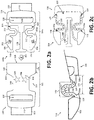
- Figure 2a illustrates a disconnected buckle assembly 100 with a male buckle component 104a according to a first example
- Figure 2b illustrates an enlarged view of the arm member 116 of the male buckle component 104a
- the buckle assembly 100 of Figures 2a and 2b is substantially the same as the buckle assembly 100 described in connection with Figures 1a and 1b , except for the male buckle component's 104a arm member 116, which is configured with an increased effective length 130, while preserving the same linear distance 142. That is, the effective length 130 is greater than the linear distance 142.
- the buttons 106 are provided as a solid, rigid button 106 coupled to the flexible lateral arms 112 at the distal ends 118 thereof.
- the buttons 106 are integrally connected to the flexible lateral arms 112.
- the flexible lateral arm 112 of the arm member 116 is non-linear and shaped to define one or more non-linear portions 202, which serve to increase the effective length 130.
- the non-linear portions 202 are arc-shaped (e.g., circular or partially circular).
- the non-linear portion 202 is arc-shaped and oriented inwardly toward the mating guide beam 138.
- each non-linear portion 202 may be adjusted to achieve a desired effective length 130. For example, to increase the effective length 130, additional or larger non-linear portions 202 may be provided. Conversely, the size of the non-linear portions 202 may be reduced to reduce the effective length 130.
- the size and shape of the non-linear portions 202 may be adjusted to accommodate aspects of the female buckle component 102.
- some buckle assemblies 100 may employ a female buckle component 102 with designs or features positioned on the housing 114 (e.g., in or on the plates 146).
- a user may require that the housing 114 be shaped (e.g., cut, die cut, molded, etc.) to define one or more cutouts 204, which may be a logo, shape, or other design.
- the flexible lateral arm 112 and non-linear portions 202 may be shaped such that they do not obstruct the cutouts 204 when viewed from above.
- cutouts 204 are illustrated as stars in Figure 2a .
- the flexible lateral arm 112 is shaped such that it would not block the star-shaped cutouts 204 when assembled.
- the rigid strut member 108 may be omitted and the lateral arm members 116 can be integrally connected to the main body 126 at another location.
- the lateral arm members 116 can be connected to the main body 126 at pivot point 124 as illustrated in Figure 2c .
- removing the rigid strut member 108 increases the effective length 130 compared to that of Figures 2a and 2b .
- the guide beam 138 can be secured to the button 106 (or another component of the buckle) via, for example, a flexible, resilient webbing 206.
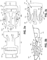
- Figure 3a illustrates a disconnected buckle assembly 100 with a male buckle component 104b according to a second example
- Figure 3b illustrates an enlarged view of the arm member 116 of the male buckle component 104b
- the buckle assembly 100 of Figures 3a and 3b is substantially the same as the buckle assembly 100 described in connection with Figures 1a and 1b , except for the male buckle component's 104b arm member 116, which is configured with an increased effective length 130, while preserving the same linear distance 142.
- the flexible lateral arm 112 of the arm member 116 is non-linear and shaped to define one or more non-linear portions 202 to increase the effective length 130.
- the flexible lateral arm 112 of the male buckle component 104b is shaped such that at least a portion of the lateral arm 112 extends beyond the distal end 118 thereof.
- the flexible lateral arm 112 itself defines the button 106 via one or more non-linear portions 202.
- the effective length 130 is further extended without affecting the linear distance 142.
- the design of Figures 3a and 3b allowed for a larger amount of hollow space (aka, negative space) between the mating guide beam 138 and each of the arm members 116 because the non-linear portions 202 need not extend inwardly as much to achieve an equivalent effective length 130.
- the non-linear portion 202 is configured to cause at least a portion 302 of the lateral arm 112 to overlap upon itself at an overlapping region 304.
- the overlapping region 304 can also serve as a button 106, yet is flexible.
- the flexible lateral arm 112 and non-linear portions 202 may be shaped such that they do not obstruct the cutouts 204.
- cutouts 204 are illustrated as lightning bolts in Figure 3a .
- the flexible lateral arm 112 is shaped such that it would not block the lightning bolt-shaped cutouts 204 when assembled.
- the rigid strut member 108 may be omitted and the lateral arm members 116 can be integrally connected to the main body 126 at another location.
- the lateral arm members 116 can be connected to the main body 126 at pivot point 124 as illustrated in Figure 3c .
- removing the rigid strut member 108 increases the effective length 130 compared to that of Figures 3a and 3b .
- the guide beam 138 can be secured to the button 106 (or another component of the buckle) via, for example, a flexible, resilient webbing 206.
- examples of the present disclosure provide a buckle assembly having mating components that may be easily disconnected.
- examples of the present disclosure provide a side-release buckle assembly in which a male buckle component may be disconnected from a female buckle component using less force as compared to conventional side-release buckle assemblies.
Landscapes
- Buckles (AREA)
- Automotive Seat Belt Assembly (AREA)
Abstract
Description
- The present application claims priority to
United States Provisional Patent Application No. 63/040,599, filed June 18, 2020 - The present disclosure generally relates to a buckle assembly, and more particularly to a side-release buckle assembly.
- A conventional side-release buckle assembly includes a male buckle component that is configured to mate with a female buckle component, such as shown and described in commonly-owned
U.S. Pat. No. 7,302,742 , entitled "Side-release Buckle Assembly," andU.S. Pat. No. 8,256,072 , entitled "Buckle." Each of the male buckle component and the female buckle component of the buckle is configured to retain a lead. The male buckle component includes integral buttons that may be engaged to release the male buckle component from the female buckle component, thereby disconnecting the buckle assembly. - The compression forces to release and assemble the buckle assembly are a function of the buckle's arm length. For example, a longer arm is more easily biased than a shorter arm. It is sometimes desirable to use arms that are more easily biased or flexed, they making it easier to release and assemble the buckle assembly. Increasing the buckle's arm length, however, traditionally increases the overall width of the buckle assembly, yet products often impose constraints on the overall width of the buckle assembly. It would therefore be highly desirable to provide a buckle assembly that is easier to release and assemble, while minimizing the overall width of the buckle assembly.
- The present disclosure relates generally to a buckle assembly, and more particularly to a side-release buckle assembly, substantially as illustrated by and described in connection with at least one of the figures, as set forth more completely in the claims.
- The foregoing and other objects, features, and advantages of the devices, systems, and methods described herein will be apparent from the following description of particular examples thereof, as illustrated in the accompanying figures; where like or similar reference numbers refer to like or similar structures. The figures are not necessarily to scale, emphasis instead being placed upon illustrating the principles of the devices, systems, and methods described herein.
-
Figures 1a and 1b illustrate, respectively, top plan views of disconnected and connected buckle assemblies in accordance with aspects of this disclosure. -
Figure 1c illustrates an enlarged view of the linear arm member of the buckle assembly ofFigures 1a and 1b . - Figure Id illustrates the male buckle component of
Figures 1a through 1c without a rigid strut member. -
Figure 2a illustrates a disconnected buckle assembly with a male buckle component in accordance with a first aspect of this disclosure. -
Figure 2b illustrates an enlarged view of the non-linear arm member of the male buckle component ofFigure 2a . -
Figure 2c illustrates the male buckle component ofFigures 2a and 2b without a rigid strut member. -
Figure 3a illustrates a disconnected buckle assembly with a male buckle component in accordance with a second aspect of this disclosure. -
Figure 3b illustrates an enlarged view of the non-linear arm member of the male buckle component ofFigure 3a . -
Figure 3c illustrates the male buckle component ofFigures 3a and 3b without a rigid strut member. - References to items in the singular should be understood to include items in the plural, and vice versa, unless explicitly stated otherwise or clear from the text. Grammatical conjunctions are intended to express any and all disjunctive and conjunctive combinations of conjoined clauses, sentences, words, and the like, unless otherwise stated or clear from the context. Recitation of ranges of values herein are not intended to be limiting, referring instead individually to any and all values falling within and/or including the range, unless otherwise indicated herein, and each separate value within such a range is incorporated into the specification as if it were individually recited herein. In the following description, it is understood that terms such as "first," "second," "top," "bottom," "side," "front," "back," and the like are words of convenience and are not to be construed as limiting terms. For example, while in some examples a first side is located adjacent or near a second side, the terms "first side" and "second side" do not imply any specific order in which the sides are ordered.
- The terms "about," "approximately," "substantially," or the like, when accompanying a numerical value, are to be construed as indicating a deviation as would be appreciated by one of ordinary skill in the art to operate satisfactorily for an intended purpose. Ranges of values and/or numeric values are provided herein as examples only, and do not constitute a limitation on the scope of the disclosure. The use of any and all examples, or exemplary language ("e.g.," "such as," or the like) provided herein, is intended merely to better illuminate the disclosed examples and does not pose a limitation on the scope of the disclosure. The terms "e.g.," and "for example" set off lists of one or more non-limiting examples, instances, or illustrations. No language in the specification should be construed as indicating any unclaimed element as essential to the practice of the disclosed examples.
- The term "and/or" means any one or more of the items in the list joined by "and/or." As an example, "x and/or y" means any element of the three-element set {(x), (y), (x, y)}. In other words, "x and/or y" means "one or both of x and y". As another example, "x, y, and/or z" means any element of the seven-element set {(x), (y), (z), (x, y), (x, z), (y, z), (x, y, z)}. In other words, "x, y, and/or z" means "one or more of x, y, and z."
- A buckle assembly can be used to join two or more components, such as a lead (e.g., straps, ropes, strips, cordage, or another material to be fastened). In one example, a male buckle component is configured to mate with a female buckle component into a securely connected position, where the male buckle component comprises: a main body; a mating guide beam; and one or more lateral arms coupled to the main body and configured to deflect about pivot points, each of said one or more lateral arms having a distal end configured to engage said female buckle component via a latching ledge of a button, wherein each of said one or more lateral arms is shaped to define an effective length between the latching ledge and the pivot point that is greater than a linear distance between the latching ledge and the pivot point.
- In some examples, the main body may comprise a rigid strut member, where the one or more lateral arms are coupled to the main body at the rigid strut member. The mating guide beam may extends outwardly from said rigid strut member. Each of said one or more lateral arms defines a non-linear portion. The non-linear portion may be configured to cause at least a portion of the lateral arm to extend beyond the distal end from the main body. For example at least a portion of the lateral arm overlaps upon itself. In some examples, each of said one or more lateral arms defines two non-linear portions. The male buckle component may further comprises a lead bar configured to secure a lead to the main body. The button may be configured to engage at least one button window formed in the female buckle component via a latching ledge when one or more lateral arms are inserted into the female buckle component. In some examples, the one or more lateral arms includes two lateral arms where the main body spring-biasing said two lateral arms apart from one another.
- In another example, a male buckle component configured to mate with a female buckle component into a securely connected position, where the male buckle component comprises: a main body; a mating guide beam; and one or more lateral arms coupled to the main body and configured to deflect about pivot points, each of said one or more lateral arms having a distal end configured to engage said female buckle component via a latching ledge of a button, wherein each of said one or more lateral arms is shaped to define an effective length between the latching ledge and the pivot point that is greater than a linear distance between the latching ledge and the pivot point, and wherein each of said one or more lateral arms defines a non-linear portion that is configured to cause at least a portion of the lateral arm to extend beyond the distal end. Each of said male buckle component and female buckle component may comprise a lead-receiving channel. The button may be configured to be engaged to disconnect said male buckle component from said female buckle component.
- In yet another example, a buckle assembly comprises: a female buckle component having a housing that defines a pocket and a button window; and a male buckle component having a main body, a mating guide beam, and one or more lateral arms coupled to the main body, wherein the button window is configured to engage a latching ledge of a button positioned at a distal end of at least one of the one or more lateral arms when inserted into the pocket, and wherein each of the one or more lateral arms is configured to deflect about a pivot point and is shaped to define an effective length between the latching ledge and the pivot point that is greater than a linear distance between the latching ledge and the pivot point. Each of the female buckle component and the male buckle component comprises a lead-receiving channel. The latching ledge may be configured to engage a lock ledge defined by the housing. The pivot point may be proximate a rigid strut member of the main body. The button may be configured to be engaged to disconnect said male buckle component from said female buckle component. The one or more lateral arms includes two lateral arms, said main body spring-biasing said two lateral arms apart from one another. Each of said one or more lateral arms defines a non-linear portion that may be configured to cause at least a portion of the lateral arm to extend beyond the distal end.
-
Figure 1a illustrates a top plan view of adisconnected buckle assembly 100, whileFigure 1b illustrates a top plan view of aconnected buckle assembly 100.Figure 1c illustrates an enlarged view of thearm member 116 of thebuckle assembly 100. As illustrated, thebuckle assembly 100 is configured as a side-release buckle assembly that includes amale buckle component 104 and afemale buckle component 102. In operation, the pair oflateral arm members 116 is inserted into and received by apocket 128 offemale buckle component 102 to latch thebuckle assembly 100. The pair oflateral arm members 116 is inserted via aninsertion force 154, which is indicated by Arrow B. Thebuckle assembly 100 is released or disconnected by providingcompression forces 152 inwardly from the side as indicated by Arrows A and A'. Themale buckle component 104 and thefemale buckle component 102 can be made as individual monolithic structures of plastic formed by injection molding processes, or the like. -
Leads 122 can be attached to each of themale buckle component 104 and thefemale buckle component 102 so thatbuckle assembly 100 can be used to secure together opposite ends of asingle lead 122 or to secure ends of separate leads 122. Example leads 122 include, inter alia, straps (e.g., backpack straps, belts, etc.), ropes, strips, cordage, or another material to be fastened. The leads 122 may be fabricated from, for example, plastic, nylon, leather, fabric, etc. In some examples, each of themale buckle component 104 and thefemale buckle component 102 may be adjustably positioned along the length of alead 122. Other structures or components, however, may be used to couple to themale buckle component 104 and/or thefemale buckle component 102 in addition to, or in lieu of, the leads 122. For example, themale buckle component 104 and/or thefemale buckle component 102 may be coupled to an item (e.g., bag, belt, garment, etc.) via mechanical fasteners (e.g., snaps, rivets, carabiner clips, etc.), adhesives, etc. - In order to securely mate the
male buckle component 104 into thefemale buckle component 102, themale buckle component 104 is urged into thefemale buckle component 102 viainsertion force 154. Thefemale buckle component 102 defines a receiving body orpocket 128. In some examples, thefemale buckle component 102 includes ahousing 114 formed as a set ofplates 146 spaced apart and secured at the edges via thesides 144 to form a pocket-like structure to define thepocket 128. Thesides 144 of thehousing 114 are shaped to define button windows 140 (e.g., openings in the sides 144). Thebutton windows 140 are sized and positioned to receivebuttons 106 when themale buckle component 104 is fully inserted into thepocket 128 of thefemale buckle component 102. Thepocket 128 may further define one or more channels to define a guide way to directmale buckle component 104 straight intofemale buckle component 102 from anentrance opening 150 to thepocket 128. The one or more channels may be form on, for example, in interior surface of the set ofplates 146. The one or more channels may be configured to guide themale buckle component 104 via amating guide beam 138 that outwardly extends from a rigid strut member. For example, usinginsertion force 154 as indicated by Arrow B, themating guide beam 138 passes into a mating channel or sleeve formed in the female buckle component in order to assure proper mating alignment. Once thebuttons 106 are snapably secured into thebutton windows 140 formed in thefemale buckle component 102, themale buckle component 104 is securely retained within thefemale buckle component 102. - The
housing 114 further includes one ormore lock ledges 148 to interface with themale buckle component 104. For example, an edge of eachbutton windows 140 nearest the entrance opening to thepocket 128 may define thelock ledge 148 or be provided another form of pediment. - The
male buckle component 104 includes a pair oflateral arm members 116. While the pair oflateral arm members 116 are illustrated as generally parallel one another, they may be non-parallel. Each of thelateral arm members 116 includes a flexiblelateral arm 112 with abutton 106 at adistal end 118 thereof. As illustrated, the flexiblelateral arms 112 are spaced apart and generally parallel to one another. In some examples, the flexiblelateral arm 112 and thebuttons 106 are fabricated as a unitary structure. In some examples, the flexiblelateral arm 112 and thebuttons 106 are distinct components. For example, thebuttons 106 may be a solid, rigid button coupled to an end of the flexiblelateral arm 112. In other examples, the flexiblelateral arm 112 may be configured to form a non-linear portion that defines, or otherwise serves as, thebutton 106. For example, the flexiblelateral arm 112 may be shaped to define thebutton 106. In either arrangement, thebuttons 106 define a latchingledge 106a configured to engage thefemale buckle component 102. For example, the latchingledge 106a may engage alock ledge 148 defined by thehousing 114 of thefemale buckle component 102. - When the
buckle assembly 100 is latched, as best illustrated inFigure 1b , the portion of thefemale buckle component 102 between thelock ledge 148 and theentrance opening 150 resides within the area of themale buckle component 104 between the latchingledge 106a and theshoulder 126a. To that end, thedistance 132 between the latchingledge 106a and theshoulder 126a of themain body 126 is dictated by thedistance 134 between thelock ledge 148 and the entrance opening 150 of thefemale buckle component 102. In some examples, thedistance 132 and thedistance 134 are about the same (e.g., within a 5% deviation) or thedistance 132 is slightly larger than the distance 134 (e.g., about 10% larger, as represented inFigure 1b ). - In some examples, a
rigid strut member 108 extends between thelateral arm members 116. Therigid strut member 108 is generally perpendicular to thelateral arm members 116. A lead-receivingchannel 120 is formed through themale buckle component 104 between, for example, therigid strut member 108 and alead bar 110. In some examples, therigid strut member 108 and thelead bar 110 are parallel to one another. The lead-receivingchannel 120 is configured to secure thelead 122. Thelateral arm members 116 are integrally connected to themain body 126 at pivot points 124 (e.g., via the rigid strut member 108). Thelateral arm members 116 are configured to pivot (e.g., flex) in the direction of arcs A and A' about pivot points 124 defined by the union of therigid strut member 108 and thelateral arm members 116. In other words, thelateral arm members 116 are rigidly coupled at pivot points 124 and configured to flex inwardly along its length (e.g., its effective length 130) in the direction of arcs A and A'. - In general, the
rigid strut member 108 is disposed between the pivot points 124 and adjacent the lead-receivingchannel 120. In one example, the pivot points 124 are proximate therigid strut member 108 of themain body 126. As such, the pivot points 124 are distally located from thelead bar 110 and therigid strut member 108. As shown inFigure 1a , therigid strut member 108 extends between thearm members 116 and is integrally connected with thelead bar 110 to form amain body 126 of themale buckle component 104. Thus, therigid strut member 108 is inflexible. While themain body 126 is illustrated with arigid strut member 108, therigid strut member 108 may be omitted and thelateral arm members 116 can be integrally connected to themain body 126 at another location. For example, thelateral arm members 116 can be connected at thelead bar 110. - In operation, the pair of
lateral arm members 116 is inserted into and received bypocket 128 offemale buckle component 102 as indicated by Arrow B to latch thebuckle assembly 100. In order to secure themale buckle component 104 into thefemale buckle component 102, themale buckle component 104 is urged into thefemale buckle component 102 in the direction of arrow B. Themating guide beam 138 of themale buckle component 104 moves into a reciprocal channel formed in thepocket 128 of thefemale buckle component 102 to ensure proper mating alignment between the female andmale buckle components - As the
male buckle component 104 is urged into thefemale buckle component 102, thelateral arm members 116 deflect inwardly (e.g., deformed or flexed) in the directions of arcs A and A' until thebuttons 106reach button openings 140 formed through thefemale buckle component 102. To that end, the flexiblelateral arm 112 is configured to flex along itseffective length 130 between thepivot point 124 and a latching ledge at itsdistal end 118. For purposes of this disclosure, theeffective length 130 refers to the length along the flexiblelateral arm 112 to enable the flexiblelateral arm 112 to flex between thepivot point 124 and the distalend latching ledge 106a during coupling and decoupling of thebuckle assembly 100. Theeffective length 130 is a function of the shape of the flexiblelateral arm 112. In the example ofFigures 1a through 1c , the flexiblelateral arm 112 are generally linear (e.g., straight) with a solid,rigid button 106 coupled at thedistal end 118 that defines the latchingledge 106a. As can be appreciated, in this case, theeffective length 130 of the flexiblelateral arm 112 is substantially equal to the linear distance 142 (e.g., a straight line distance) between thepivot point 124 and the latchingledge 106a. - When the
buttons 106 enter thebutton openings 140 in response to theinsertion force 154, the tension stored in the lateral arm members 116 (via the flexible lateral arm 112) biases thebuttons 106 laterally outward (e.g., in directions opposite that of arrows A and A') such that thebuttons 106 are secured within thebutton openings 140. At this point, themale buckle component 104 is secured to thefemale buckle component 102.Figure 1b illustrates a top plan view of thebuckle assembly 100 in which themale buckle component 104 is securely mated into thefemale buckle component 102. In order to disconnect themale buckle component 104 from thefemale buckle component 102, thebuttons 106 are squeezed inwardly (e.g., from the sides) toward one another in the direction of arcs A and A'. - Increasing the
effective length 130 of the flexiblelateral arm 112 decreases the amount ofcompression force 152 needed in directions A and A' to bias thelateral arm members 116, thereby making it easier to couple and decouple thebuckle assembly 100. For example,lower compression forces 152 results in alower insertion force 154. That is, a flexiblelateral arm 112 having a longereffective length 130 is more easily biased than shorter equivalents thereof and, therefore, requires alower compression force 152. - It is sometimes desirable to use
lateral arms 112 that are more easily biased, thus making it easier to release and assemble thebuckle assembly 100. When a linear flexiblelateral arm 112 is used, however, increasing theeffective length 130 increases thelinear distance 142 between thepivot point 124 and the latchingledge 106a, which results in alarger arm members 116 and, therefore, largermale buckle component 104. - Increasing the buckle's arm length traditionally increases the
overall width 136 of thebuckle assembly 100. In order to accommodate the largermale buckle component 104, thefemale buckle component 102 must likewise be larger (e.g., thedistance 134 between thelock ledge 148 and the entrance opening 150 must be increased to accommodate the longer flexible lateral arm 112), resulting in abuckle assembly 100 having a largeroverall width 136. Theoverall width 136 of thebuckle assembly 100 is dictated by the particular application and, for that reason, is not always a viable solution. That is, products often impose constraints on theoverall width 136 of thebuckle assembly 100. For example, whether for visual appearance or space limitations, thebuckle assembly 100 may be limited to a givenoverall width 136, while requiring alower compression force 152. - To increase the
effective length 130 of the flexiblelateral arm 112 without increasing thelinear distance 142, a non-linear flexiblelateral arm 112 may be employed. As will be described in the following examples, the non-linear flexiblelateral arm 112 includes one or more thenon-linear portions 202 that increase theeffective length 130 between thepivot point 124 and the latchingledge 106a, without affecting thelinear distance 142 between thepivot point 124 and the latchingledge 106a. In some examples, therigid strut member 108 may be omitted and thelateral arm members 116 can be integrally connected to themain body 126 at another location. For example, thelateral arm members 116 can be connected to themain body 126 atpivot point 124 as illustrated in Figure Id. In this example, removing therigid strut member 108 increases theeffective length 130 compared to that ofFigures 1a through 1c . -
Figure 2a illustrates adisconnected buckle assembly 100 with amale buckle component 104a according to a first example, whileFigure 2b illustrates an enlarged view of thearm member 116 of themale buckle component 104a. Thebuckle assembly 100 ofFigures 2a and 2b is substantially the same as thebuckle assembly 100 described in connection withFigures 1a and 1b , except for the male buckle component's104a arm member 116, which is configured with an increasedeffective length 130, while preserving the samelinear distance 142. That is, theeffective length 130 is greater than thelinear distance 142. In this example, thebuttons 106 are provided as a solid,rigid button 106 coupled to the flexiblelateral arms 112 at the distal ends 118 thereof. Thebuttons 106 are integrally connected to the flexiblelateral arms 112. - As illustrated, the flexible
lateral arm 112 of thearm member 116 is non-linear and shaped to define one or morenon-linear portions 202, which serve to increase theeffective length 130. By introducing one or morenon-linear portions 202, theeffective length 130 is increased without affecting thelinear distance 142. In some examples, thenon-linear portions 202 are arc-shaped (e.g., circular or partially circular). In the illustrated example, thenon-linear portion 202 is arc-shaped and oriented inwardly toward themating guide beam 138. - While the flexible
lateral arm 112 is illustrated with onenon-linear portion 202, additionalnon-linear portions 202 may be used depending on a desiredeffective length 130. Further, the size and shape of eachnon-linear portion 202 may be adjusted to achieve a desiredeffective length 130. For example, to increase theeffective length 130, additional or largernon-linear portions 202 may be provided. Conversely, the size of thenon-linear portions 202 may be reduced to reduce theeffective length 130. - In some examples, the size and shape of the
non-linear portions 202 may be adjusted to accommodate aspects of thefemale buckle component 102. For example, somebuckle assemblies 100 may employ afemale buckle component 102 with designs or features positioned on the housing 114 (e.g., in or on the plates 146). By way of illustration, a user may require that thehousing 114 be shaped (e.g., cut, die cut, molded, etc.) to define one ormore cutouts 204, which may be a logo, shape, or other design. In such cases, the flexiblelateral arm 112 andnon-linear portions 202 may be shaped such that they do not obstruct thecutouts 204 when viewed from above. For illustrative purposes,cutouts 204 are illustrated as stars inFigure 2a . In this example, the flexiblelateral arm 112 is shaped such that it would not block the star-shapedcutouts 204 when assembled. As noted above, in some examples, therigid strut member 108 may be omitted and thelateral arm members 116 can be integrally connected to themain body 126 at another location. For example, thelateral arm members 116 can be connected to themain body 126 atpivot point 124 as illustrated inFigure 2c . In this example, removing therigid strut member 108 increases theeffective length 130 compared to that ofFigures 2a and 2b . Theguide beam 138 can be secured to the button 106 (or another component of the buckle) via, for example, a flexible,resilient webbing 206. -
Figure 3a illustrates adisconnected buckle assembly 100 with amale buckle component 104b according to a second example, whileFigure 3b illustrates an enlarged view of thearm member 116 of themale buckle component 104b. Thebuckle assembly 100 ofFigures 3a and 3b is substantially the same as thebuckle assembly 100 described in connection withFigures 1a and 1b , except for the male buckle component's104b arm member 116, which is configured with an increasedeffective length 130, while preserving the samelinear distance 142. Like themale buckle component 104a ofFigures 2a and 2b , the flexiblelateral arm 112 of thearm member 116 is non-linear and shaped to define one or morenon-linear portions 202 to increase theeffective length 130. In this example, the flexiblelateral arm 112 of themale buckle component 104b is shaped such that at least a portion of thelateral arm 112 extends beyond thedistal end 118 thereof. Rather than employing a solid,rigid button 106 coupled at thedistal end 118, the flexiblelateral arm 112 itself defines thebutton 106 via one or morenon-linear portions 202. As a result, theeffective length 130 is further extended without affecting thelinear distance 142. Further, the design ofFigures 3a and 3b allowed for a larger amount of hollow space (aka, negative space) between themating guide beam 138 and each of thearm members 116 because thenon-linear portions 202 need not extend inwardly as much to achieve an equivalenteffective length 130. In the illustrated example, thenon-linear portion 202 is configured to cause at least aportion 302 of thelateral arm 112 to overlap upon itself at anoverlapping region 304. The overlappingregion 304 can also serve as abutton 106, yet is flexible. As noted above, the flexiblelateral arm 112 andnon-linear portions 202 may be shaped such that they do not obstruct thecutouts 204. For illustrative purposes,cutouts 204 are illustrated as lightning bolts inFigure 3a . In this example, the flexiblelateral arm 112 is shaped such that it would not block the lightning bolt-shapedcutouts 204 when assembled. As noted above, in some examples, therigid strut member 108 may be omitted and thelateral arm members 116 can be integrally connected to themain body 126 at another location. For example, thelateral arm members 116 can be connected to themain body 126 atpivot point 124 as illustrated inFigure 3c . In this example, removing therigid strut member 108 increases theeffective length 130 compared to that ofFigures 3a and 3b . Theguide beam 138 can be secured to the button 106 (or another component of the buckle) via, for example, a flexible,resilient webbing 206. - Various embodiments are described in the following numbered clauses:
- 1. A male buckle component configured to mate with a female buckle component into a securely connected position, said male buckle component comprising:
- a main body;
- a mating guide beam; and
- one or more lateral arms coupled to the main body and configured to deflect about pivot points, each of said one or more lateral arms having a distal end configured to engage said female buckle component via a latching ledge of a button,
wherein each of said one or more lateral arms is shaped to define an effective length between the latching ledge and the pivot point that is greater than a linear distance between the latching ledge and the pivot point.
- 2. The male buckle component of clause 1, wherein the main body comprises a rigid strut member, said one or more lateral arms being coupled to the main body at the rigid strut member.
- 3. The male buckle component of clause 2, wherein the mating guide beam extends outwardly from said rigid strut member.
- 4. The male buckle component of clause 1, wherein each of said one or more lateral arms defines a non-linear portion.
- 5. The male buckle component of clause 4, wherein the non-linear portion is configured to cause at least a portion of the lateral arm to extend beyond the distal end from the main body.
- 6. The male buckle component of clause 4, wherein at least a portion of the lateral arm overlaps upon itself.
- 7. The male buckle component of clause 1, wherein each of said one or more lateral arms defines two non-linear portions.
- 8. The male buckle component of clause 1, wherein said male buckle component further comprises a lead bar configured to secure a lead to the main body.
- 9. The male buckle component of clause 1, wherein the button is configured to engage at least one button window formed in the female buckle component via a latching ledge when one or more lateral arms are inserted into the female buckle component.
- 10. The male buckle component of clause 1, wherein the one or more lateral arms includes two lateral arms, said main body spring-biasing said two lateral arms apart from one another.
- 11. A male buckle component configured to mate with a female buckle component into a securely connected position, said male buckle component comprising:
- a main body;
- a mating guide beam; and
- one or more lateral arms coupled to the main body and configured to deflect about pivot points, each of said one or more lateral arms having a distal end configured to engage said female buckle component via a latching ledge of a button,
- wherein each of said one or more lateral arms is shaped to define an effective length between the latching ledge and the pivot point that is greater than a linear distance between the latching ledge and the pivot point, and
- wherein each of said one or more lateral arms defines a non-linear portion that is configured to cause at least a portion of the lateral arm to extend beyond the distal end.
- 12. The male buckle component of clause 11, wherein each of said male buckle component and female buckle component comprises a lead-receiving channel.
- 13. The male buckle component of clause 11, wherein said button is configured to be engaged to disconnect said male buckle component from said female buckle component.
- 14. A buckle assembly comprising:
- a female buckle component having a housing that defines a pocket and at least one button window; and
- a male buckle component having a main body, a mating guide beam, and one or more lateral arms coupled to the main body,
- wherein each button window is configured to engage a latching ledge of a button positioned at a distal end of at least one of the one or more lateral arms when inserted into the pocket, and
- wherein each of the one or more lateral arms is configured to deflect about a pivot point and is shaped to define an effective length between the latching ledge and the pivot point that is greater than a linear distance between the latching ledge and the pivot point.
- 15. The buckle assembly of clause 14, wherein each of the female buckle component and the male buckle component comprises a lead-receiving channel.
- 16. The buckle assembly of clause 14, wherein the latching ledge is configured to engage a lock ledge defined by the housing.
- 17. The buckle assembly of clause 14, wherein said pivot point is proximate a rigid strut member of the main body.
- 18. The buckle assembly of clause 14, wherein the button is configured to be engaged to disconnect said male buckle component from said female buckle component.
- 19. The buckle assembly of clause 14, wherein the one or more lateral arms includes two lateral arms, said main body spring-biasing said two lateral arms apart from one another.
- 20. The buckle assembly of clause 14, wherein each of said one or more lateral arms defines a non-linear portion that is configured to cause at least a portion of the lateral arm to extend beyond the distal end.
- Thus, examples of the present disclosure provide a buckle assembly having mating components that may be easily disconnected. In particular, examples of the present disclosure provide a side-release buckle assembly in which a male buckle component may be disconnected from a female buckle component using less force as compared to conventional side-release buckle assemblies.
- While the present method and/or system has been described with reference to certain implementations, it will be understood by those skilled in the art that various changes may be made and equivalents may be substituted without departing from the scope of the present method and/or system. In addition, many modifications may be made to adapt a particular situation or material to the teachings of the present disclosure without departing from its scope. For example, block and/or components of disclosed examples may be combined, divided, re-arranged, and/or otherwise modified. Therefore, the present method and/or system are not limited to the particular implementations disclosed. Instead, the present method and/or system will include all implementations falling within the scope of the appended claims, both literally and under the doctrine of equivalents.
Claims (15)
- A male buckle component configured to mate with a female buckle component into a securely connected position, said male buckle component comprising:a main body;a mating guide beam; andone or more lateral arms coupled to the main body and configured to deflect about pivot points, each of said one or more lateral arms having a distal end configured to engage said female buckle component via a latching ledge of a button,
wherein each of said one or more lateral arms is shaped to define an effective length between the latching ledge and the pivot point that is greater than a linear distance between the latching ledge and the pivot point. - The male buckle component of claim 1, wherein the main body comprises a rigid strut member, said one or more lateral arms being coupled to the main body at the rigid strut member, and optionally wherein the mating guide beam extends outwardly from said rigid strut member.
- The male buckle component of claim 1, wherein each of said one or more lateral arms defines a non-linear portion.
- The male buckle component of claim 3, wherein the non-linear portion is configured to cause at least a portion of the lateral arm to extend beyond the distal end from the main body, or wherein at least a portion of the lateral arm overlaps upon itself.
- The male buckle component of claim 1, wherein each of said one or more lateral arms defines two non-linear portions.
- The male buckle component of claim 1, wherein said male buckle component further comprises a lead bar configured to secure a lead to the main body.
- The male buckle component of claim 1, wherein the button is configured to engage at least one button window formed in the female buckle component via a latching ledge when one or more lateral arms are inserted into the female buckle component.
- A male buckle component configured to mate with a female buckle component into a securely connected position, said male buckle component comprising:a main body;a mating guide beam; andone or more lateral arms coupled to the main body and configured to deflect about pivot points, each of said one or more lateral arms having a distal end configured to engage said female buckle component via a latching ledge of a button,wherein each of said one or more lateral arms is shaped to define an effective length between the latching ledge and the pivot point that is greater than a linear distance between the latching ledge and the pivot point, andwherein each of said one or more lateral arms defines a non-linear portion that is configured to cause at least a portion of the lateral arm to extend beyond the distal end.
- A buckle assembly comprising:a female buckle component having a housing that defines a pocket and at least one button window; anda male buckle component having a main body, a mating guide beam, and one or more lateral arms coupled to the main body,wherein each button window is configured to engage a latching ledge of a button positioned at a distal end of at least one of the one or more lateral arms when inserted into the pocket, andwherein each of the one or more lateral arms is configured to deflect about a pivot point and is shaped to define an effective length between the latching ledge and the pivot point that is greater than a linear distance between the latching ledge and the pivot point.
- The male buckle component of claim 8, or the buckle assembly of claim 9, wherein each of the female buckle component and the male buckle component comprises a lead-receiving channel.
- The buckle assembly of claim 9, wherein the latching ledge is configured to engage a lock ledge defined by the housing.
- The buckle assembly of claim 9, wherein said pivot point is proximate a rigid strut member of the main body.
- The male buckle component of claim 8, or the buckle assembly of claim 9, wherein the button is configured to be engaged to disconnect said male buckle component from said female buckle component.
- The male buckle component of claim 1, or the buckle assembly of claim 9, wherein the one or more lateral arms includes two lateral arms, said main body spring-biasing said two lateral arms apart from one another.
- The buckle assembly of claim 9, wherein each of said one or more lateral arms defines a non-linear portion that is configured to cause at least a portion of the lateral arm to extend beyond the distal end.
Applications Claiming Priority (2)
| Application Number | Priority Date | Filing Date | Title |
|---|---|---|---|
| US202063040599P | 2020-06-18 | 2020-06-18 | |
| US17/333,260 US11533969B2 (en) | 2020-06-18 | 2021-05-28 | Side release buckle |
Publications (1)
| Publication Number | Publication Date |
|---|---|
| EP3925478A1 true EP3925478A1 (en) | 2021-12-22 |
Family
ID=76483103
Family Applications (1)
| Application Number | Title | Priority Date | Filing Date |
|---|---|---|---|
| EP21179512.5A Withdrawn EP3925478A1 (en) | 2020-06-18 | 2021-06-15 | Side release buckle |
Country Status (2)
| Country | Link |
|---|---|
| US (1) | US11533969B2 (en) |
| EP (1) | EP3925478A1 (en) |
Families Citing this family (2)
| Publication number | Priority date | Publication date | Assignee | Title |
|---|---|---|---|---|
| US11839270B1 (en) * | 2022-10-01 | 2023-12-12 | San Ragip Besbelli | Ring and wing buckle |
| USD1092193S1 (en) * | 2024-01-05 | 2025-09-09 | Chunxia Peng | Fastener |
Citations (6)
| Publication number | Priority date | Publication date | Assignee | Title |
|---|---|---|---|---|
| US4639982A (en) * | 1982-03-23 | 1987-02-03 | Nippon Notion Kogyo Co., Ltd. | Releasable buckle |
| EP1400183A2 (en) * | 2002-09-20 | 2004-03-24 | Ykk Corporation | Buckle |
| USD536279S1 (en) * | 2006-06-14 | 2007-02-06 | Illinois Tool Works Inc | Buckle member |
| US7302742B2 (en) | 2005-07-20 | 2007-12-04 | Illinois Tool Works Inc | Side-release buckle assembly |
| US20110219590A1 (en) * | 2010-03-15 | 2011-09-15 | Joseph Anscher | Quick release buckle assembly |
| US8256072B2 (en) | 2006-12-12 | 2012-09-04 | Illinois Tool Works Inc. | Buckle |
Family Cites Families (10)
| Publication number | Priority date | Publication date | Assignee | Title |
|---|---|---|---|---|
| JPS6129604U (en) * | 1984-07-27 | 1986-02-22 | 日本ノ−シヨン工業株式会社 | Batsukuru |
| US5027481A (en) * | 1990-11-01 | 1991-07-02 | Illinois Tool Works | Shell buckle |
| US5203058A (en) * | 1992-05-01 | 1993-04-20 | American Cord & Webbing Co., Inc. | Twin buckle for fastening straps and the like |
| US6226844B1 (en) | 1999-05-26 | 2001-05-08 | Velcro Industries B.V. | Quick release buckles |
| US6615460B1 (en) * | 2002-08-27 | 2003-09-09 | David Baumgarten | Optionally manual or automatic breakaway lanyard buckle |
| US7089633B2 (en) | 2004-09-15 | 2006-08-15 | Kim Ging Hui Enterprise Co., Ltd. | Side release buckle |
| US7140082B2 (en) | 2005-01-12 | 2006-11-28 | Button International Co., Ltd. | Side release buckle allowing locking from an angular position |
| CN102361569B (en) | 2009-03-31 | 2014-05-28 | Ykk株式会社 | Side buckle |
| DE112009005297B4 (en) | 2009-09-30 | 2013-12-05 | Ykk Corporation | Lateral releasable buckle |
| US8572820B2 (en) | 2010-05-21 | 2013-11-05 | Bae Systems Specialty Defense Systems Of Pennsylvania, Inc. | Dual release buckle |
-
2021
- 2021-05-28 US US17/333,260 patent/US11533969B2/en active Active
- 2021-06-15 EP EP21179512.5A patent/EP3925478A1/en not_active Withdrawn
Patent Citations (6)
| Publication number | Priority date | Publication date | Assignee | Title |
|---|---|---|---|---|
| US4639982A (en) * | 1982-03-23 | 1987-02-03 | Nippon Notion Kogyo Co., Ltd. | Releasable buckle |
| EP1400183A2 (en) * | 2002-09-20 | 2004-03-24 | Ykk Corporation | Buckle |
| US7302742B2 (en) | 2005-07-20 | 2007-12-04 | Illinois Tool Works Inc | Side-release buckle assembly |
| USD536279S1 (en) * | 2006-06-14 | 2007-02-06 | Illinois Tool Works Inc | Buckle member |
| US8256072B2 (en) | 2006-12-12 | 2012-09-04 | Illinois Tool Works Inc. | Buckle |
| US20110219590A1 (en) * | 2010-03-15 | 2011-09-15 | Joseph Anscher | Quick release buckle assembly |
Also Published As
| Publication number | Publication date |
|---|---|
| US20210392999A1 (en) | 2021-12-23 |
| US11533969B2 (en) | 2022-12-27 |
Similar Documents
| Publication | Publication Date | Title |
|---|---|---|
| US11786015B2 (en) | Safety release buckle | |
| US12220024B2 (en) | Buckle | |
| US8256072B2 (en) | Buckle | |
| US11533969B2 (en) | Side release buckle | |
| EP2780656B1 (en) | Garment assembly and release apparatus and method | |
| US20050125970A1 (en) | Buckle assembly | |
| US9220323B2 (en) | Slider provided with handle at rear for slide fastener | |
| CN112841818B (en) | Hasp | |
| US10316887B2 (en) | Locking connector assembly | |
| US8220117B2 (en) | Buckle structure | |
| US11771182B2 (en) | Belt buckle | |
| WO2010082972A1 (en) | Buckle | |
| US20160366989A1 (en) | System and assembly for securing a buckle housing to a component | |
| US20200022464A1 (en) | Anti-pinch buckle assembly | |
| CN100490708C (en) | Buckle and baby carrier using the same | |
| US20190037973A1 (en) | Buckle | |
| CA2438850C (en) | Seatbelt with child resistant buckle | |
| GB2339143A (en) | Connecting drawers to drawer slides | |
| EP1186251A1 (en) | Buckle | |
| AU2002244137A1 (en) | Seatbelt with child resistant buckle | |
| US12274332B2 (en) | Buckle | |
| US10334911B2 (en) | Buckle | |
| US6105219A (en) | Buckle guard | |
| EP0228754A1 (en) | Quick release threadless fastener | |
| WO2023137478A1 (en) | Quick-release latches |
Legal Events
| Date | Code | Title | Description |
|---|---|---|---|
| PUAI | Public reference made under article 153(3) epc to a published international application that has entered the european phase |
Free format text: ORIGINAL CODE: 0009012 |
|
| STAA | Information on the status of an ep patent application or granted ep patent |
Free format text: STATUS: THE APPLICATION HAS BEEN PUBLISHED |
|
| AK | Designated contracting states |
Kind code of ref document: A1 Designated state(s): AL AT BE BG CH CY CZ DE DK EE ES FI FR GB GR HR HU IE IS IT LI LT LU LV MC MK MT NL NO PL PT RO RS SE SI SK SM TR |
|
| B565 | Issuance of search results under rule 164(2) epc |
Effective date: 20211104 |
|
| STAA | Information on the status of an ep patent application or granted ep patent |
Free format text: STATUS: REQUEST FOR EXAMINATION WAS MADE |
|
| 17P | Request for examination filed |
Effective date: 20220511 |
|
| RBV | Designated contracting states (corrected) |
Designated state(s): AL AT BE BG CH CY CZ DE DK EE ES FI FR GB GR HR HU IE IS IT LI LT LU LV MC MK MT NL NO PL PT RO RS SE SI SK SM TR |
|
| STAA | Information on the status of an ep patent application or granted ep patent |
Free format text: STATUS: EXAMINATION IS IN PROGRESS |
|
| 17Q | First examination report despatched |
Effective date: 20230830 |
|
| STAA | Information on the status of an ep patent application or granted ep patent |
Free format text: STATUS: THE APPLICATION IS DEEMED TO BE WITHDRAWN |
|
| 18D | Application deemed to be withdrawn |
Effective date: 20240103 |