EP3923606A1 - Connection management method and apparatus, terminal and system - Google Patents
Connection management method and apparatus, terminal and system Download PDFInfo
- Publication number
- EP3923606A1 EP3923606A1 EP19915242.2A EP19915242A EP3923606A1 EP 3923606 A1 EP3923606 A1 EP 3923606A1 EP 19915242 A EP19915242 A EP 19915242A EP 3923606 A1 EP3923606 A1 EP 3923606A1
- Authority
- EP
- European Patent Office
- Prior art keywords
- terminal
- connection
- information
- response
- service
- Prior art date
- Legal status (The legal status is an assumption and is not a legal conclusion. Google has not performed a legal analysis and makes no representation as to the accuracy of the status listed.)
- Granted
Links
Images




Classifications
-
- H—ELECTRICITY
- H04—ELECTRIC COMMUNICATION TECHNIQUE
- H04W—WIRELESS COMMUNICATION NETWORKS
- H04W76/00—Connection management
- H04W76/10—Connection setup
- H04W76/14—Direct-mode setup
-
- H—ELECTRICITY
- H04—ELECTRIC COMMUNICATION TECHNIQUE
- H04W—WIRELESS COMMUNICATION NETWORKS
- H04W28/00—Network traffic management; Network resource management
- H04W28/02—Traffic management, e.g. flow control or congestion control
- H04W28/0215—Traffic management, e.g. flow control or congestion control based on user or device properties, e.g. MTC-capable devices
-
- H—ELECTRICITY
- H04—ELECTRIC COMMUNICATION TECHNIQUE
- H04W—WIRELESS COMMUNICATION NETWORKS
- H04W28/00—Network traffic management; Network resource management
- H04W28/02—Traffic management, e.g. flow control or congestion control
- H04W28/0252—Traffic management, e.g. flow control or congestion control per individual bearer or channel
-
- H—ELECTRICITY
- H04—ELECTRIC COMMUNICATION TECHNIQUE
- H04W—WIRELESS COMMUNICATION NETWORKS
- H04W4/00—Services specially adapted for wireless communication networks; Facilities therefor
- H04W4/30—Services specially adapted for particular environments, situations or purposes
- H04W4/40—Services specially adapted for particular environments, situations or purposes for vehicles, e.g. vehicle-to-pedestrians [V2P]
- H04W4/46—Services specially adapted for particular environments, situations or purposes for vehicles, e.g. vehicle-to-pedestrians [V2P] for vehicle-to-vehicle communication [V2V]
-
- H—ELECTRICITY
- H04—ELECTRIC COMMUNICATION TECHNIQUE
- H04W—WIRELESS COMMUNICATION NETWORKS
- H04W76/00—Connection management
- H04W76/10—Connection setup
- H04W76/11—Allocation or use of connection identifiers
-
- H—ELECTRICITY
- H04—ELECTRIC COMMUNICATION TECHNIQUE
- H04W—WIRELESS COMMUNICATION NETWORKS
- H04W76/00—Connection management
- H04W76/30—Connection release
Definitions
- the present application relates to the field of communications, in particular, to a connection management method and apparatus, a terminal and a system.
- V2X Vehicle to everything
- LTE-V2X Long Term Evolution-V2X
- NR-V2X New Radio-V2X
- Embodiments of the present application provide a connection management method and apparatus, a terminal and a system, which can solve the problem that a connection management mechanism applied to NR-V2X is not involved in the related art and the traditional terminal-based connection management mechanism cannot be directly used in NR-V2X.
- Technical solutions are as follows.
- an embodiment of the present application provides a method for connection management, including:
- an embodiment of the present application provides a method for connection management, including:
- an apparatus for connection management including:
- an apparatus for connection management including:
- an embodiment of the present application provides a terminal, including a processor, a memory, a transmitter and a receiver, the processor being configured to store one or more instructions indicated to be executed by the processor, and the processor being configured to control the transmitter and the receiver to execute the method for connection management of the first terminal side described in the above aspect.
- an embodiment of the present application provides a terminal, including a processor, a memory, a transmitter and a receiver, the processor being configured to store one or more instructions indicated to be executed by the processor, and the processor being configured to control the transmitter and the receiver to execute the method for connection management of the second terminal side described in the above aspect.
- an embodiment of the present application provides a V2X system, including: a first terminal and a second terminal, the first terminal includes the first terminal described in the above aspect; and the second terminal includes the second terminal described in the above aspect.
- an embodiment of the present application provides a computer-readable medium, storing one or more instructions, the instructions being used for implementing the methods for connection management described in the above aspects.
- module generally refers to a program or instructions stored in a memory capable of realizing some functions.
- unit generally refers to a functional structure divided with respect to logic, and the “unit” may be implemented by pure hardware or a combination of hardware and software.
- the “multiple” mentioned herein refers to two or more.
- the "and/or” describes an association relationship between associated objects, indicating that there may be three relationships, for example, A and/or B may indicate three situations: A alone, A and B, and B alone.
- the symbol “/” generally indicates that objects before and after the symbol "/" is in an "or” relationship.
- FIG.l is a schematic structure diagram of a V2X system provided according to an embodiment of the present application.
- the V2X system may be an NR-V2X system of 5G NR.
- the V2X system includes: a first terminal 120 and a second terminal 140.
- the first terminal 120 and the second terminal 140 are both automobile terminals, and as an automobile terminal has a fixed power input, they are always in a continuous receiving state.
- an automobile terminal is a vehicle machine (or on-board computer) installed on a vehicle.
- the first terminal 120 and the second terminal 140 directly communicate with each other using SideLink (SL) transmission technology, thus achieving higher spectrum efficiency and lower transmission delay.
- SL SideLink
- the transmission resources of the terminals are allocated by an access network device 160, and the first terminal 120 and the second terminal 140 send data on the side links of the allocated transmission resources.
- the access network device may allocate resources for single transmission to the terminals, and may also allocate resources for semi-static transmission to the terminals.
- the terminal selects from a pre-configured resource pool a transmission resource for data transmission, without the aid of the access network device for allocation.
- the method for connection management provided according to each embodiment of the present application is used in a scenario for managing a connection between the first terminal 120 and the second terminal 140; and the acts with the first terminal being an execution subject are executed by the first terminal 120 and the acts with the second terminal being an execution subject are executed by the second terminal 140.
- V2X system shown in FIG. 1 may include two or more terminals.
- first terminal 120 and the second terminal 140 are taken as examples for schematic illustration, which does not constitute a limitation on the present application.
- the network topology between terminals is a flat mesh structure
- a terminal may be either a sender of a unicast service or a receiver of another unicast service B, or may be either a central node (sending multicast messages) of a multicast service or a member node (receiving multicast messages) of another multicast service.
- sending multicast messages sending multicast messages
- member node receiving multicast messages
- FIG. 2 is a flow chart of a method for connection management provided according to an embodiment of the present invention. In this embodiment, description is made by taking the case as an example where the method for connection management is applied to the V2X system shown in FIG. 1 .
- the method includes acts 201-204.
- a first terminal sends first connection management information corresponding to a first service to a second terminal, the first connection management information being used for managing a connection between the first terminal and the second terminal, wherein different services correspond to different connection management information.
- connection setup, connection release, connection measurement, connection configuration and capability reporting is realized through the first connection management information.
- the second terminal receives the first connection management information corresponding to the first service sent by the first terminal.
- the second terminal sends first response information to the first terminal, the first response information being a response to the first connection management information.
- the first response information includes content corresponding to the content in the first connection management information, and may include at least one of a connection setup response, a connection release response, a connection measurement report, a connection configuration response and a capability report.
- the first terminal receives the first response information sent by the second terminal.
- the first terminal parses the first response information and determines, according to a parsing result, whether the connection meets a service requirement of the first service.
- an embodiment of the present application proposes a connection management mechanism for managing a connection between terminals based on a service, in the mechanism, the first terminal sends connection management information corresponding to the first service to the second terminal and receives a response of the second terminal to the connection management information, thus achieving the effect of managing the connection between terminals in the V2X system, and the mechanism can be adapted to the network topology between terminals in the V2X system.
- the acts with the first terminal being the execution subject may be independently implemented as a method for connection management of the first terminal side
- the acts with the second terminal being the execution subject may be independently implemented as a method for connection management of the second terminal side, which will not be described in further detail here in this embodiment.
- the connection management process between the first terminal and the second terminal is as shown in FIG. 3 , in which the first terminal serves as a control terminal for service A and service B, and the second terminal serves as a control terminal for service C and service D.
- the first terminal sends connection management information A of service A to the second terminal.
- the second terminal sends response information A to the connection management information A to the first terminal.
- the first terminal sends connection management information B of service B to the second terminal.
- the second terminal sends response information B to connection management information B to the first terminal.
- the second terminal sends connection management information C of service C to the first terminal.
- the first terminal sends response information C to connection management information C to the second terminal.
- the second terminal sends connection management information D of service D to the first terminal.
- the first terminal sends response information D to connection management information D to the second terminal.
- the first connection management information sent by the first terminal may include at least one of a service identifier of the first service, a first bearer identifier corresponding to the first service, and a first Quality of Service (QoS) flow identifier corresponding to the first service. Accordingly, the first terminal sends first connection management information for the first service to the second terminal according to the service identifier of the first service, the first bearer identifier or the first QoS flow identifier.
- QoS Quality of Service
- the first terminal may send the connection management information to the second terminal in at least one of the following ways:
- the first response information sent by the second terminal may also include at least one of a service identifier of the first service, a first bearer identifier corresponding to the first service and a first QoS flow identifier corresponding to the first service. Accordingly, the second terminal may send the response information to the first terminal in at least one of the following ways:
- the content included in the first connection management information is related to the functions implemented according to the first connection management information.
- the first connection management information may include at least one of first connection setup information, first connection release information, first connection measurement information, first connection configuration information and first capability reporting information.
- the first connection setup information is used for indicating to set up a connection corresponding to the first service.
- the first connection release information is used for indicating to release the connection corresponding to the first service.
- the first connection measurement information is used for indicating to measure the connection corresponding to the first service.
- the first connection configuration information includes at least one of a Service Data Adaptation Protocol (SDAP) protocol layer configuration, a Packet Data Convergence Protocol (PDCP) protocol layer configuration and a Radio Link Control (RLC) protocol layer configuration.
- SDAP Service Data Adaptation Protocol
- PDCP Packet Data Convergence Protocol
- RLC Radio Link Control
- the first capability reporting information is used for indicating the second terminal to report a first capability and/or a second capability, the first capability refers to an available capability of the second terminal for the first service, and the second capability includes at least one of an SDAP protocol layer capability, a PDCP protocol layer capability or an RLC protocol layer capability.
- the first response information sent by the second terminal may also include at least one of a first connection setup response, a first connection release response, a first connection measurement report, a first connection configuration response and a first capability report.
- the first connection setup response is a response when the connection corresponding to the first service is set up.
- the first connection release response is a response when the connection corresponding to the first service is released.
- the first connection measurement report refers to a measurement result of the connection corresponding to the first service.
- the first connection configuration response includes at least one of an SDAP protocol layer configuration, a PDCP protocol layer configuration and an RLC protocol layer configuration.
- the first capability report includes a first capability and/or a second capability, the first capability refers to an available capability of the second terminal for the first service, and the second capability includes at least one of an SDAP protocol layer capability, a PDCP protocol layer capability or a RLC protocol layer capability.
- connection management based on service A in FIG. 3
- process of performing connection management specifically includes the following acts 401-409.
- the first terminal sends a connection setup request (corresponding to the first connection setup information) to the second terminal.
- the second terminal sends a request response (request ACK) (success or failure, corresponding to the first connection setup response) to the first terminal.
- request ACK request response
- the first terminal sends a capability reporting request (capability request) (corresponding to the first capability reporting information) to the second terminal.
- the second terminal sends a capability report (corresponding to the first capability report) to the first terminal.
- the first terminal sends a connection configuration reporting request (configuration) (corresponding to the first connection configuration information and the first connection measurement information) to the second terminal.
- configuration corresponding to the first connection configuration information and the first connection measurement information
- connection configuration reporting request is used for requesting the second terminal to report at least one of a protocol layer parameter configuration (stack), a security parameter configuration (security) and a measurement configuration (measurement, meas).
- stack protocol layer parameter configuration
- security security parameter configuration
- measurement configuration measurement, meas
- the second terminal sends a connection configuration response (configuration report) (corresponding to the first connection configuration response) to the first terminal.
- connection configuration response includes a protocol layer parameter configuration and a security parameter configuration.
- the second terminal sends a measurement report (corresponding to the first connection measurement report) to the first terminal.
- the first terminal sends connection release information (release) to the second terminal.
- the second terminal makes a connection release response (release ACK).
- the first terminal sends the first connection management information according to the address, the bearer or the QoS flow corresponding to the configuration direction.
- the configuration direction is used for indicating the control terminal in the first terminal and the second terminal.
- the configuration direction is a first configuration direction
- the first terminal is a control terminal of the service
- the configuration direction is a second configuration direction
- the second terminal is a control terminal of the service.
- the first terminal may send the first connection management information corresponding to the first service to the second terminal in at least one of the following ways:
- the first connection management information includes at least one of a direction identifier of the configuration direction, a second bearer identifier corresponding to the configuration direction, and a second QoS flow identifier corresponding to the configuration direction.
- the second terminal may send the response information to the first terminal in at least one of the following ways:
- the first response information includes at least one of a direction identifier of the configuration direction, a second bearer identifier corresponding to the configuration direction, and a second QoS flow identifier corresponding to the configuration direction.
- connection management process between the first terminal and the second terminal is as shown in FIG. 5 .
- the first terminal serves as a control terminal for service A and service B
- the second terminal serves as a control terminal for service C and service D.
- the first terminal sends connection management information A and/or B to the second terminal.
- the connection management processes of service A and service B may not be distinguished.
- the second terminal sends response information A and/or B to the first terminal.
- the first terminal sends connection management information C and/or D to the second terminal.
- the processes of services C and D are distinguished from the processes of services A and B.
- the second terminal sends response information C and/or D to the first terminal.
- part of the connection configuration parameters are managed according to services, signaling overhead may be increased and even management cannot be performed according to a service, therefore, on the basis of the above embodiment, in a possible embodiment, part of the connection managements are performed based on services, while another part of the connection managements are performed based on link direction.
- connection management when connection management is performed based on links, the method further includes the following acts 205-208.
- the first terminal sends second connection management information corresponding to the second terminal to the second terminal, the second connection management information being used for managing the connection between the first terminal and the second terminal.
- the second connection management information sent by the first terminal includes at least one of a terminal identifier of the second terminal, a third bearer identifier corresponding to the second terminal and a third QoS flow identifier corresponding to the second terminal.
- third connection management information sent by the second terminal to the first terminal includes at least one of a terminal identifier of the first terminal, a bearer identifier corresponding to the first terminal and a QoS flow identifier corresponding to the first terminal.
- the first terminal may send the second connection management information to the second terminal in at least one of the following ways:
- the second terminal receives the second connection management information corresponding to the second terminal sent by the first terminal.
- the second terminal sends second response information to the first terminal, the second response information being a response to the second connection management information.
- the second response information sent by the second terminal includes at least one of a terminal identifier of the second terminal, a third bearer identifier corresponding to the second terminal and a third QoS flow identifier corresponding to the second terminal.
- the second terminal may send the second response information to the first terminal in at least one of the following ways:
- the first terminal receives the second response information sent by the second terminal, the second response information being a response to the second connection management information.
- the content in the second connection management information is directed to terminals (i.e., services are not distinguished).
- the second connection management information includes at least one of second connection setup information, second connection release information, second connection measurement information, second connection configuration information and second capability reporting information.
- the second connection setup information is used for indicating to set up the connection corresponding to the second terminal.
- the second connection release information is used for indicating to release the connection corresponding to the second terminal.
- the second connection measurement information is used for indicating to measure the connection corresponding to the second terminal.
- the second connection configuration information includes a network MAC layer configuration and/or a physical layer (PHY) layer configuration.
- PHY physical layer
- the second capability reporting information is used for indicating the second terminal to report a third capability and/or a fourth capability
- the third capability refers to a terminal available capability of the second terminal
- the fourth capability includes a MAC layer capability and/or a PHY layer capability.
- the second response information includes at least one of a second connection setup response, a second connection release response, a second connection measurement report, a second connection configuration response and a second capability report.
- the second connection setup response is a response when the connection corresponding to the second terminal is set up.
- the second connection release response is a response when the connection corresponding to the second terminal is released.
- the second connection measurement report refers to a measurement result of the connection corresponding to the second terminal.
- the second connection configuration response includes a MAC layer configuration and/or a PHY layer configuration.
- the second capability report includes a third capability and/or a fourth capability, the third capability refers to a terminal available capability of the second terminal, and the fourth capability includes a MAC layer capability and/or a PHY layer capability.
- the connection management process between the first terminal and the second terminal is as shown in FIG. 7 .
- the first terminal serves as a control terminal for service A and service B
- the second terminal serves as a control terminal for service C and service D.
- the first terminal sends first connection management information of service A to the second terminal.
- the second terminal sends first response information of service A to the first terminal.
- the first terminal sends second connection management information of the second terminal to the second terminal.
- the second terminal sends second response information of the second terminal to the first terminal.
- the first terminal sends first connection management information of service B to the second terminal.
- the second terminal sends first response information of service B to the first terminal.
- the second terminal sends first connection management information of service C to the first terminal.
- the first terminal sends first response information of service C to the second terminal.
- the second terminal sends second connection management information of the first terminal to the first terminal.
- the first terminal sends second response information of the first terminal to the second terminal.
- the second terminal sends first connection management information of service D to the first terminal.
- the first terminal sends first response information of service D to the second terminal.
- FIG. 8 is a schematic structure diagram of an apparatus for connection management provided according to an embodiment of the present application.
- the apparatus may be implemented as all or a part of the first terminal through software, hardware, or a combination of software and hardware.
- the apparatus includes a first sending unit 810 and a first receiving unit 820.
- the first sending unit 810 is configured to send first connection management information corresponding to a first service to a second terminal, the first connection management information being used for managing a connection between a first terminal and the second terminal, wherein different services correspond to different connection management information.
- the first receiving unit 820 is configured to receive first response information sent by the second terminal, the first response information being a response to the first connection management information.
- the first connection management information includes at least one of a service identifier of the first service, a first bearer identifier corresponding to the first service, and a first Quality of Service (QoS) flow identifier corresponding to the first service.
- QoS Quality of Service
- the first sending unit 810 is configured to implement at least one of the following functions:
- the first connection management information includes at least one of a direction identifier of a configuration direction, a second bearer identifier corresponding to the configuration direction and a second QoS flow identifier corresponding to the configuration direction, the configuration direction being used for indicating a control terminal in the first terminal and the second terminal.
- the first sending unit 810 is configured to implement at least one of the following functions:
- the first connection management information includes at least one of first connection setup information, first connection release information, first connection measurement information, first connection configuration information and first capability reporting information.
- the first connection setup information is used for indicating to set up a connection corresponding to the first service.
- the first connection release information is used for indicating to release the connection corresponding to the first service.
- the first connection measurement information is used for indicating to measure the connection corresponding to the first service.
- the first connection configuration information includes at least one of a Service Data Adaptation Protocol (SDAP) protocol layer configuration, a Packet Data Convergence Protocol (PDCP) protocol layer configuration, and a Radio Link Control (RLC) protocol layer configuration.
- SDAP Service Data Adaptation Protocol
- PDCP Packet Data Convergence Protocol
- RLC Radio Link Control
- the first capability reporting information is used for indicating the second terminal to report a first capability and/or a second capability, the first capability refers to an available capability of the second terminal for the first service, and the second capability includes at least one of an SDAP protocol layer capability, a PDCP protocol layer capability and an RLC protocol layer capability.
- the apparatus further includes a second sending unit and a second receiving unit.
- the second sending unit is configured to send second connection management information corresponding to the second terminal to the second terminal, the second connection management information being used for managing a connection between the first terminal and the second terminal.
- the second receiving unit is configured to receive second response information sent by the second terminal, the second response information being a response to the second connection management information.
- the second connection management information includes at least one of a terminal identifier of the second terminal, a third bearer identifier corresponding to the second terminal, and a third Quality of Service (QoS) flow identifier corresponding to the second terminal.
- QoS Quality of Service
- the second sending unit is configured to implement at least one of the following functions:
- the second connection management information includes at least one of second connection setup information, second connection release information, second connection measurement information, second connection configuration information, and second capability reporting information.
- the second connection setup information is used for indicating to set up a connection corresponding to the second terminal.
- the second connection release information is used for indicating to release the connection corresponding to the second terminal.
- the second connection measurement information is used for indicating to measure the connection corresponding to the second terminal.
- the second connection configuration information includes a network MAC layer configuration and/or a physical layer (PHY) layer configuration.
- PHY physical layer
- the second capability reporting information is used for indicating the second terminal to report a third capability and/or a fourth capability
- the third capability refers to a terminal available capability of the second terminal
- the fourth capability includes a MAC layer capability and/or a PHY layer capability.
- FIG. 9 is a schematic structure diagram of an apparatus for connection management provided according to an embodiment of the present application.
- the apparatus may be implemented as all or a part of the second terminal through software, hardware, or a combination of software and hardware.
- the apparatus includes a third receiving unit 910 and a third sending unit 920.
- the third receiving unit 910 is configured to receive first connection management information corresponding to a first service sent by a first terminal, the first connection management information being used for managing a connection between the first terminal and a second terminal, wherein different services correspond to different connection management information.
- the third sending unit 920 is configured to send first response information to the first terminal, the first response information being a response to the first connection management information.
- the first response information includes at least one of a service identifier of the first service, a first bearer identifier corresponding to the first service, and a first Quality of Service (QoS) flow identifier corresponding to the first service.
- QoS Quality of Service
- the third sending unit 920 is configured to implement at least one of the following functions:
- the first response information includes at least one of a direction identifier of a configuration direction, a second bearer identifier corresponding to the configuration direction, and a second QoS flow identifier corresponding to the configuration direction, the configuration direction being used for indicating a control terminal in the first terminal and the second terminal.
- the third sending unit 920 is configured to implement at least one of the following functions:
- the first response information includes at least one of a first connection setup response, a first connection release response, a first connection measurement report, a first connection configuration response, and a first capability report.
- the first connection setup response is a response when the connection corresponding to the first service is set up.
- the first connection release response is a response when the connection corresponding to the first service is released.
- the first connection measurement report refers to a measurement result of the connection corresponding to the first service.
- the first connection configuration response includes at least one of an SDAP protocol layer configuration, a PDCP protocol layer configuration and an RLC protocol layer configuration.
- the first capability report includes a first capability and/or a second capability, the first capability refers to an available capability of the second terminal for the first service, and the second capability includes at least one of an SDAP protocol layer capability, a PDCP protocol layer capability and an RLC protocol layer capability.
- the apparatus further includes a fourth receiving unit and a fourth sending unit.
- the fourth receiving unit is configured to receive second connection management information corresponding to the second terminal sent by the first terminal, the second connection management information being used for managing the connection between the first terminal and the second terminal.
- the fourth sending unit is configured to send second response information to the first terminal, the second response information being a response to the second connection management information.
- the second response information includes at least one of a terminal identifier of the second terminal, a third bearer identifier corresponding to the second terminal, and a third Quality of Service (QoS) flow identifier corresponding to the second terminal.
- QoS Quality of Service
- the fourth sending unit is configured to implement at least one of the following functions:
- the second response information includes at least one of a second connection setup response, a second connection release response, a second connection measurement report, a second connection configuration response and a second capability report.
- the second connection setup response is a response when a connection corresponding to the second terminal is set up.
- the second connection release response is a response when the connection corresponding to the second terminal is released.
- the second connection measurement report refers to a measurement result of the connection corresponding to the second terminal.
- the second connection configuration response includes a network MAC layer configuration and/or a physical layer (PHY) layer configuration.
- PHY physical layer
- the second capability report includes a third capability and/or a fourth capability, the third capability refers to a terminal available capability of the second terminal, and the fourth capability includes a MAC layer capability and/or a PHY layer capability.
- FIG. 10 is a schematic structure diagram of a terminal provided according to an example embodiment of the present application.
- the terminal may be implemented as a first terminal 120 or a second terminal 140.
- the terminal includes a processor 101, a receiver 102, a transmitter 103, a memory 104 and a bus 105.
- the processor 101 includes one or more processing cores.
- the processor 101 performs various functional applications and information processing by running software programs and modules.
- the receiver 102 and the transmitter 103 may be implemented as a communication component, which may be a communication chip.
- the memory 104 is connected to the processor 101 via the bus 105.
- the memory 104 may be used for storing at least one instruction, and the processor 101 is used for executing the at least one instruction to implement various acts executed by the first terminal or the second terminal in the above method embodiments.
- the memory 104 may be implemented by any type of transitory or non-transitory storage device or a combination thereof.
- the transitory or non-transitory storage device includes, but is not limited to, a magnetic disk or an optical disk, an electrically erasable programmable read only memory (EEPROM), an erasable programmable read only memory (EPROM), a static random access memory (SRAM), a read only memory (ROM), a magnetic memory, a flash memory and a programmable read only memory (PROM).
- the present application provides a computer-readable storage medium, storing at least one instruction which is loaded and executed by the processor to implement the method for connection management provided according to the above various method embodiments.
- the present application further provides a computer program product, which, when run on a terminal, causes the terminal to perform the method for connection management provided according to the above various method embodiments.
- the functions described in embodiments of the present invention may be implemented by using hardware, software, firmware or any combination thereof.
- these functions may be stored in a computer-readable medium or serve as one or more instructions or codes on the computer-readable medium for transmission.
- the computer-readable medium includes a computer storage medium and a communication medium.
- the communication medium includes any medium for transmitting computer programs from one place to another place conveniently, and the storage medium may be any available medium which can be accessed by a general-purpose computer or a special-purpose computer.
Landscapes
- Engineering & Computer Science (AREA)
- Computer Networks & Wireless Communication (AREA)
- Signal Processing (AREA)
- Mobile Radio Communication Systems (AREA)
Abstract
Description
- The present application relates to the field of communications, in particular, to a connection management method and apparatus, a terminal and a system.
- Vehicle to everything (V2X) is a communication network between vehicles, which can provide data communication with low-delay, high-reliability and security during high-speed movement of vehicles, and is widely used in the field of automatic driving, etc.
- In Long Term Evolution-V2X (LTE-V2X), since broadcast services are mainly focused, and there is no concept of connection between terminals, no connection management mechanism is defined in LTE-V2X. However, in New Radio-V2X (NR-V2X), since unicast and multicast services need to be considered, a corresponding connection management mechanism needs to be designed for terminals.
- Embodiments of the present application provide a connection management method and apparatus, a terminal and a system, which can solve the problem that a connection management mechanism applied to NR-V2X is not involved in the related art and the traditional terminal-based connection management mechanism cannot be directly used in NR-V2X. Technical solutions are as follows.
- In one aspect, an embodiment of the present application provides a method for connection management, including:
- sending, by a first terminal, first connection management information corresponding to a first service to a second terminal, the first connection management information being used for managing a connection between the first terminal and the second terminal, wherein different services correspond to different connection management information; and
- receiving, by the first terminal, first response information sent by the second terminal, the first response information being a response to the first connection management information.
- In another aspect, an embodiment of the present application provides a method for connection management, including:
- receiving, by a second terminal, first connection management information corresponding to a first service sent by a first terminal, the first connection management information being used for managing a connection between the first terminal and the second terminal, wherein different services correspond to different connection management information; and
- sending, by the second terminal, first response information to the first terminal, the first response information being a response to the first connection management information.
- In a further aspect, an embodiment of the present application provides an apparatus for connection management, including:
- a first sending unit, configured to send first connection management information corresponding to a first service to a second terminal, the first connection management information being used for managing a connection between a first terminal and the second terminal, wherein different services correspond to different connection management information; and
- a first receiving unit, configured to receive first response information sent by the second terminal, the first response information being a response to the first connection management information.
- In a further aspect, an embodiment of the present application provides an apparatus for connection management, including:
- a third receiving unit, configured to receive first connection management information corresponding to a first service sent by a first terminal, the first connection management information being used for managing a connection between the first terminal and a second terminal, wherein different services correspond to different connection management information; and
- a third sending unit, configured to send first response information to the first terminal, the first response information being a response to the first connection management information.
- In a further aspect, an embodiment of the present application provides a terminal, including a processor, a memory, a transmitter and a receiver, the processor being configured to store one or more instructions indicated to be executed by the processor, and the processor being configured to control the transmitter and the receiver to execute the method for connection management of the first terminal side described in the above aspect.
- In a further aspect, an embodiment of the present application provides a terminal, including a processor, a memory, a transmitter and a receiver, the processor being configured to store one or more instructions indicated to be executed by the processor, and the processor being configured to control the transmitter and the receiver to execute the method for connection management of the second terminal side described in the above aspect.
- In a further aspect, an embodiment of the present application provides a V2X system, including: a first terminal and a second terminal, the first terminal includes the first terminal described in the above aspect; and the second terminal includes the second terminal described in the above aspect.
- In a further aspect, an embodiment of the present application provides a computer-readable medium, storing one or more instructions, the instructions being used for implementing the methods for connection management described in the above aspects.
- In order to explain the technical solutions of embodiments of the present invention more clearly, drawings referred to in the description of the embodiments will be briefly introduced below. Obviously, the drawings in the following description are only some embodiments of the present invention. For those of ordinary skills in the art, other drawings may be obtained according to these drawings without paying an inventive effort.
-
FIG. 1 is a schematic structure diagram of a V2X system provided according to an embodiment of the present application. -
FIG. 2 is a flow chart of a method for connection management provided according to an embodiment of the present application. -
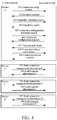
FIG. 3 is a schematic diagram of an implementation process of a method for connection management provided according to an example embodiment. -
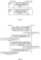
FIG. 4 is a schematic diagram of an implementation process of a method for connection management provided according to another example embodiment. -
FIG. 5 is a schematic diagram of an implementation process of a method for connection management provided according to a further example embodiment. -
FIG. 6 is a flow chart of a method for connection management provided according to another embodiment of the present application. -
FIG. 7 is a schematic diagram of an implementation process of a method for connection management provided according to a further example embodiment. -
FIG. 8 is a schematic structure diagram of an apparatus for connection management provided according to an embodiment of the present application. -
FIG. 9 is a schematic structure diagram of an apparatus for connection management provided according to an embodiment of the present application. -
FIG. 10 is a schematic structure diagram of a terminal provided according to an example embodiment of the present application. - In order to make objects, technical solutions and advantages of the present invention more clear, the embodiments of the present invention will be described in further detail below with reference to the accompanying drawings.
- The "module" mentioned herein generally refers to a program or instructions stored in a memory capable of realizing some functions. The "unit" mentioned herein generally refers to a functional structure divided with respect to logic, and the "unit" may be implemented by pure hardware or a combination of hardware and software.
- The "multiple" mentioned herein refers to two or more. The "and/or" describes an association relationship between associated objects, indicating that there may be three relationships, for example, A and/or B may indicate three situations: A alone, A and B, and B alone. The symbol "/" generally indicates that objects before and after the symbol "/" is in an "or" relationship.
- Referring to
FIG. 1 , FIG.l is a schematic structure diagram of a V2X system provided according to an embodiment of the present application. The V2X system may be an NR-V2X system of 5G NR. The V2X system includes: afirst terminal 120 and asecond terminal 140. - In a possible implementation, as shown in
FIG. 1 , thefirst terminal 120 and thesecond terminal 140 are both automobile terminals, and as an automobile terminal has a fixed power input, they are always in a continuous receiving state. For example, an automobile terminal is a vehicle machine (or on-board computer) installed on a vehicle. - Different from the conventional cellular system in which data communication is performed between terminals through an access network device (such as a base station), in the V2X system, the
first terminal 120 and thesecond terminal 140 directly communicate with each other using SideLink (SL) transmission technology, thus achieving higher spectrum efficiency and lower transmission delay. There are two modes for data transmission between thefirst terminal 120 and the second terminal. - In the first mode, as shown in
FIG. 1 , the transmission resources of the terminals are allocated by anaccess network device 160, and thefirst terminal 120 and thesecond terminal 140 send data on the side links of the allocated transmission resources. The access network device may allocate resources for single transmission to the terminals, and may also allocate resources for semi-static transmission to the terminals. - In the second mode, the terminal selects from a pre-configured resource pool a transmission resource for data transmission, without the aid of the access network device for allocation.
- The method for connection management provided according to each embodiment of the present application is used in a scenario for managing a connection between the
first terminal 120 and thesecond terminal 140; and the acts with the first terminal being an execution subject are executed by thefirst terminal 120 and the acts with the second terminal being an execution subject are executed by thesecond terminal 140. - It should be noted that the V2X system shown in
FIG. 1 may include two or more terminals. In this embodiment, only thefirst terminal 120 and thesecond terminal 140 are taken as examples for schematic illustration, which does not constitute a limitation on the present application. - In the V2X system, the network topology between terminals is a flat mesh structure, and a terminal may be either a sender of a unicast service or a receiver of another unicast service B, or may be either a central node (sending multicast messages) of a multicast service or a member node (receiving multicast messages) of another multicast service. This makes it difficult to determine, among the connected terminals, which terminal is a control terminal and which terminal is a controlled terminal. Further, since terminals are not distinguished as a control terminal and a controlled terminal in the traditional connection management mechanism, this mechanism can hardly be adopted in the V2X system.
- Referring to
FIG. 2, FIG. 2 is a flow chart of a method for connection management provided according to an embodiment of the present invention. In this embodiment, description is made by taking the case as an example where the method for connection management is applied to the V2X system shown inFIG. 1 . The method includes acts 201-204. - In act 201, a first terminal sends first connection management information corresponding to a first service to a second terminal, the first connection management information being used for managing a connection between the first terminal and the second terminal, wherein different services correspond to different connection management information.
- Optionally, at least one of connection setup, connection release, connection measurement, connection configuration and capability reporting is realized through the first connection management information.
- In act 202, the second terminal receives the first connection management information corresponding to the first service sent by the first terminal.
- In act 203, the second terminal sends first response information to the first terminal, the first response information being a response to the first connection management information.
- Optionally, the first response information includes content corresponding to the content in the first connection management information, and may include at least one of a connection setup response, a connection release response, a connection measurement report, a connection configuration response and a capability report.
- In act 204, the first terminal receives the first response information sent by the second terminal.
- Optionally, after receiving the first response information, the first terminal parses the first response information and determines, according to a parsing result, whether the connection meets a service requirement of the first service.
- To sum up, an embodiment of the present application proposes a connection management mechanism for managing a connection between terminals based on a service, in the mechanism, the first terminal sends connection management information corresponding to the first service to the second terminal and receives a response of the second terminal to the connection management information, thus achieving the effect of managing the connection between terminals in the V2X system, and the mechanism can be adapted to the network topology between terminals in the V2X system.
- It should be noted that, in the above embodiment, the acts with the first terminal being the execution subject may be independently implemented as a method for connection management of the first terminal side, and the acts with the second terminal being the execution subject may be independently implemented as a method for connection management of the second terminal side, which will not be described in further detail here in this embodiment.
- In a possible embodiment, when all connections between terminals are managed based on services, in an example, based on service A, service B, service C and service D, the connection management process between the first terminal and the second terminal is as shown in
FIG. 3 , in which the first terminal serves as a control terminal for service A and service B, and the second terminal serves as a control terminal for service C and service D. - In act 301, the first terminal sends connection management information A of service A to the second terminal.
- In act 302, the second terminal sends response information A to the connection management information A to the first terminal.
- In act 303, the first terminal sends connection management information B of service B to the second terminal.
- In act 304, the second terminal sends response information B to connection management information B to the first terminal.
- In act 305, the second terminal sends connection management information C of service C to the first terminal.
- In act 306, the first terminal sends response information C to connection management information C to the second terminal.
- In act 307, the second terminal sends connection management information D of service D to the first terminal.
- In act 308, the first terminal sends response information D to connection management information D to the second terminal.
- In a possible embodiment, the first connection management information sent by the first terminal may include at least one of a service identifier of the first service, a first bearer identifier corresponding to the first service, and a first Quality of Service (QoS) flow identifier corresponding to the first service. Accordingly, the first terminal sends first connection management information for the first service to the second terminal according to the service identifier of the first service, the first bearer identifier or the first QoS flow identifier.
- In a possible embodiment, the first terminal may send the connection management information to the second terminal in at least one of the following ways:
- 1. sending the first connection management information to the second terminal according to a target address corresponding to the first service;
- 2. sending the first connection management information to the second terminal according to a source address corresponding to the first service;
- 3. sending the first connection management information to the second terminal through a first bearer corresponding to the first service; and
- 4. sending the first connection management information to the second terminal through a first QoS flow corresponding to the first service.
- As a response to the first connection management information, the first response information sent by the second terminal may also include at least one of a service identifier of the first service, a first bearer identifier corresponding to the first service and a first QoS flow identifier corresponding to the first service. Accordingly, the second terminal may send the response information to the first terminal in at least one of the following ways:
- 1. sending the first response information to the first terminal according to a source address corresponding to the first service;
- 2. sending the first response information to the first terminal according to a target address corresponding to the first service;
- 3. sending the first response information to the first terminal through the first bearer corresponding to the first service; and
- 4. sending the first response information to the first terminal through the first QoS flow corresponding to the first service.
- In addition, the content included in the first connection management information is related to the functions implemented according to the first connection management information. In a possible embodiment, the first connection management information may include at least one of first connection setup information, first connection release information, first connection measurement information, first connection configuration information and first capability reporting information.
- The first connection setup information is used for indicating to set up a connection corresponding to the first service.
- The first connection release information is used for indicating to release the connection corresponding to the first service.
- The first connection measurement information is used for indicating to measure the connection corresponding to the first service. The first connection configuration information includes at least one of a Service Data Adaptation Protocol (SDAP) protocol layer configuration, a Packet Data Convergence Protocol (PDCP) protocol layer configuration and a Radio Link Control (RLC) protocol layer configuration.
- The first capability reporting information is used for indicating the second terminal to report a first capability and/or a second capability, the first capability refers to an available capability of the second terminal for the first service, and the second capability includes at least one of an SDAP protocol layer capability, a PDCP protocol layer capability or an RLC protocol layer capability.
- As a response to the first connection management information, the first response information sent by the second terminal may also include at least one of a first connection setup response, a first connection release response, a first connection measurement report, a first connection configuration response and a first capability report.
- The first connection setup response is a response when the connection corresponding to the first service is set up.
- The first connection release response is a response when the connection corresponding to the first service is released.
- The first connection measurement report refers to a measurement result of the connection corresponding to the first service.
- The first connection configuration response includes at least one of an SDAP protocol layer configuration, a PDCP protocol layer configuration and an RLC protocol layer configuration.
- The first capability report includes a first capability and/or a second capability, the first capability refers to an available capability of the second terminal for the first service, and the second capability includes at least one of an SDAP protocol layer capability, a PDCP protocol layer capability or a RLC protocol layer capability.
- For convenience of understanding, the case of performing connection management based on service A in
FIG. 3 is taken as an example, and as shown inFIG. 4 , the process of performing connection management specifically includes the following acts 401-409. - In act 401, the first terminal sends a connection setup request (corresponding to the first connection setup information) to the second terminal.
- In act 402, the second terminal sends a request response (request ACK) (success or failure, corresponding to the first connection setup response) to the first terminal.
- In act 403, the first terminal sends a capability reporting request (capability request) (corresponding to the first capability reporting information) to the second terminal.
- In act 404, the second terminal sends a capability report (corresponding to the first capability report) to the first terminal.
- In act 405, the first terminal sends a connection configuration reporting request (configuration) (corresponding to the first connection configuration information and the first connection measurement information) to the second terminal.
- The connection configuration reporting request is used for requesting the second terminal to report at least one of a protocol layer parameter configuration (stack), a security parameter configuration (security) and a measurement configuration (measurement, meas).
- In act 406, the second terminal sends a connection configuration response (configuration report) (corresponding to the first connection configuration response) to the first terminal.
- Optionally, the connection configuration response includes a protocol layer parameter configuration and a security parameter configuration.
- In act 407, the second terminal sends a measurement report (corresponding to the first connection measurement report) to the first terminal.
- In act 408, the first terminal sends connection release information (release) to the second terminal.
- In act 409, the second terminal makes a connection release response (release ACK).
- In order to further simplify the connection management process, in a possible embodiment, different services in the same configuration direction are not distinguished for a process, but processes in different configuration directions are distinguished (i.e., only the control terminals of the services are distinguished).
- Unlike the case in the above embodiment where the first connection management information is sent according to the address (the source address or the target address), the bearer or the QoS flow corresponding to the service, when the processes are distinguished based on the configuration direction, the first terminal sends the first connection management information according to the address, the bearer or the QoS flow corresponding to the configuration direction. The configuration direction is used for indicating the control terminal in the first terminal and the second terminal. When the configuration direction is a first configuration direction, the first terminal is a control terminal of the service, and when the configuration direction is a second configuration direction, the second terminal is a control terminal of the service.
- In a possible embodiment, the first terminal may send the first connection management information corresponding to the first service to the second terminal in at least one of the following ways:
- 1. sending the first connection management information to the second terminal according to a target address corresponding to a configuration direction;
- 2. sending the first connection management information to the second terminal according to a source address corresponding to the configuration direction;
- 3. sending the first connection management information to the second terminal through a second bearer corresponding to the configuration direction; and
- 4. sending the first connection management information to the second terminal through a second QoS flow corresponding to the configuration direction.
- Optionally, the first connection management information includes at least one of a direction identifier of the configuration direction, a second bearer identifier corresponding to the configuration direction, and a second QoS flow identifier corresponding to the configuration direction.
- Accordingly, the second terminal may send the response information to the first terminal in at least one of the following ways:
- 1. sending the first response information to the first terminal according to the source address corresponding to the configuration direction;
- 2. sending the first response information to the first terminal according to the target address corresponding to the configuration direction;
- 3. sending the first response information to the first terminal through the second bearer corresponding to the configuration direction; and
- 4. sending the first response information to the first terminal through the second QoS flow corresponding to the configuration direction.
- Optionally, the first response information includes at least one of a direction identifier of the configuration direction, a second bearer identifier corresponding to the configuration direction, and a second QoS flow identifier corresponding to the configuration direction.
- For the convenience of understanding, in an example, based on service A, service B, service C and service D, the connection management process between the first terminal and the second terminal is as shown in
FIG. 5 . The first terminal serves as a control terminal for service A and service B, and the second terminal serves as a control terminal for service C and service D. - In act 501, the first terminal sends connection management information A and/or B to the second terminal.
- Since the configuration directions of service A and service B are both the first configuration direction (the first terminal is the control terminal), the connection management processes of service A and service B may not be distinguished.
- In act 502, the second terminal sends response information A and/or B to the first terminal.
- In act 503, the first terminal sends connection management information C and/or D to the second terminal.
- Since the configuration directions of service C and service D are both the second configuration direction (the second terminal is the control terminal), which is different from the first configuration direction, the processes of services C and D are distinguished from the processes of services A and B.
- In act 504, the second terminal sends response information C and/or D to the first terminal.
- In addition, as to the contents contained in the first connection management information and the first response information in this embodiment, reference may be made to the embodiments of
FIGS. 3 and4 , which will not be described in further detail here in this embodiment. - If part of the connection configuration parameters are managed according to services, signaling overhead may be increased and even management cannot be performed according to a service, therefore, on the basis of the above embodiment, in a possible embodiment, part of the connection managements are performed based on services, while another part of the connection managements are performed based on link direction.
- On the basis of
FIG. 2 , as shown inFIG. 6 , when connection management is performed based on links, the method further includes the following acts 205-208. - In act 205, the first terminal sends second connection management information corresponding to the second terminal to the second terminal, the second connection management information being used for managing the connection between the first terminal and the second terminal.
- Different services are not distinguished for the second connection management information.
- Optionally, for a forward link from the first terminal to the second terminal, the second connection management information sent by the first terminal includes at least one of a terminal identifier of the second terminal, a third bearer identifier corresponding to the second terminal and a third QoS flow identifier corresponding to the second terminal.
- Accordingly, for a reverse link, third connection management information sent by the second terminal to the first terminal includes at least one of a terminal identifier of the first terminal, a bearer identifier corresponding to the first terminal and a QoS flow identifier corresponding to the first terminal.
- In a possible embodiment, the first terminal may send the second connection management information to the second terminal in at least one of the following ways:
- 1. sending the second connection management information to the second terminal according to a target address corresponding to the second terminal;
- 2. sending the second connection management information to the second terminal according to a source address corresponding to the second terminal;
- 3. sending the second connection management information to the second terminal through a third bearer corresponding to the second terminal; and
- 4. sending the second connection management information to the second terminal through a third QoS flow corresponding to the second terminal.
- In act 206, the second terminal receives the second connection management information corresponding to the second terminal sent by the first terminal.
- In act 207, the second terminal sends second response information to the first terminal, the second response information being a response to the second connection management information.
- Different services are not distinguished for the second response information.
- Optionally, the second response information sent by the second terminal includes at least one of a terminal identifier of the second terminal, a third bearer identifier corresponding to the second terminal and a third QoS flow identifier corresponding to the second terminal.
- In a possible embodiment, the second terminal may send the second response information to the first terminal in at least one of the following ways:
- 1. sending the second response information to the first terminal according to a source address corresponding to the second terminal;
- 2. sending the second response information to the first terminal according to a target address corresponding to the second terminal;
- 3. sending the second response information to the first terminal through a third bearer corresponding to the second terminal; and
- 4. sending the second response information to the first terminal through a third QoS flow corresponding to the second terminal.
- In act 208, the first terminal receives the second response information sent by the second terminal, the second response information being a response to the second connection management information.
- Different from the first connection management information (or the first response information) in which the content is directed to services, the content in the second connection management information (or the second response information) is directed to terminals (i.e., services are not distinguished).
- In a possible embodiment, the second connection management information includes at least one of second connection setup information, second connection release information, second connection measurement information, second connection configuration information and second capability reporting information.
- The second connection setup information is used for indicating to set up the connection corresponding to the second terminal.
- The second connection release information is used for indicating to release the connection corresponding to the second terminal.
- The second connection measurement information is used for indicating to measure the connection corresponding to the second terminal.
- The second connection configuration information includes a network MAC layer configuration and/or a physical layer (PHY) layer configuration.
- The second capability reporting information is used for indicating the second terminal to report a third capability and/or a fourth capability, the third capability refers to a terminal available capability of the second terminal, and the fourth capability includes a MAC layer capability and/or a PHY layer capability.
- Accordingly, the second response information includes at least one of a second connection setup response, a second connection release response, a second connection measurement report, a second connection configuration response and a second capability report.
- The second connection setup response is a response when the connection corresponding to the second terminal is set up.
- The second connection release response is a response when the connection corresponding to the second terminal is released.
- The second connection measurement report refers to a measurement result of the connection corresponding to the second terminal.
- The second connection configuration response includes a MAC layer configuration and/or a PHY layer configuration.
- The second capability report includes a third capability and/or a fourth capability, the third capability refers to a terminal available capability of the second terminal, and the fourth capability includes a MAC layer capability and/or a PHY layer capability.
- In an example, based on service A, service B, service C and service D, the connection management process between the first terminal and the second terminal is as shown in
FIG. 7 . The first terminal serves as a control terminal for service A and service B, and the second terminal serves as a control terminal for service C and service D. - In act 701, the first terminal sends first connection management information of service A to the second terminal.
- In act 702, the second terminal sends first response information of service A to the first terminal.
- In act 703, the first terminal sends second connection management information of the second terminal to the second terminal.
- In act 704, the second terminal sends second response information of the second terminal to the first terminal.
- In act 705, the first terminal sends first connection management information of service B to the second terminal.
- In
act 706, the second terminal sends first response information of service B to the first terminal. - In act 707, the second terminal sends first connection management information of service C to the first terminal.
- In act 708, the first terminal sends first response information of service C to the second terminal.
- In act 709, the second terminal sends second connection management information of the first terminal to the first terminal.
- In act 710, the first terminal sends second response information of the first terminal to the second terminal.
- In act 711, the second terminal sends first connection management information of service D to the first terminal.
- In act 712, the first terminal sends first response information of service D to the second terminal.
- The following is apparatus embodiments of the embodiments of the present application. As to the parts which are not described in details in the apparatus embodiments, reference may be made to the technical details disclosed in the above method embodiments.
- Referring to
FIG. 8, FIG. 8 is a schematic structure diagram of an apparatus for connection management provided according to an embodiment of the present application. The apparatus may be implemented as all or a part of the first terminal through software, hardware, or a combination of software and hardware. The apparatus includes afirst sending unit 810 and afirst receiving unit 820. - The
first sending unit 810 is configured to send first connection management information corresponding to a first service to a second terminal, the first connection management information being used for managing a connection between a first terminal and the second terminal, wherein different services correspond to different connection management information. - The
first receiving unit 820 is configured to receive first response information sent by the second terminal, the first response information being a response to the first connection management information. - Optionally, the first connection management information includes at least one of a service identifier of the first service, a first bearer identifier corresponding to the first service, and a first Quality of Service (QoS) flow identifier corresponding to the first service.
- Optionally, the first sending
unit 810 is configured to implement at least one of the following functions: - sending the first connection management information to the second terminal according to a target address corresponding to the first service;
- sending the first connection management information to the second terminal according to a source address corresponding to the first service;
- sending the first connection management information to the second terminal through a first bearer corresponding to the first service; and
- sending the first connection management information to the second terminal through a first QoS flow corresponding to the first service.
- Optionally, the first connection management information includes at least one of a direction identifier of a configuration direction, a second bearer identifier corresponding to the configuration direction and a second QoS flow identifier corresponding to the configuration direction, the configuration direction being used for indicating a control terminal in the first terminal and the second terminal.
- Optionally, the first sending
unit 810 is configured to implement at least one of the following functions: - sending the first connection management information to the second terminal according to a target address corresponding to a configuration direction;
- sending the first connection management information to the second terminal according to a source address corresponding to the configuration direction;
- sending the first connection management information to the second terminal through a second bearer corresponding to the configuration direction; and
- sending the first connection management information to the second terminal through a second QoS flow corresponding to the configuration direction.
- Optionally, the first connection management information includes at least one of first connection setup information, first connection release information, first connection measurement information, first connection configuration information and first capability reporting information.
- The first connection setup information is used for indicating to set up a connection corresponding to the first service.
- The first connection release information is used for indicating to release the connection corresponding to the first service.
- The first connection measurement information is used for indicating to measure the connection corresponding to the first service.
- The first connection configuration information includes at least one of a Service Data Adaptation Protocol (SDAP) protocol layer configuration, a Packet Data Convergence Protocol (PDCP) protocol layer configuration, and a Radio Link Control (RLC) protocol layer configuration.
- The first capability reporting information is used for indicating the second terminal to report a first capability and/or a second capability, the first capability refers to an available capability of the second terminal for the first service, and the second capability includes at least one of an SDAP protocol layer capability, a PDCP protocol layer capability and an RLC protocol layer capability.
- Optionally, the apparatus further includes a second sending unit and a second receiving unit.
- The second sending unit is configured to send second connection management information corresponding to the second terminal to the second terminal, the second connection management information being used for managing a connection between the first terminal and the second terminal.
- The second receiving unit is configured to receive second response information sent by the second terminal, the second response information being a response to the second connection management information.
- Optionally, different services are not distinguished for the second connection management information and the second response information.
- Optionally, the second connection management information includes at least one of a terminal identifier of the second terminal, a third bearer identifier corresponding to the second terminal, and a third Quality of Service (QoS) flow identifier corresponding to the second terminal.
- Optionally, the second sending unit is configured to implement at least one of the following functions:
- sending the second connection management information to the second terminal according to a target address corresponding to the second terminal;
- sending the second connection management information to the second terminal according to a source address corresponding to the second terminal;
- sending the second connection management information to the second terminal through a third bearer corresponding to the second terminal; and
- sending the second connection management information to the second terminal through a third QoS flow corresponding to the second terminal.
- Optionally, the second connection management information includes at least one of second connection setup information, second connection release information, second connection measurement information, second connection configuration information, and second capability reporting information.
- The second connection setup information is used for indicating to set up a connection corresponding to the second terminal.
- The second connection release information is used for indicating to release the connection corresponding to the second terminal.
- The second connection measurement information is used for indicating to measure the connection corresponding to the second terminal.
- The second connection configuration information includes a network MAC layer configuration and/or a physical layer (PHY) layer configuration.
- The second capability reporting information is used for indicating the second terminal to report a third capability and/or a fourth capability, the third capability refers to a terminal available capability of the second terminal, and the fourth capability includes a MAC layer capability and/or a PHY layer capability.
- Referring to
FIG. 9, FIG. 9 is a schematic structure diagram of an apparatus for connection management provided according to an embodiment of the present application. The apparatus may be implemented as all or a part of the second terminal through software, hardware, or a combination of software and hardware. The apparatus includes athird receiving unit 910 and athird sending unit 920. - The
third receiving unit 910 is configured to receive first connection management information corresponding to a first service sent by a first terminal, the first connection management information being used for managing a connection between the first terminal and a second terminal, wherein different services correspond to different connection management information. - The
third sending unit 920 is configured to send first response information to the first terminal, the first response information being a response to the first connection management information. - Optionally, the first response information includes at least one of a service identifier of the first service, a first bearer identifier corresponding to the first service, and a first Quality of Service (QoS) flow identifier corresponding to the first service.
- Optionally, the
third sending unit 920 is configured to implement at least one of the following functions: - sending the first response information to the first terminal according to a source address corresponding to the first service;
- sending the first response information to the first terminal according to a target address corresponding to the first service;
- sending the first response information to the first terminal through a first bearer corresponding to the first service; and
- sending the first response information to the first terminal through a first QoS flow corresponding to the first service.
- Optionally, the first response information includes at least one of a direction identifier of a configuration direction, a second bearer identifier corresponding to the configuration direction, and a second QoS flow identifier corresponding to the configuration direction, the configuration direction being used for indicating a control terminal in the first terminal and the second terminal.
- Optionally, the
third sending unit 920 is configured to implement at least one of the following functions: - sending the first response information to the first terminal according to a source address corresponding to the configuration direction;
- sending the first response information to the first terminal according to a target address corresponding to the configuration direction;
- sending the first response information to the first terminal through a second bearer corresponding to the configuration direction; and
- sending the first response information to the first terminal through a second QoS flow corresponding to the configuration direction.
- Optionally, the first response information includes at least one of a first connection setup response, a first connection release response, a first connection measurement report, a first connection configuration response, and a first capability report.
- The first connection setup response is a response when the connection corresponding to the first service is set up.
- The first connection release response is a response when the connection corresponding to the first service is released.
- The first connection measurement report refers to a measurement result of the connection corresponding to the first service.
- The first connection configuration response includes at least one of an SDAP protocol layer configuration, a PDCP protocol layer configuration and an RLC protocol layer configuration.
- The first capability report includes a first capability and/or a second capability, the first capability refers to an available capability of the second terminal for the first service, and the second capability includes at least one of an SDAP protocol layer capability, a PDCP protocol layer capability and an RLC protocol layer capability.
- Optionally, the apparatus further includes a fourth receiving unit and a fourth sending unit.
- The fourth receiving unit is configured to receive second connection management information corresponding to the second terminal sent by the first terminal, the second connection management information being used for managing the connection between the first terminal and the second terminal.
- The fourth sending unit is configured to send second response information to the first terminal, the second response information being a response to the second connection management information.
- Optionally, different services are not distinguished for the second connection management information and the second response information.
- Optionally, the second response information includes at least one of a terminal identifier of the second terminal, a third bearer identifier corresponding to the second terminal, and a third Quality of Service (QoS) flow identifier corresponding to the second terminal.
- Optionally, the fourth sending unit is configured to implement at least one of the following functions:
- sending the second response information to the first terminal according to a source address corresponding to the second terminal;
- sending the second response information to the first terminal according to a target address corresponding to the second terminal;
- sending the second response information to the first terminal through a third bearer corresponding to the second terminal; and
- sending the second response information to the first terminal through a third QoS flow corresponding to the second terminal.
- Optionally, the second response information includes at least one of a second connection setup response, a second connection release response, a second connection measurement report, a second connection configuration response and a second capability report.
- The second connection setup response is a response when a connection corresponding to the second terminal is set up.
- The second connection release response is a response when the connection corresponding to the second terminal is released.
- The second connection measurement report refers to a measurement result of the connection corresponding to the second terminal.
- The second connection configuration response includes a network MAC layer configuration and/or a physical layer (PHY) layer configuration.
- The second capability report includes a third capability and/or a fourth capability, the third capability refers to a terminal available capability of the second terminal, and the fourth capability includes a MAC layer capability and/or a PHY layer capability.
- Referring to
FIG. 10, FIG. 10 is a schematic structure diagram of a terminal provided according to an example embodiment of the present application. The terminal may be implemented as afirst terminal 120 or asecond terminal 140. The terminal includes aprocessor 101, areceiver 102, atransmitter 103, amemory 104 and abus 105. - The
processor 101 includes one or more processing cores. Theprocessor 101 performs various functional applications and information processing by running software programs and modules. - The
receiver 102 and thetransmitter 103 may be implemented as a communication component, which may be a communication chip. - The
memory 104 is connected to theprocessor 101 via thebus 105. - The
memory 104 may be used for storing at least one instruction, and theprocessor 101 is used for executing the at least one instruction to implement various acts executed by the first terminal or the second terminal in the above method embodiments. - In addition, the
memory 104 may be implemented by any type of transitory or non-transitory storage device or a combination thereof. The transitory or non-transitory storage device includes, but is not limited to, a magnetic disk or an optical disk, an electrically erasable programmable read only memory (EEPROM), an erasable programmable read only memory (EPROM), a static random access memory (SRAM), a read only memory (ROM), a magnetic memory, a flash memory and a programmable read only memory (PROM). - The present application provides a computer-readable storage medium, storing at least one instruction which is loaded and executed by the processor to implement the method for connection management provided according to the above various method embodiments.
- The present application further provides a computer program product, which, when run on a terminal, causes the terminal to perform the method for connection management provided according to the above various method embodiments.
- Those skilled in the art should realize that, in one or more examples described above, the functions described in embodiments of the present invention may be implemented by using hardware, software, firmware or any combination thereof. When implemented by software, these functions may be stored in a computer-readable medium or serve as one or more instructions or codes on the computer-readable medium for transmission. The computer-readable medium includes a computer storage medium and a communication medium. The communication medium includes any medium for transmitting computer programs from one place to another place conveniently, and the storage medium may be any available medium which can be accessed by a general-purpose computer or a special-purpose computer.
- The above descriptions are only preferred embodiments of the present invention and are not intended to limit the present invention. Any modification, equivalent substitution, improvement, etc. made within the spirit and principles of the present invention shall be included within the protection scope of the present invention.
Claims (47)
- A method for connection management, comprising:sending, by a first terminal, first connection management information corresponding to a first service to a second terminal, wherein the first connection management information is used for managing a connection between the first terminal and the second terminal, wherein different services correspond to different connection management information; andreceiving, by the first terminal, first response information sent by the second terminal, wherein the first response information is a response to the first connection management information.
- The method of claim 1, wherein the first connection management information comprises at least one of a service identifier of the first service, a first bearer identifier corresponding to the first service, and a first Quality of Service (QoS) flow identifier corresponding to the first service.
- The method of claim 1 or 2, wherein the first terminal sends the first connection management information corresponding to the first service to the second terminal in at least one of the following ways:sending, by the first terminal, the first connection management information to the second terminal according to a target address corresponding to the first service;sending, by the first terminal, the first connection management information to the second terminal according to a source address corresponding to the first service;sending, by the first terminal, the first connection management information to the second terminal through a first bearer corresponding to the first service; andsending, by the first terminal, the first connection management information to the second terminal through a first QoS flow corresponding to the first service.
- The method of claim 1, wherein the first connection management information comprises at least one of a direction identifier of a configuration direction, a second bearer identifier corresponding to the configuration direction, and a second QoS flow identifier corresponding to the configuration direction, the configuration direction is used for indicating a control terminal in the first terminal and the second terminal.
- The method of claim 1 or 4, wherein the first terminal sends the first connection management information corresponding to the first service to the second terminal in at least one of the following ways:sending, by the first terminal, the first connection management information to the second terminal according to a target address corresponding to a configuration direction;sending, by the first terminal, the first connection management information to the second terminal according to a source address corresponding to the configuration direction;sending, by the first terminal, the first connection management information to the second terminal through a second bearer corresponding to the configuration direction; andsending, by the first terminal, the first connection management information to the second terminal through a second QoS flow corresponding to the configuration direction.
- The method of any one of claims 2 to 5, wherein the first connection management information comprises at least one of first connection setup information, first connection release information, first connection measurement information, first connection configuration information, and first capability reporting information;the first connection setup information is used for indicating to set up a connection corresponding to the first service;the first connection release information is used for indicating to release the connection corresponding to the first service;the first connection measurement information is used for indicating to measure the connection corresponding to the first service;wherein the first connection configuration information comprises at least one of a Service Data Adaptation Protocol (SDAP) protocol layer configuration, a Packet Data Convergence Protocol (PDCP) protocol layer configuration, and a Radio Link Control (RLC) protocol layer configuration;the first capability reporting information is used for indicating the second terminal to report a first capability and/or a second capability, the first capability refers to an available capability of the second terminal for the first service, and the second capability comprises at least one of an SDAP protocol layer capability, a PDCP protocol layer capability, and an RLC protocol layer capability.
- The method of any one of claims 1 to 6, further comprising:sending, by the first terminal, second connection management information corresponding to the second terminal to the second terminal, wherein the second connection management information is used for managing the connection between the first terminal and the second terminal; andreceiving, by the first terminal, second response information sent by the second terminal, wherein the second response information is a response to the second connection management information.
- The method of claim 7, wherein different services are not distinguished for the second connection management information and the second response information.
- The method of claim 7, wherein the second connection management information comprises at least one of a terminal identifier of the second terminal, a third bearer identifier corresponding to the second terminal, and a third Quality of Service (QoS) flow identifier corresponding to the second terminal.
- The method of any one of claims 7 to 9, wherein the first terminal sends the second connection management information corresponding to the second terminal to the second terminal in at least one of the following ways:sending, by the first terminal, the second connection management information to the second terminal according to a target address corresponding to the second terminal;sending, by the first terminal, the second connection management information to the second terminal according to a source address corresponding to the second terminal;sending, by the first terminal, the second connection management information to the second terminal through a third bearer corresponding to the second terminal; andsending, by the first terminal, the second connection management information to the second terminal through a third QoS flow corresponding to the second terminal.
- The method of any one of claims 7 to 9, wherein the second connection management information comprises at least one of second connection setup information, second connection release information, second connection measurement information, second connection configuration information, and second capability reporting information;the second connection setup information is used for indicating to set up a connection corresponding to the second terminal;the second connection release information is used for indicating to release the connection corresponding to the second terminal;the second connection measurement information is used for indicating to measure the connection corresponding to the second terminal;the second connection configuration information comprises a network MAC layer configuration and/or a physical layer (PHY) layer configuration;the second capability reporting information is used for indicating the second terminal to report a third capability and/or a fourth capability, the third capability refers to a terminal available capability of the second terminal, and the fourth capability comprises a MAC layer capability and/or a PHY layer capability.
- A method for connection management, comprising:receiving, by a second terminal, first connection management information corresponding to a first service sent by a first terminal, wherein the first connection management information is used for managing a connection between the first terminal and the second terminal, wherein different services correspond to different connection management information; andsending, by the second terminal, first response information to the first terminal, wherein the first response information is a response to the first connection management information.
- The method of claim 12, wherein the first response information comprises at least one of a service identifier of the first service, a first bearer identifier corresponding to the first service, and a first Quality of Service (QoS) flow identifier corresponding to the first service.
- The method of claim 12 or 13, wherein the second terminal receives the first connection management information corresponding to the first service sent by the first terminal in at least one of the following ways:sending, by the second terminal, the first response information to the first terminal according to a source address corresponding to the first service;sending, by the second terminal, the first response information to the first terminal according to a target address corresponding to the first service;sending, by the second terminal, the first response information to the first terminal through a first bearer corresponding to the first service; andsending, by the second terminal, the first response information to the first terminal through a first QoS flow corresponding to the first service.
- The method of claim 12, wherein the first response information comprises at least one of a direction identifier of a configuration direction, a second bearer identifier corresponding to the configuration direction, and a second QoS flow identifier corresponding to the configuration direction, the configuration direction is used for indicating a control terminal in the first terminal and the second terminal.
- The method of claim 12 or 15, wherein the second terminal receives the first connection management information corresponding to the first service sent by the first terminal in at least one of the following ways:sending, by the second terminal, the first response information to the first terminal according to a source address corresponding to a configuration direction;sending, by the second terminal, the first response information to the first terminal according to a target address corresponding to the configuration direction;sending, by the second terminal, the first response information to the first terminal through a second bearer corresponding to the configuration direction; andsending, by the second terminal, the first response information to the first terminal through a second QoS flow corresponding to the configuration direction.
- The method of any one of claims 13 to 16, wherein the first response information comprises at least one of a first connection setup response, a first connection release response, a first connection measurement report, a first connection configuration response, and a first capability report;the first connection setup response is a response when a connection corresponding to the first service is set up;the first connection release response is a response when the connection corresponding to the first service is released;the first connection measurement report refers to a measurement result of the connection corresponding to the first service;the first connection configuration response comprises at least one of an SDAP protocol layer configuration, a PDCP protocol layer configuration and an RLC protocol layer configuration;the first capability report comprises a first capability and/or a second capability, the first capability refers to an available capability of the second terminal for the first service, and the second capability comprises at least one of an SDAP protocol layer capability, a PDCP protocol layer capability, and an RLC protocol layer capability.
- The method of any one of claims 12 to 17, further comprising:receiving, by the second terminal, second connection management information corresponding to the second terminal sent by the first terminal, wherein the second connection management information is used for managing the connection between the first terminal and the second terminal; andsending, by the second terminal, second response information to the first terminal, wherein the second response information is a response to the second connection management information.
- The method of claim 18, wherein different services are not distinguished for the second connection management information and the second response information.
- The method of claim 18, wherein the second response information comprises at least one of a terminal identifier of the second terminal, a third bearer identifier corresponding to the second terminal, and a third Quality of Service (QoS) flow identifier corresponding to the second terminal.
- The method of any one of claims 18 to 20, wherein the second terminal sends the second response information to the first terminal in at least one of the following ways:sending, by the second terminal, the second response information to the first terminal according to a source address corresponding to the second terminal;sending, by the second terminal, the second response information to the first terminal according to a target address corresponding to the second terminal;sending, by the second terminal, the second response information to the first terminal through a third bearer corresponding to the second terminal; andsending, by the second terminal, the second response information to the first terminal through a third QoS flow corresponding to the second terminal.
- The method of claims 18 to 20, wherein the second response information comprises at least one of a second connection setup response, a second connection release response, a second connection measurement report, a second connection configuration response, and a second capability report;the second connection setup response is a response when a connection corresponding to the second terminal is set up;the second connection release response is a response when the connection corresponding to the second terminal is released;the second connection measurement report refers to a measurement result of the connection corresponding to the second terminal;the second connection configuration response comprises a network MAC layer configuration and/or a physical layer (PHY) layer configuration;the second capability report comprises a third capability and/or a fourth capability, the third capability refers to a terminal available capability of the second terminal, and the fourth capability comprises a MAC layer capability and/or a PHY layer capability.
- An apparatus for connection management, comprising:a first sending unit, configured to send first connection management information corresponding to a first service to a second terminal, wherein the first connection management information is used for managing a connection between a first terminal and the second terminal, wherein different services correspond to different connection management information; anda first receiving unit, configured to receive first response information sent by the second terminal, wherein the first response information is a response to the first connection management information.
- The apparatus of claim 23, wherein the first connection management information comprises at least one of a service identifier of the first service, a first bearer identifier corresponding to the first service, and a first Quality of Service (QoS) flow identifier corresponding to the first service.
- The apparatus of claim 23 or 24, wherein the first sending unit is configured to implement at least one of the following functions:sending the first connection management information to the second terminal according to a target address corresponding to the first service;sending the first connection management information to the second terminal according to a source address corresponding to the first service;sending the first connection management information to the second terminal through a first bearer corresponding to the first service; andsending the first connection management information to the second terminal through a first QoS flow corresponding to the first service.
- The apparatus of claim 23, wherein the first connection management information comprises at least one of a direction identifier of a configuration direction, a second bearer identifier corresponding to the configuration direction, and a second QoS flow identifier corresponding to the configuration direction, the configuration direction is used for indicating a control terminal in the first terminal and the second terminal.
- The apparatus of claim 23 or 26, wherein the first sending unit is configured to implement at least one of the following functions:sending the first connection management information to the second terminal according to a target address corresponding to a configuration direction;sending the first connection management information to the second terminal according to a source address corresponding to the configuration direction;sending the first connection management information to the second terminal through a second bearer corresponding to the configuration direction; andsending the first connection management information to the second terminal through a second QoS flow corresponding to the configuration direction.
- The apparatus of any one of claims 24 to 27, wherein the first connection management information comprises at least one of first connection setup information, first connection release information, first connection measurement information, first connection configuration information and first capability reporting information;the first connection setup information is used for indicating to set up a connection corresponding to the first service;the first connection release information is used for indicating to release the connection corresponding to the first service;the first connection measurement information is used for indicating to measure the connection corresponding to the first service;the first connection configuration information comprises at least one of a Service Data Adaptation Protocol (SDAP) protocol layer configuration, a Packet Data Convergence Protocol (PDCP) protocol layer configuration, and a Radio Link Control (RLC) protocol layer configuration;the first capability reporting information is used for indicating the second terminal to report a first capability and/or a second capability, the first capability refers to an available capability of the second terminal for the first service, and the second capability comprises at least one of an SDAP protocol layer capability, a PDCP protocol layer capability and an RLC protocol layer capability.
- The apparatus of any one of claims 23 to 28, further comprising:a second sending unit configured to send second connection management information corresponding to the second terminal to the second terminal, wherein the second connection management information is used for managing a connection between the first terminal and the second terminal; anda second receiving unit configured to receive second response information sent by the second terminal, wherein the second response information is a response to the second connection management information.
- The apparatus of claim 29, wherein different services are not distinguished for the second connection management information and the second response information.
- The apparatus of claim 29, wherein the second connection management information comprises at least one of a terminal identifier of the second terminal, a third bearer identifier corresponding to the second terminal, and a third Quality of Service (QoS) flow identifier corresponding to the second terminal.
- The apparatus of any one of claims 29 to 31, wherein the second sending unit is configured to implement at least one of the following functions:sending the second connection management information to the second terminal according to a target address corresponding to the second terminal;sending the second connection management information to the second terminal according to a source address corresponding to the second terminal;sending the second connection management information to the second terminal through a third bearer corresponding to the second terminal; andsending the second connection management information to the second terminal through a third QoS flow corresponding to the second terminal.
- The apparatus of any one of claims 29 to 31, wherein the second connection management information comprises at least one of second connection setup information, second connection release information, second connection measurement information, second connection configuration information, and second capability reporting information;the second connection setup information is used for indicating to set up a connection corresponding to the second terminal;the second connection release information is used for indicating to release the connection corresponding to the second terminal;the second connection measurement information is used for indicating to measure the connection corresponding to the second terminal;the second connection configuration information comprises a network MAC layer configuration and/or a physical layer (PHY) layer configuration;the second capability reporting information is used for indicating the second terminal to report a third capability and/or a fourth capability, the third capability refers to a terminal available capability of the second terminal, and the fourth capability comprises a MAC layer capability and/or a PHY layer capability.
- An apparatus for connection management, comprising:a third receiving unit, configured to receive first connection management information corresponding to a first service sent by a first terminal, wherein the first connection management information is used for managing a connection between the first terminal and a second terminal, wherein different services correspond to different connection management information; anda third sending unit, configured to send first response information to the first terminal, wherein the first response information is a response to the first connection management information.
- The apparatus of claim 34, wherein the first response information comprises at least one of a service identifier of the first service, a first bearer identifier corresponding to the first service, and a first Quality of Service (QoS) flow identifier corresponding to the first service.
- The apparatus of claim 34 or 35, wherein the third sending unit is configured to implement at least one of the following functions:sending the first response information to the first terminal according to a source address corresponding to the first service;sending the first response information to the first terminal according to a target address corresponding to the first service;sending the first response information to the first terminal through a first bearer corresponding to the first service; andsending the first response information to the first terminal through a first QoS flow corresponding to the first service.
- The apparatus of claim 34, wherein the first response information comprises at least one of a direction identifier of a configuration direction, a second bearer identifier corresponding to the configuration direction, and a second QoS flow identifier corresponding to the configuration direction, the configuration direction is used for indicating a control terminal in the first terminal and the second terminal.
- The apparatus of claim 34 or 37, wherein the third sending unit is configured to implement at least one of the following functions:sending the first response information to the first terminal according to a source address corresponding to a configuration direction;sending the first response information to the first terminal according to a target address corresponding to the configuration direction;sending the first response information to the first terminal through a second bearer corresponding to the configuration direction; andsending the first response information to the first terminal through a second QoS flow corresponding to the configuration direction.
- The apparatus of any one of claims 35 to 38, wherein the first response information comprises at least one of a first connection setup response, a first connection release response, a first connection measurement report, a first connection configuration response, and a first capability report;the first connection setup response is a response when a connection corresponding to the first service is set up;the first connection release response is a response when the connection corresponding to the first service is released;the first connection measurement report refers to a measurement result of the connection corresponding to the first service;the first connection configuration response comprises at least one of an SDAP protocol layer configuration, a PDCP protocol layer configuration and an RLC protocol layer configuration;the first capability report comprises a first capability and/or a second capability, the first capability refers to an available capability of the second terminal for the first service, and the second capability comprises at least one of an SDAP protocol layer capability, a PDCP protocol layer capability, and an RLC protocol layer capability.
- The apparatus of any one of claims 34 to 39, further comprising:a fourth receiving unit configured to receive second connection management information corresponding to the second terminal sent by the first terminal, wherein the second connection management information is used for managing the connection between the first terminal and the second terminal; anda fourth sending unit configured to send second response information to the first terminal, wherein the second response information is a response to the second connection management information.
- The apparatus of claim 40, wherein different services are not distinguished for the second connection management information and the second response information.
- The apparatus of claim 40, wherein the second response information comprises at least one of a terminal identifier of the second terminal, a third bearer identifier corresponding to the second terminal, and a third Quality of Service (QoS) flow identifier corresponding to the second terminal.
- The apparatus of any one of claims 40 to 42, wherein the fourth sending unit is configured to implement at least one of the following functions:sending the second response information to the first terminal according to a source address corresponding to the second terminal;sending the second response information to the first terminal according to a target address corresponding to the second terminal;sending the second response information to the first terminal through a third bearer corresponding to the second terminal; andsending the second response information to the first terminal through a third QoS flow corresponding to the second terminal.
- The apparatus of claims 40 to 42, wherein the second response information comprises at least one of a second connection setup response, a second connection release response, a second connection measurement report, a second connection configuration response and a second capability report;the second connection setup response is a response when a connection corresponding to the second terminal is set up;the second connection release response is a response when the connection corresponding to the second terminal is released;the second connection measurement report refers to a measurement result of the connection corresponding to the second terminal;the second connection configuration response comprises a network MAC layer configuration and/or a physical layer (PHY) layer configuration;the second capability report comprises a third capability and/or a fourth capability, the third capability refers to a terminal available capability of the second terminal, and the fourth capability comprises a MAC layer capability and/or a PHY layer capability.
- A terminal, wherein the terminal comprises a processor, a memory, a transmitter and a receiver, the processor is configured to store one or more instructions indicated to be executed by the processor, and the processor is configured to control the transmitter and the receiver to execute the method for connection management of any one of claims 1 to 11.
- A terminal, wherein the terminal comprises a processor, a memory, a transmitter and a receiver, the processor is configured to store one or more instructions indicated to be executed by the processor, and the processor is configured to control the transmitter and the receiver to execute the method for connection management of any one of claims 12 to 22.
- A vehicle to everything (V2X) system, comprising: a first terminal and a second terminal;the first terminal comprises a terminal of claim 45; andthe second terminal comprises a terminal of claim 46.
Applications Claiming Priority (1)
| Application Number | Priority Date | Filing Date | Title |
|---|---|---|---|
| PCT/CN2019/075110 WO2020164068A1 (en) | 2019-02-14 | 2019-02-14 | Connection management method and apparatus, terminal and system |
Publications (3)
| Publication Number | Publication Date |
|---|---|
| EP3923606A1 true EP3923606A1 (en) | 2021-12-15 |
| EP3923606A4 EP3923606A4 (en) | 2022-02-16 |
| EP3923606B1 EP3923606B1 (en) | 2023-09-13 |
Family
ID=72044169
Family Applications (1)
| Application Number | Title | Priority Date | Filing Date |
|---|---|---|---|
| EP19915242.2A Active EP3923606B1 (en) | 2019-02-14 | 2019-02-14 | Connection management methods and apparatus |
Country Status (5)
| Country | Link |
|---|---|
| US (1) | US12207323B2 (en) |
| EP (1) | EP3923606B1 (en) |
| JP (1) | JP7399175B2 (en) |
| CN (1) | CN112771897B (en) |
| WO (1) | WO2020164068A1 (en) |
Families Citing this family (1)
| Publication number | Priority date | Publication date | Assignee | Title |
|---|---|---|---|---|
| CN111615219B (en) * | 2019-04-30 | 2022-02-22 | 维沃移动通信有限公司 | PC5 link establishing method, equipment and system |
Family Cites Families (8)
| Publication number | Priority date | Publication date | Assignee | Title |
|---|---|---|---|---|
| CN106559337A (en) * | 2015-09-24 | 2017-04-05 | 中兴通讯股份有限公司 | Car networking information transferring method and relevant device |
| CN106658424B (en) * | 2015-11-02 | 2019-01-25 | 中兴通讯股份有限公司 | Method and device for sending V2X service of Internet of Vehicles |
| CN106973356B (en) * | 2016-01-13 | 2021-08-24 | 北京三星通信技术研究有限公司 | Method and apparatus for transmitting V2X messages |
| KR102388049B1 (en) * | 2017-02-14 | 2022-04-19 | 삼성전자주식회사 | A device for performing communication in a wireless communication system and a method thereof |
| WO2020069228A1 (en) * | 2018-09-27 | 2020-04-02 | Apple Inc. | CONNECTION MANAGEMENT SOLUTION TO SUPPORT UNICAST AND GROUPCAST COMMUNICATION OVER SIDELINK FOR eV2X |
| JP7420732B2 (en) * | 2018-10-31 | 2024-01-23 | 三菱電機株式会社 | User equipment and communication systems |
| US11553542B2 (en) * | 2019-01-11 | 2023-01-10 | Qualcomm Incorporated | Device-to-device signaling |
| WO2020150495A1 (en) * | 2019-01-16 | 2020-07-23 | Apple Inc. | Sideline connection establishment design to support unicast and groupcast communication for nr v2x |
-
2019
- 2019-02-14 CN CN201980064560.4A patent/CN112771897B/en active Active
- 2019-02-14 EP EP19915242.2A patent/EP3923606B1/en active Active
- 2019-02-14 WO PCT/CN2019/075110 patent/WO2020164068A1/en not_active Ceased
- 2019-02-14 JP JP2021545930A patent/JP7399175B2/en active Active
-
2021
- 2021-08-04 US US17/394,168 patent/US12207323B2/en active Active
Also Published As
| Publication number | Publication date |
|---|---|
| JP2022524717A (en) | 2022-05-10 |
| CN112771897B (en) | 2023-06-20 |
| WO2020164068A1 (en) | 2020-08-20 |
| EP3923606B1 (en) | 2023-09-13 |
| US12207323B2 (en) | 2025-01-21 |
| EP3923606A4 (en) | 2022-02-16 |
| US20210410209A1 (en) | 2021-12-30 |
| CN112771897A (en) | 2021-05-07 |
| JP7399175B2 (en) | 2023-12-15 |
Similar Documents
| Publication | Publication Date | Title |
|---|---|---|
| US12363582B2 (en) | Method for managing QoS, relay terminal, PCF network element, SMF network element, and remote terminal | |
| WO2020038256A1 (en) | Data transmission method and apparatus | |
| CN112054883A (en) | A method, device and computer storage medium for data transmission | |
| CN111726293B (en) | Message transmission method and device | |
| CN112040471B (en) | Method, device and system for sending terminal strategy | |
| CN114423042B (en) | Transmission conflict resolution methods, devices, terminals and media | |
| WO2020224412A1 (en) | Communication method and device | |
| EP4258581A2 (en) | Direct link transmission method and terminal | |
| JP7326603B2 (en) | Signal transmission method and communication equipment | |
| US9014099B2 (en) | Packet switched domain service processing method and device | |
| US12207323B2 (en) | Connection management method and apparatus, terminal and system | |
| CN117527680A (en) | A resource reservation path establishment and communication method and device | |
| US12171017B2 (en) | Method for sending sidelink data, method for receiving sidelink data, terminal, and medium | |
| CN110944305B (en) | A data transmission method for V2X dual-mode terminal, 4G base station and terminal | |
| JP2025514165A (en) | Address assignment method and device | |
| KR102552951B1 (en) | Data transmission method and device, and computer-readable storage medium | |
| CN114375603B (en) | Communication method and communication device | |
| CN114079907A (en) | Information processing method, network equipment and computer storage medium | |
| CN116458263A (en) | Parameter configuration method, device, equipment and storage medium | |
| CN113518448A (en) | A communication method and device | |
| CN113891459A (en) | A method for selecting transmission resources, a method for selecting transmission data, and a terminal | |
| EP4055742B1 (en) | Method and device for determining transmission priority | |
| US11432292B2 (en) | Resource allocation method, and network device, terminal device and computer storage medium | |
| WO2025112475A1 (en) | Data transmission method, communication apparatus, and storage medium | |
| WO2025246399A1 (en) | Resource indication method, storage medium, and electronic apparatus |
Legal Events
| Date | Code | Title | Description |
|---|---|---|---|
| STAA | Information on the status of an ep patent application or granted ep patent |
Free format text: STATUS: THE INTERNATIONAL PUBLICATION HAS BEEN MADE |
|
| PUAI | Public reference made under article 153(3) epc to a published international application that has entered the european phase |
Free format text: ORIGINAL CODE: 0009012 |
|
| STAA | Information on the status of an ep patent application or granted ep patent |
Free format text: STATUS: REQUEST FOR EXAMINATION WAS MADE |
|
| 17P | Request for examination filed |
Effective date: 20210909 |
|
| AK | Designated contracting states |
Kind code of ref document: A1 Designated state(s): AL AT BE BG CH CY CZ DE DK EE ES FI FR GB GR HR HU IE IS IT LI LT LU LV MC MK MT NL NO PL PT RO RS SE SI SK SM TR |
|
| A4 | Supplementary search report drawn up and despatched |
Effective date: 20220119 |
|
| RIC1 | Information provided on ipc code assigned before grant |
Ipc: H04W 76/14 20180101ALI20220113BHEP Ipc: H04W 72/04 20090101ALI20220113BHEP Ipc: H04W 72/02 20090101ALI20220113BHEP Ipc: H04W 4/70 20180101ALI20220113BHEP Ipc: H04W 4/48 20180101ALI20220113BHEP Ipc: H04W 4/40 20180101ALI20220113BHEP Ipc: H04W 4/46 20180101AFI20220113BHEP |
|
| DAV | Request for validation of the european patent (deleted) | ||
| DAX | Request for extension of the european patent (deleted) | ||
| STAA | Information on the status of an ep patent application or granted ep patent |
Free format text: STATUS: EXAMINATION IS IN PROGRESS |
|
| 17Q | First examination report despatched |
Effective date: 20221104 |
|
| GRAP | Despatch of communication of intention to grant a patent |
Free format text: ORIGINAL CODE: EPIDOSNIGR1 |
|
| STAA | Information on the status of an ep patent application or granted ep patent |
Free format text: STATUS: GRANT OF PATENT IS INTENDED |
|
| INTG | Intention to grant announced |
Effective date: 20230508 |
|
| GRAS | Grant fee paid |
Free format text: ORIGINAL CODE: EPIDOSNIGR3 |
|
| GRAA | (expected) grant |
Free format text: ORIGINAL CODE: 0009210 |
|
| STAA | Information on the status of an ep patent application or granted ep patent |
Free format text: STATUS: THE PATENT HAS BEEN GRANTED |
|
| AK | Designated contracting states |
Kind code of ref document: B1 Designated state(s): AL AT BE BG CH CY CZ DE DK EE ES FI FR GB GR HR HU IE IS IT LI LT LU LV MC MK MT NL NO PL PT RO RS SE SI SK SM TR |
|
| REG | Reference to a national code |
Ref country code: CH Ref legal event code: EP |
|
| REG | Reference to a national code |
Ref country code: DE Ref legal event code: R096 Ref document number: 602019037650 Country of ref document: DE |
|
| REG | Reference to a national code |
Ref country code: IE Ref legal event code: FG4D |
|
| P01 | Opt-out of the competence of the unified patent court (upc) registered |
Effective date: 20231016 |
|
| REG | Reference to a national code |
Ref country code: LT Ref legal event code: MG9D |
|
| REG | Reference to a national code |
Ref country code: NL Ref legal event code: MP Effective date: 20230913 |
|
| PG25 | Lapsed in a contracting state [announced via postgrant information from national office to epo] |
Ref country code: GR Free format text: LAPSE BECAUSE OF FAILURE TO SUBMIT A TRANSLATION OF THE DESCRIPTION OR TO PAY THE FEE WITHIN THE PRESCRIBED TIME-LIMIT Effective date: 20231214 |
|
| PG25 | Lapsed in a contracting state [announced via postgrant information from national office to epo] |
Ref country code: SE Free format text: LAPSE BECAUSE OF FAILURE TO SUBMIT A TRANSLATION OF THE DESCRIPTION OR TO PAY THE FEE WITHIN THE PRESCRIBED TIME-LIMIT Effective date: 20230913 Ref country code: RS Free format text: LAPSE BECAUSE OF FAILURE TO SUBMIT A TRANSLATION OF THE DESCRIPTION OR TO PAY THE FEE WITHIN THE PRESCRIBED TIME-LIMIT Effective date: 20230913 Ref country code: NO Free format text: LAPSE BECAUSE OF FAILURE TO SUBMIT A TRANSLATION OF THE DESCRIPTION OR TO PAY THE FEE WITHIN THE PRESCRIBED TIME-LIMIT Effective date: 20231213 Ref country code: LV Free format text: LAPSE BECAUSE OF FAILURE TO SUBMIT A TRANSLATION OF THE DESCRIPTION OR TO PAY THE FEE WITHIN THE PRESCRIBED TIME-LIMIT Effective date: 20230913 Ref country code: LT Free format text: LAPSE BECAUSE OF FAILURE TO SUBMIT A TRANSLATION OF THE DESCRIPTION OR TO PAY THE FEE WITHIN THE PRESCRIBED TIME-LIMIT Effective date: 20230913 Ref country code: HR Free format text: LAPSE BECAUSE OF FAILURE TO SUBMIT A TRANSLATION OF THE DESCRIPTION OR TO PAY THE FEE WITHIN THE PRESCRIBED TIME-LIMIT Effective date: 20230913 Ref country code: GR Free format text: LAPSE BECAUSE OF FAILURE TO SUBMIT A TRANSLATION OF THE DESCRIPTION OR TO PAY THE FEE WITHIN THE PRESCRIBED TIME-LIMIT Effective date: 20231214 Ref country code: FI Free format text: LAPSE BECAUSE OF FAILURE TO SUBMIT A TRANSLATION OF THE DESCRIPTION OR TO PAY THE FEE WITHIN THE PRESCRIBED TIME-LIMIT Effective date: 20230913 |
|
| REG | Reference to a national code |
Ref country code: AT Ref legal event code: MK05 Ref document number: 1612519 Country of ref document: AT Kind code of ref document: T Effective date: 20230913 |
|
| PG25 | Lapsed in a contracting state [announced via postgrant information from national office to epo] |
Ref country code: NL Free format text: LAPSE BECAUSE OF FAILURE TO SUBMIT A TRANSLATION OF THE DESCRIPTION OR TO PAY THE FEE WITHIN THE PRESCRIBED TIME-LIMIT Effective date: 20230913 |
|
| PG25 | Lapsed in a contracting state [announced via postgrant information from national office to epo] |
Ref country code: IS Free format text: LAPSE BECAUSE OF FAILURE TO SUBMIT A TRANSLATION OF THE DESCRIPTION OR TO PAY THE FEE WITHIN THE PRESCRIBED TIME-LIMIT Effective date: 20240113 |
|
| PG25 | Lapsed in a contracting state [announced via postgrant information from national office to epo] |
Ref country code: AT Free format text: LAPSE BECAUSE OF FAILURE TO SUBMIT A TRANSLATION OF THE DESCRIPTION OR TO PAY THE FEE WITHIN THE PRESCRIBED TIME-LIMIT Effective date: 20230913 |
|
| PG25 | Lapsed in a contracting state [announced via postgrant information from national office to epo] |
Ref country code: ES Free format text: LAPSE BECAUSE OF FAILURE TO SUBMIT A TRANSLATION OF THE DESCRIPTION OR TO PAY THE FEE WITHIN THE PRESCRIBED TIME-LIMIT Effective date: 20230913 |
|
| PG25 | Lapsed in a contracting state [announced via postgrant information from national office to epo] |
Ref country code: SM Free format text: LAPSE BECAUSE OF FAILURE TO SUBMIT A TRANSLATION OF THE DESCRIPTION OR TO PAY THE FEE WITHIN THE PRESCRIBED TIME-LIMIT Effective date: 20230913 Ref country code: RO Free format text: LAPSE BECAUSE OF FAILURE TO SUBMIT A TRANSLATION OF THE DESCRIPTION OR TO PAY THE FEE WITHIN THE PRESCRIBED TIME-LIMIT Effective date: 20230913 Ref country code: IS Free format text: LAPSE BECAUSE OF FAILURE TO SUBMIT A TRANSLATION OF THE DESCRIPTION OR TO PAY THE FEE WITHIN THE PRESCRIBED TIME-LIMIT Effective date: 20240113 Ref country code: ES Free format text: LAPSE BECAUSE OF FAILURE TO SUBMIT A TRANSLATION OF THE DESCRIPTION OR TO PAY THE FEE WITHIN THE PRESCRIBED TIME-LIMIT Effective date: 20230913 Ref country code: EE Free format text: LAPSE BECAUSE OF FAILURE TO SUBMIT A TRANSLATION OF THE DESCRIPTION OR TO PAY THE FEE WITHIN THE PRESCRIBED TIME-LIMIT Effective date: 20230913 Ref country code: CZ Free format text: LAPSE BECAUSE OF FAILURE TO SUBMIT A TRANSLATION OF THE DESCRIPTION OR TO PAY THE FEE WITHIN THE PRESCRIBED TIME-LIMIT Effective date: 20230913 Ref country code: AT Free format text: LAPSE BECAUSE OF FAILURE TO SUBMIT A TRANSLATION OF THE DESCRIPTION OR TO PAY THE FEE WITHIN THE PRESCRIBED TIME-LIMIT Effective date: 20230913 Ref country code: PT Free format text: LAPSE BECAUSE OF FAILURE TO SUBMIT A TRANSLATION OF THE DESCRIPTION OR TO PAY THE FEE WITHIN THE PRESCRIBED TIME-LIMIT Effective date: 20240115 Ref country code: SK Free format text: LAPSE BECAUSE OF FAILURE TO SUBMIT A TRANSLATION OF THE DESCRIPTION OR TO PAY THE FEE WITHIN THE PRESCRIBED TIME-LIMIT Effective date: 20230913 |
|
| PG25 | Lapsed in a contracting state [announced via postgrant information from national office to epo] |
Ref country code: PL Free format text: LAPSE BECAUSE OF FAILURE TO SUBMIT A TRANSLATION OF THE DESCRIPTION OR TO PAY THE FEE WITHIN THE PRESCRIBED TIME-LIMIT Effective date: 20230913 Ref country code: IT Free format text: LAPSE BECAUSE OF FAILURE TO SUBMIT A TRANSLATION OF THE DESCRIPTION OR TO PAY THE FEE WITHIN THE PRESCRIBED TIME-LIMIT Effective date: 20230913 |
|
| REG | Reference to a national code |
Ref country code: DE Ref legal event code: R097 Ref document number: 602019037650 Country of ref document: DE |
|
| PG25 | Lapsed in a contracting state [announced via postgrant information from national office to epo] |
Ref country code: DK Free format text: LAPSE BECAUSE OF FAILURE TO SUBMIT A TRANSLATION OF THE DESCRIPTION OR TO PAY THE FEE WITHIN THE PRESCRIBED TIME-LIMIT Effective date: 20230913 |
|
| PLBE | No opposition filed within time limit |
Free format text: ORIGINAL CODE: 0009261 |
|
| STAA | Information on the status of an ep patent application or granted ep patent |
Free format text: STATUS: NO OPPOSITION FILED WITHIN TIME LIMIT |
|
| PG25 | Lapsed in a contracting state [announced via postgrant information from national office to epo] |
Ref country code: DK Free format text: LAPSE BECAUSE OF FAILURE TO SUBMIT A TRANSLATION OF THE DESCRIPTION OR TO PAY THE FEE WITHIN THE PRESCRIBED TIME-LIMIT Effective date: 20230913 |
|
| 26N | No opposition filed |
Effective date: 20240614 |
|
| PG25 | Lapsed in a contracting state [announced via postgrant information from national office to epo] |
Ref country code: MC Free format text: LAPSE BECAUSE OF FAILURE TO SUBMIT A TRANSLATION OF THE DESCRIPTION OR TO PAY THE FEE WITHIN THE PRESCRIBED TIME-LIMIT Effective date: 20230913 |
|
| REG | Reference to a national code |
Ref country code: CH Ref legal event code: PL |
|
| PG25 | Lapsed in a contracting state [announced via postgrant information from national office to epo] |
Ref country code: LU Free format text: LAPSE BECAUSE OF NON-PAYMENT OF DUE FEES Effective date: 20240214 |
|
| PG25 | Lapsed in a contracting state [announced via postgrant information from national office to epo] |
Ref country code: CH Free format text: LAPSE BECAUSE OF NON-PAYMENT OF DUE FEES Effective date: 20240229 |
|
| PG25 | Lapsed in a contracting state [announced via postgrant information from national office to epo] |
Ref country code: SI Free format text: LAPSE BECAUSE OF FAILURE TO SUBMIT A TRANSLATION OF THE DESCRIPTION OR TO PAY THE FEE WITHIN THE PRESCRIBED TIME-LIMIT Effective date: 20230913 |
|
| PG25 | Lapsed in a contracting state [announced via postgrant information from national office to epo] |
Ref country code: SI Free format text: LAPSE BECAUSE OF FAILURE TO SUBMIT A TRANSLATION OF THE DESCRIPTION OR TO PAY THE FEE WITHIN THE PRESCRIBED TIME-LIMIT Effective date: 20230913 Ref country code: LU Free format text: LAPSE BECAUSE OF NON-PAYMENT OF DUE FEES Effective date: 20240214 Ref country code: CH Free format text: LAPSE BECAUSE OF NON-PAYMENT OF DUE FEES Effective date: 20240229 |
|
| PG25 | Lapsed in a contracting state [announced via postgrant information from national office to epo] |
Ref country code: BG Free format text: LAPSE BECAUSE OF FAILURE TO SUBMIT A TRANSLATION OF THE DESCRIPTION OR TO PAY THE FEE WITHIN THE PRESCRIBED TIME-LIMIT Effective date: 20230913 |
|
| PG25 | Lapsed in a contracting state [announced via postgrant information from national office to epo] |
Ref country code: BG Free format text: LAPSE BECAUSE OF FAILURE TO SUBMIT A TRANSLATION OF THE DESCRIPTION OR TO PAY THE FEE WITHIN THE PRESCRIBED TIME-LIMIT Effective date: 20230913 |
|
| REG | Reference to a national code |
Ref country code: BE Ref legal event code: MM Effective date: 20240229 |
|
| PG25 | Lapsed in a contracting state [announced via postgrant information from national office to epo] |
Ref country code: BE Free format text: LAPSE BECAUSE OF NON-PAYMENT OF DUE FEES Effective date: 20240229 |
|
| PG25 | Lapsed in a contracting state [announced via postgrant information from national office to epo] |
Ref country code: IE Free format text: LAPSE BECAUSE OF NON-PAYMENT OF DUE FEES Effective date: 20240214 |
|
| PG25 | Lapsed in a contracting state [announced via postgrant information from national office to epo] |
Ref country code: IE Free format text: LAPSE BECAUSE OF NON-PAYMENT OF DUE FEES Effective date: 20240214 Ref country code: BE Free format text: LAPSE BECAUSE OF NON-PAYMENT OF DUE FEES Effective date: 20240229 |
|
| PG25 | Lapsed in a contracting state [announced via postgrant information from national office to epo] |
Ref country code: CY Free format text: LAPSE BECAUSE OF FAILURE TO SUBMIT A TRANSLATION OF THE DESCRIPTION OR TO PAY THE FEE WITHIN THE PRESCRIBED TIME-LIMIT; INVALID AB INITIO Effective date: 20190214 |
|
| PG25 | Lapsed in a contracting state [announced via postgrant information from national office to epo] |
Ref country code: HU Free format text: LAPSE BECAUSE OF FAILURE TO SUBMIT A TRANSLATION OF THE DESCRIPTION OR TO PAY THE FEE WITHIN THE PRESCRIBED TIME-LIMIT; INVALID AB INITIO Effective date: 20190214 |
|
| PG25 | Lapsed in a contracting state [announced via postgrant information from national office to epo] |
Ref country code: TR Free format text: LAPSE BECAUSE OF FAILURE TO SUBMIT A TRANSLATION OF THE DESCRIPTION OR TO PAY THE FEE WITHIN THE PRESCRIBED TIME-LIMIT Effective date: 20230913 |
|
| PGFP | Annual fee paid to national office [announced via postgrant information from national office to epo] |
Ref country code: GB Payment date: 20260224 Year of fee payment: 8 |
|
| PGFP | Annual fee paid to national office [announced via postgrant information from national office to epo] |
Ref country code: DE Payment date: 20260223 Year of fee payment: 8 |
|
| PGFP | Annual fee paid to national office [announced via postgrant information from national office to epo] |
Ref country code: FR Payment date: 20260224 Year of fee payment: 8 |